1
MITSUBISHI ELECTRIC
MELSEC System Q
Programmable Logic Controllers
User's Manual (Application)
QJ71E71-100/-B5/-B2
Ethernet Interface Module
Art. no. 130028
01 10 2008
SH(NA)-080010
Version L
MITSUBISHI ELECTRIC
INDUSTRIAL AUTOMATION
• SAFETY PRECAUTIONS •
(Always read before starting use.)
Before using this product, please read this manual introduced in this manual carefully and pay full
attention to safety to handle the product correctly.
The instructions given in this manual are concerned with this product. For the safety instructions of the
programmable controller system, please read the user's manual for the CPU module to use.
In this manual, the safety instructions are ranked as "DANGER" and "CAUTION".
DANGER
Indicates that incorrect handling may cause hazardous conditions,
resulting in death or severe injury.
! CAUTION
Indicates that incorrect handling may cause hazardous conditions,
resulting in medium or slight personal injury or physical damage.
!
Note that the ! CAUTION level may lead to a serious consequence according to the circumstances.
Always follow the instructions of both levels because they are important to personal safety.
Please store this manual in a safe place and make it accessible when required. Always forward it to the
end user.
[Design Precautions]
!
DANGER
• For the operating status of each station after a communication failure, refer to relevant manuals
for the network. Erroneous outputs and malfunctions may lead to accidents.
Not doing so can cause an accident due to false output or malfunction.
• To prevent the malfunction of the programmable controller system due to harmful e-mails, take
preventive measures (such as antivirus measures) so that the mail server for this module does
not receive harmful e-mails.
• To maintain the safety of the programmable controller system against unauthorized access from
external devices via the Internet, take appropriate measures.
• When changing data of the running programmable controller from a peripheral connected to the
CPU module or from a personal computer connected to an intelligent function module or special
function module, configure an interlock circuit in the sequence program to ensure that the entire
system will always operate safely. For program modification and operating status change, read
relevant manuals carefully and ensure the safety before operation.
Especially in the above mentioned control operations that are performed from an external device
to a remote programmable controller, any problems on the programmable controller side may
not be dealt with promptly due to abnormal data communication. To prevent this, configure an
interlock circuit in the sequence program, and determine corrective actions to be taken between
the external device and CPU module in case of a communication failure.
A-1
A-1
[Design Precautions]
!
DANGER
• Do not write any data in the "system area" of the buffer memory in the intelligent function
module.
Also, do not use any "use prohibited" signals as an output signal from the programmable
controller CPU to the intelligent function module.
Doing so may cause malfunction of the programmable controller system.
!
CAUTION
• Do not bundle the control wires and the communication cables with the main circuit and the
power wires, and do not install them close to each other. They should be installed at least 100
mm (3.94 in.) away from each other. Failure to do so may generate noise that may cause
malfunctions.
• When changing the operating status of the programmable controller CPU (such as remote
RUN/STOP) from the external device, select "Always wait for OPEN (Communication possible
at STOP time)" for the "Initial timing" setting in the network parameter. The communication line
will be closed when "Do not wait for OPEN (Communications impossible at STOP time)" is
selected and the remote STOP is executed from the external device. Consequently, the
programmable controller CPU cannot reopen the communication line, and the external device
cannot execute the remote RUN.
[Installation Precautions]
!
DANGER
• Use the programmable controller in an environment that meets the general specifications in the
user’s manual for the CPU module used. Using the programmable controller in any other
operating environments may cause electric shocks, fires or malfunctions, or may damage or
degrade the module.
• While pressing the installation lever located at the bottom of module, insert the module fixing tab
into the fixing hole in the base unit until it stops. Then, securely mount the module with the fixing
hole as a supporting point.
If the module is not installed properly, it may cause the module to malfunction, fail or fall off.
Secure the module with screws especially when it is used in an environment where constant
vibrations may occur.
• Be sure to tighten the screws using the specified torque. If the screws loose, it may cause the
module to short-circuit, malfunction or fall off. If the screws are tightened excessively, it may
damage the screws and cause the module to short-circuit, malfunction or fall off.
• Before mounting/dismounting the module, be sure to shut off all phases of external power supply
used by the system.
Failure to do so may cause product damage.
• Do not directly touch any conductive part or electronic component of the module.
This may cause the module to malfunction or fail.
A-2
A-2
[Wiring Instructions]
!
CAUTION
• Connectors for external connection must be crimped or pressed with the tool specified by the
manufacturer, or must be correctly soldered.
If the connection is incomplete, it may cause the module to short circuit, catch fire, or
malfunction.
• Shut off the external power supply for the system in all phases before connecting the AUI cable.
• When connecting a cable with connector to the module, connect the connector part to the
module securely.
• Make sure to place the communication and power cables to be connected to the module in a
duct or fasten them using a clamp. If the cables are not placed in a duct or fastened with a
clamp, their positions may be unstable or moved, and they may be pulled inadvertently.
This may damage the module and the cables or cause the module to malfunction because of
faulty cable connections.
• Tighten the terminal screws using the specified torque. If the terminal screws are loose, it may
cause the module to short-circuit, malfunction or fall off. If the terminal screws are tightened
excessively, it may damage the screws and cause the module to short-circuit, malfunction or fall
off.
• When disconnecting the communication and power cables from the module, do not pull the
cables by hand. When disconnecting a cable with a connector, hold the connector to the module
by hand and pull it out to remove the cable. When disconnecting a cable connected to a terminal
block, loosen the screws on the terminal block first before removing the cable. If a cable is
pulled while being connected to the module, it may cause the module to malfunction or damage
the module and the cable.
• Be careful not to let any foreign matter such as wire chips get inside the module. They may
cause fire, as well as breakdowns and malfunctions of the module.
• A protective sheet is pasted on the upper part of the module in order to prevent foreign matter
such as wire chips to get inside the module while wiring.
Do not remove this protective sheet during wiring work. However, be sure to remove the
protective sheet before operating the module to allow heat radiation during operation.
• Correctly solder coaxial cable connectors. Incomplete soldering may result in malfunction.
A-3
A-3
[Setup and Maintenance Precautions]
!
CAUTION
• Never disassemble or modify the module. This may cause breakdowns, malfunctions, injuries or
fire.
• Before mounting/dismounting the module, be sure to shut off all phases of external power supply
used by the system.
Failure to do so may cause module failure or malfunctions.
• Do not mount/remove the module onto/from base unit more than 50 times (IEC 61131-2
compliant), after the first use of the product.
Failure to do so may cause the module to malfunction due to poor contact of connector.
• Do not touch the terminals while the power is on. Doing so may cause electric shocks or
malfunctions.
• Before cleaning up and retightening terminal screws and module fixing screws, be sure to shut
off all phases of external power supply used by the system.
Not doing so may cause failure or malfunction of the module.
If the screws are loose, it may cause the module to fallout, short circuits, or malfunction.
If the screws are tightened too much, it may cause damages to the screws and/or the module,
resulting in the module falling out, short circuits or malfunction.
• Always make sure to touch the grounded metal to discharge the electricity charged in the body,
etc., before touching the module.
Failure to do so may cause a failure or malfunctions of the module.
[Operating Precautions]
!
CAUTION
• When changing data and operating status, and modifying program of the running programmable
controller from a personal computer connected to an intelligent function module, read relevant
manuals carefully and ensure the safety before operation.
Incorrect change or modification may cause system malfunction, damage to the machines, or
accidents.
[Precautions When Disposing of This Product]
!
CAUTION
• Dispose of this product as an industrial waste.
A-4
A-4
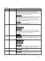
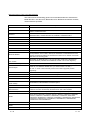
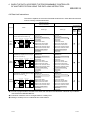
REVISIONS
The manual number is given on the bottom left of the back cover.
Print Date
Dec., 1999
Oct., 2000
Manual Number
Revision
SH(NA)-080010-A First edition
SH(NA)-080010-B Reflect the contents of the function version B.
Put Windows® base software products together from Mitsubishi
Programmable Controller MELSEC series to Mitsubishi integrated FA
software MELSOFT series. Standardize the name from software package
(GPP function) to product name (GX Developer).
Correction
Entire manual (change MELSECNET/10H to MELSECNET/H), Contents,
About Manuals, About the Generic Terms and Abbreviations, Chapter 1
(entire), Section 1.2 (POINT), Section 2.1, 2.5 (2), 2.6.1, 2.6.2, 2.7.1,
2.7.2, Section 3.2.1 (2). 3.3.3 (4), Section 4.1, 4.3, 4.5.2, Section 5.1.1,
5.2, 5.3, 5.4, 5.5, 5.6.1, 5.6.1 (2) 2), 5.6.2, 5.6.4, Section 6.2 to 6.8, 6.9
(POINT before the function), 6.10 to 6.14
Jun., 2001
Addition
Entire manual (add the explanation on MELSECNET/H remote I/O
station), Section 4.3 (4), Chapter 5 POINT
SH(NA)-080010-C Added the description of the model QJ71E71-100 Ethernet interface
module.
Additional model
QJ71E71-100
Correction
About Manuals, The Manual’s Usage and Structure, About the Generic
Terms and Abbreviations, Section 1.1 (1), 1.2, Section 3.3.2 (3) (c),
Section 4.2 (5), 4.3 (3), 4.4 (Table), 4.7, Section 5.4, 5.5 (c), Section 6.2,
6.3, 6.9 (POINT), 6.13 (Function), 6.14 (Function)
Addition
Chapter 2 (entire), Section 5.1, 5.6.4
Oct., 2001
SH(NA)-080010-D
Apr., 2003
SH(NA)-080010-E
Correction
Section 1.2, Section 2.1, 2.3, 2.4, 2.7.2 (4) (POINT), 2.8, Section 4.5.1 (3)
(b), Chapter 5 POINT, Section 5.1.1, 5.4 (4), 5.5 (c) 2), 5.6.4 (2)
(cpuchg), Section 6.5
Additional model
QJ71E71-B5
Deleted model
QJ71E71
Correction
SAFETY PRECAUTIONS, Section 1.2, Section 2.6 (POINT), 2.7, 2.8,
2.9, Section 3.2.1 (2), 3.3, , Section 4.2 (1), 4.6 (1), Section 5.6.4, Section
6.2, 6.3, 6.5, 6.6, 6.7, 6.10 (POINT), 6.11 (POINT), 6.12, 6.13, 6.14
Dec., 2003
SH(NA)-080010-F
Jun., 2004
SH(NA)-080010-G
A-5
Correction
Section 6.13 (POINT), 6.14 (POINT)
Correction
About the Generic Terms and Abbreviations, Section 1.2, Section 2.1.2
(1), Section 3.2.1 (2), Section 4.6, 4.8, Section 5.5 (5)(6), Section 6.4,
6.5, 6.6, 6.7, 6.8, 6.9, 6.11, 6.12
A-5
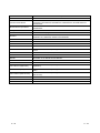
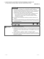
The manual number is given on the bottom left of the back cover.
Print Date
Aug., 2005
Manual Number
SH(NA)-080010-H
Jun., 2006
SH(NA)-080010-I
Revision
Correction
SAFETY PRECAUTIONS, Section 1.2, Section 2.1.2, 2.7, 2.8, 2.9,
Section 6.4, 6.5, 6.6, 6.9, 6.12
Correction
Section 4.2, 4.7, Section 6.4, 6.7, 6.10, 6.11, 6.12, 6.13, 6.14
Addition
Section 6.1
Jun., 2007
SH(NA)-080010-J
Change of a term
"PLC" was changed to "programmable controller".
Correction
About the Generic Terms and Abbreviations, Section 1.2,
Section 3.2.1, 3.3.3, Section 4.2, 4.4, 4.5.2,
Section 6.2 to 6.14
Nov., 2007
SH(NA)-080010-K
Oct., 2008
SH(NA)-080010-L
Correction
Section 6.1
Correction
SAFETY PRECAUTIONS, The Manual's Use and Structure, About the
Generic Terms and Abbreviations, Section 1.1, 1.2, 2.6, Chapter 3,
Section 4.1 to 4.4, 4.5.2, 4.6, Section 5.5.1, 5.2, 5.5, 5.6.2, 5.6.4,
Section 6.1 to 6.7, 6.9 to 6.14
Japanese Manual Version SH-080005-P
This manual confers no industrial property rights or any rights of any other kind, nor does it confer any patent
licenses. Mitsubishi Electric Corporation cannot be held responsible for any problems involving industrial property
rights which may occur as a result of using the contents noted in this manual.
© 1999 MITSUBISHI ELECTRIC CORPORATION
A-6
A-6
INTRODUCTION
Thank you for purchasing the MELSEC-Q series programmable controller.
Before using the equipment, please read this manual carefully to develop full familiarity with the functions
and performance of the Q series programmable controller you have purchased, so as to ensure correct use.
Please forward a copy of this manual to the end user.
CONTENTS (This manual)
SAFETY PRECAUTIONS..............................................................................................................................A- 1
REVISIONS ....................................................................................................................................................A- 5
CONTENTS....................................................................................................................................................A- 7
ABOUT MANUALS ........................................................................................................................................A-11
The Manual's Use and Structure ...................................................................................................................A-12
About the Generic Terms and Abbreviations ................................................................................................A-15
1 OVERVIEW
1- 1 to 1- 5
1.1 Overview.................................................................................................................................................. 1- 1
1.2 Additional Functions in Function Version B or Later.............................................................................. 1- 4
2 USING THE E-MAIL FUNCTION
2- 1 to 2-40
2.1 E-mail Function ....................................................................................................................................... 2- 1
2.1.1 E-mail send and reception by the programmable controller CPU .................................................. 2- 1
2.1.2 Sending e-mail using the programmable controller CPU monitor function .................................... 2- 3
2.2 Configuration and Environment of the Applicable System .................................................................... 2- 5
2.3 Precautions for Using the E-mail Function............................................................................................. 2- 6
2.4 E-mail Specifications............................................................................................................................... 2- 8
2.5 Processing Procedure of the E-mail Function........................................................................................ 2- 9
2.6 E-mail Settings from GX Developer ....................................................................................................... 2-10
2.7 Sending/Receiving E-mail (Attached Files) by the Programmable Controller CPU ............................. 2-15
2.7.1 When sending data as an attached file ........................................................................................... 2-15
2.7.2 When receiving data in the attached file ......................................................................................... 2-20
2.7.3 Contents of the attached files .......................................................................................................... 2-26
2.8 Sending E-mail (Main Text) by the Programmable Controller CPU...................................................... 2-28
2.8.1 When sending data as main text of e-mail ...................................................................................... 2-28
2.9 Sending E-mails Using the Programmable Controller CPU Monitoring Function ................................ 2-32
2.9.1 News setting ..................................................................................................................................... 2-32
2.9.2 Receiving a news e-mail .................................................................................................................. 2-37
3 WHEN COMMUNICATING WITH CC-LINK IE CONTROLLER NETWORK, MELSECNET/H,
MELSECNET/10 RELAY
3- 1 to 3-20
3.1 CC-Link IE controller network, MELSECNET/H, MELSECNET/10 Relay Communication .................. 3- 1
3.2 Range of Accessible Other Station’s Programmable Controllers and Accessible Stations ................. 3- 2
3.2.1 Accessible range and stations ......................................................................................................... 3- 2
3.3 Settings for Accessing Other Stations.................................................................................................... 3- 4
3.3.1 Setting the Station No. <-> IP Information....................................................................................... 3- 5
3.3.2 Convert format between the Network No./station number and IP address/port number .............. 3- 8
3.3.3 Routing parameter settings.............................................................................................................. 3-14
3.4 Procedure for Accessing Other Stations ................................................................................................ 3-20
3.5 Precautions for Accessing Other Stations.............................................................................................. 3-20
A-7
A-7
4 WHEN THE QCPU ACCESSES THE PROGRAMMABLE CONTROLLER OF ANOTHER STATION
USING THE DATA LINK INSTRUCTION
4- 1 to 4- 41
4.1 Other Station Access with the Data Link Instruction.............................................................................. 4- 1
4.2 Precautions for Accessing Other Stations.............................................................................................. 4- 2
4.3 Using the Data Link Instructions............................................................................................................. 4- 5
4.4 Data Link Instructions ............................................................................................................................. 4- 8
4.5 Data Sending/Receiving ......................................................................................................................... 4-11
4.5.1 Data sending/receiving for receive with the main program (SEND/RECV) ................................... 4-12
4.5.2 Data sending/receiving for receive with an interrupt program (SEND/RECVS) ............................ 4-18
4.6 Reading/Writing Word Devices of Other Stations (READ/WRITE)....................................................... 4-22
4.7 Reading/Writing Word Devices of Other Stations (ZNRD/ZNWR)........................................................ 4-30
4.8 Reading/Writing Clock Data, Remote RUN/Remote STOP (REQ)....................................................... 4-36
4.9 Error Codes for Data Link Instructions ................................................................................................... 4-41
5 WHEN USING FILE TRANSFER FUNCTIONS (FTP SERVER)
5- 1 to 5-32
5.1 File Transfer Functions ........................................................................................................................... 5- 1
5.1.1 FTP server support functions of Ethernet module .......................................................................... 5- 2
5.2 File Transferable Range ......................................................................................................................... 5- 4
5.3 FTP Parameter Settings for File Transfer from GX Developer ............................................................. 5- 5
5.4 Procedure and Required Processing on the External Device Side (FTP Client).................................. 5- 7
5.5 Precautions when Using the File Transfer Functions ............................................................................ 5-12
5.6 FTP Commands ...................................................................................................................................... 5-16
5.6.1 File designation method................................................................................................................... 5-16
5.6.2 QCPU user file list ............................................................................................................................ 5-19
5.6.3 Response code ................................................................................................................................ 5-20
5.6.4 FTP operation command ................................................................................................................. 5-21
6 DEDICATED INSTRUCTIONS
6- 1 to 6-70
6.1 Dedicated Instruction List and Available Devices .................................................................................. 6- 1
6.2 ZP.MRECV.............................................................................................................................................. 6- 3
6.3 ZP.MSEND.............................................................................................................................................. 6- 8
6.4 JP/GP.READ ........................................................................................................................................... 6-13
6.5 JP/GP.RECV (for the Main Program)..................................................................................................... 6-19
6.6 Z.RECVS (for Interrupt Programs) ......................................................................................................... 6-24
6.7 J(P)/G(P).REQ (Remote RUN/STOP).................................................................................................... 6-28
6.8 J(P)/G(P).REQ (Clock Data Read/Write) ............................................................................................... 6-34
6.9 JP/GP.SEND ........................................................................................................................................... 6-37
6.10 JP/GP.SREAD ...................................................................................................................................... 6-46
6.11 JP/GP.SWRITE..................................................................................................................................... 6-51
6.12 JP/GP.WRITE ....................................................................................................................................... 6-56
6.13 J(P).ZNRD............................................................................................................................................. 6-63
6.14 J(P).ZNWR............................................................................................................................................ 6-67
INDEX
A-8
Index- 1 to Index- 2
A-8
(Related Manual-1) ··· Q corresponding Ethernet Interface Module User's Manual (Basic)
SH-080009-M
1 OVERVIEW
1.1 Overview of the Ethernet Module
1.2 Features of the Ethernet Module
1.3 Additional Functions in Function Version B or
Later
1.4 Software Configuration
2 SYSTEM CONFIGURATIONS
2.1 Applicable Systems
2.2 Devices Required for Network Configuration
2.3 For Use in Multiple CPU System
2.4 For Use with Basic Model QCPU or Safety
CPU
2.5 For Use with Redundant CPUs
2.6 For Use at MELSECNET/H Remote I/O
Station
2.7 Checking the Function Version and Serial No.
3 SPECIFICATIONS
3.1 Performance Specifications
3.2 Data Codes for Communication
3.3 Relationship Between the External Devices
and Additional Functions for Each
Communication Function
3.4 Ethernet Module Function List
3.5 Dedicated Instruction List
3.6 List of GX Developer Setting Items for
Ethernet Modules
3.7 List of Input/Output Signals to/from the
Programmable Controller CPU
3.8 List of Applications and Assignments of the
Buffer Memory
4 SETTINGS AND PROCEDURES PRIOR TO
OPERATION
4.1 Loading and Installation
4.2 Settings and Procedures Prior to Starting the
Operation
4.3 Components of the Ethernet Module
4.4 Connecting to the Network
4.5 Settings from GX Developer
4.6 Network Parameters Setting the Number of
Ethernet/CC IE/MELSECNET Cards
4.7 Operational Settings
4.8 Self-Diagnostic Tests
4.9 Maintenance and Inspection
A-9
5 COMMUNICATION PROCEDURE
5.1 Overview of the Communication Procedure
5.2 Initial Processing
5.3 Router Relay Parameter
5.4 Confirming the Completion of the Initial
Processing
5.5 Open Settings
5.6 Open Processing/Close Processing of the
Connection
5.7 Pairing Open
5.8 Automatic Open UDP Port
5.9 Corresponding with the QCPU Remote
Password Function
5.10 Hub Connection Status Monitor Function
5.11 Configuring a Network in Redundant System
(Redundant System Support Function)
6 COMMUNICATION USING THE MC PROTOCOL
6.1 Data Communication Function
6.2 Utilizing the MX Component
7 FIXED BUFFER COMMUNICATION
(WITH THE PROCEDURE EXIST CONTROL
METHOD)
7.1 Control Method
7.2 Sending Control Method
7.3 Receiving Control Method
7.4 Data Format
7.5 Programming
8 FIXED BUFFER COMMUNICATION
(WITH THE NO PROCEDURE CONTROL METHOD)
8.1 Control Method
8.2 Sending Control Method
8.3 Receiving Control Method
8.4 Data Format
8.5 Simultaneous Broadcast Using UDP/IP
8.6 Programming
9 COMMUNICATION USING THE RANDOM
ACCESS BUFFER
9.1 Control Method
9.2 Data Format
9.3 Physical and Logical Addresses of the
Random Access Buffer
9.4 Precautions when Creating Programs
A-9
(Related Manual-1) ··· Q corresponding Ethernet Interface Module User's Manual (Basic)
SH-080009-M
10 DEDICATED INSTRUCTIONS
10.1 Dedicated Instruction List and Available
Devices
10.2 ZP.BUFRCV
10.3 Z.BUFRCVS
10.4 ZP.BUFSND
10.5 ZP.CLOSE
10.6 ZP.ERRCLR
10.7 ZP.ERRRD
10.8 ZP.OPEN
10.9 ZP.UINI
11 TROUBLESHOOTING
11.1 How to Check Errors Using LED Displays
11.2 How to Check an Error Through GX
Developer
11.3 Error Code List
11.4 Troubleshooting Flowchart
APPENDIX
Appendix 1 Function Upgrade for the Ethernet
Module
Appendix 2 The QnA/A Series Module
Appendix 3 Installing the Ethernet Module on
Existing Systems
Appendix 4 Processing Time
Appendix 5 ASCII Code List
Appendix 6 References
Appendix 7 External Dimensions
Appendix 8 Program Examples
Appendix 9 Communication Support Tool
(MX Component)
Appendix 10 Differences Between the Ethernet
and the IEEE802.3
Appendix 11 ICMP Protocol Supported by the
Ethernet Module
Appendix 12 Setting Value Recording Sheets
A - 10
A - 10
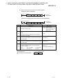
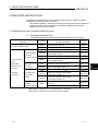
ABOUT MANUALS
The following manuals are also related to this product.
If necessary, order them by quoting the details in the tables below.
Related Manuals
Manual number
(Model code)
Manual name
Q Corresponding Ethernet Interface Module User's Manual (Basic)
This manual explains the specifications of the Ethernet module, data communication procedures with
external devices, line connections (open/close), fixed buffer communication, random access buffer
communication, and troubleshooting.
(Sold separately)
Q Corresponding Ethernet Interface Module User’s Manual (Web function)
This manual explains how to use the Web function of the Ethernet module.
SH-080009
(13JL88)
(Sold separately)
SH-080180
(13JR40)
Q Corresponding MELSEC Communication Protocol Reference Manual
This manual explains the communication methods and control procedures through the MC protocol for
the external devices to read and write data from/to the programmable controller CPU using the serial
communication module/Ethernet module
A - 11
SH-080008
(13JF89)
(Sold separately)
A - 11
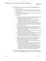
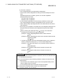
The Manual's Use and Structure
How to use this manual
In this manual, explanations are given for each special function of the Ethernet
modules (QJ71E71-100, QJ71E71-B5 and QJ71E71-B2). Please use this manual
using the following key items below as a reference.
(1) To learn about an overview of the special functions
• Chapter 1 provides an overview of each of the special functions available for
the Ethernet modules.
(2) To use the e-mail transmission/reception function and the
programmable controller CPU monitoring function
• Section 2.2 describes the environment in which e-mails can be used.
• Section 2.6 illustrates the screens for parameter settings using GX Developer
in order to use the e-mail function.
• Section 2.9 describes the parameter settings in order to monitor the status of
the programmable controller CPU.
(3) To communicate with programmable controller CPUs of other
stations via the CC-Link IE controller network, MELSECNET/H,
MELSECNET/10 and Ethernet module
• Section 3.2 describes the accessible range and accessible stations when
accessing other stations via the Ethernet modules.
• Section 3.3 describes the parameter settings using GX Developer in order to
perform data communication with the programmable controller CPUs of other
stations.
• Section 3.3.2 provides an overview of the processing for Station No. <-> IP
information conversion.
(4) To use the file transfer (FTP) function
• Section 5.3 describes the parameter settings using GX Developer in order to
perform the file transfer.
• Section 5.6 describes the FTP operation command on the FTP client (external
device) side that is supported by the Ethernet module.
POINT
To know about the following items, see the Ethernet Interface Module User's
Manual (Basic).
(1) Detailed descriptions of the error codes
Chapter 11 describes troubleshooting, how to check for errors, and detailed
descriptions of error codes for the Ethernet modules.
(2) Storage locations of the error codes for the Ethernet module
Section 11.3 lists the error code storage locations in the buffer memory in the
beginning of the section.
A - 12
A - 12
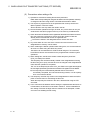
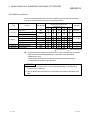
Structure of this manual
(1) Setting Parameters with GX Developer
(a) By setting parameters with GX Developer, the sequence programs for
communicating with external devices can be simplified in the Ethernet
module.
(b) In this manual, parameter settings using GX Developer are explained in
detail for each item displayed on the setting screens.
For details on the types of the setting screens, objectives of the settings,
the setting items and an outline of the setting operation using GX
Developer, see Section 4.5 of the Q Corresponding Ethernet Interface
Module User's Manual (Basic)
(c) Set the required parameters by referring to chapters that explain the
functions to be used, and load the set parameters to the programmable
controller CPU of the Ethernet module installed station.
(2) Setting screen of GX Developer
This manual explains the parameter settings with GX Developer in the following
format:
A - 13
A - 13
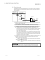
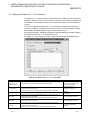
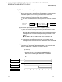
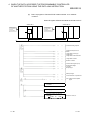
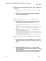
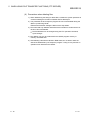
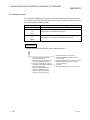
2.6 E-mail Setting from GX Developer
This section explains the setting required by GX Developer to send and receive
e-mails.
For details on how to display each screen, refer to the GX Developer
Operating Manual.
1) Shows how to start
the setting screen.
(1) DNS setting
[Purpose of setting]
Specify the IP address of the DNS server when setting the mail server name using
the domain name by the e-mail setting (see (2)).
[Start procedure]
[Network parameter setting the number of Ethernet/CC IE/MELSECNET cards] → Initial setting
[Setting screen]
2) Shows the setting screen of
GX Developer.
(a) DNS Setting
Designate the internet service provider used by the local station's Fthernet module
and the IP addresses of the domain name servers (DNS) designated by a system
administrator.
1) Select the input format of the IP addresses (decimal/hexadecimal).
2) Designate the IP addresses of the DNS server to DNS servers 1 to 4.
3) Shows a description of
the setting.
Depending on the function used, "(Address:
H)" may be indicated after some
function names. This address indicates the buffer memory address of the Ethernet
module in which the setting values from GX Developer are stored.
For more details on the buffer memory, see Section 3.8 of the Q Corresponding
Ethernet Interface Module User's Manual (Basic).
A - 14
A - 14
About the Generic Terms and Abbreviations
This manual uses the following generic terms and abbreviations to describe the
Model QJ71E71-100, QJ71E71-B5 and QJ71E71-B2 Ethernet interface modules,
unless otherwise specified.
Generic Term/Abbreviation
Description
ACPU
Generic term for AnNCPU, AnACPU, and AnUCPU.
AnACPU
Generic term for A2ACPU, A2ACPU-S1, A2ACPUP21/R21, A2ACPUP21/R21-S1,
A3ACPU, A3ACPUP21/R21.
AnNCPU
Generic term for A1NCPU, A1NCPUP21/R21, A2NCPU, A2NCPU-S1,
A2NCPUP21/R21, A2NCPUP21/R21-S1, A3NCPU, A3NCPUP21/R21.
AnUCPU
Generic term for A2UCPU, A2UCPU-S1, A2ASCPU, A2ASCPU-S1, A3UCPU, A4UCPU.
BUFRCV
Abbreviation for ZP.BUFRCV.
BUFRCVS
Abbreviation for Z.BUFRCVS.
BUFSND
Abbreviation for ZP.BUFSND.
CLOSE
Abbreviation for ZP.CLOSE.
ERRCLR
Abbreviation for ZP.ERRCLR.
ERRRD
Abbreviation for ZP.ERRRD.
Ethernet Address
A machine-specific address that is also referred to as the MAC (Media Access
Control) address. This is used to identify the addresses of external devices over a
network. The Ethernet address of the Ethernet module can be verified on the MAC
ADD column of the rating plate.
Ethernet module
E71 module
Abbreviation for Model QJ71E71-100, QJ71E71-B5 and QJ71E71-B2 Ethernet
Interface Modules. (Indicated as the Ethernet module or E71 in the diagrams)
Ethernet network system
Abbreviation for 10BASE2,10BASE5, 10BASE-T and 100BASE-TX network systems.
GX Developer
Generic product name for SWnD5C-GPPW-E, SWnD5C-GPPW-EA, SWnD5CGPPW-EV, and SWnD5C-GPPW-EVA. ("n" means version 4 or later.)
"-A" and "-V" mean "volume license product" and "version-upgrade product"
respectively.
MELSECNET/10
Abbreviation for the MELSECNET/10 network system.
MELSECNET/H
Abbreviation for the MELSECNET/H network system.
MRECV
Abbreviation for ZP. MRECV.
MSEND
Abbreviation for ZP.MSEND.
Network module
(N/W module)
Abbreviation for interface modules compatible with the CC-Link IE controller network,
MELSECNET/H, MELSECNET/10 network system.
OPEN
Abbreviation for ZP.OPEN.
Opossit device
External device
Generic term for personal computers, computers, work station (WS) and Ethernet
module etc. that are connected by the Ethernet for data communication.
Personal computer
Generic term for IBM PC/AT (or 100% compatible) personal computer.
QCPU
Generic term for Q00JCPU, Q00CPU, Q01CPU, Q02CPU, Q02HCPU, Q06HCPU,
Q12HCPU, Q25HCPU, Q02PHCPU, Q06PHCPU, Q12PHCPU, Q25PHCPU,
Q12PRHCPU, Q25PRHCPU, Q02UCPU, Q03UDCPU, Q04UDHCPU, Q06UDHCPU,
Q13UDHCPU, Q26UDHCPU, Q03UDECPU, Q04UDEHCPU, Q06UDEHCPU,
Q13UDEHCPU and Q26UDEHCPU.
Basic model QCPU
Generic term for Q00JCPU, Q00CPU, and Q01CPU.
High Performance model
QCPU
Generic term for Q02CPU, Q02HCPU, Q06HCPU, Q12HCPU, and Q25HCPU.
Process CPU
Generic term for Q02PHCPU, Q06PHCPU, Q12PHCPU, and Q25PHCPU.
A - 15
A - 15
Generic Term/Abbreviation
Description
Redundant CPU
Generic term for Q12PRHCPU and Q25PRHCPU.
Universal model QCPU
Generic term for Q02UCPU, Q03UDCPU, Q04UDHCPU, Q06UDHCPU, Q13UDHCPU,
Q26UDHCPU, Q03UDECPU, Q04UDEHCPU, Q06UDEHCPU, Q13UDEHCPU and
Q26UDEHCPU.
Built-in Ethernet port QCPU
Generic term for Q03UDECPU,Q04UDEHCPU,Q06UDEHCPU, Q13UDEHCPU, and
Q26UDEHCPU.
Safety CPU
Generic term for QS001CPU.
QCPU station
Abbreviation for the programmable controller mounted QCPU.
QnACPU
Generic term for Q2ACPU, Q2ACPU-S1, Q2ASCPU, Q2ASCPU-S1, Q2ASHCPU,
Q2ASHCPU-S1, QA3ACPU, Q4ACPU and Q4ARCPU.
Q/QnA
Generic term for QCPU and QnACPU.
READ
Abbreviation for JP.READ and GP.READ.
RECV
Abreviation for JP.RECV and GP.RECV.
RECVS
Abbreviation for Z.RECVS.
Reference Manual
Abbreviation for the Q Corresponding MELSEC Communication Protocol Reference
Manual.
REQ
Abbreviation for J.REQ, JP.REQ, G.REQ and GP.REQ.
SEND
Abbreviation for JP.SEND and GP.SEND.
SREAD
Abbreviation for JP.SREAD and GP.SREAD.
SWRITE
Abbreviation for JP.SWRITE and GP.SWRITE.
UINI
Abbreviation for ZP.UINI.
User's Manual (Application)
Abbreviation for the Q Corresponding Ethernet Interface Module User's Manual
(Application).
User's Manual (Basic)
Abbreviation for the Q Corresponding Ethernet Interface Module User's Manual
(Basic).
User’s Manual (Web function)
Abbreviation for the Q Corresponding Ethernet Interface Module User’s Manual
(Web function)
WRITE
Abbreviation for JP.WRITE and GP.WRITE.
ZNRD
Abbreviation for J.ZNRD and JP.ZNRD.
ZNWR
Abbreviation for J.ZNWR and JP.ZNWR.
A - 16
A - 16
1 OVERVIEW
MELSEC-Q
1 OVERVIEW
This manual provides information on the special functions of the MELSEC-Q Series
Ethernet Interface Modules (hereinafter called the Ethernet module).
When applying the following program examples to the actual system, make sure to
examine the applicability and confirm that it will not cause system control problems.
This chapter describes an overview of the special functions that are available for the
Ethernet module.
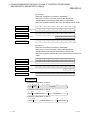
1.1 Overview
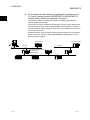
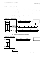
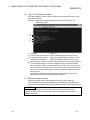
(1) Send/receive e-mails (Details are explained in Chapter 2)
This function allows the transmission and reception of a maximum of 6k words of
CPU information as the main text or attached file of e-mail to/from computers and
programmable controller CPUs via the Internet.
Furthermore, by setting the automatic notification, the Ethernet module sends
e-mail when the notification conditions set by the user match for the
transmission from programmable controllers.
Internet network
(Public line)
Internet service provider
Internet
service provider
Mail server
1-1
1-1
1
1 OVERVIEW
MELSEC-Q
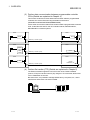
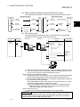
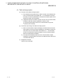
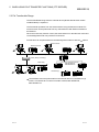
(2) Communicate with other stations' programmable controllers via the
CC-Link IE controller network, MELSECNET/H, MELSECNET/10
network system (Details are explained in Chapter 3)
1
This function enables accessing other stations via multiple networks in the
network system shown below.
This function is used for multiple relays through a network in which the Ethernet
and CC-Link IE controller network, MELSECNET/H, MELSECNET/10 network
systems coexist as well as through a network in which multiple Ethernet network
systems are connected.
Using this function, another station's programmable controller can be accessed
via the CC-Link IE controller network, MELSECNET/H, MELSECNET/10 and
Ethernet network systems.
Access destination
Access source
Ethernet
Ethernet
CC-Link IE controller network,
MELSECNET/H,
MELSECNET/10
1-2
1-2
1 OVERVIEW
MELSEC-Q
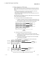
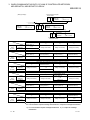
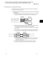
(3) Perform data communication between programmable controller
CPUs (Details are explained in Chapter 4)
This function sends and receives data to/from another station's programmable
controller CPU via the Ethernet using the data link instructions
(SEND/RECV/READ/WRITE/REQ/ZNRD/ZNWR).
It also sends and receives data to/from another station's programmable controller
CPU via the Ethernet and CC-Link IE controller network, MELSECNET/H,
MELSECNET/10 network systems.
E71
QCPU
E71
QCPU
SEND
Buffer
memory
RECV
Ethernet (+ network system)
E71
QCPU
E71
QCPU
READ
WRITE
ZNRD
Device
Ethernet (+ network system)
ZNWR
E71
QCPU
E71
QCPU
REQ
Remote
RUN/STOP, etc.
Ethernet (+ network system)
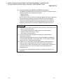
(4) Perform file transfer (FTP) (Details are explained in Chapter 5)
The Ethernet module supports the server function of the TCP/IP standard
protocol, FTP (File Transfer Protocol). By using the FTP commands, QCPU files
can be read/written in file units.
Because of this, it is possible to manage QCPU files by computers, etc., and to
transfer files and browse a file list as needed.
PC
Ethernet
(FTP client)
1-3
(FTP server)
1-3
1 OVERVIEW
MELSEC-Q
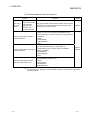
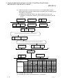
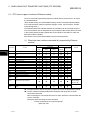
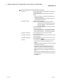
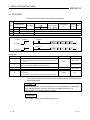
1.2 Additional Functions in Function Version B or Later
The following table lists the functions additionally provided for the Ethernet modules of
function version B or later.
POINT
(1) The added/changed functions shown in this section includes the functions
added in the first products or later of function version B and function version D.
For the function version, serial No., and software version of the Ethernet module
and related products (CPU module, and GX Developer) that can use the
added/changed functions, refer to Section 2.7.
(2) Refer to Appendix 1.1 concerning a comparison of functions in the different
Ethernet module function versions.
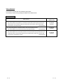
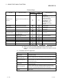
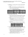
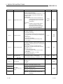
(1) Functions added for function version B
Function
Overview
Reference
section
Sending files in CSV
format as attachment
Sending main text
Sends a file in CSV format as attachment to e-mail from the
Ethernet module.
Sends main text of up to 960 words from the Ethernet module.
When using
The following encoding/decoding is supported.
Chapter 2
the e-mail
• Encode the Subject using 7 bits encoding and send it from
function
Support for encoding/
the Ethernet module.
decoding
• Decode and receive an e-mail encoded with Quoted
Printable by the Ethernet module.
Unlocks/locks the remote password of the QCPU. The unlock
Remote password
processing enables access to the QCPU using FTP
When using
check
commands.
the file transfer
Chapter 5
(FTP server)
The QCPU transfers files to the control CPU/non-control CPU
Support for multiple
function
of the Ethernet module when a multiple CPU system
CPU systems
configuration is used.
1-4
1-4
1 OVERVIEW
MELSEC-Q
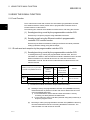
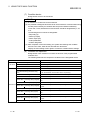
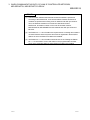
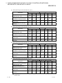
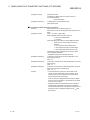
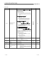
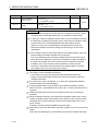
(2) Function added for function version D
Function
Sending character
strings in the e-mail’s
main text by the
programmable
controller CPU
monitoring function
Overview
Reference
section
The programmable controller CPU monitoring function allows
transmission of character string information stored in word
devices by the e-mail’s main text.
Chapter 2
In the following data link instructions, the target station
number 65 to 120 can be specified. (Specification of the
station number 65 to 120 in the CC-Link IE controller network
is available.)
Specifying target station number in
• SEND
data link instructions
• READ/SREAD
• WRITE/SWRITE
• REQ
In the following data link instructions, the target station’s CPU
type can be specified ((S1)+3). (Specification of
control/standby system or system A/B in the redundant
Specifying target station’s CPU type in
system is available.)
data link instructions
• READ/SREAD
• WRITE/SWRITE
• REQ
The data length can be specified up to 960 words in the
1
following data link instructions:
• SEND
Increased data length of data link
• RECV/RECVS
instructions (480 to 960 words)
• READ/SREAD
• WRITE/SWRITE
Chapter 4
Chapter 6
When using
the e-mail
function
1 In a multiple network system, when transferring data exceeding 480 words to a station of
another network No., specify the Q series models to all of the request source, relay station
and request target.
1-5
1-5
2 USING THE E-MAIL FUNCTION
MELSEC-Q
2 USING THE E-MAIL FUNCTION
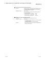
2.1 E-mail Function
The e-mail function sends and receives CPU information (programmable controller
CPU status and device values) to/from PCs or programmable controller CPUs in
remote locations via the Internet.
The following two methods are available to send/receive e-mail using this function.
2
(1) Sending/receiving e-mail by the programmable controller CPU
Executed by a sequence program using dedicated instructions.
(2) Sending e-mail using the Ethernet module’s programmable
controller CPU monitor function
Executed by the Ethernet module according to the Ethernet module parameter
setting (notification setting) using GX Developer.
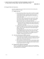
2.1.1 E-mail send and reception by the programmable controller CPU
(1) Sending/receiving e-mail by the programmable controller CPU
In sending/receiving e-mail by the programmable controller CPU, the CPU
information of a station in which an Ethernet module is installed is sent to another
Ethernet modules or an external device such as a PC as the main text or
attached file of e-mail. E-mail sent from other Ethernet modules and PCs can
also be received.
External device
Sending e-mail by the programmable
controller CPU (MSEND instruction)
Ethernet module
(MRECV
instruction)
Subject
(
Attached
file
PC
Portable terminal
(device that
cannot handle
attached files)
Remarks
1)
—
Binary format
Binary to ASCII conversion
Maximum 6k words
Binary to CSV conversion
Main text Designating using ASCII data
Maximum 960 words.
1 The Ethernet module receives the Subject without decoding.
2-1
(a)
Sending e-mail by the programmable controller CPU (MSEND instruction)
Data transmission is performed via the main text or attached file of e-mail
using the MSEND instruction.
1) For an attached file, device data and other information is sent by
converting into binary/ASCII/CSV data format.
2) For the main text, ASCII code data (character string data) created by a
sequence program is sent.
(b)
Receiving e-mail by the programmable controller CPU (MRECV instruction)
Receives attached file data of e-mail using the MRECV instruction. The
main text data of e-mail cannot be received.
2-1
2 USING THE E-MAIL FUNCTION
MELSEC-Q
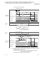
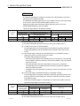
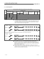
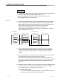
(2) Data conversion method used by the Ethernet module
The following shows the data conversion method used by the Ethernet module.
Programmable
controller CPU
MSEND
instruction
When sending e-mails
Mail
server
Mail
server
When receiving e-mails
Subject
(ASCII data)
Encode
(Base64/7bit)
Main text
(ASCII data)
Encode
(7bit)
Main text
(ASCII data)
Encode
(Base64)
Attached file
(binary data)
Programmable
controller CPU
(Does not decode)
Subject
(ASCII data)
Cannot be
received
MRECV
instruction
(Binary data)
Attached file
(binary data)
(ASCII data)
Decode
(Base64/7bit/8bit
/Quoted Printable)
(CSV data)
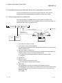
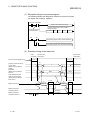
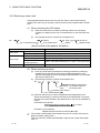
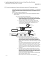
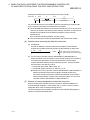
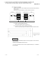
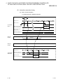
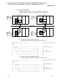
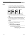
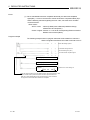
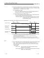
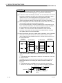
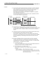
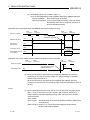
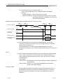
(3) Flow of the e-mail
The following diagram illustrates the flow of e-mail sent by the programmable
controller CPU to its reception by the external device:
Programmable
controller CPU
Ethernet
module
Mail server
Mail server
3)
MSEND
(Mail send)
Ethernet
module
Programmable
controller CPU
Checks whether or not any mails
were received
1)
No mail
received
Stores information
receive mail
2)
Mail send
Mails received
4)
Confirms
information of
receive mail
Request to receive mail
MRECV
(Reads receive
mail)
Stores receive mail
5)
PC
1) Send an e-mail to the send mail server of the local station's Ethernet module.
2) The send mail server of the local station's Ethernet module sends the e-mail
to the receive mail server of the send destination device.
[When receiving by the Ethernet module]
3) The Ethernet module checks whether or not any mails have arrived at the inquiry
interval set with GX Developer, and stores the results to the buffer memory.
4) By executing the MRECV instruction, the Ethernet module reads e-mails from
the e-mail server to the mail buffer.
The programmable controller CPU reads one e-mail and stores it in the mail
buffer of the programmable controller CPU's device.
By user designation with the MRECV instruction, the Ethernet module
reads the number of remaining receive mails on the mail server and
stores this number in the buffer memory.
[When receiving by a PC]
5) Mails can be received using applications such as Internet Mail.
POINT
The e-mail send/reception function by the programmable controller CPU and the
communication function using the random access buffer cannot be used together.
Only one of them can be used at any given time.
2-2
2-2
2
2 USING THE E-MAIL FUNCTION
MELSEC-Q
2.1.2 Sending e-mail using the programmable controller CPU monitor function
(1) Monitor function of the programmable controller CPU
The monitor function of the programmable controller CPU is used to regularly
monitor the status of the programmable controller CPU and device values, and
send e-mail to the designated external device when they match with the
notification conditions (programmable controller CPU status and device values)
set by the user.
Sending e-mail using the programmable
controller CPU monitor function
1
(notification setting) ( )
(
Subject
Attached
file
Main text
External device
Ethernet module
Portable terminal
(MRECV
PC
(device that cannot
instruction)
handle attached files)
Remarks
2
)
—
Binary format
Maximum 960
words
Binary to ASCII conversion
Binary to CSV conversion
Binary format
Maximum 960
words.
Binary to ASCII conversion
1 For the notification of CPU status monitoring, only the Subject (that stores the
programmable controller CPU status) will be sent.
2 The Ethernet module receives the Subject without decoding.
(a)
(b)
(c)
(d)
The programmable controller CPU in the Ethernet module loaded station is
monitored for every CPU inquiry time interval set by the user. The following
information can be registered as the notification conditions.
1) Device monitoring of the programmable controller CPU
• Monitoring the numeric values stored in the word device
• Monitoring the bit device ON/OFF status
2) Monitoring of the programmable controller CPU status
• Monitoring the CPU module status (RUN/STOP/PAUSE)
The device monitoring result of the programmable controller CPU is sent by
either the main text or attached file of e-mail.
1) The attached file is sent by converting the device monitoring data into
binary/ASCII/CSV data format.
2) The main text is sent by converting the device monitoring data into
Binary or ASCII format data.
As for the status monitoring result of the programmable controller CPU, only
the Subject (that stores the programmable controller CPU status) is sent.
When more than one send mail address are specified in the notification
setting, the smallest numbered address is set in the "To" field of the mail
header.
The other addresses are set into the "Cc" field for transmission.
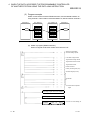
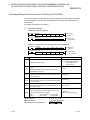
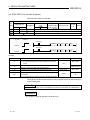
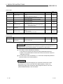
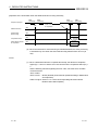
(2) Data conversion method used by the Ethernet module
The following shows the data conversion method used by the Ethernet module.
CPU monitoring
Ethernet
module
Subject
(binary data)
(ASCII data)
Encode
(Base64/7bit)
Mail
server
(binary data)
Main text
(binary data)
(ASCII data)
Encode
(7bit)
(binary data)
Attached file
(binary data)
(ASCII data)
Encode
(Base64)
(CSV data)
2-3
2-3
2 USING THE E-MAIL FUNCTION
MELSEC-Q
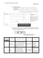
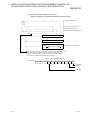
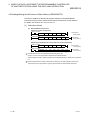
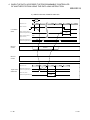
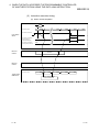
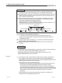
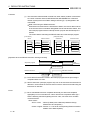
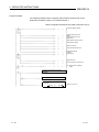
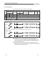
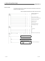
(3) Flow of the e-mail
The diagram shown below illustrates the flow of e-mails from the local station's
Ethernet module to the external device after the monitor values match with the
news conditions.
Programmable
controller CPU
Status
Device value
Ethernet module
1) Read monitoring
information
2) Check news
conditions
No match
Mail server
Match
3) Send mail
4)
External
device
1) Reads the monitoring information (such as status and device values) of the
programmable controller CPU.
2) Checks whether the monitoring information read and the news conditions set
by the user match. (Checks match/mismatch of the news conditions.)
3) Sends an e-mail when the monitored values match with the news conditions.
Multiple news conditions may be set so that an e-mail can be sent
(notified) when any of the conditions matches. (See Section 2.9.1.)
Set the CPU inquiry time interval used by the Ethernet module to monitor
the programmable controller CPU, considering the interval of change
time in the monitoring target.
After a news condition match occurs, the Ethernet module must confirm
the mismatches of other news conditions for the same monitoring target.
The next e-mail can be sent only after the Ethernet module confirms the
mismatches of these news conditions.
4) The Subject of e-mail, which is sent when the notification conditions match, is
fixed data. The format of the Subject is as follows (see Section 2.9.2):
• When monitoring the CPU status
Subject = "No. of transmissions, CPU model name, Status, Detection
time"
• When monitoring the CPU device
Subject = "No. of transmissions, Matched condition device, Monitoring
value, ... "
POINT
The e-mail transmission function of the programmable controller CPU and the
communication function using the random access buffer can be used together.
2-4
2-4
2 USING THE E-MAIL FUNCTION
MELSEC-Q
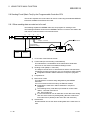
2.2 Configuration and Environment of the Applicable System
This section explains the environment and system configuration for using the e-mail
function from the Ethernet module.
Internet
(Public line)
Internet service provider
Internet service provider
Public line
Router
Router
Ethernet
Proxy server
DNS server
TA/modem
SMTP/POP3
(Mail server)
Ethernet
Proxy server
Ethernet
DNS server
SMTP/POP3
(Mail server)
Ethernet
Ethernet module
External device
Ethernet module
External device
(1) E-mails can be sent and received in an environment where the Internet service is
available as shown above.
(2) Set each Internet mail setting value for the Ethernet module and PC following the
directions from the Internet service provider or system administrator.
(3) Each of the Ethernet module parameters for using the e-mail function is set with
GX Developer.
2-5
2-5
2 USING THE E-MAIL FUNCTION
MELSEC-Q
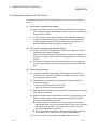
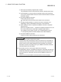
2.3 Precautions for Using the E-mail Function
The following explains precautions when using the e-mail function of the Ethernet
module.
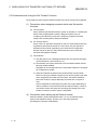
(1) Precautions regarding the system
(a) Design the system so that the entire system operates normally at all times
when sending/receiving e-mails to/from a running system and controlling the
programmable controller.
(b) In order to avoid programmable controller system malfunctions caused by
receptions of illegal e-mails from the outside sources, take precautions in
preventing illegal e-mails from being received on the mail served on the
Ethernet module side (using an anti-virus program, etc).
(2) Precautions regarding the external device
(a) E-mails can be sent to programmable controller CPU stations in which Q
series Ethernet modules are installed.
Since the conventional A/QnA series Ethernet modules do not have the email function, e-mails cannot be sent to those programmable controller CPU
stations.
(b) To send files to the Ethernet module as attachments to e-mail, specify the
encoding method (Base 64/7 bits/8 bits/Quoted Printable) of the attached
files.
(3) Common precautions
(a) The Ethernet module stores the data of attached files received from the
external device in the device specified by the MRECV instruction without
converting it from ASCII to binary.
(b) The maximum sizes of data that can be sent/received by the Ethernet
module are as follows:
• Data size of attached files: Up to 6k words
• Data size of main text: Up to 960 words
(c) Mails that are sent and received do not support encrypted data, compressed
data, and data conversion.
(d) When the external device could not be found in an e-mail sending from the
Ethernet module, the error code can be checked through the reception
processing with the MRECV instruction.
If an external device cannot be found when sending e-mail using the
MSEND instruction, failure of e-mail transmission may not be recognized,
depending on the operation of the mail server. Be sure to verify the
receiver's e-mail address in advance.
Error codes are stored within the control data of the MRECV instruction.
(For details on error codes, refer to the User’s Manual (Basic).)
(e) The e-mail function is supported for the SMTP and POP3 servers.
2-6
2-6
2 USING THE E-MAIL FUNCTION
(f)
MELSEC-Q
When communication errors of e-mails cannot be checked by a dedicated
instruction, check the error codes stored in the mail send/reception error log
area of the buffer memory.
(g) If e-mails cannot be received, try one of the following.
1) Execute the MRECV instruction once.
2) Shorten the "Inquiry interval" time in the e-mail settings of GX
Developer.
3) Check the number of incoming mails remaining on the mail server.
(Can be checked with the buffer memory address 5870H area.)
(h) When the receive data of an e-mail sent using the MSEND instruction is
abnormal (garbled characters, etc.), review the transmission data format
(binary/ASCII/CSV) designated with the MSEND instruction.
The Subject should be designated in ASCII code data. (It is not converted
to ASCII format.)
(i)
Confirm with a system administrator regarding the minimum time intervals for
accessing the mail server when sending mails, reading receive mails, and
inquiring whether or not there are receive mails.
Depending on the mail server's security setting, frequent access may be
prohibited.
(j)
The e-mail send/reception function using the programmable controller CPU
and the communication function using the random access buffer cannot be
used together. Only one of them can be used at a time.
The e-mail send function using programmable controller CPU monitoring
and the communication function using the random access buffer can be
used together.
(k) A Subject that has been sent by the MSEND instruction from an Ethernet
module of the following versions, cannot be received normally by the
MRECV instruction.
• Ethernet modules with serial numbers where the first 5 digits are 03101
or less
Different methods are used for converting Subject data at send and
reception. (See Section 2.1.1 (2).)
• When sending: Encodes the Subject and then send it.
• When receiving: Receives the Subject without decoding it.
2-7
2-7
2 USING THE E-MAIL FUNCTION
MELSEC-Q
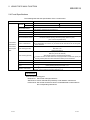
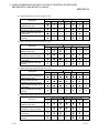
2.4 E-mail Specifications
The following table lists the specifications of the e-mail function.
Item
Data size
Specification
Attached file
6 k words
1
Main text
960 words
1
Data transfer method
When sending: Sends either a file as attachment or main text (select one).
When receiving: Received a file as attachment.
Subject
Us-ASCII format or ISO-2022-JP (Base 64)
Attached file format
MIME format
MIME
Version 1.0
Binary/ASCII/CSV can be selected.
File name: XXXX.bin (binary), XXXX.asc (ASCII), XXXX.csv (CSV)
(CSV: Comma Separated Value)
Data of attached file format
Transmission
Division of attached file
Cannot be divided (only one file can be sent/received)
If any divided files are received, only the first file will be received and the remaining files
will be discarded.
When sending (encode)
Subject: Base 64/7 bits
Main text: 7 bits
Attached file: Base 64
specifications
Transmission
and reception
data
When receiving (decode)
Subject: (Does not decode)
Main text: (Cannot be received)
Attached file: Base 64/7 bits/8 bits/Quoted Printable
If e-mail is sent from the external device to the programmable controller side, specify the
encoding method (Base 64/7 bits/8 bits/Quoted Printable) of the attached file.
Encryption
No
Compression
No
Communication with mail
server
Operation check mailer
SMTP (sending server) Port number = 25
POP3 (receiving server) Port number = 110
Microsoft® Corporation Internet Explorer 5.0 (Outlook Express 5.5/Outlook Express 5)
Netscape® Communications Corporation Netscape® 4.05
REMARKS
Internet mail terminology list:
DNS server: Server that manages networks
SMTP server: Server that delivers (transfers) e-mail between mail servers
POP3 server: Server that transfers received e-mail addressed to subscribers to
the corresponding subscribers
2-8
2-8
2 USING THE E-MAIL FUNCTION
MELSEC-Q
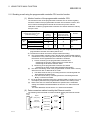
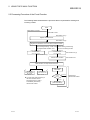
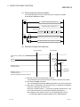
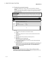
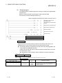
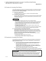
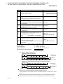
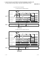
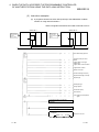
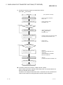
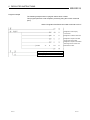
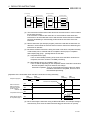
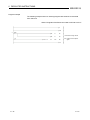
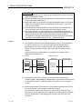
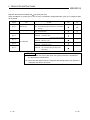
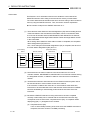
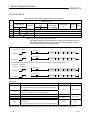
2.5 Processing Procedure of the E-mail Function
The following flowchart illustrates the procedure that is required before sending and
receiving e-mails:
Start
When DNS is not used
When DNS is used
See Section 2.6 (1)
Register the DNS server
See Section 2.6 (2)
Register the mail address of the local station's Ethernet module
When sending/receiving e-mails using When sending e-mails using
the programmable controller CPU
the CPU monitoring function
Register the mail address of
the external device
(with news setting)
Register the mail address of
the external device
(without news setting)
See Section 2.6 (3)
See Section 2.6 (3)
Set the news condition
See Section 2.9.1
Reset the CPU, or Stop and Run the CPU
1
1
Send/receive
data as an attached
file of e-mail
Send data as
main text of e-mail
See Section 2.7
See Section 2.8
1 The open and close processing of
the communication line for
sending/receiving e-mails is
automatically executed by
the Ethernet module.
2-9
Read the CPU
information
News
condition
matching
Unmatched
Matched
Performed by
the Ethernet module
1
Send E-mail
(news information)
2-9
2 USING THE E-MAIL FUNCTION
MELSEC-Q
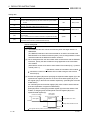
2.6 E-mail Setting from GX Developer
This section explains the settings required by GX Developer to send and receive
e-mails.
For details on how to display each screen, refer to the GX Developer Operating
Manual.
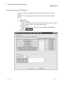
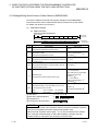
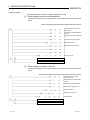
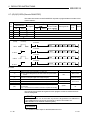
(1) DNS setting
[Purpose of setting]
Specify the IP address of the DNS server when setting the mail server name
using the domain name by the e-mail setting (see (2)).
[Start procedure]
[Network parameter setting the number of Ethernet/CC IE/MELSECNET
cards] → Initial setting
[Setting screen]
2 - 10
2 - 10
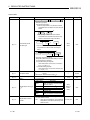
2 USING THE E-MAIL FUNCTION
MELSEC-Q
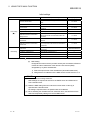
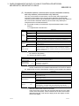
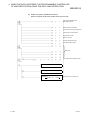
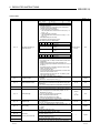
Initial settings
Item name
Timer setting
( 1)
DNS setting
Description of setting
Setting range/options
TCP ULP timer
Set the time of packet existence at TCP data send.
2 to 32767
TCP zero window timer
Set the interval for checking the receive enabled
status.
2 to 32767
TCP resend timer
Set the time to resend at TCP data send.
2 to 32767
TCP end timer
Set the confirmation wait time at TCP close
processing.
2 to 32767
IP assembly timer
Set the wait time for division data packets.
1 to 32767
Response monitoring timer
Set the response wait time.
2 to 32767
Destination existence confirmation
starting interval
Set the time to start confirming existence of an
external device after communication with it has
terminated.
1 to 32767
Destination existence confirmation
interval timer
Set the time interval between reconfirming
existence.
1 to 32767
Destination existence confirmation
resend timer
Set the number of times to reconfirm existence
when a response to the existence confirmation is
not received.
1 to 32767
Input format
Select the input format of the IP addresses of the
DNS servers.
decimal/hexadecimal
IP address of DNS server 1
Set IP address of DNS server 1.
—
IP address of DNS server 2
Set IP address of DNS server 2.
—
IP address of DNS server 3
Set IP address of DNS server 3.
—
IP address of DNS server 4
Set IP address of DNS server 4.
—
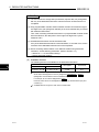
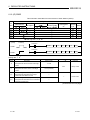
1 See Section 5.2 of the User's Manual (Basic)
(a)
DNS setting
Designate the Internet service provider used by the local station's Ethernet
module and the IP addresses of the domain name servers (DNS)
designated by a system administrator.
1) Select the input format of the IP addresses (decimal/hexadecimal).
2) Designate the IP addresses of the DNS servers to DNS servers 1 to 4.
POINT
(1) The DNS servers manage networks.
DNS settings are required to search for the SMTP server and POP3 server
from a domain name.
(2) Make the DNS setting when the mail server name shown in item (2) is
specified with a domain name.
No setting is required when it is specified with an IP address.
(3) When obtaining the IP addresses from a domain name, the DNS servers are
searched sequentially starting from the first DNS server.
2 - 11
2 - 11
2 USING THE E-MAIL FUNCTION
MELSEC-Q
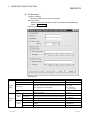
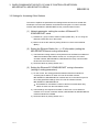
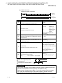
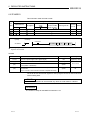
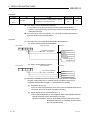
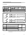
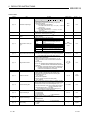
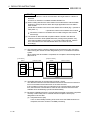
(2) E-mail setting
[Purpose of setting]
Perform the setting to use the e-mail function.
[Start procedure]
[Network parameter setting the number of Ethernet/CC IE/MELSECNET
cards] →E-mail setting
[Setting screen]
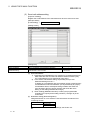
[Setting item]
Item name
Password
Mail address
Description of setting item
Setting range/option
Set the password to the mail server
Set the mail address for the Ethernet module
—
—
• Check mark
General
(Inquire)
Select whether or not to make inquiries to the incoming mail
Check of mail
setting
• No check mark
server regarding the receiving status
(Do not inquire)
Set the time interval and unit for making inquiries to the
• 30 s to 24 h
At every
incoming mail server
• h/min/s
SMTP server name Set the send mail server name
—
Mail send
• Decimal
Input format
Select the input format of the send mail server's IP address
setting
• Hexadecimal
IP
address
Set
the
IP
address
of
send
mail
server
00000001H to FFFFFFFEH
Mail server
name
POP server name Set the receive mail server name
—
Select the input format of the receive mail server's IP
• Decimal
Mail receive
Input format
address
• Hexadecimal
setting
IP address
2 - 12
Set the IP address of the receive mail server
00000001H to FFFFFFFEH
2 - 12
2 USING THE E-MAIL FUNCTION
MELSEC-Q
(a) General settings
Designate the mail setting values that have been registered with the Internet
service provider of the local station's Ethernet module or the mail registration
information designated by the system administrator.
1) Password:
Designate the mail password of the local station's Ethernet module.
2) Mail address:
Designate the mail address of the local station's Ethernet module.
3) Check receive mails:
Select whether or not to check if receive mails have arrived and set the
checking time interval when incoming mails are checked.
When receive mail check is designated, set the time interval for inquiring the
mail server whether or not there are mails addressed to the user.
The following table shows each setting range of the inquiry time intervals for
checking receive mails. (30 s to 24 h)
Time units
Setting range (default: 5 min)
h
1 to 24
min
1 to 1440
s
30 to 3600
POINT
If the inquiry time interval from the programmable controller CPU or other module to
the server is short because of the POP3 server specifications, access may be
restricted (lock status) on the server side.
Check the POP3 server specifications, and set the inquiry time interval accordingly.
(It is recommended to set the setting value of the inquiry time interval to the default
(5 minutes) or more.)
(b) Mail server name
Set the Internet service provider and the domain name or IP addresses of the mail
servers designated by the system administrator, used by the local station's
Ethernet module.
1) Designate the domain name of the mail server.
2) Select the input format (decimal/hexadecimal) of the IP addresses.
3) Set the IP address of the outgoing mail server (SMTP).
4) Set the IP address of the incoming mail server (POP3).
POINT
• The SMTP server delivers (transfers) e-mails between mail servers.
• The POP3 server transfers received e-mails addressed to users to the
corresponding users.
• The mail server names must be designated to use the e-mail function.
(See POINT of (1).)
2 - 13
2 - 13
2 USING THE E-MAIL FUNCTION
MELSEC-Q
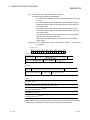
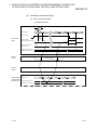
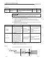
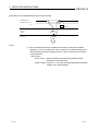
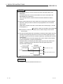
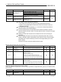
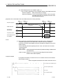
(3) Send mail address setting
[Purpose of setting]
Register the e-mail address of the external devices where e-mail is to be sent.
[Start procedure]
[E-mail setting] → Send e-mail address setting
[Setting screen]
[Setting item]
Item name
Send mail address
Description of setting
Set the mail address of the transmission destination
Notification setting
Select whether or not to set news
Setting range/Selections
—
• Execute news
• No execute
(a) Send mail address
1) Designate the mail addresses of a maximum of 16 external devices to
which mails are sent from the local station's Ethernet module. (Only
one e-mail address can be specified for each area.)
2) In the send e-mail address setting, sequentially set up e-mail
addresses starting from No. 1.
To delete an e-mail address with a mid-setting number, specify dummy
e-mail addresses before that address. (If it is preceded by any empty
e-mail address areas, subsequent setting numbers and areas will
move forward to fill in any empty numbers and areas after each
setting, so the setting numbers will change.)
3) When sending (MSEND instruction) e-mail by the programmable
controller CPU, specify these setting numbers (1 through 16) in the
control data.
(b) Notification setting (News designation)
Designate whether or not to send the news information set with the CPU
monitoring function.
Item
Notification setting
Explanation
Execute news
No execute
For more details on the notification settings, see Section 2.9.
2 - 14
2 - 14
2 USING THE E-MAIL FUNCTION
MELSEC-Q
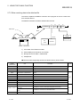
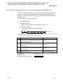
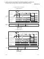
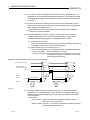
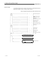
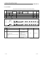
2.7 Sending/Receiving E-mail (Attached Files) by the Programmable Controller CPU
This section explains how to send and receive attached files of e-mail using the
dedicated instructions (MSEND/MRECV) available for the Ethernet module.
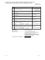
2.7.1 When sending data as an attached file
The following explains the MSEND instruction and program for sending e-mail.
The following illustration shows how the MSEND instruction is used to store data in an
attached file and send it to an external device.
ZP.MSEND
1)
2)
3)
4)
"Un"
(S1)
(S2)
(D)
Mail server
Subject + attached file
Mail address
(Parameter setting)
I/O No.
QCPU
Destination
5) Main text of mail
QJ71E71
6) Attached file
(.bin/.asc/.csv)
1) I/O number of the Ethernet module
2) Control data (such as send mail address)
This indicates the mail address of the send destination device set on the send mail
address settings screen.
3) Send mail (subject + attached file)
Subject consists of No. of transmissions and the character data designated by the
sequence program. (It is not converted to ASCII format.)
The Subject should be designated in the sequence program in ASCII
characters.
4) Complete bit
5) Main text of mail
There is no data for the main text of mail.
The send data is included in the attached file.
6) Attached file
This indicates the device data designated by the MSEND instruction.
The attached file is sent in either one of binary format, ASCII format or CSV format.
The transmission format for attached file is designated in the control data of the
MSEND instruction.
(See (3) 1.)
2 - 15
2 - 15
2 USING THE E-MAIL FUNCTION
MELSEC-Q
(1) Send using the sequence program
The following explains how an e-mail is sent by the sequence program.
See Chapter 6 MSEND for detail.
Direction
Create control data at D20 and on
Create send data at D200 and on
Send the e-mail
ZP.MSEND
M10
"U0"
D20
D200
M10
M11
Processing program when normal completion
M11
Processing program when abnormal completion
(2) Execution timing of the instruction
Initial processing
E-mail sending
1)
Initial normal completion signal
(X19)
2)
MSEND
MSEND
instruction
3)
1 scan
MSEND instruction
completion device
MSEND instruction
completion device + 1
(Normal completion/abnormal completion)
Abnormal
completion
1) Start the local station programmable controller.
The parameters for the e-mail function are stored in the Ethernet module.
2) Execute the MSEND instruction.
The e-mail designated with the MSEND instruction is sent to the mail server.
3) When the e-mail sending to the send mail server is completed, the MSEND
instruction completion device turns on.
When the completion device + 1 (abnormal completion signal) turns on, the
error code is stored in the control data completion status ((S1)+1).
For details on the causes of errors, see "Troubleshooting" in the Q
Corresponding Ethernet Interface Module User's Manual (Basic).
2 - 16
2 - 16
2 USING THE E-MAIL FUNCTION
MELSEC-Q
(3) Sample program
The following shows a sample program for sending e-mails by the programmable
controller CPU.
Perform e-mail send processing using the send command (X20).
The contents of the send data are shown in (4).
When I/O signals of the Ethernet module are X/Y00 to X/Y1F.
Designate ASCII as the send
data format.
Designate the send destination
number.
Designate the send data length.
Designate the subject length.
Designate subject.
Designate the attached file.
Send the e-mail.
Processing program when normal completion
Processing program when abnormal completion
REMARKS
When an error occurs while sending e-mail from the sending mail server to an
external device, an error code is stored in the receiving error log area.
2 - 17
2 - 17
2 USING THE E-MAIL FUNCTION
MELSEC-Q
1 The following shows the transmission format of the attached file designated in the
control data of the MSEND instruction.
For more details on the binary format/ASCII format/CSV format designation, see
the MSEND Instruction in Chapter 6, "Dedicated Instructions."
b12
to
b8
Complete type
Designate the transmission format of the attached file.
Setting values for designating the
attached file transmission format
b12
b11
b10
b9
b8
0
0
0
0
0
Format set
Binary
Applicable station
Ethernet module
Description of processing
Sends the attached file in binary format.
(
.bin)
Sends the attached file in ASCII format.
0
1
0
0
0
ASCII
PC/UNIX
The Ethernet module converts the attached file
from binary to ASCII. (
.asc)
Sends the attached file in CSV format.
0
1
0
0
1
CSV
PC/UNIX
The Ethernet module converts the attached file
from binary to CSV. (
.csv)
(a) Designate binary format when communicating between Ethernet modules.
The attached file of the MSEND instruction will be sent as is.
The name of the attached file is mmddhhss.bin (system date.bin).
mm: Month dd: Date hh: Hour ss: minute
(b) Designate either binary format, ASCII format or CSV format when a PC/UNIX
receives e-mail sent from an Ethernet module. The attached file of the
MSEND instruction will be sent in the designated format.
2 - 18
1)
When binary format is designated
The name of the attached file is mmddhhss.bin (system date.bin).
mm: month dd: day hh: hour ss: minute
2)
When ASCII format is designated
The name of the attached file is mmddhhss.asc (system date.asc).
mm: month dd: day hh: hour ss: minute
3)
When CSV format is designated
The name of the attached file is mmddhhss.csv (system date.csv).
mm: month dd: day hh: hour ss: minute
For details on how to receive e-mails, see (4) on page 2-17.
The system date for the file name is the data managed by the
programmable controller of the station in which the Ethernet module
is installed.
2 - 18
2 USING THE E-MAIL FUNCTION
MELSEC-Q
(4) Receiving by a personal computer
The following explains how a PC/UNIX receives e-mails sent from the Ethernet
module.
After setting an environment for using the Internet with application software that
processes e-mails, e-mails can be received on a receive message screen as
shown below.
(Example) The following shows an example of the reception of e-mail sent using
the MSEND instruction (see (3)). (The screen display shows is that
®
of Microsoft Corporation’s Outlook Express 5.)
Mail address of Ethernet module
••• (a)
Mail address of external device
••• (b)
••• (c)
<Data contents for attached files>
123456789abc
(a) From
Displays the mail address of the Ethernet module.
REMARKS
By entering the mail addresses of the send destination devices in the address book,
the registered names (display names) can be displayed and it makes the
management easier.
(b) Subject
This indicates the No. of transmissions ( 1) and the Subject written by a
sequence program.
1 The number is automatically incremented every time an e-mail is sent
from the Ethernet module, starting from 1.
(After the maximum number (4294967296) is reached, the number
starts again from 0.)
(c) Attached file
This indicates the name of the attached file sent by the Ethernet module.
POINT
Data in the attached file in CSV format can be read in cell units in Excel, etc., for
each 1 word of data.
2 - 19
2 - 19
2 USING THE E-MAIL FUNCTION
MELSEC-Q
2.7.2 When receiving data in the attached file
This section explains the MRECV instruction and a program to receive e-mails sent
from external devices.
The MRECV instruction reads the attached file received.
ZP.MRECV
1)
2)
3)
4)
"Un"
(S)
(D1)
(D2)
Mail server
Read
Header
I/O No.
Main text of mail
Attached file
Qn
CPU
QJ71E71
Header + attached file
1) I/O number of the Ethernet module
2) Control data (such as mail No. to be read)
3) Storage device of header + attached file
4) Complete bit
Receive mail is temporarily stored in the buffer memory shown below.
Address
(hexadecimal)
Item
Description
2680H
Received e-mail size
Indicates the size of received e-mail (header + attached file) data.
2681H
Header size
2682H
Mail information
Indicates the size of the header data.
( 1)
2683H
Head address of attached file
2684H
Head address of header
Indicates the head address where the header information is stored.
2685H
From head address
Indicates the head address of this data stored in the header information.
2686H
Date head address
Indicates the head address of this data stored in the header information.
2687H
Subject head address
Indicates the head address of this data stored in the header information.
2688H
Attached file name head address Indicates the head address of this data stored in the header information.
2689H
Message ID head address
268A H
System area
268BH to 3FFFH
4000H
2 - 20
—
Indicates the head address where the attached file data information is
stored.
( 2)
Indicates the head address of this data stored in the header information.
—
Header information (maximum of
373 words)
Indicates the content of the header designation items above.
Attached file (maximum of 6144
words)
Indicates the contents of the attached file data.
System area
Remarks
—
—
2 - 20
2 USING THE E-MAIL FUNCTION
MELSEC-Q
1 In the mail information storage area, the following information related to the
receive mail is stored in the corresponding bits.
Mail information storage area
address 2682H (9858)
b15
b14 to b5
b4
b3
b2
b1
b0
7)
6)
5)
4)
3)
2)
1)
1) Indicates whether the information (maximum of 128 words) in the From head
address storage area is valid (1) or invalid (0).
2) Indicates whether the information (maximum of 4 words) in the Date head
address storage area is valid (1) or invalid (0).
3) Indicates whether the information (maximum of 64 words) in the Subject
head address storage area is valid (1) or invalid (0).
4) Indicates whether or not there is an attached file Yes (1) or No (0).
For "Yes", it indicates that the information (maximum of 12 words) stored at
addresses starting from the Attached file name head address is valid.
5) Indicates whether or not there is information in the Message ID head address
storage area Yes (1) or No (0).
6) Indicates the system information.
7) Indicates whether the receive mail that has not been read to the programmable
controller CPU is stored in the Ethernet module Yes (1) or No (0).
2 The value stored in each head address shown in the table indicates the offset
address (0H to nH) from the head address of the buffer memory in which the
applicable address is stored (address: 268BH to 3FFFH).
POINT
(1) The Ethernet module checks whether or not there are any incoming mails
addressed to the local station in the mail server at the time interval set in the
inquiry interval in the "Network Parameter Ethernet e-mail setting" screen of
GX Developer.
If there are incoming mails addressed to the local station, the reception
information is stored in the following areas of the buffer memory.
• Bit 15 is turned on in the mail information storage area (see 1 above).
• The number of receive mails on the mail server is stored in the receive mail
count storage area (address 5870H).
When more than one receive mails are stored on the mail server, the
receive mail information can be stored in the buffer memory in the same
way as described above by designating "Inquire" in the MRECV
instruction's control data item.
Receive mails can successively be read based on this stored information.
(2) Read receive mails stored on the mail server using the MRECV instruction.
Receive mails will accumulate on the mail server if the MRECV instruction is
not executed.
(3) After executing the MRECV instruction, e-mails that have been read are
deleted from the mail server.
(Receive mails read will not remain on the mail server.)
(4) If the Ethernet module has received e-mail longer than the reception data
length specified with the MRECV instruction, it stores the data equivalent to
the reception data length and ignores the remaining data.
2 - 21
2 - 21
2 USING THE E-MAIL FUNCTION
MELSEC-Q
(1) Reception using the sequence program
The following explains the designation method in a sequence program.
For details, see Chapter 6, "MRECV".
Instruction Un\G9858.F
Create control data at D0 and on
E-mail is read if there is recieve mail in
Ethernet module
Read the receive
mail information
M0
ZP.MRECV
"U0"
D0
D100
M0
M1
Processing program when normal completion
M1
Processing program when abnormal completion
(2) Execution timing of the instruction
Initial
Receive mail
processing confirmation
Initial normal completion (X19)
Number of mails remaining
on the server
(Buffer memory address:
22640)
1)
Receive mail
confirmation
Inquiry interval
Inquiry interval
2)
2
0
Mail buffer
(Buffer memory address:
9857 to)
1
Mail 1
2)
Flag indicating whether
there are receive mails
(Buffer memory address:
9858, bit 15)
Mail 2
4)
3)
1 scan
6)
MRECV
MRECV instruction
1 scan
MRECV
5)
MRECV instruction
completion device
MRECV instruction
completion device + 1
2 - 22
Abnormal
completion
Mail 1
Mail 2
2 - 22
2 USING THE E-MAIL FUNCTION
MELSEC-Q
1) Start up the local station programmable controller.
The parameters for the e-mail function are stored in the Ethernet module.
2) Check whether or not any received e-mails are stored on the mail server.
If any receive mail has been stored, the receive mail information is stored in
the buffer memory.
3) Execute the MRECV instruction.
Read e-mails from the server.
E-mails that have been read will not remain on the mail server.
4) The flag indicating whether or not there is a receive mail stays on by
designating "Inquire" with MRECV instruction's control data item.
5) When reading e-mails is completed, the MRECV instruction completion
device turns on.
When the completion device + 1 (abnormal completion signal) turns on, the
error code is stored in the control data completion status ((S)+1).
For details on the causes of errors, see "Troubleshooting" in the Q
Corresponding Ethernet Interface Module User's Manual (Basic).
6) Execute the MRECV instruction.
Continue to read e-mails remaining on the mail server.
POINT
(1) Reading receive mails to the Ethernet module
The Ethernet module automatically checks the mail server to see whether or
not there are any receive mails at the inquiry interval set with GX Developer.
If there are any receive mails addressed to the local station, the reception
information is stored in the buffer memory; the MRECV instruction should be
executed based on this information.
(2) When there are two or more receive mails on the mail server
By designating "Inquire" in the MRECV instruction's control data, the Ethernet
module also reads the information of the remaining receive mails on the mail
server and stores it in the buffer memory when the MRECV instruction is
executed.
Continue to execute the MRECV instruction based on this information.
2 - 23
2 - 23
2 USING THE E-MAIL FUNCTION
MELSEC-Q
(3) Sample program
The following is a sample program for receiving e-mail by a programmable
controller CPU.
It performs reception processing of e-mail using the receive command (X21).
When I/O signals of the Ethernet module are X/Y00 to X/Y1F.
Designate to make inquiry
to the server.
Designate to read the head mail.
Designate to adjust to the data
length of the receive mail.
Designate to adjust to the header
data length of the receive mail.
Read receive mails.
Processing program when normal completion
Processing program when abnormal completion
The following explains the types of execution that can be designated in the MRECV
instruction's control data. For more details on how to designate the execution types,
see Section 6.2 "MRECV Instruction".
b9
b8
Complete type
Type of MRECV instruction execution
Designate whether or not to read the next mail
after executing the MRECV instruction.
Setting value for
designating the
type of execution
b9
Setting type
Description of processing
Merit
b8
Execute only e-mail read processing.
The inquiry (read) processing of the
0
0
Do not inquire
Do not read
remaining receive mail information is
executed after the time set with a
parameter of GX Developer has
The next receive mail
Inquiries to the mail
server can be less
frequent.
elapsed.
0
Inquire
Read
2 - 24
immediately.
Mails tend to
accumulate on the
Inquiries to the mail
After executing the MRECV
Mails received by the
instruction, the inquiry (read)
mail server can be
processing of the remaining receive
read in succession.
mail information is also executed.
cannot be read
mail server.
Execute read processing of e-mails.
1
Demerit
server become more
frequent.
More processing in the
module affects other
internal processing.
2 - 24
2 USING THE E-MAIL FUNCTION
MELSEC-Q
(4) Sending from a personal computer
This section explains how to send e-mails from a PC/UNIX to the Ethernet
module.
Once an environment that is capable of using the Internet through an application
program that handles e-mail is set up, e-mail can be created and sent on the
New Message screen.
POINT
As for an e-mail program that sends e-mail to the Ethernet module, use a program
that can designate the encoding method (Base 64/7 bits/8 bits/Quoted Printable) of
attached files.
New Message
Send
To:
Mail address of Ethernet module ••• (a)
Subject:
TESTMAIL
Attach:
01234567.bin (12 bytes)
••• (b)
••• (d)(e)
(c)
(a) To
Designate the mail address of the Ethernet module.
(b) Subject
Designate the subject of the e-mail to be sent to the Ethernet module in
ASCII format.
(c) Main text
Do not designate data (the Ethernet module ignores it.)
(d) Attach file
Data can be sent as an attached file.
Send the attached file data as binary data.
The Ethernet module does not convert the received attached file data
from ASCII to binary.
(e) Attached file name
Designate the name of the attached file using alphanumeric characters. (It is
recommended to use the name within eight characters.) Designate either
".bin" or ".asc" for the attached file extension. The stored data will be
received as binary data.
REMARKS
Designate a single attached file when sending e-mail to the Ethernet module.
If more than one files are attached, the destination Ethernet module will store only
the first file and ignore the rest of the attached files.
2 - 25
2 - 25
2 USING THE E-MAIL FUNCTION
MELSEC-Q
2.7.3 Contents of the attached files
The following explains the contents of the attached file data.
The data format of the attached file is ASCII code (ASCII format, CSV format) or binary
code (binary format).
The following example shows the transmission contents for each data format
(binary/ASCII/CSV) when the Ethernet module sends the data register value as an
attached file.
(1) When sending from the Ethernet module
Programmable
controller CPU
Ethernet module
In case of binary
D9
D0
1234H
D1
5678H
9AH
BCH
56H
D1
D0
78H 12H
34H
External device
In case of ASCII
D9
BIN ASCII
conversion
"C"
"B" "A" "9"
D0
D1
"8"
"7"
"6"
"5"
"4"
"3"
"2"
"1"
In case of CSV
D9
D9
9ABCH
BIN CSV
conversion
"C"
"B" "A" "9" ,
D0
D1
, "8"
"7"
"6"
"5"
,
"4"
"3"
"2"
"1"
(2) When receiving by the Ethernet module
Programmable
controller CPU
Ethernet module
Only binary data can be received.
D20
D20
FEDCH
D21
BA98H
D29
4321H
DCH
D21
FEH
98H
D29
BAH
21H
43H
External module
REMARKS
(1) For details on the order of data items when sending/receiving bit device data,
see the figure shown in Section 2.9.2.
2 - 26
2 - 26
2 USING THE E-MAIL FUNCTION
MELSEC-Q
(2) Data configuration in CSV format
Data in CSV format can be used as control data for the cell units in Excel, etc.
Data in CSV format handled by the Ethernet module is the data expressed as
follows.
• 1 word (16 bits) binary data is converted to four digit ASCII code when
expressed as a hexadecimal. (4 bytes of ASCII code)
• When handling multiple word data, insert comma data between each word
(4 bytes of ASCII code).
Data designated by the MSEND instruction or data subject to the news function
is sent in the following arrangement.
(a) Arrangement of data sent by the MSEND instruction
1)
In addition to the data conversion and insertion described above, CR
(code: 0DH) and LF (code: 0AH) are inserted for each 8 words of data.
2)
The arrangement of data sent in CSV format is shown below.
D0
D1
,
D8
D9
,
D16
,
D17
,
D24
,
,
D25
,
,
D2
D10
D18
D26
,
,
,
D7
[CR + LF]
D15
[CR + LF]
D23
[CR + LF]
[CR + LF]
8 device
(8-word unit)
(b) Arrangement of data sent using the news function
First device
W0
Second device
D0
Third device
M0 to M15
n-1 device
X10 to X1F
n device
B10 to B1F
,
,
,
,
,
1)
In addition to the data conversion and insertion of comma data
described above, CR (code: 0DH) and LF (code: 0AH) are inserted for
each setting device range.
2)
A maximum of 16 types of device ranges can be set for news data.
See Section 2.9 for details.
3)
The arrangement of data sent in CSV format is shown below.
W1
D1
,
,
W2
D2
,
W5
[CR+LF]
D50
,
[CR+LF]
M16 to M31 [CR+LF]
X20 to X2F
B20 to B2F
,
,
X30 to X3F
B30 to B3F
,
,
X70 to X7F [CR+LF]
B60 to B6F [CR+LF]
Data section can have a maximum of 1920 bytes (total points for the device).
2 - 27
2 - 27
2 USING THE E-MAIL FUNCTION
MELSEC-Q
2.8 Sending E-mail (Main Text) by the Programmable Controller CPU
This section explains how to send the main text of e-mail using the dedicated MSEND
instruction available for the Ethernet module.
2.8.1 When sending data as main text of e-mail
The following explains the MSEND instruction and program for sending e-mail.
The following illustration shows how the MSEND instruction is used to store data in the
main text of e-mail and send it to an external device.
ZP.MSEND
1)
2)
3)
4)
"Un"
(S1)
(S2)
(D)
Mail server
Subject + main text
E-mail address
(parameter setting)
Destination
I/O No.
5) Main text of e-mail
QCPU
2 - 28
QJ71E71
1)
I/O number of the Ethernet module
2)
Control data (such as sending e-mail address)
This indicates the e-mail address of the transmission destination
device set on the Send E-mail Address Settings screen.
3)
Sending e-mail (Subject + main text)
The Subject consists of No. of transmissions and the character data
specified by a sequence program. (It is not converted to ASCII format.)
Designate text data in ASCII characters in sequence programs.
4)
Completion bit
5)
Main text of e-mail
This indicates the character string designated by the MSEND
instruction.
It is not converted to ASCII format by the Ethernet module.
Designate the main text in ASCII characters in sequence
programs.
The following binary code data is processed as control codes:
0D0AH: Line feed code CR+LF
00H: End of main text
It is recommended to use 78 characters or less data when writing
each line of the main text (sending data). (Be sure to add a line
feed code CR+LF (0D0AH) at the end of the main text lines.)
6)
Attached file
No attached file can be sent when sending data as the main text of email.
2 - 28
2 USING THE E-MAIL FUNCTION
MELSEC-Q
(1) Send using the sequence program
The following explains how an e-mail is sent by the sequence program.
See Chapter 6 MSEND for detail.
Direction
Create control data at D20 and on
Create send data at D200 and on
Send the e-mail
ZP.MSEND
M10
"U0"
D20
D200
M10
M11
Processing program when normal completion
M11
Processing program when abnormal completion
(2) Execution timing of the instruction
Initial processing
E-mail sending
1)
Initial normal completion signal
(X19)
2)
MSEND
MSEND
instruction
3)
1 scan
MSEND instruction
completion device
MSEND instruction
completion device + 1
(Normal completion/abnormal completion)
Abnormal
completion
1) Start the local station programmable controller.
The parameters for the e-mail function are stored in the Ethernet module.
2) Execute the MSEND instruction.
The e-mail designated with the MSEND instruction is sent to the mail server.
3) When the e-mail sending to the send mail server is completed, the MSEND
instruction completion device turns on.
When the completion device + 1 (abnormal completion signal) turns on, the
error code is stored in the control data completion status ((S1)+1).
For details on the causes of errors, see "Troubleshooting" in the Q
Corresponding Ethernet Interface Module User's Manual (Basic).
2 - 29
2 - 29
2 USING THE E-MAIL FUNCTION
(3)
MELSEC-Q
Sample program
The following shows a sample program for sending e-mail by the programmable
controller CPU.
Perform e-mail transmission processing the send command (X20).
The contents of the send data are shown in (4).
When I/O signals of the Ethernet module are X/Y00 to X/Y1F
Designate main text as the
send data format.
Designates the send destination
number.
Designate the send data length.
Designate the subject length.
Designate Subject.
Designate the main text.
Send the e-mail.
Processing program when normal completion
Processing program when abnormal completion
REMARKS
When an error occurs while sending e-mail from the sending mail server to an
external device, an error code is stored in the receiving error log area.
1 The following shows the transmission format of the main text designated in the
control data of the MSEND instruction.
If data is sent as the main text of e-mail, the Ethernet module does not convert
the transmission format.
Designate the main text data in ASCII characters in sequence programs.
b12
to
b8
Completion type
Designates the transmission format of the main text.
Setting values for designating the main text
data transmission format
b12
b11
b10
b9
b8
1
2 - 30
0
0
0
0
Format set
Applicable
station
No conversion
PC/UNIX/
portable
terminal
Description of processing
Send the main text data.
The Ethernet module does not convert the transmission format.
Designate the main text data in ASCII characters in
sequence programs.
2 - 30
2 USING THE E-MAIL FUNCTION
MELSEC-Q
(4) Receiving by the a personal computer
The following explains how a PC/UNIX/portable terminal receives e-mail sent
from the Ethernet module.
After setting an environment for using the Internet with application software that
processes e-mails, e-mails can be received on a receive message screen as
shown below.
(Example) The following shows an example of the reception of e-mail sent using
the MSEND instruction (see (3)).
®
(The screen display shows is that of Microsoft Corporation’s
Outlook Express 5.)
Mail address of Ethernet module
••• (a)
Mail address of external device
••• (b)
••• (c)
(a) From
Displays the e-mail address of the Ethernet module.
REMARKS
By entering the mail addresses of the send destination devices in the address book,
the registered names (display names) can be displayed and it makes the
management easier.
(b) Subject
This indicates the No. of transmissions ( 1) and the Subject written by a
sequence program.
1 The number is automatically incremented every time an e-mail is sent
from the Ethernet module, starting from 1.
(After the maximum number (4294967296) is reached, the number
starts again from 0.)
(c) Main text of e-mail
This indicates the main text of e-mail sent by the Ethernet module.
2 - 31
2 - 31
2 USING THE E-MAIL FUNCTION
MELSEC-Q
2.9 Sending E-mails Using the Programmable Controller CPU Monitoring Function
When the monitoring information read from the QCPU matches with the news
conditions set by the user, the Ethernet module sends an e-mail to the external device.
2.9.1 News setting
[Purpose of setting]
The monitoring conditions (notification conditions) of the programmable controller CPU
can be set on the News setting screen of GX Developer.
The monitoring function of the programmable controller CPU can be used according to
this setting.
Both CPU status monitoring and device monitoring can be designated as notification
conditions.
[Start procedure]
[E-mail setting] → News setting
[Setting screen]
2 - 32
2 - 32
2 USING THE E-MAIL FUNCTION
MELSEC-Q
News settings
Item name
Notification condition
CPU status
Device
monitoring ( 1)
monitoring
Description of setting
Condition for PLC
inspection
Select the monitoring condition for the
CPU
Send method
Select the data send method.
Attached file form
Set the data format for the attached
file
Attached file name
Set the attached file name
PLC inquiry interval
Set time interval between reading the
CPU status and device values and
the units (h/min/s)
Setting range/option
• No setting
• Normal STOP
• Module error/Module system error
(Serious/Fatal Error)
• Module warning STOP
(Moderate error STOP)
• Normal RUN
• Module warning RUN
(Moderate Error STOP)
• PAUSE
• Send attached file
• Send text mail
• Binary format
• ASCII format
• CSV format
—
Input format of inspection Select the input format of the
value
monitoring data
• 30 s to 24 h
• Decimal/hexadecimal
Condition device
Set the condition device
—
Condition for inspection
Set the monitoring condition
—
Monitoring value
Set the monitoring value
—
Notification data storage
device
Notification data storage device value
—
Notif. data points
Set the notification data points
—
: Setting item
: Setting not required
1 When an e-mail is sent with the programmable controller status
inspection, only subject (programmable controller CPU status is stored)
is sent.
(1) Condition for PLC inspection
Condition for PLC inspection
2 - 33
Description
Normal STOP
Sends an e-mail when the programmable controller CPU is placed in the
STOP status normally.
Module error
Module system error
Sends an e-mail when an error that stops the CPU execution has occurred.
Module warning STOP
Sends an e-mail when the programmable controller CPU is stopped by an
external operation, etc. while an error that allows to continue the CPU
execution has occurred.
Normal RUN
Sends an e-mail when the programmable controller CPU is placed in the
RUN status normally.
Module warning RUN
Sends an e-mail when an error that does not allow to continue the CPU
execution has occurred while the programmable controller CPU is in the
RUN status. (The programmable controller CPU is in operation.)
PAUSE
Sends an e-mail when the programmable controller CPU is placed in the
PAUSE status.
2 - 33
2 USING THE E-MAIL FUNCTION
MELSEC-Q
(2) Send method
Select the send method of the device monitoring results.
Item
Explanation
Send attached file
Sends data as an attached file in the file format designated in (3).
Send text mail
Sends data as the main text of e-mail in ASCII code format.
It is not necessary to designate items (3) and (4) when this setting is used.
(3) Attached file format
Item
Explanation
Binary format
Sends the attached file in binary format.
The Ethernet module sends the attached file as they are with the code
currently in use.
(Binary to ASCII conversion is not performed.)
ASCII format
Sends the attached file in ASCII format.
The Ethernet module converts the attached file from binary to ASCII.
CSV format
Sends the attached file in CSV format.
The Ethernet module converts the attached file from binary to CSV.
(4) Attached file name
Designate the name of an attached file. If a file name is not designated, the
Ethernet module automatically names it and sends the file named mmddhhss
(month, date, hour, minute) (same as for e-mail sending).
(5) PLC inquiry interval
Designate the interval for the Ethernet module to read the CPU status and device
values from the programmable controller CPU.
The user can designate any inquiry time interval (time) within the ranges shown
below.
Time unit
Setting range (default: 5 min)
h
1 to 24
min
1 to 1440
s
30 to 3600
(6) Input format of inspection value
Select the input format (decimal/hexadecimal) of the monitoring value.
2 - 34
2 - 34
2 USING THE E-MAIL FUNCTION
MELSEC-Q
(7) Condition device
Designate the device to be monitored.
POINT
(1) A maximum of 16 devices can be monitored.
(2) It is possible to designate devices that can be accessed for communication using
the MC protocol directly as condition devices (see the Reference Manual).
In this case, Timer, Retentive timer and Counter should be designated by T, ST,
or C.
The following devices cannot be designated:
• Step relay (S)
• Direct input (DX)
• Direct output (DY)
• Index qualification
• Indirect designation
(3) After completion of the news setting, the system will rearrange the condition
devices in the order; word devices first and then bit devices.
Display the news setting screen again to confirm the condition device settings.
(8) Condition for inspection
Designate the news conditions to monitor the devices of the programmable
controller CPU.
The following table lists the comparison conditions for the designated device.
Condition of comparison
Bit device
News condition
No conditional settings
For each monitoring.
Rise
When switching from off to on is detected.
Drop
When switching from on to off is detected.
No conditional settings
For each monitoring.
No conditional settings (Character String
send)
For each monitoring.(Selectable when “Send text mail” and “Word device” are
set for “Send method” and “Condition device” respectively.)
Device value = monitoring value
When the monitoring device value and the value set by the user are the same.
Device value ≠ monitoring value
When the monitoring device value and the value set by the user are different.
When the monitoring device value is equal to or less than the value set by the
Device value < monitoring value (unsigned)
user.
Device value < monitoring value (unsigned) When the monitoring device value is less than the value set by the user.
Word device
Device value > monitoring value (unsigned)
When the monitoring device value is equal to or greater than the value set by
the user.
Device value > monitoring value (unsigned) When the monitoring device value is greater than the value set by the user.
2 - 35
Device value < monitoring value (signed)
When the monitoring device value is equal to or less than the value set by the
user.
Device value < monitoring value (signed)
When the monitoring device value is less than the value set by the user.
Device value > monitoring value (signed)
When the monitoring device value is equal to or greater than the value set by
the user.
Device value > monitoring value (signed)
When the monitoring device value is greater than the value set by the user.
2 - 35
2 USING THE E-MAIL FUNCTION
MELSEC-Q
(9) Monitoring value
Designate the comparison value of the condition of comparison given in (8)
above.
(10) Notification data storage device (News data storage device)
The condition device that stores the news data is set when the news condition is
satisfied.
When the CPU monitoring condition shown in (1) is "No setting", GX Developer
automatically sets the condition device, so the user does not need to set it.
(11) Notif. data points (News points)
Designate how many devices should be read (number of points read) from the
devices designated in (10) above.
(a) The number of device points that can be sent at a time is calculated as
follows.
Word device points
2 + bit device points ÷ 8 (round up) ≤ 1920
1) Designate the settings so that the total number of points satisfies the
equation above when multiple news conditions are satisfied when
monitoring multiple condition devices.
2) When multiple bit devices are to be designated, be aware of following:
• One device occupies 16 device points.
2 - 36
2 - 36
2 USING THE E-MAIL FUNCTION
MELSEC-Q
2.9.2 Receiving a news e-mail
The designated external device side can open the news e-mail from the Ethernet
module in the same way as opening a mail received from the programmable controller
CPU.
(1) When monitoring the CPU status
No. "
(a)
When the result of the CPU status monitoring matches the monitoring
condition, the Subject will be sent. The attached file or main text will not be
sent.
(b)
The following shows the contents for the Subject sent.
"
··· "
··· " Status
" ··· " Time "yyyy/mm/dd hh:mm:ss"
CPU model name
No. of transmissions( 1)
Status
Detection time
(Send contents of the parts for the status)
CPU module status
During RUN
Send contents
At normal
"Status : RUN"
At module warning occurrence "Status : RUN (Warning)" or "Status : RUN (Slight Abnormal)"
At normal
During STOP
"Status : STOP"
At module warning occurrence "Status : STOP (Warning)" or "Status : STOP (Slight Abnormal)"
During the module error or
module system error
—
During PAUSE
"Status : STOP (Serious/Fatal Error)" or "Status : STOP (Abnormal)"
"Status : PAUSE"
(2) When monitoring a device
(a)
(b)
Once any of the results of the device monitoring matches the monitoring
condition among the devices having the conditions designated on the
"Ethernet news setting" screen, the Subject and attached file, or the Subject
and main text will be sent.
The following shows the contents for the Subject sent.
No. "
··· "
"
"="
··· " · · ·
Condition match device
Monitoring for condition mached,
monitoring value
value
Condition match device
No. of transmissions( 1)
(C) All device values for the number of registered points designated on the
"Ethernet news setting" screen are recorded in the attached file or main text.
The size of the data recorded in the attached file or main text is calculated as
follows:
Information of bit devices:
Reqistered points (number of bits)
16 x 2 bytes
(Round up to a whole number)
Information of word devices:
Registered points (number of devices) 2 bytes
1
2 - 37
The number is automatically incremented every time an e-mail is sent from the
Ethernet module, starting from 1.
(After the maximum number (4294967296) is reached, the number starts again
from 0.)
2 - 37
2 USING THE E-MAIL FUNCTION
MELSEC-Q
(d)
The contents of the data recorded are as follows.
1) When sending data as an attached file
• If the data format is binary, values are recorded from the lower byte
(L) side.
• If the data format is ASCII, target values are converted to 4-digit
hexadecimal ASCII codes and recorded from the higher byte (H)
side of the values.
• If the data format is CSV, target values are converted to 4-digit
hexadecimal ASCII codes and recorded from the higher byte (H)
side of the values.
If multiple word data is to be processed, insert a comma between
each word (4-byte ASCII code) data.
Insert CR (Code: 0DH) and LF (Code: 0AH) every each setting
device range.
(Example) In case of M15 to M0 = 0001 H, M31 to M16 = 0002H, ..., W0 = 001A H,
W1 = 002B H, ...
For M15 to M0
M15
0
to
0
M12
0
M8
to
0
0
0
0
0
M4
to
0
0
0
0
M0
to
0
0
0
1
For binary
W0(L)W0(H) W1(L)W1(H) D0(L)D0(H)D1(L)D1(H)
1A 00
2B 00
11 00
D8(L)D8(H) D9(L)D9(H)
12 00
M0 M8 M16 M24
19 00
M72 X10 X18 X20
X38 B10 B18
01 00 02 00 03 00 04 00 05 00 60 00 61 00 62 00 30 00
1A 00
B40 B48
33 00
For ASCII
W0
W1
D0
D1
D2
D3
D4
D5
D6
D7
D8
D9
001A 002B 0011 0012 0013 0014 0015 0016 0017 0018 0019 001A
M0
M16
M32
M48
M64
X10
X20
X30
B10
B20
B30
B40
0001 0002 0003 0004 0005 0060 0061 0062 0030 0031 0032 0033
For CSV
W0
W1
D0
D1
D2
D3
D4
M0
M16
M32
M48
M64
X10
X20
X30
B10
B20
B30
001A,002B [CR+LF]
D5
D6
D7
D8
D9
0011,0012, 0013, 0014, 0015 ,0016 ,0017 , 0018, 0019, 001A [CR+LF]
0001,0002, 0003, 0004 , 0005 [CR+LF]
0060, 0061, 0062 [CR+LF]
B40
0030,0031, 0032, 0033 [CR+LF]
The spaces and lines between device numbers and device values are inserted for
the purpose of explanation. They are not recorded in the attached file.
2 - 38
2 - 38
2 USING THE E-MAIL FUNCTION
MELSEC-Q
2) When sending data as main text
<When data format is CSV>
• Target data values are converted to 4-digit hexadecimal ASCII
codes and recorded from the higher byte (H) side of the values.
• The device name and display device No. are recorded for each
setting device.
• If multiple word data is to be processed, insert a comma between
each word (4-byte ASCII code) data.
Insert a CR (code: 0DH) and a LF (code: 0AH) for each setting
device range or 8-word data.
(Example) In case of M15 to M0 = 0001H, M31 to M16 = 0002H, ...,
W0 = 001AH, W1 = 002BH, ...
For M15 to M0
M15
0
to
0
M12
0
0
M8
to
0
0
0
0
M4
to
0
0
0
0
M0
to
0
0
0
1
For the main text of e-mail
W0-W1 [CR+LF]
001A,002B [CR+LF]
D0-D9 [CR+LF]
0011,0012, 0013, 0014, 0015 ,0016 ,0017 , 0018 [CR+LF]
0019, 001A [CR+LF]
M0-M79 [CR+LF]
0001,0002, 0003, 0004 , 0005 [CR+LF]
X10-X3F [CR+LF]
0060, 0061, 0062 [CR+LF]
B10-B4F [CR+LF]
0030,0031, 0032, 0033 [CR+LF]
The dotted boarder lines between device values in the above figure are
inserted for the purpose of explanation. They are not recorded in the main
text.
2 - 39
2 - 39
2 USING THE E-MAIL FUNCTION
MELSEC-Q
<When data format is character strings (binary)>
• The device name and display device No. are recorded for each
setting device.
• When “Condition for inspection” is set to “No conditional settings
(character string send)”, “Notification data storage device” records
the data of specified notification points starting from the low byte (L)
of the specified value. (If NULL (00H) exists in the range, contiguous
data immediately before it are recorded.)
• Insert CR (Code: 0DH) and LF (Code: 0AH) for each setting device
range.
(Example) Setting “No conditional settings (character strings send)” to
“Condition for inspection”, “D0” to “Notification data storage
device”, and “20 points” to “Notif. data points”:
This means that “Normal system start completion” is stored
in D0 to D19 by the $MOV instruction.
For the main text of e-mail (character string (binary) format)
D0-D19 [CR+LF]
Normal system start completion [CR+LF]
ASCII or SHIFT-JIS format values must be set in the Notification data storage
device.
POINT
(1) When e-mail is sent after the result of the device monitoring and the monitoring
condition match, the Subject and attached file, or the Subject and main text will
be sent.
As a device monitoring result, the data that was read from the programmable
controller CPU by the Ethernet module in order to determine whether or not the
conditions match will be sent.
For details on the correspondence between the word device values and the
data format of the attached file, see the figure in Section 2.7.3.
The main text will be sent after converting the data read into ASCII code data.
If the condition for inspection is set to “No conditional settings (character strings
send)” for e-mail text transmission, however, binary code data are sent without
being converted.
(2) When e-mail is sent after the result of the CPU status monitoring and the
monitoring condition match, only the Subject will be sent. The attached file and
main text will not be sent.
2 - 40
2 - 40
3 WHEN COMMUNICATING WITH CC-LINK IE CONTROLLER NETWORK,
MELSECNET/H, MELSECNET/10 RELAY
MELSEC-Q
3 WHEN COMMUNICATING WITH CC-LINK IE CONTROLLER NETWORK,
MELSECNET/H, MELSECNET/10 RELAY
The Ethernet network system can be in the same class as the CC-Link IE controller
network, MELSECNET/H, MELSECNET/10 network system. External device or
Ethernet module installed QCPU station can give access to the other stations via
Ethernet networks and CC-Link IE controller network, MELSECNET/H,
MELSECNET/10 within the CC-Link IE controller network, MELSECNET/H,
MELSECNET/10 specification range.
In this chapter, the CC-Link IE controller network, MELSECNET/H, MELSECNET/10
relay communication functions are described, to perform data communication with
another station’s programmable controller CPU via Ethernet module or CC-Link IE
controller network, MELSECNET/H, MELSECNET/10 from the QCPU at external
device or Ethernet module installed QCPU station.
3
3.1 CC-Link IE controller network, MELSECNET/H, MELSECNET/10 Relay Communication
The CC-Link IE controller network, MELSECNET/H, MELSECNET/10 relay
communication is a function to perform the following data communication to another
station’s programmable controller via Ethernet or CC-Link IE controller network,
MELSECNET/H, MELSECNET/10 from the external device or Ethernet module
installed QCPU station.
By setting the parameter described in Section 3.3, the other station access becomes
possible with the CC-Link IE controller network, MELSECNET/H, MELSECNET/10
relay communication function.
Function that can be
used for
communication
Communication range
When using this function
When not using this function
Communication
Function reference
request source
section
External device
Reference Manual
Communication using
Only possible to read/write
the MC protocol
data from/to the
Communication using Possible to read/write data
from/to another station’s
the data link
programmable controllers of
Network module
other stations in the same
installed QCPU
instructions
programmable controller,
Ethernet or CC-Link IE
Chapter 4
station
which is the access request controller network,
destination, from an access MELSECNET/H,
source device via multiple
MELSECNET/10 network
Communication with
CC-Link IE controller
system as that of the station
other stations using
network, MELSECNET/H,
in which the Ethernet module
GX Developer
MELSECNET/10 and
is installed.
Ethernet network systems.
(Example) Only access 1)
GX Developer
GX Developer
Manual
shown in the diagram in
Section 3.2.1 is possible.
3-1
3-1
3 WHEN COMMUNICATING WITH CC-LINK IE CONTROLLER NETWORK,
MELSECNET/H, MELSECNET/10 RELAY
MELSEC-Q
3.2 Range of Accessible Other Station’s Programmable Controllers and Accessible Stations
The accessible range and the stations when performing the other station access via
Ethernet module using the CC-Link IE controller network, MELSECNET/H,
MELSECNET/10 relay communication function is described.
3.2.1 Accessible range and stations
External
device
External
device
QCPU
Ethernet
module
3
Ethernet
1) Accessing on the same Ethernet
Ethernet
module
QCPU
Ethernet
3) Accessing to the
CC-Link IE controller
network,
MELSECNET/H,
MELSECNET/10
via Ethernet
Ethernet
module
External
device
2) Accessing to
remote Ethenet
QCPU
Ethernet
module
External
device
External
device
Network
module
Ethernet
module
Network
module
4) Accessing the Ethernet via
Ethernet + CC-Link IE controller
network, MELSECNET/H,
MELSECNET/10
CC-Link IE controller network, MELSECNET/H, MELSECNET/10
QCPU
QCPU
Network
module
CC-Link IE controller network, MELSECNET/H, MELSECNET/10
External
device
5) Accessing remote
Ethernet with the
router relay
External
device
QCPU
Ethernet
module
QCPU
Network
module
Ethernet
module
Ethernet
Router
External
device
QCPU
Ethernet
module
Ethernet
(1) Accessible range
1) Routing via the Ethernet and CC-Link IE controller network, MELSECNET/H,
MELSECNET/10 network systems is allowed within the range of the CC-Link
IE controller network, MELSECNET/H, MELSECNET/10 specifications.
Accessing other station is possible between devices indicated by 1) to 5)
in the figure above.
2) The only networks that can be routed are the CC-Link IE controller network,
MELSECNET/H, MELSECNET/10 and Ethernet.
3-2
3-2
3 WHEN COMMUNICATING WITH CC-LINK IE CONTROLLER NETWORK,
MELSECNET/H, MELSECNET/10 RELAY
MELSEC-Q
(2) Accessible stations (communication request destination stations)
and relay stations (communication relay stations)
This relay communication function allows communication with programmable
controllers of other stations if the communication destination programmable
controllers (communication request destination stations) and all the relay stations to
the communication destination stations (communication relay stations) are
configured with the modules listed below.
(a) Accessible modules (communication request destination stations: other
stations)
1) Programmable controller CPU
Model name
QCPU
(Q mode)
Basic model QCPU
Q00JCPU, Q00CPU, Q01CPU
High performance
model QCPU
Q02CPU, Q02HCPU, Q06HCPU, Q12HCPU, Q25HCPU
Process CPU
Q02PHCPU, Q06PHCPU, Q12PHCPU, Q25PHCPU
Redundant CPU
Q12PRHCPU, Q25PRHCPU
Universal model
QCPU
Q02UCPU, Q03UDCPU, Q04UDHCPU, Q06UDHCPU, Q13UDHCPU, Q26UDHCPU
Q03UDECPU, Q04UDEHCPU, Q06UDEHCPU, Q13UDEHCPU, Q26UDEHCPU
Safety CPU
(
1
)
QS001CPU
Q2ACPU, Q2ACPU-S1, Q2ASCPU, Q2ASCPU-S1, Q2ASHCPU, Q2ASHCPU-S1,
Q3ACPU, Q4ACPU
QnACPU
Redundant CPU
Q4ARCPU
A1NCPU, A2NCPU, A2NCPU-S1, A3NCPU, A2ACPU, A2ACPU-S1, A3ACPU,
A2UCPU, A2UCPU-S1, A3UCPU, A4UCPU, A1SCPU, A1SJCPU(-S3), A1SHCPU,
A1SJHCPU, A2SCPU, A2SHCPU, A2ASCPU, A2ASCPU-S1, A0J2HCPU, Q02CPU-A,
Q02HCPU-A, Q06HCPU-A
ACPU
QCPU (A mode)
1 The safety CPU can be used only as a request target station, and cannot
be used as a relay station.
2) Remote I/O station modules
Model name
MELSECNET/H
Remote I/O station
QJ72LP25-25, QJ72LP25GE, QJ72BR15
MELSECNET/10
Remote I/O station
2
)
(
AJ72QLP25, AJ72QBR15,
A1SJ72QLP25, A1SJ72QBR15
AJ72LP25(G), AJ72BR15,
2 It is possible to read from and write to the buffer memory of special
function modules that are installed in MELSECNET/10 remote I/O stations.
(b) Modules that can act as relays between networks (communication relay stations)
Model name
CC-Link IE controller network
QJ71GP21-SX, QJ71GP21S-SX
MELSECNET/H
QJ71LP21, QJ71LP21-25, QJ71LP21S-25, QJ71LP21GE, QJ71BR11
(MELSECNET/H mode)
QJ71LP21, QJ71LP21-25, QJ71LP21S-25, QJ71LP21GE, QJ71BR11
(MELSECNET/10 mode)
MELSECNET/10
AJ71QLP21(S/G), AJ71QBR11, A1SJ71QLP21, A1SJ71QBR11
AJ71LP21(G), AJ71LR21, AJ71BR11, A1SJ71LP21, A1SJ71BR11
QJ71E71-100, QJ71E71-B5, QJ71E71-B2, QJ71E71
Ethernet
(
3
)
AJ71QE71N3-T, AJ71QE71N-B5, AJ71QE71N-B2, AJ71QE71N-T, AJ71QE71N-B5T,
A1SJ71QE71N3-T, A1SJ71QE71N-B5, A1SJ71QE71N-B2, A1SJ71QE71N-T,
A1SJ71QE71N-B5T, AJ71QE71, AJ71QE71-B5, A1SJ71QE71-B2, A1SJ71QE71-B5
3 QnA series Ethernet interface modules can act as relays between
networks if the function version is B or later.
Verify the function version with the production date shown in the "Date
column of the rated plate", which is attached to the side of the module.
(Manufactured date: Year (last two digits), Month (two digits), function
version (one digit))
3-3
3-3
3 WHEN COMMUNICATING WITH CC-LINK IE CONTROLLER NETWORK,
MELSECNET/H, MELSECNET/10 RELAY
MELSEC-Q
3.3 Settings for Accessing Other Stations
This section explains the parameters and setting items that need to be set with GX
Developer to access other stations via the Ethernet using the CC-Link IE controller
network, MELSECNET/H, MELSECNET/10 relay communication function.
(1) Network parameter, setting the number of Ethernet/CC
IE/MELSECNET cards
1) Network No., group number, station number (station No.), etc. for using the
Ethernet module are set on this screen.
2) Make sure to set the values by seeing Section 4.6 of the User's Manual
(Basic).
(2) Setting the Ethernet Station No. <-> IP Information (setting the
MELSECNET/Ethernet routing information)
1) The Ethernet's routing method, correspondences of the Ethernet module's IP
address and Network No./station number, etc. for using the CC-Link IE
controller network, MELSECNET/H, MELSECNET/10 relay communication
function are set on this screen.
2) Set these values by seeing Section 3.3.1.
(3) Setting the Ethernet/CC IE/MELSECNET routing information
(setting of routing parameters)
1) On this screen, the routing parameters between Ethernet modules for
accessing other stations on other CC-Link IE controller network,
MELSECNET/H, MELSECNET/10 networks are set, in the same way as for
the routing parameter settings of the CC-Link IE controller network,
MELSECNET/H, MELSECNET/10.
The Network No. and station number of the first communication relay
station as seen from the local station are set.
2) These settings are required for a station in which two or more Ethernet
modules or CC-Link IE controller network, MELSECNET/H, MELSECNET/10
network modules are installed.
3) Set these values by seeing Section 3.3.3.
3-4
3-4
3 WHEN COMMUNICATING WITH CC-LINK IE CONTROLLER NETWORK,
MELSECNET/H, MELSECNET/10 RELAY
MELSEC-Q
3.3.1 Setting the Station No. <-> IP information
The Station No. <-> IP information is used to obtain the IP address of the transmission
destination station in order to send an access message to other station designated with
the Network No. and station number, from one Ethernet module to the next Ethernet
module.
This section explains the Station No. <-> IP information settings that are required to
access other stations via the Ethernet module using the CC-Link IE controller network,
MELSECNET/H, MELSECNET/10 relay communication function.
Select [GX Developer] - [Network parameter] to start the [Network parameters Setting
the Ethernet Station No. <-> IP information] screen.
For details on how to display this screen, see the GX Developer Operating Manual.
Setting the Station No. <-> IP information
Item name
Description of setting
Setting range/option
Station No. <-> IP
information system
Select the Station No. <-> IP information system (conversion method).
•
•
•
•
Net mask pattern
• This setting is required when"IP address computation system" or "Use-together system" is
selected as the conversion method.
• Set the mask value used in the logical product with the local station's IP address.
C0000000H to FFFFFFFFH
Input format
Select the input format of "Net mask pattern" and "IP address" .
• Decimal
• Hexadecimal
Network No.
• This setting is required when "Table computation system" or " Use-together system" is
selected as the conversion method.
• Set the Network No.s of the communication request destination/source stations.
1 to 239 (designate in decimal)
Station No.
• This setting is required when " Table computation system" or " Use-together system" is
selected as the conversion method.
• Set the station number of the communication request destination/source stations.
1 to 64 (designate in decimal)
IP address
• This setting is required when " Table computation system" or " Use-together system" is
selected as the conversion method.
• Set the IP address of the communication request destination/source stations.
Other than 00000000H and
FFFFFFFFH
3-5
Automatic response system
IP address computation system
Table exchange system
Use-together system
3-5
3 WHEN COMMUNICATING WITH CC-LINK IE CONTROLLER NETWORK,
MELSECNET/H, MELSECNET/10 RELAY
MELSEC-Q
(1) Station No. <-> IP information system (conversion method) (address:
4H ... b7, b6)
(a) There are four kinds of Station No. <-> IP information methods as shown
below.
(b) Select one of them according to Section 3.3.2 and make sure to set the
values on this screen using the method selected. (The default conversion
method is the Automatic response method.)
Parameter settings requirement
Conversion method
Net mask pattern
Conversion setting
Automatic response system
IP address computation system
Table exchange system
Use-together system
: Setting required
: Setting not required
(2) Net mask pattern (address: 3A9H)
(a) Designate the mask value based on the guidelines given below. This pattern
is used in a logical sum with the local station's IP address when calculating
the IP address of the opposite device using the IP address computation
system.
(b) When setting the sub-net mask, designate the target settings of the IP
address class, network address, and sub-net address so that all bits are "1"
in the mask pattern.
The mask pattern is designated with a decimal/hexadecimal value
obtained by dividing the 32-bit mask value into 8-bit segments.
(c) When the sub-net mask is not designated, the mask pattern designation is
not necessary.
When the mask pattern is not designated, the following mask value is
used as the mask pattern according to the local station IP Address class.
Class
Mask value used
Class A
FF. 00. 00. 00H
Class B
FF. FF. 00. 00H
Class C
FF. FF. FF. 00H
(3) Conversion setup (conversion information) (address: 229H to 3A8H)
(a) The conversion setting is required to obtain the IP address from the Network
No. and station number using the table exchange system.
(b) If the local station is an Ethernet module and the next station to which the
communication request /response message is passed to access other
station is also an Ethernet module, designate the Network No., station
number, and IP address of the next station's Ethernet module.
Designate the values set on "Network parameters, Setting the number of
Ethernet/CC IE/MELSECNET cards" screen.
(c) Designate the Network No. in the range of 1 to 239 (1H to EFH) and the
station number in the range of 1 to 64 (1H to 40H).
3-6
3-6
3 WHEN COMMUNICATING WITH CC-LINK IE CONTROLLER NETWORK,
MELSECNET/H, MELSECNET/10 RELAY
MELSEC-Q
POINT
(1) Communication between the Ethernet module and QCPU is performed
according to the Network No., and communication between two Ethernet
modules are performed according to the IP address and UDP port number.
Thus, the Ethernet module must convert the data shown below:
Network No. and station number of CC-Link IE controller network,
MELSECNET/H, MELSECNET/10 IP address and UDP port number of
Ethernet.
(2) The Station No. <-> IP information are required when accessing other stations
via other Ethernet network systems and must be registered in all the QCPU
stations in which the Ethernet modules are installed.
(3) The Station No. <-> IP information should be set on the "Setting the Station
No. <-> IP information" screen and written in the programmable controller
CPUs of the applicable stations where Ethernet modules are installed.
3-7
3-7
3 WHEN COMMUNICATING WITH CC-LINK IE CONTROLLER NETWORK,
MELSECNET/H, MELSECNET/10 RELAY
MELSEC-Q
3.3.2 Convert format between the Network No./station number and IP address/port number
The process overview of the conversion method set by the Station No. <-> IP information
screen for performing the other station access via Ethernet module using the CC-Link IE
controller network, MELSECNET/H, MELSECNET/10 relay communication function is
explained.
Select one of the conversion methods to set.
(1) Automatic response system (Convert format of Ethernet module
default value)
(a) Overview of automatic response system
1) The automatic response system differs from the other convert
format in that designations can only be made when the Ethernet
module installed station is the communication request destination
station or communication relay receiving station.
2) The partner station IP Address or port number setting are not
necessary with this conversion method, making the CC-Link IE
controller network, MELSECNET/H, MELSECNET/10 relay
communication performed easily.
QCPU E71
Communication
request source station
Ethernet
Communication
relay receiving
station
QCPU E71
E71
Communication
relay sending
station
Automatic response
system setting is possible
Ethernet
QCPU E71
Communication relay station
Previous
station
Com munication
request message
Communication
relay receiving
station
Pogrammable
controller CPU
Communication
relay sending
station
Communication
request destination
station
Response
message
Next
station
(b) Convert format of Automatic response system
1) When the Ethernet module receives other station access
communication request message (command frame) from the
CC-Link IE controller network, MELSECNET/H, MELSECNET/10
relay communication function, the send source Network No., IP
address, and UDP port number in the request message, are stored
internally.
The response message (response) for the communication request
message is returned to the destination IP address and UDP port
number calculated from the stored Network No. and station number.
Therefore, by receiving the other station access communication
request message first, the communication partner stations can be
maintained.
2) The maximum number of station information that can be set is 64.
When more than 64 other station access communication request
message is received, the Ethernet module starts deleting from the
oldest data to store the station information in the newly received
message communication request message.
However, it is ignored if the station information is the same as the
station information already stored.
Information from the same station is not stored twice.
3-8
3-8
3 WHEN COMMUNICATING WITH CC-LINK IE CONTROLLER NETWORK,
MELSECNET/H, MELSECNET/10 RELAY
MELSEC-Q
(2) IP address computation system
(a) Overview of the IP address computation system
During calculation, the IP address of the partner station is obtained from the
calculation equation below according to the Network No. and station
number, and the UDP port number predefined for the Ethernet module
system is used as the UDP port number of the destination.
For more information about the net mask pattern for CC-Link IE controller
network, MELSECNET/H, MELSECNET/10, see Section 3.3.2.
IP address of the
partner station
=
IP address of
the local station
Logical
product
Net mask pattern for
CC-Link IE controller network,
MELSECNET/H, MELSECNET/10
routing
Logical
sum
Network number
and station number
of the destination
(b) Conversion processing of the IP address computation system
1) When a communication request message (command frame) to access
other station is received, the IP address is calculated from the Network
No. and station number of the destination in the communication request
message, and the communication request message is sent to the next
station.
1 The Network No. and station number of the destination in the
communication request message are stored in the Ethernet module.
2) The response message (response) for the communication request
message is returned based on the return IP address and the stored data
above.
(c) IP address computation example
The logical sum is calculated differently depending on the class of the local
station IP address. An IP address is calculated as follows.
(For class A)
• When the local station IP Address is 79238102H
• When the CC-Link IE controller network, MELSECNET/H,
MELSECNET/10 Routing Net Mask Pattern is FF000000H
• When the destination Network No. is 03H, and the station number is
05H
Local station IP Address
Net Mask Pattern
Logical product
Logical product value
Network No. and station No.
Partner station IP Address
3-9
7
9
.
2
3
.
8
1
.
0
2
F
F
.
0
0
.
0
0
.
0
0
7
9
.
0
0
.
0
0
.
0
0
0
3
.
0
5
0
3
.
0
5
Logical sum
7
9
.
0
0
.
3-9
3 WHEN COMMUNICATING WITH CC-LINK IE CONTROLLER NETWORK,
MELSECNET/H, MELSECNET/10 RELAY
MELSEC-Q
(For class B)
• When the local station IP Address is 8438FA0AH
• When the CC-Link IE controller network, MELSECNET/H,
MELSECNET/10 Routing Net Mask Pattern is FFFF0000H
• When the destination Network No. is 03H and station number is 05H
Local station IP Address
Net Mask Pattern
Logical product
Logical product value
Network No. and station No.
8
4
.
3
8
.
F
A
.
0
A
F
F
.
F
F
.
0
0
.
0
0
8
4
.
3
8
.
0
0
.
0
0
0
3
.
0
5
0
3
.
0
5
Logical sum
8
Partner station IP Address
4
.
3
8
.
(For class C)
• When the local station IP Address is CA65300AH
• When the CC-Link IE controller network, MELSECNET/H,
MELSECNET/10 Routing Net Mask Pattern is FFFFFF00H
• When the destination Network No. is 02H (The Network number is not
used.)
Local station IP Address
Net Mask Pattern
Logical product
Logical product value
Network No. and station No.
C
A
.
6
5
. 3
0
.
0
A
F
F
.
F
F
.
F
F
.
0
0
C
A
.
6
5
.
3
0
.
0
0
0
2
0
2
Logical sum
C
Partner station IP Address
A
.
6
5
.
3
0
.
REMARKS
• IP address configuration of class A
31 30 to
Class
24 23
16 15
to
Network
address
to
0
to
0
Host address
• IP address configuration of class B
31
30 29
Class
16 15
to
Network address
Host address
• IP address configuration of class C
31 to 29 28
Class
3 - 10
to
Network address
87
to
0
Host address
3 - 10
3 WHEN COMMUNICATING WITH CC-LINK IE CONTROLLER NETWORK,
MELSECNET/H, MELSECNET/10 RELAY
MELSEC-Q
(3) Table exchange system
(a) Overview of the table exchange system
1) This method uses the Network No., station number, and IP address set
in the conversion table of the Station No. <-> IP information, and uses
the UDP port number predefined for the Ethernet module system as the
UDP port number of the destination.
2) If duplicate network and station numbers are set in the conversion table,
the data set with the younger registration number is used.
If all the required values are not set, communication may not be
performed successfully.
(b) Conversion processing of the table exchange system
1) When a communication request message (command frame) to access
other station is received, the same Network No. and station number are
searched in the conversion table of the Station No. <-> IP information,
and the communication request message is sent to the partner station
with the corresponding IP address.
2) The response message (response) for the communication request
message is returned based on the return IP address and the data in the
conversion table above.
(c) Designation example
Shown on the next page.
3 - 11
3 - 11
3 WHEN COMMUNICATING WITH CC-LINK IE CONTROLLER NETWORK,
MELSECNET/H, MELSECNET/10 RELAY
MELSEC-Q
(Setting example)
1) Communication request
source station
Network No.
QCPU E71
Station No.
IP Address
:1
: 11
: (192. 0. 1. 11)
Ethernet (Network No.1)
3 ) C o m m u n ica tio n re la y
se n d in g s ta tio n
2 ) C o m m u n ic a tio n re la y
re c e iv in g s ta tio n
Network No.
Station No.
IP Address
:1
: 12
: (192. 0. 1. 12)
QCPU
E71 E71
Network No.
Station No.
IP Address
:2
: 21
: (192. 0. 2. 21)
Ethernet (Network No.2)
QCPU
E71
Network No.
Station No.
IP Address
:2
: 22
: (192. 0. 2. 22)
4) Communication request
destination station
E71 module setting details when accessing from QCPU 1) to QCPU 2)
1) Communication request
2)
3)
source station a)
Setting
value
(Decimal)
Network No.
Station No.
1, 12
IP Address
192. 0. 1. 12
Setting not necessary
Setting not necessary
4)
Setting not necessary
E71 module setting details when accessing from QCPU 1) to QCPU 4)
1) Communication request
2) Communication relay
3) Communication relay
4) Communication request
source station a)
receiving station b)
sending station a)
destination station b)
Setting
value
(Decimal)
Network No.
Station No.
1, 12
1, 11
2, 22
2, 21
IP Address
192. 0. 1. 12
192. 0. 1. 11
192. 0. 2. 22
192. 0. 2. 21
1)
Setting
value
(Decimal)
Network No.
Station No.
Setting not necessary
IP Address
Network No.
Station No.
1, 11
Setting not necessary
4)
Setting not necessary
192. 0. 1. 11
1)
Setting
value
(Decimal)
E71 module setting details when accessing from QCPU 2) to QCPU 1)
2) Communication request
3)
destination station a)
Setting not necessary
E71 module setting details when accessing from QCPU 3) to QCPU 4)
3) Communication request
2)
source station a)
Setting not necessary
IP Address
2, 22
4)
Setting not necessary
192. 0. 2. 22
E71 module setting details when accessing from QCPU 4) to QCPU 1)
1) Communication request
2) Communication relay
3) Communication relay
4) Communication request
source station b)
sending station b)
receiving station b)
destination station a)
Setting
value
(Decimal)
Network No.
Station No.
1, 12
1, 11
2, 22
2, 21
IP Address
192. 0. 1. 12
192. 0. 1. 11
192. 0. 2. 22
192. 0. 2. 21
1)
Setting
value
(Decimal)
Network No.
Station No.
IP Address
Setting not necessary
E71 module setting details when accessing from QCPU 4) to QCPU 3)
4) Communication request
2)
3)
destination station a)
Setting not necessary
Setting not necessary
2, 21
192. 0. 2. 21
The a) and b) in the E71 station setting details column indicate whether the value is for
the communication request message transmission or response message transmission.
a) : For communication request message transmission b) : For response message
transmission
3 - 12
3 - 12
3 WHEN COMMUNICATING WITH CC-LINK IE CONTROLLER NETWORK,
MELSECNET/H, MELSECNET/10 RELAY
MELSEC-Q
(4) Use-together system
(a) Overview of the Use-together system
1) This method uses both the IP address computation system and the table
exchange system.
2) This method can be designated when accessing other station with the same
Network No., accessing other station in other CC-Link IE controller network,
MELSECNET/H, MELSECNET/10 network system or accessing an
Ethernet with different Network No., and relaying from the CC-Link IE
controller network, MELSECNET/H, MELSECNET/10 to the Ethernet
network system.
3) The set target Ethernet module can be installed either at a
communication request source station, communication relay station, or
communication request destination station.
(b) Conversion processing of the Use-together system
1) When a communication request message (command frame) to access
other station is received, the communication request message is sent to
the next station obtained by the table exchange system at first.
2) If the IP address of the Ethernet module cannot be obtained by the table
exchange system, the IP address is obtained by the IP address
computation system in order to send the communication request message.
3) The response message (response) to the communication request
message is returned based on the return IP address and the data in the
conversion table or the stored data.
REMARKS
The relationship between the Convert Format and definition of the Ethernet module
installed station is as follows.
Ethernet module installed station definition
Communication relay station
Conversion
method
Communication request source station
Relay receiving station
(
Automatic response system
Communication request
destination station
Relay sending station
1
(
)
1
)
IP Address computation system
Table exchange system
Use-together system
: Can be designation
: Cannot be designated
1 For the external device that completed the communication, the station can be a
communication request source station or a relay sending station.
QCPU E71
Communication request
source station
Ethernet
Communication relay sending station
Communication relay receiving station
QCPU E71
Automatic response system
can be set
E71
(Communication relay station)
Ethernet
QCPU E71
3 - 13
Communication request
destination station
3 - 13
3 WHEN COMMUNICATING WITH CC-LINK IE CONTROLLER NETWORK,
MELSECNET/H, MELSECNET/10 RELAY
MELSEC-Q
3.3.3 Routing parameter settings
The routing parameters contain information of the Ethernet modules passed through
when accessing other stations.
This section explains the routing parameters that must be set in order to access other
stations via the Ethernet module using the CC-Link IE controller network,
MELSECNET/H, MELSECNET/10 relay communication function.
Select [GX Developer] - [Network parameters] to start the [Setting the Ethernet/CC
IE/MELSECNET routing information].
For details on how to display the screen, see the GX Developer Operating Manual.
Routing information setting
Item name
Description of setting
Setting range/option
Target Network No.
Set the Network No. of the Ethernet or CC-Link IE controller network, MELSECNET/H,
MELSECNET/10 to which the communication request destination station or the communication
request source station is connected when sending a communication request message or a response
message, respectively.
1 to 239
Relay network No.
Set the Network No. of the Ethernet or CC-Link IE controller network, MELSECNET/H,
MELSECNET/10 to which the next communication relay receive station or the next communication
relay send station is connected when sending a communication request message or a response
message, respectively.
1 to 239
Relay station No.
Set the station number of the target Ethernet module/network module that is used as relay to the
network set by the Relay station No..
3 - 14
Universal model QCPU: 1 to
120
Other than Universal model
QCPU: 1 to 64
3 - 14
3 WHEN COMMUNICATING WITH CC-LINK IE CONTROLLER NETWORK,
MELSECNET/H, MELSECNET/10 RELAY
MELSEC-Q
(1) Target Network No.
Designate the Network No. of the Ethernet or CC-Link IE controller network,
MELSECNET/H, MELSECNET/10 to which the communication request
destination station or the communication request source station is connected
when sending a communication request message or a response message,
respectively.
(2) Relay Network No.
Designate the Network No. of the Ethernet or CC-Link IE controller network,
MELSECNET/H, MELSECNET/10 to which the next communication relay
reception station or the next communication relay transmission station is
connected when sending a communication request message or a response
message, respectively.
(3) Relay station No.
Designate the station number of the target Ethernet module/network module that
is used as a relay to the network set by the Relay station No..
POINT
The following stations require the routing parameters to be set and registered:
1) The programmable controller CPU of the communication request source station
2) The programmable controller CPU of the stations (relay reception station and
relay transmission station) that relay communication request messages.
3) The programmable controller CPU of the stations (relay reception station and
relay transmission station) that relay response messages.
REMARKS
(1) The routing parameters setting is not necessary for the other station access on
the same Ethernet network as the external device/local station QCPU.
(2) The routing parameters are designated in the following manner:
To go to a station on the network No.
from the local station.
Target Network No.
, relay through the station No.
Relay Network No.
, on the network No.
, which is the first communication relay
Relay
Station No.
(3) As an example, to perform other station access from station 1Ns3 to 3Ns4 in
the diagram in the next page, the following values are set to the stations which
require the routing parameter setting.
• Communication request source station : Station 1Ns3
• Communication relay station
: Station 1Ns4/2Mp1, and Station
2Ns4/3Ns5
The code used for each station in the diagram indicates the Network No. of
the CC-Link IE controller network, MELSECNET/H, MELSECNET/10 or
Ethernet, station type, and station number.
A maximum of 64 "Target Network No." can be set in the QCPU.
64 types of Network No. can be accessed to other station via local station or
can be the request source.
However, the same transfer destination Network No. cannot be set two or
more times. (multiple times)
3 - 15
3 - 15
3 WHEN COMMUNICATING WITH CC-LINK IE CONTROLLER NETWORK,
MELSECNET/H, MELSECNET/10 RELAY
MELSEC-Q
Routing parameter setting
Target
Network No.
3
Relay
Relay
Network No. Station No.
1
Setting is necessary only for
the request target network
No.3.
4
Request
source
1N1
Remote
node
Network No.1
Remote
node
3Mp1
1Ns3
Relay
Ethernet
Remote
node
1Ns4
Network No.3
2Ns4
2Mp1
3Ns5
3Ns4
CC-Link IE contoroller network,
MELSECNET/H, MELSECNET/10
Relay
Relay
Network No. Station No.
3
2
2Ns2
2N3
Routing parameter setting
Target
Network No.
Relay
Relay
Network No. Station No.
1
4
... Routing parameter
setting area
Setting is necessary only for the
request target network No.3.
Setting is not necessary for the target
network No.1 and 2 because they are
the same station.
3N3
Request
destination
Network No.2
Routing parameter setting
Target
Network No.
3Ns2
CC-Link IE contoroller
network,
MELSECNET/H,
MELSECNET/10
2
1
Setting is necessary only for the response
target network No.1.
Setting is not necessary for the target
network No.2 and 3 because they are
the same station.
(The meanings of the symbols used for the stations shown in the diagram)
• Network system (CC-Link IE controller network, MELSECNET/H, MELSECNET/10)
1
Mp
1
(Network number 1, control station, station number 1)
Station number
Control station/normal station
Mp……Control station
Ns:……Normal station (AnUCPU, QnACPU, QCPU)
N:……Normal station (Other than AnUCPU, QnACPU, and QCPU)
Network number
3 - 16
3 - 16
3 WHEN COMMUNICATING WITH CC-LINK IE CONTROLLER NETWORK,
MELSECNET/H, MELSECNET/10 RELAY
MELSEC-Q
(4) Using the example of a system shown below, the accessible stations and the
stations that require parameter settings when an opposite device or QCPU access
other stations are explained.
Stations that require the setting of the "setting the Ethernet router relay
parameter" as mentioned in Section 5.3 of the User's Manual (Basic) are also
shown.
7)
External device
1)
External device
QCPU
Ethernet
module
Ethernet
2)
QCPU
Ethernet
module
Ethernet
module
External device
External device
Ethernet
3)
QCPU
Ethernet
module
Network
module
CC-Link IE controller network, MELSECNET/H, MELSECNET/10
4)
QCPU
Network
module
Network
module
CC-Link IE controller network, MELSECNET/H, MELSECNET/10
5)
External device
Ethernet
module
Network
module
QCPU
Ethernet
Router
6)
QCPU
Ethernet
module
External device
Ethernet
Accessible/not accessible
combination
Access destination
1)
2)
3)
4)
5)
6)
1)
2)
3)
Access source
4)
5)
6)
7)
: Accessible
: Not accessible
: Accessible (The number of access points, etc., is restricted.)
3 - 17
3 - 17
3 WHEN COMMUNICATING WITH CC-LINK IE CONTROLLER NETWORK,
MELSECNET/H, MELSECNET/10 RELAY
MELSEC-Q
(1) When performing a remote access from 1) to 2)
Setting item
Station that does ( )/does not ( ) require setting
1)
2)
3)
4)
5)
6)
7)
Setting the number of Ethernet/CC
IE/MELSECNET cards
Setting the Ethernet/CC IE/
MELSECNET routing information
Setting the Ethernet Station No. <->
IP information
Setting the Ethernet router relay
parameter
(2) When performing a remote access from 1) to 3)
Setting item
Station that does ( )/does not ( ) require setting
1)
2)
3)
4)
5)
6)
7)
Setting the number of Ethernet/CC
IE/MELSECNET cards
Setting the Ethernet/CC IE/
MELSECNET routing information
Setting the Ethernet Station No. <->
IP information
Setting the Ethernet router relay
parameter
(3) When performing a remote access from 1) to 5)
Setting item
Station that does ( )/does not ( ) require setting
1)
2)
3)
4)
5)
6)
7)
Setting the number of Ethernet/CC
IE/MELSECNET cards
Setting the Ethernet/CC IE/
MELSECNET routing information
Setting the Ethernet Station No. <->
IP information
Setting the Ethernet router relay
parameter
(4) When performing a remote access from 1) to 6)
Setting item
Station that does ( )/does not ( ) require setting
1)
2)
3)
4)
5)
6)
7)
Setting the number of Ethernet/CC
IE/MELSECNET cards
Setting the Ethernet/CC IE/
MELSECNET routing information
Setting the Ethernet Station No. <->
IP information
Setting the Ethernet router relay
parameter
(
1)
1 Setting is required when accessing to the programmable controller of 1) to 5) from the
device of 6).
3 - 18
3 - 18
3 WHEN COMMUNICATING WITH CC-LINK IE CONTROLLER NETWORK,
MELSECNET/H, MELSECNET/10 RELAY
MELSEC-Q
(5) When performing a remote access from 7) to 1)
Setting item
Station that does ( )/does not ( ) require setting
1)
2)
3)
4)
5)
6)
7)
Setting the number of Ethernet/CC
IE/MELSECNET cards
Setting the Ethernet/CC IE/
MELSECNET routing information
Setting the Ethernet Station No. <->
IP information
Setting the Ethernet router relay
parameter
(6) When performing a remote access from 7) to 3)
Setting item
Station that does ( )/does not ( ) require setting
1)
2)
3)
4)
5)
6)
7)
Setting the number of Ethernet/CC
IE/MELSECNET cards
Setting the Ethernet/CC IE/
MELSECNET routing information
Setting the Ethernet Station No. <->
IP information
Setting the Ethernet router relay
parameter
(7) When performing a remote access from 7) to 4)
Setting item
Station that does ( )/does not ( ) require setting
1)
2)
3)
4)
5)
6)
7)
Setting the number of Ethernet/CC
IE/MELSECNET cards
Setting the Ethernet/CC IE/
MELSECNET routing information
Setting the Ethernet Station No. <->
IP information
Setting the Ethernet router relay
parameter
(8) When performing a remote access from 7) to 6)
Setting item
Station that does ( )/does not ( ) require setting
1)
2)
3)
4)
5)
6)
7)
Setting the number of Ethernet/CC
IE/MELSECNET cards
Setting the Ethernet/CC IE/
MELSECNET routing information
Setting the Ethernet Station No. <->
IP information
Setting the Ethernet router relay
parameter
3 - 19
3 - 19
3 WHEN COMMUNICATING WITH CC-LINK IE CONTROLLER NETWORK,
MELSECNET/H, MELSECNET/10 RELAY
MELSEC-Q
3.4 Procedure for Accessing Other Stations
This section explains the procedure for accessing other stations via the Ethernet using the
CC-Link IE controller network, MELSECNET/H, MELSECNET/10 relay communication
function as well as the required processing.
(1) Setting the parameters
The parameters shown in Section 3.3 must be set using GX Developer.
(2) Accessing other stations
Access to other stations is performed from an external device/local station QCPU
using the CC-Link IE controller network, MELSECNET/H, MELSECNET/10 relay
communication function.
REMARKS
• Access to other stations with the CC-Link IE controller network,
MELSECNET/H, MELSECNET/10 relay communication function is performed
using the UDP/IP protocol and data is always communicated in binary code.
• In the data communication, the port number (for the UDP/IP port) for the
Ethernet module system is used.
• It is possible to continue accessing other stations while the initial normal
completion signal (X19) is on.
When the initial normal completion signal (X19) is turned off, the Ethernet module
forcefully closes the connection although other station is being accessed.
(3) End processing of the Ethernet module
When ending access to other station with the CC-Link IE controller network,
MELSECNET/H, MELSECNET/10 relay communication function that has been
made using a connection opened by user, execute the close processing of the
connection by seeing Section 5.6 of the User's Manual (Basic).
When the following two functions are used to access other station, the close
processing is not required.
• Communication using the data link instructions
• Communication with other stations using GX Developer
3.5 Precautions for Accessing Other Stations
The following describes precautions when accessing other stations via the Ethernet
module using the CC-Link IE controller network, MELSECNET/H, MELSECNET/10
relay communication function.
(1) The user should make an arrangement so that duplicate Network No.s for
the Ethernet network system that have already been assigned to the
Ethernet modules are not used.
In addition, make sure that the same station numbers for the Ethernet
network system as those already assigned to the existing network system
mentioned above and other Ethernet are not used.
(2) Access to other stations using the CC-Link IE controller network,
MELSECNET/H, MELSECNET/10 relay communication function is performed
using the UDP/IP protocol and data is always communicated in binary code.
POINT
See the manual for the CC-Link IE controller network, MELSECNET/H,
MELSECNET/10 system for the interlock signals and the send/receive processing
and processing time of the link data when performing data communication with
QCPUs of other stations via the CC-Link IE controller network, MELSECNET/H,
MELSECNET/10 network system.
3 - 20
3 - 20
4 WHEN THE QCPU ACCESSES THE PROGRAMMABLE CONTROLLER
OF ANOTHER STATION USING THE DATA LINK INSTRUCTION
MELSEC-Q
4 WHEN THE QCPU ACCESSES THE PROGRAMMABLE CONTROLLER
OF ANOTHER STATION USING THE DATA LINK INSTRUCTION
By using the CC-Link IE controller network, MELSECNET/H, MELSECNET/10 relay
communication function, the Ethernet network system is regarded as the same class
as the CC-Link IE controller network, MELSECNET/H, MELSECNET/10 network
system, therefore, the QCPU can perform data communication with the programmable
controller CPUs of other stations as follows using the data link instructions.
• Programmable controller CPUs of other stations on the same Ethernet network
system
• Programmable controller CPUs on other Ethernet networks accessed via routers
(using the router relay function)
• Programmable controller CPUs on other Ethernet or CC-Link IE controller network,
MELSECNET/H, MELSECNET/10 networks accessed via the CC-Link IE controller
network, MELSECNET/H, MELSECNET/10 (using the CC-Link IE controller
network, MELSECNET/H, MELSECNET/10 relay communication function)
4
In this chapter, the usage of the data link instructions, etc. are explained when the local
station QCPU performs data communication with the programmable controller CPU of
another station with the Ethernet module via Ethernet or CC-Link IE controller network,
MELSECNET/H, MELSECNET/10.
POINT
When accessing other stations using data link instructions via Ethernet module, set
the parameters shown in Chapter 3.
4.1 Other Station Access with the Data Link Instruction
The data link instruction is an instruction to perform data send/receive, read/write of the
word device memory, and other station access such as remote RUN/STOP to the
other station QCPU connected to the CC-Link IE controller network, MELSECNET/H,
MELSECNET/10 or Ethernet. If the initial processing of the local station, relay station,
and access station's Ethernet module is finished correctly, it will be possible to access
other stations by the data link instruction.
(Local station)
Ethernet
QCPU
module
Other station access
(Other station)
QCPU
Ethernet
module
Ethernet
Router
Ethernet
Other
station
access
(Other station)
Ethernet
QCPU
module
(Other station)
QCPU
Network
module
Ethernet
module
CC-Link IE controller network,
MELSECNET/H, MELSECNET/10
(Other station)
Other station access
4-1
QCPU
Network
module
4-1
4 WHEN THE QCPU ACCESSES THE PROGRAMMABLE CONTROLLER
OF ANOTHER STATION USING THE DATA LINK INSTRUCTION
MELSEC-Q
4.2 Precautions for Accessing Other Stations
The following describes precautions when accessing other stations via the Ethernet
module using the data link instructions.
(1) Executing multiple instructions at one time (common to the data link
instructions)
(a) When simultaneously accessing multiple other stations from the own station,
change the channel setting of the own station for each request target.
Station No.3
(Own station)
Station No.1
(Other station)
Channel 1: Write to station No.1
Channel 1
WRITE
Channel 2: Read from station No.1
Channel 2
READ
Channel 3: Write to station No.2
Channel 3
Channel 4: Read from station No.2
Channel 4
WRITE
4
Station No.2
(Other station)
READ
(b) When accessing other stations using the same channel number, access the
next station after the last access to other station is completed.
The completion status can be checked by the completion device of the data
link instruction.
(c) When making access mutually between the own station and another station,
change the channel of the own station for each dedicated link instruction.
Station No.1
(Own station)
Station No.2
(Other station)
Channel 1: sending
SEND
Channel 1
Channel 1
RECV
Channel 1: receiving
Channel 3: receiving
RECV
Channel 3
Channel 3
SEND
Channel 3: sending
A maximum of eight instructions can be executed at one time as long as
the channel numbers (1 to 8) designated in the control data of each
instruction do not overlap.
(d) Channels used for RECV instructions cannot be used for any other
instructions. Channels used for other instructions must be changed.
4-2
4-2
4 WHEN THE QCPU ACCESSES THE PROGRAMMABLE CONTROLLER
OF ANOTHER STATION USING THE DATA LINK INSTRUCTION
MELSEC-Q
(2) Setting the arrival monitoring time of the control data storage
device
For the arrival monitoring time designation area of the control data storage
device, set the monitoring time that is equal to or greater than the TCP resend
timer value set with the initial processing parameters.
When the monitoring time is equal to or less than the TCP resend timer value,
the TCP resend timer value is set as the arrival monitoring time. ( 1)
(When the setting value is less than or equal to the TCP resend timer value, the
arrival monitoring timer equals the TCP resend timer value.)
1 Although the units of setting values for the TCP resend timer (setting value
units: 0.5 s) and the arrival monitoring timer (setting value units: s) are
different, the TCP resend timer value is used as is.
(3) Checking the execution result of each data link instruction
The execution result (completion status) of each data link instruction is stored in
the areas shown as binary values.
After the execution of an instruction is completed, read the execution result from
the storage area and verify either normal or abnormal completion.
Stored value at normal completion : 0
Stored value at abnormal completion: Other than 0 (error code)
When an error code that indicates abnormal completion is stored, take an action
by seeing the "Troubleshooting" section in the User's Manual (Basic).
Instruction
Storage area of execution result
SEND
RECV, RECVS
READ, SREAD
WRITE, SWRITE
The completion status storage device of the control data storage
device of the instruction used.
REQ
ZNRD
ZNWR
Data link instruction execution result
storage area in buffer memory
Address CFH (207)
Address D1H (209)
(4) Clock data when each of the data link instructions ends abnormally
In the clock data stored as control data at the time that each of the data link
instructions ends abnormally (set only when it is something wrong), the year data
(upper 2 digits) is stored only when the QCPU is the error detection station. If the
error detection station is other than the QCPU, 00H is stored.
4-3
4-3
4 WHEN THE QCPU ACCESSES THE PROGRAMMABLE CONTROLLER
OF ANOTHER STATION USING THE DATA LINK INSTRUCTION
MELSEC-Q
(5) Channels used by the ZNRD and ZNWR instructions
The ZNRD and ZNWR instructions for Ethernet modules are executed using the
following channels of the target Ethernet module.
• ZNRD: Channel 1
• ZNWR: Channel 2
Do not use the channels used by the ZNRD and ZNWR instructions listed above
for other data link instructions in an Ethernet module mounted station that
executes the ZNRD and ZNWR instructions. Also, do not execute data link
instructions from other stations on the channels listed above in an Ethernet
module mounted station that executes the ZNRD and ZNWR instructions.
POINT
(1) See Chapter 3 for details of the following when performing other station access
using the data link instructions.
• The accessible range and accessible stations of the other stations
• Setting to perform other station access
• Other station access procedure
(2) The communication using the data link instructions on the Ethernet is
performed with UDP/IP.
When executing each data link instruction except for ZNRD and ZNWR, it is
recommended to designate a value greater than "1" to the number of retries
setting area of the control data storage device.
(3) See the CC-Link IE controller network, MELSECNET/H, MELSECNET/10
Reference Manual regarding the link data send/receive processing and
processing time in data communication with the programmable controller CPU
of another station via CC-Link IE controller network, MELSECNET/H,
MELSECNET/10.
(4) For details about data designation methods in the data link instruction, see
Chapter 6.
4-4
4-4
4 WHEN THE QCPU ACCESSES THE PROGRAMMABLE CONTROLLER
OF ANOTHER STATION USING THE DATA LINK INSTRUCTION
MELSEC-Q
4.3 Using the Data Link Instructions
This section explains how to use the data link instructions when accessing other
stations via the Ethernet module.
(1) SEND instruction
1) When performing simultaneous other station accesses from multiple
communication request source stations to the same communication
request destination station, change the channel number of the
communication request destination station for each communication
request source station.
If the channel number is being used at the communication request
source station (being accessed from other station using the same
channel number) when other station is accessed, the data link
instruction ends in error. So, re-execute the instruction.
If the channel number used is different at the communication request
destination station side, simultaneous other station access can be
performed from a maximum of eight communication request source
stations to the same station.
2) When performing other station access from the same communication
request source station to the same communication request destination
station, change the channel number at the communication request
destination station side.
When designating the same channel number on the communication
request destination station side, perform the second other station
access after the first other station access is complete. If the second
SEND instruction is executed before the first SEND instruction is
completed, the SEND instruction ends in error.
(2) Instruction other than the SEND instruction
1) When simultaneous other station access is performed to the same
communication request destination station from multiple communication
request source station, and a busy error (being accessed from other
station) occurs, re-execute the instruction.
2) When accessing other station from the same communication request
source station to the same communication request destination station,
execute the second data link command after other station access by
the first data link instruction is complete.
(3) Broadcast (Simultaneous broadcast)
When FFH is designated as the target station number in the control data when
executing SEND/WRITE (SWRITE)/REQ on the Ethernet, the command is sent
to all external devices on the network.
4-5
4-5
4 WHEN THE QCPU ACCESSES THE PROGRAMMABLE CONTROLLER
OF ANOTHER STATION USING THE DATA LINK INSTRUCTION
MELSEC-Q
(Example) IP address when the command is sent (for class B)
Bit location 31
30 29
16 15
to
0
FFFFH
H
Class
to
Network address
Host address
For the external devices on the Ethernet, perform read-dump processing locally
for the received commands not related to the local station.
The COM.ERR.LED indicator of an Ethernet module may turn on and an error
code may be stored in the following buffer memory area when a response to a
simultaneous broadcast from the Ethernet module is returned from an
external device.
Error code/end code area (address: from E5H (229))
These processing are performed automatically with the Ethernet module.
(4) Interlock when executing the data link instruction
(a) Via Ethernet
Execute the data link command when the local station (communication
request source station) Ethernet module is at the following I/O signal state.
X19
X1F
SEND
X19: Initial normal complation signal
X1F: Watchdog time error station signal
(b) Via CC-Link IE controller network, MELSECNET/H, MELSECNET/10
Check the status of the local station (communication request source station),
communication relay station, and access destination (communication
request destination station) using the following devices. Execute the data
link instruction if the status is normal.
• Link special relay: SB20, SB47, SB70, etc.
• Link special register: SW70 to 73, SW74 to 77, etc.
See the CC-Link IE controller network, MELSECNET/H, MELSECNET/10
Reference Manual for the interlock signals, link data send/receive
processing, and processing time when performing data communication
with the programmable controller CPU of another station via CC-Link IE
controller network, MELSECNET/H, MELSECNET/10.
(5) Number of resend designation of data link instruction
When executing each data link instruction except for ZNRD and ZNWR, it is
recommended to designate a value greater than "1" for the number of resend
designation area of the control data storage device.
The resend timing when the READ command is executed after designating the
number of resend is described below.
4-6
4-6
4 WHEN THE QCPU ACCESSES THE PROGRAMMABLE CONTROLLER
OF ANOTHER STATION USING THE DATA LINK INSTRUCTION
MELSEC-Q
(Example) READ instruction execution timing
1) Communication timing when the READ instruction completed
successfully (when resend is not performed)
QCPU
E71
(Other station)
E71 (Local station)
READ
Q/QnACPU
Command (UDP)
Arrival
monitoring
time ( 1)
(Execution
completion)
Receive response
(UDP) ( 4)
Read request
Response
Receive response
(UDP) ( 4)
Read data
2) Communication timing when the READ instruction completed
successfully (when resend is performed)
QCPU
READ
Q/QnACPU
Command (UDP)
Arrival
monitoring
time ( 1)
(Resend)
Repeat for
the number
of resend.
( 2)
(Execution
completion)
E71
(Other station)
E71 (Local station)
Receive response
(UDP) ( 4)
( 3)
Command (UDP)
Receive response
(UDP) ( 4)
Response
Read request
Read data
Receive response
(UDP) ( 4)
1 The user designates the arrival monitoring time with the READ
instruction control data ((S1)+8).
2 The user designates the number of resend with the READ
instruction control data ((S1)+7).
3 Indicates the response not returned within the arrival
monitoring time.
The Ethernet module performs a resend of the command for
the number of resend when this response is not received.
4 The "receive response (UDP)" in the diagram is for the
interlock between the Ethernet module, and this is the
response to the partner station Ethernet module from the
Ethernet module OS.
4-7
4-7
4 WHEN THE QCPU ACCESSES THE PROGRAMMABLE CONTROLLER
OF ANOTHER STATION USING THE DATA LINK INSTRUCTION
MELSEC-Q
4.4 Data Link Instructions
This section explains the overview of the data send/receive in each data link instruction
when accessing via Ethernet Module.
Instruction execution
station (Local station)
Target station
Programmable
controller CPU type
Details
Instruction
Station type
Data is sent (SEND) and received (RECV)
between the Q/QnACPU stations. 2
Q/QnACPU
SEND
RECV
RECVS
SEND
Ethernet module/
N/W module
Ethernet module/
N/W module
channel 1
channel 2
channel 3
channel 4
channel 5
channel 6
channel 7
channel 8
channel 1
channel 2
channel 3
channel 4
channel 5
channel 6
channel 7
channel 8
Q/QnACPU
RECV
(RECVS)
See Section 4.5.1, 4.5.2
Ethernet
Ethernet module
MELSECNET/H, MELSECNET/10
Control station
Normal station
Remote master station
Multiple remote master station
Parallel remote master station
Multiple remote submaster station
Parallel remote submaster station
Reads data from other station's word device. Ethernet
(With SREAD, completion device on target
Ethernet module
MELSECNET/H, MELSECNET/10
station can be turned on.)
Control station
Ethernet module/
Ethernet module/
Q/QnACPU
Q/QnACPU
N/W module
N/W module
Normal station
Chapter 1
Word device
Remote master station
Chapter
2
READ
READ
Chapter 3
Multiple remote master station
Chapter 4
2594
SREAD
Chapter 5
Parallel remote master station
Word device
Chapter 6
2594
Multiple remote submaster station
Chapter 7
Chapter 8
Parallel remote submaster station
See Section 4.6
CC-Link IE controller network
Control station
Normal station
WRITE
SWRITE
Q/QnACPU
WRITE
Ethernet module
N/W module
Chapter 1
Chapter 2
Chapter 3
Chapter 4
Chapter 5
Chapter 6
Chapter 7
Chapter 8
Ethernet module
N/W module
Q/QnACPU
Word device
361
Ethernet
Ethernet module
CC-Link IE controller network
Control station
Normal station
Ethernet
Ethernet module
MELSECNET/H, MELSECNET/10
Control station
Normal station
Remote master station
Multiple remote master station
Parallel remote master station
Multiple remote submaster station
Parallel remote submaster station
CC-Link IE controller network
Control station
Normal station
Ethernet
Ethernet module
MELSECNET/H, MELSECNET/10
MELSECNET/H, MELSECNET/10
Control station
Normal station
Remote master station
Multiple remote master station
Parallel remote master station
Multiple remote submaster station
Parallel remote submaster station
Control station
Normal station
Remote master station
Multiple remote master station
Parallel remote master station
Multiple remote submaster station
Parallel remote submaster station
CC-Link IE controller network
See Section 4.6
Ethernet
MELSECNET/H, MELSECNET/10
CC-Link IE controller network
Control station
Normal station
Other
QCPU
than
QnACPU describ1
ed left
Ethernet module
Control station
Normal station
Remote master station
Multiple remote master station
Parallel remote master station
Multiple remote submaster station
Parallel remote submaster station
Control station
Normal station
Writes data to other station's word device.
(With SWRITE, completion device on target
3
station can be turned on.)
Station type
CC-Link IE controller network
Control station
Normal station
1 Access to programmable controller CPUs other than the QCPU and QnACPU is allowed only to stations
connected to the MELSECNET/10.
2 Cannot be used if the source or target station is a safety CPU.
3 Writing to a safety CPU is not allowed from other stations.
4-8
4-8
4 WHEN THE QCPU ACCESSES THE PROGRAMMABLE CONTROLLER
OF ANOTHER STATION USING THE DATA LINK INSTRUCTION
Instruction execution
station (Local station)
Target station
Programmable
controller CPU type
Details
Instruction
Station type
Performs remote RUN/STOP to other
station. 2
Performs "clock data read and write" for
other stations. 3
QCPU
REQ
REQ
Ethernet module
N/W module
Ethernet module
N/W module
Chapter 1
Chapter 2
Chapter 3
Chapter 4
Chapter 5
Chapter 6
Chapter 7
Chapter 8
Q/QnACPU
STOP
Reads data from other station's word
device. 3
Ethernet module
N/W module
Ethernet module
N/W module
Channel 1
ZNRD
ZNRD
Ethernet
Ethernet module
MELSECNET/H, MELSECNET/10
Control station
Normal station
Remote master station
Multiple remote master station
Parallel remote master station
Multiple remote submaster station
Parallel remote submaster station.
CC-Link IE controller network
See Section 4.8
QCPU
Control station
Normal station
Ethernet
Ethernet module
Programmable
controller CPU
Word device
Fixed
2594
Word device
2594
See Section 4.7
Writes data to other station's word
device. 2
Ethernet module
N/W module
Ethernet module
N/W mosule
Word device
Fixed
ZNWR
ZNWR
361
See Section 4.7
MELSECNET/H, MELSECNET/10
Control station
Normal station
Remote master station
Multiple remote master station
Parallel remote master station
Multiple remote submaster station
Parallel remote submaster station
CC-Link IE controller network
Control station
Normal station
Ethernet
Ethernet module
MELSECNET/H, MELSECNET/10
Ethernet
Channel 2
Ethernet
Control station
Normal station
Remote master station
Multiple remote master station
Parallel remote master station
Multiple remote submaster station
Parallel remote submaster station
CC-Link IE controller network
CC-Link IE controller network
Control station
Normal station
Ethernet
Ethernet module
MELSECNET/H, MELSECNET/10
MELSECNET/H, MELSECNET/10
Control station
Normal station
Remote master station
Multiple remote master station
Parallel remote master station
Multiple remote submaster station
Parallel remote submaster station
Control station
Normal station
Remote master station
Multiple remote master station
Parallel remote master station
Multiple remote submaster station
Parallel remote submaster station
CC-Link IE controller network
Control station
Normal station
Other
than
QCPU
QnACPU described left 1
Ethernet module
MELSECNET/H, MELSECNET/10
Ethernet module
Programmable
controller CPU
Station type
Control station
Normal station
Remote master station
Multiple remote master station
Parallel remote master station
Multiple remote submaster station
Parallel remote submaster station
Control station
Normal station
QCPU
MELSEC-Q
CC-Link IE controller network
Control station
Normal station
"Channels 1 to 8" for the Ethernet module and network module are the OS area for each module in the diagram to store the send/receive data of each
data link instruction.
1 Access to programmable controller CPUs other than the QCPU and QnACPU is
allowed only to stations connected to the MELSECNET/10.
2 Cannot be used if the source or target station is a safety CPU.
3 Writing to a safety CPU is not allowed from other stations.
4-9
4-9
4 WHEN THE QCPU ACCESSES THE PROGRAMMABLE CONTROLLER
OF ANOTHER STATION USING THE DATA LINK INSTRUCTION
MELSEC-Q
POINT
(1) The CC-Link IE controller network, MELSECNET/H, MELSECNET/10 network
No., group No., and station No., for the Ethernet module in the data link
instruction setting data, designate the network No., group No., and station No.,
assigned to the Ethernet module by the "Setting the number of Ethernet/CC
IE/MELSECNET cards" indicated in User's Manual (Basic).
This is so that the Ethernet network system will be considered to be the
same class as the CC-Link IE controller network, MELSECNET/H,
MELSECNET/10 network system, to perform other station accessing
processing for the QCPU.
(2) For details of the data designation method for the data link instruction, see
chapter 6.
(3) A maximum of eight instructions can be performed simultaneously, as long as
the channel number (1 to 8) designated in each instruction control data do not
overlap with each other.
There are no operation differences in the instruction format JP.
and G.
.
and J.
DANGER
4 - 10
and GP.
,
[Precautions for data link instruction]
(1) In a system where AnUCPU coexist, never execute the following instruction from
the Q/QnACPU to other station's AnUCPU. The AnUCPU that has been executed
such instruction results in "MAIN CPU DOWN" or "WDT ERROR," and may stop
the operation.
1) SEND 2) READ 3) SREAD 4) WRITE 5) SWRITE 6) REQ
(2) When accessing for all Q/QnACPU stations on the MELSECNET/10 including
programmable controller CPU other than Q/QnACPU, perform the access using
the group No. designation.
4 - 10
4 WHEN THE QCPU ACCESSES THE PROGRAMMABLE CONTROLLER
OF ANOTHER STATION USING THE DATA LINK INSTRUCTION
MELSEC-Q
4.5 Data Sending/Receiving
This section explains the arbitrary data sending/receiving function, instruction format
and programs using the data send/receive instructions (SEND, RECV and RECVS
instructions).
(1) The SEND, RECV, and RECVS instructions are used for sending and receiving
arbitrary data to/from the programmable controller CPU with which communicate
is being performed.
(2) Data sending is performed using the SEND instruction and data receiving is
performed using the RECV or RECVS instruction.
The RECV instruction and the RECVS instruction are used differently as follows.
(a) The RECV instruction is used in the receiving processing in the main program.
The main program reads from the RECV instruction executing request area in
the buffer memory and executes the RECV instruction using a switch from off
to on of a bit corresponding to the data receiving channel number as a trigger.
(b) The RECVS instruction is used in the receiving processing in an interrupt
program.
An interrupt program is started when data is received from the programmable
controller CPU with which communication is being performed to enable
receive data reading to the programmable controller CPU.
In order to start the interrupt program, set the parameters on the following
screens of GX Developer.
1) "Network Parameters Ethernet Interrupt Settings" screen
Set the control number (SI) on the Ethernet module side when an
interrupt request is made to the programmable controller CPU from the
Ethernet module.
2) "Intelligent function module interrupt pointer setting" screen
Associate the control number (SI) set in the "Ethernet Interrupt Settings"
above with the interrupt pointer (Ixx) used in the sequence program.
The settings on the two screens above are the same as when received data is
read by an interrupt program in the fixed buffer communication.
For details on the settings and setting method on these screens, see Section
7.3.2 of the User's Manual (Basic).
POINT
(1) In order to start an interrupt program, the following settings with GX Developer
and interrupt enable by the sequence program must be required.
• "Network parameters Ethernet interrupt settings" and "Intelligent function
module interrupt pointer settings" with GX Developer.
• Create interrupt enable/disable programs in the main program in order to
start an interrupt program.
Use the EI, DI and IMASK instructions for this.
(2) In cases where receive data is read on the same channel, the main program for
reading receive data and the interrupt program for reading receive data can not
be used together. Please use either program to read receive data.
In order to read receive data with the interrupt program, when the setting
corresponds to GX Developer, the main program can not be used to read
receive data.
4 - 11
4 - 11
4 WHEN THE QCPU ACCESSES THE PROGRAMMABLE CONTROLLER
OF ANOTHER STATION USING THE DATA LINK INSTRUCTION
MELSEC-Q
4.5.1 Data sending/receiving for receive with the main program (SEND/RECV)
This section explains the format and program examples of the SEND and RECV
instructions that are used to send/receive data between the programmable controller
CPUs.
For more details, see Sections 6.5 and 6.9.
(1) Instruction format
(a) SEND instruction
[Network number designation]
Send command
JP.SEND
Jn
(S1)
(S2)
JP: Execution
during startup
(D)
[Network module/Ethernet module start I/O signal designation]
Send command
GP.SEND
Un
(S1)
(S2)
GP: Execution
during startup
(D)
Setting details
Setting range
1 to 239 : Network number
254 : Network designated in the
valid module for other
station access
Jn
Local station network number
Un
Start I/O signal of the local station network module/ Ethernet
module
0 to FEH
Designate by higher two digits when the I/O signal is
expressed by three digits
(S1)
Control data storage head device
Designate the head device of the local station that stores
the control data.
Word device
2
(S2)
Send data storage head device
Designate the head device of the local station that stores
the send data.
Word device
2
Send completion device
Designate the device to turn on one scan when the send
is complete.
ON: Complete
(D) ................ OFF: Incomplete
Bit device 1
Word device bit designation
(D)
(D) + 1 .......... OFF: Normal
3
ON: Error
1: Bit device .................................. X, Y, M, L, F, V, B
2: Word device ............................... T, C, D, W, ST, R, ZR
3: Word device bit designation ...... Word device . Bit number
4 - 12
4 - 12
4 WHEN THE QCPU ACCESSES THE PROGRAMMABLE CONTROLLER
OF ANOTHER STATION USING THE DATA LINK INSTRUCTION
MELSEC-Q
(b) RECV instruction (for receive by the main program)
[Network number designation]
Receive command
JP.RECV
Jn
(S)
(D1)
JP: Exection
during startup
(D2)
[Network module/Ethernet module start I/O signal designation]
Receive command
GP.RECV
Un
(S)
(D1)
GP: Execution
during startup
(D2)
Setting details
Setting range
1 to 239 : Network number
254 : Network designated in the
valid module for other
station access
Jn
Local station network number
Un
Start I/O signal of the local station network module/ Ethernet
module
0 to FEH
Designate by higher two digits when the I/O signal is
expressed by three digits
(S)
Control data storage head device
Designate the head device of the local station that stores
the control data.
Word device
2
(D1)
Receive data storage head device
Designate the head device of the local station that stores
the receive data.
Word device
2
(D2)
Receive completion device
Designate the device to turn on one scan when the
receive is complete.
ON: Complete
(D2) ................ OFF: Incomplete
ON: Error
(D2) + 1 .......... OFF: Normal
Bit device 1
Word device bit designation
3
1: Bit device .................................. X, Y, M, L, F, V, B
2: Word device ............................... T, C, D, W, ST, R, ZR
3: Word device bit designation ...... Word device . Bit number
4 - 13
4 - 13
4 WHEN THE QCPU ACCESSES THE PROGRAMMABLE CONTROLLER
OF ANOTHER STATION USING THE DATA LINK INSTRUCTION
MELSEC-Q
(2) Instruction execution timing (for receive processing by the main
program)
(a) When normal completion
SEND
Sequence scan
0
(With arrival confirmation)
END
0
END
0
END
0
END
0
END
0
END
Send command
Sending side
Q/QnACPU
Send completion device
(Device designated with (D))
Send completion
device ((D)+1 device)
1 scan
OFF
Ethernet
module
Channel 1
Data
sending
Storage
complete
Ethernet
module
Channel 3
RECV
Sequence scan
0
END
0
END
0
END
0
END
RECV instruction exection
request flag ( 1)
Receiving side
Q/QnACPU
Receive completion device
(Device designated with (D2))
Receive completion device
((D2)+1 device)
Receive data storage device
(Device designated with (D1))
1 scan
OFF
?
Receive data
1 The RECV instruction execution request flag for Channel 3 used at the receiving
side Q/QnACPU is as shown below.
For Ethernet module : Bit 2 of the RECV instruction execution request area
(address: 205) in the buffer memory
For the N/W module : SBA2 of the link special relay
4 - 14
4 - 14
4 WHEN THE QCPU ACCESSES THE PROGRAMMABLE CONTROLLER
OF ANOTHER STATION USING THE DATA LINK INSTRUCTION
MELSEC-Q
(b) When abnormal completion
1) SEND instruction
SEND
0
Sequence scan
END
0
END
0
END
0
END
0
END
Send command
Sending side
Q/QnACPU
Send completion device
(Device designated with (D))
Send completion device
((D)+1 device )
1 scan
Completion status
((S1)+1 device)
?
Ethernet
module
Error code
Channel 1
Data
sending
Send error
Data
sending
Data
sending
Resend (when designated for twice)
2) RECV instruction
Ethernet
module
Channel 3
RECV
Sequence scan
Receiving side
Q/QnACPU
0
END
0
Arrival time over
END
0
END
0
END
0
END
RECV instruction
execution request flag
( 1)
Receive completion device
(Device designated with (D2))
Receive completion device
((D2)+1 device)
Completion status
((S)+1 device)
1 scan
?
Error code
1 The RECV instruction execution request flag for Channel 3 used at the receiving
side Q/QnACPU is as shown below.
For Ethernet module : Bit 2 of the RECV instruction execution request area
(address: 205) in the buffer memory
For the N/W module : SBA2 of the link special relay
4 - 15
4 - 15
4 WHEN THE QCPU ACCESSES THE PROGRAMMABLE CONTROLLER
OF ANOTHER STATION USING THE DATA LINK INSTRUCTION
MELSEC-Q
(3) Program example
Station 3 uses channel 3 with an SEND instruction, and sends data to station 15
using channel 5. When data is received at station 15, data is read from channel 5.
Q/QnACPU
SEND
E71 (station3)
E71 (station 15)
Channel 1
Channel 2
Channel 3
Channel 4
Channel 5
Channel 6
Channel 7
Channel 8
Q/QnACPU
Channel 1
Channel 2
Channel 3
Channel 4
Channel 5
Channel 6
Channel 7
Channel 8
RECV
Network No.7
(a) Station 3 program (SEND instruction)
When I/O signals of Ethernet module are X/Y00 to X/Y1F
With arrival confirmation/
clock data setting required.
Local station usage channel
Target station storage channel
Target station network number
Target station number
Number of resend
Delivery monitoring time (20 s)
Send data length (4 words)
Send data
X19: Initial normal completion
signal
Processing program when send completion
Processing program when normal completion
Processing program when abnormal
completion
MOV
D1
D200
4 - 16
Performs error code reading, etc.
4 - 16
4 WHEN THE QCPU ACCESSES THE PROGRAMMABLE CONTROLLER
OF ANOTHER STATION USING THE DATA LINK INSTRUCTION
MELSEC-Q
(b) Station 15 program (RECV instruction)
When I/O signals of the Ethernet module are X/Y00 to X/Y1F
Clock data setting required
Local station storage channel
Arrival monitoring time (20 s)
X19: Initial normal completion signal
Processing program when receive completion
Processing program when normal completion
Processing program when abnormal
completion
MOV D21
D100
Performs error code reading, etc.
When the data is stored in the receive station channel, the bit corresponding to each
channel of buffer memory RECV instruction execution request area turns on.
Data can be read automatically bu using this signal for the receive command.
The signal turns off shen the RECV instruction is completed.
Bit location 15
to
Buffer memory (Address: 205 (CDH))
5
8 7
6
4
3
2
1
0
0
to
Channel 1
Channel 2
to
Channel 8
4 - 17
4 - 17
4 WHEN THE QCPU ACCESSES THE PROGRAMMABLE CONTROLLER
OF ANOTHER STATION USING THE DATA LINK INSTRUCTION
MELSEC-Q
4.5.2 Data sending/receiving for receive with an interrupt program (SEND/RECVS)
This section explains the format and program examples of the RECVS instruction for
receive when sending/receiving data between the programmable controller CPUs.
For details on the instruction format and program examples of the SEND instruction,
see Section 4.5.1.
For more details, see Sections 6.5 and 6.9.
(1) Instruction format
(a) SEND instruction
Same as the instruction format described in Section 4.5.1.
(b) RECVS instruction
[Ethernet module start I/O signal designation]
Receive command
Z.RECVS
(Un)
(S)
(D1)
Z: Executed at rise
(D2)
1
1 If the originating station is a Basic model QCPU (function version B or later) or Universal model QCPU,
" " (double quotation) of the first argument can be omitted.
Description of setting
Setting range
Un
Start I/O signal of the local station Ethernet module
Designate by higher two digits when the I/O signal is
expressed by three digits.
0 to FEH
(S)
Control data storage head device
Designate the head device of the local station that stores
the control data.
Word device
2
(D1)
Send data storage head device
Designate the head device of the local station that stores
the receive data.
Word device
2
(D2)
Designate dummy data
Bit device 1
Word device bit designation
3
1: Bit device .................................. X, Y, M, L, F, V, B
2: Word device ............................... T, C, D, W, ST, R, ZR
3: Word device bit designation ...... Word device . Bit number
4 - 18
4 - 18
4 WHEN THE QCPU ACCESSES THE PROGRAMMABLE CONTROLLER
OF ANOTHER STATION USING THE DATA LINK INSTRUCTION
MELSEC-Q
(2) Execution timing of the instruction (When executing reception
processing by an interrupt program)
(a) When normal completion
SEND (With arrival confirmation)
Sequence scan
0
END
0
END
0
END
0
END
0
END
Send command
Sending side
Q/QnACPU
Send completion device
(Device designated with (D1))
1 scan
Send completion device
OFF
((D1)+1 device)
Ethernet
module
Channel 1
Storage
complete
Data
sending
Ethernet
module
Channel 3
RECVS
Interrupt program
IRET
Receiving side
QCPU
Sequence scan
END
0
END
END
0
END
0
END
1 scan completion
Receive data
storage device
(Device designated with (D1))
4 - 19
?
Receive data
4 - 19
4 WHEN THE QCPU ACCESSES THE PROGRAMMABLE CONTROLLER
OF ANOTHER STATION USING THE DATA LINK INSTRUCTION
MELSEC-Q
(b) When abnormal completion
1) In case of the SEND instruction
SEND
Sequence scan
0
END
0
END
0
END
0
END
0
END
Send command
Sending side
Q/QnACPU
Send completion device
(Device designated with (D))
Send completion device
((D)+1 device)
OFF
1 scan
Completion status
((S1)+1 device)
?
Ethernet
module
Error code
Channel 1
Data
sending
Data
sending
Send error
Data
sending
Resend (when designated for twice)
2) In case of the RECVS instruction
Ethernet
module
Channel 3
RECVS
interrupt program
Receiving side
QCPU
Sequence scan
Completion status
((S)+1 device)
4 - 20
IRET
END
0
END
?
END
0
END
0
END
Error code
4 - 20
4 WHEN THE QCPU ACCESSES THE PROGRAMMABLE CONTROLLER
OF ANOTHER STATION USING THE DATA LINK INSTRUCTION
MELSEC-Q
(3) Program examples
Station 3 uses channel 3 with an SEND instruction and sends data to station 15
using channel 5.
When data is received at station 15, data is read from channel 5.
Q/ QnACPU
SEND
E71 (Station number 3)
E71 (Station number 15)
Channel 1
Channel 2
Channel 3
Channel 4
Channel 5
Channel 6
Channel 7
Channel 8
Channel 1
Channel 2
Channel 3
Channel 4
Channel 5
Channel 6
Channel 7
Channel 8
QCPU
RECVS
Network number 7
(a) Station 3 program (SEND instruction)
Same as the program shown in Section 4.5.1.
(b) Program for station number 15 (RECVS instruction)
When the input/output signals of the Ethernet module are X/Y00 to X/Y1F
Local station storage channel
X19: Initial normal completion
signal
REMARKS
Create interrupt enable/disable programs in the main program in order to start the
interrupt program.
Use the EI, DI and IMASK instructions for this.
To check the descriptions of errors, see the completion status (S1) + 1 indicated in
the control data.
4 - 21
4 - 21
4 WHEN THE QCPU ACCESSES THE PROGRAMMABLE CONTROLLER
OF ANOTHER STATION USING THE DATA LINK INSTRUCTION
MELSEC-Q
4.6 Reading/Writing Word Devices of Other Stations (READ/WRITE)
This section explains the format and program examples of the READ/WRITE
instructions that are used to read and write data of word devices of other stations.
For details, see Sections 6.4, and 6.10 to 6.12.
(1) Instruction format
(a) READ/SREAD instructions
[Network number designation]
Read command
JP.READ
Jn
(S1)
(S2)
(D1)
(D2)
Read command
JP.SREAD
Jn
(S1)
(S2)
(D1)
(D2)
JP: Execution
during startup
(D3)
1 2
JP: Execution
during start up
[Network module/Ethernet module start I/O signal designation]
Read command
GP.READ
Un
(S1)
(S2)
(D1)
(D2)
Read command
GP.SREAD
Un
(S1)
(S2)
(D1)
(D2)
GP: Execution
during startup
(D3)
1 2
GP: Execution
during startup
1 The SREAD instruction can be programmed without argument (D3).
However, in such a case, the operation is identical to the READ instruction.
With the SREAD instruction, different operations are available depending on whether (D3) is omitted or
not.
2 When the target station is a Basic model QCPU or safety CPU, the read notification device set as
argument (D3) for the target station is ignored. (Same operation as with the READ instruction)
4 - 22
4 - 22
4 WHEN THE QCPU ACCESSES THE PROGRAMMABLE CONTROLLER
OF ANOTHER STATION USING THE DATA LINK INSTRUCTION
Setting details
MELSEC-Q
Setting range
1 to 239: Network number
254: Network designated in a
valid module for other station
access.
Jn
Local station network number
Un
Start I/O signal of the local station network module/Ethernet
module.
0 to FEH
Designate by higher two digits when the I/O signal is
expressed by three digits.
(S1)
Control data storage head device
Designate the head device of the local station that stores
the control data.
(S2)
Read data storage head device (target station)
Designate the head device of the target station that stores Word device
the data to read.
(D1)
Read data storage head device (local station)
Designate the head device of the local station that stores
the data to read.
Word device
Read completion device (local station)
Designate the device of the local station to turn on one
scan when the read is complete.
ON: Complete
(D2) ................... OFF: Incomplete
Bit device 1
Word device bit designation
(D2)
(D2) + 1 ............. OFF: Normal
(D3)
Word device
2
3
2
4
ON: Abnormal
Read notify device (target station)
Designate the device of the target station to turn on one
scan when the read is complete.
(Can recognize data of target station has been read from
other station.)
ON: Complete
(D3) ................... OFF: Incomplete
Bit device 1
Word device bit designation
4
1: Bit device .................................. X, Y, M, L, F, V, B
2: Word device ............................... T, C, D, W, ST, R, ZR
3: Word device ............................... T, C, D, W, ST, SD, SW, R, ZR
4: Word device bit designation ...... Word device . Bit number
(b) WRITE, SWRITE instructions
[Network number designation]
Write command
JP.WRITE
Jn
(S1)
(S2)
(D1)
(D2)
Write command
JP.SWRITE
Jn
(S1)
(S2)
(D1)
(D2)
JP: Execution
during startup
(D3)
1 2
JP: Execution
during startup
[Network module/Ethernet module start I/O signal designation]
Write command
GP.WRITE
Un
(S1)
(S2)
(D1)
(D2)
Un
(S1)
(S2)
(D1)
(D2)
GP: Execution
during startup
Write command
GP.SWRITE
(D3)
1 2
GP: Execution
during startup
1 The SWRITE instruction can be programmed without argument (D3).
However, in such a case, the operation is identical to the WRITE instruction.
With the SWRITE instruction, different operations are available depending on whether (D3) is omitted
or not.
2 When the target station is a Basic model QCPU or safety CPU, the write notification device set as
argument (D3) for the target station is ignored. (Same operation as with the WRITE instruction)
4 - 23
4 - 23
4 WHEN THE QCPU ACCESSES THE PROGRAMMABLE CONTROLLER
OF ANOTHER STATION USING THE DATA LINK INSTRUCTION
Setting details
Jn
Un
(S1)
(S2)
(D1)
(D2)
Local station network number
Start I/O signal of the local station network module/Ethernet module.
Designate by higher two digits when the I/O signal is expressed
by three digits.
Control data storage head device
Designate the head device of the local station that stores the
control data.
Write data storage head device (local station)
Designate the head device of the local station that stores the data
to write.
Write data storage head device (target station)
Designate the head device of the local station where the data is
written.
Write completion device (local station)
Designate the device of the local station to turn on one scan
when the write is complete.
ON: Complete
(D2) ................... OFF: Incomplete
.............
OFF: Normal
ON: Abnormal
(D2) + 1
MELSEC-Q
Setting range
1 to 239: Network number
254: Network designated in
a valid module for
other station access.
0 to FEH
Word device
2
Word device
2
Word device
3
Bit device 1
Word device bit designation
Write notify device (target station)
Designate the device of the target station to turn on one scan
Bit device 1
when the write is complete. (Can recognize data of target station
(D3)
Word device bit designation
has been write from other station.)
...................
OFF: Incomplete
ON: Complete
(D3)
1: Bit device .................................. X, Y, M, L, F, V, B
2: Word device ............................... T, C, D, W, ST, R, ZR
3: Word device ............................... T, C, D, W, ST, SD, SW, R, ZR
For SD/SW, data can be written within the
setting range allowed for the user.
For details on SD/SW, refer to the manual for
the programmable controller CPU or N/W
module of the target station.
4: Word device bit designation....... Word device . Bit number
4 - 24
4 - 24
4
4
4 WHEN THE QCPU ACCESSES THE PROGRAMMABLE CONTROLLER
OF ANOTHER STATION USING THE DATA LINK INSTRUCTION
MELSEC-Q
(2) Instruction execution timing
(a) When normal completion
1) READ instruction, SREAD instruction
READ
Sequence scan
0
END
0
END
0
END
0
END
0
END
Read command
Local station
QCPU
Read completion device
(Device designated with (D2))
Read completion device
((D2)+1 device)
1 scan
OFF
Read data storage device
(Device designated with (D1))
100
?
Ethernet
module
Channel 1
Ethernet
module
Sequence scan
Target station
Q/QnACPU
Read data storage device
(Device designated with (S2))
Read notify device
(Device designated with (D3))
4 - 25
0
END
0
END
0
END
0
END
0
END
100
1 scan
4 - 25
4 WHEN THE QCPU ACCESSES THE PROGRAMMABLE CONTROLLER
OF ANOTHER STATION USING THE DATA LINK INSTRUCTION
MELSEC-Q
2) WRITE instruction, SWRITE instruction
WRITE
Sequence scan
0
END
0
END
0
END
0
END
0
END
Write command
Local station
QCPU
Write completion device
(Device designated with (D2))
Write completion device
((D2)+1 device)
1 scan
OFF
Write data storage device
(Device designated with (S2))
3000
Ethernet
module
Channel 1
Ethernet
module
Sequence scan
Target station
Q/QnACPU
Write data storage device
(Device designated with (D1))
Write notify device
(Device designated with (D3))
4 - 26
0
END
0
END
0
END
0
END
0
END
3000
1 scan
4 - 26
4 WHEN THE QCPU ACCESSES THE PROGRAMMABLE CONTROLLER
OF ANOTHER STATION USING THE DATA LINK INSTRUCTION
MELSEC-Q
(b) When abnormal completion
1) READ instruction, SREAD instruction
READ
0
Sequence scan
END
0
END
0
END
0
END
0
END
Read command
Local station
QCPU
Read completion device
(Device designated with (D2))
Read completion device
((D2)+1 device)
1 scan
Completion status
((S1)+1 device)
?
Ethernet
module
Error code
Channel 1
Target
station error
2) WRITE instruction, SWRITE instruction
WRITE
Sequence scan
0
END
0
END
0
END
0
END
0
END
Write command
Local station
QCPU
Write completion device
(Device designated with (D2))
Write completion device
((D2)+1 device)
Write data storage device
(Device designated with (S2))
1 scan
3000
Completion status
((S1)+1 device)
?
Ethernet
module
Error code
Channel 1
Target
station error
4 - 27
4 - 27
4 WHEN THE QCPU ACCESSES THE PROGRAMMABLE CONTROLLER
OF ANOTHER STATION USING THE DATA LINK INSTRUCTION
MELSEC-Q
(3) Program example
Read data from D10 to 14 of station 4 to D200 to 204 of station 1.
Write the data stored in D300 to 303 of station 2 to D50 to 53 of station 3.
Station 1
READ
instruction
communication
request source
station
QCPU
Station 2
E71
D200
D201
D202
D203
D204
QCPU
W RITE
instruction
communication
request source
station
E71
D300
D301
D302
D303
Channel
3
Channel
6
Network No. 20
READ
instruction
communication
request
destination
station
Q/QnACPU
E71
D10
D11
D12
D13
D14
Q/QnACPU
W RITE
instruction
communication
request
destination
station
E71
D50
D51
D52
D53
Station 3
Station 4
M100 turns on write completion
(a) Station 1 program (READ instruction)
When I/O signals of Ethernet module are X/Y40 to X/Y5F
Clock data setting is required
Control
data
setting
command
Channel used by local station
Target station's CPU type (target CPU)
Target station network number
Target station number
Number of resend
Arrival monitoring time(20 s)
Read data length (5 words)
X59: Initial normal completion
signal
Read
command
Processing program on read completion
Processing program on normal completion
Processing program on abnormal completion
MOV
4 - 28
D1
Performs error code reading, etc.
D100
4 - 28
4 WHEN THE QCPU ACCESSES THE PROGRAMMABLE CONTROLLER
OF ANOTHER STATION USING THE DATA LINK INSTRUCTION
MELSEC-Q
(b) Station 2 programs (SWRITE instruction)
When I/O signals of Ethernet module are X/Y40 to X/Y5F
With arrival confirmation/clock
data setting required.
Control
data
setting
command
Channel used by local station
Target stations CPU type (target CPU)
Target statio'n network number
Target station number
Number of resend
Arrival monitoring time (20 s)
Write data length (4 words)
Write
data
setting
command
Write data
X59: Initial normal completion signal
Write
command
Processing program on write completion
Processing program on normal completion
Processing program on abnormal
completion
MOV D1
D100
4 - 29
Performs error code reading, etc.
4 - 29
4 WHEN THE QCPU ACCESSES THE PROGRAMMABLE CONTROLLER
OF ANOTHER STATION USING THE DATA LINK INSTRUCTION
MELSEC-Q
4.7 Reading/Writing Word Devices of Other Stations (ZNRD/ZNWR)
This section explains the format and program examples of the ZNRD/ZNWR
instructions that are used to read and write data of word devices of other station.
For details, see Sections 6.13 and 6.14.
(1) Instruction format
(a) ZNRD instruction
[Network number designation]
Read command
J.ZNRD
Jn
n1
(S)
(D1)
n2
(D2)
J: Execution
during ON
JP.ZNRD
Jn
n1
(S)
(D1)
n2
(D2)
JP: Execution
during startup
Read command
Setting details
Setting range
Jn
Target station network number
Designate the target station network number.
1 to 239
n1
Target station number
Designate the target station number.
1 to 64 (constant)
Bit device digit designation
Word device 3
(S)
Read data storage head device (target station)
Designate the head device of the target station that stores T, C, D, W
the data to read.
(D1)
Read data storage head device (local station)
Designate the head device of the local station which will
store the data to be read.
n2
Read data length
Designate the number of data (words) to read.
Word device
2
3
When reading from Q/QnACPU
1 to 230 (constant)
When reading from programmable
controller CPU other than
Q/QnACPU 5
1 to 32 (constant)
Bit device digit designation
Word device 3
(D2)
Read completion device (local station)
Designate the device of the local station to turn on one
scan when the read is complete.
ON: Complete
(D2) ................... OFF: Incomplete
(D2) + 1 ............. OFF: Normal
2
Bit device 1
Word device bit designation
4
ON: Abnormal
1: Bit device ................................... X, Y, M, L, F, V, B
2: Bit device digit designation.......... K Digit number Bit device head number
3: Word device................................ T, C, D, W, ST, R, ZR
4: Word device bit designation........ Word device . Bit number
POINT
The normal or abnormal read completion status is stored in the data link instruction
execution result (ZNRD instruction) storage area (address: 207).
When the read completion device ((D2) + 1) is on due to abnormal end, read the
error code (See troubleshooting of User's Manual (Basic).) stored in the area
mentioned above, and perform the necessary corrective action.
4 - 30
4 - 30
4 WHEN THE QCPU ACCESSES THE PROGRAMMABLE CONTROLLER
OF ANOTHER STATION USING THE DATA LINK INSTRUCTION
MELSEC-Q
(b) ZNWR instruction
[Network number designation]
Write command
J.ZNWR
Jn
n1
(D1)
(S)
n2
(D2)
J: Execution
during ON
JP.ZNWR
Jn
n1
(D1)
(S)
n2
(D2)
J: Execution
during startup
Write command
Setting details
Jn
n1
Setting range
Target station network number
Designate the target station network number.
1 to 239
Target station number
Designate the target station number.
1 to 64 (constant): Stations of station
number
81H to 89H
: All stations of
group number
FFH
: All stations on the
target network
number
Bit device digit designation 2
Word device 3
(D1)
Write data storage head device (target station)
Designate the head device of the target station that stores T, C, D, W
the data to write.
(S)
Write data storage head device (local station)
Designate the head device of the local station which will
store the data to write.
n2
Write data length
Designate the number of data (words) to write.
Word device
3
When writing from Q/QnACPU
1 to 230 (constant)
When writing from programmable
controller CPU other than Q/QnACPU
5
1 to 32 (constant)
Bit device digit designation
Word device 3
(D2)
Write completion device (local station)
Designate the device of the local station to turn on one
scan when the write is complete.
ON: Complete
(D2) ................... OFF: Incomplete
(D2) + 1 ............. OFF: Normal
2
Bit device 1
Word device bit designation
4
ON: Abnormal
1: Bit device ................................... X, Y, M, L, F, V, B
2: Bit device digit designation.......... K Digit number Bit device head number
3: Word device................................ T, C, D, W, ST, R, ZR
4: Word device bit designation........ Word device . Bit number
POINT
The normal or abnormal write completion status is stored in the data link instruction
execution result (ZNWR instruction) storage area (address: 209).
When the write completion device ((D2) + 1) is on due to abnormal end, read the
error code (See troubleshooting of User's Manual (Basic).) stored in the area
described above, and perform the necessary corrective action.
4 - 31
4 - 31
4 WHEN THE QCPU ACCESSES THE PROGRAMMABLE CONTROLLER
OF ANOTHER STATION USING THE DATA LINK INSTRUCTION
MELSEC-Q
(2) Instruction execution timing
(a) When normal completion
1) ZNRD instruction
ZNRD
Sequence scan
0
END
0
END
0
END
0
END
0
END
Read command
Local station
QCPU
Read completion
(Device designated with (D2))
Read completion device
((D2)+1 device)
1 scan
OFF
Read data storage device
(Device designated with (D1))
?
Ethernet
module
100
Channel 1 (fixed)
Ethernet
module
Target station
programmable
controller CPU
4 - 32
Sequence scan
Read data storage device
(Device designated with (S))
0
END
0
END
0
END
0
END
0
END
100
4 - 32
4 WHEN THE QCPU ACCESSES THE PROGRAMMABLE CONTROLLER
OF ANOTHER STATION USING THE DATA LINK INSTRUCTION
MELSEC-Q
2) ZNWR instruction
ZNWR
Sequence scan
0
END
0
END
0
END
0
END
0
END
Write command
Local station
QCPU
Write completion device
(Device designated with (D2))
Write completion device
((D2)+1 device)
1 scan
OFF
Write data storage device
(Device designated with (S))
3000
Ethernet
module
Ethernet
module
Target station
programmable
controller CPU
4 - 33
Sequence scan
Write data storage device
(Device desiganted with (D1))
0
END
0
END
0
END
0
END
0
END
3000
4 - 33
4 WHEN THE QCPU ACCESSES THE PROGRAMMABLE CONTROLLER
OF ANOTHER STATION USING THE DATA LINK INSTRUCTION
MELSEC-Q
(b) When abnormal completion
1) ZNRD instruction
ZNRD
0
Sequence scan
END
0
END
0
END
0
END
0
END
Read command
Localstation
QCPU
Read completion device
(Device designated with (D2))
Read completion device
((D2)+1 device)
1 scan
Buffer memory
(Address: 207)
Error code
?
Ethernet
module
Channel 1 (fixed)
Target
station error
2) ZNWR instruction
ZNWR
Sequence scan
0
END
0
END
0
END
0
END
0
END
Write command
Local station
QCPU
Write completion device
(Device designated with (D2))
Write completion device
((D2)+1 device)
Write data storage device
(Device designated with (S))
1 scan
3000
Buffer memory
(Address: 209)
Ethernet
module
?
Error code
Channel 2 (fixed)
Target
station error
4 - 34
4 - 34
4 WHEN THE QCPU ACCESSES THE PROGRAMMABLE CONTROLLER
OF ANOTHER STATION USING THE DATA LINK INSTRUCTION
MELSEC-Q
(3) Program example
Contents of station 4 D10 to 14 are read to station 1 D200 to 204.
Contents of station 2 D300 to 304 are read to station 3 D50 to 53.
Staion 1
ZNRD
instruction
communication
request source
station
QCPU
D200
D201
D202
D203
D204
E71
Station 2
ZNRD
instruction
communication
request source
station
Channel
1
QCPU
D300
D301
D302
D303
E71
Channel
2
Network No.1
Programmable
controller CPU
ZNRD
instruction
communicaiton
request
designation
station
Programmable
controller CPU
E71
D10
D11
D12
D13
D14
ZNRD
instruction
communicaiton
request
designation
station
Station 4
E71
D50
D51
D52
D53
Station 3
(a) Program of station 1 (ZNRD instruction)
When I/O signals of Ethernet module are X/Y00 to X/Y1F
X19: Initial normal completion signal
Normal completion display
Error code
Error completion display
(b) Program of station 2 (ZNWR instruction)
When I/O signals of Ethernet module are X/Y00 to X/Y1F
X19: Initial normal completion signal
Normal completion display
Error code
Error completion display
4 - 35
4 - 35
4 WHEN THE QCPU ACCESSES THE PROGRAMMABLE CONTROLLER
OF ANOTHER STATION USING THE DATA LINK INSTRUCTION
MELSEC-Q
4.8 Reading/Writing Clock Data, Remote RUN/Remote STOP (REQ)
This section explains the format and program examples of the REQ instruction that is
used to read/write clock data and remote RUN/remote STOP of the Q/QnACPU of
other stations.
For details, see Sections 6.7 and 6.8.
(1) Instruction format
[Network number designation]
Execution command
J.REQ
Jn
(S1)
(S2)
(D1)
(D2)
J: Execution
during on
Execution command
JP.REQ
Jn
(S1)
(S2)
(D1)
(D2)
JP: Execution
during startup
[Network module/Ethernet module start I/O signal designation]
Execution command
G.REQ
Un
(S1)
(S2)
(D1)
(D2)
G: Execution
during on
Execution command
GP.REQ
Un
(S1)
(S2)
(D1)
(D2)
GP: Execution
during startup
Setting details
Setting range
1 to 239: Network number
254: Network designated in a
valid module for other
station access.
Jn
Local station network number
Un
Start I/O signal of the local station network module/Ethernet
module.
0 to FEH
Designate by higher two digits when the I/O signal is
expressed by three digits.
(S1)
Control data storage head device
Designate the head device of the local station that stores
the control data.
Word device
2
(S2)
Request data storage head device (local station)
Designate the head device of the local station that stores
the request data.
Word device
2
(D1)
Response data storage head device (local station)
Designate the head device of the local station that stores
the response data.
Word device
2
Execution completion device (local station)
Designate the device of the local station to turn on one
scan when the execution is complete.
ON: Complete
(D2) ................... OFF: Incomplete
Bit device 1
Word device bit designation
(D2)
(D2) + 1 ............. OFF: Normal
3
ON: Abnormal
1: Bit device ................................... X, Y, M, L, F, V, B
2: Word device................................ T, C, D, W, ST, R, ZR
3: Word device bit designation ...... Word device . Bit number
4 - 36
4 - 36
4 WHEN THE QCPU ACCESSES THE PROGRAMMABLE CONTROLLER
OF ANOTHER STATION USING THE DATA LINK INSTRUCTION
MELSEC-Q
(2) Instruction execution timing
(a) When normal completion
REQ
Sequence scan
0
END
0
END
0
END
0
END
0
END
Execution instruction
Local station
QCPU
Execution completion
device (device
specified with (D2))
Execution completion
device ((D2)+1 device)
1 scan
OFF
Ethernet
module
Channel 1
Ethernet
module
Sequence scan
Target station
Q/QnACPU
4 - 37
0
END
0
END
0
END
0
END
0
END
Clock data read/write
Remote RUN/STOP
4 - 37
4 WHEN THE QCPU ACCESSES THE PROGRAMMABLE CONTROLLER
OF ANOTHER STATION USING THE DATA LINK INSTRUCTION
MELSEC-Q
(b) When abnormal completion
REQ
Sequence scan
0
END
0
END
0
END
0
END
0
END
Execution command
Local station
QCPU
Execution completion device
(Device designated with (D2))
Execution completion device
((D2)+1 device)
1 scan
Completion status
((S1)+1 device)
?
Ethernet
module
Error code
Channel 1
Target
station error
4 - 38
4 - 38
4 WHEN THE QCPU ACCESSES THE PROGRAMMABLE CONTROLLER
OF ANOTHER STATION USING THE DATA LINK INSTRUCTION
MELSEC-Q
(3) Instruction examples
(a) A program that writes the clock data (8:30:00) to the Q/QnACPU of station
number 13 using network number 7.
When I/O signals of the Ethernet module are X/Y00 to X/Y1F
Station No.1
REQ instruction
communication
request
source station
QCPU
E71
Channel
1
Station No.13
REQ instruction
communication
request destination
station
Q/QnACPU
E71
Network No.7
Clock data setting required
Channel used by the local
station
Target station's CPU type
(target CPU)
Target station network number
Target station number
Number of resend
Arrival monitoring time (20 s)
Request data length (6 words)
Request type
Subrequest type
Change pattern
Hour/minute (8:30)
Second (00s)
X19: Initial normal completion
signal
Processing program on instruction
completion
Processing program on normal completion
Processing program on abnormal
completion
MOV D1
D100
4 - 39
Read error code, etc.
4 - 39
4 WHEN THE QCPU ACCESSES THE PROGRAMMABLE CONTROLLER
OF ANOTHER STATION USING THE DATA LINK INSTRUCTION
MELSEC-Q
(b) This is a program to "Remote STOP" station number 13 on network
number 7.
When I/O signals of Ethernet module are X/Y00 to X/Y1F
Station No.1
REQ instruction
communication
request
source station
QCPU
E71
Channel
1
Station No.13
REQ instruction
communication
request
destination station
Q/QnACPU
E71
Network No.7
Clock data setting required
Channel used by the local
station
Target station's CPU type
(target CPU)
Target station network number
Target station number
Number of resend
Arrival monitoring time (20 s)
Request data length
(3 words)
Request type
Subrequest type
Forced execution not performed
X19: Initial normal completion
signal
Processing program on instruction
completion
Processing program on normal completion
Processing program on abnormal
completion
MOV D1
D100
4 - 40
Read error code, etc.
4 - 40
4 WHEN THE QCPU ACCESSES THE PROGRAMMABLE CONTROLLER
OF ANOTHER STATION USING THE DATA LINK INSTRUCTION
MELSEC-Q
4.9 Error Codes for Data Link Instructions
When the execution results of the data link instruction shown in this chapter end error,
the returned error code is the same error code as is shown in the following manual.
Q corresponding Ethernet Interface module
Section 11.3.3 of User's Manual (Basic)
The error code for data link instruction is stored in the Ethernet module error log area
and the following area:
1) SEND, RECV (RECVS), READ (SREAD),
WRITE (SWRITE), REQ
: Control data completion status
((S1) + 1)
2) ZNRD
: Buffer memory (Address 207)
3) ZNWR
: Buffer memory (Address 209)
4 - 41
4 - 41
5 WHEN USING FILE TRANSFER FUNCTIONS (FTP SERVER)
MELSEC-Q
5 WHEN USING FILE TRANSFER FUNCTIONS (FTP SERVER)
Files in the local station QCPU to which the Ethernet module is installed can be read
and written from external device using the Ethernet module file transfer function.
In this chapter, how to use (command) the Ethernet module FTP function from external
device (personal computer, workstations, etc.) is explained.
POINT
The access destination of files handled using the file transfer function is the local
station QCPU in the station to which the Ethernet module is installed.
Specify an access target CPU if the local station QCPU is included in a multiple
CPU system.
5.1 File Transfer Functions
The file transfer functions (hereinafter called FTP server) of the Ethernet module, to
perform read/write to the files in the QCPU from a external device side is explained.
The Ethernet module supports the FTP (File Transfer Protocol) server function, which
uses the protocol to transfer files between external devices. It functions as the file
server for the files in the QCPU.
The FTP commands are used to direct data transfers in file units.
The external device with the FTP client functions, can easily access (read/write) the usercreated files in the QCPU directly using the Ethernet module FTP server functions.
1) Reading a file from the QCPU (download)
Reading function for storing the QCPU files in the external device.
2) Writing a file to the QCPU (upload)
Writing function for registering the file in the external device to the QCPU.
3) Scanning QCPU files
Scanning function for checking the files registered in the QCPU, from the external
device.
With these Ethernet module FTP server functions, all user files in the QCPU
(parameters, sequence programs, and data files) can be accessed using the
FTP commands from the external device.
Programmable controller CPU (FTP server)
QCPU
External device (FTP client)
Ethernet
module
Parameter
Program
Data
Storage file
Read
Write
Ethernet
5-1
5-1
5
5 WHEN USING FILE TRANSFER FUNCTIONS (FTP SERVER)
MELSEC-Q
5.1.1 FTP server support functions of Ethernet module
The FTP commands supported by Ethernet module when it serves as the FTP server
are indicated below:
"Write enable setting" and "Write disable setting" shown in the table indicate settings
on the GX Developer "Ethernet operation settings" screen. (Set in the item, "Enable
writing during RUN.")
The "Remote password" indicates whether the instruction can be executed when the
FTP communication port is designated as a port subject to the remote password check
in the remote password setting (parameter) for the QCPU of the station to which the
Ethernet module is installed.
See Section 5.9 of User's Manual (Basic) for the remote password.
(1) Client-side user interface command list (supported by Ethernet
module)
Programmable controller CPU status
Command
5
Function
binary
Notify to transfer without converting file
bye
Disconnect and end the connection with FTP
server
close
Disconnect the line with FTP server
delete
Delete QCPU file
dir
Display QCPU file information
get
Read file from QCPU
Is
Display QCPU file names
mdelete
Delete QCPU file
mdir
Store QCPU file information to display file
mget
Read file from QCPU
mls
Store QCPU file names to a file
mput
Write file to QCPU
open
Connect with FTP server
put
Write file to QCPU
pwd
Display QCPU current directory
quit
Disconnect and end the connection with FTP
server
quote
Send FTP server sub-command
rename
Change QCPU file name
user
Enter user name and password for Ethernet
module
During
STOP
During RUN
Write enable
setting
(
1
(
1
Write disable
setting
Remote password
While
unlocked
While locked
Remarks
)
)
—
Can only use Ethernet
module dedicated
commands ( 2)
—
1 The parameter file and the sequence program file cannot be deleted during RUN.
2 The list of Ethernet module dedicated commands used along with the quote
command is described.
When executing the commands from the FTP client, attach the command after the
"quote" command.
(Example) When executing the stop command.
Enter the following in the command prompt.
quote stop <ret>
5-2
5-2
5 WHEN USING FILE TRANSFER FUNCTIONS (FTP SERVER)
Programmable controller CPU status
Command
Function
status
Display QCPU operation information
stop
Set QCPU to STOP state
run
Set QCPU to RUN state
change
Display/change QCPU file attributes
cpuchg
Designates an access target CPU when
configurating the multiple CPU system or
displays the present access target CPU.
keyword-set Set/display/clear QCPU file access keywords
Passwordlock
Change status of remote password from
unlock to lock
Passwordunlock
Change status of remote password from lock
to unlock
During
STOP
During RUN
Write enable
setting
Write disable
setting
MELSEC-Q
Remote password
While
unlocked
While locked
Remarks
Ethernet module-FTP
server dedicated
commands
POINT
Some of the commands in the table may not operate as described in this manual
depending on the client-side FTP application.
See the manual for the FTP client side (external device), and confirm the functions
and operation methods as well.
5-3
5-3
5 WHEN USING FILE TRANSFER FUNCTIONS (FTP SERVER)
MELSEC-Q
5.2 File Transferable Range
The file transferable range from the external device (QCPU with Ethernet module
installed station) is explained.
The file transfer operation from the external device using the Ethernet module FTP
server function can be performed from any external device with Ethernet module on
the Ethernet.
When the router relay function is used, the external device on the Ethernet connected
via the designated router can perform FTP functions.
File transfers can be performed from the following external device with the
symbol.
External device
Ethernet module
Ethernet(1)
Router (Relay processing)
CC-Link IE controller network,
MELSECNET/H,
MELSECNET/10
Ethernet(2)
Ethernet(3)
File transfers cannot be performed from the external device on the Ethernet (3)
which is connected via CC-Link IE controller network, MELSECNET/H,
MELSECNET/10.
5-4
5-4
5 WHEN USING FILE TRANSFER FUNCTIONS (FTP SERVER)
MELSEC-Q
5.3 FTP Parameter Settings for File Transfer from GX Developer
This section explains how to set the Ethernet FTP parameters for the file transfer
(FTP).
Select [GX Developer] - [Network parameters] to start the [Setting the Ethernet FTP
parameters] screen. For details on how to display this screen, see the GX Developer
Operating Manual.
FTP parameter settings
Item name
FTP
Description of setting
Select whether or not to use the FTP function.
Log-in name
Current
Password
New
Set the log-in name when a communication destination requests
(log-in) file transfer to the Ethernet module by external device.
PLC monitoring timer
• Do not use
• Use
"QJ71E71"
Set the password when a communication destination requests
—
file transfer to the Ethernet module by external device.
Set the new password when a communication destination
—
requests file transfer to the Ethernet module by external device.
Command input monitoring Set the monitoring time for the Ethernet module to monitor the
timer
Setting range/Selections
command input time from the FTP client.
Set the monitoring time for the Ethernet module to monitor the
operation of the local station's CPU.
1 to 32767
1 to 32767
(1) FTP (Address: 4H ... b8, b9); Default value: Do not use the FTP
function
Set whether or not to use the FTP function of the Ethernet module.
Item
FTP
5-5
Explanation
Use the FTP function.
Do not use the FTP function.
5-5
5 WHEN USING FILE TRANSFER FUNCTIONS (FTP SERVER)
MELSEC-Q
(2) Log-in name and password (Address: 3B0H), (3B6H); Default value:
QJ71E71
(a) Set the log-in name and password for the external device to request (log-in)
file transfer to the Ethernet module in order to use the FTP server function of
the Ethernet module.
(b) If the FTP log-in name is changed and invalid characters are entered,
"QJ71E71" is set as the log-in name.
(c) If the password is changed and invalid characters are entered, "QJ71E71" is
set as the password.
(3) Command input monitoring timer (address: 3BAH); Default value:
1800 (0708H) (15 min)
(a) Set the monitoring time for the Ethernet module to monitor the command
input time from the FTP client when it operates as the FTP server.
(b) It is recommended to use the default value for this timer value as much as
possible.
When changing the setting value, determine the command input monitoring
timer value upon consulting the administrator of the external device or
system.
(c) Designate the setting value in the range of <1H to 7FFFH/1 to 32767>.
(15 min at the default value of 1800)
The FTP connection is disconnected if there is no command input from the
FTP client side within the time designated by the command input monitoring
timer value after the FTP client log-in.
When restarting the file transfer, start over from the log-in operation again.
(4) PLC monitoring timer (address: 3BBH); Default value: 10 (000AH)
(5 s)
(a) Set the monitoring time for the Ethernet module to monitor the operation of
the local station's QCPU when the Ethernet module is operating as the FTP
server.
(b) It is recommended to use the default value for this timer value as much as
possible.
When changing the setting value, determine the CPU monitoring timer value
upon consulting the system administrator.
(c) Designate the setting value in the range of <1H to 7FFFH/1 to 32767>.
The FTP connection is disconnected if an ACPU monitoring error is detected
after the FTP client log-in.
When restarting the file transfer, make sure that the local station's QCPU is
operating normally and then start over from the log-in operation again.
5-6
5-6
5 WHEN USING FILE TRANSFER FUNCTIONS (FTP SERVER)
MELSEC-Q
5.4 Procedure and Required Processing on the External Device Side (FTP Client)
This section explains the procedure and required processing on the external device
side for using the FTP server function of the Ethernet module.
In the explanation, the FTP operation commands and input formats used for the
applicable operations are shown.
(<ret> indicates input using the CR, Enter, or Return key.)
FTP transfer operation procedure
Start
Procedure on the external device side (FTP client)
Log-in to the Ethernet module
NO
· · · · (1) Check the initial processing of the Ethernet module
· · · · (2) Log-in to the Ethernet module
Is the connection to
be used subject to the remote
password check?
YES
Remote password unlock processing
Data communication
NO
· · · · (3) Remote password unlock processing
· · · · (4) Various operation of the FTP
Is the connection to
be used subject to the remote
password check?
YES
Remote password lock processing
End
· · · · (5) Remote password lock processing
· · · · (6) Disconnect a connection with the FTP server
(1) Checking the initial processing of the Ethernet module
Make sure that the Ethernet module's initial processing has normally completed
by checking the LED display/input signal of the Ethernet module.
• LED display: The [INIT.] LED on the front of the Ethernet module flashes.
• I/O signal: The initial normal completion signal (X19) turns on.
5-7
5-7
5 WHEN USING FILE TRANSFER FUNCTIONS (FTP SERVER)
MELSEC-Q
(2) Log-in to the Ethernet module
Once the Ethernet module's initial processing has completed normally, log in to
the Ethernet module.
®
®
(Example) Start FTP from MS-DOS prompt of Microsoft Windows 98
Operating System
1)
2)
3)
4)
1) Start FTP
(ftp<ret>).
2) Connect with the FTP server (open IP address of the FTP server <ret>).
3) Designate the log-in name
Designate the password
(log-in name (default value: QJ71E71) <ret>).
(password (default value: QJ71E71) <ret>).
When logging in, use the FTP log-in name and password set on the "Ethernet
FTP parameter settings" screen for setting the log-in name and password.
Upon receiving the log-in name and password from the external device (FTP
client), the Ethernet module (FTP server) checks whether they match with the
FTP log-in name and password set in the FTP parameter setting area of the
buffer memory.
File transfer to the Ethernet module is allowed when the log-in name and
password match, and not allowed if they do not match.
(3) Remote password unlock
Changes the status of the remote password from lock to unlock if the FTP
communication port has been designated as a port subject to the password check
using the remote password setting. (quote password-unlock remote password <ret>)
POINT
If the FTP communication port has been designated as a port subject to the
password check, other commands cannot be used until the remote password
status is unlocked.
5-8
5-8
5 WHEN USING FILE TRANSFER FUNCTIONS (FTP SERVER)
MELSEC-Q
(4) Various operation of the FTP
1) Designate an access target CPU if the QCPU is configured as a multiple
CPU system.
The control CPU of the Ethernet module will be the access target CPU
after login.
(quote cpuchg access target CPU <ret>)
2) Notifies file transfer to a target file without converting the file.
(binary <ret>)
3)
If a password is registered in the QCPU file for file transfer, sets that
password in the Ethernet module.
(quote keyword-set password <ret>)
4) Performs the file transfer operation using the FTP commands described in
Section 5.6.
POINT
Writing to a parameter file used in the current operation of the QCPU and to a file of
the running sequence program that is stored in the QCPU program memory is
performed after placing the QCPU in the STOP status.
5) Remote password lock
Changes the status of the remote password from unlock to lock if the FTP
communication port has been designated as a port subject to the remote
password check using the remote password setting. (quote password-lock <ret>)
6) Disconnecting a connection with the FTP server
The connection with the FTP server is disconnected and various FTP operations
ends. (bye <ret>)
5-9
5-9
5 WHEN USING FILE TRANSFER FUNCTIONS (FTP SERVER)
MELSEC-Q
File transfer operation procedure example
The following two procedures performed between log in and log out are explained as
FTP operation examples:
• Read the sequence program file from the QCPU
• Write the sequence program file to the QCPU
If the FTP communication port has been designated as a port subject to the remote
password check, perform the remote password unlock processing/lock processing,
in compliance with the FTP transfer operation procedure described in Section 5.4.
1) The procedure to read the sequence program file from the QCPU
(FTP client FTP server)
Start file read
Notify that the files will not be converted.
Set the password of the target file for
file transfer.
(This is not required if a password
is not registered.)
Check the file list in the QCPU
Does not exist
(FTP operation command)
• No file conversion notification
bynaly <ret>
• Password setting in the Ethernet module
quote keyword-set password <ret>
• Display file list
dir<ret> or ls<ret>
Does the file to read exist?
Exists
Read the file.
• File read
get TRANSFER DESTINATION
FILE NAME <ret>
End file read
5 - 10
5 - 10
5 WHEN USING FILE TRANSFER FUNCTIONS (FTP SERVER)
MELSEC-Q
2) Procedure to write the sequence program file to QCPU
(FTP client FTP server)
Start file write
Notify that the files will not be converted.
Confirm the QCPU operation status
During STOP
(FTP operation command)
• No file conversion notification
binary <ret>
• Display operation status
quote status <ret>
Operation status
During RUN
Set the QCPU to STOP status.
Set the password of the target file for
file transfer. (This is not required if a
password is not registered.)
Confirm the file list in the QCPU
Does not exist
• Change operation status
(RUN STOP status)
quote stop <ret>
• Password setting in the Ethernet module
quote keyword-set password <ret>
• Display file list
dir<ret> or Is<ret>
Same file
name exists for the file
to be written
Exists
Delete the file with the same name.
Or change the file name.
Write file.
• Delete file
delete FILE TO DELETED <ret>
• Change file
rename CURRENT FILE NAME
NEW FILE NAME<ret>
• Write file
put WRITE SOURCE FILE NAME <ret>
Set the QCPU to RUN status. ( 1)
End file write
1 The QCPU must be set to STOP RUN STOP RUN.
When restarting the QCPU operation after writing a file, it is recommended to set
QCPU to RUN with the key switch.
The QCPU can change its status from STOP RUN from the FTP command, but
caution must be taken to the programmable controller system operations.
5 - 11
5 - 11
5 WHEN USING FILE TRANSFER FUNCTIONS (FTP SERVER)
MELSEC-Q
5.5 Precautions when Using the File Transfer Functions
The precautions when using the Ethernet module FTP server functions are explained.
(1) Precautions when designing a system which uses file transfer
functions
(a) For the system
When performing file transfers with the system in operation or controlling the
status of the programmable controller, design the system (such as
configuring an interlocking circuit in the sequence program) so that the
safety of the overall system is always maintained.
(b) For external devices
Some of the FTP operation commands on the FTP client (external devices)
supported by the Ethernet module as a FTP server may not operate as
described in this manual, depending on the client side FTP application.
See the manual on the FTP client (external devices), and confirm the
functions and operation methods.
(c) For the QCPU
1) Only files that can be created/generated by the user with GX Developer
can be transferred. (See section 5.6.2.)
2) File transfers can only be performed to the local station QCPU with the
Ethernet module installed.
Designate an access target CPU if the local station's QCPU is configured
as a multiple CPU system.
3) When file read/write is performed by the file transfer functions while
QCPU is running, the QCPU's sequence scan time may take longer than
when using Ethernet module's other functions, and the file read/write
take a few minutes or longer depending on the file size or sequence
scan.
The file read/write processing time may take even longer depending on
various conditions such as the Ethernet line load (line traffic), number of
connections used at the same time (exchange processing which uses
another connection), and the system configuration.
(2) Precautions when starting up the Ethernet module
When the QCPU is write-protected (DIP switch 1 is on), file transfers which
perform write (attribute change, file write, etc.) cannot be performed.
(Excluding the Universal model QCPU.)
5 - 12
5 - 12
5 WHEN USING FILE TRANSFER FUNCTIONS (FTP SERVER)
MELSEC-Q
(3) Precautions common to any usage of the file transfer functions
(a) For external device
When a time-out error occurs during file transfer using the FTP function,
the FTP function line is closed (disconnection) regardless of the GX
Developer setting.
When restarting the file transfer, perform the log-in operation to the Ethernet
module from the FTP client again.
(b) For the QCPU
1) If a password is registered in the target file for file transfer, transfer that
password (set in the Ethernet module) using the FTP operation
command, quote keyword-set, after log-in.
If a password is registered, that file cannot be accessed unless a
password of the same character string is designated.
The password is a character string for file access that the user
registers in the QCPU and it allows/prohibits access to the target file.
2) The QCPU files of target file transfer must be only the files in the root
directory for each memory.
3) When the QCPU file begin accessed, do not perform any QCPU key
switch operations, change operation status with GX Developer (such as
RUN STOP and STOP RUN), turn off power, reset power, or
install/remove the memory card.
If any of these operations are performed, the QCPU files will corrupt and
the QCPU may not be able to start again.
4) Do not perform any file operations (read/write/change file information) from
GX Developer, etc. when the FTP function is in operation.
When file operations are performed from a peripheral device, etc. while the
FTP function is in operation, the FTP function may abnormally end.
5) If the FTP communication port is designated as a port subject to the
remote password check, perform the file transfer operation after
changing the remote password status from lock to unlock.
Perform the lock processing for the remote password when the file
transfer processing is completed.
If the FTP communication port is not designated as a port subject to
the remote password check, the operation is completed normally
when the remote password unlock processing is performed.
The remote password is a character string registered in the QCPU
with the GX Developer by user and data to allow/prohibit access to
the QCPU of another station via the QCPU of the station installed
Ethernet module or via the station installed Ethernet module.
(4) Precaution when logging in to the Ethernet module (FTP server)
Only one external device (FTP client) can log in to the Ethernet module at a time.
5 - 13
5 - 13
5 WHEN USING FILE TRANSFER FUNCTIONS (FTP SERVER)
MELSEC-Q
(5) Precautions when writing a file
1) Operation to overwrite an existing file cannot be performed.
Either delete corresponding file using the file delete command (delete, mdelete),
or change the file name using rename command before the file is written.
2) The sequence program file set in the parameter file currently used for the
QCPU operation cannot be written.
Set the QCPU to the stop state, then write in the file.
3) File transmission (attributes change, file write, etc.) for file write can only be
conducted for the QCPU program memory or the memory card RAM area.
4) Check the number of files that can be registered to the drive for the files to be stored.
File write cannot be performed to a drive where the number of files has
already reached the allowed number of registered files.
The files are stored in the designated drive's cluster size units.
5) Any drives which fit in the size of the continuous unused clusters in the
designated drive memory can be written.
6) When restarting the QCPU operation after writing a file, it is recommended to
set to the run status using the QCPU key switch.
The QCPU can be switched from STOP to RUN using the FTP command,
but sufficient caution must be taken for the programmable controller system
operations.
7) When writing files, the Ethernet module creates temporary work files
(FTP_Ixxx.TMP) in the QCPU.
The temporary files are automatically created in the designated drive during
the file write (put or mput), and the file name is changed to the designated file
name after the operation is completed.
The "xxx" in the temporary file name "FTP_Ixxx.TMP" is the upper three digits of
the four digits representing the Ethernet module's I/O signals from the QCPU.
The temporary file is automatically deleted when the file write is
successfully completed, line is shut down during transfer, or a file capacity
error occurs with the QCPU.
8) The temporary work file may remain in the designated drive when the QCPU
power is disconnected or reset during the file write.
When the temporary file remains in the drive, delete the file using the FTP
command.
9) In the case where file deletion and file writing are repeated while the QCPU is
in RUN status, the file size must be fixed in advance. If a file is deleted and
then writing of another file larger than the deleted one is attempted, a 402B
error will occur disabling the file writing.
5 - 14
5 - 14
5 WHEN USING FILE TRANSFER FUNCTIONS (FTP SERVER)
MELSEC-Q
(6) Precautions when deleting files
1) When determining the timing to delete files, consider the system operation as
a whole including the functions of QCPU and GX Developer.
2) The parameter file and sequence program file can not be deleted during the
QCPU is performing "RUN".
Delete these files after setting the QCPU to the stop status.
3) Files with read-only attribute and files that are locked from another device or
function cannot be deleted.
The file attributes can be changed using the FTP operation command,
"quote change" .
4) File deletion can only be conducted for the QCPU program memory or
memory card RAM area.
5) After deleting a file with the QCPU in RUN status, do not read or write the
data of the deleted file by the sequence program. Doing so may result in an
operation error detected in the QCPU.
5 - 15
5 - 15
5 WHEN USING FILE TRANSFER FUNCTIONS (FTP SERVER)
MELSEC-Q
5.6 FTP Commands
The FTP operation commands on the FTP client side (external devices) supported by
the Ethernet module FTP server are described.
5.6.1 File designation method
The file designation method in the FTP operation command from the FTP client side is
explained.
Designation descriptions
' ' : The part with the single quotation mark ' ' indicates one argument.
[ ] : The part with the brackets [ ] indicates that it is optional.
(1) Password
If a password is registered in the target file for file transfer, the password must be
set in the Ethernet module prior to file transfer.
See the "quote keyword-set" command in Section 5.6.4.
(2) File path
(a) The QCPU designates the file by differentiating the drive name and file
name.
(b) When designating a file in the QCPU using the FTP functions, designate the
file in the following manner:
[ Designation format ]
[ Designation example ]
['drive name': \ ] 'file name' . 'extension'
0:\MAINSEQ1.QPG
Extension (identifier)
File name
Drive name
(drive No.)
[ Designation details ]
Drive name
No designation
5 - 16
1) Drive name (drive No.)
• Designates the drive name for the memory used for file
transfer.
• The relationships between the QCPU memory used
and drive name are as follows.
Memory used
Parameter valid drive designated with DIP switches
0
QCPU built-in program memory
1
Memory card (RAM) · · · · · SRAM card
2
Memory card (ROM) · · · · · Flash card, ATA card
3
QCPU built-in standard RAM
4
QCPU built-in standard ROM
5 - 16
5 WHEN USING FILE TRANSFER FUNCTIONS (FTP SERVER)
MELSEC-Q
2) File name, extension
• The corresponding file for the file transfer is designated.
• The file name must be designated according to the GX Developer file name
rules.
Alphabets (uppercase), numbers, symbols, can be used. Alphabets
(lowercase) cannot be used.
File name: Max. 8 characters
Extension: Max. 3 characters
• For the extension (identifier), the name fixed by the QCPU must be used.
The corresponding file extension is designated as seen in section 5.6.2.
• See the GX Developer Operating Manual for the details about the file names
and extensions.
• When using a FTP operation command which can designate multiple files, the
files (file names and extensions) are designated using wild card symbols,
" / ?."
: Files containing the characters before " " and any set of characters
(including none) replacing the " " are designated.
(Example. 1) When designating all files with the "QPG" extension
.QPG
(Example. 2) When designating file names which start with "MAIN" and the
extension is "QPG"
MAIN .QPG
? : The files containing the text string designated (including none), replacing ?
with any character including none. ("?" can be used multiple times.)
(Example. 1) The letter after "MAIN" is any character and the extension is
"QPG"
MAIN?SEQ.QPG
(Example. 2) To designate all files whose extension start with "QP"
.QP?
(Example. 3) To designate all files whose extension start with "Q"
.Q??
POINT
(1) In the description of the FTP operation commands, the file name indicates both
the file name and extension.
(2) It is recommended to use the following method to treat the file name from the
external device.
• Use the ASCII code characters (upper case for the alphabet letters) for the
file to be written to the FTP server.
• Do not change the file name for the file read from the QCPU.
(3) Each memory for QCPU does not have any sub-directories.
Each file is stored in the root directory.
5 - 17
5 - 17
5 WHEN USING FILE TRANSFER FUNCTIONS (FTP SERVER)
MELSEC-Q
(3) Attributes
The following is designated when changing the attributes of the file stored in the
QCPU drive to be transferred:
"r" (Read Only) "w" (read/write enabled)
See the "quote change" command in section 5.6.4.
5 - 18
5 - 18
5 WHEN USING FILE TRANSFER FUNCTIONS (FTP SERVER)
MELSEC-Q
5.6.2 QCPU user file list
The user-created files (files that are/can be created by the user with GX Developer)
that can be designated for file transfer are described below:
Drive that can store the file
Type
File type
File identifier
0
For programs
Parameters
Sequence program (
SFC program
Device comments (
For device
Device initial values (
Remarks
(See section 5.6.1.)
1
2
3
4
1 file/1drive
QPA
1
)
1
)
—
QPG
QCD
1
File registers
)
Max. 124 files
QDI
QDR
Local device
1 file/CPU
QDL
For debugging Sampling trace data
QTD
—
For diagnosis
QFD
—
Error log data
:Can be stored
: Cannot be stored
1 A password can be registered in program files, device comment files and device
initial value files of the designated memory (program memory/standard
ROM/memory card).
See the QCPU (Q mode) User's Manual (Function Explanation/Program
Fundamentals) for details on the password.
POINT
(1) Each memory for QCPU does not have any sub-directories. The files are all
stored in the root directory.
(2) See the QCPU User's Manual for the restrictions and details of the QCPU user
files.
5 - 19
5 - 19
5 WHEN USING FILE TRANSFER FUNCTIONS (FTP SERVER)
MELSEC-Q
5.6.3 Response code
For information regarding the response codes that are returned to the external device
(FTP client) by the Ethernet module (FTP server), see the manual for the FTP client for
the codes except the following 4000H.
Response code
Other than the following
Reference
See the manual for the FTP client.
4000H
to
See the QCPU User's Manual and correct.
4FFFH
C000H
to
See Section 11.3.3 of User's Manual (Basic) and correct.
CFFFH
REMARKS
The first two digits of the response code is described below:
123
1 : Response regarding the start of
the request processing
2 : Response regarding the successful
end of the request proccessing
3 : Response indicationg the necessity
for additional information pertaining to
the request processing
4 : Response regarding abnormal
end of the request processing
5 : Response regarding abnormal
end of the request processing
5 - 20
0 : Response regarding a syntax error
1 : Response regarding information request,
such as status
2 : Response regarding control or data connection
3 : Response regarding log-in processing or
account processing
4 : (Unused)
5 : Response regarding the FTP server status
5 - 20
5 WHEN USING FILE TRANSFER FUNCTIONS (FTP SERVER)
MELSEC-Q
5.6.4 FTP operation command
The FTP operation command functions and usage on the FTP client (external device)
side supported by the Ethernet module FTP server are explained.
CAUTION
• Some of the FTP operation commands on the FTP client (external device) side
supported by the Ethernet module may not perform as explained in this manual,
depending on the FTP application used on the client side.
See the manual for the FTP client (external device) as well, and confirm the
functions and operation methods.
(1) FTP server support commands
binary
[Function]
[Designation format]
Notifies to the FTP server that the file transfer is performed
without converting the file.
The carriage return code and kanji code are not converted,
either.
The Ethernet module is automatically set to this.
binary (Abbreviated as bin)
bye
[Function]
[Designation format]
[Same function]
Disconnects the FTP server connection, and ends FTP.
bye
quit
close
[Function]
[Designation format]
Disconnects the FTP server connection.
close
delete
[Function]
[Designation format]
[Designation example]
[Caution]
[Similar function]
Deletes the file stored in the QCPU.
delete FILE PATH
To delete a file stored in the RAM of memory card:
delete 1:\MAINSEQ1. QPG.
• See section 5.5 and 5.6.1.
mdelete
dir
[Function]
[Designation format]
[Designation example]
[Similar function]
5 - 21
Displays the file names, created dates, and sizes of the files
stored in QCPU.
dir [drive name:\]
To display detailed information of files stored in the RAM of
memory card:
dir 1:\
Is
5 - 21
5 WHEN USING FILE TRANSFER FUNCTIONS (FTP SERVER)
MELSEC-Q
get
[Function]
[Designation format]
[Designation example 1]
[Designation example 2]
[Caution]
Reads the file from the QCPU.
get TRANSFER SOURCE FILE PATH [transfer destination
file path]
Reads the file stored in the RAM area of memory card, and
stores using the same file name:
get 1:\MAINSEQ1.QPG
To read the file stored in the RAM area of memory card, and
store using a different file name:
get 1:\SEQ1BAK.QPG \SEQ\SEQ1OLD.QPG
• When the transfer destination file path (FTP client side) is not
designated, the file is stored in the FTP client side with the
same name as the transfer source file name (on the QCPU
side).
The transfer destination is the connected current directory of
the FTP startup connection.
• See sections 5.5 and 5.6.1.
Is
[Function]
[Designation format]
[Designation example]
[Similar function]
Displays the file names of the files stored in the QCPU.
ls [drive name:\]
To display the file names of the files stored in the RAM area of
memory card:
ls 1:\
dir
mdelete
[Function]
[Designation format]
[Designation example]
[Caution]
[Similar function]
5 - 22
Deletes the file stored in the QCPU.
When deleting the multiple files, the file name and extension are
designated using wild cards ( or ?).
mdelete FILE PATH (abbreviated as mdel)
To delete all files with the extension "QPG" in the files stored in
the RAM area of memory card:
mdelete 1:\ .QPG
• See sections 5.5 and 5.6.1.
delete
5 - 22
5 WHEN USING FILE TRANSFER FUNCTIONS (FTP SERVER)
MELSEC-Q
mdir
[Function]
[Designation format]
[Designation example]
[Caution]
[Similar function]
Stores the detailed information (file name, created date, and
size) of the files stored in the QCPU to the FTP client-side file as
log data.
mdir transfer source drive:\ transfer destination file path
To store the detailed information of the files stored in the RAM
area of memory card to S990901.LOG file:
mdir 1:\ S990901.LOG
• Always designate "\" directly after the drive name of the
transfer source.
• When designating the transfer destination file path (FTP client
side), always designate the transfer source drive name.
• When the transfer destination file path is not designated, the
file name set by the FTP application on the FTP client side is
used to save the file.
• The transfer destination is the connected current directory of
the FTP startup connection.
mls
mget
[Function]
[Designation format]
[Designation example]
[Caution]
5 - 23
Reads a file from QCPU.
When reading multiple files, the file name and extension for the
file path is designated using wild cards ( or ?).
Receive confirmation is performed for each file transfer.
mget FILE PATH
To read all files with extension "QPG" from the files stored in the
RAM area of memory card :
mget 1:\ .QPG
• The files read are stored on the FTP client side with the same
file name.
The destination is the connected current directory of the FTP
startup connection.
• See sections 5.5 and 5.6.1.
5 - 23
5 WHEN USING FILE TRANSFER FUNCTIONS (FTP SERVER)
MELSEC-Q
mls
[Function]
[Designation format]
[Designation example 1]
[Designation example 2]
[Caution]
[Similar function]
Stores file names of the files stored in the QCPU in a file on the
FTP client side as log data.
mls transfer source drive name:\ transfer destination file path
name
To store the file names of the files stored in the RAM area of
memory card to the file S990901F.LOG:
mls 1:\ S990901F.LOG
To store the file names of the files in the memory where the
parameter file used for the current operation of QCPU is stored
to the file S990901F.LOG:
mls \ S990901F.LOG
• Always designate "\" directly after the drive name of the
transfer source.
• When designating the transfer destination file path (FTP client
side), always designate the transfer source drive name.
• When the transfer destination file path is not designated, the
file name set by the FTP application on the FTP client side is
used to store the file.
• The transfer destination is the connected current directory of
the FTP startup connection.
mdir
mput
[Function]
[Designation format]
[Designation example]
[Caution]
5 - 24
Writes a file to the QCPU.
When writing multiple files, the file name and extension are
designated using wild cards ( or ?).
When writing multiple files, the send confirmation is performed
for each file transfer.
mput TRANSFER source file path
When writing all files with extension "QPG":
mput .QPG
• The transfer destination is the memory where the parameter
file used for the current operation of QCPU is stored.
The destination file name is the same as the file name on the
FTP client side.
• See sections 5.5 and 5.6.1.
5 - 24
5 WHEN USING FILE TRANSFER FUNCTIONS (FTP SERVER)
MELSEC-Q
open
[Function]
[Designation format]
[Designation example 1]
[Designation example 2]
[Designation example 3]
[Designation example 4]
[Caution]
Connects to the FTP server by designating the host name or IP
address for the FTP server, along with the FTP log-in name and
password.
FTP server host name is displayed while connected to the
server.
open HOST NAME [user name [password]]
open IP ADDRESS [user name [password]]
Host name: Host name, domain name or synonym of the host
name
IP address: IP address for Ethernet module (designated within
brackets [ ])
User name: FTP log-in name set during Ethernet module initial
processing
Password : Password set during Ethernet module initial
processing
(See section 5.3 for the FTP log-in name and
password)
To connect to the FTP server by designating the host name:
open HOST
To connect to the FTP server by designating the IP address:
open [192.0.1.254]
To connect to the FTP server by designating the host name and
user name:
open HOST QJ71E71
To connect to the FTP server by designating the host name,
user name, and password:
open HOST QJ71E71 QJ71E71
• Normally, the connection can be established by designating
the FTP server IP address during FTP startup.
• When designating the domain name, the DNS environment
must be set using the network parameters on the FTP client
side.
• The password entered from the keyboard is not displayed on
the screen.
put
[Function]
[Designation format]
[Designation example 1]
[Designation example 2]
[Caution]
5 - 25
Writes a file to the QCPU.
put TRANSFER SOURCE FILE PATH [transfer destination
file path name]
To write the file MAINSEQ1.QPG to the RAM area of memory
card with same file name:
put MAINSEQ1.QPG 1:\MAINSEQ1.QPG
To write the file MAINSEQ.QPG file to the RAM area of memory
card with different file name:
put MAINSEQ.QPG 1:\MAINSEQ1.QPG
• When the directory is not designated for the transfer source
file path (FTP client), the file is written to the connected
current directory at FTP server startup connection.
• When the transfer destination file path (FTP server side) is not
designated, the file is stored to the memory where the
parameter file used for the current QCPU operation is stored.
• See sections 5.5 and 5.6.1.
5 - 25
5 WHEN USING FILE TRANSFER FUNCTIONS (FTP SERVER)
MELSEC-Q
pwd
[Function]
[Designation format]
[Caution]
Displays the QCPU current directory.
pwd
• The QCPU disks do not have any sub-directories, and the
files are stored in the root directory.
Therefore, "\" is displayed as the execution result of the pwd
command.
quit
[Function]
[Designation format]
[Same function]
Disconnects the connection to the FTP server, and ends FTP.
quit
bye
quote
[Function]
[Designation format]
[Designation example]
[Caution]
Sends the FTP server subcommand (Ethernet module
dedicated command).
quote Ethernet module DEDICATED COMMAND
Ethernet module dedicated command: See (2).
quote status
• Only the Ethernet module dedicated command shown in
(2) can be designated directly after the quote command.
rename
[Function]
[Designation format]
[Designation example]
[Caution]
Changes the QCPU file name.
rename FILE PATH BEFORE CHANGE FILE PATH
AFTER CHANGE (abbreviated as ren)
To change the file name of the file stored in the RAM of
memory card:
rename 1:\MAINSEQ1.QPG 1:\SEQ1OLD.QPG
• Upon normal completion, either of the following response
codes is shown.
350 Need more info.
250 Rename successful
• See sections 5.5 and 5.6.1.
user
[Function]
[Designation format]
[Designation example 1]
[Designation example 2]
[Caution]
5 - 26
Enter the user name and password for the connected FTP
server.
User
: User name [Password]
User name: FTP log-in name set during Ethernet module
"FTP parameter setting"
Password : Password set during Ethernet module "FTP
parameter setting"
(See sections 5.3 for the FTP log-in name and
password.)
To designate the user name:
user QJ71E71
To designate both user name and password:
user QJ71E71 QJ71E71
• The password entry from the keyboard is not displayed.
5 - 26
5 WHEN USING FILE TRANSFER FUNCTIONS (FTP SERVER)
MELSEC-Q
(2) Ethernet module dedicated commands
The Ethernet module dedicated commands to be attached to the FTP operation
command "quote" are explained.
change (Ethernet module dedicated command)
[Function]
[Designation format]
[Designation format]
[Designation example 1]
[Designation example 2]
[Caution]
Displays/changes the file attribute for the file stored in the
QCPU.
When displaying the file attribute:
quote change FILE PATH
Either of the following is displayed as the execution result
after a successful completion:
• When the designated file is a read-only file
: "-----R"
• When the designated file is a file with read/write enabled
: "-----W"
When changing the file attribute
quote change FILE PATH ATTRIBUTE
Designate either of the following for the attribute:
• To change to read-only file
:r
• To change to read/write enabled : w
To display the file attribute for the file stored in the RAM area
of memory card:
quote change 1:\MAINSEQ1.QPG
To change the file attribute of the file stored in the RAM area
of memory card:
quote change 1:\MAINSEQ1.QPG r
• When the programmable controller CPU is set to RUN, an
error occurs when the following files are designated:
Parameter file
File currently being executed by the program memory
(drive name:0)
• The attribute changing is possible between read-only file
and read/write enabled file.
• See sections 5.5 and 5.6.1.
POINT
The file attributes designated using the quote change command are explained.
(1) When changing the attribute of the file for file transfer, designate the attribute
after the change.
(2) The attributes are for changing the file to read-only or read/write enabled file.
(3) The attribute can be changed to the following for the files stored in the QCPU
memory using this command:
"r" (read-only) "w" (read/write enabled)
(4) An user-created file has the read/write attribute, if it has not been changed.
5 - 27
5 - 27
5 WHEN USING FILE TRANSFER FUNCTIONS (FTP SERVER)
MELSEC-Q
cpuchg (Ethernet module's dedicated command)
[Function]
[Designation format]
Command
Description
quote cpuchg
Checks the current access target CPU.
quote cpuchg controlPLC
Designates the control CPU as the access target CPU.
quote cpuchg no1
Designates the CPU No. 1 as the access target CPU.
quote cpuchg no2
Designates the CPU No. 2 as the access target CPU.
quote cpuchg no3
Designates the CPU No. 3 as the access target CPU.
quote cpuchg no4
Designates the CPU No. 4 as the access target CPU.
[Designation example 1]
[Designation example 2]
[Caution]
5 - 28
This command designates an access target CPU with a
multiple CPU system configuration. Alternatively, it displays
the current access target CPU.
quote cpuchg [access target CPU]
Access target CPU: Designate the CPU to which file access is
to be performed.
• When the command is successfully completed, the
execution result is displayed as follows:
When setting the access target CPU:
200 Command Okey
When displaying the access target CPU:
200 Target cpu is "access target CPU"
• If the designated access target CPU does not exist, the
following message is displayed.
557 Cpu not found
When designating the access target CPU as the control CPU
quote cpuchg controlPLC
When displaying the currently selected access target CPU
quote cpuchg
The control CPU of the Ethernet module will be the access
target CPU after logging in when the OPEN/USER command
is executed to the Ethernet module.
5 - 28
5 WHEN USING FILE TRANSFER FUNCTIONS (FTP SERVER)
MELSEC-Q
keyword-set (Ethernet module dedicated command)
[Function]
[Designation format]
[Designation example 1]
[Designation example 2]
[Designation example 3]
[Caution]
5 - 29
Sets the registered password of the target file for file transfer
in the Ethernet module.
Or, display/clear the current password set in the Ethernet
module.
Use this command only if a password is registered in the
target file of file transfer.
The Ethernet module performs a password check when
the designated file is accessed.
quote keyword-set [password]
Password: To set a password, designate the password
registered in the file of the target QCPU memory.
Designate "
" to clear a password set in
the Ethernet module.
One of the following is displayed as the execution result for a
successful completion.
• When setting a password
: 200 Command successful
• When displaying a password : 200 keyword is “password”
• When clearing a password : 200 Command successful
To set the password (1234) to the Ethernet module:
quote keyword-set 1234
To display the password currently set in the Ethernet module:
quote keyword-set
To clear the password currently set in the Ethernet module:
quote keyword-set
.
• If a password is registered in the target file for file transfer,
set the password in the Ethernet module prior to file
transfer.
Designating the password registered in the QCPU target file
enables QCPU file operation.
• One password can be set in the Ethernet module. If the
target file for file transfer changes and a password is
registered in the file which is at the changed destination,
reset the password for the new target file in the Ethernet
module.
• When logging into the Ethernet module from the external
device, the password set in the Ethernet module changes to
"
" (clear)
5 - 29
5 WHEN USING FILE TRANSFER FUNCTIONS (FTP SERVER)
MELSEC-Q
POINT
The password designated using the quote keyword-set command is explained.
(1) If a password is registered in the target file for file transfer, use this command
to set the password in the Ethernet module after logging into the Ethernet
module prior to file transfer.
(2) The password is used so that the QCPU can allow/prohibit access to the target
file from outside.
(3) The password for file access to the QCPU is registered with the GX Developer.
The password designated by this command is for operations with the Ethernet
module.
The user designates the same character string as that registered with the GX
Developer to the QCPU designated file.
password-unlock (Ethernet module dedicated commands)
[Function]
[Designation format]
[Designation example 1]
[Caution]
Designate the remote password set in the QCPU and perform
the unlock processing.
This command is used when the FTP communication port is
designated as a port subject to the remote password check.
quote password-unlock [remote password]
Remote password: Designate the remote password set in the
QCPU parameter.
• The following is displayed as the execution result for a
successful completion.
200 Command 0key
• The following is displayed if the remote password does not
match.
556 Password Error
• The following is displayed if another command is requested
before the remote password unlock processing is performed.
555 Password Locked
To designate the remote password (1234)
quote password-unlock 1234
• If the FTP communication port is designated as a port subject
to the remote password check, the status will be "locked"
when the user logs into the Ethernet module from an external
device.
• Executing this command and performing the unlock
processing prior to various operation of the FTP enables
QCPU file operation.
• If the FTP communication port is not designated as a port
subject to the remote password check, the operation is
completed successfully when the remote password unlock
processing is performed.
password-lock (Ethernet module dedicated commands)
[Function]
5 - 30
Designates the remote password set in the QCPU as unlocked
and performs the lock processing.
This command is executed if the FTP communication port is
designated as a port subject to the remote password check.
5 - 30
5 WHEN USING FILE TRANSFER FUNCTIONS (FTP SERVER)
[Designation format]
[Designation example 1]
MELSEC-Q
quote password-lock
The following is displayed as the execution result for a
successful completion.
200 Command 0key
To designate the remote password (1234)
quote password-lock
run (Ethernet module dedicated command)
[Function]
[Designation format]
[Designation example 1]
[Designation example 2]
[Designation example 3]
[Caution]
5 - 31
Sets the QCPU to the run status (remote run).
Device memory clear can be designated when setting to the run
status.
quote run [mode [clear mode]]
Mode: Designate whether to force a remote run.
0 : Normal run (default value)
1 : Forced run
Clear mode: Designate whether to clear (initialize) the QCPU
device memory when starting the remote run
operation.
0 : Do not clear the device (default value)
1 : Clear everything except for the latch range
2 : Clear everything including the latch range
The following message is displayed as the execution result
when completed successfully.
• Displayed message: 200 Command successful
To perform a normal remote run with the designation not to
clear the device memory.
quote run
To perform a forced remote run with the designation not to clear
device memory.
quote run 1
To perform a forced remote run with the designation to clear all
device memory except for the latch range.
quote run 1 1
• The forced execution mode is only used to allow forced
remote runs from another device when the QCPU cannot
perform remote runs due to problems in the device which
issued the remote stop for the QCPU.
When a normal run is designated and the system is already
set to the stop or pause status by another device, the system
is not set to the run status.
• Designate the clear mode of the device memory during the
operation startup depending on the system configurations.
After the QCPU performs the clear operation, the system runs
according to the PLC parameter settings (PLC file
Initial
Device value).
5 - 31
5 WHEN USING FILE TRANSFER FUNCTIONS (FTP SERVER)
MELSEC-Q
status (Ethernet module dedicated command)
[Function]
[Designation format]
Displays the QCPU operation information is displayed. This is a
command to check the QCPU operation information before
executing file transfer to the QCPU.
quote status
One of the following is displayed as the execution result for a
successful completion.
• When the QCPU is at a run status
: "RUN"
• When the QCPU is at a stop status : "STOP"
• When the QCPU is a pause status : "PAUSE"
stop (Ethernet module dedicated command)
[Function]
[Designation format]
[Caution]
5 - 32
Set the QCPU to the stop status (remote stop).
quote stop
The following message is displayed as the execution result for
a successful completion.
• Displayed message: 200 Command successful
• For the QCPU program file, etc., write this command after the
QCPU is in the stop status.
5 - 32
6 DEDICATED INSTRUCTIONS
MELSEC-Q
6 DEDICATED INSTRUCTIONS
The dedicated instructions are used to simplify programming for using the functions
available for the intelligent function module.
This chapter explains the dedicated instructions for the functions that are explained
in this manual, among those dedicated commands available for the Ethernet
module that can be used by QCPU.
6.1 Dedicated Instruction List and Available Devices
(1) Dedicated Instruction List
The following table lists the dedicated instructions explained in this chapter.
Dedicated
Application
instruction
For E-mail sending/receiving
MRECV
Reads received e-mails.
MSEND
Sends e-mails.
READ
For reading/writing
device data
(For Q/QnA series)
For communication
with the
programmable
controller CPU of
other station
Data link
instruction
For reading/ writing
SREAD
For message (any
data) sending/
receiving
Section 6.2
1
Section 6.3
Reads data from word devices of other station.
Reads from other station's device
Writes to other station's device.
SWRITE
Writes to other station's device
(with completion device). 2
2
Section 6.12
Section 6.11
1
ZNRD
Reads from other station's device.
ZNWR
Writes to other station's device.
SEND
Sends data to other station.
RECV
Reads receive data from other station.
(For the main program) 1
Section 6.6
RECVS
Reads receive data from other station.
(For interrupt programs) 1
Section 6.6
Issues a remote RUN/STOP request to other
station. 1
Section 6.7
REQ
Remote RUN/STOP
Section 6.4
Section 6.10
(with completion device).
WRITE
For reading/writing
clock data
section
1
device data
(For A series)
Reference
Functional description
Section 6.13
1
Section 6.14
1
Reads/writes clock data of other station.
Section 6.9
2
Section 6.8
1 Cannot be used if the source or target station is a safety CPU.
2 Writing to a safety CPU is not allowed from other stations.
6-1
6-1
6
6 DEDICATED INSTRUCTIONS
MELSEC-Q
POINT
(1) The user should not change data (control data, request data, etc.) designated
with any of the dedicated instructions until the execution of that instruction is
completed.
(2) Only programmable controller CPUs of QCPU modules can handle the higher
two digits of the year (Gregorian calendar) in the clock data that are processed
with dedicated instructions.
Thus, when executing dedicated instructions on programmable controller CPUs
other than QCPUs, the data portion of the higher two digits of the year is
treated as "00H."
(3) All dedicated instructions must be executed online.
If any of the dedicated instructions is executed offline, no error will occur, but the
execution of the dedicated instruction will not be completed.
(4) When accessing another station via an Ethernet module using a data link
instruction, set the following parameters. (Refer to Section 3.3.)
• Station No. <-> IP information settings
• Routing parameter settings
(2) Available devices
The following devices are available for the dedicated instructions:
Internal devices
6
Bit
1
X, Y, M, L, F, V, B
Word
T, ST, C, D, W
File register
R, ZR
Constant
2
K, H
1 Word device bit designation can be used as bit data.
Word device bit designation is done by designating Word device . Bit No. .
(Designation of bit numbers is done in hexadecimal.)
For example, bit 10 of D0 is designated as D0.A .
However, there can be no bit designation for timers (T), retentive timers (ST) and
counters (C).
2 Available devices are given in each of the Constant field.
6-2
6-2
6 DEDICATED INSTRUCTIONS
MELSEC-Q
6.2 ZP.MRECV
This instruction reads received e-mails.
Applicable device
Set
Internal device
data
Bit
Intelligent
Link direct device
File register
J \
Word
Bit
Index register Zn
function module
Word
device U \G
Constant
Others
K, H, $
(S)
—
—
—
—
(D1)
—
—
—
—
—
—
—
(D2)
[Instruction
symbol]
[Executing
condition]
Command
ZP.MRECV "Un"
ZP.MRECV
(S)
(D1)
(D2)
1
1 If the originating station is a Basic model QCPU (function version B or later) or Universal model QCPU, " " (double quotation) of the first
argument can be omitted.
Set data
Set data
"Un"/Un
Description
Start I/O signal of the local station's Ethernet module.
(00 to FEH: Higher 2 digits of the 3-digit I/O signal)
Set by
Data type
User
String/Binary 16 bits
(S)
Head device of the local station that stores the control data.
(D1)
Head device of the local station that stores the contents of the received
e-mail (header + attached file).
User, system
System
(D2)
Local station device that is turned on for one scan by the completion of
the instruction.
(D2)+1 is turned on if the instruction execution completes abnormally.
System
Device name
Bit
The local devices and the file register for each program cannot be used as devices
used in setting data.
POINT
The MRECV instruction can be executed only when the local station is a QCPU.
REMARKS
The number of steps for the MRECV instruction is 10.
6-3
6-3
6 DEDICATED INSTRUCTIONS
MELSEC-Q
Control data
Device
Item
Set data
b15
(S) + 0
Execution type/complete type
to
0
b10 b9
2)
b8
0
b7
1)
Setting range
to
0
Set by (
b0
1) Complete type (bit 7)
Designate whether or not the setting of the clock data is
required at abnormal completion.
0: Clock data setting is not required.
The clock data at error occurrence is not set in (S) + 11
to (S) + 15.
1: Clock data setting required.
The clock data at error occurrence is set in (S) + 11 to
(S) + 15.
2) Execution type (bit 9) ( 2)
0000H
0080H
0200H
0280H
User
—
System
0 or higher
User
Designate whether or not to inquire if there are more mails on
the server after reading receive mails.
0: Do not inquire. (Do not read the receive mail information.)
1: Inquire (Read the receive mail information)
Completion status
Store the status at completion of the instruction.
0: Normal
3
)
Other than 0: Abnormal (error code) (
(S) + 2
Mail number to be read
Designate the mail number to be read when multiple mails are
received.
0: Head mail
1 or higher: Designated mail
(S) + 3
to
(S) + 8
System area
(S) + 1
(S) + 9
(S) + 10
(S) + 11
(S) + 14
(S) + 15
6-4
—
At instruction
execution
Designate the data length (header + attached file) of the e-mail
that can be stored in (D1) + 0 to (D1) + n (header: 1 to 373,
attached file: 1 to 6144).
0: Adjust to the data length of the received e-mail.
1 to 6517: The number of data that can be stored in (D1 to D1
+ n)
0 to 6517
(Words)
User
At instruction
completion
This stores the data length (header + attached file) of the e-mail
stored in (D1) + 0 to (D1) + n.
1 to 6517: The number of received data stored in (D1) + 0 to
(D1) + n
Including the
header length
described below
System
At instruction
execution
Designate the data length of the mail's header that can be stored
in (D1) + 0 to (D1) + n.
0: Adjust to the header data length of the received mail.
1 to 373: The number of data that will be stored in
(D1 to D1 + n).
0 to 373
(Words)
User
At instruction
completion
Store the data length of the mail's header that was stored in (D1)
+ 0 to (D1) + n.
1 to 373: The number of receive data that was stored in (D1 to
D1 + n).
—
System
Store the valid/invalid status of the clock data in ((S) + 12 to (S) +
15).
0: Invalid
1: Valid
—
System
—
System
Receive
data length
Header
length
Clock set flag
Higher 8 bits: month (01H to 12H),
lower 8 bits: last 2 digits of year (00H to 99H)
(S) + 12
(S) + 13
—
Clock data
(set only when abnormal)
Higher 8 bits: hour (00H to 23H),
lower 8 bits: date (01H to 31H)
Higher 8 bits: second (00H to 59H),
lower 8 bits: minute (00H to 59H)
Higher 8 bits: first 2 digits of year (00H to 99H),
lower 8 bits: day of the week (00H (Sunday) to 06H (Saturday))
6-4
1
)
6 DEDICATED INSTRUCTIONS
MELSEC-Q
Receive data
Device
(D1) + 1
to
(D1) + n
Item
Set data
Setting range
This stores the contents (header + attached file) of the
received e-mail.
Receive data
Set by (
—
1
)
System
POINT
The receive data storage device (D1) requires a contiguous free area equal to or
greater than the receive data length ((S) + 9) (maximum of 6517 words).
1 The "Set by" column indicates the following:
• User: Data is set by the user before executing a dedicated instruction.
• System: The programmable controller CPU stores the execution result of a
dedicated instruction.
2 The following shows a description of the processing after the MRECV instruction is
executed by selecting the execution type.
Setting option
Description of processing
Merit
Demerit
• Execute only the read processing
of e-mails from the mail server.
• Inquire (read) about information
Do not inquire
processing is executed
on receive mails remaining on
(Do not read)
Even if mails remain on the mail
No extra read
the mail server after the time set
in a GX Developer parameter
when there are no mails
on the mail server.
server, they cannot be read
immediately.
Mails tend to accumulate on the
mail server.
has elapsed.
• Execute the read processing of
e-mails from the mail server.
• After executing the MRECV
Inquire (Read)
instruction, the inquiry (read)
Receive mails stored on
processing of information on
the mail server can be
receive mails remaining on the
read in succession.
mail server is also executed.
Inquiries to the mail server are
more frequent.
More processing in the module
affects other internal processing.
(Inquire whether or not mails are
received immediately.)
3 For a list of error codes , see Section 11.3.3 of the Q Corresponding Ethernet
Interface Module User's Manual (Basic)
Functions
(1) This instruction reads receive mails from the mail server.
CPU module
MRECV "Un" (S) (D1) (D2)
Ethernet module
Mail server
Buffer memory
Destination mail address
Header
Attached file
Header (Subject, etc)
×
Main text
Attached file
6-5
6-5
6 DEDICATED INSTRUCTIONS
MELSEC-Q
(2) If a received e-mail contains data exceeding the reception data length ((S) + 9)
designated in the control data of the MRECV instruction, only the data equivalent
to the designated reception data length will be stored and the remaining data will
be ignored.
(3) Whether or not there are mails on the mail server can be determined by the on
(receive mail)/off (no receive mail) of bit 15 of the mail information area (address:
2682H (9858)) in the buffer memory.
The information in the mail information area is updated when the MRECV
instruction execution completes.
(4) Whether the MRECV instruction is being executed or has been completed
normally or abnormally can be checked with the completion device (D2) or
completion status display flag ((D2) + 1) designated in the set data.
(a) Completion device (D2)
Turns on at the END processing of the scan where the MRECV instruction is
completed, and turns off at the next END processing.
(b) Status display device at completion ((D2) + 1)
Turns on and off depending on the completion status of the MRECV instruction.
Normal completion : Stays off and does not change.
Abnormal completion: Turns on at the END processing of the scan where
the MRECV instruction is completed, and turns off
at the next END processing.
[Operation when the MRECV instruction is being executed]
Mail information area (b15)
MRECV instruction
completion device (D2)
(D2) + 1
One scan
Ethernet
module
Mail server
Mail
Inquiry
Inquiry time interval
Mail
Mail
Inquiry time interval
Mail
Errors
(1) When a dedicated instruction completes abnormally, the abnormal completion
signal (D2)+1 turns on and the error code is stored in the completion status (S)+1.
See the following manuals regarding the error code, check the errors and take
corrective actions.
<Error codes>
4FFFH or less : QCPU (Q Mode) User's Manual (Hardware Design,
Maintenance and Inspection)
C000H or higher: Section 11.3.3 of the Q Corresponding Ethernet Interface
Module User's Manual (Basic)
6-6
6-6
6 DEDICATED INSTRUCTIONS
MELSEC-Q
Program example
The following example shows a program that receives e-mails.
This program performs e-mail reception processing using the receive command
(X21).
When I/O signals of the Ethernet module are X/Y00 to X/Y1F
Designate to make inquiry
to the server.
Designate to read the head mail.
Designate to adjust to the data
length of the receive mail.
Designate to adjust to the header
data length of the receive mail.
Read receive mails.
Processing program when normal completion
Processing program when abnormal completion
6-7
6-7
6 DEDICATED INSTRUCTIONS
MELSEC-Q
6.3 ZP.MSEND
This instruction sends e-mails.
Applicable device
Set
Internal device
data
Bit
Intelligent
Link direct device
File register
Word
function module
J \
Bit
Word
Index register Zn
device U \G
Constant
Others
K, H, $
(S1)
—
—
—
—
(S2)
—
—
—
—
—
—
—
(D)
[Instruction
symbol]
[Executing
condition]
Command
ZP.MSEND "Un"
ZP.MSEND
(S1)
(S2)
(D)
1
1 If the originating station is a Basic model QCPU (function version B or later) or Universal model QCPU, " " (double quotation) of the first
argument can be omitted.
Set data
Set data
"Un"/Un
Description
Start I/O signal of the local station's Ethernet module.
(00 to FEH: The higher 2 digits of the 3-digit I/O signal.)
Set by
Data type
User
String/Binary 16 bits
(S1)
Head device of the local station that stores the control data.
(S2)
Head device of the local station that stores the contents of the e-mail to
be sent ((Subject + attached file) or (Subject + main text)).
User, system
User
(D)
Local station device that is turned on for one scan by the completion of
the instruction.
(D) + 1 is turned on if the instruction execution completes abnormally.
System
Device name
Bit
The local devices and the file register for each program cannot be used as devices
used in setting data.
POINT
The MSEND instruction can be executed only when the local station is QCPU.
REMARKS
The number of steps for the MSEND instruction is 10.
6-8
6-8
6 DEDICATED INSTRUCTIONS
MELSEC-Q
Control data
Device
Item
Set data
b15
to b12
b8
to
2)
0
Setting range
b7
1)
to
0
Set by (
b0
1)
Complete type (bit 7)
Designate whether or not the setting of the clock data is
required at abnormal completion.
0: Clock data setting is not required.
The clock data at error occurrence is not set in (S1) + 11
to (S1) + 15.
1: Clock data setting is required.
The clock data at error occurrence is set in (S1) + 11 to
(S1) + 15.
2) Send data format (bit 12 to bit 8)
Designate the format of data to be sent.
(When sending data as an attached file)
b12 b11 b10
(S1) + 0
Execution/complete type
Send data format
b9
b8
0
0
0
0
0
0
1
0
0
0
0
1
0
0
1
Data format
Binary data
ASCII data (converted from binary
to ASCII)
CSV data (converted from binary
to CSV)
(As described in
the left)
User
—
System
1 to 16
User
—
—
1 to 6517
or
1 to 1333
User
0 to 373
User
—
System
—
System
(When sending data as the main text)
b12 b11 b10
1
(S1) + 1
(S1) + 2
(S1) + 3 to (S1) + 8
Completion status
Send destination number
System area
(S1) + 9
Send data length
(S1) + 10
Subject length
(S1) + 11
Clock set flag
(S1) + 12
(S1) + 13
(S1) + 14
(S1) + 15
6-9
Clock data
(set only when abnormal)
0
0
b9
b8
0
0
Data format
Binary data
[Precautions when designating the main text of e-mail]
• The setting of (bit 11 to bit 8) is invalid when the main text is
designated.
• Designate the main text using ASCII characters in a
sequence program (the Ethernet module does not convert it
to ASCII).
• The following binary code data is treated as control codes.
0D0AH: Line feed code, CR + LF
00H: End of the main text
• It is recommended to limit the data written in one line of the
main text to 78 characters or less.
(Be sure to add a line feed code, CR + LF (0D0AH), at the
end of lines of the main text.)
Store the status at completion of the instruction.
0: Normal
Other than 0: Abnormal (error code) ( 2)
Designate the opposite device to which the e-mail is sent by the
setting number of the "Ethernet send mail address setting" with
GX Developer.
1 to 16: The setting number of the destination external device
—
Designate the data length ((Subject + attached file) or (Subject +
main text)) of the e-mail stored in (S2) + 0 to (S2) + n.
1) When sending data as an attached file (Subject: 0 to 373,
attached file: 1 to 6144)
1 to 6517: The data length of e-mail (words)
2) When sending data as the main text
(Subject: 0 to 373, Main text: 1 to 960)
1 to 1333: The data length of e-mail (words)
Designate the data length of the Subject of the e-mail stored in
(S2) + 0 to (S2) + n.
0 to 373: The data length of the Subject (words)
This stores the valid/invalid status of the clock data in ((S1) + 12
to (S1) + 15).
0: Invalid
1: Valid
Higher 8 bits: month (01H to 12H),
lower 8 bits: last 2 digits of year (00H to 99H)
Higher 8 bits: hour (00H to 23H),
lower 8 bits: date (01H to 31H)
Higher 8 bits: second (00H to 59H),
lower 8 bits: minute (00H to 59H)
Higher 8 bits: first 2 digits of year (00H to 99H),
lower 8 bits: day of the week (00H (Sunday) to 06H (Saturday))
6-9
1
)
6 DEDICATED INSTRUCTIONS
MELSEC-Q
Send data
Device
(S2) + 0
to
(S2) + n
Item
Set data
Designate the contents of e-mail ((Subject + attached
file) or (Subject + main text)) to be sent.
Send data
Setting range
Set by (
(Refer to the
left)
User
1
)
1 The "Set by" column indicates the following:
• User: Data is set by the user before executing a dedicated instruction.
• System: The programmable controller CPU stores the execution result of a
dedicated instruction.
2 For a list of error codes, see Section 11.3.3 of the Q Corresponding Ethernet
Interface Module User's Manual (Basic)
Functions
(1) This instruction sends mails to the designated external device.
(a) When sending data as an attached file
Ethernet module
CPU module
Mail server
MSEND "Un" (S1) (S2) (D)
Transmission destination
number = mail address
Send destination mail
address
Subject
Main Text
Attached file
Attached file name=
mmddhhss.bin
(b) When sending data as main text
CPU module
Ethernet module
Mail server
MSEND "Un" (S1) (S2) (D)
Transmission destination
number = mail address
Send destination mail
address
Subject
Main text
(2) Whether the MSEND instruction is being executed or has been completed
normally or abnormally can be checked with the completion device (D) or
completion status display flag ((D) + 1) designated in the set data.
(a) Completion device (D)
Turns on at the END processing of the scan where the MSEND instruction is
completed, and turns off at the next END processing.
(b) Status display device at completion ((D) + 1)
Turns on and off depending on the completion status of the MSEND instruction.
Normal completion: Stays off and does not change.
Abnormal completion: Turns on at the END processing of the scan where
the MSEND instruction is completed, and turns off at
the next END processing.
6 - 10
6 - 10
6 DEDICATED INSTRUCTIONS
MELSEC-Q
[Operation when the MSEND instruction is being executed]
MSEND instruction
Completion device (D)
(D) + 1
One scan
Ethernet
module
Mail server
Mail
Mail
Errors
(1) When a dedicated instruction completes abnormally, the abnormal completion
signal (D) + 1 turns on and the error code is stored in the completion status (S1)+1.
See the following manuals regarding the error codes, check the errors and take
corrective actions.
<Error codes>
4FFFH or less : QCPU (Q Mode) User's Manual (Hardware Design,
Maintenance and Inspection)
C000H or higher: Section 11.3.3 of the Q Corresponding Ethernet Interface
Module User's manual (Basic)
6 - 11
6 - 11
6 DEDICATED INSTRUCTIONS
MELSEC-Q
Program example
The following example shows a program that sends e-mails.
(1) When sending e-mail as an attached file
This program performs e-mail transmission processing using the send command
(X20).
When I/O signals of the Ethernet module are X/Y00 to X/Y1F
Designate ASCII as the send
data format.
Designate the send destination
number.
Designate the send data length.
Designate the subject length.
Designate subject.
Designate the attached file.
Send the e-mail.
Processing program when normal completion
Processing program when abnormal completion
(2) When sending e-mail as main text
This program performs e-mail transmission processing using the send command
(X20).
When the I/O signals of the Ethernet module are X/Y00 to X/Y1F
Designate main text as the
send data format.
Designates the send destination
number.
Designate the send data length.
Designate the subject length.
Designate Subject.
Designate the main text.
Send the e-mail.
Processing program when normal completion
Processing program when abnormal completion
6 - 12
6 - 12
6 DEDICATED INSTRUCTIONS
MELSEC-Q
6.4 JP/GP.READ
This instruction reads data from word devices of other stations.
Applicable device
Set
Internal device
data
Bit
(S1)
—
(S2)
—
(D1)
—
Intelligent
Link direct device
File register
Word
J \
Bit
Index register Zn
function module
Word
device U \G
Constant
Others
K, H, $
—
1
—
—
—
(D2)
1 T, C, D, W, ST, SD, or SW can be used.
[Instruction [Executing
symbol]
condition]
Command
JP.READ
JP.READ
Jn
(S1)
(S2)
(D1)
(D2)
GP.READ
Un
(S1)
(S2)
(D1)
(D2)
Command
GP.READ
The following format is applicable only when the local station is Universal model QCPU
[Instruction [Executing
symbol]
condition]
Command
JP.READ
JP.READ
Jn
(S1)
"(S2)"
(D1)
(D2)
GP.READ
Un
(S1)
"(S2)"
(D1)
(D2)
Command
GP.READ
Set data
Set data
Jn
Description
Network number of the local station (1 to 239, 254)
254: The network designated by the valid module during other station
access.
Un
Start I/O signal of the local station's Ethernet module.
(00 to FEH: The higher 2 digits of a 3-digit I/O signal.)
(S1)
Head device of the local station that stores control data.
(S2)
Head device of the target station from which data is read.
(D1)
Head device of the local station that stores data read.
(D2)
Local station device that is turned on for one scan by completion of the
instruction.
(D2) + 1 turns on if the instruction execution completes abnormally.
Set by
Data type
User
Binary 16 bits
User, system
User
System
Device name
Bit
The local devices and the file register for each program cannot be used as devices
used in setting data.
6 - 13
6 - 13
6 DEDICATED INSTRUCTIONS
MELSEC-Q
POINT
(1) The READ instruction can be executed only when the target station is the
Q/QnACPU.
(The READ instruction cannot be executed for an ACPU connected to the
MELSECNET/10 or Ethernet.)
Thus, the target station numbers should be limited to Q/QnACPU station
numbers.
(2) When reading data from the other station CPU module device with the READ
instruction, specify the device within the range applicable to the host station
CPU module.
(Head device number to be read in other station CPU module (S2)) + (number
of read points -1)
< (last device number of host station CPU module )
: Last device number in host station CPU module having the same device
name as (S2).
(3) Use the file register (ZR) when specifying the expansion data register (D) or the
expansion link register (W) that are out of area of the data register (D) or the
link register (W) on the host CPU module respectively. (excluding the Universal
model QCPU)
For calculating a area for the file regisger (ZR), refer to QCPU User’s Manual
(Function Explanation, Program Fundamentals.)
(Example) When not assigning the data register (D) of the other station CPU
module, or assigning all of the 32K points of the file register (ZR) to the
expansion data register (D).
Other station
CPU module
Host CPU module 1
D0
D0
D12287
ZR0
Expansion data
register
Data register
D12287
D12288
Specify within D0 to 12287
ZR12287
ZR12288
Specify within ZR12288 to 32767
D32767
ZR32767
1 File register with 32K points or more is required for the host CPU.
REMARKS
The number of steps for the READ instruction is 9.
6 - 14
6 - 14
6 DEDICATED INSTRUCTIONS
MELSEC-Q
Control data
Device
Item
Set data
Set by (
b15
(S1) + 0
Abnormal complete type
(S1) + 1
Completion status
(S1) + 2
Channel used by the local station
(S1) + 3
Target station’s CPU type (
3
)
to
b7
to
b0
1)
0
0
1
1) Abnormal complete type (bit 7)
Set whether or not the clock data setting is required at abnormal
completion.
0: Clock data setting is not required
.....Clock data is not stored in (S1) + 11 to (S1) + 17 when
errors occur.
1: Clock data setting is required
.....Clock data is stored in (S1) + 11 to (S1) + 17 when
errors occur.
Store the status at completion of an instruction.
0: Normal
Other than 0: Abnormal (error code) ( 2)
Designate the channel used by the local station.
1 to 8 (Channel)
Specify the CPU type on the target station.
Setting value
Description
Single CPU or CPU in the system directly connected to
0000H
the local station (Same as "03FFH")
Setting range
03D0H
03D1H
03D2H
03D3H
03FFH
(S1) + 4
Target station network No.
(S1) + 5
Target station number
(S1) + 6
—
(S1) + 7
Number of resend
(S1) + 8
Arrival monitoring time
(S1) + 9
Read data length
(S1) + 10
(Not used)
(S1) + 11
Clock set flag
(S1) + 12
(S1) + 13
(S1) + 14
Clock data (set only when errors
occur)
(S1) + 15
(S1) + 16
Abnormal detection network No.
(S1) + 17
Abnormal detection station number
6 - 15
Control system CPU (
5
)
5
)
Standby system CPU (
System A CPU
System B CPU
Single CPU or CPU in the system directly connected to
the local station
Designate the network No. of the target station.
1 to 239: Network No.
254: When 254 is designated in Jn (The network designated by the valid
module during other station access)
Designate the target station.
When local station is Universal model QCPU: 1 to 120
When local station is other than Universal model QCPUs: 1 to 64
(Fixed value)
1) At instruction execution
Set the number of resends when the instruction is not completed within
the monitoring time designated by (S1) + 8.
0 to 15 (times)
2) At instruction completion
Store the number of resends executed (result).
0 to 15 (times)
Set the monitoring time until the instruction completion so that it is greater
than or equal to the TCP resend timer value.
When the instruction fails to complete within the monitoring time, it is resent
for the number of resends designated in (S1) + 7.
0 to TCP resend timer value: The monitoring time is reset to the TCP
resend timer value.
(TCP resend timer value + 1) to 16383:
Monitoring time (unit: s)
Designate the number of data to be read.
When reading from QCPU: 1 to 960 (Word)
6
)
When reading from QnACPU: 1 to 480 (Word) (
—
Store the valid/invalid status of the data in ((S1) + 12 to (S1) + 17).
0: Invalid
1: Valid
Higher 8 bits: month (01H to 12H),
lower 8 bits: last 2 digits of year (00H to 99H)
Higher 8 bits: hour (00H to 23H), lower 8 bits: date (01H to 31H)
Higher 8 bits: second (00H to 59H), lower 8 bits: minute (00H to 59H)
Higher 8 bits: first 2 digits of year (00H to 99H),
lower 8 bits: day of the week (00H (Sunday) to 06H (Saturday))
4
)
Stores the network number of the station that detected an abnormality. (
1 to 239 (Network No.)
4
)
Stores the station number of the station that detected an abnormality. (
1 to 120 (Station number)
0001H
0081H
User
—
System
1 to 8
User
0000H
03D0H to
03D3H
03FFH
User
1 to 239, 254
User
1 to 120
User
0
User
0 to 15
User
System
0 to 16383
User
1 to 960
User
—
—
—
System
—
System
—
System
—
6 - 15
1
)
6 DEDICATED INSTRUCTIONS
MELSEC-Q
POINT
The data read storage device (D1) requires a contiguous free area equal to or
greater than the length of the data read ((S) + 9) (maximum of 960 words).
1 The "Set by" column indicates the following:
• User: Data is set by the user before executing a dedicated instruction.
• System: The programmable controller CPU stores the execution result of a
dedicated instruction.
2 For a list of error codes, see Section 11.3.3 of the Q Corresponding Ethernet
Interface Module User's Manual (Basic)
3 It can be specified when the local station has an Ethernet module of function
version D or later. (Not available in any other case. Access to the target CPU is
required.)
4 Nothing is stored if the execution source detects an error when receiving an
instruction.
5 When the READ instruction is executed to the redundant system with a control
system or standby system CPU specified, the instruction may be unsuccessfully
completed due to system switching occurred on the target station (error code:
4244H, 4248H).
If this has occurred, execute the READ instruction again.
6 When data of more than 480 words is specified, a C084H error occurs on the local
station.
Check the read data length (1 to 480 words) and execute the READ instruction.
REMARKS
The allowable read data length ((S1)+9) of the READ instruction varies depending
on the version. (See the User’s Manual (Basic), Section 2.7.)
Specifying a length value outside the setting range will cause a 4101 error
(OPERATION ERROR) on the local station.
6 - 16
6 - 16
6 DEDICATED INSTRUCTIONS
MELSEC-Q
Functions
(1) This instruction designates the target network number and target station number
of a station connected to a CC-Link IE controller network, MELSECNET/H,
MELSECNET/10 or Ethernet network system in the control data and reads the
data of designated word devices of that station.
When reading the device data is completed, the completion device designated by
(D2) turns on.
[Local station]
[Response station]
Ethernet module
QCPU
Channel 1
(D1)
READ
Ethernet module
Q/QnACPU
(S2)
Channel n
Channel 8
Ethernet
(2) Device data can be read from stations connected to either the CC-Link IE
controller network, MELSECNET/H, MELSECNET/10 or Ethernet networks having
the designated numbers, in addition to stations connected to the local station's
network.
(3) The data link instruction and instructions for the Ethernet network system cannot
be executed at two or more locations for the same channel.
If the execution conditions are met at two or more locations at the same time,
instructions to be executed later have to wait until the channel becomes available
because handshaking is automatically performed at the execution of the first
instruction.
(4) Whether the READ instruction is being executed or has been completed normally
or abnormally can be checked with the completion device (D2) or completion
status display flag ((D2) + 1) designated in the set data.
(a) Completion device (D2)
Turns on at the END processing of the scan where the READ instruction is
completed, and turns off at the next END processing.
(b) Status display device at completion ((D2) + 1)
Turns on and off depending on the completion status of the READ instruction.
Normal completion: Stays off and does not change.
Abnormal completion: Turns on at the END processing of the scan where
the READ instruction is completed, and turns off at
the next END processing.
6 - 17
6 - 17
6 DEDICATED INSTRUCTIONS
MELSEC-Q
[Operation of the local station when the READ instruction is being executed]
END
processing
Sequence program
ON
READ instruction
END
processing
END
processing
END
processing
READ instruction
execution is completed
OFF
ON
Send/receive
instruction flag
Completion device
Status display device
at completion
OFF
ON
OFF
Abnormal
ON completion
Normal
completion
OFF
One scan
(5) When executing the instruction using JP.READ/GP.READ, the read processing is
executed only once when the read instruction flag switches from off to on (at rise).
Errors
(1) When a dedicated instruction ends with an error, the abnormal completion signal
(D2)+1 turns on and the error code is stored in the completion status (S1) + 1.
See the following manuals regarding the error code, check the errors and take
corrective actions.
<Error codes>
4FFFH or less : QCPU (Q Mode) User's Manual (Hardware Design,
Maintenance and Inspection)
C000H or higher: Section 11.3.3 of the Q Corresponding Ethernet Interface
Module User's Manual (Basic)
Program example
The following example shows a program that reads data from D10 to 14 of station
number 4 to D200 to 204 of station number 1.
When I/O signals of the Ethernet module are X/Y40 to X/Y5F
Clock data setting is required
Control
data
setting
command
Channel used by local station
Target station's CPU type (target CPU)
Target station network number
Target station number
Number of resend
Arrival monitoring time(20 s)
Read data length (5 words)
X59: Initial normal completion
signal
Read
command
Processing program on read completion
Processing program on normal completion
Processing program on abnormal completion
MOV
6 - 18
D1
Performs error code reading, etc.
D100
6 - 18
6 DEDICATED INSTRUCTIONS
MELSEC-Q
6.5 JP/GP.RECV (for the Main Program)
This instruction reads received data.
Applicable device
Set
Internal device
data
Bit
Intelligent
Link direct device
File register
Word
J \
Bit
Index register Zn
function module
Word
device U \G
(S)
—
—
(D1)
—
—
Constant
Others
K, H
—
(D2)
[Instruction
symbol]
[Executing
condition]
Command
JP.RECV
Jn
(S)
(D1)
(D2)
GP.RECV
Un
(S)
(D1)
(D2)
JP.RECV
Command
GP.RECV
Set data
Set data
Jn
Description
Network No. of the local station (1 to 239, 254)
254: The network designated by the valid module during other station
access.
Un
Start I/O signal of the local station's Ethernet module.
(00 to FEH: The higher 2 digits of the 3-digit I/O signal.)
(S)
Head device of the local station that stores the control data.
(D1)
Head device of the local station that stores the reception.
(D2)
Local station device that is turned on for one scan by the completion of
the instruction.
(D2) + 1 is turned on if the instruction execution completes abnormally.
Set by
Data type
Binary 16 bits
User
Character string
User, system
System
Device name
Bit
The local devices and the file register for each program cannot be used as devices
used in setting data.
POINT
The RECV instruction can be executed only when the local station is a Q/QnACPU.
REMARKS
The number of steps for the RECV instruction is 8.
6 - 19
6 - 19
6 DEDICATED INSTRUCTIONS
MELSEC-Q
Control data
Device
Item
Set data
(S) + 0
Abnormal complete type
to
b15
to
b0
b8 b7 b6
to
to
1)
0
0
0
0
1) Abnormal complete type (bit 7)
Set whether or not the clock data setting is required at
abnormal completion.
0: Clock data setting is not required
.....Clock data is not stored in (S) + 11 to (S) + 17 when
errors occur.
1: Clock data setting is required
.....Clock data is stored in (S) + 11 to (S) + 17 when
errors occur.
(S) + 1
Completion status
Store the status at completion of an instruction.
0: Normal
2
)
Other than 0: Abnormal (error code) (
(S) + 2
Local station storage channel
Specify the channel of the own station, where receive data are
stored.
1 to 8 (Channel)
(S) + 3
Channel used by the
transmission station
(S) + 4
Setting range
Set by (
0000H
0080H
User
—
System
1 to 8
User
Store the channel number used by the transmission station.
1 to 8 (Channel)
—
System
Transmission station network
number
Store the network number of the transmission station.
1 to 239: Network No.
—
System
(S) + 5
Transmission station number
Stores the station number of the transmission station.
1 to 120: Station number (reception from the station with the
corresponding station number)
—
System
(S) + 6
(Not used)
—
—
—
(S) + 7
(Not used)
—
—
(S) + 8
Arrival monitoring time
(S) + 9
Reception data length
(S) + 10
(Not used)
(S) + 11
Clock set flag
—
Set the monitoring time until the instruction completion so that it
is greater than or equal to the TCP resend timer value.
When the instruction fails to complete within the monitoring time,
abnormal completion occurs.
0 to TCP resend timer value:
The monitoring time is reset to the TCP resend timer value.
(TCP resend timer value + 1) to 16383:
Monitoring time (unit: s)
Stores the word count of the receive data stored in (D1) + 0 to
(D1) + n.
0: No receive data
1 to 960 : Word count of receive data
—
Store the valid/invalid status of the data in ((S) + 12 to (S) + 17).
0: Invalid
1: Valid
Higher 8 bits: month (01H to 12H),
lower 8 bits: last 2 digits of year (00H to 99H)
Higher 8 bits: hour (00H to 23H), lower 8 bits: date (01H to 31H)
(S) + 12
(S) + 13
(S) + 14
Clock data (set only when
errors occur)
(S) + 15
(S) + 16
Abnormal detection network
number
(S) + 17
Abnormal detection station
number
6 - 20
Higher 8 bits: second (00H to 59H), lower 8 bits: minute (00H to 59H)
Higher 8 bits: first 2 digits of year (00H to 99H),
lower 8 bits: day of the week (00H (Sunday) to 06H (Saturday))
Stores the network No. of the station that detected an abnormality.
3
)
(
1 to 239 (Network No.)
Stores the station number of the station that detected an
3
)
abnormality. (
1 to 120 (Station number)
0 to 16383
1
User
—
System
—
—
—
System
—
System
—
System
—
6 - 20
)
6 DEDICATED INSTRUCTIONS
MELSEC-Q
POINT
(1) The receive data storage device (D1) requires a contiguous free area equal to
or greater than the receive data length ((S) + 9) (maximum of 960 words).
(2) Execute the RECV instruction every time the corresponding channel's bit in the
RECV instruction execution request area (address: 205) of the buffer memory
turns on (there is receive data).
(3) When the Ethernet modules on the same network are installed at the receive
station, execute RECV instruction by specifying Un of the Ethernet module
which stores the data sent by SEND instruction.
Specifying Jn does not execute RECV instruction.
(Example) Specify "U2" when executing the RECV instruction at station No. 3 in
response to the SEND instruction from station No. 1.
Network No.1
(Send station) CPU Ethernet
module
SEND
Station
No.1
CPU
Ethernet
module
Ethernet
module
(Receive station)
Station
No.2
Station
No.3
RECV U2
1 The "Set by" column indicates the following:
• User: Data is set by the user before executing a dedicated instruction.
• System: The programmable controller CPU stores the execution result of a
dedicated instruction.
2 For a list of error codes, see Section 11.3.3 of the Q Corresponding Ethernet
Interface Module User's Manual (Basic)
3 Nothing is stored if the execution source detects an error when receiving an
instruction.
REMARKS
The allowable receive data length ((S)+9) of the RECV instruction varies depending
on the version. (See the User’s Manual (Basic), Section 2.7.)
Specifying a length value outside the setting range will cause a 4101 error
(OPERATION ERROR) on the local station.
Functions
(1) This instruction reads, via the Ethernet module of the local station, the data sent
from a station connected to a CC-Link IE controller network, MELSECNET/H,
MELSECNET/10 or Ethernet network system, which is designated with the network
number and station number in the control data.
The data is sent using the SEND instruction.
When data is received from the send station, the receive data is stored in the
channel of the local station designated with the send station, and the
corresponding bit in the RECV instruction execution request area (address:
205) of the Ethernet module buffer memory turns on. The received data is read
from the receive data storage channel using the ON status of the corresponding
bit of the RECV instruction execution request area to time the reading
operations.
When reading the receive data from the Ethernet module is completed, the
completion device designated by (D2) turns on.
6 - 21
6 - 21
6 DEDICATED INSTRUCTIONS
MELSEC-Q
[Local station]
[Response station]
Ethernet module
QCPU
Channel 1
(D1)
RECV
Channel n
Ethernet module
Q/QnACPU
Channel 1
(D1)
SEND (S)+2
Channel 8
Channel n
Channel 8
Ethernet
(2) The instructions for Ethernet module cannot be executed to two or more locations
for the same channel.
If the execution conditions are met at two or more locations at the same time,
instructions to be executed later have to wait until the channel becomes available
because handshaking is automatically performed at the execution of the first
instruction.
(3) RECVS instruction (for interrupt program) cannot be used with the instruction for
data link in cases where the same channel is used to read receive data using the
instruction for data link.
(4) Whether the RECV instruction is being executed or has been completed normally
or abnormally can be checked with the completion device (D2) or completion
status display flag ((D2) + 1) designated in the set data.
(a) Completion device (D2)
Turns on at the END processing of the scan where the RECV instruction is
completed, and turns off at the next END processing.
(b) Status display device at completion ((D2) + 1)
Turns on and off depending on the completion status of the RECV instruction.
Normal completion: Stays off and does not change.
Abnormal completion: Turns on at the END processing of the scan where
the RECV instruction is completed, and turns off at
the next END processing.
[Operation of the local station when the RECV instruction is being executed]
END
processing
Sequence program
ON
RECV instruction
RECV instruction
execution request
(buffer memory
address: 205)
Completion device (D2)
END
processing
END
processing
END
processing
RECV instruction
execution is completed
OFF
ON
OFF
ON
OFF
Abnormal
ON completion
Status display device
at completion (D2) + 1
OFF
Normal
completion
One scan
(5) When executing the instruction using JP.RECV/GP.RECV, the read processing is
executed only once when the read instruction flag goes from off to on (at rise).
6 - 22
6 - 22
6 DEDICATED INSTRUCTIONS
MELSEC-Q
Errors
(1) When a dedicated instruction completes abnormally, the abnormal completion
signal (D2) + 1 turns on and the error code is stored in the completion status (S)+1.
See the following manuals regarding the error code, check the errors and take
corrective actions.
<Error codes>
4FFFH or less : QCPU (Q Mode) User's Manual (Hardware Design,
Maintenance and Inspection)
C000H or higher: Section 11.3.3 of the Q Corresponding Ethernet Interface
Module User's manual (Basic)
Program example
The following example shows a program that reads receive data from channel 5.
When I/O signals of the Ethernet module are X/Y00 to X/Y1F
Clock data setting required
Local station storage channel
Arrival monitoring time (20 s)
X19: Initial normal completion signal
Processing program when receive completion
Processing program when normal completion
Processing program when abnormal
completion
MOV D21
D100
Performs error code reading, etc.
When the data is stored in the receive station channel, the bit corresponding to each
channel of buffer memory RECV instruction execution request area turns on.
Data can be read automatically bu using this signal for the receive command.
The signal turns off shen the RECV instruction is completed.
6 - 23
6 - 23
6 DEDICATED INSTRUCTIONS
MELSEC-Q
6.6 Z.RECVS (for Interrupt Programs)
This instruction reads received data.
Applicable device
Set
Internal device
data
Bit
Intelligent
Link direct device
File register
Word
J \
Bit
Index register Zn
function module
Word
device U \G
(S)
—
—
(D1)
—
—
Constant
Others
K, H
—
(D2)
[Instruction
symbol]
[Executing
condition]
Command
Z.RECVS
Z.RECVS
"Un"
(S)
(D1)
(D2)
1
1 If the originating station is a Basic model QCPU (function version B or later) or Universal model QCPU, " " (double quotation) of the first
argument can be omitted.
Set data
Set data
"Un"/Un
Description
Start I/O signal of the local station's Ethernet module.
(00 to FEH: The higher 2 digits of the 3-digit I/O signal.)
(S)
Head device of the local station that stores the control data.
(D1)
Head device of the local station that stores the receive data.
(D2)
(Designate as dummy.)
Set by
Data type
User
String/Binary 16 bits
User, system
System
Device name
Bit
The local devices and the file register for each program cannot be used as devices
used in setting data.
POINT
The RECV instruction can be executed only when the local station is a QCPU.
REMARKS
The number of steps for the RECV instruction is 10.
6 - 24
6 - 24
6 DEDICATED INSTRUCTIONS
MELSEC-Q
Control data
Device
Item
Set data
Setting range
Set by (
1
)
(S) + 0
Complete type
Designate 0.
0
User
(S) + 1
Completion status
Stores the status at completion of the instruction.
0: Normal
2
)
Other than 0: Abnormal (error code) (
—
System
(S) + 2
Local station storage channel
Designate the channel number that stores data to be read.
1 to 8: Channel number
1 to 8
User
(S) + 3
Channel used by send station
Stores the channel number used by the send station.
1 to 8: Channel number
—
System
(S) + 4
Network number used by send Stores the network number of the send station.
station
1 to 239: Network number
—
System
(S) + 5
Send station number
—
System
(S) + 6
to
(S) + 8
System area
—
—
—
System
—
—
—
Set data
Setting range
Set by ( 1)
—
System
Stores the station number of the send station.
1 to 120: Station number (receive from the station with the
indicated station number)
—
(S) + 9
Receive data length
(S) + 10
System area
Stores the word count of the receive data stored in (D1) + 0 to
(D1) + n.
0: No receive data
1 to 960: Word count of receive data
Receive data
Device
(D1) + 0
to
(D1) + n
Item
Receive data
Store the receive data.
POINT
The receive data storage device (D1) requires a contiguous free area equal to or
greater than the receive data length ((S) + 9) (maximum of 960 words).
1 The "Set by" column indicates the following:
• User: Data is set by the user before executing a dedicated instruction.
• System: The programmable controller CPU stores the execution result of a
dedicated instruction.
2 For a list of error codes, see Section 11.3.3 of the Q Corresponding Ethernet
Interface Module User's Manual (Basic)
REMARKS
The allowable receive data length ((S)+9) of the RECVS instruction varies
depending on the version. (See the User’s Manual (Basic), Section 2.7.)
Specifying a length value outside the setting range will cause a 4101 error
(OPERATION ERROR) on the local station.
6 - 25
6 - 25
6 DEDICATED INSTRUCTIONS
MELSEC-Q
Functions
(1) This instruction reads the data received from other station (a station connected to
CC-Link IE controller network, MELSECNET/H, MELSECNET/10 or Ethernet
network system) at the local station storage channel ((S) + 2) designated in the
control data.
Data is sent using the SEND instruction.
When data is received from the transmission station, the receive data is stored
in the channel of the local station designated with the transmission station, and
the interrupt program with the interrupt number (Ixx) set with GX Developer is
started.
The receive data is read using the RECVS instruction in this interrupt program.
[Local station]
[Response station]
Ethernet module
QCPU
(D1)
Interrupt
occurrence
RECVS
Channel 1
Ethernet module
Q/QnACPU
Channel 1
(D1)
SEND (S)+2
Channel n
Channel 8
Channel n
Channel 8
Ethernet
[Operation when the RECVS instruction is being executed]
Scan
END
processing
Sequence program
Interrupt program
RECVS instruction
Instruction execution
Data receiving
Receive
data storage
(2) The Z.RECVS instruction is used in the interrupt program and its processing is
completed within one scan.
(3) RECVS instruction (interrupt program-use) can not be used with the instruction for
data link in cases where the same channel is used to read received data using the
instruction for data link.
Errors
(1) When a dedicated instruction completes abnormally, the abnormal completion
signal (D2)+1 turns on and the error code is stored in the completion status (S)+1.
See the following manuals regarding the error code, check the errors and take
corrective actions.
<Error codes>
4FFFH or less : QCPU (Q Mode) User's Manual (Hardware Design,
Maintenance and Inspection)
C000H or higher: Section 11.3.3 of the Q Corresponding Ethernet Interface
Module User's Manual (Basic)
6 - 26
6 - 26
6 DEDICATED INSTRUCTIONS
MELSEC-Q
Program example
The following example shows an interrupt program that reads the receive data
from channel 5.
When I/O signals of the Ethernet module are X/Y00 to X/Y1F
Local station storage channel
X19: Initial normal completion
signal
6 - 27
6 - 27
6 DEDICATED INSTRUCTIONS
MELSEC-Q
6.7 J(P)/G(P).REQ (Remote RUN/STOP)
This instruction issues remote RUN/STOP requests to programmable controller CPUs
of other stations.
Set
data
Internal device
Bit
File register
Word
Applicable device
Link direct device
Intelligent
J \
function module
Bit
Word
Index register Zn
device U \G
(S1)
—
—
(S2)
—
—
(D1)
—
—
Constant
Others
K, H
—
(D2)
[Instruction
symbol]
[Executing
condition]
Command
J.REQ
J.REQ
Jn
(S1)
(S2)
(D1)
(D2)
JP.REQ
Jn
(S1)
(S2)
(D1)
(D2)
G.REQ
Un
(S1)
(S2)
(D1)
(D2)
GP.REQ
Un
(S1)
(S2)
(D1)
(D2)
Command
JP.REQ
Command
G.REQ
Command
GP.REQ
Set data
Set data
(S1)
Description
Network number of the local station (1 to 239, 254)
254: The network designated by the valid module during other station
access.
Start I/O signal of the local station's Ethernet module.
(00 to FEH: The higher 2 digits of the 3-digit I/O signal.)
Head device of the local station that stores the control data.
(S2)
Head device of the local station that stores the request data.
(D1)
Head device of the local station that stores the response data.
Local station device that is turned on for one scan by the completion of
the instruction.
(D2) + 1 is turned on if the instruction execution completes abnormally.
Jn
Un
(D2)
Set by
Data type
Binary 16 bits
User
Character string
User, system
User
System
Device name
Bit
The local devices and the file register for each program cannot be used as devices
used in setting data.
POINT
The REQ instruction can be executed only when the target station is a Q/QnACPU.
(The REQ instruction cannot be executed to an ACPU connected to an
MELSECNET/10 or Ethernet network system.)
REMARKS
The number of basic steps for the REQ instruction is 9.
6 - 28
6 - 28
6 DEDICATED INSTRUCTIONS
MELSEC-Q
Control data
Device
Item
Set data
Setting range
1
)
b15
(S1) + 0
Abnormal complete type
(S1) + 1
Completion status
(S1) + 2
Channel used by the local
station
(S1) + 3
Target station’s CPU type
3
)
(
(S1) + 4
Target station network number
(S1) + 5
Target station number
(S1) + 6
—
(S1) + 7
Number of resends
(S1) + 8
Arrival monitoring time
(S1) + 9
Request data length
(S1) + 10
Response data length
(S1) + 11
Clock set flag
to
b7 to
to
b0
b4
1)
0
0
1
0
1
1) Abnormal complete type (bit 7)
Set whether or not the clock data setting is required at
abnormal completion.
0: Clock data setting is not required
.....Clock data is not stored in (S1) + 11 to (S1) + 17 when
errors occur.
1: Clock data setting is required
.....Clock data is stored in (S1) + 11 to (S1) + 17 when
errors occur.
Store the status at completion of an instruction.
0: Normal
2
)
Other than 0: Abnormal (error code) (
Designate the channel used by the local station.
1 to 8 (channel)
Specify the CPU type on the target station.
Setting value
Description
Single CPU or CPU in the system directly
0000H
connected to the local station (Same as
"03FFH")
03D0H
Control system CPU ( 5)
03D1H
Standby system CPU ( 5)
03D2H
System A CPU
03D3H
System B CPU
Single CPU or CPU in the system directly
03FFH
connected to the local station
Set by (
Designate the network number of the target station.
1 to 239: Network number
254: When 254 is designated in Jn (The network designated
by the valid module during other station access)
Designate the target station.
1) Station number specification
When local station is Universal model QCPU: 1 to 120
When local station is other than Universal model QCPUs
: 1 to 64
2) Specific group
81H to A0H: All stations with the indicated group number (only
clock data write and remote RUN/STOP are allowed)
3) All stations
FFH: All stations of the target network number (simultaneous
broadcast) excluding the local station (only clock data
write and remote RUN/STOP are allowed)
(Fixed value)
1) At instruction execution
Set the number of resends when the execution of an
instruction did not complete within the monitoring time
designated by (S1) + 8.
0 to 15 (times)
2) At instruction completion
Store the number of resends executed (result).
0 to 15 (times)
Set the monitoring time until the instruction completion so that it
is greater than or equal to the TCP resend timer value.
When the instruction fails to complete within the monitoring time,
it is resent for the number of resends designated in (S1) + 7.
0 to TCP resend timer value: The monitoring time is reset to
the TCP resend timer value.
(TCP resend timer value + 1) to 16383:
The monitoring time is the designated value (unit: s)
Designate the number of request data (word).
(Word count of data stored in the request data storage device (S2))
4: Remote RUN
3: Remote STOP
2: Clock data read
6: Clock data write
Store the number of response data (word)
(Word count of data stored in the response data storage device
(D1)).
4: Remote RUN
6: Clock data read
2: Clock data write
Store the valid/invalid status of the data in ((S1) + 12 to (S1) + 17).
0: Invalid
1: Valid
0011H
0091H
User
—
System
1 to 8
User
0000H
03D0H to 03D3H
03FFH
User
1 to 239, 254
User
1 to 120
81H to A0H
FFH
User
0
User
0 to 15
User
System
0 to 16383
User
2 to 4, 6
User
—
System
—
System
(Continued to the next page)
6 - 29
6 - 29
6 DEDICATED INSTRUCTIONS
Device
Item
(S1) + 12
(S1) + 13
(S1) + 14
Clock data (set only when
2
)
errors occur) (
(S1) + 15
(S1) + 16
Abnormal detection network
number
(S1) + 17
Abnormal detection station
number
MELSEC-Q
Set data
Higher 8 bits: month (01H to 12H),
lower 8 bits: last 2 digits of year (00H to 99H)
Higher 8 bits: hour (00H to 23H), lower 8 bits: date (01H to 31H)
Higher 8 bits: second (00H to 59H), lower 8 bits: minute (00H to 59H)
Higher 8 bits: first 2 digits of year (00H to 99H), lower 8 bits:
day of the week (00H (Sunday) to 06H (Saturday))
Stores the network number of the station that detected an
4
)
abnormality. (
1 to 239 (Network number)
Stores the station number of the station that detected an
4
)
abnormality. (
1 to 120 (Station number)
Setting range
—
Set by (
1
)
System
—
System
—
1 The "Set by" column indicates the following:
• User: Data is set by the user before executing a dedicated instruction.
• System: The programmable controller CPU stores the execution result of a
dedicated instruction.
2 For a list of error codes, see Section 11.3.3 of the Q Corresponding Ethernet
Interface Module User's Manual (Basic)
3 It can be specified when the local station has an Ethernet module of function
version D or later. (Fixed to "03FFH" for other than the above. Access to the target
CPU is made.)
4 Nothing is stored if the execution source detects an error when receiving an
instruction.
5 When the REQ instruction is executed to the redundant system with a control
system or standby system CPU specified, the instruction may be unsuccessfully
completed due to system switching occurred on the target station (error code:
4244H, 4248H).
If this has occurred, execute the REQ instruction again.
Request data (All values are set by the user)
Device
Item
Description
Remote RUN
Remote STOP
0010H: When station No. is specified in (S1)+5
(S2) + 0
Request type
(S2) + 1
Sub-request type
0030H: When all stations or a group is specified in (S1)+5
0001H: Remote RUN
0002H: Remote STOP
Designate whether or not to forcefully execute remote
RUN/STOP operations.
0001H: Do not force execution
(S2) + 2
Mode
0003H: Force execution (setting at remote STOP)
(The forced execution is a function for forcefully executing
remote RUN from other station when the station that executed
the remote STOP is no longer able to execute remote RUN.)
Designate the status of the CPU's device memory only when
executing remote RUN.
(S2) + 3
Clear mode
—
0000H: Do not clear (however, the local device will be cleared)
0001H: Clear (excluding setting and latch range at remote RUN)
0002H: Clear (including setting and latch range at remote RUN)
Response data (All values are set by the system)
When "all stations or a group (FFH or 81H to A0H)" is specified in Target station No. ((S1)+5), no response data
will be stored.
Device
(D1)
(D1) + 1
6 - 30
Item
Request type
Sub-request type
Description
Remote RUN
Remote STOP
0090H: When station No. is specified in (S1)+5
0001H: Remote RUN
0002H: Remote STOP
6 - 30
6 DEDICATED INSTRUCTIONS
MELSEC-Q
POINT
(1) Remote RUN/STOP becomes valid when the RUN/STOP key switch of the target
station's Q/QnACPU is "RUN."
(2) Remote RUN/STOP cannot be executed when the system protection is activated
on the target station's Q/QnACPU.
(3) When other station has executed a remote STOP/PAUSE operation on the target
station, the RUN request cannot be executed if the mode of (S2) + 2 is "Do not
force execution (0001H)."
(4) If the Q/QnACPU of the target station for which a remote STOP operation has
been executed is reset, the information of the remote STOP is erased.
(5) The clear mode ((S2) + 3) designates how the clear (initialization) processing of
the Q/QnACPU device memory should be performed when the Q/QnACPU starts
performing calculations after a remote RUN request has been issued to it.
The Q/QnACPU executes the designated clear and then goes into the RUN status
according to the parameter settings (PLC file Initial Device value).
Functions
(1) This instruction sends the request data designated by (S2) of the local station to
the station connected to a CC-Link IE controller network, MELSECNET/H,
MELSECNET/10 or Ethernet network system, which is designated with the
network number and station number in the control data, and makes a service
request.
When the request to the target station is completed, the completion device
designated with (D2) turns on.
[Local station]
[Response station]
Ethernet module
QCPU
Channel 1
(S2)
REQ
Channel n
Ethernet module
Q/QnACPU
RUN/STOP
Clock data
reads/writes
Channel 8
Ethernet
(2) Device data can be sent from stations connected to either the CC-Link IE
controller network, MELSECNET/H, MELSECNET/10 or Ethernet networks having
the designated numbers, in addition to stations connected to the local station's
network.
(3) The data link instruction and instructions for the Ethernet network system cannot
be executed at two or more locations for the same channel.
If the execution conditions are met at two or more locations at the same time,
instructions to be executed later have to wait until the channel becomes available
because handshaking is automatically performed at the execution of the first
instruction.
6 - 31
6 - 31
6 DEDICATED INSTRUCTIONS
MELSEC-Q
(4) Whether the REQ instruction is being executed or has been completed normally
or abnormally can be checked with the complete device (D2) or completion status
display flag ((D2) + 1) designated in the set data.
(a) Completion device (D2)
Turns on at the END processing of the scan where the REQ instruction is
completed, and turns off at the next END processing.
(b) Status display device at completion ((D2) + 1)
Turns on and off depending on the completion status of the REQ instruction.
Normal completion: Stays off and does not change.
Abnormal completion: Turns on at the END processing of the scan where
the REQ instruction is completed, and turns off at
the next END processing.
[Operation of the local station when the REQ instruction is being executed]
END
processing
Sequence program
ON
REQ instruction
END
processing
END
processing
END
processing
REQ instruction
execution is completed
OFF
ON
Send/receive
instruction flag
OFF
Completion device
OFF
ON
Abnormal
ON completion
Status display device at OFF
completion
Normal
completion
One scan
(5) When the instruction is executed using J.REQ/G.REQ, the next write processing
is executed in succession after one processing is completed while the
send/receive instruction flag is on.
When the instruction is executed using JP.REQ/GP.REQ, the processing is
executed only once when the send/receive instruction flag switches from off to on
(at rise).
Errors
(1) When a dedicated instruction completes abnormally, the abnormal completion signal
(D2) + 1 turns on and the error code is stored in the completion status (S1) + 1.
See the following manuals regarding the error code, check the errors and take
corrective actions.
<Error codes>
4FFFH or less : QCPU (Q Mode) User's Manual (Hardware Design,
Maintenance and Inspection)
C000H or higher: Section 11.3.3 of the Q Corresponding Ethernet Interface
Module User's Manual (Basic)
6 - 32
6 - 32
6 DEDICATED INSTRUCTIONS
MELSEC-Q
Program example
The following example shows a program that executes remote STOP on the
Q/QnACPU of station number 13 in network number 7.
When I/O signals of the Ethernet module are X/Y00 to X/Y1F
Clock data setting required
Channel used by the local
station
Target station's CPU type
(target CPU)
Target station network number
Target station number
Number of resend
Arrival monitoring time (20 s)
Request data length
(3 words)
Request type
Subrequest type
Forced execution not performed
X19: Initial normal completion
signal
Processing program when instruction
completion
Processing program when normal completion
Processing program when abnormal
completion
MOV D1
D100
6 - 33
Read error code, etc.
6 - 33
6 DEDICATED INSTRUCTIONS
MELSEC-Q
6.8 J(P)/G(P).REQ (Clock Data Read/Write)
This instruction reads/writes clock data from/to other stations.
POINT
See Section 6.7 for the following information on the REQ instruction for
reading/writing clock data from/to other stations.
Since the same explanation as when executing remote RUN/STOP operations
using the REQ instruction applies in this case, the explanation of these items is
omitted in this section.
1) Instruction format
2) Devices that can be used with the instruction
3) Control data in the setting data
4) Functions
5) Error
Request data (All items marked with
Device
(S2)
(S2) + 1
(S2) + 2
are set by the user)
Item
Clock data
read
Set data
Request type
0001H: Clock data read
0011H: Clock data write (When station No. is specified in
(S1)+5)
0031H: Clock data write (When all stations or a group is
specified in (S1)+5)
Sub-request type
0002H: Clock data read
0001H: Clock data write
Change pattern
Year to be changed
1) Change pattern (bits 0 to 7)
Specify which items are to be written to the fields of
(high byte of (S2)+2) to ((S2)+5).
0: Do not change
1: Change
2) Year to be changed (bits 8 to 15)
Store year (last two digits of the year in the Gregorian
calendar) as BCD code.
b15
to
Clock data
write
—
b8 b7 b6 b5 b4 b3 b2 b1 b0
Year (00H to 99H)
0
Year
Month
Date
Hour
Minute
Second
Day of the week
(S2) + 3
(S2) + 4
(S2) + 5
Higher 8 bits: date (01H to 31H),
lower 8 bits : month (01H to 12H)
Higher 8 bits: minute (00H to 59H),
Clock data to be changed
lower 8 bits : hour (00H to 23H)
(continued)
Higher 8 bits: day of the week (00H (Sunday) to 06H
(Saturday)),
lower 8 bits : second (00H to 59H)
—
—
—
In this function, the higher two digits of the year data cannot be changed.
When it is necessary to change the higher two digits of the year data, use other
function (such as GX Developer) to set the clock data.
6 - 34
6 - 34
6 DEDICATED INSTRUCTIONS
MELSEC-Q
Request data (All items marked with are set by the user)
When "all stations or a group (FFH or 81H to A0H)" is specified in Target station No. ((S1)+5), no response data
will be stored.
Device
Item
Clock data
read
Set data
(D1) + 0
Request type
0081H: Clock data read
0091H: Clock data write (When station No. is specified in
(S1)+5)
(D1) + 1
Sub-request type
0002H: Clock data read
0001H: Clock data write
Higher 8 bits: month (01H to 12H),
lower 8 bits : year (00H to 99H)
(D1) + 2
Clock data
write
—
Year: Lower two digits
Higher 8 bits: hour (00H to 23H),
lower 8 bits : date (01H to 31H)
—
(D1) + 4
Higher 8 bits: second (00H to 59H),
lower 8 bits : minute (00H to 59H)
—
(D1) + 5
Higher 8 bits: (00H),
lower 8 bits : day of the week (00H (Sunday) to 06H
(Saturday)).
—
(D1) + 3
Clock data read
POINT
(1) The clock data cannot be written when the system protection is activated on
the target station's Q/QnACPU.
(2) When the clock data is read, the response data storage device (D1) requires a
contiguous free area of six words.
6 - 35
6 - 35
6 DEDICATED INSTRUCTIONS
MELSEC-Q
Program example
The following example shows a program that writes the clock data (8:30:00) to the
Q/QnACPU of station number 13 having network number 7.
When I/O signals of the Ethernet module are X/Y00 to X/Y1F
Clock data setting required
Channel used by the local
station
Target station's CPU type
(target CPU)
Target station network number
Target station number
Number of resend
Arrival monitoring time (20 s)
Request data length (6 words)
Request type
Subrequest type
Change pattern
Hour/minute (8:30)
Second (00s)
X19: Initial normal completion
signal
Processing program on instruction
completion
Processing program on normal completion
Processing program on abnormal
completion
MOV D1
D100
6 - 36
Read error code, etc.
6 - 36
6 DEDICATED INSTRUCTIONS
MELSEC-Q
6.9 JP/GP.SEND
This instruction sends data to other station's Q/QnACPU.
Applicable device
Set
data
Internal device
Bit
File register
Word
Link direct device
J \
Bit
Word
Intelligent
function module
Index register
Zn
device U \G
(S1)
—
—
(S2)
—
—
Constant
Others
K, H
—
(D)
[Instruction
symbol]
[Executing
condition]
Command
JP.SEND
JP.SEND
Jn
(S1)
(S2)
(D)
GP.SEND
Un
(S1)
(S2)
(D)
Command
GP.SEND
Setting data
Set data
Jn
Description
Network number of the local station (1 to 239, 254)
254: The network designated by the valid module during other station
access.
Un
Start I/O signal of the local station's Ethernet module.
(00 to FEH: The higher 2 digits of the 3-digit I/O signal.)
(S1)
Head device of the local station that stores the control data.
(S2)
Head device of the local station that stores the send data.
(D)
Local station device that is turned on for one scan by the completion of
the instruction.
(D) + 1 is turned on if the instruction execution completes abnormally.
Set by (
1
)
Data type
Binary 16 bits
User
Character string
User, system
User
System
Device name
Bit
The local devices and the file register for each program cannot be used as devices
used in setting data.
POINT
The SEND instruction can be executed only when the target station is a Q/QnACPU.
(The SEND instruction cannot be executed for an ACPU connected to an
MELSECNET/10 or Ethernet network system.)
REMARKS
The number of steps for the SEND instruction is 8.
6 - 37
6 - 37
6 DEDICATED INSTRUCTIONS
MELSEC-Q
Control data
Device
Item
Set data
b15
to
b7
2)
0
Setting range
to
0
Set by (
1
)
b0
1)
1) Execution type (bit 0)
0: No arrival confirmation
When the target station is on the same network:
Completed when the data is sent from the local
station.
Complete
Execution source
Target station
When the target station is on other network:
Completed when the data arrives at the relay
station on the network of the local station.
Complete
Execution source
(S1) + 0
Execution/abnormal
complete type
Relay station
Target station
1: With arrival confirmation
Completed when the data is stored in the target
station's designated channel.
0000H
0001H
0080H
0081H
User
—
System
Complete
Target station
Execution source Relay station
Target station
Complete
2) Abnormal complete type (bit 7)
Set whether or not the clock data setting is required
at abnormal completion.
0: Clock data setting not required:
Clock data at error occurrence is not stored in
(S1) + 11 to (S1) + 17.
1: Clock data setting required
Clock data at error occurrence is stored in (S1)
+ 11 to (S1) + 17.
Stores the status at the completion of the instruction.
0
: Normal
Other than 0: Abnormal (error code) ( 2)
(S1) + 1
Completion status
(S1) + 2
Channel used by the local Set the channel used by the local station.
station
1 to 8 (channel)
1 to 8
User
(S1) + 3
Target station storage
channel
Designate the target station's channel that stores data.
1 to 8 (channel)
1 to 8
User
Target station network
number
Designate the network number of the target station.
1 to 239: Network number
254
: When 254 is designated in Jn (The network
designated by the valid module during other
station access)
1 to 239, 254
User
(S1) + 4
(Continued to the next page)
6 - 38
6 - 38
6 DEDICATED INSTRUCTIONS
Device
(S1) + 5
(S1) + 6
Item
Target station number
Set by (
Set data
Setting range
Designate the target station.
1) Station number specification
When local station is Universal model QCPU: 1 to 120
When local station is other than Universal model
QCPUs: 1 to 64
2) Specific group
81H to A0H: All the station having the indicated group
number (Can be set when the execution
type designated in (S1) is "0: No arrival
confirmation.")
3) All stations
: All stations having the target network
FFH
number (simultaneous broadcasting):
Excluding the local station (Can be set
when the execution type designated in
(S1) is "0: No arrival confirmation.")
1 to 120
81H to A0H
FFH
User
0
User
Number of resends
Valid when the execution type designated in (S1) is "1:
With arrival confirmation."
1) At instruction execution
Set the number of resends when the instruction fails
to complete within the monitoring time designated by
(S1) + 8.
0 to 15 (Time)
2) At instruction completion
Store the number of resends executed (result).
0 to 15 (Time)
0 to 15
User
System
(S1) + 8
Arrival monitoring time
Valid when the execution type designated in (S1) is "1:
With arrival confirmation." Set the monitoring time until
the instruction completion equals to or becomes greater
than the TCP resend timer value.
When the instruction fails to complete within the
monitoring time, it is resent for the number of resends
designated in (S1) + 7.
0 to TCP resend timer value:
The monitoring time is reset to the TCP resend
timer value.
(TCP resend timer value + 1) to 16383:
Monitoring time (unit: s).
0 to 16383
0 to TCP
User
(S1) + 9
Send data length
Designate the number of send data in (S2) to (S2) + n.
When sending to QCPU: 1 to 960 (word)
When sending to QnACPU: 1 to 480 (word)
1 to 960
User
—
—
—
System
(S1) + 7
(S1) + 10
(S1) + 11
—
MELSEC-Q
(Not used)
Clock set flag
(Fixed value)
—
Store the valid/invalid status of the clock data in (S1) +
12 to (S1) + 17.
0: Invalid
1:Valid
1
)
(Continued to the next page)
6 - 39
6 - 39
6 DEDICATED INSTRUCTIONS
Device
Item
(S1) + 14
Clock data
(set only when errors
occur)
(S1) + 17
Setting range
Set by (
1
Higher 8 bits: hour (00H to 23H),
lower 8 bit : date (01H to 31H)
Higher 8 bits: second (00H to 59H),
lower 8 bits : minute (00H to 59H)
—
System
Higher 8 bits: first 2 digits of year (00H to 99H),
lower 8 bits : day of the week (00H (Sunday) to 06H
(Saturday))
(S1) + 15
(S1) + 16
Set data
Higher 8 bits: month (01H to 12H),
lower 8 bits : last 2 digits of year (00H to 99H)
(S1) + 12
(S1) + 13
MELSEC-Q
Abnormal detection
network number
Stores the network number of the station that detected
an abnormality. ( 3)
—
1 to 239 (Network number)
Stores the station number of the station that detected an
Abnormal detection station
abnormality. ( 3)
number
1 to 120 (Station number)
System
—
1 The "Set by" column indicates the following:
• User: Data is set by the user before executing a dedicated instruction.
• System: The programmable controller CPU stores the execution result of a
dedicated instruction.
2 For a list of error codes, see Section 11.3.3 of the Q Corresponding Ethernet
Interface Module User's Manual (Basic)
3 Nothing is stored if the execution source detects an error when receiving an
instruction.
6 - 40
6 - 40
)
6 DEDICATED INSTRUCTIONS
MELSEC-Q
REMARKS
The following explains the reception processing on the target station by the send
data length of the SEND instruction.
The allowable send data length ((S1)+9) of the SEND instruction varies depending
on the version. (See the User’s Manual (Basic), Section 2.7.)
Specifying a length value outside the setting range will cause a 4101 error
(OPERATION ERROR) on the local station.
<When the target station is an Ethernet module>
Local station
(SEND)
Target station (RECV/RECVS)
Q series Ethernet module
Not supporting receive data length of
Supporting receive
960 words (480 words)
data length of 960
words
Function version B, D
Function version A
Target station (RECV)
QnA series Ethernet module
QE71N
(480 words)
QE71 (480 words)
9707B or later 9706 or earlier
1 to 480 words
481 to 960 words
—
1
2
1
3
—
: Performs the processing normally.
: Terminates abnormally and returns an error code to the request source.
1 A C086H error occurs on the local station.
On the target station, the corresponding bit in the RECV instruction execution
request area (address: 205) of the buffer memory remains OFF, and no error
occurs.
2 On the local station, although the initial transmission is completed normally, a
C085H error will occur for the second one or later.
The target station behaves as follows:
• Upon the initial reception of the SEND instruction message, the corresponding
bit in the RECV instruction execution request area (address: 205) of the buffer
memory turns ON.
• Executing the RECV instruction generates a C1A6H error, by which the
corresponding bit in the RECV instruction execution request area (address:
205) cannot be turned OFF.
• The RECV instruction generates an interrupt, however, the instruction is not be
executed.
3 On the local station, the SEND instruction is completed normally.
On the target station, execution of the RECV instruction generates a 4001H error
and turns OFF the corresponding bit in the RECV instruction execution request
area (address: 205).
Check the send data length (1 to 480 words) and execute the SEND instruction.
<When the target station is a network module>
Local station
(SEND)
Target station (RECV/RECVS)
Q series
Q series MELSECNET/H network module
CC-Link IE controller Function version B, D
Function version A
network module
(960 words)
(489 words)
Target station (RECV)
QnA series MELSECNET/10 network module
(480 words)
1 to 480 words
481 to 960 words
: Performs the processing normally.
: Terminates abnormally and returns an error code to the request source.
6 - 41
6 - 41
6 DEDICATED INSTRUCTIONS
MELSEC-Q
POINT
(1) The send data storage device (S2) requires a continuous free area equal to or
greater than the send data length ((S1) + 9) (maximum of 960 words).
(2) In order to increase the reliability of the data, it is recommended to execute the
instruction by setting the execution type to "With arrival confirmation" when a
number from one to 120 is designated for the target station number.
When 81H to A0H or FFH is designated for the target station number, the instruction
should be executed by setting the execution type to "No arrival confirmation."
(3) When sending data to the same channel of the receive station, do so after the
receive station reads data using the RECV instruction.
If the communication itself is normally completed when the execution type is
set to "No arrival confirmation," the send is considered normally completed on
the send station even if the contents of the send data are abnormal.
In addition, even if the contents of the send data are normal, when the
instruction is executed to the same station from multiple stations, a timeout
error (C083H) will occur on the send station.
(4) When the execution type is set to "With arrival confirmation," if the send station
sends data to the same channel of the receive station before the receive
station reads data using the RECV instruction, a buffer full-error will occur on
the send station side.
Q/QnACPU
(send station)
E71/N/W module
Q/QnACPU
(receive station)
E71/N/W module
SEND
to
Channel 3
RECV
Channel 5
Error
SEND
(5) Designate the target station sending data with the network No. and station No.
of the network module or Ethernet module receiving the request from the send
station.
In the diagram below, designate the network No. and station No. of the first
Ethernet module.
The SEND instruction cannot be executed if a network module or Ethernet
module other than the one receiving the request from the send station is
designated.
In the diagram below, the SEND instruction cannot be executed if the
network No. and station No. of the second Ethernet module is designated.
Network No.1
(Send station) CPU
SEND
6 - 42
Ethernet
module
CPU
(Target
station)
Network No.2
Ethernet
module
Ethernet
module
(1st)
(2nd)
6 - 42
6 DEDICATED INSTRUCTIONS
MELSEC-Q
Functions
(1) This instruction sends data stored in the devices designated with the local station's
(S2) to the station designated with the target station network number and target
station number in the control data. The target station must be connected to a
CC-Link IE controller network, MELSECNET/H, MELSECNET/10 or Ethernet
network system.
The sent data is stored in the channel set with the target station's (S2).
Use the RECV/RECVS instruction when reading the data sent on the target
station.
When data sending to the target station number is completed, the completion
device designated in (D) turns on.
[Response station]
[Local station]
QCPU
Ethernet module
Channel 1
(S2)
SEND (S1)+2
Channel n
Ethernet module
Q/QnACPU
(S2)
Channel 1
RECV (S1)+3
RECVS
Channel n
Channel 8
Channel 8
Ethernet
(2) Data can be sent to stations connected to either the CC-Link IE controller network,
MELSECNET/H, MELSECNET/10 or Ethernet networks having the designated
numbers, in addition to stations connected to the local station's network.
(3) The data link instruction and instructions for the Ethernet network system cannot
be executed at two or more locations for the same channel.
If the execution conditions are met at two or more locations at the same time,
instructions to be executed later have to wait until the channel becomes available
because handshaking is automatically performed at the execution of the first
instruction.
(4) Whether the SEND instruction is being executed or has been completed normally
or abnormally can be checked with the completion device (D2) or completion
status display flag ((D2) + 1) designated in the set data.
(a) Completion device (D2)
Turns on at the END processing of the scan where the SEND instruction is
completed, and turns off at the next END processing.
(b) Status display device at completion ((D2) + 1)
Turns on and off depending on the completion status of the SEND instruction.
Normal completion : Stays off and does not change.
Abnormal completion: Turns on at the END processing of the scan where
the SEND instruction is completed, and turns off at
the next END processing.
6 - 43
6 - 43
6 DEDICATED INSTRUCTIONS
MELSEC-Q
[Operation of the local station when the SEND instruction is being executed]
END
processing
Sequence program
ON
SEND instruction
END
processing
END
processing
END
processing
SEND instruction execution
is completed
OFF
ON
Send/receive
direction flag
Completion device
OFF
ON
OFF
Abnormal
ON completion
Status display device
at completion
OFF
Normal
completion
One scan
(5) When the instruction is executed using JP.SEND/GP.SEND, the send processing
is executed only once when the send instruction flag switches from off to on (at
rise).
Errors
(1) When a dedicated instruction completes abnormally, the abnormal completion
signal (D) + 1 turns on and the error code is stored in the completion status (S1) +
1.
See the following manuals regarding the error code, check the errors and take
corrective actions.
<Error codes>
4FFFH or less : QCPU (Q Mode) User's Manual (Hardware Design, Maintenance
and Inspection)
C000H or higher: Section 11.3.3 of the Q Corresponding Ethernet Interface
Module User's Manual (Basic)
6 - 44
6 - 44
6 DEDICATED INSTRUCTIONS
MELSEC-Q
Program example
The following example shows a program that sends data to channel 5 of station
number 15.
When I/O signals of the Ethernet module are X/Y00 to X/Y1F
With arrival confirmation/
clock data setting required.
Local station usage channel
Target station storage channel
Target station network number
Target station number
Number of resend
Delivery monitoring time (20 s)
Send data length (4 words)
Send data
X19: Initial normal completion
signal
Processing program when send completion
Processing program when normal completion
Processing program when abnormal
completion
MOV
D1
D200
6 - 45
Performs error code reading, etc.
6 - 45
6 DEDICATED INSTRUCTIONS
MELSEC-Q
6.10 JP/GP.SREAD
This instruction reads data in word devices of other stations.
Applicable device
Set
data
Internal device
Bit
(S1)
—
(S2)
—
(D1)
—
Link direct device
File register
Word
J \
Bit
Intelligent
function module
Word
Index register
Constant
Zn
K, H
device U \G
Others
—
1
—
—
(D2)
—
(D3)
—
1 T, C, D, W, ST, SD, or SW can be used.
[Instruction
symbol]
[Executing
condition]
Command
JP.SREAD
JP.SREAD
Jn
(S1)
(S2)
(D1)
(D2)
(D3)
2 3
Command
GP.SREAD Un
GP.SREAD
(S1)
(S2)
(D1)
(D2)
(D3)
2 3
The following format is applicable only when the local station is the Universal model QCPU
[Instruction
symbol]
[Executing
condition]
Command
JP.SREAD
JP.SREAD
Jn
(S1)
"(S2)"
(D1)
(D2)
(D3)
2 3
Command
GP.SREAD
GP.SREAD Un
(S1)
"(S2)"
(D1)
(D2)
(D3)
2 3
2 The SREAD instruction can be programmed without argument (D3).
However, in such a case, the operation is identical to the READ instruction.
With the SREAD instruction, different operations are available depending on
whether (D3) is omitted or not.
3 When the target station is a Basic model QCPU or safety CPU, the read
notification device set as argument (D3) for the target station is ignored. (Same
operation as with the READ instruction)
6 - 46
6 - 46
6 DEDICATED INSTRUCTIONS
MELSEC-Q
Setting data
Set data
Description
Jn
Network number of the local station (1 to 239, 254)
254: The network designated by the valid module during other station
access.
Un
Start I/O signal of the local station's Ethernet module.
(00 to FEH: The higher 2 digits of the 3-digit I/O signal.)
(S1)
Head device of the local station that stores the control data.
(S2)
Head device of the target station from which data is read.
(D1)
Head device of the local station that stores data read.
(D2)
Local station device that is turned on for one scan by the completion of
the instruction.
(D2) + 1 is turned on if the instruction execution completes abnormally.
(D3)
Device of the target station that is turned on for one scan by
completion of the instruction. (Read notification device)
Set by
Data type
User
Binary 16 bits
User, system
User
System
Device name
Bit
The local devices and the file register for each program cannot be used as devices
used in setting data.
6 - 47
6 - 47
6 DEDICATED INSTRUCTIONS
MELSEC-Q
POINT
(1) The SREAD instruction can be executed only when the target station is
Q/QnACPU.
(The SREAD instruction cannot be executed for an ACPU connected to the
MELSECNET/10 or Ethernet network systems.)
Thus, the target station numbers should be limited to Q/QnACPU station
numbers.
(2) When reading data from the other station CPU module device with the SREAD
instruction, specify the device within the range applicable to the host station
CPU module.
(Head device number to be read in other station CPU module (S2)) + (number
of read points -1)
< (last device number of host station CPU module )
: Last device number in host station CPU module having the same device
name as (S2).
(3) Use the file register (ZR) when specifying the expansion data register (D) or the
expansion link register (W) that are out of area of the data register (D) or the
link register (W) on the host CPU module respectively. (excluding the Universal
model QCPU)
For calculating a area for the file regisger (ZR), refer to QCPU User’s Manual
(Function Explanation, Program Fundamentals).
(Example) When not assigning the data register (D) of the other station CPU
module, or assigning all of the 32K points of the file register (ZR) to the
expansion data register (D).
Other station
CPU module
Host CPU module 1
D0
D0
D12287
ZR0
Expansion data
register
Data register
D12287
D12288
Specify within D0 to 12287
ZR12287
ZR12288
Specify within ZR12288 to 32767
D32767
ZR32767
1 File register with 32K points or more is required for the host CPU.
Control data
See Section 6.4 for information about how to handle the control data of the
SREAD instruction when reading from the word device memory of other station.
The control data should be handled in the same way as when reading the word
device memory using the READ instruction. Thus, this section omits its
explanation.
The number of steps for the SREAD instruction is 10.
6 - 48
6 - 48
6 DEDICATED INSTRUCTIONS
MELSEC-Q
Functions
(1) This instruction reads the designated word device data of the station designated
with the target station network number and target station number in the control
data. The station must be connected to a CC-Link IE controller network,
MELSECNET/H, MELSECNET/10 or Ethernet network system.
When reading the device data from other station is completed, the completion
device designated in (D2) turns on.
Also, when sending the device data designated in (S2) is completed, the device
on other station designated in (D3) turns on.
[Local station]
[Response station]
Ethernet module
QCPU
Channel 1
(D1)
SREAD
Ethernet module
Q/QnACPU
(S2)
Channel n
Channel 8
Ethernet
(2) Device data can be read from stations connected to either the CC-Link IE
controller network, MELSECNET/H, MELSECNET/10 or Ethernet networks having
the designated numbers, in addition to stations connected to the local station's
network.
(3) The data link instruction and instructions for the Ethernet network system cannot
be executed at two or more locations for the same channel.
If the execution conditions are met at two or more locations at the same time,
instructions to be executed later have to wait until the channel becomes available
because handshaking is automatically performed at the execution of the first
instruction.
(4) Whether the SREAD instruction is being executed or has been completed
normally or abnormally can be checked with the send/receive instruction flag
corresponding to the channel used, completion device (D2), or completion status
display flag ((D2) + 1) designated in the set data.
(a) Completion device (D2)
Turns on at the END processing of the scan where the SREAD instruction is
completed, and turns off at the next END processing.
(b) Status display device at completion ((D2) + 1)
Turns on and off depending on the completion status of the SREAD
instruction.
Normal completion : Stays off and does not change.
Abnormal completion: Turns on at the END processing of the scan where
the SREAD instruction is completed, and turns off at
the next END processing.
6 - 49
6 - 49
6 DEDICATED INSTRUCTIONS
MELSEC-Q
[Operation of the local station when the SREAD instruction is being executed]
END
processing
END
processing
Sequence program
END
processing
SREAD instruction execution
is completed
ON
SREAD instruction
END
processing
OFF
ON
Send/receive
direction flag
Completion device
Status display device
at completion
OFF
ON
OFF
Abnormal
ON completion
Normal
completion
OFF
One scan
[Operation of the other station when the SREAD instruction is being executed]
END
processing
END
processing
END
processing
END
processing
Sequence program
Completion device
OFF
Completion of send of
device data designated with
the SREAD instruction.
ON
(5) When the instruction is executed using J.SREAD/G.SREAD, the next read
processing is executed in succession after one read processing is completed
while the read command is on.
When the instruction is executed using JP.SREAD/GP.SREAD, the read
processing is executed only once when the read command switches from off to on
(at rise).
Errors
(1) When a dedicated instruction ends with an error, the abnormal completion signal
(D2) + 1 turns on and the error code is stored in the completion status (S1) + 1.
See the following manuals regarding the error code, check the errors and take
corrective actions.
<Error codes>
4FFFH or less : QCPU (Q Mode) User's Manual (Hardware Design, Maintenance
and Inspection)
C000H or higher: Section 11.3.3 of the Q Corresponding Ethernet Interface
Module User's Manual (Basic)
Program example
See the program example of the READ instruction described in Section 6.4.
The SREAD instruction only differs from the READ instruction on one point,
namely that the read notification device (D3) is designated at the end of
arguments.
6 - 50
6 - 50
6 DEDICATED INSTRUCTIONS
MELSEC-Q
6.11 JP/GP.SWRITE
This instruction writes data to word devices of other stations.
Applicable device
Set
data
Internal device
Bit
(S1)
—
(S2)
—
(D1)
Link direct device
File register
Word
function module
J \
Bit
Intelligent
Word
Index register
Constant
Zn
K, H
device U \G
Others
—
—
1
—
—
(D2)
—
(D3)
—
1 T, C, D, W, ST, SD or SW can be used.
For SD/SW, data can be written within the setting range allowed for the user.
For details on SD/SW, refer to the manual for the programmable controller
CPU or network module of the target station.
[Instruction
symbol]
[Executing
condition]
Command
JP.SWRITE
JP.SWRITE
Jn
(S1)
(S2)
(D1)
(D2)
(D3)
2 3
Command
GP.SWRITE
GP.SWRITE
Un
(S1)
(S2)
(D1)
(D2)
(D3)
2 3
The following format is applicable only when the local station is the Universal model QCPU
[Instruction
symbol]
[Executing
condition]
Command
JP.SWRITE
JP.SWRITE
Jn
(S1)
(S2)
"(D1)"
(D2)
(D3)
2 3
Command
GP.SWRITE
GP.SWRITE Un
(S1)
(S2)
"(D1)"
(D2)
(D3)
2 3
2 The SWRITE instruction can be programmed without argument (D3).
However, in such a case, the operation is identical to the WRITE instruction.
With the SWRITE instruction, different operations are available depending on
whether (D3) is omitted or not.
3 When the target station is a Basic model QCPU or safety CPU, the write
notification device set as argument (D3) for the target station is ignored. (Same
operation as with the WRITE instruction)
6 - 51
6 - 51
6 DEDICATED INSTRUCTIONS
MELSEC-Q
Setting data
Set data
Description
Jn
Network number of the local station (1 to 239, 254)
254: The network designated by the valid module during other station
access.
Un
Start I/O signal of the local station's Ethernet net module.
(00 to FE: The higher 2 digits of the 3-digit I/O signal.)
(S1)
Head device of the local station that stores the control data.
(S2)
Head device of the local station that stores data to be written.
Set by
Data type
User
Binary 16 bits
User, system
User
(D1)
Head device of the target station to which data is written.
(D2)
Local station device that is turned on for one scan by the completion of
the instruction.
(D2) + 1 is turned on if the instruction execution completes abnormally.
(D3)
Device of the target station that is turned on for one scan by the
completion of the instruction. (Write notification device)
System
Device name
Bit
The local devices and the file register for each program cannot be used as devices
used in setting data.
POINT
(1) The SWRITE instruction can be executed only when the target station is a
Q/QnACPU.
(The SWRITE instruction cannot be executed for an ACPU connected to the
MELSECNET/10 or Ethernet network system.) Thus, the target station number
should be limited to the Q/QnACPU station numbers.
(2) When writing data from the other station CPU module device with the SWRITE
instruction, specify the device within the range applicable to the host station
CPU module.
(Head device number to be write in other station CPU module (D1)) + (number
of write points -1)
< (last device number of host station CPU module )
: Last device number in host station CPU module having the same device
name as (D1).
(3) Use the file register (ZR) when specifying the expansion data register (D) or the
expansion link register (W) that are out of area of the data register (D) or the
link register (W) on the host CPU module respectively. (excluding the Universal
model QCPU)
For calculating a area for the file regisger (ZR), refer to QCPU User’s Manual
(Function Explanation, Program Fundamentals).
(Example) When not assigning the data register (D) of the other station CPU
module, or assigning all of the 32K points of the file register (ZR) to the
expansion data register (D).
Other station
CPU module
Host CPU module 1
D0
D0
D12287
ZR0
Expansion data
register
Data register
D12287
D12288
Specify within D0 to 12287
ZR12287
ZR12288
Specify within ZR12288 to 32767
D32767
ZR32767
1 File register with 32K points or more is required for the host CPU.
6 - 52
6 - 52
6 DEDICATED INSTRUCTIONS
MELSEC-Q
Control data
See Section 6.12 for information about how to handle the control data of the
SWRITE instruction when writing to the word device memory of other station.
The control data should be handled is the same as when writing to the word device
memory using the WRITE instruction. Thus, this section omits its explanation.
The number of steps for the SWRITE instruction is 11.
Functions
(1) This instruction writes data in the device designated in (S2) and succeeding devices
of the local station to the word devices of the station, which is connected to either
the CC-Link IE controller network, MELSECNET/H, MELSECNET/10 or Ethernet,
that is designated with the target station network number and target station number
in the control data.
When writing device data from other station number is completed, the completion
device designated in (D2) turns on.
Also , when writing the device data designated in (S2) is completed, the device on
the other station designated in (D3) turns on.
[Local station]
[Response station]
Ethernet module
QCPU
Channel 1
(S2)
SWRITE
Ethernet module
Q/QnACPU
(D1)
Channel n
Channel 8
Ethernet
(2) Device data can be written to stations connected to either the CC-Link IE
controller network, MELSECNET/H, MELSECNET/10 or Ethernet networks having
the designated numbers, in addition to stations connected to the local station's
network.
(3) The data link instruction and instructions for the Ethernet network system cannot
be executed at two or more locations for the same channel.
If the execution conditions are met at two or more locations at the same time,
instructions to be executed later have to wait until the channel becomes available
because handshaking is automatically performed at the execution of the first
instruction.
(4) Whether the SWRITE instruction is being executed or has been completed
normally or abnormally can be checked with the send/receive instruction flag
corresponds to the channel used, completion device (D2), or completion status
display flag ((D2) + 1) designated in the set data.
(a) Completion device (D2)
Turns on at the END processing of the scan where the SWRITE instruction is
completed, and turns off at the next END processing.
6 - 53
6 - 53
6 DEDICATED INSTRUCTIONS
MELSEC-Q
(b) Status display device at completion ((D2) + 1)
Turns on and off depending on the completion status of the SWRITE instruction.
Normal completion : Stays off and does not change.
Abnormal completion: Turns on at the END processing of the scan where
the SWRITE instruction is completed, and turns off
at the next END processing.
[Operation of the local station when the SWRITE instruction is being executed]
END
processing
END
processing
Sequence program
END
processing
SWRITE instruction
execution is completed
ON
SWRITE instruction
END
processing
OFF
ON
Send/receive
direction flag
Completion device
OFF
ON
OFF
Abnormal
ON completion
Status display device
at completion
Normal
completion
OFF
One scan
[Operation of the other station when the SWRITE instruction is being executed]
END
processing
END
processing
END
processing
END
processing
Sequence program
Completion device
OFF
Write completion of device
data designated with the
SWRITE instruction.
ON
(5) When the instruction is executed using J.SWRITE/G.SWRITE, the next read
processing is executed in succession after one read processing is completed
while the read command is on.
When the instruction is executed using JP.SWRITE /GP.SWRITE, the read
processing is executed only once when the read command switches from off to on
(at rise).
Errors
(1) When a dedicated instruction ends with an error, the abnormal completion signal
(D2) + 1 turns on and the error code is stored in the completion status (S1) + 1.
See the following manuals regarding the error code, check the errors and take
corrective actions.
<Error codes>
4FFFH or less : QCPU (Q Mode) User's Manual (Hardware Design, Maintenance
and Inspection)
C000H or higher: Section 11.3.3 of the Q Corresponding Ethernet Interface
Module User's Manual (Basic)
6 - 54
6 - 54
6 DEDICATED INSTRUCTIONS
MELSEC-Q
Program example
The following example shows a program that writes the data stored in D300 to 303
to D50 to 53 of station number 3
When I/O signals of the Ethernet module are X/Y40 to X/Y5F
With arrival confirmation/clock
data setting required.
Control
data
setting
command
Channel used by local station
Target station's CPU type (target CPU)
Target statio'n network number
Target station number
Number of resend
Arrival monitoring time (20 s)
Write data length (4 words)
Write
data
setting
command
Write data
X59: Initial normal completion signal
Write
command
Processing program on write completion
Processing program on normal completion
Processing program on abnormal
completion
MOV
6 - 55
D1
Performs error code reading, etc.
D100
6 - 55
6 DEDICATED INSTRUCTIONS
MELSEC-Q
6.12 JP/GP.WRITE
This instruction writes data to word devices of other stations.
Applicable device
Set
Internal device
data
Bit
(S1)
—
(S2)
—
(D1)
Intelligent
Link direct device
J \
File register
Word
Bit
function module
Word
Index register
Constant
Zn
K, H
device U \G
Others
—
—
1
—
—
—
(D2)
1 T, C, D, W, ST, SD or SW can be used.
For SD/SW, data can be written within the setting range allowed for the user.
For details on SD/SW, refer to the manual for the programmable controller
CPU or network module of the target station.
[Instruction
symbol]
[Executing
condition]
Command
JP.WRITE
Jn
(S1)
(S2)
(D1)
(D2)
GP.WRITE
Un
(S1)
(S2)
(D1)
(D2)
JP.WRITE
Command
GP.WRITE
The following format is applicable only when the local station is the Universal model QCPU
[Instruction
symbol]
[Executing
condition]
Command
JP.WRITE
JP.WRITE
Jn
(S1)
(S2)
"(D1)"
(D2)
GP.WRITE
Un
(S1)
(S2)
"(D1)"
(D2)
Command
GP.WRITE
Setting data
Set data
Description
Jn
Network number of the local station (1 to 239, 254)
254: The network designated by the valid module during other station
access.
Un
Start I/O signal of the local station's Ethernet module.
(00 to FEH: The higher 2 digits of the 3-digit I/O signal)
(S1)
Head device of the local station that stores the control data.
(S2)
Head device of the local station that stores data to be written.
(D1)
Head device of the target station to which data is written.
(D2)
Local station device that is turned on for one scan by the completion of
the instruction.
(D2) + 1 is turned on if the instruction execution completes abnormally.
Set by (
1
)
User
Data type
Binary 16 bits
User, system
User
System
Device name
Bit
The local devices and the file register for each program cannot be used as devices used in setting data.
6 - 56
6 - 56
6 DEDICATED INSTRUCTIONS
MELSEC-Q
POINT
(1) The WRITE instruction can be executed only when the target station is the
Q/QnACPU.
(The WRITE instruction cannot be executed for an ACPU connected to the
MELSECNET/10 or Ethernet network systems.)
Thus, the target station numbers should be limited to Q/QnACPU station
numbers.
(2) When writing data from the other station CPU module device with the WRITE
instruction, specify the device within the range applicable to the host station
CPU module.
(Head device number to be write in other station CPU module (D1)) + (number
of write points -1)
< (last device number of host station CPU module )
: Last device number in host station CPU module having the same
device name as (D1).
(3) Use the file register (ZR) when specifying the expansion data register (D) or the
expansion link register (W) that are out of area of the data register (D) or the
link register (W) on the host CPU module respectively. (excluding the Universal
model QCPU)
For calculating a area for the file regisger (ZR), refer to QCPU User’s Manual
(Function Explanation, Program Fundamentals).
(Example) When not assigning the data register (D) of the other station CPU
module, or assigning all of the 32K points of the file register (ZR) to the
expansion data register (D).
Other station
CPU module
Host CPU module 1
D0
D0
D12287
ZR0
Expansion data
register
Data register
D12287
D12288
Specify within D0 to 12287
ZR12287
ZR12288
Specify within ZR12288 to 32767
D32767
ZR32767
1 File register with 32K points or more is required for the host CPU.
REMARKS
The number of steps for the WRITE instruction is 10.
6 - 57
6 - 57
6 DEDICATED INSTRUCTIONS
MELSEC-Q
Control data
Device
Item
Set data
b15
to
b7
2)
0
Setting range
to
0
Set by (
1
)
b0
1)
1) Execution type (bit 0)
0: No arrival confirmation
When the target station is on the same network:
Completed when the data is sent from the local
station.
Complete
Execution source
Target station
When the target station is on other network:
Completed when the data arrives at the relay
station on the network of the local station.
Complete
Execution source
(S1) + 0
Execution/abnormal
complete type
Relay station
Target station
1: With arrival confirmation
Completed when data is written to the target
station.
0001H
0081H
User
—
System
1 to 8
User
0000H
03D0H to
03D3H
03FFH
User
1 to 239, 254
User
Complete
Target station
Execution source Relay station
Target station
Complete
2) Abnormal complete type (bit 7)
Designate whether the clock data setting is required
or not at abnormal completion.
0: Clock data setting not required:
Clock data at error occurrence is not stored in
(S1) + 11 to (S1) + 17.
1: Clock data setting required
Clock data at error occurrence is stored in (S1)
+ 11 to (S1) + 17.
Stores the status at the completion of the instruction.
0
: Normal
Other than 0: Abnormal (error code) ( 2)
(S1) + 1
Completion status
(S1) + 2
Channel used by the local Set the channel used by the local station.
station
1 to 8 (channel)
Specify the CPU type on the target station.
Setting value
0000H
(S1) + 3
Target station’s CPU type
( 3)
03D0H
03D1H
03D2H
03D3H
03FFH
(S1) + 4
Target station network
number
Description
Single CPU or CPU in the system
directly connected to the local station
(Same as "03FFH")
Control system CPU ( 5)
Standby system CPU ( 5)
System A CPU
System B CPU
Single CPU or CPU in the system
directly connected to the local station
Designate the network number of the target station.
1 to 239: Network number
: When 254 is designated in Jn (The network
254
designated by the valid module during other
station access)
(Continued to the next page)
6 - 58
6 - 58
6 DEDICATED INSTRUCTIONS
Device
(S1) + 5
(S1) + 6
Item
Target station number
—
(S1) + 7
Number of resend
(S1) + 8
Arrival monitoring time
(S1) + 9
Write data length
(S1) + 10
(S1) + 11
(Not used)
Clock set flag
(S1) + 12
(S1) + 13
(S1) + 14
(S1) + 15
Clock data
(set only when errors
occur)
MELSEC-Q
Set data
Setting range
Designate the target station.
1) Station number specification
When local station is Universal model QCPU: 1 to 120
When local station is other than Universal model
QCPUs: 1 to 64
2) Specific group
81H to A0H: All the station with the indicated group
number (Can be set when the execution
type designated in (S1) is "0: No arrival
confirmation".)
3) All stations
FFH
: All stations having the target network
number (simultaneous broadcast):
Excluding the local station (Can be set
when the execution type designated in
(S1) is "0: No arrival confirmation".)
(Fixed value)
Valid when the execution type designated in (S1) is "1:
With arrival confirmation."
1) At instruction execution
Set the number of resends when the instruction fails
to complete within the monitoring time designated by
(S1) + 8.
0 to 15 (Time)
2) At instruction completion
Store the number of resends executed (result).
0 to 15 (Time)
Valid when the execution type designated in (S1) is "1:
With arrival confirmation." Set the monitoring time until
the instruction completion equal to the TCP resend timer
value or greater.
When the instruction fails to complete within the
monitoring time, it is resent for the number of resends
designated in (S1) + 7.
0 to TCP resend timer value:
The monitoring time is reset to the TCP resend
timer value.
(TCP resend timer value + 1) to 16383:
Monitoring time (units: s).
Designate the number of write data in (S2) to (S2) + n.
When writing to QCPU: 1 to 960 (Word)
When writing to QnACPU: 1 to 480 (Word) ( 6)
—
Store the valid/invalid status of the clock data in (S1) +
12 to (S1) + 17.
0: Invalid
1: Valid
Higher 8 bits: month (01H to 12H),
lower 8 bits : last 2 digits of year (00H to 99H)
Higher 8 bits: hour (00H to 23H),
lower 8 bits : date (01H to 31H)
Higher 8 bits: second (00H to 59H),
lower 8 bits : minute (00H to 59H)
Higher 8 bits: first 2 digits of year (00H to 99H),
lower 8 bits : day of the week (00H (Sunday) to 06H
(Saturday))
Set by (
1 to 120
81H to A0H
FFH
User
—
—
0 to 15
User
system
0 to 16383
User
1 to 960
User
—
—
—
System
—
System
1
)
(Continued to the next page)
6 - 59
6 - 59
6 DEDICATED INSTRUCTIONS
Device
(S1) + 16
(S1) + 17
Item
Abnormal detection
network number
MELSEC-Q
Set data
Stores the network number of the station that detected
an abnormality. ( 4)
1 to 239 (Network number)
Stores the station number of the station that detected an
Abnormal detection station
abnormality. ( 4)
number
1 to 120 (Station number)
Setting range
Set by (
1
)
—
System
—
POINT
(1) The data written storage device (D1) requires a contiguous free area equal to
or greater than the write data length ((S1) + 9) (maximum of 960 words).
(2) In order to increase the reliability of the function, it is recommended to execute
the instruction by setting the execution type to "With arrival confirmation" when
a number from one to 120 is designated for the target station number.
When 81H to A0H or FFH is designated for the target station number, the
instruction should be executed by setting the execution type to "No arrival
confirmation".
(3) When writing to a device of the same station from multiple stations, make sure
that the timings of the write operations do not coincide.
If the communication itself is normally completed when the execution type is
set to "No arrival confirmation," the send is considered normally completed on
the write source station even if the contents of the send data are abnormal.
In addition, even if the contents of the send data are normal, when the
instruction is executed to the same station from multiple stations, a timeout
error (C083H) will occur on the write source station.
1 The "Set by" column indicates the following:
• User: Data is set by the user before executing a dedicated instruction.
• System: The programmable controller CPU stores the execution result of a
dedicated instruction.
2 For a list of error codes, see Section 11.3.3 of the Q Corresponding Ethernet
Interface Module User's Manual (Basic)
3 It can be specified when the local station has an Ethernet module of function
version D or later. (Not available for any other case. Access to the target CPU is
required.)
4 Nothing is stored if the execution source detects an error when receiving an
instruction.
5 When the WRITE instruction is executed to the redundant system with a control
system or standby system CPU specified, the instruction may be unsuccessfully
completed due to system switching occurred on the target station (error code:
4244H, 4248H).
If this has occurred, execute the WRITE instruction again.
6 When data of more than 480 words is specified, a C084H error occurs on the local
station.
Check the write data length (1 to 480 words) and execute the WRITE instruction.
6 - 60
6 - 60
6 DEDICATED INSTRUCTIONS
MELSEC-Q
REMARKS
The allowable write data length ((S1)+9) of the WRITE instruction varies depending
on the version. (See the User’s Manual (Basic), Section 2.7.)
Specifying a length value outside the setting range will cause a 4101 error
(OPERATION ERROR) on the local station.
Functions
(1) This instruction writes data for the device designated in (S2) of the local station
and succeeding devices to the word devices of the station designated with the
target station network number and target station number in the control data. The
station must be connected to either a CC-Link IE controller network,
MELSECNET/H, MELSECNET/10 or Ethernet network system.
When writing device data to other station number is completed, the completion
device designated in (D2) turns on.
[Local station]
[Response station]
Ethernet module
QCPU
(S2)
Channel 1
WRITE
Ethernet module
Q/QnACPU
(D1)
Channel n
Channel 8
Ethernet
(2) Data can be written to stations connected to either the CC-Link IE controller
network, MELSECNET/H, MELSECNET/10 or Ethernet networks having the
designated numbers, in addition to stations connected to the local station's
network.
(3) The data link instruction and instructions for the Ethernet network system cannot
be executed at two or more locations for the same channel.
If the execution conditions are met at two or more locations at the same time,
instructions to be executed later have to wait until the channel becomes available
because handshaking is automatically performed at the execution of the first
instruction.
(4) Whether the WRITE instruction is being executed or has been completed normally
or abnormally can be checked with the completion device (D2) or completion
status display flag ((D2) + 1) designated in the set data.
(a) Completion device (D2)
Turns on at the END processing of the scan where the WRITE instruction is
completed, and turns off at the next END processing.
6 - 61
6 - 61
6 DEDICATED INSTRUCTIONS
MELSEC-Q
(b) Status display device at completion ((D2) + 1)
Turns on and off depending on the completion status of the WRITE
instruction.
Normal completion : Stays off and does not change.
Abnormal completion: Turns on at the END processing of the scan where
the WRITE instruction is completed, and turns off at
the next END processing.
[Operation of the local station when the WRITE instruction is being executed]
END
processing
Sequence program
ON
WRITE instruction
END
processing
END
processing
END
processing
WRITE instruction
execution is completed
OFF
ON
Send/receive
direction flag
Completion device
OFF
ON
OFF
Abnormal
ON completion
Status display device
at completion
OFF
Normal
completion
One scan
(5) When the instruction is executed using J.WRITE/G.WRITE, the next write
processing is executed in succession after one write processing is completed
while the write command is on.
When the instruction is executed using JP.WRITE/GP.WRITE, the write
processing is executed only once when the write command switches from off to on
(at rise).
Errors
(1) When a dedicated instruction ends with an error, the abnormal completion signal
(D2) + 1 turns on and the error code is stored in the completion status (S1) + 1.
See the following manuals regarding the error code, check the errors and take
corrective actions.
<Error codes>
4FFFH or less : QCPU (Q Mode) User's Manual (Hardware Design, Maintenance
and Inspection)
C000H or higher: Section 11.3.3 of the Q Corresponding Ethernet Interface
Module User's Manual (Basic)
Program example
See the program example of the SWRITE instruction described in Section 6.11.
The SWRITE instruction only differs from the WRITE instruction on one point,
namely that the write notification device (D3) is not designated at the end of
arguments.
6 - 62
6 - 62
6 DEDICATED INSTRUCTIONS
MELSEC-Q
6.13 J(P).ZNRD
This instruction reads data from word devices of other stations (ACPU).
Applicable device
Set
data
Internal device
Bit
n1
—
(S)
—
(D1)
—
File register
Word
Link direct device
J \
Bit
Word
Intelligent
function module
device U \G
Index register
Zn
Constant
Others
K, H
—
( )
—
—
—
—
—
—
—
—
n2
—
(D2)
—
—
—
—
: Can only use T, C, D, W
[Instruction
symbol]
[Executing
condition]
Command
J.ZNRD
J.ZNRD
Jn
n1
(S)
(D1)
n2
(D2)
JP.ZNRD
Jn
n1
(S)
(D1)
n2
(D2)
Command
JP.ZNRD
Setting data
1,
2
Description
Setting range
Jn
Target station network number
Designates the network number of the target
station.
1 to 239
n1
Target station number
Designates the station number of the target
station.
1 to 64 (Constant)
(S)
Data read storage head device (target station)
Designates the head device of the target
station that stores data to be read.
—
(D1)
Data read storage head device (local station)
Designates the head device of the local station
that stores the data read.
—
Set by (
3
)
Data type
User
Binary 16 bits
—
Device name
(Continued to the next page)
6 - 63
6 - 63
6 DEDICATED INSTRUCTIONS
Setting data
1,
2
Description
n2
(D2)
MELSEC-Q
Setting range
When reading from Q/QnA/
AnUCPU
1 to 230 (Constant)
Length of data read
Designates the number of data (word count) to When reading from
programmable controller CPUs
be read.
other than Q/QnA/AnUCPU
1 to 32 (Constant)
Read complete device (local station)
Designate device that is turned on for one
scan by the read completion
(D2)
—
Set by (
3
)
Data type
User
Binary 16 bits
System
Bit
off : Incomplete on: Complete
(D2) + 1 off : Normal
on: Abnormal
1 The local devices and the file register for each program cannot be used as the
device used for the setting data.
2 In addition to the setting data, the ZNRD instruction is executed using the
following fixed values.
Channel used by own station: Channel 1
Arrival monitoring time (monitoring time until instruction completion): 10
seconds
Number of resends for arrival monitoring timeout: 5 times
3 The "Set by" column indicates the following:
• User: Data is set by the user before executing a dedicated instruction.
• System: The programmable controller CPU stores the execution result of a
dedicated instruction.
6 - 64
6 - 64
6 DEDICATED INSTRUCTIONS
MELSEC-Q
POINT
(1) The ZNRD instruction can be executed when the target station is a QCPU or
QnACPU.
Access to an AnUCPU is available via MELSECNET/10.
(2) When reading data from the other station CPU module device with the ZNRD
instruction, specify the device within the range applicable to the host station
CPU module.
(Head device number to be read in other station CPU module (S)) + (number of
read points -1)
< (last device number of host station CPU module )
: Last device number in host station CPU module having the same device
name as (S).
(3) The normal or abnormal read completion status is stored in the data link
instruction execution result (ZNRD instruction) storage area (address: 207).
If the read completion device ((D2) + 1) is on due to abnormal end, read the
error code stored in the area mentioned above and correct the error
accordingly.
Functions
(1) This instruction reads n2 points of data from the word device of the connected
station having the network number designated by Jn/n1 in the Ethernet network
system.
When reading the device data is completed, the completion device designated in
(D2) turns on
[Local station]
[Response station]
Ethernet module
QCPU
Ethernet module
Q/QnA
(S)
(D1)
ZNRD
Channel 1
* Fixed
Ethernet
(2) The ZNRD instruction is executed using channel 1 (fixed).
The data link instructions and the Ethernet instructions cannot be executed from
two or more stations at the same time on the same channel.
If the conditions of more than one instruction to be executed match at the same
time, the instruction executed later is made to wait until the channel becomes
available since handshaking is performed automatically.
(3) Whether the ZNRD instruction is currently being executed or has been completed
normally or abnormally can be checked with the completion device (D2)
designated in the set data.
(a) Completion device (D2)
Turns on at the END processing of the scan where the ZNRD instruction is
completed, and turns off at the next END processing.
6 - 65
6 - 65
6 DEDICATED INSTRUCTIONS
MELSEC-Q
(b) Status display device at completion ((D2) + 1)
Turns on and off depending on the completion status of the ZNRD instruction.
Normal completion : Stays off and does not change.
Abnormal completion: Turns on at the END processing of the scan where
the ZNRD instruction is completed, and turns off at
the next END processing.
[Operation of the local station when the ZNRD instruction is being executed]
END
processing
Sequence program
ON
ZNRD instruction
END
processing
END
processing
END
processing
ZNRD instruction execution
is completed
OFF
ON
Send/receive
direction flag
Completion device
OFF
ON
OFF
Abnormal
ON completion
Status display device
at completion
OFF
Normal
completion
One scan
Errors
(1) When execution of a dedicated instruction ends with an error, the abnormal
completion signal (D2)+1 turns ON and the result is stored in the data link
instruction execution result (ZNRD instruction) storage area (address: 207) of the
buffer memory.
See the following manuals regarding the error code, check the errors and take
corrective actions.
<Error codes>
4FFFH or less : QCPU (Q Mode) User's Manual (Hardware Design, Maintenance
and Inspection)
C000H or higher: Section 11.3.3 of the Q Corresponding Ethernet Interface
Module User's Manual (Basic)
Program example
A program that reads the contents of D10 to 14 of station number 4 from D200 to
204 of station number 1.
When I/O signals of the Ethernet module are X/Y00 to X/Y1F
X19: Initial normal completion signal
Normal completion display
Error code
Error completion display
6 - 66
6 - 66
6 DEDICATED INSTRUCTIONS
MELSEC-Q
6.14 J(P).ZNWR
This instruction writes data to word devices of other stations (ACPU).
Set
data
Internal device
n1
(D1)
(S)
n2
(D2)
Bit
Word
—
—
—
( )
File register
Applicable device
Intelligent
Link direct device
function module
J \
device U \G
Bit
Word
Index register
Zn
—
—
—
—
—
—
Constant
K, H
Others
—
—
—
—
—
—
—
—
: Can only use T, C, D, W
[Instruction
symbol]
[Executing
condition]
Command
J.ZNWR
Jn
n1
(D1)
(S)
n2
(D2)
JP.ZNWR
Jn
n1
(D1)
(S)
n2
(D2)
J.ZNWR
Command
JP.ZNWR
Setting data
Jn
n1
1,
2
Description
Target station network number
Designates the network number of the target
station.
Target station number
Designates the station number of the target
station.
Setting range
Set by (
3
)
Data type
1 to 239
1 to 64 (Constant):
The station with the
corresponding station number
81H to 89H:
All stations having the
designated group number
FFH:
All stations having the target
network number
User
Binary 16 bits
(Continued to the next page)
6 - 67
6 - 67
6 DEDICATED INSTRUCTIONS
Setting data
1,
2
Description
(D1)
(S)
n2
(D2)
MELSEC-Q
Data written storage head device (target station)
Designate the head device of the target station
to which data is written.
Data written storage head device (local station)
Designate the head device of the local station
that stores the data to be written.
Setting range
Set by (
3
)
Data type
—
—
Device name
User
Binary 16 bits
System
Bit
—
When writing to Q/QnA/
AnUCPU
1 to 230 (Constant)
Length of data written
Designates the number of data (word count) to When writing to programmable
controller CPUs other than
be written.
Q/QnA/AnUCPU
1 to 32 (Constant)
Write completion device (local station)
Designate device that is turned on for one
scan by the write completion.
—
(D2)
off : Incomplete on: Complete
(D2) + 1 off : Normal
on: Abnormal
setting range
1 The local devices and the file register for each program cannot be used as the
device used for the setting data.
2 In addition to the setting data, the ZNWR instruction is executed using the
following fixed values.
Channel used by own station: Channel 2
Arrival monitoring time (monitoring time until instruction completion): 10 seconds
Number of resends for arrival monitoring timeout: 5 times
3 The "Set by" column indicates the following:
• User: Data is set by the user before executing a dedicated instruction.
• System: The programmable controller CPU stores the execution result of a
dedicated instruction.
6 - 68
6 - 68
6 DEDICATED INSTRUCTIONS
MELSEC-Q
POINT
(1) The ZNWR instruction can be executed when the target station is a QCPU or
QnACPU.
Access to an AnUCPU is available via MELSECNET/10.
(2) When writing data from the other station CPU module device with the ZNWR
instruction, specify the device within the range applicable to the host station
CPU module.
(Head device number to be write in other station CPU module (D1)) + (number
of write points -1)
< (last device number of host station CPU module )
: Last device number in host station CPU module having the same device
name as (D1).
(3) The normal or abnormal write completion status is stored in the data link
instruction execution result (ZNWR instruction) storage area (address: 209).
If the write completion device ((D2) + 1) is on due to abnormal end, read the
error code stored in the area mentioned above and correct the error
accordingly.
Functions
(1) This instruction write n2 points of data from the word device designated by (S) of
the local station to the word device of the connected station having the network
number designated by Jn/n1 in the Ethernet network system.
When writing the device data to the target station is completed, the completion
device designated in (D2) turns on
[Local station]
[Response station]
Ethernet module
QCPU
Ethernet module
Q/QnA
(D1)
(S)
ZNWR
Channel 2
* Fixed
Ethernet
(2) The ZNWR instruction is executed using channel 2 (fixed).
The data link instructions and the Ethernet instructions cannot be executed from
two or more stations at the same time on the same channel.
If the conditions of more than one instruction to be executed match at the same
time, the instruction executed later is made to wait until the channel becomes
available since handshaking is performed automatically.
(3) Whether the ZNWR instruction is currently being executed or has been completed
normally or abnormally can be checked with the completion device (D2)
designated in the set data.
(a) Completion device (D2)
Turns on at the END processing of the scan where the ZNWR instruction is
completed, and turns off at the next END processing.
6 - 69
6 - 69
6 DEDICATED INSTRUCTIONS
MELSEC-Q
(b) Status display device at completion ((D2) + 1)
Turns on and off depending on the completion status of the ZNWR instruction.
Normal completion : Stays off and does not change.
Abnormal completion: Turns on at the END processing of the scan where
the ZNWR instruction is completed, and turns off at
the next END processing.
[Operation of the local station when the ZNWR instruction is being executed]
END
processing
Sequence program
ON
ZNWR instruction
OFF
END
processing
END
processing
END
processing
ZNWR instruction execution
is completed
ON
Send/receive
direction flag
Completion device
Status display device
at completion
OFF
ON
OFF
Abnormal
ON completion
OFF
Normal
completion
One scan
Errors
(1) When execution of a dedicated instruction ends with an error, the abnormal
completion signal (D2)+1 turns ON and the result is stored in the data link
instruction execution result (ZNWR instruction) storage area (address: 209) of the
buffer memory.
See the following manuals regarding the error code, check the errors and take
corrective actions.
<Error codes>
4FFFH or less : QCPU (Q Mode) User's Manual (Hardware Design, Maintenance
and Inspection)
C000H or higher: Section 11.3.3 of the Q Corresponding Ethernet Interface
Module User's Manual (Basic)
Program example
A program that writes the contents of D300 to 303 of station number 2 to D50 to 53
of station number 3.
When I/O signals of the Ethernet module are X/Y00 to X/Y1F
X19: Initial normal completion signal
Normal completion display
Error code
Error completion display
6 - 70
6 - 70
INDEX
Ind
[A]
Accessible range (CC-Link IE controller network,
MELSECNET/H, MELSECNET/10) ............... 3-2
Attributes of file.............................................. 5-18
Automatic response system............................ 3-8
[B]
[F]
File path..........................................................5-16
FTP (client).......................................................5-7
FTP command ....................................... 5-2, 5-16
FTP log-in name ..............................................5-6
FTP operation command...............................5-21
FTP parameter.................................................5-5
Broadcast (Simultaneous broadcast) ............. 4-5
[I]
[C]
CC-Link IE controller network, MELSECNET/H,
MELSECNET/10 relay communication .......... 3-1
Check receive mail........................................ 2-13
Command input monitoring timer ................... 5-6
Command list
Ethernet module dedicated commands...... 5-2
FTP server dedicated commands............... 5-3
Commands supported by Ethernet module ... 5-2
Communication procedure
CC-Link IE controller network, MELSECNET/H,
MELSECNET/10 relay communication .... 3-20
FTP .............................................................. 5-7
Processing procedure of the e-mail ............ 2-9
Condition devise............................................ 2-35
Condition for PLC inspection ........................ 2-33
Conversion format........................................... 3-8
[D]
Data link instructions ....................................... 4-8
DNS ............................................................... 2-11
Drive name .................................................... 5-16
[E]
E-mail sending (attached file) ....................... 2-15
E-mail sending (main text) ............................ 2-28
E-mail setting................................................. 2-12
E-mail sending and receiving.......................... 2-1
Error code
Data link instructions ................................. 4-41
Response code (FTP) ............................... 5-20
Ethernet module dedicated
commands .............................................. 5-2, 5-27
Ethernet module support
commands (FTP) ................................... 5-2, 5-21
Index - 1
Inquiry time intervals for checking
receive mail ....................................................2-13
IP address computation system ......................3-9
IP address of the partner station .....................3-9
[M]
Monitoring function of the programmable
controller CPU..................................................2-3
Monitoring value.............................................2-36
MRECV (instruction for e-mail)......................2-20
MSEND (instruction for attached file, e-mail)
................................................................ 2-15, 6-8
MSEND (instruction for main text, e-mail)
................................................................ 2-28, 6-8
[N]
Name of attached file.....................................2-18
Net mask pattern..............................................3-6
Network number and station number of the
destination........................................................3-9
News data storage device .............................2-36
News designation...........................................2-14
News points....................................................2-36
News setting (Notification setting) ....... 2-14, 2-32
Notif. data points ............................................2-36
Notification data storage device ....................2-36
Index - 1
[P]
Ind
Password
E-mail ......................................................... 2-12
FTP ..................................................... 5-5, 5-16
PLC inquiry interval ....................................... 2-34
PLC monitoring timer ...................................... 5-6
POP3 server ........................................... 2-8, 2-13
[R]
READ (data link instruction).................4-22, 6-13
Receive E-mail .............................................. 2-20
Receive setting.............................................. 2-12
Receiving a news e-mail ............................... 2-37
RECV (data link instruction).................4-13, 6-19
RECVS (data link instruction) ..............4-18, 6-24
Relay network No.......................................... 3-15
Relay station No. ........................................... 3-15
Remote RUN/Remote STOP (programmable
controller CPU) .............................................. 4-36
REQ (data link instruction) ......... 4-36, 6-28, 6-34
Response code ............................................. 5-20
Routing parameter settings........................... 3-14
[S]
SEND (data link instruction).................4-12, 6-37
Send mail address ........................................ 2-14
Send setting................................................... 2-12
Simultaneous broadcast ................................. 4-5
SMTP server........................................... 2-8, 2-13
SREAD (data link instruction) ..............4-22, 6-46
Station No. <-> IP information ........................ 3-5
Station No. <-> IP information system
(conversion method) ....................................... 3-6
SWRITE (data link instruction).............4-23, 6-51
[T]
Target exchange system............................... 3-11
Target network No......................................... 3-15
[U]
Use-together system ..................................... 3-13
[W]
WRITE (data link instruction) ...............4-22, 6-56
[Z]
ZNRD (data link instruction).................4-30, 6-63
ZNWR (data link instruction) ................4-31, 6-67
Index - 2
Index - 2
WARRANTY
Please confirm the following product warranty details before using this product.
1. Gratis Warranty Term and Gratis Warranty Range
If any faults or defects (hereinafter "Failure") found to be the responsibility of Mitsubishi occurs during use of the product
within the gratis warranty term, the product shall be repaired at no cost via the sales representative or Mitsubishi Service
Company.
However, if repairs are required onsite at domestic or overseas location, expenses to send an engineer will be solely at
the customer’s discretion. Mitsubishi shall not be held responsible for any re-commissioning, maintenance, or testing onsite that involves replacement of the failed module.
[Gratis Warranty Term]
The gratis warranty term of the product shall be for one year after the date of purchase or delivery to a designated
place.
Note that after manufacture and shipment from Mitsubishi, the maximum distribution period shall be six (6) months, and
the longest gratis warranty term after manufacturing shall be eighteen (18) months. The gratis warranty term of repair
parts shall not exceed the gratis warranty term before repairs.
[Gratis Warranty Range]
(1) The range shall be limited to normal use within the usage state, usage methods and usage environment, etc.,
which follow the conditions and precautions, etc., given in the instruction manual, user's manual and caution labels
on the product.
(2) Even within the gratis warranty term, repairs shall be charged for in the following cases.
1. Failure occurring from inappropriate storage or handling, carelessness or negligence by the user. Failure caused
by the user's hardware or software design.
2. Failure caused by unapproved modifications, etc., to the product by the user.
3. When the Mitsubishi product is assembled into a user's device, Failure that could have been avoided if functions
or structures, judged as necessary in the legal safety measures the user's device is subject to or as necessary
by industry standards, had been provided.
4. Failure that could have been avoided if consumable parts (battery, backlight, fuse, etc.) designated in the
instruction manual had been correctly serviced or replaced.
5. Failure caused by external irresistible forces such as fires or abnormal voltages, and Failure caused by force
majeure such as earthquakes, lightning, wind and water damage.
6. Failure caused by reasons unpredictable by scientific technology standards at time of shipment from Mitsubishi.
7. Any other failure found not to be the responsibility of Mitsubishi or that admitted not to be so by the user.
2. Onerous repair term after discontinuation of production
(1) Mitsubishi shall accept onerous product repairs for seven (7) years after production of the product is discontinued.
Discontinuation of production shall be notified with Mitsubishi Technical Bulletins, etc.
(2) Product supply (including repair parts) is not available after production is discontinued.
3. Overseas service
Overseas, repairs shall be accepted by Mitsubishi's local overseas FA Center. Note that the repair conditions at each FA
Center may differ.
4. Exclusion of loss in opportunity and secondary loss from warranty liability
Regardless of the gratis warranty term, Mitsubishi shall not be liable for compensation of damages caused by any cause
found not to be the responsibility of Mitsubishi, loss in opportunity, lost profits incurred to the user by Failures of Mitsubishi
products, special damages and secondary damages whether foreseeable or not , compensation for accidents, and
compensation for damages to products other than Mitsubishi products, replacement by the user, maintenance of on-site
equipment, start-up test run and other tasks.
5. Changes in product specifications
The specifications given in the catalogs, manuals or technical documents are subject to change without prior notice.
6. Product application
(1) In using the Mitsubishi MELSEC programmable controller, the usage conditions shall be that the application will not
lead to a major accident even if any problem or fault should occur in the programmable controller device, and that
backup and fail-safe functions are systematically provided outside of the device for any problem or fault.
(2) The Mitsubishi programmable controller has been designed and manufactured for applications in general industries,
etc. Thus, applications in which the public could be affected such as in nuclear power plants and other power plants
operated by respective power companies, and applications in which a special quality assurance system is required,
such as for Railway companies or Public service purposes shall be excluded from the programmable controller
applications.
In addition, applications in which human life or property that could be greatly affected, such as in aircraft, medical
applications, incineration and fuel devices, manned transportation, equipment for recreation and amusement, and
safety devices, shall also be excluded from the programmable controller range of applications.
However, in certain cases, some applications may be possible, providing the user consults their local Mitsubishi
representative outlining the special requirements of the project, and providing that all parties concerned agree to the
special circumstances, solely at the users discretion.
Microsoft, Windows, Windows NT, and Windows Vista are registered trademarks of Microsoft Corporation in
the United States and other countries.
Pentium is a trademark of Intel Corporation in the United States and other countries.
Ethernet is a trademark of Xerox Corporation.
All other company names and product names used in this manual are trademarks or registered trademarks of
their respective companies.
SH(NA)-080010-L
MITSUBISHI ELECTRIC
HEADQUARTERS
EUROPEAN REPRESENTATIVES
EUROPEAN REPRESENTATIVES
MITSUBISHI ELECTRIC EUROPE B.V.
EUROPE
German Branch
Gothaer Straße 8
D-40880 Ratingen
Phone: +49 (0)2102 / 486-0
Fax: +49 (0)2102 / 486-1120
MITSUBISHI ELECTRIC EUROPE B.V. CZECH REPUBLIC
Czech Branch
Radlická 714/113a
CZ-158 00 Praha 5
Phone: +420 (0)251 551 470
Fax: +420 (0)251-551-471
MITSUBISHI ELECTRIC EUROPE B.V.
FRANCE
French Branch
25, Boulevard des Bouvets
F-92741 Nanterre Cedex
Phone: +33 (0)1 / 55 68 55 68
Fax: +33 (0)1 / 55 68 57 57
MITSUBISHI ELECTRIC EUROPE B.V.
IRELAND
Irish Branch
Westgate Business Park, Ballymount
IRL-Dublin 24
Phone: +353 (0)1 4198800
Fax: +353 (0)1 4198890
MITSUBISHI ELECTRIC EUROPE B.V.
ITALY
Italian Branch
Viale Colleoni 7
I-20041 Agrate Brianza (MI)
Phone: +39 039 / 60 53 1
Fax: +39 039 / 60 53 312
MITSUBISHI ELECTRIC EUROPE B.V.
SPAIN
Spanish Branch
Carretera de Rubí 76-80
E-08190 Sant Cugat del Vallés (Barcelona)
Phone: 902 131121 // +34 935653131
Fax: +34 935891579
MITSUBISHI ELECTRIC EUROPE B.V.
UK
UK Branch
Travellers Lane
UK-Hatfield, Herts. AL10 8XB
Phone: +44 (0)1707 / 27 61 00
Fax: +44 (0)1707 / 27 86 95
JAPAN
MITSUBISHI ELECTRIC CORPORATION
Office Tower “Z” 14 F
8-12,1 chome, Harumi Chuo-Ku
Tokyo 104-6212
Phone: +81 3 622 160 60
Fax: +81 3 622 160 75
MITSUBISHI ELECTRIC AUTOMATION, Inc.
USA
500 Corporate Woods Parkway
Vernon Hills, IL 60061
Phone: +1 847 478 21 00
Fax: +1 847 478 22 53
GEVA
AUSTRIA
Wiener Straße 89
AT-2500 Baden
Phone: +43 (0)2252 / 85 55 20
Fax: +43 (0)2252 / 488 60
TEHNIKON
BELARUS
Oktyabrskaya 16/5, Off. 703-711
BY-220030 Minsk
Phone: +375 (0)17 / 210 46 26
Fax: +375 (0)17 / 210 46 26
Koning & Hartman b.v.
BELGIUM
Woluwelaan 31
BE-1800 Vilvoorde
Phone: +32 (0)2 / 257 02 40
Fax: +32 (0)2 / 257 02 49
INEA BH d.o.o.
BOSNIA AND HERZEGOVINA
Aleja Lipa 56
BA-71000 Sarajevo
Phone: +387 (0)33 / 921 164
Fax: +387 (0)33/ 524 539
AKHNATON
BULGARIA
4 Andrej Ljapchev Blvd. Pb 21
BG-1756 Sofia
Phone: +359 (0)2 / 817 6004
Fax: +359 (0)2 / 97 44 06 1
INEA CR d.o.o.
CROATIA
Losinjska 4 a
HR-10000 Zagreb
Phone: +385 (0)1 / 36 940 - 01/ -02/ -03
Fax: +385 (0)1 / 36 940 - 03
AutoCont C.S. s.r.o.
CZECH REPUBLIC
Technologická 374/6
CZ-708 00 Ostrava-Pustkovec
Phone: +420 595 691 150
Fax: +420 595 691 199
B:TECH A.S.
CZECH REPUBLIC
U Borové 69
CZ-58001 Havlíčkův Brod
Phone: +420 (0)569 777 777
Fax: +420 (0)569-777 778
Beijer Electronics A/S
DENMARK
Lykkegårdsvej 17, 1.
DK-4000 Roskilde
Phone: +45 (0)46/ 75 76 66
Fax: +45 (0)46 / 75 56 26
Beijer Electronics Eesti OÜ
ESTONIA
Pärnu mnt.160i
EE-11317 Tallinn
Phone: +372 (0)6 / 51 81 40
Fax: +372 (0)6 / 51 81 49
Beijer Electronics OY
FINLAND
Jaakonkatu 2
FIN-01620 Vantaa
Phone: +358 (0)207 / 463 500
Fax: +358 (0)207 / 463 501
UTECO A.B.E.E.
GREECE
5, Mavrogenous Str.
GR-18542 Piraeus
Phone: +30 211 / 1206 900
Fax: +30 211 / 1206 999
MELTRADE Ltd.
HUNGARY
Fertő utca 14.
HU-1107 Budapest
Phone: +36 (0)1 / 431-9726
Fax: +36 (0)1 / 431-9727
Beijer Electronics SIA
LATVIA
Vestienas iela 2
LV-1035 Riga
Phone: +371 (0)784 / 2280
Fax: +371 (0)784 / 2281
Beijer Electronics UAB
LITHUANIA
Savanoriu Pr. 187
LT-02300 Vilnius
Phone: +370 (0)5 / 232 3101
Fax: +370 (0)5 / 232 2980
INTEHSIS srl
MOLDOVA
bld. Traian 23/1
MD-2060 Kishinev
Phone: +373 (0)22 / 66 4242
Fax: +373 (0)22 / 66 4280
Koning & Hartman b.v.
NETHERLANDS
Haarlerbergweg 21-23
NL-1101 CH Amsterdam
Phone: +31 (0)20 / 587 76 00
Fax: +31 (0)20 / 587 76 05
Beijer Electronics AS
NORWAY
Postboks 487
NO-3002 Drammen
Phone: +47 (0)32 / 24 30 00
Fax: +47 (0)32 / 84 85 77
MPL Technology Sp. z o.o.
POLAND
Ul. Krakowska 50
PL-32-083 Balice
Phone: +48 (0)12 / 630 47 00
Fax: +48 (0)12 / 630 47 01
Sirius Trading & Services srl
ROMANIA
Aleea Lacul Morii Nr. 3
RO-060841 Bucuresti, Sector 6
Phone: +40 (0)21 / 430 40 06
Fax: +40 (0)21 / 430 40 02
Craft Con. & Engineering d.o.o.
SERBIA
Bulevar Svetog Cara Konstantina 80-86
SER-18106 Nis
Phone:+381 (0)18 / 292-24-4/5
Fax: +381 (0)18 / 292-24-4/5
INEA SR d.o.o.
SERBIA
Izletnicka 10
SER-113000 Smederevo
Phone: +381 (0)26 / 617 163
Fax: +381 (0)26 / 617 163
AutoCont Control s.r.o.
SLOVAKIA
Radlinského 47
SK-02601 Dolny Kubin
Phone: +421 (0)43 / 5868210
Fax: +421 (0)43 / 5868210
CS MTrade Slovensko, s.r.o.
SLOVAKIA
Vajanskeho 58
SK-92101 Piestany
Phone: +421 (0)33 / 7742 760
Fax: +421 (0)33 / 7735 144
INEA d.o.o.
SLOVENIA
Stegne 11
SI-1000 Ljubljana
Phone: +386 (0)1 / 513 8100
Fax: +386 (0)1 / 513 8170
Beijer Electronics AB
SWEDEN
Box 426
SE-20124 Malmö
Phone: +46 (0)40 / 35 86 00
Fax: +46 (0)40 / 35 86 02
Econotec AG
SWITZERLAND
Hinterdorfstr. 12
CH-8309 Nürensdorf
Phone: +41 (0)44 / 838 48 11
Fax: +41 (0)44 / 838 48 12
GTS
TURKEY
Darülaceze Cad. No. 43 KAT. 2
TR-34384 Okmeydanı-Istanbul
Phone: +90 (0)212 / 320 1640
Fax: +90 (0)212 / 320 1649
CSC Automation Ltd.
UKRAINE
4-B, M. Raskovoyi St.
UA-02660 Kiev
Phone: +380 (0)44 / 494 33 55
Fax: +380 (0)44 / 494-33-66
MITSUBISHI
ELECTRIC
FACTORY AUTOMATION
EURASIAN REPRESENTATIVES
Kazpromautomatics Ltd.
Mustafina Str. 7/2
KAZ-470046 Karaganda
Phone: +7 7212 / 50 11 50
Fax: +7 7212 / 50 11 50
CONSYS
Promyshlennaya st. 42
RU-198099 St. Petersburg
Phone: +7 812 / 325 36 53
Fax: +7 812 / 325 36 53
ELECTROTECHNICAL SYSTEMS
Derbenevskaya st. 11A, Office 69
RU-115114 Moscow
Phone: +7 495 / 744 55 54
Fax: +7 495 / 744 55 54
ELEKTROSTILY
Rubzowskaja nab. 4-3, No. 8
RU-105082 Moscow
Phone: +7 495 / 545 3419
Fax: +7 495 / 545 3419
NPP "URALELEKTRA"
Sverdlova 11A
RU-620027 Ekaterinburg
Phone: +7 343 / 353 2745
Fax: +7 343 / 353 2461
KAZAKHSTAN
RUSSIA
RUSSIA
RUSSIA
RUSSIA
MIDDLE EAST REPRESENTATIVES
ILAN & GAVISH Ltd.
24 Shenkar St., Kiryat Arie
IL-49001 Petah-Tiqva
Phone: +972 (0)3 / 922 18 24
Fax: +972 (0)3 / 924 0761
TEXEL ELECTRONICS Ltd.
2 Ha´umanut, P.O.B. 6272
IL-42160 Netanya
Phone: +972 (0)9 / 863 39 80
Fax: +972 (0)9 / 885 24 30
ISRAEL
ISRAEL
AFRICAN REPRESENTATIVE
CBI Ltd.
Private Bag 2016
ZA-1600 Isando
Phone: + 27 (0)11 / 928 2000
Fax: + 27 (0)11 / 392 2354
SOUTH AFRICA
Mitsubishi Electric Europe B.V. /// FA - European Business Group /// Gothaer Straße 8 /// D-40880 Ratingen /// Germany
Tel.: +49(0)2102-4860 /// Fax: +49(0)2102-4861120 /// [email protected] /// www.mitsubishi-automation.com