1
129 8000 1.00
GB
English
Operating Manual
Funkwerk Dabendorf reserves the right to modifi cations in the course of technological progress and deviations from the delivery
scope! All rights reserved! Reproduction, in whole or in part, is only permitted with the prior written consent of Funkwerk
Dabendorf GmbH!
EGO FLASH
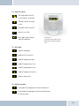
Table of contents
3
Introduction / Preface.................................................................................................... 7
4
Safety notes.................................................................................................................... 8
5
Scope of delivery / package content............................................................................... 9
6
Installation guide............................................................................................................ 10
6.1
Determination of required configuration......................................................................................................10
6.1.1
Vehicle................................................................................................................................................................................. 10
6.1.2
Mobile Telephone................................................................................................................................................................ 10
6.1.3
Muting (radio muting)......................................................................................................................................................... 10
6.1.4
Converting the EGO FLASH into an already-installed Funkwerk hands-free car kit..................................................... 10
6.1.5
Add-on speakers / Car audio telephone connection......................................................................................................... 11
6.1.6
Car audio line-in input........................................................................................................................................................ 11
6.2
Installation locations.....................................................................................................................................11
6.2.1
Checking cable lengths...................................................................................................................................................... 11
6.2.2
6.2.3
Selection of the installation location for the electronics box........................................................................................... 11
Selection of the point of installation for the microphone................................................................................................. 12
6.2.4
Selection of site for installing the control unit with integrated display........................................................................... 12
6.3
Installation.....................................................................................................................................................13
6.3.1
Mounting the electronics box............................................................................................................................................. 13
6.3.2
Mounting the microphone.................................................................................................................................................. 13
6.3.3
Mounting the control unit with integrated display............................................................................................................ 14
6.4
Connection scheme.......................................................................................................................................14
6.4.1
Preface................................................................................................................................................................................ 14
6.4.2
EGO mute cable................................................................................................................................................................... 15
6.5
Installation of the ISO connecting cable.......................................................................................................16
6.5.1
Checking the mute inputs / ISO-Profi................................................................................................................................ 16
6.5.2
Checking the installation.................................................................................................................................................... 19
2
|3
EGO FLASH
6.5.3
Additional external speakers............................................................................................................................................. 19
6.6
Connecting the components to the electronics box......................................................................................20
6.7.
Connection of the EGO iDapter to the electronics box..................................................................................22
7
Operating instructions.................................................................................................... 23
7.1
Features.........................................................................................................................................................23
7.1.1
Overview of features........................................................................................................................................................... 23
7.2
Symbols.........................................................................................................................................................23
7.2.1
Key functions....................................................................................................................................................................... 24
7.2.2
Symbols in the status bar................................................................................................................................................... 25
7.2.3
Speller symbols.................................................................................................................................................................. 25
7.2.4
Symbols for menu options.................................................................................................................................................. 25
7.3
Speller...........................................................................................................................................................26
7.4
Getting started...............................................................................................................................................26
7.4.1
About Bluetooth® technology............................................................................................................................................. 26
7.4.2
On / Off function.................................................................................................................................................................. 27
7.4.3
Enter Bluetooth® PIN.......................................................................................................................................................... 27
7.4.4
Hands-free mode................................................................................................................................................................ 27
7.4.5
Automatic coupling............................................................................................................................................................. 27
7.4.6
Call....................................................................................................................................................................................... 27
7.5
The menus.....................................................................................................................................................29
7.5.1
User management.............................................................................................................................................................. 32
7.5.2
Settings............................................................................................................................................................................... 33
7.5.3
iPod TM Player....................................................................................................................................................................... 35
7.5.4
Music player........................................................................................................................................................................ 36
7.5.5
Contacts list........................................................................................................................................................................ 37
7.5.6
Call lists.............................................................................................................................................................................. 38
7.5.7
Messages............................................................................................................................................................................ 38
7.6
Voice control..................................................................................................................................................39
8
Software update............................................................................................................. 42
9
Service........................................................................................................................... 43
10
Spares parts and accessories........................................................................................ 46
10.1
Anschlusskonzept des EGO Mute Kabel........................................................................................................47
11
Technical data................................................................................................................ 49
12
Certification.................................................................................................................... 49
13
Conformity statement.................................................................................................... 50
14
Hotline............................................................................................................................ 52
4
|5
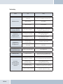
List of illustrations
EGO FLASH
Fig. 01:
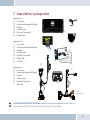
Scope of Delivery..............................................................................................................9
Fig. 02:
Signal transmission of the Bluetooth® antenna...............................................................11
Fig. 03:
Installation locations for the electronics box..................................................................12
Fig. 04:
Installation location for microphone................................................................................12
Fig. 05:
Electronics box dimensions.............................................................................................13
Fig. 06:
Connection for the mini ISO connection cable.................................................................14
Fig. 07:
ISO-Profi box....................................................................................................................15
Fig. 08:
EGO mute cable................................................................................................................15
Fig. 09:
Installation procedure......................................................................................................16
Fig. 10:
Type-dependent pin allocation.........................................................................................17
Fig. 10a:
Plug wiring scheme..........................................................................................................17
Fig. 10b:
Connection system...........................................................................................................17
Fig. 11:
Type-dependent pin allocation (EGO mute cable)............................................................18
Fig. 11a:
Plug wiring scheme EGO mute cable...............................................................................18
Fig. 11b:
Connection system EGO mute cable................................................................................18
Fig. 12a/b:
View after changing cables..............................................................................................19
Fig. 13:
Additional external loudspeakers....................................................................................20
Fig. 14:
Electronics box connection..............................................................................................21
Fig. 14a:
Connection EGO iDapter...................................................................................................22
Fig. 15: Status bar.........................................................................................................................25
Fig. 16:
Connection Concept EGO mute cable...............................................................................47
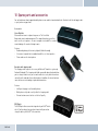
3 Introduction / Preface
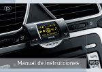
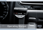
Congratulations on your new EGO!
Whether you’re browsing through your contacts list, reading SMS messages or selecting music for playback – EGO FLASH is a
practical all-rounder with a razor-sharp OLED display and intuitive controls. Its handy size and sleek design make it a must-have
accessory for your car.
The installation of your EGO FLASH in your car requires specialist knowledge and skills. We recommend that the installation be
carried out in a qualified professional workshop.
Before installation in your car, please make sure that your mobile phone is fully compatible with EGO FLASH. If you are uncertain,
please consult your dealer or a professional workshop. Our service team will also be happy to help you with any information you
may require. You can find further information on compatibility between EGO TALK and various mobile phones on our website.
6
|7
4 Safety notes
1.
Incorrect installation – Incorrect installation may lead to damage to the units and/or your car! Specialized knowledge
and skills are required for installing the system. We strongly recommend that the system be installed by a qualified
professional.
2.
Risk of injury – Unsuitable installation locations may become a source of injury in an accident situation, or may inhibit the
correct functioning of essential safety equipment. Please carefully read the notes in the „Installation“ chapter carefully!
3.
Risk of injury/material damage – the removal of vehicle lining with sharp or pointed objects may lead to injuries or
material damage.
4.
Road safety risk – Diverted attention can lead to dangerous situations in traffic. Even when using hands-free phone
systems, your complete attention must be paid to the current traffic conditions. It is always advisable to avoid
phone calls while driving in difficult traffic situations!
5.
Damage to airbags – An incorrect installation location may cause damage to, or inhibit the correct function of, your
airbags. Do not install the components within the deployment area of the airbags!
6.
Insulation damage – Damaged insulation can lead to equipment and wiring damage. The cables and leads may not be
under tension when installed. Install the cables and leads in such a way as to avoid pinching or abrasion.
7.
Polarity and shorting damage – Cables connected with reversed polarity, or in such a way as to produce a short
circuit, can lead to serious damage to your equipment. Before commencing installation, make sure that the car
battery is disconnected.
8.
Damage to essential vehicle components – Essential vehicle components or wiring can be damaged when drilling
mounting holes or screwing in self-threading screws. Please make sure there is always sufficient space behind the
screw holes and drilled holes!
9.
Interference with on-board electronics – Despite the extreme protection against interference, incorrect installation can
lead to interference with the vehicle electronic systems. Please read the vehicle manufacturer’s notes to this effect!
10. Appropriate use – The EGO FLASH is intended exclusively for use in vehicles with Bluetooth® mobile phones and A2DP
devices.
EGO FLASH
11.
Damage caused by inappropriate replacement parts – Inappropriate spare or replacement parts may lead to
malfunctions. Please use only the approved parts listed in the section „Spares parts and accessories“!
12.
Road safety risk – For your own safety, never initiate the coupling procedure while your vehicle is in motion!
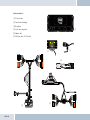
5 Scope of delivery / package content
Supplied version 1
[1]
[2]
[3]
[4]
[5]
[6]
Electronics box
Control unit with integrated OLED display
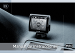
Microphone
Self-adhesive pad
Quick Guide / Safety manual
ISO adapter cable
[3]
[1]
Supplied version 2
Supplied version 3
[1]
[2]
[3]
[4]
[5]
*
[4]
Electronics box
Control unit with integrated OLED display
Microphone
Self-adhesive pad
Quick Guide / Safety manual
EGO mute cable
ISO-Profi box
Electronics box
Control unit with integrated OLED display
Microphone
Self-adhesive pad
Quick Guide / Safety manual
without cable
[2]
Funkwerk Daben
[5]
QUICK
GUIDE
Safety Instructions
129 8011 1.02
Welcome
[6]
Telephone
Fax
E-mail
Internet
A Funkw erk
316-2 33
+49 (0) 33 77
316-3 00
+49 (0) 33 77
line.de
info@f wd-on
line.de
www.f wd-on
AG company.
9
ID B01293
Improper installation –
Bluetoo th QD
Improper installation may
cause damages to the unit
abilities. We therefore strongly
or to the vehicle! The installati
recommend to have the installati
on of the hands-free car kit
requires spezial knowledge
on one by a professional.
and special
2. Persona l injury – Inapprop
riate places for the installati
on may cause personal injuries
“Installation”!
in taccidents or may disable
cep
the safety equipment. Note
Connection Con
the directions in the chapter
3. Persona l injury / Material
Dabendorf.
Funkwerkdamage
–
from
When
ct
you remove coverings or armature
ing a produ
p of EGO
choosDon’t
submit gh
parts, sharp tools may cause
initial set-u
thethe
connecti
Thank you for
ng cables tofor
personal injuries or material
pressure.
takes you throu
damage. Remove the parts
ting instructions
This Quick Guide
carefully.
using the opera
4. mend
with
Negative
effectsfamil
yourself
on road
iarizesafety
FLASH. We recom
– Talking
whilst driving reduces your
lation
(or similar) to
phoneyour
concentration. This may cause
before instal
attentione make
your cellul ar
to the sure
traffic.
In complex traffic situation
dangerous situations on the
® functions. Pleas
s
road. Also in hands-free mode,
you
ooth
should refrain from using
the Bluet
with the unit.
the mobile phone!
you should draw
is compatible
can be
5. Damage
phone
ctions
of
cell
the
instru
airbag
the
that
operating – A wrong place selected for the
and detailed
installation of the compone
nts fwd-o
More informationcompone
nts may cause damage to
out ofnline.
rangede.
33.
of action
of the316-2
the air bag or impair the function
air bag!
website at www.
+49 (0) 3377
found on our
ing of the air bag. Install
our hotline at
the
6. questions, call
If you have any Insulation damage – Damaged insulatio
ns may cause damages of
the unit. The cables installed
pinched or chafed.
should not be exposed to
tensile stress. Install the cables
such as they are not
7. Damage caused by polarity
ctor
Baseplate conne er
reversal or short circuitin
ction
charg
ed
g
–
Conne
Incorrectly connected cables
for mount
the car battery before you
or a short circuit may cause
cable
al)
begin installation.
for ISO
serious
damage to the(option
equipment. It is essential
EGO FLASH
to disconnect
8. Damage of importa
nt vehicle components –
Drilling mounting holes or
box
driving in self-tapping screws
- Electronic s there is enough
space left also behind the
may cause damage to importan
screws und drilling holes!
with display
t vehicle components or to
Connection
- Control unit
cables. Make sure
Connection,
9.UTE
Effects on the vehicle’s
for EGO FLASH
ADIO
le
- Microphone
vehic
electrica
e.g.
the
l system – Although the hands-fr
display
connecting to
ee car kit produces
electroni
ISO cable for
-I S
MP3 playerlow amounts
c equipment of the car. Note
O-PROFI
of radiation, improper installati
the directions of the vehicle
on of the hands-fr
- Adapter cable
manufacturer!
ee car kit may influence the
Connection
10.ive Proper
pad
ISO connection
use – This system is intended
for the
- Adhes
ISO connection
for use exclusively with mobile
to car radio
Box
e
Stereo Mute
Line out
for the vehicl
phones
- Quick Guide
in motor vehicles.
Microphone
ction,
11.
ation
Damage
cable loom
conne
inform
s
caused
y
ction
by false replacement parts
- Safet
– False replacement partsconne
e.g. car radio
may cause disturba nces. Only
Accessories”!
use the replacement parts
listed in the chapter “Replace
PEAKER
ment parts and
12. Negative impact on
driving safety – For your
own safety, please do not
perform a pairing procedur
e while driving!
1.
EGO FLASH
dorf GmbH
Märkische Straße
dorf
D-158 06 Daben
[7]
Contents
DABENDORFER R
RADIO
brown 31
white Muting out
green
phone
violet
yellow Muting in
30 +12V
red
[1]
[2]
[3]
[4]
[5]
[7]
[8]
M
S
[8]
Fig. 01:
Scope of Delivery
PLEASE MAKE SURE THE CONTENT OF THE PACKAGE is complete. If any parts are missing, please don‘t hesitate to contact our
service hotline team: +49 (0) 3377 - 316 233, Mon.–Thurs 7.15 a.m.–6.00 p.m., Fri. 7.15 a.m.–4.00 p.m.
8
|9
6 Installation guide
6.1 Determination of required configuration
Before installation of your EGO FLASH, please note which features and connection options are provided by your car audio system.
It is advantageous when your audio has the following: a muting function, phone input and line-in. You can find out which of these
input options your audio system has in the documentation provided.
6.1.1 Vehicle
The EGO FLASH may only be installed in vehicles with 12 V, with the negative terminal connected to the chassis. If no car audio is
installed, an add-on speaker will be required. For the installation of the optional charging cradle, you will require a model-specific
mounting that may be purchased from a specialist dealer.
6.1.2 Mobile Telephone
A Bluetooth®-compatible telephone must be available for use with this system. You can find a list of supported Bluetooth® telephones online at www.fwd-online.de.
6.1.3 Muting (radio muting)
The muting function (Radio Muting) ensures that the audio sound is turned off during telephone calls. The system
supports the muting function. Your car`s audio documentation will show whether your car audio has a mute option. If your car audio is not equipped with a muting option, you can install the optionally available Stereo Mute Box to facilitate speaker muting.
6.1.4 Converting the EGO FLASH into an already-installed Funkwerk hands-free car kit
An adapter cable is available for customers who already own a Funkwerk hands-free car kit (including the Audio 2000, 3000, Audio
blue, Audio com, and Audio compact) and who would like to easily convert the EGO FLASH. The adapter cable connects the ISO
cable, already installed in the vehicle, of your previous Funkwerk handsfree system with the EGO FLASH and is available as an
accessory.
EGO FLASH
NOTE! This simple converting option is only possible when installing the EGO FLASH without a stereo mute box. To install the EGO
FLASH with the stereo mute box, the stereo mute box’s ISO connecting cable should be used to connect to the vehicle.
6.1.5 Add-on speakers / Car audio telephone connection
The car’s loudspeakers are transferred to the system is by means of switch contacts. These are designed for a peak power handling of 35 W (Sinus). Loudspeaker power handling exceeding 35 W leads to premature wear on the switching contacts. For higher
outputs, use the telephone connection of the car audio or a 5 W / 4-Ohm satellite speaker. This port is only designed for voice
reproduction.
6.1.6 Car audio line-in input
A car audio with a line-in input option is required for music reproduction in stereo. As an alternative to line-in, the car audio may
have a mini-ISO port (block connector C), a 0.14 in jack socket or a RCA input socket. An appropriate adapter lead is required for
the connection between the EGO FLASH line-out and the line-in version of your audio system. If your car audio system has no
line-in option, you can employ the optionally available Stereo Mute Box for stereo reproduction in combination with your car’s front
speakers.
6.2 Installation locations
INSTALLATION LOCATIONS! Unsuitable installation locations may become a source of injury in an accident (or emergency braking)
situation, or may inhibit the correct functioning of essential safety equipment!
6.2.1 Checking cable lengths
Before you’ve securely installed the components, check that the installation locations have been selected in such a way that the
cable length is sufficient to connect the individual components.
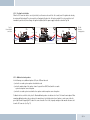
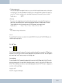
6.2.2 Selection of the installation location for the electronics box
The Bluetooth® antenna for the connection to the mobile phone is
installed in the electronics box. The antenna transmits directionally
towards the front. For this reason, during installation, ensure that the
antenna faces into the passenger cell (see Fig. 02). Vertical mounting
is ideal. Metallic screening between the front panel and the passenger
cell, such as metal or metallised plastic panels, are unsuitable and may
interfere with the Bluetooth® connection. Locations behind the dashboard or in a metal-lined glove compartment are also unsuitable.
Fig. 02:
Signal transmission of the Bluetooth® antenna
A covering in plastic, fabric or wood presents no problems whatsoever.
10
| 11
Suitable locations for the electronics box:
Passenger side, next to the middle console under the paneling,
model-specific installation console (dealer).
Our suggested installation locations are shown in the illustration on
the right.
Fig. 03:
Installation
locations
for the electronics box
Further unsuitable locations are:
Leg and knee height, potential head impact zone, airbag inflation
space, engine compartment
6.2.3 Selection of the point of installation for the microphone
Suitable for the microphone:
Where voice can reach the microphone unhindered (distance between
the speaker and the microphone should be approx. 13.78 in), on the
A-column (between windshield and driver’s side window), next to the
driver‘s sun visor, on the dashboard
Unsuitable for the microphone:
Close to the speakers (less than 31 in), under the dashboard, in the air
stream from open windows or air vents
6.2.4 Selection of site for installing the control unit with integrated display
Suitable for the control console:
In the space above the DIN installation shaft, close to the steering wheel (in an easily accessible and visible position)
Unsuitable for the control console:
Airbag inflation space, potential head impact zones, out of reach of driver’s reach
EGO FLASH
Fig. 04:
Installation location for microphone
The illustration
shows one of the
potential microphone mounting locations.
Alternatively, the
microphone may
be attached to the
sun visor with the
clip provided.
6.3 Installation
DAMAGE TO ESSENTIAL VEHICLE COMPONENTS! Essential vehicle components or wiring can be damaged when drilling mounting
holes or screwing in self-threading screws. Please make sure there is always sufficient space behind the screw holes and drilled
holes!
6.3.1 Mounting the electronics box
Installation consoles for a number of car models are
available from your dealer. These are designed to contain all the system components, including the electronics
box. When it is not possible to use an installation console,
please proceed as follows:
Fig. 05:
Electronics box
dimensions
Define the mounting points
Making sure that there is at least 2.8 in space for the plug
and socket connectors. Mark the positions for the fixing
screws.
Mounting the electronics box
For mounting the electronics box, use four self-threading screws and appropriate washers. We recommend size “ST 2,9x25 DIN
7981” self-threading screws. These are ideal for the fixing of the electronics box. Pre-drill the holes with a 0.08 in drill.
6.3.2 Mounting the microphone
Define the mounting location
The microphone holder has a self-adhesive strip on the back. The mounting location should have the same form and area as the
self-adhesive strip on the microphone holder. The location selected must allow the microphone cable to reach the electronics box!
Position the microphone with the head facing towards the direction of speech.
Cleaning and degreasing the mounting location
The mounting location must be clean and free from grease and dirt/dust. Prior to installation, clean the area with a cleansing product containing ethyl alcohol. Only use products that do not damage plastics or varnished wood finishes and are themselves free of
oils or grease. Unsuitable cleansers are, for example, lighter fluid, acetone, turpentine, trichloroethylene and similar products.
Attaching the microphone holder
Peel off the protective backing from the self-adhesive strip. Hold the microphone holder at a distance of several millimetres (about
a quarter of an inch) above the desired mounting location. Re-check the positioning. Re-positioning after mounting is no longer
possible. Place the microphone holder on the mounting location and fix by applying short and light pressure.
12
| 13
Attaching the microphone
Attach the microphone by sliding it into the holder and position the microphone head towards the direction of speech.
6.3.3 Mounting the control unit with integrated display
Define the mounting location
The control console is mounted on a smooth service by means of the self-adhesive pad provided. Make sure that the location is
within easy reach of the intended user.
Cleaning and degreasing the mounting location
The mounting location must be clean and free from grease and dirt/dust. Prior to installation, clean the area with a cleansing product containing ethyl alcohol. Only use cleansing products that do not damage plastics or varnished wood finishes and are themselves free of oils or grease. Unsuitable cleansers are, for example, lighter fluid, acetone, turpentine, trichloroethylene and similar
products.
Attaching the control unit with integrated display
After defining the appropriate cable direction on the back of the console, fix it by covering it with the self-adhesive pad. Hold the
control console at a distance of several millimetres (about a quarter of an inch) above the desired mounting location. Re-check the
positioning. Re-positioning the console after mounting is no longer possible. Apply the control console to the proposed mounting
location and fix by applying short and light pressure.
6.4 Connection scheme
6.4.1 Preface
Installation for call reception for a car audio system with a mute input but without a phone input
With this connection option, voice playback is is emitted from the front right car speaker.
During calls, the mute input blocks the car audio signal.
NOTE: Please observe the information in section “6.5.1 Checking the mute inputs” on connecting the mute lead of the ISO connecting cable.
Installation for voice playback with a car audio system with phone and mute input options
With this connection option, voice playback comes through the car audio system speakers.
During calls, the car radio output is switched to the phone input by the mute input In order
to access the phone input of your car audio system, the speaker output of your EGO FLASH
must be connected to the phone input of your car audio system. The purple and green leads
of the ISO cable must be connected to the car audio phone input for this option. The purple
and green leads must be disconnected from the ISO connector. The green lead (pin 14 of
EGO FLASH
Fig. 06:
Connection for the mini
ISO connection cable
the 14-pin plug) should be connected to „Phone Out“, and the purple lead (pin 7 of the 14-pin plug) to „Phone In +“ of the Mini-ISO
socket. For information on the phone connection options of your car audio system, please consult the manufacturer‘s user manual.
NOTE: If your car audio system has different phone connection options from those mentioned here, please consult a qualified professional for installation of the system. Furthermore, please read the section with information on connecting the mute lead of the
ISO connection cable, “6.5.1 Checking the mute input”.
6.4.2 EGO mute cable
NOTE: An MP3can be played using Bluetooth via the connection of the line out at the
automobile radio!
Fig. 07: ISOProfi box
For calls with the cell phone in connection with a hands-free system in the automobile, the loudspeakers of the automobile radio
are switched off by the radio mute change-over. The two front loudspeakers are switched over to the NF output of the hands-free
system and thus used to render the telephone call.
Properties:
- complies with the legal regulations of the consumer protection [CE] (European Directives)
- easily operated hands-free system in each automobile with radio device and at least two loudspeakers
- automatic activation by hands-fee system for every telephone call
- the driver is not distracted by operating the radio
- no installation of additional loudspeakers required for the hands-
free system
Fig. 08:
EGO mute cable
14
| 15
6.5 Installation of the ISO connecting cable
The battery must be disconnected before starting cable installation. Disconnect the grounding cable from the negative pole of the
battery. The cable installation procedure is shown in the illustrations.
Connect 14-pin ISO
connecting cable to
EGO FLASH
Fig. 09:
Installation
procedure
Connect EGO FLASH ISO
connector to car radio
Car audio
Car audio
Electronics box
Disconnect car wiring
harness from car radio
2
1
3
Connect yellow mute lead to
one of the three mute inputs
(see table)
Connect EGO FLASH ISO connectors to car
wiring harness ISO connectors
4
When the installation is completed, reconnect the grounding cable to the negative pole of the battery.
6.5.1 Checking the mute inputs / ISO-Profi
Picture 5 of Fig. 09 shows mute inputs 1–3. The yellow mute lead of the hands-free system should be connected to one of these
inputs. Which mute input should be selected is shown in the tables:
EGO FLASH
Volkswagen,
Grundig
Radio model
Ford,
Mercedes,
Porsche,
Becker
Radio model
Blaupunkt
Radio model
Philips
Pin
1
2
3
4
7
8
Pin
1
2
3
4
7
8
Pin
1
2
3
4
7
8
Mute
blue
Ignition (15)
red
Permanent positive (30)
brown
Ground (31)
Socket wiring from
Plug wiring from
the rear (see table)
the rear
Socket contact housing
Wire colour
Function
Mute
red
Permanent positive (30)
blue
Ignition (15)
brown
Ground (31)
Fig. 10b:
Connection system
Socket contact housing
Wire colour
Function
Mute
red
Permanent positive (30)
blue
Ignition (15)
brown
Ground (31)
Socket contact housing
Wire colour
Function
Mute
red
Permanent positive (30)
blue
Ignition (15)
brown
Ground (31)
Vehicle wiring harness
Audi,
Pin
1
2
3
4
7
8
Fig. 10a:
Plug wiring scheme
Wiring of power supply connectors
Car audio
Radio model
Socket contact housing
Wire colour
Function
Electronics box
Fig. 10:
Type-dependent
pin allocation
16
| 17
Volkswagen,
Grundig
Radio model
Ford,
Mercedes,
Porsche,
Becker
Radio model
Blaupunkt
Radio model
Philips
EGO FLASH
Pin
1
2
3
4
7
8
Pin
1
2
3
4
7
8
Pin
1
2
3
4
7
8
Mute
blue
Ignition (15)
red
Permanent positive (30)
brown
Ground (31)
Socket wiring from
Plug wiring from
the rear (see table)
the rear
Socket contact housing
Wire colour
Function
Mute
red
Permanent positive (30)
blue
Ignition (15)
brown
Ground (31)
Socket contact housing
Wire colour
Function
Mute
red
Permanent positive (30)
blue
Ignition (15)
brown
Ground (31)
Socket contact housing
Wire colour
Function
Mute
red
Permanent positive (30)
blue
Ignition (15)
brown
Ground (31)
Fig. 11b:
Connection system
EGO mute cable
Vehicle wiring harness
Audi,
Pin
1
2
3
4
7
8
Fig. 11a:
Plug wiring scheme
EGO mute cable
Wiring of power supply connectors
Car audio
Radio model
Socket contact housing
Wire colour
Function
Electronics box
Fig. 11:
Type-dependent
pin allocation (EGO
mute cable)
ISO-Profi
6.5.2 Checking the installation
When the ISO connection cable is correctly installed, a call remains active until the call is ended, even if the ignition has already
been turned off beforehand. The system switches off automatically when the call has been ended. If the system switches to off
immediately switches off,then exchange the ignition lead (blue) with the power supply lead (red) as shown in Fig. 12b
red
blue
red
red
blue
blue
2A
red
+12V
1A
+12V
red
2A
+1 2V
Fig. 12a:
View of original
connection
blue
blue
Fig. 12b:
View after
changing cables
1A
blue
red
6.5.3 Additional external speakers
In the following cases, additional speakers (4 Ω, min. 5 W) must be used:
→ when the car audio system speakers should not be used
→ when the output rating of the speaker channel is greater than 35 W (Sinus) and the car audio
system has no phone connection option
→ when the car audio system is used with active speakers and has no phone connection option
Feedback interferes with the clarity of calls. Mount additional speakers at a distance of at least 31 in from the microphone. When
mounting additional speakers, please observe the manufacturer‘s installation instructions. Speakers can be connected to the
green (pin 14) and the purple (pin 7) leads of the connection cable. First of all, the purple and green leads must be disconnected
from the ISO connector (see Fig. 13).
18
| 19
Fig. 13:
Additional external
loudspeakers
Pin
1
2
3
4
5
Colour
Brown
Yellow
Function
Ground (31)
Radio mute
6
White
Car audio speaker
output +
(front right)
7
Purple
Speaker lead +
(front right)
8
9
10
11
12
Red
Blue
Permanent positive (30)
Ignition (15)
13
Black
Car audio speaker
output (front right)
14
Green
Speaker lead (front right)
View of the plug side,
Connection option for additional speakers on pin 7
from which the wiring is
(purple lead) and pin 14 (green lead) of the 14-pin plug
fed in the plug housing
(with pin allocation)
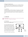
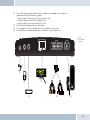
6.6 Connecting the components to the electronics box
The individual components are connected to the electronics box as follows :
[1] Plug the microphone jack into the jack socket with the microphone symbol
[2] The electronic box line-in can be used to connect an optional MP3 player with line-out. To do so, a connection
cable 0.14 in stereo jack plug to 0.14 in stereo jack plug (l = 4.92 ft) is required.
EGO FLASH
IMPORTANT: Only connect the device (MP3 player, iPod™, etc.) to the electronics box line-in with a jack cable when it is being powered by battery alone (without the recharger), as interfering impulses may otherwise cause damage to the electronic box line-in.
[3]
[4]
[5]
[6]
The electronics box line-out must be connected to the car audio line-in. Depending on the car audio line-in
configuration, one of the following cables is required:
→ Connection cable 0.14 in stereo jack to 0.14 in stereo jack (l = 4.92 ft)
→ Connection cable 0.14 in stereo jack to RCA plug (l = 4.92 ft)
→ Connection cable 0.14 in stereo jack to Mini-ISO (l = 4.92 ft)
The control unit with display must be connected to the port.
The 14-pin plug of the ISO connecting cable must be connected with the electronics box.
The base plate for the charging cradle may also be connected to the “charger” output socket.
Fig. 14:
Electronics box
connection
[1]
[4]
[2]
[3]
[5]
[6]
20
| 21
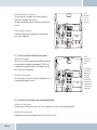
6.7. Connection of the EGO iDapter to the electronics box
Before the EGO iDapter is connected to the Ego Look/Flash, a Bluetooth update to software version 8.1 or higher must be performed. Following this, the EGO iDapter can be attached to the Ego Look/Flash as described in the connection diagram.
Fig. 14a:
Connection
EGO iDapter
iPod Player
EGO FLASH
7 Operating instructions
ROAD SAFETY RISK! Failure to pay attention can lead to dangerous situations in traffic. You must always direct your complete attention to current traffic conditions, even when speaking with a hands-free device. It is advisable to avoid phone calls while driving
in difficult traffic situations!
NOTE: Depending on the software, individual functions may not be available! For more information, visit www.fwd-online.de.
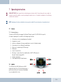
7.1 Features
7.1.1 Overview of features
The hands-free EGO FLASH system supports the Bluetooth® hands-free profile. The EGO FLASH is the practical
all-rounder for phoning in the car and offers the following range of functions:
→
→
→
→
→
→
→
→
→
→
Call functions, such as incoming/outgoing calls and redial
Integrated voice control
Intuitive voice dialing directly from your mobile phone’s contacts list (without training)
Activate and use the voice dialing of the mobile phone
Allows users to read and reply to SMS messages
iPodTM player
Contacts list and call lists
Music player – replay of music files on mobile phones, iPodsTM or MP3 players via
Bluetooth® Audio Streaming (A2DP)
Automatic radio muting
Can be buddied with up to 10 mobile phones
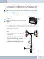
7.2 Symbols
The control unit of the EGO FLASH features an OLED
display and a total of 6 keys. The illustration below gives a
quick overview of the keys. The functions of the individual
keys are explained in this section.
22
| 23
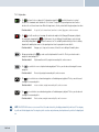
7.2.1 Key functions
→ The
key (green) is for accepting calls. Prolonged pressing of the
key will also launch voice control.
Possible voice commands can be found in the “Voice control” chapter of these operating instructions. Another
function is the selection of menu items. When listening to music, this key controls both the play and pause functions.
Functions in brief:
→
Accept call, select menu items, launch voice control, play, pause, end screensaver
The
key (red) is used to reject incoming calls and to end completed calls (hang up). During music playback,
the song may be stopped with the
key. Furthermore, the voice dialing of the mobile phone can be activated and used by holding down the
button in the main screen. The availability and functionality of the voice dialing depend on the mobile phone used. See the operating instructions for your phone for more details.
Functions in brief:
Hang up, reject, stop, end screensaver, Activate the voice dialing of the mobile phone
→ During music playback, the
navigate the menu and speller.
Functions in brief:
key can be used to skip forward to the next title. This key can also be used to
Skip forward to next title, navigate menu and speller, end screensaver
→ The
key controls the reverse-skip function during playback. This key can also be used to navigate the menu and speller.
Functions in brief:
Reverse skip, navigate menu and speller, end screensaver
→ The
key is used to increase volume during a phone call and during music playback. This key can also be used to navigate the menu and speller.
Functions in brief:
increase volume, navigate menu and speller, end screensaver
→ The
key is used to decrease volume during a phone call and during music playback. This key can also be used to navigate the menu and speller.
Functions in brief:
EGO FLASH
Reduce volume, navigate menu and speller, end screensaver
NOTE: The EGO FLASH features a screen saver. After 60 seconds of inactivity, the display automatically switches off. Pressing any
key will switch the display back on. Pressing a key in this case does not perform any function, but merely switches the display back
on.
7.2.2 Symbols in the status bar
Field strength symbol – indicates the
current strength of the reception field
SMS symbol – indicates text messages
received
Arrow symbol – indicates missed calls
FWD
Indicates the user’s initials
Battery symbol – indicates the battery
capacity of the mobile phone
Fig. 15: Status bar
The status bar is located in the upper area of the
display and shows the symbols described in this
section.
7.2.3 Speller symbols
Symbol for confirming input
Symbol to delete the last character
Symbol for changing to numeric input
Symbol for changing to lowercase letters
Symbol for changing to uppercase letters
Symbol for changing to special characters
Symbol for exiting the speller
7.2.4 Symbols for menu options
Activated option. This symbol appears in front of an activated menu item.
Deactivated option. This symbol appears in front of a menu item when it may
be activated as an option.
24
| 25
7.3 Speller
The EGO FLASH is controlled with the
,
keys. The
key is used to confirm a selection, and the
key quits the
speller. The speller allows phone numbers or names to be composed from individual letters or numbers. It is available for various functions of the EGO FLASH, such as for dialing a phone number or to create a contacts list entry. Operation of the speller is
explained below:
→
Entering numbers
Navigate by pressing the
,
keys to reach a specific number and accept it by pressing the
key. You may
delete the last numeral entered by pressing the
symbol. Once the complete number has been entered, it can be dialed by pressing the
symbol. To quit the speller, press and hold the
key.
→
Entering names or text
As with entering numbers, you can use the speller to enter names or text. Navigate by pressing the
,
keys to reach a specific letter and accept it by pressing the
key. You may delete the last letter entered by pressing the
symbol. Once the name has been completely entered, it can be saved by pressing the
symbol. To quit the speller, press and hold the
key. Switching between uppercase, lowercase and special characters is possible with the symbols described in Chapter 7.2.3, which can be selected with the
,
keys.
7.4 Getting started
Take enough time to familiarize yourself with the use of the EGO FLASH in combination with your mobile phone. First of all, make a
few calls to determine the ideal volume and the best voice pickup direction before using the EGO FLASH in traffic.
When getting started, your car should be parked in a quiet place. It is also helpful if the person you will be calling can take time to
let you make some test calls.
7.4.1 About Bluetooth® technology
Bluetooth® technology is a wireless technology and, as such, it allows communication between individual devices without the need
for cables. Data and voice information can be transmitted simultaneously. It is unnecessary to have line-of-sight routing between
the devices. The transmission/reception range in the open is typically 33 feet. Interference from other electrical or electronic
equipment or obstacles may, however, reduce this range. The frequency band, in which Bluetooth® operates, is reserved virtually
worldwide. This, coupled with the fact that each Bluetooth® product is tested and approved for compatibility with other Bluetooth®
devices, ensures the highest possible levels of compatibility with devices from a wide range of manufacturers. The EGO FLASH
system supports the Bluetooth® hands-free profile. This means that it is fully compatible with all phones supporting the Bluetooth®
hands-free profile. If you are uncertain, read the operating instructions for your mobile phone to see which profiles are supported.
A2DP (Advanced Audio Distribution Profile) is a technology that enables the wireless transmission of stereo audio signals via Bluetooth® to a compatible receiving device. Please take a look at our homepage for information about compatible mobile phones.
EGO FLASH
7.4.2 On / Off function
The first time you use your EGO FLASH, you must start the EGO FLASH by turning the ignition key. You will see the starting logo
and the main display screen. If no connection to a mobile phone exists or no user is found, the functionality of the main menu is
restricted.
In order to connect to the EGO FLASH, you must select the “User management” menu item with
. “New user” is then selected. The EGO FLASH will then search for mobile phones within its range of reception. If it fails to find your mobile phone, you
may repeat the search, or read the section on “Troubleshooting”. When the name of your mobile phone is shown, select it with
the
key. After a connection is established with the EGO FLASH, the main menu is fully functional. Functionalities that are not
supported by the mobile phone are not selectable. If the ignition is switched off, the EGO FLASH shuts itself off. If the ignition is
switched off during a phone call, the call continues without interruption. The EGO FLASH will shut itself off only after the phone
call is ended.
7.4.3 Enter Bluetooth® PIN
After a few seconds you will be prompted to enter your Bluetooth® PIN. Enter the PIN shown on the EGO FLASH display onto your
mobile phone.
7.4.4 Hands-free mode
In some cases, coupling with your mobile phone in the hands-free mode does not work when using the method described above. If
you are sure that your mobile phone supports the Bluetooth® hands-free profile, proceed as follows: In the list of detected devices,
select “couple from phone”. Now you need to search for Bluetooth® devices using your mobile phone. The procedure for this can
be found in the operating instructions for your mobile phone. The mobile phone will then start searching for devices. Select the
EGO FLASH from the list of devices found by your mobile phone. During the coupling process, your mobile phone will prompt you
to enter a PIN or password. At this point, please enter the series of numbers shown on the display of the EGO FLASH. After a short
time, the mobile phone should inform you that coupling was successful. You may also cancel the coupling at any time by pressing
the
key. If coupling fails, please read the section on “Troubleshooting”..
7.4.5 Automatic coupling
If the phone is already connected with the EGO FLASH, the EGO FLASH will try to couple to this phone. If the search is successful,
a connection is automatically established. A search is always performed for the most recently connected mobile phone.
If the search process was unsuccessful, it‘s possible that Bluetooth® or the mobile phone is not turned on, or that you were not the
last user. If you would like to select another user, activate user management and log this user in.
7.4.6 Call
If there is an existing Bluetooth® connection between the EGO FLASH and a mobile phone, you can use the hands-free function of
the EGO FLASH. If there is no connection, you cannot use the hands-free function. You must first establish a Bluetooth® connection. You may dial a number with voice-activated dialing, through the menu or directly on the mobile phone.
26
| 27
Incoming call
If the mobile phone is available over the Bluetooth® connection, the call is signaled with the ringtone on your mobile phone. Otherwise a signaling tone is generated by the EGO FLASH.
If the caller has not blocked display of his phone number, and if the mobile phone supports this function, the display of the control unit will show the caller’s number or, if a corresponding entry is found in the contacts list, the caller’s name. You can decide
whether to take the call (green key or
key) or reject it (red key or
key). If you accept the call, you can adjust the volume
with the
,
keys. The settings are saved. You can end the call by pressing the
key.
Call setup
Call setup from the EGO FLASH is only possible if there is an existing Bluetooth® connection between the EGO FLASH and the mobile phone. You may set up a call with voice-activated dialing or through the menu.
To activate voice-activated dialing, press the
key for longer than half a second. With the “Dial number” command, you may
announce the number to be dialed, and with the “Dial <name>” command, a name from the contacts list can be dialed directly. For
more details, please see the section “Voice control”.
The following methods may be used to initiate a call from the menu:
→
→
→
→
by selecting from the contacts list and the mobile phone
by direct outward dialing of a number with the number speller
dialing from the call list on your mobile phone
through the call-back feature for received SMS messages.
And lastly, you may also dial a number directly on your mobile phone.
Starting the voice dialing of the telephone
The telephone‘s own voice dialing, if present, can be started by holding down the red button This can be ended again by pressing
the red button again.
IMPORTANT NOTE: Please observe your country’s regulations on in-car telephone use!
Call ended
Once a call is ended, the menu jumps back to the main menu. If an incoming call is rejected with the
the previous menu.
Setting the volume
The replay volume may be adjusted during a call and during active voice recognition with the
EGO FLASH
,
key, the menu jumps to
keys.
TIP! If the person you‘re speaking with cannot hear you well, consider increasing the sensitivity of the microphone in the “Audio”
menu under “Settings”. There is a risk, however, that this may produce annoying echoes.
Options during phone calls
The following options may be activated during a phone call by pressing the
key:
→ DTMF tones
→ Mute mic.
→ Private mode
→ DTMF tones
Here, touch key tones are selected and then sent by means of the speller.
→ Mute mic.
With this option, the microphone can be switched to mute. The person you have been speaking with can then no longer hear you.
Pressing again deactivates the muting of the microphone.
→ Private mode
During a phone call, you may switch to private mode by selecting the “Private mode” menu item and pressing the
key.
Conversation is now possible only via the mobile phone. At this moment, communication via the EGO FLASH is prevented, and the
other occupants in the car cannot hear the conversation. Pressing the
key again quits private mode.
IMPORTANT NOTE: In most countries, phoning while driving is only allowed when using a hands-free system!
7.5 The menus
Use the
,
keys to navigate menu items. Select a menu item with the
key or quit the menu with the
key. Select
the submenu of the current menu by once again pressing the
key. The following menu items may be selected and are listed in
the following menu overview:
→ User management
User-specified settings such as “change initials”, “log in”, “log out”, etc., can be set out under this menu item. New users can also
be logged on. For details, please see the “User management” chapter.
28
| 29
→ Settings
General settings for the EGO FLASH can be entered under this menu item. These range from “Ringtone” to “Software update” to
“Voicemail”. The exact breakdown can be found in the following overview, which depicts the menu structure. You can find more
information in the “Settings” chapter.
→ iPodTM player
The „iPodTM player“ menu offers the option of controlling the iPodTM via the Ego system. Under Options, you can search in various
track lists as usual with iPodTM. See the „iPodTM player“ chapter for more information.
→ Music player
The “Music player” menu allows you to playback songs and to control them as usual with Play, Pause, Stop, Forward, and Reverse.
The playback device can be coupled to the EGO FLASH under “Options”. For details, see the “Music player” chapter.
→ Contacts list
The contacts list contains the entries downloaded from the mobile phone. Each number in an entry can be accessed. In addition,
direct outward dialing is possible here (without voice control). You can find more information in the “Contacts list” chapter.
→ Call lists
Contains lists of the last number dialed, calls received, and missed calls. You can highlight an entry with the
call the number with the
key. For more information, please see the “Call list” chapter.
,
keys and
→ Messages
Contains the list of text messages (SMS). Unread messages are marked accordingly. The messages menu is divided into “Read
messages” and “New message”. More information can be found in the “Messages” chapter.
EGO FLASH
Main menu structure for the EGO FLASH
User management
Settings
Contacts list
Call lists
New user
Playback
→
Search
→
Missed
→
User 1
- Melody
- Pause
- Play
→
Options
→
Accepted
- Change initials
- Volume
- Stop
- Pause
- Direct dialing
→
Dialed
Options
- Stopp
- Synchronization
- Log in
→
User 2
→
Messages
→
Read message
- Read aloud
- Call back
- Answer
→
Brightness
- Brightness
- Playback list
- Forwards
- SIM
→
Call settings
- Artists
- Reverse
- Telephone
- Template 1
- Autom. call acceptance
- Albums
Options
- SIM & telephone
- Template 2
- Log out
- Delete
→
Playing
Music player
→
→
Ringtone
iPodTM Player
→
→
- Change initials
→
Power-off delay
- Tracks
- New device
→
Entry 1
- Log in
→
Reset
- Genres
- Device 1
→
Entry 2
- Log out
→
Software update
- Composers
- Connect
→
...
- Delete
→
Information
- Settings
- Disconnect
→
Entry ...
→
...
→
Language
→
User 10
→
Voice control
- Connect
- Disconnect
- Microphone sens.
- ...
- Device 2
- Language
Audio
New message
- Delete
- Activate
→
→
- Delete
- Device ...
- Line in
- Telephone
announcements
- Mute delay
- Reset
→
Switch off
30
| 31
7.5.1 User management
Symbol:
The EGO FLASH allows you to manage up to 10 user profiles; you can quickly and easily switch between these profiles while using the
EGO FLASH. Individual information saved for each user includes the following:
→
→
→
→
→
→
Contacts list
Display brightness
Ringtone
Display language
Volume settings
Call lists
Opening user management
To enter user management, go to the
symbol in the main screen display and press
. You will then see the user with which the
EGO FLASH established coupling, and the “New user” menu item. If no user is coupled, only the “New user” item appears.
Add new user
To register a new user, you must select the “New user” item with the
same as those shown in the “Getting started” chapter.
Change user’s initials
Open user management. Then select a user and press
the speller, you can now edit the name of the user.
,
keys and press
. The remaining steps are the
. You then reach a submenu. There, select the “Change initials” item. Using
Reset user
To delete all user information, open user management. Select the user you want to reset. Confirm your selection by pressing the
key. A menu then opens. Select “Delete” in this menu. All data for this user is now deleted from the EGO FLASH.
Switch user
To switch users, go to “User management” and select the desired user. Confirm your selection by pressing the
key. A submenu
then opens. Select “Log in” in this menu. If the selected user can be found, the users are switched immediately. If the user cannot be
found, the menu jumps back to “User management”.
Log out user
You can disconnect the current Bluetooth® connection within “User management” under the current user with the “Log out” menu item.
EGO FLASH
7.5.2 Settings
Symbol:
The “Settings” menu is highly complex, since many settings for the EGO FLASH can be carried out under this menu item. The following settings can be carried out:
→
→
→
→
→
→
→
→
→
→
→
Ringtone
Brightness
Call settings
Delay time
Reset
Software update
Info
Language
Voice control
Audio
Switch off
Ringtone
The “Ringtone” menu is subdivided into “Melody” and “Volume”. Under “Melody”, multiple ringtones are available, which can be set
according to personal preference. The “Volume” of the ringtones can be set with the
,
keys.
Brightness
The brightness of the display can be adjusted here to the needs of the user.
Call settings
→ Automatic call answer
If this option is activated, incoming calls are automatically answered after three rings.
Delay time
You may determine how long the EGO FLASH should remain active after switching off the ignition. The delay time may be set in
steps between 0 and 30 minutes.
Reset
This resets all settings back to the standard factory settings. In doing so, all user settings including the contacts list are lost.
32
| 33
Software update
The software for your EGO FLASH can be updated via Bluetooth®. For more details, please see the section “Software update”.
Info
Provides information about the various software and hardware versions of your EGO FLASH. Use this information when you
contact our service department with questions and problems.
Language
The EGO FLASH supports multiple display languages. You can change the display language within this menu item.
Voice control
→ Activate
Carrying out this item launches voice control. Control is performed with specific commands. For more
information see the “Voice control” chapter.
→ Language
If your EGO FLASH features multiple languages, you may select the language here.
Audio
→ Microphone sensitivity
In some circumstances, such as when the microphone is located very far from or very near to the driver, it may be necessary to adjust microphone sensitivity. There are 10 possible levels of sensitivity that may be selected for the EGO FLASH. The sensitivi
ty is shown to the right of the display as a bar. A total of 5 bars can be seen, whereby each bar has two levels. Sensitivity can be adjusted with the
,
keys. Do not set the microphone at too high a level of sensitivity, as this can lead to over-
amplification and poor audio quality for the person you are speaking with.
→ Line-In
In this menu item, you may activate the line in and vary the input volume of the audio device connected to the line
in of the electronics box.
EGO FLASH
Note: Please note that only the connection of an audio device with line level is allowed. If the electronics box’s line in is overamplified through an excessively high signal from the line out of the audio device, the volume must be reduced on the audio device.
→
Telephone announcements
If the connected telephone has navigation functions, here you can set whether the navigation announcements are to be output over the EGO system. The radio is muted during this output. Key tones are also output from the telephone if the telephone ge-
nerates these. The status is saved for every user and returned to the previously set status when the system is restarted.
Possible statuses:
ON/OFF
→
Mutedelay
Here, you can set the waiting time between the activation of the mute line and the voice recognition. This is logical, as car radios require various amounts of time to recognize a mute signal and the switchover of the audio channels in the radio. The time should be set so that the first announcement of the EGO „Main menu“ can be completely heard.
Possible statuses:
0.5 sec. / 1.0 sec. / 1.5 sec. / 2.0 sec. / 2.5 sec. / 3.0 sec.
→ Reset
Resets all audio settings to the default values.
Switch off
The current Bluetooth® connection is severed under this item and the EGO FLASH is switched off. The EGO FLASH may be switched back on by pressing a single key.
7.5.3 iPodTM Player
Symbol:
The iPodTM player is activated via the main menu. The activation can only be performed if the accessory device „EGO iDapter“ was
also purchased. The iPodTM player can also be activated if a mobile phone is not paired with the EGO Flash. To be able to play back
music from the iPodTM an iPodTM must be connected to the EGO iDapter cable.
Connection/pairing
The connection with the iPodTM is automatically performed after the connection to the EGO iDapter cable. If the iPodTM icon in the
main menu remains grayed out, the connection has failed and then you must reconnect the connector of the EGO iDapter cable to
the iPodTM. After establishing a connection, music can immediately be played back from the iPodTM. If the music is stopped, you can
search in the track lists under Options.
Charging the iPodTM
The iPodTM is charged via the EGO iDapter.
34
| 35
Playing
The following functions are available for playing and are shown in the display:
→ Play
→ Pause
→ Stop
→ Forward (track-by-track in the current playlist)
→ Backward (track-by-track in the current playlist)
→ Volume control
7.5.4 Music player
Symbol:
The music player is activated through the main menu. The music player may also be activated without a mobile phone being couple
to the EGO FLASH. In order to play back music, the EGO FLASH must be coupled to an A2DP-capable device (such as a mobile
phone with A2DP, an iPod™ or an MP3-Player with A2DP adapter).
Connection / coupling
Under the “Option” menu item, a “New device” may be coupled, or an already coupled device may be connected. A total of 10 devices may be coupled, whereas only one device may be active. If a “New device” is selected, a Bluetooth® device search is performed. The desired device can be selected from there.
If the music device does not support coupling from other devices, it is also possible to couple the EGO FLASH from the music
device via the “Couple from device” menu item. In both cases, a four-digit PIN code is displayed by the EGO FLASH, which must be
entered into the music device. Is the PIN is incorrect, the menu jumps back to device selection, and you must repeat the process. If
an iPod™ or MP3 player with an A2DP adapter is used, these devices couple automatically with the EGO FLASH. For this, the “Couple from device” menu item must be selected during the search for devices. After coupling, all playback functions are available to
the user.
Playback
The following functions are available for playback and are shown in the display:
→ Play
→ Pause
→ Stop
EGO FLASH
→ Forwards (by title)
→ Reverse (by title)
→ Volume setting (playback volume adjustable in 10 steps)
These functions are controlled with the keys of the control unit. For a description of these keys, please see the “Symbols” chapter.
7.5.5 Contacts list
Symbol:
The mobile phone’s contacts list can be read via the “Contacts list” menu item. In addition to dialing numbers from the contact
information with the
key, entries can be found more quickly with the search function. You may also download the contacts list
from the mobile phone under the “Option” menu item, or enter the number via direct outward dialing.
Read
To read numbers from the contacts list, please select the
menu item. After opening the contacts list, all entries contained in
the list are displayed. Select the number or name you want to call and press the
key. The numbers stored under this name
are then displayed. By pressing the
key once again, the number is dialed.
Search
If searching for a particular name becomes difficult due to a large number of entries, the search function may be used. With this
function, entries may be searched for a specific name or specific first letters. The desired name or first letters can be entered by
using the speller. By pressing the
key, the contacts list will be searched for this name or letter.
Direct dial
Direct dialing is possible in addition to voice-activated dialing. As described under the “Speller” and “Call setup” items, a number
can be entered here by hand using the speller. The call is set up after confirming the number with the
key.
Synchronize
The contacts list from the mobile phone or SIM card can be downloaded to the EGO FLASH unit under the “Synchronize” menu
item. Both contact lists may also be synchronized. Once a contacts list has been selected, it is confirmed with the
key. Now a
loading progress bar is displayed. This signals the current progress of the synchronization process. If downloading is successful,
the entries can be found in the contacts list for the EGO FLASH. It remains possible to cancel the download manually with the
key. If you decide to cancel the process, this must then be confirmed once again at the Yes/No query. With “Yes”, the synchronized
entries are deleted and the menu jumps back to “Contacts list”. At “No”, synchronization is continued.
36
| 37
7.5.6 Call lists
Symbol:
In the “Call list” menu item, you may view “Numbers dialed”, “Missed calls”, and “Calls received”. After selecting the “Call list”
menu item, a list of numbers dialed is downloaded from the mobile phone. “Missed calls” and “Calls received” may also be viewed by selecting the corresponding upper list entries. Some mobile phones do not support access to the call list; in this case, a
call list is maintained within the EGO FLASH.
7.5.7 Messages
Symbol:
The EGO FLASH supports the sending and receiving of text messages. The menu is structured in same form users are familiar
with from their mobile phones. Messages received can be viewed under the “Incoming SMS” item. The sender of the message can
be called back by phone using the “Call-back” function. You may also reply to the sender with a text message (SMS). In addition,
new messages may be recorded.
Various templates are available to you for answering a text message. Select one of these and confirm with the „Send“ button. The
message is sent.
If you do not wish to answer an SMS but rather to send a new SMS, select the „New message“ button. Here you can once again
select a template and then send this. In addition, you can enter the telephone number by hand or select a contact from the phonebook.
You will find the „Read aloud“ item under the SMS text. You have the option here of having the SMS read aloud. You can also activate this function by selecting one of the SMSs shown in the list and holding down the
button.
If the SMS function via Bluetooth is not supported by the mobile phone, then the Messages menu item cannot be selected in the
EGO FLASH.
EGO FLASH
7.6 Voice control
The dialogue-guided voice control of the EGO FLASH allows you to select a name or number via voice input. While numerical selection allows you to directly announce a number, you also have the option to select the name directly from the contacts list.
Language
Depending on the national version of your EGO FLASH, voice recognition supports up to 3 languages, one of which is activated.
To switch the active recognition language, within the menu, select “Setting → Voice control → Language”. A list of available
languages is now displayed. Select the desired language and confirm it by pressing the
button. The EGO FLASH will now save
your settings and will begin updating the recognition language. The status of this process will be displayed with a progress bar.
Activation and sequence
Voice control is only possible when there is no phone call in progress. If under these circumstances the
key is pressed for
longer than a half-second, the “Main menu” standby text sounds, and the display shows the announcement, “Please begin speaking …”.
You may cancel each voice dialogue at almost any time with another prolonged pressing of the
key. If the EGO FLASH is waiting for a voice command, you may end the dialogue by saying “abort”.
If there is no Bluetooth® phone connected to the EGO FLASH, voice-activated dialing cannot be activated.
The following voice commands are possible:
→ “Call / dial <name>”
→ “Call / dial <name>
at home …
at work / in the office / on business …
on the cell phone”
→ “Dial number”
→ “Help”
→ “Redial / call again”
→ “Abort / Cancel”
“Call / Dial <name>”
This command may be used to select a name from the contacts list. The name must be contained in the contacts list for this command to function. If the name is not recognized or found, the EGO FLASH responds with “Please repeat” and offers you the chance
to repeat the command. If the name is recognized, you will be asked if the name should really be dialed. The following commands
are available to you:
38
| 39
→
→
→
→
“Yes / Call / Dial”
“No / Back”
“Abort / Cancel“
“Help”
Dials the number stored under that name
The number for the recognized name is not dialed
Ends the dialogue without carrying out a function
Calls up Help and an explanation of possible commands
“Call / Dial <name> at home … on the cell phone”
With this command, you may dial a specific type of number from a contacts list entry. If the name is recognized, you will be asked if
the name should really be dialed. The following commands are available to you:
→
→
→
→
“Yes / Call / Dial”
“No / Back”
“Abort / Cancel“
“Help”
Dials the number stored under that name
The number for the recognized name is not dialed
Ends the dialogue without carrying out a function
Calls up Help and an explanation of possible commands
“Dial number”
You will be prompted to enter the number to be dialed. This may be done with individual numerals as well as groups of numbers.
If you insert a pause, the last number/group of numbers entered is repeated for checking. In addition, you will be notified if you
exceed the maximum telephone number length. In addition to continuing with the entry of numerals, the following additional commands are available:
→
→
→
→
→
→
→
→
EGO FLASH
„+, *, #, 0, 1, …, 9“ “Delete all”
“Delete / Correct / Change”
“Repeat” “Yes / Call / Dial” “No / Back”
“Abort / Cancel“ “Help”
For entering the number
To delete the entire phone number entered
To delete the last number/group of numbers entered
To announce the entire phone number entered up to this point
To dial the phone number entered
To not dial the number entered
Ends the dialogue without carrying out a function
Calls up Help and an explanation of possible commands
“Help”
As with “Cancel”, this command may be used at any time. If the “Help” command is selected, the EGO FLASH explains which commands are possible for specific functions at the time they are called up.
“Redial / call again”
This command you provides you with the simplest way to redial the most recently dialed phone number. No further dialogue follows. Dialing is only possible when the mobile phone is logged in. An announcement will then inform you when dialing begins.
“Abort / Cancel”
With his command, the current dialogue is ended immediately without any function being carried out.
40
| 41
8 Software update
The software for your EGO FLASH can be updated to the latest version via Bluetooth®. In order to receive the most current software, please visit our website at www.fwd-online.de. A detailed description of the update procedure is included with the software.
EGO FLASH
9 Service
(FAQ) – A list of frequently asked questions:
1. Is it possible to dial directly (without voice control) with the EGO unit?
Yes, with all EGO units except EGO TALK, under the menu item “Contacts list / Options / Direct outward dialing”.
2. What are the exact dimensions of the EGO FLASH components?
You can find the dimensions in the operating instructions under the “Technical data” section.
3. Are EGO units suitable for all types of vehicles?
Yes, EGO units are suitable for all types of vehicles. See installation instructions!
4.
5.
Is there a list of optional charging cradles?
Yes. A list of optional cradles is available on our website.
Are software updates for the units free?
Yes.
6. Where can EGO be purchased?
From authorized specialty dealers. You can find a specialty dealer in your area through our website under the link Dealers → Dealer search.
7.
What is the procedure for transferring data in order to playback music?
With the EGO FLASH, music can be transferred via Bluetooth® (A2DP), via the EGO iDapter and also via the line in. It is possible to make an MP3 player and iPod™ Bluetooth®-capable with a dongle/adapter. If an MP3 player without A2DP is used, a jack cable can be used to connect it to the EGO FLASH.
8. Do EGO units have an external antenna port?
In combination with the optional charging cradle and the associated base plate, the mobile phone can be connected to the
external antenna port.
42
| 43
Troubleshooting:
Problem
Cause
Remedy
No supply voltage
Replace fuse if needed and check cable and connections
Ignition not switched on
Switch on ignition
Ignition line interrupted
Check line and 1A fuse
The microphone is not plugged in
Connect the microphone to the electronics box. If the
cable is defective, replacement is necessary
Air is flowing across the microphone
Mount the microphone in another place or
reduce air flow if needed
The mobile phone is very close to
parts of the EGO FLASH or the car radio
Increase the distance between your mobile
phone and the EGO FLASH or radio
Too little space between
the microphone and speaker
Increase distance or decrease volume
Volume too high
Reduce volume
The mobile phone cannot
find the EGO FLASH during coupling
EGO FLASH is already coupled with a device
Cancel existing connection
Sound is fuzzy or scratchy
Poor Bluetooth® connection
Reduce the distance between the mobile phone and
EGO FLASH or remove (metallic) obstructions if needed
The mobile phone is not within range.
Place the mobile phone within the range of the EGO FLASH
The Bluetooth® interface is
deactivated in the mobile phone.
Switch your mobile phone’s Bluetooth®
to "On" ("Automatic" option is not sufficient)
The mobile phone requires
confirmation of the connection setup.
Confirm the connection on the mobile phone. Deactivate the
security prompt (see operating instructions for the mobile phone)
One of the devices no longer has a valid link key.
Delete the other device from both devices’
list of coupled devices and perform a new coupling.
EGO FLASH won’t switch on
The person you are having a phone
conversation with cannot hear you
The person you are
having a phone conversation
with complains of interference
The person you are
having a phone conversation
with complains of echoes
After switching on
the ignition, the connection
to the coupled mobile phone
is not produced.
EGO FLASH
Problem
iPod TM cannot be connected
to the EGO system
System no longer reacts to
operation
Cause
Remedy
Incorrect connection of the components
Disconnect system from the mains power supply and check
connection, remedy any connection faults
EGO iDapter was not completely initialized
Shut down and restart system
EGO iDapter cable not completely connected
Reconnect cable to iPod TM
Simultaneously press the green button and the „up“ button for longer
than 2 seconds. After a short wait time, the EGO FLASH initializes
itself again
44
| 45
10 Spares parts and accessories
You can find out more about supported mobile phones on our website at www.fwd-online.de. Your dealer will also be happy to advise you if you have any questions.
Accessories:
Stereo Mute Box
Relax and listen to music or phone from your car. The Stereo Mute
Box provides smart sound management. This compact box plays your calls or
music over the car‘s speakers – of course in superb stereo sound. The car radio
is muted during calls or when listening to music.
Features:
- Radio muting during calls or music playback (Audio Streaming)
- Stereo music reproduction in combination with the car‘s front speakers
- Phone audio over the front speakers
Base plate with charging cradle
The charging cradle is a practical accessory for Bluetooth® hands-free systems by
Funkwerk Dabendorf. The charging cradle holds your mobile phone firmly and allows
you to recharge its batteries in your car and is an ideal accessory for drivers who are
constantly on the road and often need their phones. In addition, the external antenna
connection ensures outstanding reception and transmission.
Features:
- Intelligent charging circuit for mobile phones
- Mobile phone safely and securely held in the charging cradle
- External antenna connection for excellent call quality
EGO iDapter
The EGO iDapter allows convenient integration of your iPodTM into the
vehicle. You thus always have your favorite music with you and can
charge the battery of the iPodTM at the same time.
EGO FLASH
Features:
- Remote control of the iPodTM via EGO system
- Volume control via EGO system
- Navigation through the track lists in the iPodTM
- Automatic charging of the iPodTM
iPodTM is a registered trademark of Apple Inc.
Vehicle wiring harness
IMPORTANT NOTE: Please note the pin assignment! (Seite 18, Abb. 11)
brown
white
green
violet
yellow
red
R ADIO
phone
31
Muting out
Muting in
30 +12V
D ABENDORFER
S PEAKER
ISO-PROFI
R ADIO M UTE
10.1 Anschlusskonzept des EGO Mute Kabel
Fig. 16:
Connection Concept
EGO mute cable
46
| 47
Replacement parts:
[1] Electronics box
[2] Control unit with display
[3] Microphone
[1]
[4] Set of connecting cables
[5] Adapter cable
[6] EGO mute cable + ISO-Profi box
[3]
[2]
[5]
R ADIO
D ABENDORFER
S PEAKER
ISO-PROFI
R ADIO M UTE
EGO FLASH
brown 31
white Muting out
green
phone
violet
yellow Muting in
30 +12V
red
[6]
[4]
11 Technical data
Outer dimensions of the electronics box
Outer dimensions of control unit with display
Control unit cable lengths
Operating voltage
Quiescent current consumption (ignition off)
Steady plus fuse protection Ignition fuse protection Temperature range
Interfaces
Supports Bluetooth® profiles
5.138 in x 2.126 in x 0.886 in
3.039 in x 3.039 in x 0.906 in
6,56 ft
11 V to 15 V
max. 0.1 mA
2A
1A
-10°C to +55°C
Microphone connection, line in, line out, accessory port, power supply
terminal and charging connection
Hands-free, A2DP, AVRCP
12 Certification
0681
Fully compliant with the EU R&TTE Directive 1999/5/EC
Model certification according to EU Directive 72/245/EWG (2006/28/EC) “Electromagnetic compatibility in motor vehicles”
Bluetooth® is a registered brand name of Bluetooth SIG, Inc.
48
| 49
13 Conformity statement
This equipment employs Bluetooth® wireless technology. In some countries, the use of this equipment may be restricted or
forbidden. Please make sure you are familiar with such restrictions and do not use your equipment if you are unsure whether its
use is permitted in particular countries you may be visiting.
Bluetooth® is a registered brand name of Bluetooth SIG, Inc.
Funkwerk Dabendorf GmbH
Märkische Straße
D-15806 Dabendorf
Confirms that the hands-free system “EGO FLASH” complies with
the fundamental requirements and other relevant regulations of
the EU Directive 1999/5/EC.
0681
EGO FLASH
FCC statements
This device complies with part 15 of the FCC Rules. Operation is subject to the following two conditions: (1) This device may not
cause harmful interference, and (2) this device must accept any interference received, including interference that may cause undesired operation.
NOTE: This equipment has been tested and found to comply with the limits for a Class B digital device, pursuant to Part 15 of the
FCC Rules. These limits are designed to provide reasonable protection against harmful interference in a residential installation. This equipment generates, uses and can radiate radio frequency energy and, if not installed and used in accordance with the
instructions, may cause harmful interference to radio communications. However, there is no guarantee that interference will not
occur in a particular installation. If this equipment does cause harmful interference to radio or television reception, which can be
determined by turning the equipment off and on, the user is encouraged to try to correct the interference by one or more of the
following measures:
→
→
→
→
Reorient or relocate the receiving antenna.
Increase the separation between the equipment and receiver.
Connect the equipment into an outlet on a circuit different from that to which the receiver is connected.
Consult the dealer or an experienced radio/TV technician for help.
WARNING: Changes or modifications made to this equipment not expressly approved by FWD may void the FCC authorization to
operate this equipment.
FCC Radiation Exposure statement:
This equipment complies with FCC radiation exposure limits set forth for an uncontrolled environment. End users must follow the
specific operating instructions for satisfying RF exposure compliance.
This transmitter must not be co-located or operating in conjunction with any other antenna or transmitter.
50
| 51
14 Hotline
Any questions or suggestions? Would you like some more detailed information? Do you need an adviser or service in your area?
Just give us a call!
Our Hotline Team is there to help you at the following times:
Monday–Thursday
Friday
from 7.00 a.m. to 5.00 p.m.
from 7.00 a.m. to 4.00 p.m.
Before you call us with your problem, please check first with the following steps:
→ Check whether you can solve your problem with the „Troubleshooting“ checklist in chapter 8.
→ Make sure you have your hands-free system and holder set type at hand.
→ Try to explain your problem as precisely as possible.
You can contact our Hotline Team at the following numbers:
From Germany:Phone:
0800 - 0 393 393
From outside Germany:
Phone: +49 (0) 3377 - 316 233
+49 (0) 3377 - 316 234
Fax: +49 (0) 3377 - 316 244
EGO FLASH
Funkwerk Dabendorf GmbH
Märkische Straße
15806 Dabendorf
Germany
Phone
Fax
Email
Internet
+49 (0) 3377 316 - 0
+49 (0) 3377 316 - 300
[email protected]
[email protected]
www.fwd-online.de
A Funkwerk AG company.
Funkwerk Dabendorf reserves the right to modifications in the course of technological progress and deviations from the delivery scope! All rights reserved! Reproduction,
in whole or in part, is only permitted with the prior written consent of Funkwerk Dabendorf GmbH!