1
Allen-Bradley
9/Series CNC
Mill
Operation and
Programming
Manual
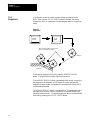
Important User Information
Because of the variety of uses for the products described in this publication,
those responsible for the application and use of this control equipment must
satisfy themselves that all necessary steps have been taken to assure that
each application and use meets all performance and safety requirements,
including any applicable laws, regulations, codes and standards.
The illustrations, charts, sample programs and layout examples shown in
this guide are intended solely for purposes of example. Since there are
many variables and requirements associated with any particular installation,
Allen-Bradley does not assume responsibility or liability (to include
intellectual property liability) for actual use based upon the examples shown
in this publication.
Allen-Bradley publication SGI-1.1, Safety Guidelines for the Application,
Installation, and Maintenance of Solid State Control (available from your
local Allen-Bradley office), describes some important differences between
solid-state equipment and electromechanical devices that should be taken
into consideration when applying products such as those described in this
publication.
Reproduction of the contents of this copyrighted publication, in whole or in
part, without written permission of Allen-Bradley Company, Inc. is prohibited.
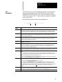
Throughout this manual we make notes to alert you to possible injury to
people or damage to equipment under specific circumstances.
WARNING: Tells readers where people may be hurt if
procedures are not followed properly.
CAUTION: Tells readers where machinery may be damaged or
economic loss can occur if procedures are not followed properly.
Warnings and Cautions:
-
identify a possible trouble spot
tell what causes the trouble
give the result of improper action
tell the reader how to avoid trouble
Important: We recommend that you frequently back up your application
programs on an appropriate storage medium to avoid possible data loss.
PLC is a registered trademark of Allen-Bradley Company, Inc.
Paramacro and PAL are trademarks of Allen-Bradley Company, Inc.
9/Series Mill
Operation and Programming Manual
October 2000
Summary of Changes
New Information
The following is a list of the larger changes made to this manual since its
last printing. Other less significant changes were also made throughout.
Error Message Log
Paramacro Parameters
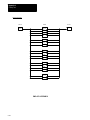
Softkey Tree
Error Messages
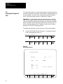
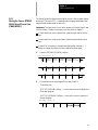
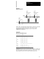
Revision Bars
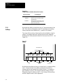
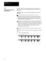
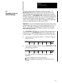
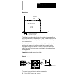
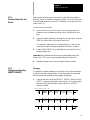
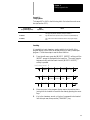
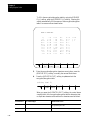
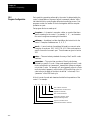
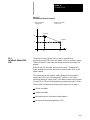
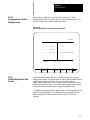
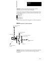
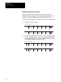
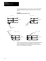
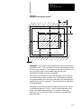
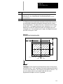
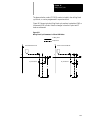
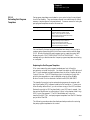
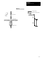
We use revision bars to call your attention to new or revised information.
A revision bar appears as a thick black line on the outside edge of the page
as indicated here.
Chapter
1-2
Table
of Contents
Index
(General)
9/Series
Mill
9/Series
PAL
Reference Manual
Operation and Programming Manual
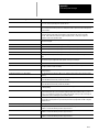
Chapter 1
Using This Manual
1.0 Chapter Overview . . . . . . . . . . . . . . . . . . . . . . . . . . . . . . . . . . . . . . . . . . . . . . . . . . . . . . . . . .
1.1 Audience . . . . . . . . . . . . . . . . . . . . . . . . . . . . . . . . . . . . . . . . . . . . . . . . . . . . . . . . . . . . . . . .
1.2 Manual Design . . . . . . . . . . . . . . . . . . . . . . . . . . . . . . . . . . . . . . . . . . . . . . . . . . . . . . . . . . . .
1.3 Reading this Manual . . . . . . . . . . . . . . . . . . . . . . . . . . . . . . . . . . . . . . . . . . . . . . . . . . . . . . . .
1.4 Terms and Conventions . . . . . . . . . . . . . . . . . . . . . . . . . . . . . . . . . . . . . . . . . . . . . . . . . . . . . .
1.5 Warnings, Cautions, and Important Information . . . . . . . . . . . . . . . . . . . . . . . . . . . . . . . . . . . . . .
1.6 Related Publications . . . . . . . . . . . . . . . . . . . . . . . . . . . . . . . . . . . . . . . . . . . . . . . . . . . . . . . .
1-1
1-1
1-1
1-3
1-4
1-5
1-5
Chapter 2
Basic Control Operation
2.0 Chapter Overview . . . . . . . . . . . . . . . . . . . . . . . . . . . . . . . . . . . . . . . . . . . . . . . . . . . . . . . . . .
2.1 Operator Panel Operations . . . . . . . . . . . . . . . . . . . . . . . . . . . . . . . . . . . . . . . . . . . . . . . . . . . .
2.1.1 Keyboard . . . . . . . . . . . . . . . . . . . . . . . . . . . . . . . . . . . . . . . . . . . . . . . . . . . . . . . . . . . . .
2.1.2 Calculator Function . . . . . . . . . . . . . . . . . . . . . . . . . . . . . . . . . . . . . . . . . . . . . . . . . . . . . .
2.1.3 Softkeys . . . . . . . . . . . . . . . . . . . . . . . . . . . . . . . . . . . . . . . . . . . . . . . . . . . . . . . . . . . . . .
2.1.4 CRT . . . . . . . . . . . . . . . . . . . . . . . . . . . . . . . . . . . . . . . . . . . . . . . . . . . . . . . . . . . . . . . .
2.1.5 Portable Operator Panel . . . . . . . . . . . . . . . . . . . . . . . . . . . . . . . . . . . . . . . . . . . . . . . . . . .
2.2 The MTB Panel . . . . . . . . . . . . . . . . . . . . . . . . . . . . . . . . . . . . . . . . . . . . . . . . . . . . . . . . . . . .
2.3 Software MTB Panel {FRONT PANEL} . . . . . . . . . . . . . . . . . . . . . . . . . . . . . . . . . . . . . . . . . . . .
2.4 Power Procedures . . . . . . . . . . . . . . . . . . . . . . . . . . . . . . . . . . . . . . . . . . . . . . . . . . . . . . . . . .
2.4.1 Turning Power On . . . . . . . . . . . . . . . . . . . . . . . . . . . . . . . . . . . . . . . . . . . . . . . . . . . . . . .
2.4.2 Turning Power OFF . . . . . . . . . . . . . . . . . . . . . . . . . . . . . . . . . . . . . . . . . . . . . . . . . . . . .
2.5 Control Conditions at Power-Up . . . . . . . . . . . . . . . . . . . . . . . . . . . . . . . . . . . . . . . . . . . . . . . .
2.6 Emergency Stop Operations . . . . . . . . . . . . . . . . . . . . . . . . . . . . . . . . . . . . . . . . . . . . . . . . . . .
2.6.1 Emergency Stop Reset . . . . . . . . . . . . . . . . . . . . . . . . . . . . . . . . . . . . . . . . . . . . . . . . . . .
2.7 Access Control . . . . . . . . . . . . . . . . . . . . . . . . . . . . . . . . . . . . . . . . . . . . . . . . . . . . . . . . . . . .
2.7.1 Assigning Access Levels and Passwords . . . . . . . . . . . . . . . . . . . . . . . . . . . . . . . . . . . . . .
2.7.2 Password Protectable Functions . . . . . . . . . . . . . . . . . . . . . . . . . . . . . . . . . . . . . . . . . . . .
2.7.3 Entering Passwords . . . . . . . . . . . . . . . . . . . . . . . . . . . . . . . . . . . . . . . . . . . . . . . . . . . . .
2.8 Changing Operating Modes . . . . . . . . . . . . . . . . . . . . . . . . . . . . . . . . . . . . . . . . . . . . . . . . . . .
2.9 Displaying System and Machine Messages . . . . . . . . . . . . . . . . . . . . . . . . . . . . . . . . . . . . . . . .
2.9.1 Clearing Active Messages {CLEAR ACTIVE} . . . . . . . . . . . . . . . . . . . . . . . . . . . . . . . . . . . .
2.10 The Input Cursor . . . . . . . . . . . . . . . . . . . . . . . . . . . . . . . . . . . . . . . . . . . . . . . . . . . . . . . . . .
2.11 {REFORM MEMORY} . . . . . . . . . . . . . . . . . . . . . . . . . . . . . . . . . . . . . . . . . . . . . . . . . . . . . . .
2.12 Removing an Axis (Axis Detach) . . . . . . . . . . . . . . . . . . . . . . . . . . . . . . . . . . . . . . . . . . . . . . .
2.13 Time Parts Count Display Feature . . . . . . . . . . . . . . . . . . . . . . . . . . . . . . . . . . . . . . . . . . . . . .
2-1
2-1
2-3
2-4
2-8
2-10
2-11
2-12
2-15
2-21
2-21
2-22
2-23
2-24
2-24
2-25
2-26
2-29
2-31
2-33
2-37
2-40
2-41
2-41
2-43
2-43
Chapter 3
Offset Tables and Setup
3.0 Chapter Overview . . . . . . . . . . . . . . . . . . . . . . . . . . . . . . . . . . . . . . . . . . . . . . . . . . . . . . . . . .
3.1 Tool Offset Table {TOOL GEOMET} and {TOOL WEAR} . . . . . . . . . . . . . . . . . . . . . . . . . . . . . . .
3.1.1 Tool Offset Dimensional Parameters . . . . . . . . . . . . . . . . . . . . . . . . . . . . . . . . . . . . . . . . . .
3-1
3-1
3-2
i
TableIndex
of Contents
(General)
9/SeriesManual
Mill
9/Series PAL Reference
Operation and Programming Manual
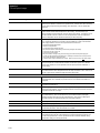
3.1.2 Setting Tool Offset Tables . . . . . . . . . . . . . . . . . . . . . . . . . . . . . . . . . . . . . . . . . . . . . . . . . .
3.1.3 Setting Offset Data Using {MEASURE} . . . . . . . . . . . . . . . . . . . . . . . . . . . . . . . . . . . . . . . .
3.1.4 Tool Offset Range Verification . . . . . . . . . . . . . . . . . . . . . . . . . . . . . . . . . . . . . . . . . . . . . . .
3.2 Changing the Active Tool Offset {ACTIVE OFFSET} . . . . . . . . . . . . . . . . . . . . . . . . . . . . . . . . . .
3.3 Work Coordinate System Offset Tables {WORK CO-ORD} . . . . . . . . . . . . . . . . . . . . . . . . . . . . . .
3.3.1 Setting Work Coordinate System Tables . . . . . . . . . . . . . . . . . . . . . . . . . . . . . . . . . . . . . . .
3.4 Backing Up Offset Tables . . . . . . . . . . . . . . . . . . . . . . . . . . . . . . . . . . . . . . . . . . . . . . . . . . . . .
3.5 Programmable Zone Table . . . . . . . . . . . . . . . . . . . . . . . . . . . . . . . . . . . . . . . . . . . . . . . . . . . .
3.6 Single Digit Feedrate Table . . . . . . . . . . . . . . . . . . . . . . . . . . . . . . . . . . . . . . . . . . . . . . . . . . . .
3-5
3-9
3-10
3-12
3-14
3-15
3-17
3-21
3-23
Chapter 4
Manual/MDI Operation Modes
4.0 Chapter Overview . . . . . . . . . . . . . . . . . . . . . . . . . . . . . . . . . . . . . . . . . . . . . . . . . . . . . . . . . .
4.1 Manual Operating Mode . . . . . . . . . . . . . . . . . . . . . . . . . . . . . . . . . . . . . . . . . . . . . . . . . . . . . .
4.1.1 Jogging an Axis . . . . . . . . . . . . . . . . . . . . . . . . . . . . . . . . . . . . . . . . . . . . . . . . . . . . . . . .
4.1.2 Continuous Jog . . . . . . . . . . . . . . . . . . . . . . . . . . . . . . . . . . . . . . . . . . . . . . . . . . . . . . . . .
4.1.3 Incremental Jog . . . . . . . . . . . . . . . . . . . . . . . . . . . . . . . . . . . . . . . . . . . . . . . . . . . . . . . .
4.1.4 HPG Jog . . . . . . . . . . . . . . . . . . . . . . . . . . . . . . . . . . . . . . . . . . . . . . . . . . . . . . . . . . . . .
4.1.5 Arbitrary Angle Jog . . . . . . . . . . . . . . . . . . . . . . . . . . . . . . . . . . . . . . . . . . . . . . . . . . . . . .
4.1.6 Jog Offset . . . . . . . . . . . . . . . . . . . . . . . . . . . . . . . . . . . . . . . . . . . . . . . . . . . . . . . . . . . . .
4.1.7 Resetting Overtravels . . . . . . . . . . . . . . . . . . . . . . . . . . . . . . . . . . . . . . . . . . . . . . . . . . . . .
4.2 Mechanical Handle Feed (Servo Off) . . . . . . . . . . . . . . . . . . . . . . . . . . . . . . . . . . . . . . . . . . . . .
4.3 Removing an Axis (Axis Detach) . . . . . . . . . . . . . . . . . . . . . . . . . . . . . . . . . . . . . . . . . . . . . . . .
4.4 Manual Machine Homing . . . . . . . . . . . . . . . . . . . . . . . . . . . . . . . . . . . . . . . . . . . . . . . . . . . . .
4.5 MDI Mode . . . . . . . . . . . . . . . . . . . . . . . . . . . . . . . . . . . . . . . . . . . . . . . . . . . . . . . . . . . . . . . .
4.5.1 MDI Basic Operation . . . . . . . . . . . . . . . . . . . . . . . . . . . . . . . . . . . . . . . . . . . . . . . . . . . . .
4-1
4-1
4-2
4-3
4-3
4-4
4-5
4-6
4-6
4-8
4-8
4-8
4-11
4-12
Chapter 5
Editing Programs Online
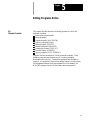
5.0 Chapter Overview . . . . . . . . . . . . . . . . . . . . . . . . . . . . . . . . . . . . . . . . . . . . . . . . . . . . . . . . . .
5.1 Selecting the Program To Edit . . . . . . . . . . . . . . . . . . . . . . . . . . . . . . . . . . . . . . . . . . . . . . . . . .
5.2 Editing Programs at the Control (Online) . . . . . . . . . . . . . . . . . . . . . . . . . . . . . . . . . . . . . . . . . .
5.2.1 Moving the Cursor {STRING SEARCH} and Cursor Size {CHAR/WORD} . . . . . . . . . . . . . . . .
5.2.2 Entering Characters and Blocks . . . . . . . . . . . . . . . . . . . . . . . . . . . . . . . . . . . . . . . . . . . . .
5.2.3 Changing and Inserting {MODIFY INSERT} . . . . . . . . . . . . . . . . . . . . . . . . . . . . . . . . . . . . .
5.2.4 Erasing Characters and Blocks . . . . . . . . . . . . . . . . . . . . . . . . . . . . . . . . . . . . . . . . . . . . .
5.2.5 Sequence Numbers {RENUM PRGRAM} . . . . . . . . . . . . . . . . . . . . . . . . . . . . . . . . . . . . . . .
5.2.6 Merging Part Programs {MERGE PRGRAM} . . . . . . . . . . . . . . . . . . . . . . . . . . . . . . . . . . . .
5.2.7 Exiting Edit Mode {EXIT EDITOR} . . . . . . . . . . . . . . . . . . . . . . . . . . . . . . . . . . . . . . . . . . . .
5.3 Programming
Aids {QUICK VIEW} . . . . . . . . . . . . . . . . . . . . . . . . . . . . . . . . . . . . . . . . . . . .
5.3.1 Selecting a QuickView Plane . . . . . . . . . . . . . . . . . . . . . . . . . . . . . . . . . . . . . . . . . . . . . . .
5.3.2 Using {QPATH+ PROMPT} Sample Patterns . . . . . . . . . . . . . . . . . . . . . . . . . . . . . . . . . . . .
5.3.3 G--code Format Prompting {GCODE PROMPT} . . . . . . . . . . . . . . . . . . . . . . . . . . . . . . . . . .
5.3.4 Mill Cycle Format Prompting . . . . . . . . . . . . . . . . . . . . . . . . . . . . . . . . . . . . . . . . . . . . . . .
ii
5-1
5-2
5-3
5-5
5-7
5-7
5-11
5-13
5-15
5-16
5-17
5-19
5-20
5-24
5-26
Table
of Contents
Index
(General)
9/Series
Mill
9/Series
PAL
Reference Manual
Operation and Programming Manual
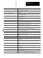
5.4 Digitizing a Program (Teach) . . . . . . . . . . . . . . . . . . . . . . . . . . . . . . . . . . . . . . . . . . . . . . . . . . .
5.4.1 Linear Digitizing . . . . . . . . . . . . . . . . . . . . . . . . . . . . . . . . . . . . . . . . . . . . . . . . . . . . . . . . .
5.4.2 Digitizing an Arc (3 Points) . . . . . . . . . . . . . . . . . . . . . . . . . . . . . . . . . . . . . . . . . . . . . . . . .
5.4.3 Digitizing an Arc Tangent at End Points . . . . . . . . . . . . . . . . . . . . . . . . . . . . . . . . . . . . . . . .
5.5 Deleting Program {DELETE PRGRAM} . . . . . . . . . . . . . . . . . . . . . . . . . . . . . . . . . . . . . . . . . .
5.6 Renaming Programs {RENAME PRGRAM} . . . . . . . . . . . . . . . . . . . . . . . . . . . . . . . . . . . . . . . .
5.7 Displaying a Program {DISPLY PRGRAM} . . . . . . . . . . . . . . . . . . . . . . . . . . . . . . . . . . . . . . . .
5.8 Comment Display {PRGRAM COMENT} . . . . . . . . . . . . . . . . . . . . . . . . . . . . . . . . . . . . . . . . . .
5.9 Copying Programs {COPY PRGRAM} . . . . . . . . . . . . . . . . . . . . . . . . . . . . . . . . . . . . . . . . . . . .
5.10 Selecting the Protectable Part Program Directory . . . . . . . . . . . . . . . . . . . . . . . . . . . . . . . . . . .
5.10.1 Protected Program Encryption and Decryption . . . . . . . . . . . . . . . . . . . . . . . . . . . . . . . . . .
5.10.2 Storing Encryption/Decryption Table to Backup Memory . . . . . . . . . . . . . . . . . . . . . . . . . .
5-28
5-30
5-32
5-34
5-37
5-38
5-39
5-40
5-41
5-43
5-46
5-49
Chapter 6
Editing Part Programs Offline (ODS)
6.0 Chapter Overview . . . . . . . . . . . . . . . . . . . . . . . . . . . . . . . . . . . . . . . . . . . . . . . . . . . . . . . . . .
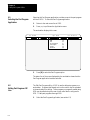
6.1 Selecting the Part Program Application . . . . . . . . . . . . . . . . . . . . . . . . . . . . . . . . . . . . . . . . . . .
6.2 Editing Part Programs Off Line . . . . . . . . . . . . . . . . . . . . . . . . . . . . . . . . . . . . . . . . . . . . . . . . .
6.3 Interfacing the Workstation with the Control . . . . . . . . . . . . . . . . . . . . . . . . . . . . . . . . . . . . . . . .
6.4 Downloading Part Programs from ODS . . . . . . . . . . . . . . . . . . . . . . . . . . . . . . . . . . . . . . . . . . .
6.5 Upload Part Programs to ODS . . . . . . . . . . . . . . . . . . . . . . . . . . . . . . . . . . . . . . . . . . . . . . . . .
6-1
6-2
6-2
6-5
6-5
6-12
Chapter 7
Running a Program
7.0 Chapter Overview . . . . . . . . . . . . . . . . . . . . . . . . . . . . . . . . . . . . . . . . . . . . . . . . . . . . . . . . . .
7.1 Selecting Special Running Conditions . . . . . . . . . . . . . . . . . . . . . . . . . . . . . . . . . . . . . . . . . . . .
7.1.1 Block Delete . . . . . . . . . . . . . . . . . . . . . . . . . . . . . . . . . . . . . . . . . . . . . . . . . . . . . . . . . . .
7.1.2 Miscellaneous Function Lock . . . . . . . . . . . . . . . . . . . . . . . . . . . . . . . . . . . . . . . . . . . . . .
7.1.3 Sequence Stop {SEQ STOP} . . . . . . . . . . . . . . . . . . . . . . . . . . . . . . . . . . . . . . . . . . . . . . .
7.1.4 Single Block . . . . . . . . . . . . . . . . . . . . . . . . . . . . . . . . . . . . . . . . . . . . . . . . . . . . . . . . . .
7.2 Selecting a Part Program Input Device . . . . . . . . . . . . . . . . . . . . . . . . . . . . . . . . . . . . . . . . . . . .
7.3 Selecting a Program . . . . . . . . . . . . . . . . . . . . . . . . . . . . . . . . . . . . . . . . . . . . . . . . . . . . . . . . .
7.4 Deselecting a Part Program . . . . . . . . . . . . . . . . . . . . . . . . . . . . . . . . . . . . . . . . . . . . . . . . . . .
7.5 Program Search {SEARCH} . . . . . . . . . . . . . . . . . . . . . . . . . . . . . . . . . . . . . . . . . . . . . . . . . . .
7.6 Search With Recall {MID ST PRGRAM} . . . . . . . . . . . . . . . . . . . . . . . . . . . . . . . . . . . . . . . . . .
7.7 Basic Program Execution . . . . . . . . . . . . . . . . . . . . . . . . . . . . . . . . . . . . . . . . . . . . . . . . . . . . .
7.7.1 {QUICK CHECK} . . . . . . . . . . . . . . . . . . . . . . . . . . . . . . . . . . . . . . . . . . . . . . . . . . . . . . . .
7.7.2 Axis Inhibit Mode . . . . . . . . . . . . . . . . . . . . . . . . . . . . . . . . . . . . . . . . . . . . . . . . . . . . . . .
7.7.3 Dry Run Mode . . . . . . . . . . . . . . . . . . . . . . . . . . . . . . . . . . . . . . . . . . . . . . . . . . . . . . . . .
7.7.4 Part Production/Automatic Mode . . . . . . . . . . . . . . . . . . . . . . . . . . . . . . . . . . . . . . . . . . . .
7.8 Interrupted Program Recover {RESTRT PRGRAM} . . . . . . . . . . . . . . . . . . . . . . . . . . . . . . . . . .
7.9 Jog Retract . . . . . . . . . . . . . . . . . . . . . . . . . . . . . . . . . . . . . . . . . . . . . . . . . . . . . . . . . . . . . . .
7.10 Block Retrace . . . . . . . . . . . . . . . . . . . . . . . . . . . . . . . . . . . . . . . . . . . . . . . . . . . . . . . . . . . .
7-1
7-1
7-1
7-2
7-2
7-4
7-5
7-6
7-9
7-10
7-13
7-17
7-19
7-20
7-21
7-23
7-25
7-28
7-31
iii
TableIndex
of Contents
(General)
9/SeriesManual
Mill
9/Series PAL Reference
Operation and Programming Manual
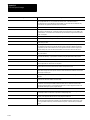
Chapter 8
Display and Graphics
8.0 Chapter Overview . . . . . . . . . . . . . . . . . . . . . . . . . . . . . . . . . . . . . . . . . . . . . . . . . . . . . . . . . .
8.1 Selection of Axis Position Data Display . . . . . . . . . . . . . . . . . . . . . . . . . . . . . . . . . . . . . . . . . . .
8.2 PAL Display Page . . . . . . . . . . . . . . . . . . . . . . . . . . . . . . . . . . . . . . . . . . . . . . . . . . . . . . . . . .
8.3 Changing Languages . . . . . . . . . . . . . . . . . . . . . . . . . . . . . . . . . . . . . . . . . . . . . . . . . . . . . . . .
8.4 Graphics . . . . . . . . . . . . . . . . . . . . . . . . . . . . . . . . . . . . . . . . . . . . . . . . . . . . . . . . . . . . . . . . .
8.4.1 Selecting the Program for Graphics . . . . . . . . . . . . . . . . . . . . . . . . . . . . . . . . . . . . . . . . . .
8.4.2 Running Graphics . . . . . . . . . . . . . . . . . . . . . . . . . . . . . . . . . . . . . . . . . . . . . . . . . . . . . .
8.4.3 Disabling Graphics . . . . . . . . . . . . . . . . . . . . . . . . . . . . . . . . . . . . . . . . . . . . . . . . . . . . . .
8.4.4 Changing Parameters . . . . . . . . . . . . . . . . . . . . . . . . . . . . . . . . . . . . . . . . . . . . . . . . . . . .
8.4.5 Graphics in Single-Block . . . . . . . . . . . . . . . . . . . . . . . . . . . . . . . . . . . . . . . . . . . . . . . . . .
8.4.6 Clearing Graphics Screen . . . . . . . . . . . . . . . . . . . . . . . . . . . . . . . . . . . . . . . . . . . . . . . . .
8.4.7 Displaying Machine Information in Graphics . . . . . . . . . . . . . . . . . . . . . . . . . . . . . . . . . . . .
8.4.8 Zooming Graphics . . . . . . . . . . . . . . . . . . . . . . . . . . . . . . . . . . . . . . . . . . . . . . . . . . . . . .
8.6 Power Turn-on Screen . . . . . . . . . . . . . . . . . . . . . . . . . . . . . . . . . . . . . . . . . . . . . . . . . . . . . . .
8.7 Screen Saver . . . . . . . . . . . . . . . . . . . . . . . . . . . . . . . . . . . . . . . . . . . . . . . . . . . . . . . . . . . . .
8-1
8-1
8-22
8-23
8-24
8-24
8-25
8-27
8-27
8-33
8-33
8-33
8-33
8-37
8-39
Chapter 9
Communications
9.0 Chapter Overview . . . . . . . . . . . . . . . . . . . . . . . . . . . . . . . . . . . . . . . . . . . . . . . . . . . . . . . . . .
9.1 Setting Communications . . . . . . . . . . . . . . . . . . . . . . . . . . . . . . . . . . . . . . . . . . . . . . . . . . . . . .
9.1.1 Setting Communication Port Parameter Values . . . . . . . . . . . . . . . . . . . . . . . . . . . . . . . . . . .
9.1.2 Communication Port Parameters . . . . . . . . . . . . . . . . . . . . . . . . . . . . . . . . . . . . . . . . . . . . .
9.2 Inputting Part Programs from a Tape Reader . . . . . . . . . . . . . . . . . . . . . . . . . . . . . . . . . . . . . . .
9.3 Outputting Part Programs to a Tape Punch . . . . . . . . . . . . . . . . . . . . . . . . . . . . . . . . . . . . . . . . .
9.4 Verifying Part Programs Against Source Programs . . . . . . . . . . . . . . . . . . . . . . . . . . . . . . . . . . .
9.5 Error Conditions (Inputting and Outputting Part Programs) . . . . . . . . . . . . . . . . . . . . . . . . . . . . . .
9-1
9-1
9-1
9-3
9-9
9-13
9-17
9-18
Chapter 10
Introduction to Programming
10.0 Chapter Overview . . . . . . . . . . . . . . . . . . . . . . . . . . . . . . . . . . . . . . . . . . . . . . . . . . . . . . . . .
10.1 Tape Format . . . . . . . . . . . . . . . . . . . . . . . . . . . . . . . . . . . . . . . . . . . . . . . . . . . . . . . . . . . . .
10.2 Program Configuration . . . . . . . . . . . . . . . . . . . . . . . . . . . . . . . . . . . . . . . . . . . . . . . . . . . . . .
10.2.1 Program Names . . . . . . . . . . . . . . . . . . . . . . . . . . . . . . . . . . . . . . . . . . . . . . . . . . . . . . .
10.2.2 Sequence Numbers . . . . . . . . . . . . . . . . . . . . . . . . . . . . . . . . . . . . . . . . . . . . . . . . . . . .
10.2.3 Comment Blocks . . . . . . . . . . . . . . . . . . . . . . . . . . . . . . . . . . . . . . . . . . . . . . . . . . . . . . .
10.2.4 Block Delete and Multi Level Delete . . . . . . . . . . . . . . . . . . . . . . . . . . . . . . . . . . . . . . . . .
10.2.5 End of Block Statement . . . . . . . . . . . . . . . . . . . . . . . . . . . . . . . . . . . . . . . . . . . . . . . . . .
10.3 Using Subprograms . . . . . . . . . . . . . . . . . . . . . . . . . . . . . . . . . . . . . . . . . . . . . . . . . . . . . . . .
10.3.1 Subprogram Call (M98) . . . . . . . . . . . . . . . . . . . . . . . . . . . . . . . . . . . . . . . . . . . . . . . . . .
10.3.2 Main and Subprogram Return (M99) . . . . . . . . . . . . . . . . . . . . . . . . . . . . . . . . . . . . . . . . .
10.3.3 Subprogram Nesting . . . . . . . . . . . . . . . . . . . . . . . . . . . . . . . . . . . . . . . . . . . . . . . . . . . .
10.4 Word Formats and Functions . . . . . . . . . . . . . . . . . . . . . . . . . . . . . . . . . . . . . . . . . . . . . . . . .
iv
10-1
10-1
10-6
10-8
10-9
10-10
10-10
10-11
10-12
10-13
10-14
10-16
10-17
Table
of Contents
Index
(General)
9/Series
Mill
9/Series
PAL
Reference Manual
Operation and Programming Manual
10.4.1 Minimum and Maximum Axis Motion (Programming Resolution) . . . . . . . . . . . . . . . . . . . . .
10.5 Word Descriptions . . . . . . . . . . . . . . . . . . . . . . . . . . . . . . . . . . . . . . . . . . . . . . . . . . . . . . . . .
10.5.1 A_ L_ ,R_ ,C_ (Quick Plus and Radius-Chamfer Words) . . . . . . . . . . . . . . . . . . . . . . . . . .
10.5.2 Axis Names . . . . . . . . . . . . . . . . . . . . . . . . . . . . . . . . . . . . . . . . . . . . . . . . . . . . . . . . .
10.5.3 D --and H--Words (Tool Offsets) . . . . . . . . . . . . . . . . . . . . . . . . . . . . . . . . . . . . . . . . . . . .
10.5.4 F--words (Feedrate) . . . . . . . . . . . . . . . . . . . . . . . . . . . . . . . . . . . . . . . . . . . . . . . . . . . .
10.5.5 G--codes (Preparatory Functions) . . . . . . . . . . . . . . . . . . . . . . . . . . . . . . . . . . . . . . . . . .
10.5.6 I ,J, and K Integrand Words . . . . . . . . . . . . . . . . . . . . . . . . . . . . . . . . . . . . . . . . . . . . .
10.5.7 M --codes(Miscellaneous Functions) . . . . . . . . . . . . . . . . . . . . . . . . . . . . . . . . . . . . . . . .
10.5.7.1 Auxiliary Miscellaneous Function (B--word) . . . . . . . . . . . . . . . . . . . . . . . . . . . . . . . . . .
10.5.8 N--words (Sequence Numbers) . . . . . . . . . . . . . . . . . . . . . . . . . . . . . . . . . . . . . . . . . . . .
10.5.9 O--words (Program Names) . . . . . . . . . . . . . . . . . . . . . . . . . . . . . . . . . . . . . . . . . . . . . .
10.5.10 P ,L (Main Program Jumps and Subprogram Calls) . . . . . . . . . . . . . . . . . . . . . . . . . . . . .
10.5.11 S--word (Spindle Speed) . . . . . . . . . . . . . . . . . . . . . . . . . . . . . . . . . . . . . . . . . . . . . . . .
10.5.12 T--words (Tool Selection) . . . . . . . . . . . . . . . . . . . . . . . . . . . . . . . . . . . . . . . . . . . . . . . .
10-21
10-22
10-22
10-22
10-22
10-23
10-24
10-30
10-30
10-37
10-37
10-37
10-37
10-38
10-40
Chapter 11
Coordinate Systems Offsets
11.0 Chapter Overview . . . . . . . . . . . . . . . . . . . . . . . . . . . . . . . . . . . . . . . . . . . . . . . . . . . . . . . . .
11.1 Machine Coordinate System (Absolute) . . . . . . . . . . . . . . . . . . . . . . . . . . . . . . . . . . . . . . . . . .
11.1.1 Motion in the Machine Coordinate System (G53) . . . . . . . . . . . . . . . . . . . . . . . . . . . . . . . . .
11.2 Preset Work Coordinate Systems (G54-59.3) . . . . . . . . . . . . . . . . . . . . . . . . . . . . . . . . . . . . . .
11.2.1 Altering Work Coordinate Systems (G10L2) . . . . . . . . . . . . . . . . . . . . . . . . . . . . . . . . . . . .
11.3 Work Coordinate System External Offset . . . . . . . . . . . . . . . . . . . . . . . . . . . . . . . . . . . . . . . . .
11.3.1 Altering External Offset (G10L2) . . . . . . . . . . . . . . . . . . . . . . . . . . . . . . . . . . . . . . . . . . . .
11.4 Offsetting the Work Coordinate Systems . . . . . . . . . . . . . . . . . . . . . . . . . . . . . . . . . . . . . . . . . .
11.4.1 Coordinate Offset Using Tool Position (G92) . . . . . . . . . . . . . . . . . . . . . . . . . . . . . . . . . . . .
11.4.2 Offsetting Coordinate Zero Points (G52) . . . . . . . . . . . . . . . . . . . . . . . . . . . . . . . . . . . . . . .
11.4.3 {SET ZERO} Offset . . . . . . . . . . . . . . . . . . . . . . . . . . . . . . . . . . . . . . . . . . . . . . . . . . . . .
11.4.4 Jogging an Offset . . . . . . . . . . . . . . . . . . . . . . . . . . . . . . . . . . . . . . . . . . . . . . . . . . . . . . .
11.4.5 Canceling Coordinate System Offsets (G92.1) . . . . . . . . . . . . . . . . . . . . . . . . . . . . . . . . . .
11.4.6 Canceling Selected Coordinate System Offsets (G92.2) . . . . . . . . . . . . . . . . . . . . . . . . . .
11.5 PAL Offsets . . . . . . . . . . . . . . . . . . . . . . . . . . . . . . . . . . . . . . . . . . . . . . . . . . . . . . . . . . . . . .
11-1
11-1
11-2
11-4
11-7
11-9
11-11
11-13
11-13
11-16
11-18
11-19
11-20
11-21
11-22
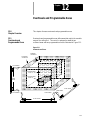
Chapter 12
Overtravels and Programmable Zones
12.0 Chapter Overview . . . . . . . . . . . . . . . . . . . . . . . . . . . . . . . . . . . . . . . . . . . . . . . . . . . . . . . . .
12.1 Hardware Overtravels . . . . . . . . . . . . . . . . . . . . . . . . . . . . . . . . . . . . . . . . . . . . . . . . . . . . . .
12.2 Software Overtravels . . . . . . . . . . . . . . . . . . . . . . . . . . . . . . . . . . . . . . . . . . . . . . . . . . . . . . .
12.3 Programmable Zone 2 (G22, G23) . . . . . . . . . . . . . . . . . . . . . . . . . . . . . . . . . . . . . . . . . . . . . .
12.4 Programmable Zone 3 (G22.1, G23.1) . . . . . . . . . . . . . . . . . . . . . . . . . . . . . . . . . . . . . . . . . . .
12.5 Resetting Overtravels . . . . . . . . . . . . . . . . . . . . . . . . . . . . . . . . . . . . . . . . . . . . . . . . . . . . . . .
12-1
12-2
12-3
12-5
12-7
12-13
v
TableIndex
of Contents
(General)
9/SeriesManual
Mill
9/Series PAL Reference
Operation and Programming Manual
Chapter 13
Coordinate Control
13.0 Chapter Overview . . . . . . . . . . . . . . . . . . . . . . . . . . . . . . . . . . . . . . . . . . . . . . . . . . . . . . . . .
13.1 Rotating the Coordinate Systems . . . . . . . . . . . . . . . . . . . . . . . . . . . . . . . . . . . . . . . . . . . . . . .
13.1.1 Rotating the Current Work Coordinate System (G68, G69) . . . . . . . . . . . . . . . . . . . . . . . . .
13.1.2 External Part Rotation . . . . . . . . . . . . . . . . . . . . . . . . . . . . . . . . . . . . . . . . . . . . . . . . . . .
13.2 Plane Selection (G17, G18, G19) . . . . . . . . . . . . . . . . . . . . . . . . . . . . . . . . . . . . . . . . . . . . . . .
13.3 Absolute/Incremental Modes (G90, G91) . . . . . . . . . . . . . . . . . . . . . . . . . . . . . . . . . . . . . . . . .
13.4 Inch/Metric Modes (G20, G21) . . . . . . . . . . . . . . . . . . . . . . . . . . . . . . . . . . . . . . . . . . . . . . . .
13.5 Scaling . . . . . . . . . . . . . . . . . . . . . . . . . . . . . . . . . . . . . . . . . . . . . . . . . . . . . . . . . . . . . . . . .
13.5.1 Scaling and Axis Position Display Screens . . . . . . . . . . . . . . . . . . . . . . . . . . . . . . . . . . . .
13.5.2 Scaling Magnification Data Screen . . . . . . . . . . . . . . . . . . . . . . . . . . . . . . . . . . . . . . . . . .
13.5.3 Scaling Restrictions . . . . . . . . . . . . . . . . . . . . . . . . . . . . . . . . . . . . . . . . . . . . . . . . . . . .
13-1
13-1
13-2
13-6
13-11
13-12
13-13
13-14
13-17
13-17
13-19
Chapter 14
Axis Motion
14.0 Chapter Overview . . . . . . . . . . . . . . . . . . . . . . . . . . . . . . . . . . . . . . . . . . . . . . . . . . . . . . . . .
14.1 Positioning Axes . . . . . . . . . . . . . . . . . . . . . . . . . . . . . . . . . . . . . . . . . . . . . . . . . . . . . . . . . .
14.1.1 Rapid Positioning Mode (G00) . . . . . . . . . . . . . . . . . . . . . . . . . . . . . . . . . . . . . . . . . . . . .
14.1.2 Linear Interpolation Mode (G01) . . . . . . . . . . . . . . . . . . . . . . . . . . . . . . . . . . . . . . . . . . .
14.1.3 Circular Interpolation Mode (G02, G03) . . . . . . . . . . . . . . . . . . . . . . . . . . . . . . . . . . . . . .
14.1.4 Helical Interpolation Mode (G02, G03) . . . . . . . . . . . . . . . . . . . . . . . . . . . . . . . . . . . . . . .
14.1.5 Positioning Rotary Axes . . . . . . . . . . . . . . . . . . . . . . . . . . . . . . . . . . . . . . . . . . . . . . . . .
14.1.6 Cylindrical Interpolation . . . . . . . . . . . . . . . . . . . . . . . . . . . . . . . . . . . . . . . . . . . . . . . . . .
14.1.7 PAL Axis Mover . . . . . . . . . . . . . . . . . . . . . . . . . . . . . . . . . . . . . . . . . . . . . . . . . . . . . . .
14.2 Polar Coordinate Programming (G15, G16) . . . . . . . . . . . . . . . . . . . . . . . . . . . . . . . . . . . . . . .
14.2.1 Polar Programming Special Cases . . . . . . . . . . . . . . . . . . . . . . . . . . . . . . . . . . . . . . . . .
14.3 Automatic Motion To and From Machine Home . . . . . . . . . . . . . . . . . . . . . . . . . . . . . . . . . . . .
14.3.1 Automatic Machine Homing (G28) . . . . . . . . . . . . . . . . . . . . . . . . . . . . . . . . . . . . . . . . .
14.3.2 Automatic Return to Machine Home (G28) . . . . . . . . . . . . . . . . . . . . . . . . . . . . . . . . . . . .
14.3.3 Automatic Return From Machine Home (G29) . . . . . . . . . . . . . . . . . . . . . . . . . . . . . . . . .
14.3.4 Machine Home Return Check (G27) . . . . . . . . . . . . . . . . . . . . . . . . . . . . . . . . . . . . . . . .
14.3.5 Return to Alternate Home (G30) . . . . . . . . . . . . . . . . . . . . . . . . . . . . . . . . . . . . . . . . . . .
14.4 Dwell (G04) . . . . . . . . . . . . . . . . . . . . . . . . . . . . . . . . . . . . . . . . . . . . . . . . . . . . . . . . . . . . .
14.4.1 Dwell - Seconds . . . . . . . . . . . . . . . . . . . . . . . . . . . . . . . . . . . . . . . . . . . . . . . . . . . . . .
14.4.2 Dwell - Number of Spindle Revolutions . . . . . . . . . . . . . . . . . . . . . . . . . . . . . . . . . . . . . .
14.5 Programmable Mirror Image (G50.1 - G51.5) . . . . . . . . . . . . . . . . . . . . . . . . . . . . . . . . . . . . . .
14.5.1 Manual Mirror Image . . . . . . . . . . . . . . . . . . . . . . . . . . . . . . . . . . . . . . . . . . . . . . . . . . .
14.6 Axis Clamp . . . . . . . . . . . . . . . . . . . . . . . . . . . . . . . . . . . . . . . . . . . . . . . . . . . . . . . . . . . . . .
14.7 Feed to Hard Stop (G24) . . . . . . . . . . . . . . . . . . . . . . . . . . . . . . . . . . . . . . . . . . . . . . . . . . . .
vi
14-1
14-1
14-1
14-3
14-5
14-10
14-12
14-14
14-20
14-21
14-25
14-29
14-29
14-30
14-32
14-33
14-34
14-35
14-36
14-36
14-36
14-38
14-39
14-40
Table
of Contents
Index
(General)
9/Series
Mill
9/Series
PAL
Reference Manual
Operation and Programming Manual
Chapter 15
Using QuickPath Plust
15.0
15.1
15.2
15.3
Chapter Overview . . . . . . . . . . . . . . . . . . . . . . . . . . . . . . . . . . . . . . . . . . . . . . . . . . . . . . . . .
Using QuickPath Plus . . . . . . . . . . . . . . . . . . . . . . . . . . . . . . . . . . . . . . . . . . . . . . . . . . . . . .
Linear QuickPath Plus . . . . . . . . . . . . . . . . . . . . . . . . . . . . . . . . . . . . . . . . . . . . . . . . . . . . . .
Circular QuickPath Plus (G13, G13.1) . . . . . . . . . . . . . . . . . . . . . . . . . . . . . . . . . . . . . . . . . . .
15-1
15-1
15-3
15-7
Chapter 16
Using Chamfers and Corner Radius
16.0 Chapter Overview . . . . . . . . . . . . . . . . . . . . . . . . . . . . . . . . . . . . . . . . . . . . . . . . . . . . . . . . .
16.1 Chamfers and Corner Radius . . . . . . . . . . . . . . . . . . . . . . . . . . . . . . . . . . . . . . . . . . . . . . . . .
16-1
16-1
Chapter 17
Spindles
17.0 Chapter Overview . . . . . . . . . . . . . . . . . . . . . . . . . . . . . . . . . . . . . . . . . . . . . . . . . . . . . . . . .
17.1 Controlling Spindle (G12.1, G12.2, G12.3) . . . . . . . . . . . . . . . . . . . . . . . . . . . . . . . . . . . . . . . .
17.2 Spindle Orientation (M19) . . . . . . . . . . . . . . . . . . . . . . . . . . . . . . . . . . . . . . . . . . . . . . . . . . .
17.3 Spindle Direction (M03, M04, M05) . . . . . . . . . . . . . . . . . . . . . . . . . . . . . . . . . . . . . . . . . . . . .
17.4 Synchronized Spindles . . . . . . . . . . . . . . . . . . . . . . . . . . . . . . . . . . . . . . . . . . . . . . . . . . . . .
17.4.1 Using the Spindle Synchronization Feature . . . . . . . . . . . . . . . . . . . . . . . . . . . . . . . . . . .
17.5 Special Considerations for Spindle Synchronization . . . . . . . . . . . . . . . . . . . . . . . . . . . . . . . . .
17-1
17-1
17-3
17-5
17-6
17-7
17-9
Chapter 18
Programming Feedrates
18.0 Chapter Overview . . . . . . . . . . . . . . . . . . . . . . . . . . . . . . . . . . . . . . . . . . . . . . . . . . . . . . . . .
18.1 Feedrates . . . . . . . . . . . . . . . . . . . . . . . . . . . . . . . . . . . . . . . . . . . . . . . . . . . . . . . . . . . . . . .
18.1.1 Feedrates Applied During Cutter Compensation . . . . . . . . . . . . . . . . . . . . . . . . . . . . . . . .
18.1.2 Inverse Time Feed Mode (G93) . . . . . . . . . . . . . . . . . . . . . . . . . . . . . . . . . . . . . . . . . .
18.1.3 Feed--Per--Minute Mode (G94) . . . . . . . . . . . . . . . . . . . . . . . . . . . . . . . . . . . . . . . . . . .
18.1.4 Feed--Per--Revolution Mode (G95) . . . . . . . . . . . . . . . . . . . . . . . . . . . . . . . . . . . . . . . . .
18.1.5 Rapid Feedrate . . . . . . . . . . . . . . . . . . . . . . . . . . . . . . . . . . . . . . . . . . . . . . . . . . . . . .
18.1.6 Feedrate Overrides . . . . . . . . . . . . . . . . . . . . . . . . . . . . . . . . . . . . . . . . . . . . . . . . . . .
18.1.7 Feedrate Limits (Clamp) . . . . . . . . . . . . . . . . . . . . . . . . . . . . . . . . . . . . . . . . . . . . . . . .
18.2 Feedrates to Control Torque Adaptive Feed (G25) . . . . . . . . . . . . . . . . . . . . . . . . . . . . . . . . . .
18.3 Special AMP Assigned Feedrates . . . . . . . . . . . . . . . . . . . . . . . . . . . . . . . . . . . . . . . . . . . . . .
18.3.1 Single Digit F--words . . . . . . . . . . . . . . . . . . . . . . . . . . . . . . . . . . . . . . . . . . . . . . . . . . .
18.3.2 External Feedrate Switch . . . . . . . . . . . . . . . . . . . . . . . . . . . . . . . . . . . . . . . . . . . . . . .
18.4 Automatic Acceleration/Deceleration (Acc/Dec) . . . . . . . . . . . . . . . . . . . . . . . . . . . . . . . . . . . .
18.4.1 Exponential Acc/Dec . . . . . . . . . . . . . . . . . . . . . . . . . . . . . . . . . . . . . . . . . . . . . . . . . . .
18.4.2 Linear Acc/Dec . . . . . . . . . . . . . . . . . . . . . . . . . . . . . . . . . . . . . . . . . . . . . . . . . . . . . . .
18.4.3 S--Curve Acc/Dec . . . . . . . . . . . . . . . . . . . . . . . . . . . . . . . . . . . . . . . . . . . . . . . . . . . . .
18.4.4 Programmable Acc/Dec . . . . . . . . . . . . . . . . . . . . . . . . . . . . . . . . . . . . . . . . . . . . . . . . .
18.4.5 Precautions on Corner Cutting . . . . . . . . . . . . . . . . . . . . . . . . . . . . . . . . . . . . . . . . . . . .
18.4.6 Spindle Acceleration (Ramp) . . . . . . . . . . . . . . . . . . . . . . . . . . . . . . . . . . . . . . . . . . . . . .
18-1
18-1
18-2
18-4
18-5
18-5
18-6
18-7
18-8
18-9
18-12
18-12
18-13
18-14
18-15
18-16
18-17
18-18
18-20
18-22
vii
TableIndex
of Contents
(General)
9/SeriesManual
Mill
9/Series PAL Reference
Operation and Programming Manual
18.4.7 Short Block Acc/Dec G36, G36.1 . . . . . . . . . . . . . . . . . . . . . . . . . . . . . . . . . . . . . . . . .
18-22
Chapter 19
Dual--- axis Operation
19.0 Chapter Overview . . . . . . . . . . . . . . . . . . . . . . . . . . . . . . . . . . . . . . . . . . . . . . . . . . . . . . . . .
19.1 Dual--axis Operation . . . . . . . . . . . . . . . . . . . . . . . . . . . . . . . . . . . . . . . . . . . . . . . . . . . . . . .
19.1.1 Parking a Dual Axis . . . . . . . . . . . . . . . . . . . . . . . . . . . . . . . . . . . . . . . . . . . . . . . . . . .
19.1.2 Homing a Dual Axis . . . . . . . . . . . . . . . . . . . . . . . . . . . . . . . . . . . . . . . . . . . . . . . . . . .
19.1.3 Programming a Dual Axis . . . . . . . . . . . . . . . . . . . . . . . . . . . . . . . . . . . . . . . . . . . . . . .
19.1.4 Offset Management for a Dual Axis . . . . . . . . . . . . . . . . . . . . . . . . . . . . . . . . . . . . . . .
19-1
19-1
19-3
19-4
19-5
19-7
Chapter 20
Tool Control Functions
20.0 Chapter Overview . . . . . . . . . . . . . . . . . . . . . . . . . . . . . . . . . . . . . . . . . . . . . . . . . . . . . . . . .
20.1 Programming a T--word . . . . . . . . . . . . . . . . . . . . . . . . . . . . . . . . . . . . . . . . . . . . . . . . . . . . .
20.2 Tool Length Offset Function (G43, G44, G49) . . . . . . . . . . . . . . . . . . . . . . . . . . . . . . . . . . . . . .
20.2.1 Activating Tool Length Offsets . . . . . . . . . . . . . . . . . . . . . . . . . . . . . . . . . . . . . . . . . . . .
20.2.2 Tool Length Offset (TLO) Axis Selection (G43.1, G44.1) . . . . . . . . . . . . . . . . . . . . . . . . . . .
20.3 Random Tool . . . . . . . . . . . . . . . . . . . . . . . . . . . . . . . . . . . . . . . . . . . . . . . . . . . . . . . . . . . .
20.4 Programming Alterations of the Offset Tables (G10L10 -- G10L13) . . . . . . . . . . . . . . . . . . . . . . .
20.5 Automatic Tool Life Management . . . . . . . . . . . . . . . . . . . . . . . . . . . . . . . . . . . . . . . . . . . . . .
20.5.1 Tool Directory Data . . . . . . . . . . . . . . . . . . . . . . . . . . . . . . . . . . . . . . . . . . . . . . . . . . . .
20.5.2 Assigning Detailed Tool Data . . . . . . . . . . . . . . . . . . . . . . . . . . . . . . . . . . . . . . . . . . . . .
20.5.3 Programming Data and Backing Up Tool Management Tables (G10L3, G11) . . . . . . . . . . . .
20.5.4 Programming Using Tool Management . . . . . . . . . . . . . . . . . . . . . . . . . . . . . . . . . . . . . .
20-1
20-1
20-3
20-8
20-9
20-11
20-18
20-19
20-20
20-25
20-29
20-33
Chapter 21
Cutter Diameter Compensation (G40, G41, G42)
21.0 Chapter Overview . . . . . . . . . . . . . . . . . . . . . . . . . . . . . . . . . . . . . . . . . . . . . . . . . . . . . . . . .
21.1 Active Cutter Compensation . . . . . . . . . . . . . . . . . . . . . . . . . . . . . . . . . . . . . . . . . . . . . . . . . .
21.2 Cutter Compensation Generated Blocks G39, G39.1 . . . . . . . . . . . . . . . . . . . . . . . . . . . . . . . .
21.3 Cutter Compensation (Type A) . . . . . . . . . . . . . . . . . . . . . . . . . . . . . . . . . . . . . . . . . . . . . . . .
21.3.1 Cutter Compensation Type A Entry Moves . . . . . . . . . . . . . . . . . . . . . . . . . . . . . . . . . . .
21.3.2 Cutter Compensation Type A Exit Moves . . . . . . . . . . . . . . . . . . . . . . . . . . . . . . . . . . . .
21.4 Cutter Compensation (Type B) . . . . . . . . . . . . . . . . . . . . . . . . . . . . . . . . . . . . . . . . . . . . . . .
21.4.1 Cutter Compensation Type B Entry Moves . . . . . . . . . . . . . . . . . . . . . . . . . . . . . . . . . . .
21.4.2 Cutter Compensation Type B Exit Moves . . . . . . . . . . . . . . . . . . . . . . . . . . . . . . . . . . .
21.5 Tool Path During Cutter Compensation . . . . . . . . . . . . . . . . . . . . . . . . . . . . . . . . . . . . . . . . . .
21.6 Cutter Compensation Special Cases . . . . . . . . . . . . . . . . . . . . . . . . . . . . . . . . . . . . . . . . . . . .
21.6.1 Changing Cutter Compensation Direction . . . . . . . . . . . . . . . . . . . . . . . . . . . . . . . . . . . .
21.6.2 Too Many Non-Motion Blocks . . . . . . . . . . . . . . . . . . . . . . . . . . . . . . . . . . . . . . . . . . . .
21.6.3 Corner Movement After Generated Blocks . . . . . . . . . . . . . . . . . . . . . . . . . . . . . . . . . . .
21.6.4 Changing Cutter Radius During Compensation . . . . . . . . . . . . . . . . . . . . . . . . . . . . . . . .
21.6.5 MDI or Manual Motion During Cutter Compensation . . . . . . . . . . . . . . . . . . . . . . . . . . . . .
viii
21-1
21-3
21-7
21-10
21-10
21-14
21-20
21-20
21-24
21-30
21-35
21-35
21-39
21-41
21-43
21-46
Table
of Contents
Index
(General)
9/Series
Mill
9/Series
PAL
Reference Manual
Operation and Programming Manual
21.6.6 Moving To/From Machine Home . . . . . . . . . . . . . . . . . . . . . . . . . . . . . . . . . . . . . . . . . .
21.6.7 Changing or Offsetting Work Coordinate System . . . . . . . . . . . . . . . . . . . . . . . . . . . . . . .
21.6.8 Block Look-Ahead . . . . . . . . . . . . . . . . . . . . . . . . . . . . . . . . . . . . . . . . . . . . . . . . . . . .
21.7 Error Detection for Cutter Compensation . . . . . . . . . . . . . . . . . . . . . . . . . . . . . . . . . . . . . . . . .
21-48
21-49
21-50
21-51
Chapter 22
Using Pocket Milling Cycles
22.0 Chapter Overview . . . . . . . . . . . . . . . . . . . . . . . . . . . . . . . . . . . . . . . . . . . . . . . . . . . . . . . . .
22.1 Pocket Milling Roughing Cycle (G88.1) . . . . . . . . . . . . . . . . . . . . . . . . . . . . . . . . . . . . . . . . . .
22.1.1 Rectangular Pocket Roughing Using G88.1 . . . . . . . . . . . . . . . . . . . . . . . . . . . . . . . . .
22.1.2 Rectangular Pocket Enlarging Using G88.1 . . . . . . . . . . . . . . . . . . . . . . . . . . . . . . . . . . .
22.1.3 Slot Roughing Using G88.1 . . . . . . . . . . . . . . . . . . . . . . . . . . . . . . . . . . . . . . . . . . . . . .
22.1.4 Circular Pocket Roughing Using G88.1 . . . . . . . . . . . . . . . . . . . . . . . . . . . . . . . . . . . . . .
22.1.5 Circular Pocket Enlarging Using G88.1 . . . . . . . . . . . . . . . . . . . . . . . . . . . . . . . . . . . . . .
22.2 Pocket Milling Finishing Cycle (G88.2) . . . . . . . . . . . . . . . . . . . . . . . . . . . . . . . . . . . . . . . . . .
22.2.1 Rectangular Pocket Finishing Using G88.2 . . . . . . . . . . . . . . . . . . . . . . . . . . . . . . . . . . .
22.2.2 Circular Pocket Finishing Using G88.2 . . . . . . . . . . . . . . . . . . . . . . . . . . . . . . . . . . . . . .
22.2.3 Slot Finishing Using G88.2 . . . . . . . . . . . . . . . . . . . . . . . . . . . . . . . . . . . . . . . . . . . . . .
22-1
22-1
22-2
22-5
22-8
22-10
22-13
22-15
22-16
22-19
22-20
Chapter 23
Using Post Milling Cycles
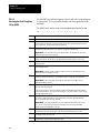
23.0 Chapter Overview . . . . . . . . . . . . . . . . . . . . . . . . . . . . . . . . . . . . . . . . . . . . . . . . . . . . . . . . .
23.1 Post Milling Roughing Cycle (G88.3) . . . . . . . . . . . . . . . . . . . . . . . . . . . . . . . . . . . . . . . . . . . .
23.1.1 Rectangular Post Roughing Using G88.3 . . . . . . . . . . . . . . . . . . . . . . . . . . . . . . . . . . . . .
23.1.2 Circular Post Roughing Using G88.3 . . . . . . . . . . . . . . . . . . . . . . . . . . . . . . . . . . . . . . .
23.2 Post Milling Finishing Cycle (G88.4) . . . . . . . . . . . . . . . . . . . . . . . . . . . . . . . . . . . . . . . . . . . .
23.2.1 Rectangular Post Finishing Using G88.4 . . . . . . . . . . . . . . . . . . . . . . . . . . . . . . . . . . . . .
23.2.2 Circular Post Finishing Using G88.4 . . . . . . . . . . . . . . . . . . . . . . . . . . . . . . . . . . . . . . .
23-1
23-1
23-2
23-5
23-7
23-8
23-11
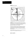
Chapter 24
Using Hemisphere Milling Cycles
24.0 Chapter Overview . . . . . . . . . . . . . . . . . . . . . . . . . . . . . . . . . . . . . . . . . . . . . . . . . . . . . . . . .
24.1 Hemisphere Milling Roughing Cycle (G88.5) . . . . . . . . . . . . . . . . . . . . . . . . . . . . . . . . . . . . . .
24.1.1 Concave Hemisphere Roughing Using G88.5 . . . . . . . . . . . . . . . . . . . . . . . . . . . . . . . . .
24.1.2 Convex Hemisphere Roughing Using G88.5 . . . . . . . . . . . . . . . . . . . . . . . . . . . . . . . . . .
24.2 Hemisphere Milling Finishing Cycle (G88.6) . . . . . . . . . . . . . . . . . . . . . . . . . . . . . . . . . . . . . . .
24.2.1 Concave Hemisphere Finishing Using G88.6 . . . . . . . . . . . . . . . . . . . . . . . . . . . . . . . . .
24.2.2 Convex Hemisphere Finishing Using G88.6 . . . . . . . . . . . . . . . . . . . . . . . . . . . . . . . . . .
24-1
24-1
24-2
24-5
24-7
24-8
24-10
Chapter 25
Irregular Pocket Milling Cycles
25.0 Chapter Overview . . . . . . . . . . . . . . . . . . . . . . . . . . . . . . . . . . . . . . . . . . . . . . . . . . . . . . . . .
25.1 Irregular Pocket Milling . . . . . . . . . . . . . . . . . . . . . . . . . . . . . . . . . . . . . . . . . . . . . . . . . . . . .
25.1.1 Irregular Pocket Roughing (G89.1) . . . . . . . . . . . . . . . . . . . . . . . . . . . . . . . . . . . . . . . . .
25-1
25-1
25-2
ix
TableIndex
of Contents
(General)
9/SeriesManual
Mill
9/Series PAL Reference
Operation and Programming Manual
25.1.2 Irregular Pocket Finishing (G89.2) . . . . . . . . . . . . . . . . . . . . . . . . . . . . . . . . . . . . . . . . . .
25-10
Chapter 26
Milling Fixed Cycles
26.0 Chapter Overview . . . . . . . . . . . . . . . . . . . . . . . . . . . . . . . . . . . . . . . . . . . . . . . . . . . . . . . . .
26.1 Milling Fixed Cycles . . . . . . . . . . . . . . . . . . . . . . . . . . . . . . . . . . . . . . . . . . . . . . . . . . . . . . . .
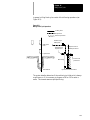
26.2 Positioning and Hole Machining Axes . . . . . . . . . . . . . . . . . . . . . . . . . . . . . . . . . . . . . . . . . . .
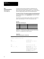
26.3 Parameters . . . . . . . . . . . . . . . . . . . . . . . . . . . . . . . . . . . . . . . . . . . . . . . . . . . . . . . . . . . . .
26.4 Milling Fixed Cycle Operations . . . . . . . . . . . . . . . . . . . . . . . . . . . . . . . . . . . . . . . . . . . . . . . .
(G73): Deep Hole Peck Drilling Cycle with Dwell . . . . . . . . . . . . . . . . . . . . . . . . . . . . . . . . . . . .
(G74): Left-Hand Tapping Cycle . . . . . . . . . . . . . . . . . . . . . . . . . . . . . . . . . . . . . . . . . . . . . . . .
(G74.1): Left-Hand Solid-Tapping Cycle . . . . . . . . . . . . . . . . . . . . . . . . . . . . . . . . . . . . . . . . . . .
(G76): Boring Cycle, Spindle Shift . . . . . . . . . . . . . . . . . . . . . . . . . . . . . . . . . . . . . . . . . . . . .
(G80): Cancel or End Fixed Cycles . . . . . . . . . . . . . . . . . . . . . . . . . . . . . . . . . . . . . . . . . . . .
(G81): Drilling Cycle, No Dwell/Rapid Out . . . . . . . . . . . . . . . . . . . . . . . . . . . . . . . . . . . . . . . .
(G82): Drill Cycle, Dwell/Rapid Out . . . . . . . . . . . . . . . . . . . . . . . . . . . . . . . . . . . . . . . . . . . .
(G83): Deep Hole Drilling Cycle . . . . . . . . . . . . . . . . . . . . . . . . . . . . . . . . . . . . . . . . . . . . . . .
(G84): Right-Hand Tapping Cycle . . . . . . . . . . . . . . . . . . . . . . . . . . . . . . . . . . . . . . . . . . . . .
(G84.1): Right-Hand Solid-Tapping Cycle . . . . . . . . . . . . . . . . . . . . . . . . . . . . . . . . . . . . . . . . .
(G85): Boring Cycle, No Dwell/Feed Out . . . . . . . . . . . . . . . . . . . . . . . . . . . . . . . . . . . . . . . .
(G86): Boring Cycle, Spindle Stop/Rapid Out . . . . . . . . . . . . . . . . . . . . . . . . . . . . . . . . . . . . .
(G87): Back Boring Cycle . . . . . . . . . . . . . . . . . . . . . . . . . . . . . . . . . . . . . . . . . . . . . . . . . . .
(G88): Boring Cycle, Spindle Stop/Manual Out . . . . . . . . . . . . . . . . . . . . . . . . . . . . . . . . . . . .
(G89): Boring Cycle, Dwell/Feed Out . . . . . . . . . . . . . . . . . . . . . . . . . . . . . . . . . . . . . . . . . . .
26.5 Altering Milling Fixed Cycle Operating Parameters . . . . . . . . . . . . . . . . . . . . . . . . . . . . . . . . . .
26.6 Examples of Drilling Cycles . . . . . . . . . . . . . . . . . . . . . . . . . . . . . . . . . . . . . . . . . . . . . . . . . .
26-1
26-2
26-4
26-7
26-8
26-9
26-10
26-12
26-15
26-18
26-18
26-20
26-21
26-23
26-25
26-28
26-30
26-32
26-34
26-36
26-38
26-40
Chapter 27
Skip, Gauge, and Probing Cycles
27.1 Chapter Overview . . . . . . . . . . . . . . . . . . . . . . . . . . . . . . . . . . . . . . . . . . . . . . . . . . . . . . . . .
27.2 External Skip, Gauge, and Probe Functions . . . . . . . . . . . . . . . . . . . . . . . . . . . . . . . . . . . . . . .
27.2 External Skip Functions (G31 codes) . . . . . . . . . . . . . . . . . . . . . . . . . . . . . . . . . . . . . . . . . .
27.3 Tool Gauging External Skip Functions (G37 codes) . . . . . . . . . . . . . . . . . . . . . . . . . . . . . . . . .
27.4 Hole Probing (G38) . . . . . . . . . . . . . . . . . . . . . . . . . . . . . . . . . . . . . . . . . . . . . . . . . . . . . . .
27.5 Parallel Probing Cycle (G38.1) . . . . . . . . . . . . . . . . . . . . . . . . . . . . . . . . . . . . . . . . . . . . . . . .
27.6 Probing Parameters Table . . . . . . . . . . . . . . . . . . . . . . . . . . . . . . . . . . . . . . . . . . . . . . . . . .
27.7 Adaptive Depth (G26) . . . . . . . . . . . . . . . . . . . . . . . . . . . . . . . . . . . . . . . . . . . . . . . . . . . . . .
x
27-1
27-1
27-2
27-4
27-8
27-12
27-15
27-18
Table
of Contents
Index
(General)
9/Series
Mill
9/Series
PAL
Reference Manual
Operation and Programming Manual
Chapter 28
Paramacros
28.0 Chapter Overview . . . . . . . . . . . . . . . . . . . . . . . . . . . . . . . . . . . . . . . . . . . . . . . . . . . . . . . . .
28.1 Paramacros . . . . . . . . . . . . . . . . . . . . . . . . . . . . . . . . . . . . . . . . . . . . . . . . . . . . . . . . . . . . .
28.2 Parametric Expressions . . . . . . . . . . . . . . . . . . . . . . . . . . . . . . . . . . . . . . . . . . . . . . . . . . . . .
28.2.1 Basic Mathematical Operators . . . . . . . . . . . . . . . . . . . . . . . . . . . . . . . . . . . . . . . . . . . .
28.2.2 Mathematical Function Commands . . . . . . . . . . . . . . . . . . . . . . . . . . . . . . . . . . . . . . . .
28.2.3 Parametric Expressions as G-- or M--Codes . . . . . . . . . . . . . . . . . . . . . . . . . . . . . . . . . .
28.3 Transfer of Control Commands . . . . . . . . . . . . . . . . . . . . . . . . . . . . . . . . . . . . . . . . . . . . . . . .
28.3.1 Conditional Operators . . . . . . . . . . . . . . . . . . . . . . . . . . . . . . . . . . . . . . . . . . . . . . . . . .
28.3.2 GOTO and IF-GOTO Commands . . . . . . . . . . . . . . . . . . . . . . . . . . . . . . . . . . . . . . . . .
28.3.3 DO-END and WHILE-DO-END Commands . . . . . . . . . . . . . . . . . . . . . . . . . . . . . . . . . . .
28.4 Parameter Assignments . . . . . . . . . . . . . . . . . . . . . . . . . . . . . . . . . . . . . . . . . . . . . . . . . . .
28.4.1 Local Parameter Assignments . . . . . . . . . . . . . . . . . . . . . . . . . . . . . . . . . . . . . . . . . . . .
28.4.2 Common Parameters . . . . . . . . . . . . . . . . . . . . . . . . . . . . . . . . . . . . . . . . . . . . . . . . . .
28.4.3 System Parameters . . . . . . . . . . . . . . . . . . . . . . . . . . . . . . . . . . . . . . . . . . . . . . . . . . .
28.4.4 PAL Parameters . . . . . . . . . . . . . . . . . . . . . . . . . . . . . . . . . . . . . . . . . . . . . . . . . . . . . .
28.4.5 Shared Dual-Process Parameters (#7100 - 7199) . . . . . . . . . . . . . . . . . . . . . . . . . . . . . .
28.5 Assigning Parameter Values . . . . . . . . . . . . . . . . . . . . . . . . . . . . . . . . . . . . . . . . . . . . . . . . .
28.6 Macro Call Commands . . . . . . . . . . . . . . . . . . . . . . . . . . . . . . . . . . . . . . . . . . . . . . . . . . . . .
28.6.1 Non-Modal Paramacro Call (G65) . . . . . . . . . . . . . . . . . . . . . . . . . . . . . . . . . . . . . . . . . .
28.6.2 Modal Paramacro Call (G66) . . . . . . . . . . . . . . . . . . . . . . . . . . . . . . . . . . . . . . . . . . . . .
28.6.3 Modal Paramacro Call (G66.1) . . . . . . . . . . . . . . . . . . . . . . . . . . . . . . . . . . . . . . . . . . . .
28.6.4 AMP-defined G-Code Macro Call . . . . . . . . . . . . . . . . . . . . . . . . . . . . . . . . . . . . . . . . . .
28.6.5 AMP-Defined M-Code Macro Call . . . . . . . . . . . . . . . . . . . . . . . . . . . . . . . . . . . . . . . . . .
28.6.6 AMP-Defined T--, S--, and B--Code Macro Call . . . . . . . . . . . . . . . . . . . . . . . . . . . . . . . . .
28.6.7 Nesting Macros . . . . . . . . . . . . . . . . . . . . . . . . . . . . . . . . . . . . . . . . . . . . . . . . . . . . . . .
28.7 Macro Output Commands . . . . . . . . . . . . . . . . . . . . . . . . . . . . . . . . . . . . . . . . . . . . . . . . . . .
28-1
28-1
28-2
28-2
28-4
28-6
28-7
28-7
28-8
28-10
28-12
28-12
28-15
28-15
28-33
28-35
28-36
28-44
28-45
28-46
28-48
28-50
28-51
28-51
28-52
28-54
Chapter 29
Program Interrupt
29.0 Chapter Overview . . . . . . . . . . . . . . . . . . . . . . . . . . . . . . . . . . . . . . . . . . . . . . . . . . . . . . . . .
29.1 Enabling and Disabling Interrupts (M96/M97) . . . . . . . . . . . . . . . . . . . . . . . . . . . . . . . . . . . . . .
29.2 Interrupt Request Considerations . . . . . . . . . . . . . . . . . . . . . . . . . . . . . . . . . . . . . . . . . . . . . .
29.3 Interrupt Types . . . . . . . . . . . . . . . . . . . . . . . . . . . . . . . . . . . . . . . . . . . . . . . . . . . . . . . . . . .
29.4 The Interrupt Program . . . . . . . . . . . . . . . . . . . . . . . . . . . . . . . . . . . . . . . . . . . . . . . . . . . . . .
29-1
29-1
29-4
29-5
29-8
Chapter 30
Using a 9/Series Dual-processing System
30.0 Chapter Overview . . . . . . . . . . . . . . . . . . . . . . . . . . . . . . . . . . . . . . . . . . . . . . . . . . . . . . . . .
30.1 Defining of a Dual- processing System . . . . . . . . . . . . . . . . . . . . . . . . . . . . . . . . . . . . . . . . . . .
30.2 Operating a Dual-processing System . . . . . . . . . . . . . . . . . . . . . . . . . . . . . . . . . . . . . . . . . . . .
30.3 Synchronizing Multiple Part Programs . . . . . . . . . . . . . . . . . . . . . . . . . . . . . . . . . . . . . . . . . . .
30.4 Spindle Control for Dual-- processing Systems . . . . . . . . . . . . . . . . . . . . . . . . . . . . . . . . . . . . .
30-1
30-1
30-2
30-7
30-12
xi
TableIndex
of Contents
(General)
9/SeriesManual
Mill
9/Series PAL Reference
Operation and Programming Manual
30.5 Using Interference Checking with a Dual-process Mill . . . . . . . . . . . . . . . . . . . . . . . . . . . . . . . .
30.5.1 Measuring Interference Boundaries . . . . . . . . . . . . . . . . . . . . . . . . . . . . . . . . . . . . . . . . .
30.5.2 Entering Interference Values Manually . . . . . . . . . . . . . . . . . . . . . . . . . . . . . . . . . . . . . .
30.5.3 Entering Interference Values through Programming (G10L5 and G10L6) . . . . . . . . . . . . . . .
30.5.4 Backing Up Interference Tables . . . . . . . . . . . . . . . . . . . . . . . . . . . . . . . . . . . . . . . . . . .
30.6 Shared Axes on Dual--processing Systems . . . . . . . . . . . . . . . . . . . . . . . . . . . . . . . . . . . . . . .
30.6.1 Operating a Shared Axis . . . . . . . . . . . . . . . . . . . . . . . . . . . . . . . . . . . . . . . . . . . . . . . . .
30.6.2 Switching a Shared Axis to a Different Process . . . . . . . . . . . . . . . . . . . . . . . . . . . . . . . .
30.6.3 Setting up a Shared Axis . . . . . . . . . . . . . . . . . . . . . . . . . . . . . . . . . . . . . . . . . . . . . . . .
30.7 Dual Axes on a Dual--processing System . . . . . . . . . . . . . . . . . . . . . . . . . . . . . . . . . . . . . . . . .
30.7.1 Decoupling a Dual Axis Group . . . . . . . . . . . . . . . . . . . . . . . . . . . . . . . . . . . . . . . . . . .
30.7.2 Independently Programming Dual Axis Members . . . . . . . . . . . . . . . . . . . . . . . . . . . . . . .
30-12
30-16
30-19
30-21
30-23
30-26
30-26
30-28
30-29
30-31
30-32
30-33
Chapter 31
Using Transfer Line Cycles
31.0 Chapter Overview . . . . . . . . . . . . . . . . . . . . . . . . . . . . . . . . . . . . . . . . . . . . . . . . . . . . . . . . .
31.1 Transfer Line Cycles . . . . . . . . . . . . . . . . . . . . . . . . . . . . . . . . . . . . . . . . . . . . . . . . . . . . . . .
31.1.1 Using Transfer Line Cycles . . . . . . . . . . . . . . . . . . . . . . . . . . . . . . . . . . . . . . . . . . . . . .
31.1.2 Selecting the Program to Edit or Create . . . . . . . . . . . . . . . . . . . . . . . . . . . . . . . . . . . .
31.1.3 Creating a Transfer Line Part Program . . . . . . . . . . . . . . . . . . . . . . . . . . . . . . . . . . . . . . .
31.1.4 Editing Part Programs . . . . . . . . . . . . . . . . . . . . . . . . . . . . . . . . . . . . . . . . . . . . . . . . . .
31.1.5 Reloading Part Program Templates . . . . . . . . . . . . . . . . . . . . . . . . . . . . . . . . . . . . . . . . .
31.1.6 Running the Cycles . . . . . . . . . . . . . . . . . . . . . . . . . . . . . . . . . . . . . . . . . . . . . . . . . . .
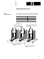
31.2 Understanding the QuickView Templates . . . . . . . . . . . . . . . . . . . . . . . . . . . . . . . . . . . . . . . . .
31-1
31-2
31-3
31-6
31-9
31-12
31-17
31-25
31-25
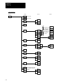
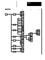
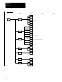
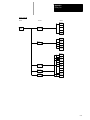
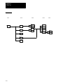
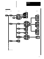
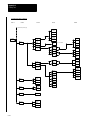
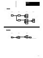
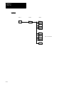
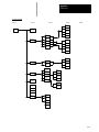
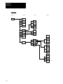
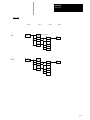
Appendix A
Softkey Tree
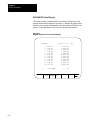
Appendix Overview . . . . . . . . . . . . . . . . . . . . . . . . . . . . . . . . . . . . . . . . . . . . . . . . . . . . . . . . . . . .
Understanding Softkeys . . . . . . . . . . . . . . . . . . . . . . . . . . . . . . . . . . . . . . . . . . . . . . . . . . . . . . . . .
Describing Level 1 Softkeys . . . . . . . . . . . . . . . . . . . . . . . . . . . . . . . . . . . . . . . . . . . . . . . . . . . . . .
Using the Softkey Tree . . . . . . . . . . . . . . . . . . . . . . . . . . . . . . . . . . . . . . . . . . . . . . . . . . . . . . . . .
A-1
A-1
A-3
A-3
Appendix B
Error and System Messages
Overview . . . . . . . . . . . . . . . . . . . . . . . . . . . . . . . . . . . . . . . . . . . . . . . . . . . . . . . . . . . . . . . . . . .
B-1
Appendix C
G-code Tables
Appendix Overview . . . . . . . . . . . . . . . . . . . . . . . . . . . . . . . . . . . . . . . . . . . . . . . . . . . . . . . . . . . .
G-code Tables . . . . . . . . . . . . . . . . . . . . . . . . . . . . . . . . . . . . . . . . . . . . . . . . . . . . . . . . . . . . . . .
xii
C-1
C-1
Table
of Contents
Index
(General)
9/Series
Mill
9/Series
PAL
Reference Manual
Operation and Programming Manual
Appendix D
Allen-Bradley 7300 Series CNC Tape Compatibility
Appendix Overview . . . . . . . . . . . . . . . . . . . . . . . . . . . . . . . . . . . . . . . . . . . . . . . . . . . . . . . . . . . .
G-code Compatibility Considerations . . . . . . . . . . . . . . . . . . . . . . . . . . . . . . . . . . . . . . . . . . . . . . . .
M-code Compatibility Considerations . . . . . . . . . . . . . . . . . . . . . . . . . . . . . . . . . . . . . . . . . . . . . . .
Offset Compatibility Considerations . . . . . . . . . . . . . . . . . . . . . . . . . . . . . . . . . . . . . . . . . . . . . . . . .
Additional Feature Compatibility Considerations . . . . . . . . . . . . . . . . . . . . . . . . . . . . . . . . . . . . . . . .
9/Series G-codes Applicable to the 7300 Series CNC . . . . . . . . . . . . . . . . . . . . . . . . . . . . . . . . . . . .
7300 Series Features Not Supported . . . . . . . . . . . . . . . . . . . . . . . . . . . . . . . . . . . . . . . . . . . . . . .
D-1
D-1
D-3
D-4
D-6
D-9
D-10
xiii
TableIndex
of Contents
(General)
9/SeriesManual
Mill
9/Series PAL Reference
Operation and Programming Manual
xiv
Chapter
1
Using This Manual
1.0
Chapter Overview
This chapter describes how to use this manual. Major topics include:
how the manual is organized and what information can be found in it.
how this manual is written and what fundamentals are presumed to be
understood by reader.
definitions for certain key terms.
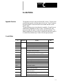
1.1
Audience
We intend this manual for use by those who program and/or operate any one
of the family Allen-Bradley 9/Series CNCs. We assume that a person has
some familiarity with the operation and programming of a CNC.
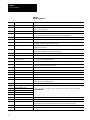
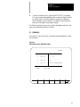
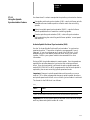
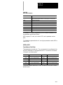
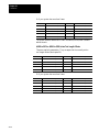
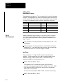
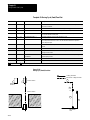
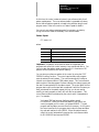
1.2
Manual Design
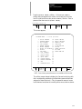
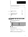
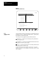
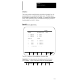
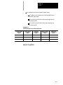
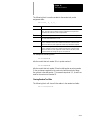
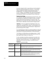
We divided the manual this way:
For information about:
Refer to:
how to operate the control
chapters 3 - 9
how to program the control
chapters 10 - 29
softkeys
appendix A
error and operator messages in alphabetical order
appendix B
standard G-codes used to program the control
appendix C
the Allen-Bradley 7300 Series CNC tape reader
appendix D
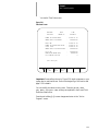
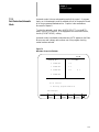
We placed section headings in the left margin of each page, and included
illustrations and examples as aids in programming and operating the
control.
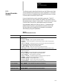
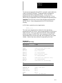
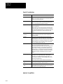
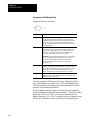
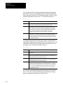
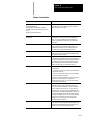
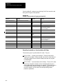
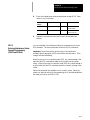
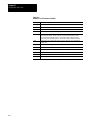
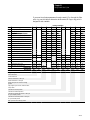
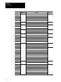
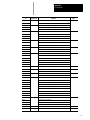
Table 1.A provides a summary of each chapter.
1-1
Chapter 1
Using This Manual
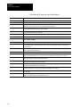
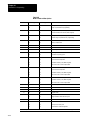
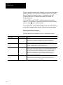
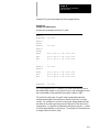
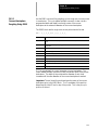
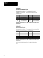
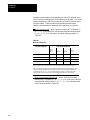
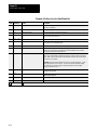
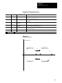
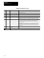
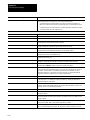
Table 1.A
Manual Organization
Chapter
1-2
Title
Summary
1
Manual Overview
Manual overview, intended audience, definition of key terms, how to proceed.
2
Basic Control Operation
A brief description of the control’s basic operation including power up, MTB panel, operator panel,
access control, and E-STOP.
3
Offset Tables and Setup
Basic setup of the offset table, other initial operating parameters.
4
Manual and MDI Operation
How to use the manual operate mode including, homing the machine, jog hand-wheel, jog
continuous, and jog increment. Also covered are the basics for MDI operation.
5
Editing Programs On Line
How to create, edit,and save a part program on line.
6
Editing Part Program Off Line
How to create, edit, and save a part programs from ODS off line.
7
Running a Program
How to select and execute a program automatically. This covers program checking as well as part
production. Also details on special running conditions.
8
Displays/ Graphics
How to access and interpret the different position displays. How to use the Quick Check and Active
Program graphics features.
9
Communications
Communications with peripheral devices. Includes sections on communication port parameters,
inputting and outputting AMP, PAL, Offsets, and programs.
10
Introduction to Programming
Tape format, structure and format of the programming language for the control.
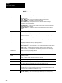
11
Coordinate System Offsets
Machine coordinate system, Preset Work coordinate systems, PAL offsets, and external offsets
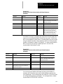
12
Overtravels and Programmable
Zones (G22, G23)
Hardware and software overtravels, programmable zone 2 (G22, G23), programmable zone 3
(G22.1, G23.1), and resetting overtravels
13
Coordinate Control
Describes absolute/incremental modes, inch/metric modes, radius/diameter modes, and scaling
14
Axis Motion
G-words define how the tool is positioned to the endpoint of a move. Also sections on automatic
machine home, dwell, mirroring, and axis clamp
15
QuickPath Plus
Describes QuickPath Plus programming
16
Using Chamfers and Corner Radius
Describes the ,C- and ,R-words programmed for chamfering and corner radius
17
Spindles
Describes spindle speed control, spindle orientation, spindle direction, and Virtual C axis
18
Programming Feedrates
Describes acc/dec, AMP-assigned feedrates, feedrate control, short block acc/dec
19
Dual Axis Operation
Describes parking, homing, programming, offset management for a dual axis
20
Tool Control
Selecting a tool. Activating and deactivating tool length offsets. Also tool control features such as
Random Tool and Tool Life Management.
21
Cutter Compensation
Describes the Tool Tip Radius Compensation feature (TTRC) that offsets for different tool diameters.
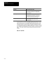
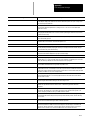
22
Using Pocket Milling Cycles
23
Using Post Milling Cycles
24
Using Hemisphere Milling Cycles
25
Using Irregular Pocket Milling Cycles
26
Milling Fixed Cycles
27
Skip and Gauging Cycles
Describes the 9/Series Probing features. Includes the tool measuring gauge feature.
28
Paramacros
Describes paramacros including calling, arithmetic functions, looping, decision making
29
Program Interrupts
Describes the program interrupt feature. This feature is used to call a subprogram or paramacro
program whenever a signal corresponding to that program is sent to PAL by the operator.
30
Dual Processing Systems
Necessary information on capabilities and programming methods for dual processing systems.
31
Transfer Line Cycles
Describes operation and programming of T-Line-9 part program templates for transfer line controls.
Describes the fixed cycles (canned cycles) for drilling operations and the G-words and parameters
used to define them.
Chapter 1
Using This Manual
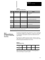
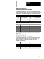
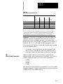
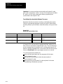
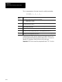
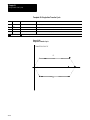
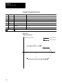
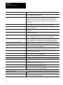
Table 1.A (cont.)
Manual Organization
Appendix
Title
Summary
Appendix A
Softkeys
Describes softkeys and their functions for softkey levels 1 and 2. Also the softkey tree displaying all
levels of softkeys and their location is shown.
Appendix B
Error and Operator Messages
An alphabetical listing of 9/Series system messages with brief descriptions.
Appendix C
G and M Code Tables
Lists the G-codes used to program the control.
Appendix D
A-B 7300 Series CNC Tape Reader
Detailed 7300 Series CNC tape compatibility feature developed on the control.
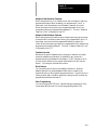
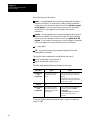
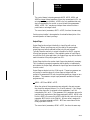
1.3
Reading this Manual
To make this manual easier to understand, we included these explanations
of terms and symbols:
All explanations, illustrations, and charts presented are based on
standard CNC functions. Operations may differ from the basic
information provided in this manual depending on the configuration of
the machine tool. For details, refer to the manuals prepared and supplied
by the system installer.
Some of the softkey functions may be purchased as optional features.
This manual assumes that all of the optional features have been
purchased.
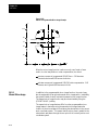
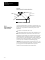
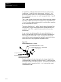
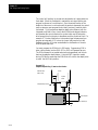
Explanations and illustrations are presented based on the movement of
the cutting tool on a fixed workpiece.
The control allows the use of any alphabetic character for expressing a
numerically controlled axis. This manual uses X, Y, and Z for the first,
second, and third axes on the basic coordinate system respectively. I, J,
and K represent the integrand words for the axes.
The term AMP is an abbreviation for Adjustable Machine Parameters.
These parameters are used to configure a control to a specific machine.
Setting of AMP is usually done by the system installer.
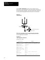
Key names designated between the [ ] symbols are found on the
operator panel.
Key names designated between the { } symbols are softkeys found
below the CRT.
Switch and button names on the standard MTB panel are designated
between the < > symbols.
1-3
Chapter 1
Using This Manual
The term PAL is an abbreviation for Programmable Application Logic.
This is a ladder logic program that processes signals between the CNC
and the machine. It is usually programmed by the system installer.
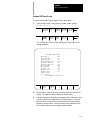
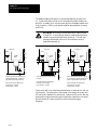
System Characteristics:
Metric
Absolute
IPM
1.4
Terms and Conventions
To make this manual easier to read and understand, we shortened the full
product names and features. Shortened terms include:
AMP — Adjustable Machine Parameters
Backup — Memory storage area not requiring battery maintenance
CNC — Computer Numerical Control
CPU — Central Processing Unit (the computing part of the control)
CRT — Cathode Ray Tube (the control’s monitor screen)
the control — the 9/230, 9/240, 9/260 or 9/290 CNC
ESTOP — Emergency Stop
Flash memory — programmable, non-volatile memory
HPG — Hand Pulse Generator
I/O — Input/Output
MDI — Manual Data Input
modal — an operating condition that remains in effect on the control
until cancelled or replaced
MTB — Machine Tool Builder
ODS — Offline Development System
PAL — Programmable Application Logic
RAM — Random Access Memory resident on the 9/240
softkeys — the row of keys directly below the screen
system installer — the company or contractor responsible for installing
this control on the machine
1-4
Chapter 1
Using This Manual
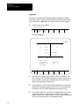
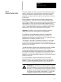
1.5
Warnings, Cautions, and
Important Information
We indicate information that is especially important by the following:
WARNING: indicates circumstances or practices that can lead
to personal injury as well as to damage to the control, the
machine, or other equipment.
CAUTION: indicates circumstances or practices that can lead
to damage to the control or other equipment.
Important: indicates information that is necessary for successful
application of the control.
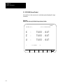
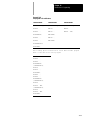
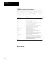
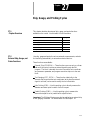
1.6
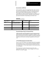
Related Publications
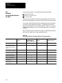
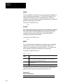
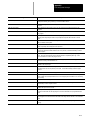
9/Series Documentation
Pub. No.
Document Name
8520-4.3
9/Series CNC PAL Reference Manual
8520-- 5.1.1
9/Series CNC Lathe Operation and Programming Manual
8520-- 5.1.3
9/Series CNC Mill Operation and Programming Manual
8520-- 5.1.4
9/Series CNC Grinder Operation and Programming Manual
8520-5.1.5
9/Series Data Highway Plus Communication Module User Manual
8520-5.1.6
9/Series MMS/Ethernet Communication Module User Manual
8520-- 5.2
9/Series CNC OCI User Manual Supplement
8520-6.2
9/Series CNC Integration and Maintenance Manual
8520-6.4
9/Series CNC AMP Reference Manual
8520-6.5
T-Line-9 Transfer Line Quick Start Guide
8520-- 6.6
9/Series CNC OCI Installation Manual
8520-- 6.7
9/Series CNC OCI API Developer’s Guide
MCD-5.1
Offline Development System User’s Manual
END OF CHAPTER
1-5
Chapter 1
Using This Manual
1-6
Chapter
2
Basic Control Operation
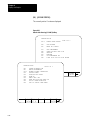
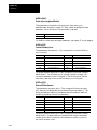
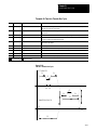
2.0
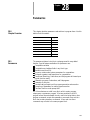
Chapter Overview
This chapter describes how to operate the Allen-Bradley 9/Series control,
including:
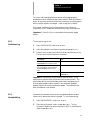
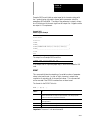
Topic:
On page:
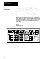
MTB panel
2-12
{FRONT PANEL}
2-15
Power-up
2-23
Emergency stops
2-24
Access control
2-25
Changing modes
2-33
Display system and messages
2-37
Input cursor
2-41
{REFORM MEMORY}
2-41
Removing an axis
2-43
Time part count
2-43
We also tell you about the control conditions automatically assumed at
power up.
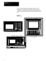
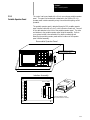
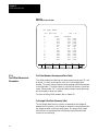
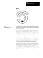
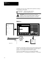
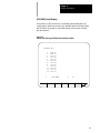
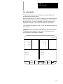
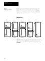
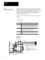
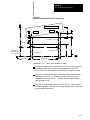
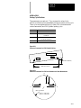
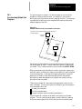
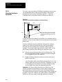
2.1
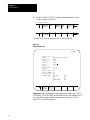
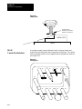
Operator Panel Operations
Use the operator panel to perform these operations:
display a part program
display control status and tool position
edit a part program
display and enter tool offset data
display the status of input/output signals
display and enter programmable zone boundaries
set the level of protection of part programs, tool offset data, AMP data,
etc.
Use the operator panel to perform many other operations. We describe
these operations in the remaining chapters of this manual.
2-1
Chapter 2
Basic Control Operation
Figure 2.1 shows the different operator panels available. The color
operator panel has identical keys and softkeys in a slightly different
configuration. The portable operator panel has the same key locations as
the monochrome operator panel but can be removed from the 9/Series I/O
ring.
Figure 2.1
Operator Panels
9/SERIES
8
9
4
5
6
1
2
3
.
0
:
7
Monochrome Operator Panel
Removable Operator Panel
+
O
_
$
!
=
X
_
P
CALC I
N
G
F
Y
Z
A
Q
R
W
J
K
M
E
D
?
B
[
S
SHIFT
]
H
#
C
L
T
SP
,
&
EOB DEL CAN RES
) LINE
CNTRL
TRANSMIT
DISP PROC
(
SELECTSELECT
Color Operator Panel
(CRT and Flat Panel)
2-2
19436
Chapter 2
Basic Control Operation
2.1.1
Keyboard
Table 2.A explains the functions of keys on the operator panel keyboard.
In this manual, the names of operator panel keys appear between [ ]
symbols.
Table 2.A
Key Functions
Key Name
Function
Address and Numeric Keys
Use these keys to enter alphabetic and numeric
characters. If a key has two characters printed on it,
pressing it normally enters the upper left character. Holding
down the [SHIFT] key while pressing it enters the lower
right character.
Cursor Keys • , • , • , •
Use these keys to move the cursor left, right, up and down
in the data display area (lines 4-21) of the screen. We
refer to these keys as the left, right, up, and down cursor
keys respectively.
[SHIFT] and • or •
Press the right or left cursor keys while holding down the
[SHIFT] key to move the cursor right and left on any
line on which that data is being input. (normally screen
lines 2-3).
[SHIFT] and • or •
Press the up or down cursor key while holding down the
[SHIFT] key to roll the display page forward or
backwards.
Calculation Key [CALC]
Pressing this key enables a calculator type function on the
control. Basic mathematical expressions may be evaluated
using this feature. For details, see page 2-4 .
Delete Key [DEL]
Pressing this key deletes the character to the left of the
cursor on input lines.
[SHIFT] and [DEL]
Pressing this key deletes all keyed-in data currently
displayed on input lines.
[CAN]
Clear the most recently generated, active error message
Transmit Key [TRANSMIT]
The data entered and displayed on the input lines is sent to
the control when the [TRANSMIT] key is pressed, for
example a password or a program block.
Block Reset [RESET]
This performs a block reset. See page 2-4 .
Control Reset [RESET] +
[SHIFT]
Pressing the reset key while holding down the shift key
performs a control reset. See page 2-4 for details.
Display Select
[DISP SELECT]
Use this key to display the different axis position display
softkeys.
End of Block [E.O.B.]
Use this key to enter an End of Block character when
editing a program or when writing an MDI program.
[PROC SELECT]
This key is used for dual process lathe systems only.
Pressing this key toggles the control from process to
process.
[SHIFT] and [• ]
Press the [SHIFT] key while holding down the [• ]
softkey to jump to the online search monitor screen. Press
these keys again to return to the previous screen.
2-3
Chapter 2
Basic Control Operation
Reset Operations
Block Reset
Use the block reset feature to force the control to skip the block execution.
To use the block reset function, program execution must be stopped. If
program execution stops before the control has completely finished the
block execution, a block reset aborts any portion of that block that has not
been executed. If program execution stops after the complete block
execution (as in the case of single block execution or a M00 etc.), the
control aborts the execution of the entire following block.
Press [RESET] key on the operator panel to perform a block reset.
Control Reset
You can return the control to the default parameters, clear any
programming errors, and cancel any MDI commands by executing a
control reset. After you execute a control reset, any active program resets
to the first block; any programmed offsets or rotations of the coordinate
systems reset to default, and any MDI command is discarded. All of the
operating parameters return to the standard AMP-assigned values,
including any AMP-assigned G-codes active at power-up (except
Inch/Metric which remains in its last programmed state at control reset).
Press the [RESET] key on the operator panel while holding down the
key to execute a control reset.
[SHIFT]
2.1.2
Calculator Function
The 9/Series control is equipped to evaluate simple mathematical
expressions during the course of operation or programming.
To use the calculator function, line 2 of the screen must be blank. There
can be no prompt on the input line of the screen when you attempt to do
calculations. This completely disables any calculation operation when in
MDI mode. If you attempt to enter the calculator function while another
prompt is active, the control generates the error message “CANNOT
CALCULATE - PROMPT PRESENT.”
Use the calculator function as follows:
2-4
1.
Press the [CALC] key on the operator panel. The “CALC:” prompt
appears on the input line of the screen (line 2).
2.
Enter a mathematical equation on the input line by pressing the
desired keys on the operator panel.
3.
Press the [TRANSMIT] key to evaluate the expression. The answer to
the expression is displayed on the input line.
Chapter 2
Basic Control Operation
Expressions entered on the input line cannot exceed a total of 25
characters. Only numeric or special mathematical operation characters as
described below can be entered next to the “CALC:” prompt. Any
character that is not numeric or an operation character you enter on the
input line generates the error message “INVALID CHARACTER.”
The largest number you can enter for a calculate function is 214748367.
You cannot enter a number larger than 10 digits. If control displays a
number that is too large (longer than 10 digits), the control displays the
error message “NUMBER IS OUT OF RANGE”. If the number entered or
calculated is greater than 10 digits, control displays the error message
“MATH OVERFLOW.”
Any fractional numbers cannot exceed .999999 (6 decimal places). If you
exceed this number of decimal places, the control automatically rounds off.
If this seventh digit is less than 5, the control rounds down. If this seventh
digit is 5 or greater, the control rounds up.
Any data entered on the input lines can be edited as described on page
2-41.
To disable the calculator function, press the [CALC] key again. The
“CALC:” prompt is removed from the input line.
Use the characters in Table 2.B to indicate mathematical operations.
Table 2.B
Mathematical Operators
*
Multiplication
/
Division
+
Addition
-
Subtraction
[]
Brackets
#
Get Paramacro Value
The control executes mathematical operations in this order:
1.
Any part of the expression that is between the brackets [ ] is
evaluated first. The values of paramacro variables are also
substituted for the #xxxx as the first operation performed.
2.
Multiplication and division are evaluated second.
3.
Addition and subtraction are evaluated last.
If the same level of evaluation is performed the left most operation takes
priority.
2-5
Chapter 2
Basic Control Operation
Example 2.1
Mathematic Expressions
Expression Entered
Result Displayed
12/4*3
9
12/[4*3]
1
12+2/2
13
[12+2]/2
7
12-4+3
11
12-[4+3]
5
Table 2.C lists the function commands available with the [CALC] key.
Table 2.C
Mathematical Functions
Function
Meaning
SIN
Sine (degrees)
COS
Cosine (degrees)
TAN
Tangent (degrees)
ATAN
Arc Tangent (degrees)
ASIN
Arc Sine (degrees)
ACOS
Arc Cosine (degrees)
SQRT
Square Root
ABS
Absolute Value
BIN
Conversion from Decimal to Coded Decimal
BCD
Conversion from Coded Decimal to Decimal
ROUND
Rounding Off (nearest whole number)
FIX
Truncation Down
FUP
Truncation Up
LN
Logarithms (natural log)
EXP
Exponent
When you program these functions, place the value that the function is to
be performed on in brackets, for example, SIN [10]. The exception to this
is the arc tangent function. The format for ATAN requires the division of
two values. For example, ATAN [10]/[2] is used to calculate the arc
tangent of 5.
The functions in Table 2.C are executed from left to right in a program
block. These functions are executed before the control executes any
mathematical operators like addition or subtraction. This order of
execution can only be changed by enclosing operations in brackets [ ].
Operations enclosed in brackets are executed first.
2-6
Chapter 2
Basic Control Operation
Example 2.2
Format for [CALC] Functions
SIN[2]
This evaluates the sine of 2 degrees.
SQRT[14+2]
This evaluates the square root of 16.
SIN[SQRT[14+2]]
This evaluates the sine of the square root of 16.
Example 2.3
Mathematical Function Examples
Expression Entered
Result
SIN[90]
1.0
SQRT[16]
4.0
ABS[-4]
4.0
BIN[855]
357.0
BCD[357]
855.0
ROUND[12.5]
13.0
ROUND[12.4]
12.0
FIX[12.7]
12.0
FUP[12.2]
13.0
FUP[12.0]
12.0
LN[9]
2.197225
EXP[2]
7.389056
Important: Precaution must be taken when performing calculations within
the brackets [ ]. The operations within the bracket are performed first, and
then the function is performed on this resultant. For example
ROUND[2.8+2.6];
The result of this is 5.0
The values in the brackets are added together first and then rounded, not
rounded and then added together.
Paramacro Variables in CALC Operations
Any paramacro variable can be accessed through the CALC function.
Include a # sign followed by the paramacro variable number. When the
calculation is performed the value of that paramacro variable is substituted
into the equation. You can not change the value of paramacro variables
with the CALC function. Local parameters are only available for the
currently active nesting level of the control (main program, or one of four
nested macro programs). You can not perform calculations that contain
any paramacro variables if the control is currently executing a program
block. The control must be in either cycle stop state, or E-Stop.
2-7
Chapter 2
Basic Control Operation
Example 2.4
Calling Paramacro Variables with the CALC Function
Expression Entered
2.1.3
Softkeys
Result Displayed
#100
Display current value of variable #100
12/#100*3
Divide 12 by the current value of #100
and multiply by 3
SIN[#31*3]
Multiply the value of #31 (for the current
local parameter nesting level) by 3 and
take the sine of that result
We use the term softkey to describe the row of 7 keys at the bottom of the
CRT. Each function is displayed on the CRT directly above the softkey.
Softkey names are shown between the { } symbols in this manual.
The control offers a variety of functions that can be initiated by using the
softkeys. The operator panel has 5 softkeys whose function names are
displayed in the softkey area at the bottom of the screen (lines 23-25 — see
Figure 2.2).
Figure 2.2
Softkeys
Data display area
Softkey name display area
PRGRAM
MANAGE
Exit
OFFSET
MACRO
PARAM
Softkeys
PRGRAM
CHECK
SYSTEM
SUPORT
Continue key
We often describe softkeys as being on a certain level, for example softkey
level 3. We use the level of the softkey to determine the location or
necessary path to reach that particular softkey function. For example, to
get to a softkey on level 3, you must press a specific softkey on level 1,
followed by a specific softkey on level 2. For a listing of all the softkeys
and their respective levels, refer to appendix A.
2-8
Chapter 2
Basic Control Operation
Softkey level 1 is the initial softkey level the control displays at power-up.
Softkey level 1 always remains the same and all other levels are referenced
from softkey level 1.
The softkeys on opposite ends of the softkey row have a specific use that
remains standard throughout the different softkey levels.
On the:
Is the:
left
exit softkey displayed with the up arrow {• }
right
continue softkey displayed with the right arrow {• }
Use the exit softkey {• } on the far left to regress softkey levels. For
example, if you are currently on softkey level 3 and you press the exit
softkey, the softkeys change to the softkeys previously displayed on
softkey level 2. When you press the exit softkey while holding down
the shift key, the softkey display is returned to softkey level 1 regardless
of the current softkey level.
When more than 5 softkey functions are available on the same level, the
control activates the continue {• } softkey at the far right of the softkey
area. When you press the continue softkey, the softkey functions
change to the next set of softkeys on that level.
Important: The continue softkey is not active when the number of softkey
functions on that level does not exceed 5.
For example:
(softkey level 1)
PRGRAM OFFSET MACRO
MANAGE
PARAM
PRGRAM SYSTEM
CHECK SUPORT
When softkey level 1 is reached, the above set of softkeys is displayed.
Pressing the continue softkey {• } displays the remaining softkey
functions on softkey level 1.
(softkey level 1)
FRONT
PANEL
ERROR PASSMESAGE WORD
SWITCH
LANG
The exit softkey is not displayed since the softkeys are already on softkey
level 1.
The softkey functions for level 1 and level 2 are explained in appendix A.
Softkey functions for level 3, or higher, are explained in the sections that
apply to their specific operations.
2-9
Chapter 2
Basic Control Operation
To use a softkey function, press the plain, unmarked button directly below
the description of the softkey function.
Important: Some of the softkey functions are purchased as optional
features. This manual assumes that all available optional features have
been purchased for the machine. If an option is not purchased, the softkey
is blank.
2.1.4
CRT
The control can be purchased with a 9-inch monochrome monitor or a
12-inch color monitor.
Certain lines of the screen are dedicated to displaying specific information:
2-10
Lines:
Display information:
line 1
machine/
system message area
If an error occurs or a message is generated for any reason during
machine operation or program execution, the control displays the
corresponding machine/system message in this area. Only the
highest priority, most current message is displayed here.
lines 2-3
input lines
When you enter data using the keyboard, the control displays the
characters corresponding to the keys pressed until you press the
[TRANSMIT] key. Some screens can only have line 2 as an input
line.
lines 4-20
data display area
The control displays axis position data, listing of the part program, tool
offset data, G-, M-, H-, T-, F-, S-, and D-codes, graphics, and other
data, as determined by the selected display. See chapter 8.
lines 21-22
PAL message area
The control displays any messages generated by the control’s PAL
program in this area
lines 23-25
softkey display area
The control displays the currently available softkey functions in this
area.
Chapter 2
Basic Control Operation
2.1.5
Portable Operator Panel
The control can be purchased with a 9-inch monochrome portable operator
panel. This panel can be attached or detached to the 9/Series I/O ring
operator panel interface assembly at any time without disrupting control
operation.
The portable operator panel is attached through a 10 ft portable operator
panel interface cable with a 3--pin D--shell connector at each end. One end
of the cable attaches to the front of the portable operator panel. The other
end attaches to the portable operator panel interface assembly. Refer to
your system installer’s documentation for details on attaching and
detaching the portable operator panel and the locations of the operator
panel interface assembly.
Removable Operator Panel
Connect Interface Assembly
(37 pin D Shell has pins)
Interface Assembly
Vidoe Out CN4
Operator Pnl. CN5
GND12V GND5VGND 5V GND 5V CHA L
H
GND AC
Video In CN19M
Connect Operator Panel
(37 pin D Shell has sockets)
2-11
Chapter 2
Basic Control Operation
2.2
The MTB Panel
Figure 2.3 shows the push-button MTB panel. Table 2.D explains the
functions of the switches and buttons on the MTB panel. Other optional or
custom MTB panels may be used. Refer to the documentation prepared by
your system installer for details.
We show button names found on the push--button MTB panel between the
< > symbols throughout this manual. The push-button MTB panel uses
defaults when you turn on power to the control. Table 2.D contains these
defaults.
Most of the switches or buttons on the MTB panel are configured by your
system installer’s PAL program. We assume that PAL has been written as
intended for normal operation. If a switch or button does not work the way
it is described in this manual, refer to documentation prepared by your
system installer.
Figure 2.3
Push-Button MTB Panel
MODE SELECT
AUTO
MDI
JOG SELECT
MAN
INCR
CONT
HAND
HOME
SPINDLE SPEED
OVERRIDE
SPEED/MULTIPLY
LOW
X1
MEDL
X10
MEDH
X1000
AXIS
SPINDLE
MED
X100
HIGH
X10000
CCW
50
FUNCTION
CYCLE
START
+X
+4
--X
F1
F2
SINGLE
BLOCK
+Y
TRVRS
--Y
F3
F4
CYCLE
STOP
+Z
--4
--Z
F5
F6
FEEDRATE
OVERRIDE
50
ESTOP
RESET
OFF
120
ON
CW
OFF
RAPID FEEDRATE
OVERRIDE
100
0
150
F1
25
50
100
%
19930
2-12
Chapter 2
Basic Control Operation
Table 2.D
Functions of the Buttons on the Push-Button MTB Panel
Switch or Button Name
MODE SELECT
How It Works
= Default for Push-Button MTB Panel
Selects the operation mode
AUTO - - automatic mode
MANUAL - - manual mode
MDI - - manual data input mode
JOG SELECT
Selects the jog method to be active in manual mode
HANDWHEEL - - HPG (hand pulse generator) jog
INCREMENTAL - - incremental jog
CONTINUOUS - - continuous jog
HOME - - machine home
SPEED/MULTIPLY
Selects an axis feedrate or axis feed amount multiplication ratio used in the manual mode. Each
selection modifies the active feedrate by a value set in AMP. Modification also depends on the setting
of <JOG SELECT> as described below:
• HANDWHEEL
When in handwheel jog mode, SPEED/MULTIPLY alters the handwheel resolution by a factor
determined in AMP. Your system installer sets the value for:
- LOW X1
- MEDL X10
- MEDL X100
You cannot use the values listed below for handwheel jog:
- MEDH X1000
- HIGH X10000
• INCREMENTAL
When in incremental jog mode, SPEED/MULTIPLY alters the incremental jog distance by a factor set
in AMP by your system installer. Your system installer sets a value for the selections. The
incremental jog speed is fixed to medium but can still be controlled by
<FEEDRATE OVERRIDE>.
• CONTINUOUS
When in continuous jog mode, SPEED/MULTIPLY acts as a feedrate selection switch which has
values set in AMP by your system installer. Your system installer sets a value for all 5 selections
independently for each axis. <FEEDRATE OVERRIDE> can be used for speed adjustments.
Important: The values for the different <SPEED/MULTIPLY> selections are configured by
your system installer.
2-13
Chapter 2
Basic Control Operation
Table 2.D
Functions of the Buttons on the Push-Button MTB Panel
Switch or Button Name
How It Works
= Default for Push-Button MTB Panel
SPINDLE SPEED OVERRIDE
Selects the override for programmed spindle speeds in 5% increments within a range of 50% to 120%.
SPINDLE or
SPINDLE DIRECTION
Selects spindle rotation, clockwise (CW), spindle stop (OFF), counterclockwise (CCW). Can be
overridden by any programmed spindle direction command.
FEEDRATE OVERRIDE
Selects a feedrate override percentage for the feedrate programmed with an F-- word in any of the
feedrates modes (G93/G94/G95) and the reciprocation feedrate programmed with an E-- word.
<FEEDRATE OVERRIDE> has a range of 0% to 150% of the programmed feedrate and alters the
programmed feedrate in 10% increments. When set to 0%, the control is effectively in feedhold.
RAPID FEEDRATE OVERRIDE
Selects the override for rapid feedrates. Select from F1, 25%, 50%, and 100% where F1 is a rapid
feedrate override setting established in AMP by the system installer.
EMERGENCY STOP
This button stops machine operation and disables the spindle and axis drives when pressed.
E-STOP RESET
This button resets an emergency stop condition when pressed. Before pressing this button the
condition that caused the E-Stop should be resolved.
CYCLE START
The control begins or resumes part program execution, MDI program execution, or program check
when this button is pressed.
CYCLE STOP
The control stops part program execution, MDI execution, or program check when this button is
pressed. If pressed during the execution of a program block a cycle suspend state occurs.
SINGLE BLOCK
The control executes or checks one block of a part program or MDI entry each time the
<CYCLE START> button is pressed when single block is active.
AXIS/DIRECTION
These buttons are used for manual operations. They select an axis and direction when
<JOG SELECT> is set for continuous, incremental, or home. If <JOG SELECT> is set for
handwheel, these buttons select an axis only. Direction is then determined by handwheel rotation.
TRVRS
Hold this button down while executing a continuous jog move to override the active feedrate and jog an
axis in rapid traverse.
F1 - F4
The functions for these buttons are assigned by the system installer. Refer to the documentation
prepared by the system installer for details.
JOG RETRACT
Use jog retract to jog a cutting tool away from the workpiece during automatic or MDI program
execution. The control can retrace the jog moves and return the cutting tool automatically to the
workpiece by pressing <CYCLE START>. Refer to chapter 7 for more on this.
BLOCK RETRACE
To retrace the tool path in a part program already executed (up to 15 blocks), press this button.
ON
Turns on power to the control.
OFF
Turns off power to the control.
Important: Many of the override switch settings may be disabled by
programming the correct M-code or setting a particular paramacro
parameter. Refer to their respective sections for details on these features.
2-14
Chapter 2
Basic Control Operation
2.3
Software MTB Panel
{FRONT PANEL}
The 9/Series control offers a software MTB panel that performs many of
the functions of an MTB panel. This feature uses softkeys instead of the
normal switches and buttons of a panel. If the control uses a standard
MTB panel (described on page 2-12), or some other custom panel, the
requests for operations from the panel takes priority. This means that
requests of the software MTB panel are ignored if another request is sent
from a standard or custom MTB panel.
The software MTB panel’s operation depends on PAL, especially if the
control uses either the standard or a custom MTB panel. Refer to
documentation prepared by your system installer for details on using the
software MTB panel. Your system installer uses PAL to disable the
{FRONT PANEL} softkey.
Important: By using the PAL flags $SWF1 and $SWF2, you can enable
and disable features available on the software front panel.
Refer to your PAL reference manual for additional information.
2-15
Chapter 2
Basic Control Operation
The software MTB panel can control these features:
Feature
2-16
Description
Mode Select
Select either Automatic, MDI, or Manual modes as the current operating mode of the control.
Rapid Traverse
This feature replaces the feedrate when executing a continuous jog move with the rapid feedrate.
Feedrate Override
Selects a feedrate override percentage for feedrates programmed with an F-word, in 10% increments within a
range of 0% to 150%. When set to 0%, the control is effectively in feedhold.
Rapid Feedrate Override
Selects the override for rapid feedrates. Select from F1, 25%, 50%, and 100%, where F1 is a rapid feedrate
override setting established in AMP by the system installer.
Spindle Direction
Selects spindle rotation, clockwise (CW), spindle stop (OFF), or counterclockwise (CCW). Is overridden by
any programmed spindle direction command.
Spindle Speed Override
Selects the override for programmed spindle speeds in 5% increments within a range of 50% to 120%.
Dry Run Mode
Places the control in Dry Run Mode. This replaces feedrates with the Dry Run feedrates. See chapter 7.
Block Delete
Allows the activation of the block delete feature “/ or /1”(See chapter 7). Block delete 2 - 9 are not available
with the {FRONT PANEL}.
M-Function Lock
Allows select M-, S-, T-, and B-codes to be ignored. See chapter 7.
Optional Stop
This enables or disables the M01 optional stop code. When this feature is “ON,”an M01 in a part program
stops automatic execution. When this feature is “OFF,”an M01 in a part program is ignored. See chapter 10
for details on M01.
Single Block
The control executes or checks one block of a part program or MDI entry each time the <CYCLE START>
button is pressed when this feature is on.
Mirror Image
Mirrors the axis commands in the part program around the selected axis. See chapter 14.
Axis Inhibit
Prevents axis commands from being executed. The control simulates axis motion on inhibited axes by using
Acc/Dec and feedrates; however, no actual axis motion for the inhibited axes is generated. See chapter 7.
Jog the Axes
Allows manual motions to be performed in any one of the jogging modes. See section 4.1. Multi-axis jogs
may not be performed by using the Software MTB feature.
Set Zero
Change the tool’s current position in the work coordinate system to 0 for the selected axis. This is done by
shifting the work coordinate system. See chapter 11.
Block Retrace
This allows up to 15 part program blocks to be retraced during program execution and allow the tool to
automatically re-execute these blocks. See chapter 7.
Jog Retract
Allow the tool to be manually jogged away from the part and then automatically return the tool to the part by
retracing the jogged moves. Up to 15 jog moves can be remembered. See chapter 7.
Cycle Start
The control begins or resumes part program execution, MDI program execution, or program check when you
press this button.
Cycle Stop
The control stops part program execution, or program check when you press this button. If pressed during the
execution of a program block, a cycle suspend state occurs.
Chapter 2
Basic Control Operation
Software MTB Panel Screen
To use the software MTB panel feature, follow these steps:
1.
From the main menu screen, press the {FRONT PANEL} softkey.
(softkey level 1)
PRGRAM OFFSET MACRO
MANAGE
PARAM
PRGRAM SYSTEM
CHECK SUPORT
FRONT
PANEL
SWITCH
LANG
ERROR PASSMESAGE WORD
The Software MTB Panel screen displays the current status of the
alterable features.
SOFTWARE FRONT PANEL
MODE SELECT:
MDI
RAPID TRAVERSE:
OFF
FEEDRATE OVR:
0%
RAPID FEEDRATE OVR:
100%
SPINDLE DIRECTION:
CW
SPINDLE SPEED OVR:
50%
DRY RUN MODE:
OFF
BLOCK DELETE:
OFF
M-FUNC LOCK:
OFF
OPTIONAL STOP:
OFF
SINGLE BLOCK:
OFF
MIRROR IMAGE:
AXIS INHIBIT:
USE CURSOR FOR SELECTION
JOG
AXIS
PRGRAM
EXEC
2.
Press the up or down cursor keys to select the function you want to
change. The selected function appears in reverse video.
3.
Alter the value of the function by pressing the left or right cursor keys
(except for the Mirror Image and Axis Inhibit features). When you
select the Mirror Image or Axis Inhibit features, the softkey names
change to the axis names. Press the softkey that corresponds to the
axis (or axes) that you want to assign to these features.
2-17
Chapter 2
Basic Control Operation
Jog Screen
We assume that you have performed the steps to display the Software
Front Panel screen. Make sure that the function selected on the Software
Front Panel screen is not the Mirror Image or the Axis Inhibit features.
1.
Press the {JOG AXIS} softkey.
(softkey level 2)
JOG
AXIS
PRGRAM
EXEC
This screen appears:
E-STOP
PROGRAM [mm]
F
0.000 MMPM
0.0
Z
0.000
S
R X
0.000
T 0
C
359.99
FILENAME
SUB NAME
MEMORY
MAN
AXIS SELECT:
JOG SELECT:
SPEED/MULTIPLY
HPG NUMBER
SET
ZERO
2-18
STOP
X
CONTINUOUS
LOW
0
JOG
JOG
AXIS + AXIS -
2.
Select the axis, jog type, speed multiply value (see chapter 4), and
HPG number (if HPG has been selected as the type of jog) by using
the up and down cursor keys, and the left and right cursor keys to
alter the value assigned to that function.
3.
If the jog type is not HPG, then press the softkey that corresponds to
the direction on the selected axis to jog (if HPG is the jog type then
the direction of HPG rotation determines the direction to jog).
4.
If you want to shift the current work coordinate system to force the
current tool position to be the zero point of the work coordinate
system, press the {SET ZERO} softkey. The {SET ZERO} softkey does
not function when the control is in handwheel mode.
Chapter 2
Basic Control Operation
Program Execute Screen
The following assumes that the steps have been performed to display the
Software Front Panel screen (see page 2-17). Make sure that the function
selected on the Software Front Panel screen is not the Mirror Image nor
the Axis Inhibit feature.
1.
Press the {PRGRAM EXEC} softkey.
(softkey level 2)
JOG
AXIS
PRGRAM
EXEC
This screen appears. Before you press this softkey, a program should
have already been selected for automatic execution as described in
chapter 7.
E-STOP
PROGRAM[ MM
]
F
0.000 MMPM
Z
0.000
S
0.0
R X
0.000
T 0
C
359.99
FILENAME
SUB NAME
MEMORY
MAN
STOP
M100;
G90;
Z10;
G70;
BLOCK JOG
CYCLE
RETRCE RETRCT START
CYCLE
STOP
2-19
Chapter 2
Basic Control Operation
2.
Select one of these softkey options:
block retrace
jog retract
cycle start
cycle stop
3.
To Perform a:
Press:
Cycle Start
the softkey that corresponds to the desired feature. Details on these
features are described in chapter 7.
Cycle Stop
the softkey that corresponds to the desired feature. Details on these
features are described in chapter 7.
Block Retrace
the {BLOCK RETRCE} softkey. The control automatically
retraces the previously executed block each time you press. The tool
returns to the start point of Block Retrace when you press the
{CYCLE START} softkey. Details on Block Retrace can be found
in chapter 7.
Jog Retract
the {JOG RETRCT} softkey. This calls up the jog retract screen.
Select: the axis, the type of jog, the speed multiply value (see
chapter 4), or the HPG number (if HPG has been selected as the
type of jog). Use the up and down cursor keys to select the function,
and the left and right cursor keys to alter the value assigned to that
function.
If you selected JOG RETRACT, press the {JOG AXES +} or
{JOG AXES -} softkeys to select the direction to jog the axis. Press
the exit {• } softkey when you complete the jog retract. The cutting
tool automatically retraces the jog moves you made when you pressed
the {CYCLE START}. See chapter 7.
(softkey level 4)
SET
ZERO
2-20
JOG
JOG
AXES + AXES-
Chapter 2
Basic Control Operation
Figure 2.4
Jog Retract Software MTB Panel Screen
E-STOP
PROGRAM[ MM
]
F
Z
00000.000
S
R X
00000.000
T
C
359.99
00000.000 MMPM
0
12
FILENAME
SUB NAME
MEMORY
JOG
AXES+
MAN
STOP
JOG
AXES-
2.4
Power Procedures
The basic procedure for turning power on and off is described in this
section. Refer to the documentation prepared by your system installer for
more specific procedures.
2.4.1
Turning Power On
Follow this procedure to turn on power to the control:
1.
Visually check to make sure that the control and the machine are in
normal operating conditions.
2.
Press the power <ON> button.
Important: Do not touch any other buttons after you press the power <ON>
button until characters appear and remain on the screen.
3.
If characters are not displayed on the screen within 15 seconds, press
the power <OFF> button immediately.
Important: If the screen does not display characters after you press the
power <ON> button within a reasonable warm up period (about 15 seconds),
immediately press the power <OFF> button and contact service personnel.
To activate the main menu, press the [TRANSMIT] key.
2-21
Chapter 2
Basic Control Operation
You see the main menu screen:
E-STOP
PROGRAM[ MM
]
F
Z
00000.000
S
R X
00000.000
T
C
359.99
00000.000 MMPM
12345
FILENAME
SUB NAME 9999
MEMORY 30000 MDI
STOP
(PAL messages)
PRGRAM OFFSET MACRO
MANAGE
PARAM
PRGRAM SYSTEM
CHECK SUPORT
The softkeys available on the main menu screen are referred to as “level 1”
softkey functions. Some of the softkey functions are purchased as optional
and may not appear exactly as shown.
2.4.2
Turning Power OFF
Follow this procedure to turn off power to the control:
CAUTION: To prevent damage to the machine, never turn off
power while a part program is being executed. Before turning
off power, make sure that the control is in CYCLE STOP.
2-22
1.
Before you turn the power off, make sure that the control is in
CYCLE STOP.
2.
Press the <EMERGENCY STOP> button.
3.
Make sure that power is turned off to all peripheral devices (tape
reader, tape punch, etc.) that are connected to the control.
4.
Press the power <OFF> button.
Chapter 2
Basic Control Operation
2.5
Control Conditions at
Power-Up
After powering up the control or performing a control reset operation (see
page 2-4), the control assumes a number of initial operating conditions.
These are listed below:
Initial Password Access is assigned to the level that was active when
power was turned off (provided that level is a power-up level selected in
access control). If the active level when power is turned off is not a
power-up level, then the control defaults to the next lower level that is a
power-up level. See page 2-25 on access control.
The control is placed in E-Stop. The control is not allowed to come out
of E-Stop if the default AMP is loaded at power-up, or if there is no
PAL program loaded in the system. An appropriate error message is
displayed.
The control defaults to one G-code from each of these groups
(as set in AMP):
Modal Group:
G-code
1
G00
G01
Rapid traverse
Linear interpolation
2
G17
G18
G19
Plane Selected
Plane Selected
Plane Selected
3
G90
G91
Absolute
Incremental
4
G22
G22.1
G23
G23.1
Programmable Zone 2 and 3 (On)
Programmable Zone 2 (Off) 3 (On)
Programmable Zone 2 and 3 (Off)
Programmable Zone 2 (On) 3 (Off)
5
G94
G95
Feed per minute
Feed per revolution
6*
G70
G71
Inch mode
Metric mode
18
G07
G08
Radius Programming Mode
Diameter Programming Mode
* This G code group is only established at power up. A control reset
will not change the last programmed state of this modal G code group.
To show the current operating conditions at any time, access the G-code
status screen as described in chapter 8. If you do this immediately after
power-up, it shows the initial operating conditions selected in AMP along
with other control power-up default conditions.
2-23
Chapter 2
Basic Control Operation
2.6
Emergency Stop Operations
Press the red <EMERGENCY STOP> button on the MTB panel (or any other
E-Stop switches installed on the machine) to stop operations regardless of
the condition of the control and the machine.
WARNING: To avoid damage to equipment or hazard to
personnel, the system installer should connect the
<EMERGENCY STOP> button, so that pressing the button opens the
circuit connected to the E-STOP STATUS terminal on the
control. This should disable the axis drives and the spindle
drive circuits, which should both be connected to this terminal.
Refer to the integration manual or the documentation prepared
by your system installer for details.
If equipped with the standard MTB panel, the following occurs
automatically after you press the <EMERGENCY STOP> button:
The control displays “E-STOP” in the message area. This indicates that
the control is in the emergency stop state.
The red light in the <CYCLE STOP> button lights up to indicate that the
control is in the feedhold state.
Power to all axis drive motors is turned off.
Important: If you press the <EMERGENCY STOP> button while a part
program is running, program execution can resume at the point of
interruption. Refer to the mid-program start feature described in chapter 7.
2.6.1
Emergency Stop Reset
Before resetting the emergency stop state, first locate and eliminate the
cause of the emergency stop.
If the <EMERGENCY STOP> button is locked in the pressed position, it must
be released before the emergency stop state can be reset. The locked
button can be released in different ways depending on its type. With the
standard MTB panel, turn the button clockwise until it pops out.
To reset the emergency stop state, press the <E-STOP RESET> button. Once
you push the E--Stop Reset button to clear the E--Stop state, the message,
“RESETTING E--STOP” displays to alert you that the control is attempting
to come out of E--Stop. After the cause of the E--Stop is resolved, the
control clears the “E--STOP” message. If the error condition is not cleared,
the “RESETTING E--STOP” message clears, but the “E--STOP” message
continues to flash as the control remains in E--Stop state.
2-24
Chapter 2
Basic Control Operation
If the E-Stop occurred during program execution, the control may reset the
program when E-Stop reset is performed provided AMP is configured to
do so. Assuming that a control reset is performed, program execution
begins from the first block of the program when <CYCLE START> is
pressed. If the current axis position prohibits this, the operator can
manually jog the axes clear, or consider executing a Mid-Program Start.
See chapter 7. If no control reset is performed, the remainder of the
program block being executed when E-Stop took place is aborted, and a
<CYCLE START> begins program execution at the next block.
Important: If the cause of the E-Stop is not eliminated, the circuit
connected to the E-STOP STATUS terminals remains open, and the
emergency stop state is not reset even when the <E-STOP RESET> button is
pressed.
2.7
Access Control
Access control lets the system installer assign different functions of the
control to different users by means of a password. See section 2.7.2 for a
list of the functions that may be protected on the 9/Series control.
Each protectable function is assigned an access level that is made active
when the operator enters the password. When an access level is made
active, all functions that are assigned to that access level become available.
Access levels range between 1 and 8 where 1 is the highest level and 8 is
the lowest. A different password is assigned to each of the different access
levels. Eight passwords can be assigned.
Access control only applies to the front panel and softkey inputs. It cannot
control inputs from outside the system. For instance, if you control access
to the delete function, the user can’t delete a file, but a file can be deleted
by Mini-DNC software and by Data Highway with the 9/Series Data
Highway Plus Communication Module.
Important: If you do not want to use password protection, simply select
all functions as accessible for access level 8. Since access level 8 is
automatically available at power up, no password is necessary to access
any of the functions of the control. Password protection can also be
disabled by assigning a level at the power-up level by using the
“POWER UP LEVEL” parameter as described in section 2.7.2.
2-25
Chapter 2
Basic Control Operation
2.7.1
Assigning Access Levels
and Passwords
This section describes setting or changing the functions assigned to a
particular access level, and changing the password used to activate that
access level.
Important: Functions or passwords can be assigned to another access
level only if:
If you have a higher access level than the access level you are
attempting to change, this means that if your password is assigned to
access level 6, you can only change the functions or passwords for
access levels 7 and 8. Functions, or a password, cannot be assigned to
access level 6 with a level 6 password.
Functions that are not available to the current user cannot be assigned to
other levels. If a user with access level 6 is changing a lower access
level functions, access level 6 must have access to any functions that are
changed. For example, if you are an access level 6 user, you do not
have access to {SYSTEM SUPORT}, you cannot assign or remove
{SYSTEM SUPORT} to access level 7.
The current user must have access to the {ACCESS CONTROL} function.
To change the functions or password of a lower user number, follow these
steps:
1.
Press the {PASSWORD} softkey.
(softkey level 1)
2-26
PRGRAM OFFSET MACRO
MANAGE
PARAM
PRGRAM SYSTEM
CHECK SUPORT
FRONT
PANEL
SWITCH
LANG
ERROR PASSMESAGE WORD
Chapter 2
Basic Control Operation
2.
Press the {ACCESS CONTRL} softkey. If the {ACCESS CONTRL}
softkey does not appear on the screen, the currently active access
level is not allowed to use the {ACCESS CONTRL} function. Enter a
password that has access to {ACCESS CONTRL}.
(softkey level 2)
ACCESS
CONTRL
This screen appears.
PASSWORD NAME -- (current password)
1
2
3
4
5
6
7
8
9
10
11
12
13
14
15
16
17
ACTIVE PROGRAM
PROGRAM MANAGE
EDIT PROGRAM
COPY PROGRAM
RENAME PROGRAM
DELETE PROGRAM
DELETE ALL PROGRAM
OFFSETS
TOOL WEAR
TOOL GEOMETRY
ACTIVE OFFSET
BACKUP OFFSET
QUICK CHECK
SYSTEM SUPPORT
PRGRAM PARAMETER
AMP
PARAMACRO PROG
UPDATE 01
& EXIT
02
18
19
20
21
22
23
24
25
26
27
28
29
30
31
32
33
34
ACCESS CONTROL
SWITCH LANGUAGE
POWER UP LEVEL
TIME PARTS
SI/OEM MESSAGE
SCALING
CHANGE DIRECTORY
AUX COMM
SEARCH MONITOR
03
04
NOTE: Some of these protected features are not available on 9/240 controls.
The softkey names change to display the 8 access levels along with
their corresponding passwords (provided that a password has been
assigned to that access level). Only the password names of access
levels that are lower than the currently active access level are shown.
2-27
Chapter 2
Basic Control Operation
3.
Press the softkey that corresponds to the access level that you want to
change. The pressed softkey appears in reverse video, and the
password name assigned to that access level is moved to the
“PASSWORD NAME.”
Important: If you attempt to change the functions available to an access
level that is equal to or higher than your the current access level, the error
message “ACCESS TO THIS LEVEL IS NOT ALLOWED.” You cannot
change the features that are assigned to your current access level or any
level that is higher than your own.
(softkey level 3)
UPDATE 01
02
03
04
& EXIT (NAME) (NAME) (NAME) (NAME)
4.
If you want to enter or change the password for the selected level,
edit the password next to the “PASSWORD NAME” prompt by using
the input cursor as described on page 2-41 . If you also want to
change the functions for this password, move on to step 5. To save
the change made to the password and leave the access control screen
press the {UPDATE & EXIT} softkey.
Functions that are currently available to the selected level are shown
in reverse video on the access level screen.
5.
Use the up, down, right, and left cursor keys to select the functions to
change for that access level. The selected function is shown with a
flashing > to the left of the function.
6.
Pressing the [TRANSMIT] key toggles the function between accessible
and inaccessible for that access level.
Important: If you attempt to activate or deactivate a function that is not
accessible to the current user’s access level, the message “ACCESS TO
THIS FUNCTION NOT ALLOWED” is displayed. Only features that are
accessible to your the current access level can be selected as accessible or
inaccessible to a lower access level.
7.
Press the {UPDATE & EXIT} softkey to store the changes made to
accessible functions for the user levels and return the control to
softkey level 1.
(softkey level 3)
UPDATE 01
02
03
04
& EXIT (NAME) (NAME) (NAME) (NAME)
2-28
Chapter 2
Basic Control Operation
2.7.2
Password Protectable
Functions
The following section describes the functions on the 9/Series control that
can be protected from an operator by the use of a password. If a user has
access to a function, the parameter associated with that function is shown
in reverse video on the access control screen.
Access to these functions can be controlled by passwords. Table 2.E
describes the function that is enabled (the operator can perform them) if
the parameter name is shown in reverse video. If the function is not shown
in reverse video, the function is protected and cannot be accessed.
Some parameters enable more than one function. If a parameter that
enables multiple functions is not selected as accessible, some of the
functions that would be enabled by the parameter can be enabled
individually by using other parameters.
Table 2.E
Password Protectable Functions
Parameter Name:
Function becomes accessible when parameter name is in reverse video:
1) ACTIVE PROGRAM
To access these features, both ACTIVE PROGRAM and PROGRAM MANAGE (number 2 below) must be
assigned to the user.
• {SELECT PRGRAM} — Select a program for automatic operation.
• {SEARCH} — Search a part program for a character string or sequence number to begin program
execution at.
• {MID ST PRGRAM} — Start program execution from some location other than the beginning and
still set all of the parameters previously defined in the program active.
• {T PATH GRAPH} — Enable the active graphics feature.
• {CANCEL PRGRAM} — Disable the currently active program from execution.
• {SEQ STOP} — Choose a sequence number for program automatic program execution to stop at.
2) PROGRAM MANAGE
• {ACTIVE PRGRAM} — All of the functions in 1 above provided ACTIVE PROGRAM (number 1
above) is also selected.
• {EDIT PRGRAM} — Edit an existing program or create a new program.
• {DISPLY PRGRAM} — Display a program using the display function.
• {COPY PRGRAM} — Copy a program to or from memory.
• {VERIFY PRGRAM} — Verify that two programs are identical using the verify function.
• {COMENT} — Add comments to a program name in the directory.
• {RENAME PRGRAM} — Change a program name.
• {DELETE PRGRAM} — Delete a single program stored in memory.
• {REFORM MEMORY} — Delete all programs currently stored in memory.
3) EDIT PROGRAM
{EDIT PRGRAM} — Edit an existing program or create a new program.
4) COPY PROGRAM
{COPY PRGRAM} — Copy a program to or from memory or storage device.
5) RENAME PROGRAM
{RENAME PRGRAM} — Not rename a program name.
6) DELETE PROGRAM
{DELETE PRGRAM} — Delete a single program stored in memory
7) DELETE ALL PROG
{REFORM MEMORY} — Delete all programs currently stored in memory.
2-29
Chapter 2
Basic Control Operation
Table 2.E
Password Protectable Functions
2-30
Parameter Name:
Function becomes accessible when parameter name is in reverse video:
8) OFFSETS
• {WORK CO-ORD} — Display and alter the preset work coordinate system zero locations and the
fixture offset value.
• {TOOL WEAR} Display and alter the tool wear amount tables for the different tools.
• {TOOL GEOMET} — Display and alter the tool geometry tables.
• {ACTIVE OFFSET} — Change the currently active offset number without requiring the
programming of a different offset number.
• {TOOL MANAGE} — Alter the tool life indicators and other machine specific tool functions.
• {RANDOM TOOL} — Allow the use of the random tool tables used to keep track of different tools in
different tool pocket (see chapter 20).
• {COORD ROTATE} — Rotate all of the work coordinate systems from the machine coordinate
system.
• {BACKUP OFFSET} — Make a copy of the current tool offset data.
9) TOOL WEAR
{TOOL WEAR} — Display and alter the tool wear amount table for the different tools.
10) TOOL GEOMETRY
{TOOL GEOMET} — Display and alter the tool geometry table.
11) ACTIVE OFFSET
{ACTIVE OFFSET} — Change the currently active offset number without requiring the programming
of a different offset number.
12) BACKUP OFFSET
{BACKUP OFFSET} — Make a copy of the current tool offset data.
13) QUICK CHECK
{QUICK CHECK} — Use the syntax and format checker or the {QUICK CHECK} with graphics
function.
14) SYSTEM SUPORT
• {PRGRAM PARAM} — Display and change the tables for programmable zones 1 and 2, the
single-digit feedrates, and the fixed-cycle operating parameters.
• {AMP} — Change any of the online AMP features.
• {DEVICE SETUP} — Display and change any of the communication parameters for the peripheral
devices.
• {MONI-TOR} — Display the current I/O configurations and the axis monitor for following error,
distance to marker, etc. System suport does not protect hotkey access to the search monitor page.
15) PRGRAM
PARAMETERS
{PRGRAM PARAM} — Display and change the tables for programmable zones 1 and 2, the single-digit
feedrates, and the fixed-cycle operating parameters.
16) ONLINE AMP
{AMP} — Display and change the online adjustable machine parameters.
17) PARAMACRO
PARAM
{MACRO PARAM} — Display or change any of the values in the paramacro tables without using
programming commands.
18) ACCESS CONTROL
{ACCESS CONTRL} — Assign different functions to different access levels, change the current
password, or view the functions assigned to the different access levels.
19) SWITCH LANGUAGE
{SWITCH LANG.} — Change the current displays from one language to another.
20) POWER-UP LEVEL
When POWER-UP LEVEL is shown in reverse video, it indicates that if power is turned off when this level
is active, this level automatically becomes active when power is turned back on. If this is not in reverse
video, it indicates that the control defaults to level 8 access control at next power-up.
21) TIME PARTS
• {SET TIME} — Change or reset time parameters
• {SET DATE} — Change or reset data parameters
When TIME PARTS is not in reverse video, the operator can only perform the following functions on the
time and parts screen: RUN TIME, CYCLE TIME, and LOT SIZE.
22) SI/OEM MESSAGE
• {ENTER MESSAGE} — Enter a new message to be displayed on the control’s power-up screen.
• {STORE BACKUP} — Store an entered message for the power-up screen to backup memory.
Chapter 2
Basic Control Operation
Parameter Name:
Function becomes accessible when parameter name is in reverse video:
23) SCALING
When SCALING is not in reverse video, the operator still has access to the {SCALNG} softkey; however
values on the screen may not be modified.
24) CHANGE
DIRECTORY
Allows access to the protectable directory for file edit, direct execution selection, and encrypted output.
25) AUX COMM
Allows access to the {AUX COMM} softkey that sets Data Highway Communication Module Parameters.
26) SEARCH MONITOR
Allows access to the {SEARCH MONITOR} page that allows searching and monitoring of the control’s
PAL program. This parameter also protects hotkey access to the search monitor page.
27) PASS THRU ENABLE
Allows access to the {PT ENABLE} softkey that enables remote I/O pass thru of AMP, PAL, and other
ODS features. The {PT ENABLE} softkey is only available when AMP is configured to disallow block
transfers and the system contains remote I/O hardware that has been enabled through PAL.
2.7.3
Entering Passwords
When you power-up, only functions that are not protectable and functions
that are assigned to access level 8 are available (provided that the active
level when power was turned off was not assigned the POWER UP
LEVEL feature). To access the functions that are assigned to a specific
access level, you must enter the password that corresponds to that access
level. To enter a password, follow these steps:
1.
Press the {PASSWORD} softkey.
(softkey level 1)
PRGRAM OFFSET MACRO
MANAGE
PARAM
PRGRAM SYSTEM
CHECK SUPORT
FRONT
PANEL
SWITCH
LANG
ERROR PASSMESAGE WORD
2-31
Chapter 2
Basic Control Operation
E-STOP
ENTER PASSWORD:
PROGRAM [INCH]
F
0.000 MMPM
0
Z
00000.000
S
R X
00000.000
T
C
359.99
MEMORY
MAN
1
STOP
ACCESS
CONTRL
2-32
2.
Enter the password you want to activate by typing it in on the input
line with the keys on the operator panel. The control displays * for
the characters you entered. If you make an error entering the
password, edit the input line as described on page 2-41.
3.
When the password is correct, press the [TRANSMIT] key. The access
level that the password is assigned to is made active, and the control
enables all of the functions that are assigned to that access level.
Chapter 2
Basic Control Operation
2.8
Changing Operating Modes
The control provides 3 basic operation modes:
manual (MAN or MANUAL)
manual data input (MDI)
automatic (AUTO)
You can select a mode by using <MODE SELECT> on the MTB panel, or
using the {FRONT PANEL} softkey. This is configurable by your system
installer. Both means of selection cannot be available. Details on using
the {FRONT PANEL} softkey are given on page 2-15.
Depending on the current control status, a mode change request cannot be
honored. Operating modes may not be changed if any of these are true:
The control is in E-Stop.
The control is in the cycle-suspend state. This results when a program
is halted during the execution of a block.
The control is executing a threading- or multiple-pass turning cycle.
Important: Your system installer may have written PAL to disable the use
of the {FRONT PANEL} softkey to change modes. If this is the case, then
changing modes can be performed by using only <MODE SELECT> on the
MTB panel.
2-33
Chapter 2
Basic Control Operation
Manual mode
To operate the machine manually,
select MAN or MANUAL under <MODE SELECT>
or
press the {FRONT PANEL} softkey.
Use the left/right arrow keys to change the mode select options if using
{FRONT PANEL}.
For details on Manual Mode operation, see chapter 4.
Figure 2.5
Manual Mode Screen
E-STOP
PROGRAM[ MM
]
F 00000.000
Z
00000.000
S
R X
00000.000
T
C
359.99
MEMORY
MAN
STOP
MMPM
0
1
N 99999
(First 4 blocks of
program shown here)
(PAL messages)
PRGRAM OFFSET MACRO
MANAGE
PARAM
2-34
PRGRAM SYSTEM
CHECK SUPORT
Chapter 2
Basic Control Operation
MDI mode
To operate the machine in MDI mode,
select MDI under <MODE SELECT>
or
press the {FRONT PANEL} softkey
Use left/right arrow keys to change mode select options if using
{FRONT PANEL}.
For details on MDI operation, see page 4-11.
Figure 2.6
MDI Mode Screen
MDI:
E-STOP
PROGRAM[ MM
]
F
Z
00000.000
S
R X
00000.000
T
C
359.99
MEMORY
MDI
STOP
0
MMPM
1
N 99999
(First 4 blocks
of MDI shown here)
(PAL messages)
PRGRAM OFFSET MACRO
MANAGE
PARAM
PRGRAM SYSTEM
CHECK SUPORT
2-35
Chapter 2
Basic Control Operation
Automatic mode
To operate the machine automatically,
select AUTO under <MODE SELECT>
or
press the {FRONT PANEL} softkey
Use left/right arrow keys to select mode options if using {FRONT PANEL}.
For details on automatic operation, see chapter 7.
Figure 2.7
Automatic Operation Screen
E-STOP
PROGRAM[ MM
]
F
Z
00000.000
S
R X
00000.000
T
C
359.99
MEMORY
AUTO
0 MMPM
0
1
STOP
N 99999
(First 4 blocks of
program shown here)
(PAL messages)
PRGRAM OFFSET MACRO
MANAGE
PARAM
2-36
PRGRAM SYSTEM
CHECK SUPORT
Chapter 2
Basic Control Operation
2.9
Displaying System and
Machine Messages
The control has two screens dedicated to displaying messages. The
MESSAGE ACTIVE screen displays up to nine of the most current
system messages and ten of the most current machine (logic generated)
messages at a time. The MESSAGE LOG screen displays a log of up to
99 system messages and a separate log of up to 99 machine messages that
occurred since the last time memory was cleared. For single process
controls, this log displays up to 11 pages of messages (99 messages total)
and up to six pages per process for dual process systems.
Important: The control automatically displays the highest priority, single,
active message on all screens (other than the message screen) on line 1 of
the CRT. If more than one message occurs with the same priority, the
control displays the most recent message (provided no other message is
active with a higher priority).
Use the MESSAGE ACTIVE screen to display all the messages that are
currently active, or the MESSAGE LOG screen to display a log of the
recorded messages. To access these message screens, follow these steps:
1.
From the main menu press the continue {• } softkey to change the
softkey functions.
(softkey level 1)
PRGRAM OFFSET MACRO
MANAGE
PARAM
2.
PRGRAM SYSTEM
CHECK SUPORT
Press the {ERROR MESAGE} softkey to enter the MESSAGE ACTIVE
screen shown in Figure 2.8.
(softkey level 1)
FRONT
PANEL
ERROR PASSMESAGE WORD
SWITCH
LANG
The control displays the currently active messages in sections
dedicated to:
system messages in the top half of the screen
machine messages (logic generated) in the bottom half of the
screen
2-37
Chapter 2
Basic Control Operation
Figure 2.8
Message Active Display Screen
MESSAGE ACTIVE
SYSTEM MESSAGE
(The system error messages are displayed in this area)
MACHINE MESSAGE
(The logic messages are displayed in this area)
ERROR
LOG
CLEAR
ACTIVE
This is the information displayed on the MESSAGE ACTIVE screen. The
control displays up to 9 active system messages and up to 10 machine
messages. The machine messages represent the currently active logic
messages located on 13 lines through 22 of the 9/Series display screen.
Important: For a listing of system messages and a brief description, refer
to appendix B. For a description of machine messages, refer to the
documentation prepared by your system installer.
3.
Press the {ERROR LOG} softkey to enter the MESSAGE LOG screen
shown in Figure 2.9.
(softkey level 2)
ERROR
LOG
CLEAR
ACTIVE
The control displays the logged messages in sections dedicated to:
system logged messages in the top half of the screen
machine logged messages (logic generated) in the bottom half of
the screen
2-38
Chapter 2
Basic Control Operation
Figure 2.9
Message Log Display Screen
MESSAGE LOG
PAGE 1 of 9
SYSTEM MESSAGE
(The logged system error messages are displayed in
this area)
MACHINE MESSAGE
(The logged logic messages are displayed in this area)
ACTIVE TIME
ERRORS STAMPS
This is the information displayed on the MESSAGE LOG screen. The
control displays up to 99 system messages and up to 99 machine messages.
These are the most recent system messages and machine messages that
occurred on the control since memory was last cleared. To display more
messages, press the [• ] key while holding the[SHIFT]key. The next page
of the logged messages displays.
Press the {TIME STAMPS} softkey to view the date and time of when
each logged system message and machine message occurred.
Pressing this softkey may cause part of the messages text to be
overlaid by the date and time data. To display the full messages text ,
press the {FULL MESAGE} softkey.
4.
Press the {ACTIVE ERRORS} softkey to return to the
MESSAGE ACTIVE screen.
(softkey level 2)
ACTIVE TIME
ERRORS STAMPS
5.
To return to softkey level 1 press the exit {• } softkey while holding
the [SHIFT] key.
2-39
Chapter 2
Basic Control Operation
2.9.1
Clearing Active Messages
{CLEAR ACTIVE}
After the cause of a machine or system message has been resolved, some
messages remain displayed on all screens until you clear them.
CAUTION: Not clearing the old messages from the screen can
prevent messages that are generated later from being displayed.
This occurs when the old resolved message has a higher priority
than the newly generated message. The new message is still
displayed on the message display screen as an active message,
but does not appear in the message area of other screens.
Active messages are cleared from the screen in this way:
Press the [CAN] key to clear the most recent active messages
individually.
Clear all active messages from the error message display screen by
pressing the {CLEAR ACTIVE} softkey.
(softkey level 2)
ERROR
LOG
CLEAR
ACTIVE
Important: Clearing active messages does not correct the problem that
caused the error; it only clears the message from the active file.
2-40
Chapter 2
Basic Control Operation
2.10
The Input Cursor
2.11
{REFORM MEMORY}
The input cursor is the cursor located on lines 2 and 3 of the screen. It is
available when you need to input data by using the operator panel (as
needed in MDI mode, for example). The following section is a description
of how to move the cursor and edit data on the input line by using the keys
on the operator panel.
Cursor Operation:
Description:
Moving the input cursor
To move the cursor right and left in the input area, press and
hold the [SHIFT] key while pressing the left and right cursor
keys. To move the cursor between line 2 and 3 use the left
and right cursor keys while holding the [SHIFT] key. The
up and down cursor keys cannot be used. The input cursor
wraps around when it reaches the end of the screen.
Inserting characters
To insert characters into existing data on the input lines, move
the cursor as described above. Place the cursor just to the
right of the location to insert data. Any data typed in by using
the operator panel is inserted just to the left of the cursor.
Deleting Characters
To delete characters on the input lines move the cursor to the
right of the character to delete. Pressing the [DEL] key
deletes the character to the left of the cursor in the input line.
Deleting all characters on
the input line
To delete all entered characters on the input lines press the
[DEL] key while holding down the [SHIFT] key. All
characters on the input line are deleted.
Sending information
To send information to the control from input line press the
[TRANSMIT] key. All information on the input line is sent to
the control.
It is sometimes necessary to perform a Reform Memory operation to clear
memory. This is often necessary after one of the following occurs:
the amount of RAM memory that can be used by PAL is changed in
AMP
a new PAL program has been sent to the control (downloading PAL
does not always make it necessary to format)
volatile memory has failed either from the super cap loosing power or
from the battery backup loosing power.
You must format any time the control displays the error message
“MEMORY CRASH -- REFORMAT.”
This operation can also be performed when you want to delete all part
programs in control memory.
After a format operation is performed, it is not necessary to re-install
AMP or PAL.
2-41
Chapter 2
Basic Control Operation
CAUTION: The {REFORM MEMORY} function erases all part
programs that are stored in control memory.
To reformat control memory and delete all programs stored in memory,
follow these steps:
1.
Press the {PRGRAM MANAGE} softkey.
(softkey level 1)
2.
PRGRAM OFFSET MACRO
MANAGE
PARAM
PRGRAM SYSTEM
CHECK SUPORT
FRONT
PANEL
SWITCH
LANG
ERROR PASSMESAGE WORD
Press the {REFORM MEMORY} softkey.
(softkey level 2)
ACTIVE EDIT
RESTRT DISPLY COPY
PRGRAM PRGRAM PRGRAM PRGRAM PRGRAM
DELETE VERFY PRGRAM RENAME INPUT
PRGRAM PRGRAM COMENT PRGRAM DEVICE
REFORM CHANGE
MEMORY DIR
3.
Press the {REFORM YES} softkey. All programs that are stored in
control memory are deleted. To abort the operation, press the
{REFORM NO} softkey.
(softkey level 3)
REFORM REFORM
YES
NO
It can take several seconds for the control to complete the operation.
During this period, the softkeys on the operator panel are rendered
inoperative.
2-42
Chapter 2
Basic Control Operation
2.12
Removing an Axis
(Axis Detach)
This feature allows the removal of a rotary table or other axis attachment
from a machine. When activated, the control ignores messages that may
occur resulting from the loss of feedback from a removed axis such as
servo errors, etc.
Important: This feature removes the selected axis from the control as an
active axis. Any attempt to move the removed axis results in an error.
This means that part programs that use the removed axis name cannot be
executed. Jog moves and MDI commands that attempt to move the
removed axis also result in an error.
This feature can be enabled in AMP. The axis must be selected as
“Detached” to be considered removed. Refer to the documentation
supplied by your system installer for the necessary steps involved in
detaching an axis or physically removing axis hardware from your
machine.
2.13
Time Parts Count
Display Feature
The Time Parts Count Display logs data relevant to part program execution
such as number of workpieces cut, cycle time, lot size, and remaining
workpieces. This data can be displayed and altered through the Time Parts
screen.
There are 3 levels of access to the Time Parts screen. They are listed
below in order of most restrictive to least restrictive. Refer to page 2-25
for details on password protection and access control.
Access:
Protection:
No
Restricts operator from Time Parts screen entirely (softkey
{TIME PARTS} not accessible). Accomplished by denying access to
“Active Program.”
Operator
Restricts operator from setting “Date”or “Time”(softkeys {SET TIME}
and {SET DATE} do not appear). Also restricts operator from setting
“Power-on time/overall”and “Workpieces cut/overall.” Accomplished by
denying access to “Time Parts.”
Supervisor
Full access to all features of the Time Parts screen.
To access the Time Parts screen, follow these steps:
1.
Press the {PRGRAM MANAGE} softkey.
(softkey level 1)
PRGRAM OFFSET MACRO
MANAGE
PARAM
PRGRAM SYSTEM
CHECK SUPORT
FRONT
PANEL
SWITCH
LANG
ERROR PASSMESAGE WORD
2-43
Chapter 2
Basic Control Operation
2.
Press the {ACTIVE PRGRAM} softkey.
(softkey level 2)
ACTIVE EDIT
RESTRT DISPLY COPY
PRGRAM PRGRAM PRGRAM PRGRAM PRGRAM
DELETE VERFY PRGRAM RENAME INPUT
PRGRAM PRGRAM COMENT PRGRAM DEVICE
REFORM CHANGE
MEMORY DIR
3.
Press the {TIME PARTS} softkey. This generates the screen shown in
Figure 2.10.
(softkey level 3)
DE-ACT SEARCH MID ST T PATH T PATH
PRGRAM
PRGRAM GRAPH DISABL
SEQ
STOP
2-44
TIME
PARTS
Chapter 2
Basic Control Operation
You see the Time Parts screen:
Figure 2.10
Time Parts Screen
PROGRAM
XXXXXXXX
DATE
MM/DD/YY
TIME
HH:MM:SS
POWER-ON TIME/OVERALL
WORKPIECES CUT/OVERALL
:
:
99999:59:59
9999999999
RUN TIME
POWER-ON TIME/AFTER RESET
CYCLE TIME
WORKPIECES CUT/AFTER RESET
:
:
:
:
99999:59:59
99999:59:59
99999:59:59
9999999999
LOT SIZE
REMAINING WORKPIECES
LOT COMPLETION FLAG
:
:
:
9999999999
999999999
0
(PAL messages)
SET
TIME
SET
DATE
ED PRT
INFO
Important: Some softkeys shown in Figure 2.10 might not appear on your
system due to restricted access. Refer to the beginning of this section and
page 2-25 for details.
You can modify the values on this screen. Press the {ED PRT INFO},
{SET DATE}, or the {SET TIME} softkeys as explained in the Screen Field
Definitions that follow.
Press the exit softkey {• } to save changes and return to the “Active
Program” screen.
2-45
Chapter 2
Basic Control Operation
Time Part Screen Field Definitions
Program -- is the currently active part program, displayed automatically
by the control.
Date -- is the current date setting. To change this setting:
1.
Press the {SET DATE} softkey, provided that you have
supervisor-level access.
You are prompted for a new date with a line that displays the current
date setting.
2.
Press the [DEL] key to erase the characters displayed.
3.
Type in the new date.
You must use one of these formats:
Format:
Language:
Month / Day / Year
English
Year / Month / Day
Japanese
Day / Month / Year
German
Time - is the current 24-hour time setting. It can be changed by pressing
the {SET TIME} softkey, provided that you have supervisor-level access.
You are prompted for a new time with a line that displays the current time
setting. Change the current setting by pressing the [DEL] key to erase the
characters displayed and then typing in the new time. You must enter
using the format Hours:Minutes:Seconds. For example, 2:00 pm should be
entered as 14:00:00.
Power-on Time/Overall -- indicates the total accumulated time that the
control has been ON. This value is saved in backup memory each time the
control is powered off, so it is restored at its previous value each time the
control is turned ON. To clear this field to zero:
2-46
1.
Press the {ED PRT INFO} softkey, provided that you have
supervisor-level access.
2.
Press the up or down cursor keys to move to this field or the next
field without changing the current value.
3.
Enter a Y at the prompt for this field.
4.
Press [TRANSMIT] to clear the current value.
Chapter 2
Basic Control Operation
Workpieces Cut/Overall -- indicates the total number of part programs
executed to completion by the control. Use this field to determine the need
for periodic checkups or as a statement of warranty. This counter is
incremented by one each time the control encounters an M02, M30, or an
M99 in a main part program (M99 in a subprogram does not increment this
counter, though M02 or M30 does). To clear this field to zero:
1.
Press the {ED PRT INFO} softkey, provided that you have
supervisor-level access.
2.
Press the up or down cursor keys to move to this field or the next
field without changing the current value.
3.
Enter a Y at the prompt for this field.
4.
Press [TRANSMIT] to clear the current value.
Run Time -- indicates the total accumulated time that part programs were
executing with the control in automatic mode. Use this field with
“Power-on Time/After Reset” to estimate the utilization ratio of the
machine. To clear this field to zero:
1.
Press the {ED PRT INFO} softkey if you have either operator-level or
supervisor-level access.
2.
Press the up or down cursor keys to move to this field or the next
field without changing the current value.
3.
Enter a Y at the prompt for this field.
4.
Press [TRANSMIT] to clear the current value.
Power-on Time/After Reset -- indicates the total accumulated time that
the control has been ON. This value is saved in backup memory each time
the control is powered off, so it is restored at its previous value each time
the control is turned ON. Use this field with “Run Time” to estimate the
utilization ratio of the machine. The value for this field is cleared to zero
when the “Run Time” field is cleared to zero; it cannot be changed
independently.
2-47
Chapter 2
Basic Control Operation
Cycle Time -- indicates the elapsed execution time for each individual part
program. Cycle time begins counting when the cycle-start button is
pressed and ends when an M02 reset or M30 is encountered. To reset this
field to zero, use one of three methods:
press the cycle-start button to initiate program execution
turn off the control power
follow these steps:
1.
Press the {ED PRT INFO} softkey if you have either operator-level or
supervisor-level access.
2.
Press the up or down cursor keys to move to this field or the next
field without changing the current value.
3.
Enter a Y at the prompt for this field.
4.
Press [TRANSMIT] to clear the current value.
Workpieces Cut/After Reset -- indicates the total number of part
programs executed to completion by the control since the last time “Run
Time” was reset. This counter is incremented by one each time the control
encounters an M02, M30 or an M99 in a main part program (M99 in a
subprogram does not increment this counter, though M02 or M30 does).
The value for this field is cleared to zero when the “Run Time” field is
cleared to zero; it cannot be changed independently.
Lot Size -- is the number of times you need to execute this particular part
program. To enter a new number:
2-48
1.
Press the {ED PRT INFO} softkey if you have either operator-level or
supervisor-level access.
2.
Press the up or down cursor keys to move to this field or the next
field without changing the current value.
3.
Enter a numeric value at the prompt for this field.
4.
Press [TRANSMIT] to change the current value.
Chapter 2
Basic Control Operation
Remaining Workpieces -- indicates the number of workpieces that still
need to be cut in the lot. The value for this field is automatically set equal
to the lot size each time the “Lot Size” value is changed. When the control
encounters an M02, M30, or M99 in a main part program, the remaining
workpieces field is decremented by one. The control tells the system
installers PAL program when the lot remaining size is zero. At this point,
press <CYCLE START> to automatically set the field back to the “Lot Size”
value. Complete operation of this feature is somewhat PAL dependant.
Refer to the documentation supplied by your system installer.
Lot Completion Flag -- is automatically set to zero by the control
whenever a non-zero value is entered for “Lot Size.” It is set to one when
the “Remaining Workpieces” field reaches zero. It is again reset to zero
when the next cycle start occurs after the remaining workpieces field has
reached zero. Complete operation of this feature is somewhat PAL
dependant. See the documentation supplied by your system installer.
Press the exit softkey {• } to save changes and return to the “Active
Program” screen.
END OF CHAPTER
2-49
Chapter 2
Basic Control Operation
2-50
Chapter
3
Offset Tables and Setup
3.0
Chapter Overview
In this chapter we describe the basics of job setup. Major topics include
how to:
use the offset table
set and display offset data
set and display work coordinate systems
set and display communication parameters
3.1
Tool Offset Table {TOOL
GEOMET} and {TOOL
WEAR}
The offset tables are broken in to two major tables: the tool geometry
offset table and the wear offset table. Use the tool geometry offset table to
enter measured values that compensate for differences in tool mounting
and differences in tool dimensions. Use the wear offset table to enter
measured values that compensate for the amount of wear on a tool under
normal use. “Wear” means a non-reversible tool dimensional change.
This data can be entered into the offset tables:
Tool length offset data (TOOL GEOMETRY and TOOL WEAR.)
Cutter radius data (TOOL GEOMETRY and TOOL WEAR)
Parameters for the resolution of the offset data are determined by the
system installer in AMP. For more AMP information see your:
9/Series CNC AMP Reference Manual
Offline Development System (ODS) Software User Manual
Any setting smaller than the minimum unit set for axis motion is not
acceptable as offset data. The minimum value available to the system
installer is 0.00001 mm (0.000001 inch) with a maximum value of
99999999 (8 digits).
The D--word in a program will call values from the offset tables
corresponding to the tools diameter. An H--word in a program will call
values from the offset tables for tool length. When the H-- or D--word is
programmed the control pulls data from both the tool the geometry table
and the tool wear table. The value from the tool wear table is subtracted
from the value from the tool geometry table. The result is used by the
control as tool length offset or cutter compensation data.
For details on using tool offsets see chapter 20. For information on cutter
compensation see chapter 21.
3-1
Chapter 3
Offset Tables and Setup
Figure 3.1
Offset Table Screen for Wear
TOOL OFFSET NUMBER:
TOOL
NO.
1
2
3
4
5
6
7
8
9
10
11
12
13
WEAR TABLE
LENGTH
.5321
.4421
.0243
.0156
.0265
.081
.032
.0000
.0000
.0000
.0000
.0000
.0000
X
PAGE
(DIAMETER)
.0234
.0142
.0888
.0791
.0532
.043
.022
.0000
.0000
.0000
.0000
.0000
.0000
1 OF
4
[INCH]
[INCH]
[INCH]
[INCH]
[INCH]
[ MM ]
[ MM ]
[INCH]
[INCH]
[INCH]
[INCH]
[INCH]
[INCH]
SEARCH REPLCE ADD TO ACTIVE MORE
NUMBER VALUE VALUE OFFSET OFFSET
3.1.1
Tool Offset Dimensional
Parameters
Tool Offset Numbers (Geometry and Wear Table)
Tool offset numbers are called out in a part program through use of D-- and
H--words. D-- and H--words specify a one, two, or three digit offset
number. The control then accesses the value assigned to that offset number
in the offset table. The offset number is in the far left column on the offset
screen. Offset number “00” is not a valid offset number to enter data under,
but can be used to cancel tool offsets.
For more on calling offset numbers refer to chapter 20.
Tool Length Offset Data (Geometry Table)
The tool length offset function is used to compensate for the difference
between the tool position (or tool length) as mounted in the spindle and the
tool length assumed in writing a part program. By using the tool length
offset function, a programmer can write a part program without further
concern for tool mounting.
3-2
Chapter 3
Offset Table and Setup
The system installer determines in AMP which axis (or axes) are used by
the control as the tool length axis. Refer to documentation prepared by the
system installer for details on what axes have been selected for the tool
length axis. This manual assumes that the Z axis is used as the tool length
axis.
Figure 3.2
Tool Length Offset
gauge
line
amount of
tool offset
cutting tool
The term “gauge line” is used to define the precise point on the spindle or
tool holder from which all programmed tool paths originate. Offsets refer
to the distance from this gauge line to the end of the tool that contacts the
part being cut.
For tool length offset data, measure the value for the Z axis from the gauge
line to the end of the cutting tool. The values may be entered as either
positive or negative values depending on which G-code is used to activate
the offset (G43 or G44).
Important: For a typical end milling machine (with tool/chuck
configuration similar to Figure 3.2), keep the following in mind. When
programming tool offsets with a G43, the geometry offset value should be
positive and the wear offset data should be negative when entered in the
offset tables. When programming tool length offsets with a G44, the
geometry offset value should be negative and the wear offset data should
be positive when entered into the offset tables.
3-3
Chapter 3
Offset Tables and Setup
Tool Diameter Compensation Data (Geometry Table)
To cut a workpiece using the side face of the cutting tool, it is more
convenient to write the part program so that the center of the tool moves
along the shape of the workpiece. Since all cutting tools have a diameter, a
program written for moving the center of the tool must somehow
“compensate” for the tool’s radius.
The system installer determines if radius or diameter values are entered in
the offset table. This manual assumes that the system installer requires
diameter values to be entered.
The control can compensate for this difference using the cutter
compensation feature discussed in chapter 21.
Cutter compensation require that the diameter of the cutting tool be
entered. Call the tool diameter value from the offset tables by
programming a D--word in a part program. Note that the control will
automatically convert the tool diameter to a radius value when necessary.
Tool Length Wear Data (Wear Table)
The tool length wear feature takes into account the wear (change in
length) that the end of a tool will incur from normal usage. Enter a value
in the wear table that is equal to the difference in tool length as entered in
the geometry table and the actual tool length. The value entered as tool
length wear is subtracted from the current value for tool length taken from
the geometry offset table when an H--word is designated in a part program.
This feature allows the compensation for slight changes in tool length
without the need to change the tool geometry table. Then when a worn
tool is replaced with an identical tool the wear offset needs to be reset to
zero. The tool geometry value should never need to be altered once the
initial value is entered as long as identical tools are always used when
replacing tools.
Important: For a typical end milling machine (with tool/chuck
configuration similar to Figure 3.2), keep the following in mind. When
programming tool offsets with a G43, the geometry offset value should be
positive and the wear offset data should be negative when entered in the
offset tables. When programming tool length offsets with a G44, the
geometry offset value should be negative and the wear offset data should
be positive when entered into the offset tables.
3-4
Chapter 3
Offset Table and Setup
Tool Diameter Wear Compensation Data (Wear Table)
The tool diameter wear compensation feature takes into account the wear
that a tool diameter will incur from normal usage. Enter a value in the
wear table that is equal to the difference in tool diameter as entered in the
geometry table and the actual tool diameter. The value entered as tool
diameter wear is subtracted from the current value for the tool diameter
taken from the geometry offset table when a D--word is designated in a part
program.
The system installer determines if radius or diameter values are entered in
the offset table. This manual assumes that the system installer requires
diameter values to be entered.
This feature allows the compensation for slight changes in tool diameter
without the need to change the tool geometry table. Then when a worn
tool is replaced with an identical tool the wear offset needs to be reset to
zero. The tool geometry value should never need to be altered once the
initial value is entered as long as identical tools are always used when
replacing tools.
3.1.2
Setting Tool Offset Tables
There are six methods for modifying tool offset tables. These are
discussed in the following chapters and sections:
Using {MEASURE} (section 3.1.3)
Programming G10s (chapter 20)
Skip functions using a probe (chapter 27)
Setting Paramacro System Parameters (chapter 28)
Altering through the PAL program
When PAL is used to modify either the work coordinate system
tables or the tool offset tables, cutter compensation should not be
active (G40 mode). If cutter compensation is active, be aware that
the new offset will not be placed in part program set-up buffers that
have already been read into control memory. This will result in the
offset not being activated until several program blocks after the
current block. The number of setup buffers is dependent on the
number of block retrace steps configured in AMP and what software
features are currently being used.
The sixth method, and the one discussed here, lets you directly key in to
the offset table offset data that is manually measured.
3-5
Chapter 3
Offset Tables and Setup
Important: In order for newly modified tool offsets to become
immediately active, cutter compensation must be off (G40 mode). If it is
on (G41/G42 mode), the control generates the error message “CHANGE
NOT MADE IN BUFFERED BLOCKS”. This indicates that the control is
still using the old offset values and must first run several program blocks
before using the new offsets values. The new offsets may then be activated
too late for your particular application.
To manually display or alter the offset tables follow the directions below:
1.
Press the {OFFSET} softkey.
(softkey level 1)
2.
PRGRAM OFFSET MACRO
MANAGE
PARAM
QUICK
CHECK
FRONT
PANEL
SWITCH
LANG
ERROR PASSMESAGE WORD
SYSTEM
SUPORT
Display either the tool geometry offsets or the tool wear offsets.
To display the geometry offsets (tool length offsets and the tool
diameter data), press the {TOOL GEOMET} softkey. An example of a
tool offset geometry screen is shown in Figure 3.3.
To display the wear offsets (tool length and diameter wear data),
press the {TOOL WEAR} softkey. An example of a tool offset wear
screen is shown in Figure 3.4.
(softkey level 2)
WORK
TOOL
CO-ORD WEAR
TOOL
TOOL
GEOMET MANGE
COORD BACKUP SCALNG
ROTATE OFFSET
3-6
RANDOM
TOOL
Chapter 3
Offset Table and Setup
Figure 3.3
Tool Offset (Geometry) Screen
TOOL OFFSET NUMBER:
TOOL
GEOMETRY TABLE
NO.
1
2
3
4
5
6
7
8
9
10
11
12
13
LENGTH
1.6396
1.4537
.6312
5.7931
7.8432
0.000
0.000
0.0000
0.0000
0.0000
0.0000
0.0000
0.0000
X
PAGE 1
(DIAMETER)
1.6000
.8000
.9000
.5000
.6000
.000
.000
.0000
.0000
.0000
.0000
.0000
.0000
OF
4
[INCH]
[INCH]
[INCH]
[INCH]
[INCH]
[ MM ]
[ MM ]
[INCH]
[INCH]
[INCH]
[INCH]
[INCH]
[INCH]
SEARCH REPLCE ADD TO ACTIVE MORE
NUMBER VALUE VALUE OFFSET OFFSET
3.
Move the cursor to the offset data to be modified. Use the up, down,
left, or right cursor keys to move the cursor to the tool offset data on
the current page. Press the {MORE OFFSET} softkey to change pages.
The tool offset data located at the cursor will be shown in reverse
video.
4.
Select the units using {INCH/METRIC}
To select units of “mm” or “inch” for the offset data, press the
{INCH/METRIC} softkey. The units used for the currently selected
offset number will change each time the softkey is pressed.
When the units are altered, all data previously entered is converted to
the newly selected units (Inch or Metric) for that offset number.
(softkey level 3)
SEARCH REPLCE ADD TO ACTIVE MORE
NUMBER VALUE VALUE OFFSET OFFSET
MEASURE
INCH/ NEXT
METRIC AXIS
PREV
AXIS
COPY
OFFSET
3-7
Chapter 3
Offset Tables and Setup
Figure 3.4
Tool Offset (TOOL WEAR) Screen
TOOL OFFSET NUMBER:
TOOL
WEAR TABLE
NO.
1
2
3
4
5
6
7
8
9
10
11
12
13
X
LENGTH
.5321
.4421
.0243
.0156
.0265
.081
.032
.0000
.0000
.0000
.0000
.0000
.0000
PAGE
(DIAMETER)
.0234
.0142
.0888
.0791
.0532
.043
.022
.0000
.0000
.0000
.0000
.0000
.0000
1 OF
4
[INCH]
[INCH]
[INCH]
[INCH]
[INCH]
[ MM ]
[ MM ]
[INCH]
[INCH]
[INCH]
[INCH]
[INCH]
[INCH]
SEARCH REPLCE ADD TO ACTIVE MORE
NUMBER VALUE VALUE OFFSET OFFSET
5.
Replace or add data as follows:
To replace stored offset data with new data, key-in the new data,
and press the {REPLCE VALUE} softkey.
To add to previously stored offset data, key-in the amount to be
added, and press the {ADD TO VALUE} softkey.
(softkey level 3)
SEARCH REPLCE ADD TO ACTIVE MORE
NUMBER VALUE VALUE OFFSET OFFSET
MEASURE
6.
INCH/
NEXT
METRIC AXIS
PREV
AXIS
COPY
OFFSET
Change to the next or previous axis by pressing {NEXT AXIS} or
{PREVIOUS AXIS}.
(softkey level 3)
SEARCH REPLCE ADD TO ACTIVE MORE
NUMBER VALUE VALUE OFFSET OFFSET
MEASURE
3-8
INCH/
NEXT
METRIC AXIS
PREV
AXIS
COPY
OFFSET
Chapter 3
Offset Table and Setup
3.1.3
Setting Offset Data Using
{MEASURE}
The measure feature offers an easier method of establishing tool offsets.
The control, not the user, computes the tool length offsets and enters the
value into the tool offset table. Note the measure feature is used to
measure tool length offset values for the wear or geometry tables. It is
typically not very effective at measuring tool diameters unless special
attention is paid to tool orientation. To use the measure feature, follow
these steps:
1.
Establish a fixed machine position without a tool in the chuck. This
position may be any fixed, non-movable location on the machine that
the tool may be jogged against consistently, using a variety of
different tools.
If entering a tool length in the geometry offset table, jog the
machine gauge line (on the axis being updated) to this position.
No tool offsets should be active and no tool should be in the chuck.
The value of this position, located in the work coordinate system,
must be recorded. The user keys in this value in steps 6 and 7.
If entering a tool length wear in the wear offset table, jog the
machine gauge line to the fixed position. No tool offsets should
be active, and no tool should be in the chuck. The value of this
position, located in the work coordinate system, must be recorded.
Add the original tool length offset from the tool geometry table to
the fixed machine location. The user keys in this value in step 7.
2.
Access the tool geometry or wear offset table as discussed in section
3.1.2.
3.
Cursor down to the offset that is to be changed. Note that the offset
can be displayed in either inch or metric measurements.
4.
Load the tool that is to be measured into the chuck.
5.
Using incremental, continuous or handwheel mode, jog the tool tip to
the fixed location determined in step 1.
6.
Press the {MEASURE} softkey.
7.
Key in the coordinate value of the fixed location determined in
step 1.
8.
Press the [TRANSMIT] key.
The control now subtracts the keyed in position from the current axis
position and enters this difference as the offset value into the table.
3-9
Chapter 3
Offset Tables and Setup
3.1.4
Tool Offset Range
Verification
Tool offset range verification checks:
the maximum values entering the tool offset tables
the maximum change that can occur in either table
To use tool offset range verification, follow this softkey sequence:
9.
Press the {SYSTEM SUPORT} softkey.
(softkey level 1)
PRGRAM OFFSET MACRO
MANAGE
PARAM
PRGRAM SYSTEM
CHECK SUPORT
FRONT
PANEL
SWITCH
LANG
ERROR PASSMESAGE WORD
10. Press the {AMP} softkey.
(softkey level 2)
PRGRAM
PARAM
AMP
PTOM
SI/OEM
DEVICE MONISETUP TOR
TIME
PARTS
SYSTEM
TIMING
11. Press the {AXIS PARAM} softkey.
(softkey level 3)
AXIS
PARAM
PATCH
AMP
UPDATE UPLD/
BACKUP DWNLD
BACKUP
AMP
12. Press the {RANGE PARAM} softkey.
(softkey level 4)
SPNDL
PARAM
RANGE
PARAM
3-10
SERVO
PARAM
AXIS
CALIB
HOME
CALIB
REVERS
ERROR
Chapter 3
Offset Table and Setup
Your system installer initially sets these values in AMP. You can modify
them with online AMP by using this screen:
OFFSET RANGE VERIFICATION
[inch]
.12345
10.12345
MAXIMUM +/-- WEAR RADIUS
MAXIMUM +/-- GEOM RADIUS
Per table values
[inch]
.01000
1.00000
.10000
10.00000
MAXIMUM WEAR OFFSET CHANGE
MAXIMUM GEOM OFFSET CHANGE
MAXIMUM +/-- WEAR OFFSET
MAXIMUM +/-- GEOM OFFSET
Per axis values
softkey level 5
REPLCE ADD TO NEXT
VALUE VALUE AXIS
UPDATE QUIT
& EXIT
About the Offset Range Verification Screen
display format is fixed
Mode
Places to the left of the decimal point
Places to the right of the decimal point
inch
3
5
metric
4
5
data entry is bounded by the programming resolution of the axes
When Does Verification Occur
Verification occurs when a value enters the table from:
•
data entry screens
•
PAL
•
paramacros
Important: The control does not perform the verification if the value, old
or new, is zero, nor does it check G10 data-setting codes.
3-11
Chapter 3
Offset Tables and Setup
Verify for Maximum Value
This value represents the absolute maximum value per table for all tool
offsets in that table.
If you enter:
Then:
a positive number greater than the maximum value
the control generates the error message:
“OFFSET EXCEEDS MAX VALUE”
a negative number less than the negative of the
maximum value
The control does not modify the value in
the table.
Verify for Maximum Change
This change represents the amount an offset may change from its current
value. If you exceed the amount set by the system installer in AMP, the
change is not allowed. The control generates the error message “OFFSET
EXCEEDS MAX CHANGE.”
3.2
Changing the Active Tool
Offset {ACTIVE OFFSET}
Use this feature to allow the manual activation of tool offsets without the
need to program a D-- or H--word to call the corresponding offset number.
This may be necessary when a broken tool has been replaced using the Jog
Retract feature, or if a program is to start execution with a tool active in the
chuck and no tool offsets programmed, etc.
Important: The control must be in either cycle stop or E-Stop states
before an attempt is made to change the active offset using this method.
The axis that is selected as the length axis (the axis that length offsets are
applied to) is shown in reverse video. The length axis is selected in AMP
or through programming as discussed on page 20-9.
If it is necessary to change the current tool offset values or to activate tool
offset numbers without programming an H-- or D--word, follow these steps:
1.
Press the {OFFSET} softkey.
(softkey level 1)
3-12
PRGRAM OFFSET MACRO
MANAGE
PARAM
QUICK
CHECK
FRONT
PANEL
SWITCH
LANG
ERROR PASSMESAGE WORD
SYSTEM
SUPORT
Chapter 3
Offset Table and Setup
2.
Press the {TOOL GEOMET} or the {TOOL WEAR} softkey. It does not
matter which softkey is pressed. Any changes made to the active
offset number on the tool geometry screen also activates the same
offset number on the tool wear screen as well and vice versa.
(softkey level 2)
WORK
TOOL
CO-ORD WEAR
TOOL
TOOL
GEOMET MANGE
RANDOM
TOOL
COORD BACKUP SCALNG
ROTATE OFFSET
The tool offset table is displayed. Currently active offset values (if
any) are indicated with an * to the left of the offset value.
3.
Move the cursor on the offset table until the desired offset is shown in
reverse video. If it is desired to activate a length offset (normally
programmed with an H--word), make sure the selected offset value is
in the “LENGTH” column. If it is desired to activate a diameter or
radius offset (normally programmed with a D--word), make sure the
selected offset value is in the “DIAMETER” column. Only one
length offset and one diameter offset may be active at the same time.
4.
Press the {ACTIVE OFFSET} softkey when the desired offset is
selected. The offset will be made active provided that that offset
mode is active on the control G41 or G42 for tool diameter offsets
and G43 or G44 for tool length offsets. See chapter 20 and 21 for
details on programming these tool offsets.
(softkey level 3)
SEARCH REPLCE ADD TO ACTIVE MORE
NUMBER VALUE VALUE OFFSET OFFSET
MEASURE
INCH/ NEXT
METRIC AXIS
PREV
AXIS
COPY
OFFSET
If the tool length offset is currently active (G43 or G44), then the new tool
length offset will go into effect immediately (the coordinate system is
shifted). The next time cycle start is pressed, the control will generate and
execute a block that will move the cutting tool back to the coordinate
location in the work coordinate system that it was at before the shift to the
coordinate system took place. If the control is currently in G49 mode, then
only the H--word is activated until a G43 or G44 is programmed.
If cutter compensation is active (G41 or G42) and the control is not
currently in MDI mode, then the new radius is activated as discussed in
chapter 21. If G40 is currently active, then only the D--word is activated
until a G41 or G42 is programmed.
3-13
Chapter 3
Offset Tables and Setup
3.3
Work Coordinate System
Offset Tables {WORK
CO-ORD}
There are two types of data that are entered in the work coordinate system
table. One is the initial work coordinate system zero point locations that
are called when programming G54-G59.3. The other is the external offset,
used to offset all of the G54-G59.3 zero points to make the same set of
work coordinate systems fit a variety of applications.
Zero Point Parameters
The work coordinate system parameters refer to the zero point locations of
all of the work coordinate systems called out by G54-G59.3. Enter
positions for these zero points as machine coordinate values. The specified
machine coordinate position is then used by the control as the work
coordinate system zero point.
Enter a machine coordinate system position for each of the work
coordinate systems as described in section 3.3.3.
External Offset
The external offset is used to modify all of the work coordinate system
zero points. Use of the external offset is optional. The value entered here
will offset all of the work coordinate systems by the specified amount.
Enter external offsets in the work coordinate system tables as the external
offset value.
This offset is used to allow a programmer to use the same set of work
coordinate system values in a variety of applications. Adjusting this value,
for example, will allow for use of the same work coordinate systems and
programs after a different part or tool mounting fixture has been installed
on the machine. It can also be used to offset all work coordinate systems
when part programs are transferred from different machines with different
mechanical features.
3-14
Chapter 3
Offset Table and Setup
3.3.1
Setting Work Coordinate
System Tables
There are four methods for modifying work coordinate values. Three
methods are discussed in the following chapters:
Programming G10s (chapter 11)
Setting paramacro system parameters (chapter 28)
Modify offsets through PAL (see the system installer’s documentation)
The fourth method, and the one discussed in this section, lets you modify
the work coordinate values immediately by using the keyboard.
Important: In order for newly modified work coordinate offsets to
become immediately active, cutter compensation must be off (G40 mode).
If it is on (G41/G42 mode), the control generates the error message
“CHANGE NOT MADE IN BUFFERED BLOCKS”. This indicates that
the control is still using the old offset values and must first run several
program blocks before using the new offsets values. It is possible,
therefore, that the new offsets may be activated too late for your particular
application.
To display or change the initial setups for the work coordinate system and
external offset follow these steps.
1.
Press the {OFFSET} softkey on the main menu screen.
(softkey level 1)
2.
PRGRAM OFFSET MACRO
MANAGE
PARAM
QUICK
CHECK
FRONT
PANEL
SWITCH
LANG
ERROR PASSMESAGE WORD
SYSTEM
SUPORT
Press the {WORK CO-ORD} softkey to display the offset values for the
work coordinate systems and the external offset. See Figure 3.5.
(softkey level 2)
WORK TOOL TOOL TOOL RANDOM
CO-ORD WEAR GEOMET MANAGE TOOL
COORD BACKUP SCALNG
ROTATE OFFSET
3-15
Chapter 3
Offset Tables and Setup
Figure 3.5
Work Coordinate System Setting
WORK COORDINATE TABLES
G54
[INCH]
X -9999.9999
Y -9999.9999
Z -9999.9999
U -9999.9999
G55
[ MM ]
X -9999.9999
Y -9999.9999
Z -9999.9999
U -9999.9999
G56
[ MM ]
X -9999.9999
Y -9999.9999
Z -9999.9999
U -9999.9999
G57
[INCH]
X -9999.9999
Y -9999.9999
Z -9999.9999
U -9999.9999
G58
[ MM ]
X -9999.9999
Y -9999.9999
Z -9999.9999
U -9999.9999
G59
[ MM ]
X -9999.9999
Y -9999.9999
Z -9999.9999
U -9999.9999
REPLCE ADD TO INCH/ RADI/
VALUE VALUE METRIC DIAM
3.
MORE
OFFSET
Move the cursor to the offset data to be modified. Use the up, down,
left, or right cursor keys to move the block cursor to the offset data on
the current page. Press the {MORE OFFSET} softkey to change pages.
The selected item will be shown in reversed video.
Important: To modify the active work coordinate system, the control
must be in ESTOP, or CYCLE-STOP and END OF BLOCK. If it is not,
the control, along with generating the error message “ACTIVE OFFSET
CAN NOT CHANGE”, will not update the work coordinate table.
4.
Units selection {INCH/METRIC}
To select units of “mm” or “inch”, press the {INCH/METRIC} softkey.
(softkey level 3)
REPLCE ADD TO INCH/ RADI/
VALUE VALUE METRIC DIAM
MORE
OFFSET
When the units are altered, all data previously entered for a particular
coordinate system or offset is converted to the newly selected units
(Inch or Metric). The current units are displayed to the right of the
work coordinate system or the offset that is being changed.
3-16
Chapter 3
Offset Table and Setup
Data can be replaced or added to as follows:
To replace stored data with new data, key-in the new data and press the
{REPLCE VALUE} softkey.
To add to previously stored data, key-in the amount to be added and
press the {ADD TO VALUE} softkey.
(softkey level 3)
REPLCE ADD TO INCH/
VALUE VALUE METRIC
5.
3.4
Backing Up Offset Tables
MORE
OFFSET
Replace or add data.
The control is capable of saving all of the information that is entered in the
tool offset tables and the work coordinate system tables as a backup. This
is done by the control generating a program consisting of G10 blocks.
These G10 blocks contain the offset numbers and their respective wear and
geometry values. Any time that this program is run, the set of values
contained in these G10 blocks replace the current values in the offset
tables. The G10 program can be saved in either control memory or it can
be sent to a peripheral device.
The backup format includes a G43.1 block with the axis name of the
currently active tool length offset axis. The axis name replaces the R-word
in the L10/L11 blocks for the non-AMPed tool length offset axes.
This feature is very useful if the same tool or coordinate system offsets are
to be used on different machines. The same offset tables can be easily set
up by running this G10 program on other machines.
The offset table program can be saved in either control memory as a
program or it can be sent to a peripheral device. This is very useful if the
same tools are to be used on different machines. The offset tables can be
easily set up by executing the same offset table program on all the other
machines.
3-17
Chapter 3
Offset Tables and Setup
Important: Once the control begins executing a G10 program that has
been previously generated, it will clear any data that already exists in the
offset table being updated by that G10 command. This makes it
impossible for a G10 block to simply add a few offset values. A G10
program must load the entire offset table each time it is run. Note that tool
geometry and tool wear tables are separate offset tables. Loading data into
one does not clear the other.
To backup the offset tables follow the directions below:
1.
Press the {OFFSET} softkey.
(softkey level 1)
PRGRAM FRONT
MANAGE PANEL
MACRO
PARAM
OFFSET ERROR PASSMESAGE WORD
2.
QUICK
CHECK
SYSTEM
SUPORT
SWITCH
LANG
Press the {BACKUP OFFSET} softkey. This softkey backs up the
currently active tool length offset axis. If you’re using offsets on
more than one axis, each axis must be selected and backed up
separately. The backup offset screen shown in Figure 3.6 is displayed.
(softkey level 2)
WORK
TOOL
CO-ORD WEAR
TOOL
TOOL
GEOMET MANGE
COORD BACKUP SCALNG
ROTATE OFFSET
3-18
RANDOM
TOOL
Chapter 3
Offset Table and Setup
Figure 3.6
Backup Offset Screen
BACKUP OFFSETS
TOOL WEAR
TOOL GEOMETRY
WORK COORDINATE
ALL
SELECT OPTION USING THE UP/DOWN ARROW
TO
TO
TO
PORT A PORT B FILE
3.
Select the offsets to be backed up by moving the cursor to the desired
offset using the up and down cursor keys. The selected offset will be
shown in reverse video. There are four options here:
TOOL WEAR ---- When wear is selected all data from the tool
offset wear tables is stored as a G10 program.
TOOL GEOMETRY ---- When geometry is selected all data from
the tool offset geometry tables is stored as a G10 program.
WORK COORDINATE ---- When work coordinate systems is
selected the work coordinate offset information for the G codes
G54 - G59.3 and the external offset value are stored as a G10
program.
ALL ---- When all is selected all data from the tool offset geometry
and wear tables and work coordinate offset tables is stored as a
G10 program.
3-19
Chapter 3
Offset Tables and Setup
4.
Once the data to save has been selected, determine the destination for
the G10 program from these three options:
Press the {TO PORT A} softkey to send the G10 program to a
peripheral attached to port A.
Press the {TO PORT B} softkey to send the G10 program to a
peripheral attached to port B.
Press the {TO FILE} softkey to send the G10 program to control
memory.
5.
3-20
When the {TO FILE} softkey is pressed, the control will ask for a
program name to store the program as. Enter the program name
using the alphanumeric keys on the operator panel and press the
[TRANSMIT] key (See the section on program names in chapter 10).
The G10 program will be saved under the file name just entered.
Chapter 3
Offset Table and Setup
3.5
Programmable Zone Table
The programmable zone feature provides a means to prevent tool motion
from entering or exiting a designated area. For details on programmable
zones see chapter 12.
This table contains the values for programmable zones 2 and 3. These
values define the boundaries for the programmable zones and are
referenced from the machine coordinate system.
Important: These values may also be entered in AMP by the system
installer. Programmable zone 3 table values may also be modified by
programming a G22 command (see chapter 12).
1.
To display or alter the values in the programmable zone table follow
the steps below:
(softkey level 1)
2.
PRGRAM OFFSET MACRO
MANAGE
PARAM
QUICK
CHECK
FRONT
PANEL
SWITCH
LANG
ERROR PASSMESAGE WORD
SYSTEM
SUPORT
Press the {PROGRAM PARAM} softkey.
(softkey level 2)
PRGRAM
PARAM
AMP
DEVICE MONISETUP TOR
TIME
PARTS
PTOM
SI/OEM
3.
Press the {ZONE LIMITS} softkey to display the programmable
zone table as shown in Figure 3.7.
(softkey level 3)
ZONE
F1-F9
LIMITS
MILCYC PROBE
PARAM PARAM
3-21
Chapter 3
Offset Tables and Setup
Figure 3.7
Programmable Zone Table
ENTER VALUE:
PROGRAMMABLE ZONE
LOWER LIMIT
UPPER LIMIT
LIMIT 2
X
Y
Z
U
AXIS
AXIS
AXIS
AXIS
0.0000
0.0000
0.0000
0.0000
0.0000
0.0000
0.0000
0.0000
[
[
[
[
MM
MM
MM
MM
]
]
]
]
REPLCE ADD TO MORE
UPDATE QUIT
VALUE VALUE LIMITS & EXIT
Important: Programmable zone coordinates are displayed in inch or
metric units for a liner axis, depending on which is the currently active
program mode. Rotary axes are shown in units of degrees.
4.
3-22
Use the up or down cursor keys to move the block cursor to the data
to be changed. Data located at the cursor-will be shown in reverse
video.
Chapter 3
Offset Table and Setup
5.
Data can be replaced or added to as follows:
To replace stored travel data with new data, key-in the new data
and press the {REPLCE VALUE} softkey.
To add to previously stored travel data, key-in the amount to be
added and press the {ADD TO VALUE} softkey.
(softkey level 4)
REPLCE ADD TO
VALUE VALUE
6.
UPDATE QUIT
& EXIT
To end editing the programmable zone parameters there are two
choices.
Press the {UPDATE & EXIT} softkey to store the changes made to
the parameters and leave the programmable zone screen.
Press the {QUIT} softkey to delete all changes made to the
programmable zones and leave the programmable zone screen.
(softkey level 4)
REPLCE ADD TO
VALUE VALUE
3.6
Single Digit Feedrate Table
UPDATE QUIT
& EXIT
Use this feature to change the values set for the single digit feedrates.
When a single digit F--word is encountered during block execution, the
control looks to the single digit feedrate table for a feedrate. The feedrate
in this table corresponding to the single digit then becomes the active
feedrate. For details on programming single digit F--words see chapter 28.
Important: Feedrates must always be entered into the single digit feedrate
table in units of inches per minute (IPM) or millimeters per minute
(MMPM) dependent on the controls current feedrate mode.
1.
Press the {SYSTEM SUPORT} softkey.
(softkey level 1)
PRGRAM OFFSET MACRO
MANAGE
PARAM
QUICK
CHECK
FRONT
PANEL
SWITCH
LANG
ERROR PASSMESAGE WORD
SYSTEM
SUPORT
3-23
Chapter 3
Offset Tables and Setup
2.
Press the {PROGRAM PARAM} softkey.
(softkey level 2)
PRGRAM
PARAM
AMP
DEVICE MONISETUP TOR
TIME
PARTS
PTOM
SI/OEM
3.
Press the {F1 - F9} softkey to display the single digit feedrate table as
shown in Figure 3.8.
(softkey level 3)
ZONE
F1-F9
LIMITS
MILCYC PROBE
PARAM PARAM
Figure 3.8
Single Digit Feedrate Table
ENTER VALUE:
1-DIGIT F-WORD
F1
F2
F3
F4
F5
F6
F7
F8
F9
REPLCE ADD TO
VALUE VALUE
FEEDRATE [MMPM]
.01000
.02000
.03000
.04000
.05000
.06000
.07000
.08000
.09000
UPDATE QUIT
& EXIT
Important: Feedrates are displayed in inch or metric depending on which
is the active mode on the system at the current time. IPM (inches per
minute) or MMPM (millimeters per minute) is displayed at the top of the
screen, indicating the currently active mode.
3-24
Chapter 3
Offset Table and Setup
4.
Use the up, or down cursor keys to move the block cursor to the
feedrate parameter to be changed. The selected feedrate will be
shown in reverse video.
5.
There are two choices for changing feedrate values.
Type in a new value for the selected feedrate by using the keys on
the operator panel. Then press the {REPLCE VALUE} softkey. The
value typed in will replace the old value for that feedrate.
Type in a value to add to the old value for the selected feedrate by
using the keys on the operator panel. Then press the
{ADD TO VALUE} softkey. The value typed in will be added to the
old value for that feedrate.
(softkey level 4)
REPLCE ADD TO
VALUE VALUE
6.
UPDATE QUIT
& EXIT
To leave the feedrate parameter screen there are two choices.
To save the changes just made and leave the feedrate parameter
screen press the {UPDATE & EXIT} softkey.
To leave the feedrate parameter screen without saving the changes
press the {QUIT} softkey.
(softkey level 4)
REPLCE ADD TO
VALUE VALUE
UPDATE QUIT
& EXIT
END OF CHAPTER
3-25
Chapter 3
Offset Tables and Setup
3-26
Chapter
4
Manual/MDI Operation Modes
4.0
Chapter Overview
This chapter describes the manual and MDI operating modes. Major topics
include:
Topic:
On page:
Mechanical handle feed
4-8
Removing an axis
4-8
Manual machine homing
4-8
MDI mode
4-11
Important: This manual assumes that the standard MTB is being used and
standard PAL to run that MTB panel has been installed. For applications
that do not use the standard MTB panel or that do not use standard PAL to
run the MTB panel, refer to documentation prepared by your system
installer.
4.1
Manual Operating Mode
To go into the manual mode, select MANUAL under <MODE SELECT>. If
you are not equipped with a <MODE SELECT> button or switch, press the
{FRONT PANEL} softkey followed by the left/right arrow key to select the
mode.
When you select the manual mode, both the axis position data and the part
program currently active are displayed in the data display area if the
normal display is used for softkey level 1.
Press <CYCLE STOP> to abort manual operations. However, the system
installer has the option to designate some other switch to abort manual
operations in the PAL program. Refer to the documentation provided by
your system installer for details.
4-1
Chapter 4
Manual/MDI Operation Modes
Figure 4.1
Data Display in MANUAL Mode
E-STOP
PROGRAM[ MM
]
F
X
00000.000
S
Z
00000.000
T
U
00000.000
W
00000.000
MEMORY 30000 MDI
00000.000 MMPM
0.0
1
STOP
N 99999
(First 4 blocks
of program shown here)
(PAL messages)
PRGRAM OFFSET MACRO
MANAGE
PARAM
4.1.1
Jogging an Axis
PRGRAM SYSTEM
CHECK SUPORT
In the jog modes, the motion of the cutting tool is controlled by the use of
pushbuttons, switches, or hand pulse generators (HPGs). Typically these
are mounted on or near the MTB panel.
The cutting tool can be jogged by using three different methods:
continuous jog ---- the axes move continuously while a pushbutton on
the MTB panel is held.
incremental jog ---- the axes move a predetermined amount each time a
pushbutton on the MTB panel is pressed.
HPG jog ---- the axes move when an HPG is turned by hand and an axis
has been selected on the MTB panel.
Normally, the axes can only be jogged in manual mode. Your system
installer can write PAL to allow jogging in the automatic and MDI modes.
Refer to page 4-6.
4-2
Chapter 4
Manual/MDI Operation Modes
The control can be equipped with an optional offset jogging feature,
activated by a switch installed by the system installer. When this feature is
active, all jog moves are used to offset the current work coordinate system
and no position registers are changed. Refer to page 4-6 for details.
Only normal single-axis jogs (one axis at a time in the continuous,
incremental, or HPG modes) are permitted during a jog retract operation.
Important: S--Curve Acc/Dec is not available during manual jogged
motion.
4.1.2
Continuous Jog
To continuously jog an axis:
1.
Select CONTINUOUS under <JOG SELECT>.
2.
Select the feedrate for continuous jog under <SPEED/MULTIPLY>.
3.
Press the <AXIS/DIRECTION> button for the axis and direction to jog.
The axis moves while the button is held down.
If you want to:
Then:
alter the feedrate selected with the
<SPEED/MULTIPLY> switch or button
select a <FEEDRATE OVERRIDE> %
jog the axis at a special AMP assigned
traverse feedrate and ignore the setting of
the <SPEED/MULTIPLY> switch or
button
press and hold the <TRVRS> when jogging
jog moves that use the traverse feedrate
select a <RAPID FEEDRATE
OVERRIDE> %
Important: It is possible to jog more than one axis at a time. To jog
multiple axes, press and hold more than one axis direction button. The
selected axes will drive at the feedrate chosen under <SPEED/MULTIPLY>.
If the selected feedrate is above a specific axis maximum allowable
feedrate, that axis drives at its maximum feedrate. The feedrate for the
other selected axes is not affected.
4.1.3
Incremental Jog
Incremental jog manually moves an axis a predetermined amount each
time an <AXIS/DIRECTION> button is pressed. To use incremental jog:
1.
Select INCREMENTAL under <JOG SELECT> .
2.
Select the jog increment under <SPEED/MULTIPLY>. The jog
increment is equal to an amount specified in AMP for each selection
under <SPEED/MULTIPLY>.
4-3
Chapter 4
Manual/MDI Operation Modes
3.
Press the <AXIS/DIRECTION> button for the axis and direction to jog.
The control makes one incremental move each time the
<AXIS/DIRECTION> button is recognized. Until the control completes
the execution of the incremental move, no other jog moves are
recognized on that axis. This includes attempts to perform other
incremental moves on that axis.
The control will normally jog the axes the selected distance and direction
at the feedrate set in AMP for the MED feedrate. It is possible for the
system installer to select a different feedrate with a specific PAL Program.
Refer to documentation prepared by the system installer for details.
Important: You can jog more than one axis at a time. To jog multiple
axes, press more than one axis direction button. The selected axes drive at
the feedrate chosen under <SPEED/MULTIPLY>. If the selected feedrate is
above a specific axis maximum allowable feedrate, that axis drives at its
maximum feedrate. The feedrate for the other selected axes is not affected.
4.1.4
HPG Jog
This section describes the procedure for jogging an axis with a hand pulse
generator (HPG). It is assumed here that the system is configured for only
one HPG. If the system installer has chosen to install more than one HPG,
they may not function as described here. For details, refer to
documentation provided by the system installer.
To jog an axis with a hand pulse generator (HPG):
1.
Select HANDWHEEL under <JOG SELECT> .
2.
Select the distance that the axis moves for one division of the HPG
with <SPEED/MULTIPLY>. The distance the axis moves per division is
equal to an amount specified in AMP for each selection under
<SPEED/MULTIPLY>.
Important: The x1000 and x10000 selections under
<SPEED/MULTIPLY> are not usable in HPG jog mode.
3.
Press the <AXIS/DIRECTION> button for the axis to jog. The direction
the axis will move is determined by the direction the HPG is rotated
and is unaffected by the <AXIS/DIRECTION> button.
Important: It is possible to jog more than one axis at a time with the HPG
if the system installer has written PAL to allow it. Refer to documentation
prepared by the system installer for details.
4.
Typical HPG configuration will result in:
clockwise ---- plus (+) direction for the axis
counterclockwise ---- minus (-) direction for the axis
4-4
Chapter 4
Manual/MDI Operation Modes
Figure 4.2
HPG Feed
–
4.1.5
Arbitrary Angle Jog
+
If desired, the system installer can enable a feature that allows control over
the angle in which a multiaxis jog move will take through the installation
of some optional switches.
When this feature is activated, the operator selects two different axes to
define a plane for the arbitrary angle jog to take place. Then, an angle is
selected (between 0• and 360• ) to define a vector for the jog to take place.
This angle is referenced from the first axis chosen to define the current
plane. The system installer has the option to predefine this plane and
vector in PAL. Refer to the documentation prepared by the system installer
on selecting an arbitrary angle jog.
Once this vector has been defined, a jog move can be made along the
defined vector by selecting HPG incremental or continuous jogging modes
in the normal fashion. Refer to page 4-1. The direction that the tool will
travel along the defined vector is determined by your system installer in
PAL or by the operator by the position of another optional switch.
The feedrate of the tool is equal to the current feedrate as determined by
the <SPEED/MULTIPLY> and <FEEDRATE OVERRIDE> . This feedrate is the
vectorial feedrate for the cutting tool. Individual axis feedrates
automatically adjust to produce the designated vectorial feedrate. To jog at
the maximum feedrate as set in AMP, hold the <TRVS> button down while
jogging in continuous mode.
4-5
Chapter 4
Manual/MDI Operation Modes
4.1.6
Jog Offset
The control may be equipped with an optional jog offset feature, activated
by a switch installed by the system installer. When this function is active,
all jog moves made are added as offsets to the current work coordinate
system.
Normally, jogging occurs in the manual mode. The system installer has the
option to enable a “Jog on the Fly” feature that will allow jogging in
automatic or MDI mode for the purpose of jogging an offset. To jog in
automatic or MDI mode both the “Jog on the Fly” and jog offset features
must be active. Normally, the system installer will enable both of these
features with the same switch. Refer to documentation provided by the
system installer for details. “Jog on the Fly” can be performed at any time
during automatic operation, even while blocks are being executed.
To use this feature, follow these directions:
1.
Turn on the switch to activate the jog offset function. Refer to
documentation provided by the system installer.
2.
Change to manual mode unless the control is equipped for the “Jog
on the Fly” feature which allows jogging in MDI and Automatic
modes. If equipped with “Jog on the Fly,” turn on the switch to
activate it. For details, refer to documentation prepared by the system
installer.
3.
Jog the axis by using any of the available jog types, with the
exception of homing, as described on page 4-8. The control adds
the amount of the jog move as offsets to each jogged axis
immediately when the jog takes place.
Important: When the jog move is made, the axis position displays do not
change on the screen unless the currently active screen is the absolute
screen. This is because the value is being added to the work coordinate
system offset and the control does not recognize any tool motion on the
coordinate system.
4.1.7
Resetting Overtravels
The control stops tool motion during overtravel conditions. Overtravel
conditions can occur from 3 causes:
Hardware Overtravel ---- the axes reach a travel limit, usually set by a
limit switch or sensor mounted on the axis. Hardware overtravels are
always active.
Software Overtravel ---- commands cause the cutting tool to pass a
software travel limit. Software overtravels are active only after the axis
has been homed provided the feature has been activated in AMP by the
system installer.
4-6
Chapter 4
Manual/MDI Operation Modes
Programmable Zone Overtravel ---- the axes reach a travel limit
established by independent programmable areas. Programmable Zones
are activated through programming the appropriate G-code.
These 3 causes of overtravel are described in detail in chapter 12.
When an overtravel condition occurs, all axis motion stops, the control is
placed in cycle stop, and one of the following error messages is displayed.
Message:
Description:
HARDWARE OVERTRAVEL (-) BY AXIS (X)
indicates that the specified axis has tripped
either the + or - hardware limit switch mounted
on the machine.
SOFTWARE OVERTRAVEL (+) BY AXIS (X)
indicates that an attempt was made by the
specified axis to enter the overtravel area
defined by the softlimits in either a positive or
negative direction.
VIOLATION OF ZONE (2) BY AXIS (X)
This message indicates that an attempt was
made to enter the overtravel area defined by
programmable zone 2 or 3.
When a software or zone overtravel has taken place, you cannot move the
axis in the same direction as the overtravel. Only axis motion in the
reverse direction is possible.
Reset a hardware overtravel condition depending on the E-Stop circuit
design and the way PAL was programmed by your system installer.
To reset a software or programmable zone overtravel condition:
1.
Determine whether the control is in E-Stop. If it is not, go to step 4.
2.
Look for and eliminate any other possible conditions that may have
caused emergency stop, then make sure that it is safe to reset the
emergency stop condition.
3.
Press the <E-STOP RESET> button to reset the emergency stop
condition. If the E-Stop does not reset, it is a result of some cause
other than overtravel causing E-Stop.
4.
Make sure it is safe to move the axis away from the overtravel limit.
5.
Use any of the jog features described on page 4-1, except homing
and jog offset, to manually move the axis away from the limit. Any
attempt to jog the axis in the direction of the overtravel will not be
allowed.
4-7
Chapter 4
Manual/MDI Operation Modes
4.2
Mechanical Handle Feed
(Servo Off)
This feature lets you disable the servo drives, and allows the axes to be
moved by external means (such as a hand crank attached to the ball screw)
without requiring the control to be in E-Stop. When this feature is enabled,
all position displays get updated as the axes are moved.
Use this feature in conjunction with the digitize feature described in
chapter 5.
This feature only enables when the control is in the Cycle Stop state and
the axes are not being jogged at the time of request. To use this feature, it
must be enabled in PAL by your system installer. Refer to your system
installer’s documentation for details on how the “Mechanical Handle Feed”
feature is activated and used.
4.3
Removing an Axis (Axis
Detach)
Use this feature to allow the removal of a rotary table or other axis
attachment from a machine without requiring the system to be
re-configured. When activated, the control ignores messages that may
occur resulting from the loss of feedback from a removed axis such as
servo errors.
Important: This feature removes the selected axis from the control as an
active axis. Any attempt to move the removed axis results in an error.
This means that part programs that use the removed axis name cannot be
executed. Jog moves and MDI commands that attempt to move the
removed axis also results in an error.
This feature can only be enabled in AMP. The axis must be selected as
“Detached” to be considered removed. Refer to your system installers
documentation for the necessary steps involved in actually physically
removing axis hardware from a specific machine.
4.4
Manual Machine Homing
The machine home return operation means the positioning of a specified
linear or rotary axis to a machine-dependent fixed position, which is called
the machine home. This position is established via a home limit switch
mounted on the machine and the closest marker on the feedback device.
The execution of machine home establishes the machine coordinate
system. Since all of the AMP-assigned work coordinate systems and all of
the programmable zones are referenced from the zero point of the machine
coordinate system, none of these features are available until the machine
homing operation has been conducted. Homing the axis should be the first
operation done on the control after power-up.
4-8
Chapter 4
Manual/MDI Operation Modes
Figure 4.3
Machine Home
+X
Machine
home
point
A
AMP-defined home
coordinates
X=A
Z=B
+Z
B
Machine coordinate
system zero point
The following procedure describes how the control is homed manually by
using the pushbuttons on the standard MTB panel. Manual homing may be
different for some machines depending on the PAL program written by
your system installer.
Important: When a homing request is made the feedback device for the
axis (typically an encoder) must encounter at least one marker before
tripping the homing limit switch. If the axis is close to the home limit
switch you should jog the axis away from this switch before attempting a
homing operation.
Important: Automatic homing is available.
Figure 4.4
Manual Machine Home
AXIS/DIRECTION
JOG SELECT
INCR
CONT
HAND
HOME
+X
+4
--X
+Y
TRVRS
--Y
Cutting tool
Machine home
+Z
--4
--Z
To execute the manual return to machine home position:
1.
Select HOME under <JOG SELECT>.
4-9
Chapter 4
Manual/MDI Operation Modes
2.
Place the control in manual mode. Refer to page 4-1.
3.
Determine the direction that each axis must travel to reach the home
limit switch. Refer to your system installer on the location of the
home limit switch on a specific machine.
4.
Press the <AXIS/DIRECTION> button for the axis and direction to
home. You can select more than one axis at one time. The axis
selected moves at the feedrate under <SPEED/MULTIPLY>.
Important: If you choose the wrong direction for an axis, it will continue
to travel in the selected direction until it contacts a hard limit and an
overtravel will occur. Refer to chapter 12. Your system installer has the
option to enable some button or switch (typically Cycle Stop) through the
PAL program to abort a jog operation or prevent the user from homing the
axis in the wrong direction. Refer to your system installer’s documentation
for details.
The axis homes by:
The axis moves until it trips its home limit switch, then the axis
decelerates to a stop.
The axis then reverses direction and moves off the home limit switch at
a feedrate specified in AMP.
The controller records the distance to the nearest encoder marker or null
position.
The control then moves in a direction specified in AMP, an amount
equal to the home calibration value, specified in AMP, plus the distance
from the encoder marker or null position.
This locates the machine home position. When the axis reaches this
position, the control resets the position registers to a machine coordinate
value specified in AMP. This establishes the zero point of the machine
coordinate system.
Important: During the machine home operation, softlimits and
programmable zones are not active. All active coordinates offsets are
cancelled.
4-10
Chapter 4
Manual/MDI Operation Modes
4.5
MDI Mode
In manual data input (MDI) mode, machine operations can be controlled
by entering program blocks directly by using the keys on the operator
panel.
To begin MDI operations, select MDI under <MODE SELECT> or press the
softkey followed by the left and right cursor keys to select
the mode if not equipped with a mode select switch or button.
{FRONT PANEL}
Important: If desired, your system installer has the option of disabling Gor M-code AMP-defined paramacro calls in MDI mode. For details on
paramacros, refer to chapter 28.
To insert blocks in an active, executing, program by using MDI, the control
must be in the end of block state to allow the selection of MDI mode. If a
program is interrupted while executing in automatic mode by pressing
cycle stop, the control will not allow the selection of MDI since the control
is in cycle suspended state not end of block state, and a mode change is not
accepted.
CAUTION: When program blocks are executed in MDI, no
tool tip radius compensation (TTRC) is allowed. If TTRC was
previously active before the MDI blocks are executed, it is
temporarily canceled for the execution of the MDI blocks.
Refer to chapter 21 for details on the effect of MDI on TTRC.
Any TTRC G-codes that are programmed in MDI mode affect
the cutter compensation mode (G41, G42, or G40) when
compensation is reactivated.
Important: It is possible to call subprograms or paramacros within an
MDI program, however, there are limitations to the allowable commands.
Refer to chapter 28 on paramacros for details on illegal MDI commands
for these features.
4-11
Chapter 4
Manual/MDI Operation Modes
Figure 4.5
Program Display Screen in MDI Mode
E-STOP
PROGRAM[ MM
]
F
X
00000.000
S
Z
00000.000
T
U
00000.000
W
00000.000
MEMORY 30000 MDI
00000.000 MMPM
0
1
STOP
N 99999
(First 4 blocks
of MDI shown here)
(PAL messages)
PRGRAM OFFSET MACRO
MANAGE
PARAM
4.5.1
MDI Basic Operation
PRGRAM SYSTEM
CHECK SUPORT
Operating procedures in the MDI mode include:
1.
When it is in MDI mode, the control accepts standard programming
blocks.
2.
Key in programming blocks (refer chapter 10). Each block, up to a
maximum of 62 characters, is separated with an end of block
statement. The blocks entered appear in the input area of the screen
(lines 2 and 3). The complete MDI program should be entered on
these lines since once you send the blocks to control memory, they
cannot be edited or added to.
The input cursor is the cursor shown on the input lines (lines 2 and 3
on the screen). To move the cursor right and left in the input area,
press and hold the [SHIFT] key while pressing the left and right
cursor keys. A new character will be inserted to the left of the cursor
automatically when you press any character key.
If you make a mistake keying in a character before it is sent, that
character can be edited by using the input cursor described on page
2-41.
4-12
Chapter 4
Manual/MDI Operation Modes
3.
Pressing the [TRANSMIT] key transmits the blocks to control memory.
Once the blocks have been sent to control memory, you cannot send
any more MDI blocks until all of the previous set has been executed.
The control displays the first 4 blocks of the MDI program entered
on lines 17-20 with an ! (exclamation point) just to the left of the
blocks. If you insert lines by using MDI within a program selected
for automatic execution, the control inserts the MDI blocks just
before the next block to be executed.
If you need to abort the MDI program due to an error in the MDI
program or any other reason, discard the MDI program by executing
a control reset operation.
4.
The MDI blocks can then be executed continuously by pressing the
button in either the AUTO or MDI mode. The single
block, block retrace, and jog retract features are also available for
MDI programs (refer to sections 7.1.4, 7.10, and 7.9 respectively for
details on these features).
<CYCLE START>
The control displays an “@” symbol next to any MDI blocks that
have been executed.
The error message:
“NO MORE MDI BLOCKS”
appears if you press cycle start in the MDI mode when there are no
more MDI blocks remaining in memory to be executed.
If:
Then:
the MDI blocks were entered
into an executing part program
the control returns to automatic mode and continues executing
the part program.
you execute the MDI program in
the MDI mode
execution halts when the control encounters the first block of
the part program.
4-13
Chapter 4
Manual/MDI Operation Modes
Figure 4.6
MDI Mode Program Screen
E-STOP
PROGRAM[ MM
]
F
Z
00000.000
S
R X
00000.000
T
C
359.99
MEMORY 30000 MDI
00000.000 MMPM
0
1
STOP
N 99999
(First 4 blocks
of MDI shown here)
(PAL messages)
PRGRAM OFFSET MACRO
MANAGE
PARAM
PRGRAM SYSTEM
CHECK SUPORT
Important: Performing a block reset operation causes the control to abort
the current MDI program block or skip the following MDI program block.
Refer to page 2-4 for details. By performing a control reset operation as
described, the control erases all MDI blocks that have not been executed in
the MDI program.
END OF CHAPTER
4-14
Chapter
5
Editing Programs Online
5.0
Chapter Overview
This chapter describes the basics of editing programs on line (at the
keyboard) including:
Selecting the program to edit
Editing programs
Programming aids {QUICKVIEW}
Digitizing a program (Teach)
Deleting program {DELETE}
Renaming programs {RENAME}
Displaying a program {DISPLAY}
Comment display {COMENT}
Copying programs {COPY PRGRAM}
Programs may also be edited off line (at a personal computer). Other
operations may also be performed on a PC including uploading,
downloading, and copying. These offline operations are described in
chapter 6. An extension of these offline editing features, including many
file management features, may be purchased from Allen-Bradley in a
Mini-DNC package (see your Allen-Bradley sales representative).
5-1
Chapter 5
Editing Programs Online
5.1
Selecting the Program To
Edit
This section discusses how to select a part program for editing. Note that
only part programs that are stored in control memory may be edited online.
If a part program is on tape or other storage device and must be edited
online, copy this program to memory as described in chapter 9.
Important: You can edit both active and inactive programs. However,
keep in mind, that edit operations being performed on an active program
must be exited before that program may actually be executed in automatic
mode. Note that currently active part programs are shown with an A to
the left of the part program name. Programs currently open for editing
display an E to the left of the program name.
To begin an edit operation on either an active or inactive part program:
1.
Press the {PRGRAM MANAGE} softkey. The program directory
screen is displayed (see Figure 5.1).
(softkey level 1)
PRGRAM OFFSET MACRO
MANAGE
PARAM
QUICK
CHECK
FRONT
PANEL
SWITCH
LANG
ERROR PASSMESAGE WORD
SYSTEM
SUPORT
Figure 5.1
Part Program Directory
SELECTED PROGRAM:
DIRECTORY
PAGE
NAME
SIZE
MAIN
O12345
RRR
TEST
2.3
14.3
9.3
3.9
4 FILES
1
OF
COMMENT
THIS IS A TEST PROG
120.2
METERS FREE
ACTIVE EDIT RESTRT DISPLY COPY
PRGRAM PRGRAM PRGRAM PRGRAM PRGRAM
5-2
1
Chapter 5
Editing Programs Online
2.
The part program to be edited can be selected using two methods:
Keying-in the program name of the part program to edit or create.
or
Moving the cursor to the program name on the program directory screen
by using the up or down cursor keys.
Important: If you are creating a new program and using it as a
subprogram, see chapter 10 and its section on program names. Programs
used as subprograms must have the letter O as the first character in the
program name, followed by up to 5 numeric characters.
3.
Press the {EDIT PRGRAM} softkey.
(softkey level 2)
ACTIVE EDIT
RESTRT DISPLY COPY
PRGRAM PRGRAM PRGRAM PRGRAM PRGRAM
VERIFY PRGRAM DELETE RENAME INPUT
PRGRAM COMENT PRGRAM PRGRAM DEVICE
REFORM
MEMORY
5.2
Editing Programs at the
Control (Online)
This section covers how to edit part programs after a program has already
been selected to edit as described in section 5.1.
CAUTION: Any edit operation that is performed on a part
program is permanent. There is no way to discard any changes
that have been made to a program. Programs are saved in
memory at the same time they are edited.
There are two major sections to the edit screen. They are:
The input area. This area is in lines 2 and 3 of the screen and is where
the characters appear when typed in on the keyboard.
The program display area. This area is in lines 7-20 of the screen and is
where the control displays the part program blocks as they have
currently been edited.
5-3
Chapter 5
Editing Programs Online
Figure 5.2
Program Edit Screen
INSERT :
EDIT
FILE : 000001
N00020
N00025
N00030
N00035
N00040
N00050
POS
1*1 MODE : CHAR
WHILE [#1LT 10] DO 1;
G01 F1000 X#1;
G04 P1
#1 = [#1 + 1];
END 1;
M99;
MODIFY BLOCK BLOCK
INSERT DELETE TRUNC
DELETE EXIT
CH/WRD EDITOR
The maximum number of programs that you can have is 328. To store a
program, it needs to occupy at least 1.3 meters of memory. Use this table to
find out how much part program space there is on your system:
If your system has
this is your part program storage
64K
150 meters
128K
300 meters
192K
450 meters
Extended Part Program Storage (EPPS)
5235 meters
Extended Part Program Storage is not available on the 9/230.
The following subsections describe how to use the features available when
editing a part program.
5-4
Chapter 5
Editing Programs Online
5.2.1
Moving the Cursor {STRING
SEARCH} and Cursor Size
{CHAR/WORD}
The following section discusses moving the cursor in the program display
area (lines 7-20 of the CRT). It assumes that a program has already been
selected to edit as discussed in section 5.1.
Important: The input cursor is the cursor shown on the input lines (2 and
3 on the screen). Details on the input cursor are given in chapter 2.
To move the block cursor right and left, press the right and left cursor
keys.
To move the block cursor up and down, press the up and down cursor
keys.
To search for a character or character string press the continue {• }
softkey to change the softkey functions and follow these steps.
1.
Press the {STRING SEARCH} softkey.
(softkey level 3)
MODIFY BLOCK BLOCK
INSERT DELETE TRUNC
DELETE EXIT
CH/WRD EDITOR
STRING RENUM MERGE QUICK
SEARCH PRGRAM PRGRAM VIEW
CHAR/
WORD
DIGITZ
E
2.
To locate the cursor at the beginning or end of the file:
Press either the:
{TOP OF PRGRAM} softkey -- to move the cursor to the beginning
of the part program.
{BOT OF PROGRAM} softkey -- to move the cursor to the end of
the part program.
(softkey level 4)
FORWRD REVRSE
TOP OF BOT OF
PRGRAM PRGRAM
5-5
Chapter 5
Editing Programs Online
3.
Key in the character or character string to search for, and press either
the:
{FORWRD} softkey -- to search in the forward direction in the part
program
{REVRSE} softkey -- to search in the reverse direction in the part
program
(softkey level 4)
FORWRD REVRSE
TOP OF BOT OF
PRGRAM PRGRAM
If the control cannot find the character or character string, it issues
the error message “SEARCH STRING NOT FOUND”
4.
To end the search operation press the exit [• ] softkey.
Changing Cursor Size
Sometimes it is desirable to change the cursor size for editing operations
such as changing, inserting, or erasing. The control has two cursor sizes
available. There is the single character cursor size, automatically assigned
to the cursor when the edit screen is accessed, and there is the word cursor
size, used to encompass a word and its value for using erasing, inserting, or
changing operations.
Modify the cursor size in the following manner:
1.
Press the continue {• } softkey to change the softkey functions.
2.
Press the {CHAR/WORD} softkey to select the cursor size
(character or word). The cursor size is changed each time that the
{CHAR/WORD} softkey is pressed.
(softkey level 3)
MODIFY BLOCK BLOCK
INSERT DELETE TRUNC
DELETE EXIT
CH/WRD EDITOR
STRING RENUM MERGE QUICK
SEARCH PRGRAM PRGRAM VIEW
DIGITZ
E
5-6
CHAR/
WORD
Chapter 5
Editing Programs Online
5.2.2
Entering Characters and
Blocks
After selecting a part program to be edited, use the following method to
add lines, blocks, or characters to the part program. The control should be
in the edit mode at this point with EDIT: displayed in the input area of the
screen (lines 2-3 ).
To enter blocks in a program:
1.
Move the block cursor to the location in which program blocks or
characters are to be added using the up, down, left and right cursor
keys.
2.
Type the program characters to be entered in the input area. Press the
[EOB] key (end of block) at the end of each block.
If a mistake is made keying in a character before it is sent from the
input area the input lines may be edited as described in chapter 2.
3.
Press the [TRANSMIT] key to send data from the input lines to the
program display area.
Important: After data has been sent to the program display area of the
screen (lines 7-22) it can no longer be edited using the input cursor.
4.
5.2.3
Changing and Inserting
{MODIFY INSERT}
Repeat these steps until the entire program has been entered.
Changing
It is possible to replace characters or words with one or several characters
or words by using the change feature. Follow these steps to change data
that has already been entered into the program display area.
1.
From the edit menu, press the {MODIFY INSERT} softkey until the
MODIFY: prompt is displayed on the input line. The control toggles
between modify and insert each time the {MODIFY INSERT}
softkey is pressed.
(softkey level 3)
MODIFY BLOCK BLOCK
INSERT DELETE TRUNC
DELETE EXIT
CH/WRD EDITOR
STRING RENUM MERGE QUICK
SEARCH PRGRAM PRGRAM VIEW
CHAR/
WORD
DIGITZ
E
5-7
Chapter 5
Editing Programs Online
2.
Locate the block cursor in the program display area at the character(s)
that need to be changed by pressing the up, down, left, and right
cursor keys. Characters shown in reverse video on the screen will be
the characters changed.
3.
Key in a new character or word to replace data located by the cursor
in the input area, then press the [TRANSMIT] key.
Important: Only the data that is within the cursor will be changed. If
more data is typed in than is contained in the cursor the extra data will be
inserted to the right of the cursor. If less data is typed in then is contained
in the cursor, remaining data in the cursor will be deleted. The cursor size
may be changed as discussed in section 5.2.1.
Example 5.1
Changing Characters
To change Z93 to W93 in the following block:
Program Block
(Program Display Area)
Enter
(Input Area)
G01X93Z93;
Notes
Move the block cursor to the Z in the program display area and toggle
the {MODIFY/INSERT} softkey to “MODIFY:”.
G01X93Z93;
W
G01X93W93;
Type this data into the input area, then press the [TRANSMIT] key.
This is the block of altered commands shown in the program display
area.
Example 5.2
Changing Characters and Inserting At the Same Time
To change X97 to X96.5 in the following block:
Program Block
(Program Display Area)
Enter
(Input Area)
G01X97Z93;
G01X97Z93;
G01X96.5Z93;
5-8
Notes
Move the block cursor to the character 7 in the program display area
and toggle the {MODIFY/INSERT} softkey to “MODIFY:”.
6.5
Type this data into the input area, then press the [TRANSMIT] key
This is the block of altered commands shown in the program display
area.
Chapter 5
Editing Programs Online
Example 5.3
Changing Words
To change X97 to X42 in the following block first select the word cursor
size (see section 5.2.1):
Program Block
(Program Display Area)
Enter
(Input Area)
G01X97Z93;
Notes
Move the block cursor to the word X97 in the program display area
and toggle the {MODIFY/INSERT} softkey to “MODIFY:”.
G01X97Z93;
X42
G01X42Z93;
Type this data into the input area, then press the the [TRANSMIT] key
This is the block of altered commands shown in the program display
area.
Inserting
It is possible to insert characters, words, and blocks to the left of the
program display cursor within an already existing or newly created part
program. Follow these steps to use the insert function.
1.
From the edit menu, press the {MODIFY INSERT} softkey until the
INSERT: prompt is displayed on the input line. The control toggles
between modify and insert each time the {MODIFY INSERT}
softkey is pressed.
(softkey level 3)
MODIFY BLOCK BLOCK
INSERT DELETE TRUNC
DELETE EXIT
CH/WRD EDITOR
STRING RENUM MERGE QUICK
SEARCH PRGRAM PRGRAM VIEW
CHAR/
WORD
DIGITZ
E
2.
Move the cursor in the program display area to the position that is
just right of the location to insert the new data by pressing the cursor
keys.
3.
Key in the characters, words, or blocks of commands to be inserted
into the input area, then press the [TRANSMIT] key.
5-9
Chapter 5
Editing Programs Online
Example 5.4
Inserting Characters
To change G01X97Z93; to two separate blocks:
Program Block
(Program Display Area)
Enter
(Input Area)
G01X97Z93;
Notes
Move the block cursor to the Z in the program display area and
toggle the {MODIFY/INSERT} softkey to “INSERT:”.
G01X97Z93;
;
Type this data into the input area,then press the [TRANSMIT]
key.
Note: Entering the EOB in the step above is not necessary.
G01X97;
Z93;
Result
Example 5.5
Inserting Characters
To change “X123.0” to “X123.034” when the following is displayed on the
input line:
Program Block
(Program Display Area)
Enter
(Input Area)
N1000X123.0Z45.0;
Notes
move the cursor to “Z”and toggle the {MODIFY/INSERT}
softkey to “INSERT:”.
N1000X123.0Z45.0;
34
N1000X123.034Z45.0;
Type this data into the input area, then press the [TRANSMIT]
key.
Result
Example 5.6
Inserting Words
To change X93.Z20.; to X93.W31.Z20.;
Program Block
(Program Display Area)
Enter
(Input Area)
X93.Z20.;
X93.Z20.;
X93.W31.Z20.;
5-10
Notes
move the cursor to the Z and toggle the {MODIFY/INSERT}
softkey to “INSERT:”.
W31.
Type this into the input area, then press the [TRANSMIT] key.
Result
Chapter 5
Editing Programs Online
5.2.4
Erasing Characters and
Blocks
The control can erase part program data in 3 ways:
Erase a character or a word
Erase all the characters from the current location of the cursor to the
EOB code (;).
Erase an entire block.
Erasing a Character or Word
1.
First choose whether to erase a character or a word by pressing the
{CHAR/WORD} softkey.
2.
From the edit menu move the cursor until the character or word to be
erased is in reverse video.
3.
Press the {DELETE CH/WRD} softkey.
(softkey level 3)
MODIFY BLOCK BLOCK
INSERT DELETE TRUNC
DELETE EXIT
CH/WRD EDITOR
STRING RENUM MERGE QUICK
SEARCH PRGRAM PRGRAM VIEW
CHAR/
WORD
DIGITZ
E
Erasing Commands to the EOB
1.
From the edit menu move the cursor until the first character or word
to be erased is in reverse video.
2.
Press the {BLOCK TRUNC} softkey. All information located from
the cursor to the End of Block character is erased. Note that the End
of Block character cannot be erased using the {BLOCK TRUNC}
softkey.
5-11
Chapter 5
Editing Programs Online
(softkey level 3)
MODIFY BLOCK BLOCK
INSERT DELETE TRUNC
DELETE EXIT
CH/WRD EDITOR
STRING RENUM MERGE QUICK
SEARCH PRGRAM PRGRAM VIEW
CHAR/
WORD
DIGITZ
E
Example 5.7
Erasing to the End of the Block Character
To erase Z20. from the block below:
Program Block
(Program Display Area)
Enter
(Input Area)
Notes
X93Z20;
move the cursor to the Z
X93Z20;
Press the {BLOCK TRUNC} softkey.
X93;
Result
Erasing An Entire Block:
1.
From the edit menu move the cursor to any character that is in the
block to be erased.
2.
Press the {BLOCK DELETE} softkey. The selected entire block is
erased including the end of block character.
(softkey level 3)
MODIFY BLOCK BLOCK
INSERT DELETE TRUNC
DELETE EXIT
CH/WRD EDITOR
STRING RENUM MERGE QUICK
SEARCH PRGRAM PRGRAM VIEW
DIGITZ
E
5-12
CHAR/
WORD
Chapter 5
Editing Programs Online
Example 5.8
Erasing An Entire Block
Program Block
(Program Display Area)
Enter
(Input Area)
Notes
X93M01Z10;
Position the cursor any where in the block
X93M01Z10;
Press the {BLOCK DELETE} softkey.
Result -- the block will be completely deleted
Important: If the block consist of more than one line on the CRT the
entire block is deleted, not just the line that contains the cursor.
Erasing a character still in the input area:
Characters can also be erased in the input area (lines 1-2 on the screen)
before being sent to the program display area. Delete the character to the
left of the cursor on the input line by pressing the [DEL] key. Delete all
information on the input line by processing the [DEL] key while holding
down the [SHIFT] key. A new character will be inserted to the left of the
cursor automatically when any character key is pressed. The cursor can be
moved on the input line by holding down the [SHIFT] key and pressing the
left or right cursor keys.
5.2.5
Sequence Numbers {RENUM
PRGRAM}
Each block in a part program can be assigned up to a five-digit numeric
value following an N address. These numbers are referred to as sequence
numbers and are used to distinguish one block from another.
Sequence numbers can be assigned at random to specific blocks or to all
blocks if desired. Blocks assigned sequence numbers can be called later by
designating their sequence number.
Sequence numbers can be renumbered or assigned in 3 ways:
Manually type in a sequence number following an N word for each
block individually.
assign new sequence numbers only to blocks that already have sequence
numbers
assign new sequence numbers to all blocks
5-13
Chapter 5
Editing Programs Online
Follow these steps to assign or renumber sequence numbers:
1.
From the edit menu, press the continue softkey {• } to change the
softkey functions.
2.
Press the {RENUM PRGRAM} softkey
(softkey level 3)
MODIFY BLOCK BLOCK
INSERT DELETE TRUNC
DELETE EXIT
CH/WRD EDITOR
STRING RENUM MERGE QUICK
SEARCH PRGRAM PRGRAM VIEW
CHAR/
WORD
DIGITZ
E
3.
Key in an initial sequence number (the number for the first sequence
number), a comma, and an incremental value for the control to add to
each new sequence number. The format to this command is:
RENUM: initial-sequence-number, incremental-value
For example
RENUM:5,10
Would make the first sequence number 5, the next 15, 25, 35....
Important: Both the initial sequence number and the incremental value
must be entered as integer values. If a decimal point is used the control
will issue the error message “ILLEGAL VALUE”.
If no initial sequence number or no incremental-value is given or
both are not entered the control will use default values of one.
5-14
Chapter 5
Editing Programs Online
4.
Here are two choices:
To assign sequence numbers or to resign sequence numbers to all
blocks from the beginning of the part program, press the {ALL}
softkey.
To assign new sequence numbers to only the blocks that already
have sequence numbers, press the {ONLY N} softkey.
(softkey level 4)
A L L
ONLY N
Important: Any sequence numbers in a block that are referenced in the
current program by a paramacro “GOTO” or “WHILE” will also be
renumbered. In order to maintain proper program execution it will be
necessary to manually alter the “GOTO” or “WHILE” blocks target block
sequence number.
5.2.6
Merging Part Programs
{MERGE PRGRAM}
It is possible to merge a complete part program within another part
program while one of the programs is in the edit mode. To merge part
programs follow these steps:
1.
Move the cursor in the program display area just after the location
that another program is to be inserted. The merged program will be
inserted to the left of the cursor with each end of block statement
creating a new line.
2.
Press the continue softkey {• } to change the softkey functions.
3.
Press the {MERGE PRGRAM} softkey. The prompt “MERGE:” will
appear on the input line of the screen.
(softkey level 3)
MODIFY BLOCK BLOCK DELETE EXIT
INSERT DELETE TRUNC CH/WRD EDITOR
STRING RENUM MERGE QUICK CHAR/
SEARCH PRGRAM PRGRAM VIEW WORD
DIGITZ
E
5-15
Chapter 5
Editing Programs Online
4.
Key-in the program name of the part program to insert, then press
either the [TRANSMIT] key or the {EXEC} softkey.
(softkey level 1)
EXEC
5.2.7
Exiting Edit Mode {EXIT
EDITOR}
When you edit a program, all changes and additions that you make are
saved immediately in the control’s memory. No formal “save” command is
executed.
You cannot quit, abandon or abort an edit session and restore the original
version of the program you have been editing. For that reason, we
recommend that you copy the program prior to editing.
To exit the edit mode from the edit menu, press the {EXIT EDITOR}
softkey.
(softkey level 3)
MODIFY BLOCK BLOCK DELETE EXIT
INSERT DELETE TRUNC CH/WRD EDITOR
STRING RENUM MERGE QUICK CHAR/
SEARCH PRGRAM PRGRAM VIEW WORD
DIGITZ
E
Important: Do not press the Exit {• } softkey to leave a program being
edited. The {EXIT EDITOR} softkey must be used to exit the program.
Exiting using the Exit {• } softkey (shown on the CRT as a up arrow) will
cause the program editor to remain open for that program. This results in
not allowing any other program to be selected for editing.
5-16
Chapter 5
Editing Programs Online
5.3
Programming Aids {QUICK
VIEW}
The QuickView features display sample patterns or the G--code prompts to
help in writing part programs. By keying in data corresponding to
prompted messages, the control will automatically generate the required
block(s) to insert into an existing part program.
The QuickView feature can aid the programmer by giving access to:
QuickPath Plus Prompts -- a selection of commonly used sample
patterns representing a series of machining steps with prompts for the
necessary words to program it using QuickPath Plus (see chapter 15 for
details on QuickPath Plus).
G--code Prompting -- a selection of the more commonly used G--codes
with prompts for the necessary words to program it.
Milling Cycle Prompting -- a selection of the more commonly used
fixed cycles with prompts for the necessary words to program it.
Plane Select ---- a selection of the planes in which the different
QuickView are programmed.
Use the following steps to select the QuickView features:
1.
Select a program for editing as discussed in section 5.1.
2.
From the edit menu, press the {QUICK VIEW} softkey.
(softkey level 3)
MODIFY BLOCK BLOCK DELETE EXIT
INSERT DELETE TRUNC CH/WRD EDITOR
STRING RENUM MERGE QUICK CHAR/
SEARCH PRGRAM PRGRAM VIEW WORD
DIGITZ
E
3.
The softkey functions will change to those indicated below.
(softkey level 4)
QPATH+ GCODE MILL
PROMPT PROMPT PROMPT
4.
PLANE
SELECT
See the following subsections on using the different QuickView
functions.
5-17
Chapter 5
Editing Programs Online
Axis Selection
The selection of the axes that can be programmed using QuickView is
determined by the type of QuickView prompt you are using. The two
factors the control uses to determine the axes for QuickView are based on
if the QuickView prompt is for a planer G--code or a non-planer G--code.
Planar G--codes -- Planar G--codes are any feature that is plane
dependant (such as G02, G41, Cycles, etc...). The first two axes are
selected with the {PLANE SELECT} QuickView softkey discussed on
page 5-19. The third axis displayed is the axis not in the current plane
but in both of the other planes defined. For example if G17=XY,
G18=ZX , G19=YZ and G18 is selected as the QuickView plane than Y
would be the third axis since it is in both G17 and G19 planes but not in
the G18 plane. If there is no common axis between these two planes
than the next axis defined in the process that is not already in the
QuickView plane is used.
Non-Planar G--codes - Non-planar G--codes are any feature that is not
plane dependant (such as G01, G04, G92, etc...). The axes used for
QuickView prompts for these features are independent of the
QuickView plane you have selected. The control uses the first three
axes configured in the current process.
Important: Two digit axis names are not compatible with the QuickView
feature (typically only used on systems with more than 9 axes and consist
of a dollar sign “$” followed by a letter). When an attempt is made to
display one of these axis names on a QuickView prompt, the axis name is
displayed as a $ only. QuickView can not be used to create part program
blocks with $ axis names.
On quickview screens that display more axis then currently configured in
the system (as configured in AMP), the graphics and prompts will display
asterisks for the un-available axes names. No data can be entered on these
prompts.
5-18
Chapter 5
Editing Programs Online
5.3.1
Selecting a QuickView Plane
This feature is used to select the plane that is used to program the different
QuickView features in. This will determine what plane is displayed for the
prompting and their axis names displayed for the prompts. It is not
possible to select any parallel planes with the QuickView feature, only
primary planes may be used.
The system installer determines the primary planes established by G17,
G18, and G19 in AMP. See chapter 13 for details on plane selection. To
set the plane to program in with the QuickView feature follow these steps:
1.
From the QuickView menu press the {PLANE SELECT} softkey.
(softkey level 4)
QPATH+ GCODE MILL
PROMPT PROMPT PROMPT
PLANE
SELECT
The current plane selected is displayed. The right side of the screen will
list the primary and secondary axes for the plane. “AXIS 1” is the first
axis in the plane (primary axis), and “AXIS 2” is the second axis in the
plane (secondary axis).
2.
Change the plane by pressing the softkey that corresponds to the
plane desired to program in (G17, G18, or G19). Refer to
documentation prepared by the system installer for details on the
planes selected by these G--codes.
The display will change to show the selected plane.
(softkey level 5)
SET
3.
G17
G18
G19
If the plane displayed is the plane it is desired to program the
QuickView feature in press the {SET} softkey. All of the prompts for
the QuickView feature are changed to display the newly selected
plane.
Important: This does not select the current operating plane on the control,
it only modifies the plane being programmed in. To change the currently
active plane on the control, it is necessary to execute a program block
containing a G17, G18, or G19 block. This block is automatically
generated when necessary by the QuickView feature and inserted into the
program being edited so when this program is executed the correct planes
will be established.
5-19
Chapter 5
Editing Programs Online
5.3.2
Using {QPATH+ PROMPT}
Sample Patterns
5-20
With the QuickView functions and the QuickPath Plus section, dimensions
from part drawings can be used directly to create a part program. The
sample patterns available with the QuickPath Plus prompts are summarized
below.
{CIR ANG PT}
The arc radius and the taper angle of a line are known for the geometry from
an arc to the line. R (Radius), ,A (Angle in degrees), G (02 for clockwise 03
for counter clockwise) and the coordinates of the endpoint.
{CIR CIR}
The coordinates of the arc centers are known for the geometry from an arc to
another arc.
{ANG CIR PT}
The taper angle of a line and the arc radius are known for the geometry from
the line to an arc.
{1ANG PT}
The taper angle and either of the end point coordinate values are known for
the definition of a line.
{2ANG 1PT}
The angles of two tapered lines are known for defining two successive tapered lines.
{2ANG 1PT R}
The angles of two tapered lines are known for defining two lines joined by an
arc.
{2PT R}
The intersection point of two lines are known for defining two lines joined by
an arc.
{2ANG 1PT C}
The angles of two tapered lines are known for defining two lines joined by a
chamfer.
{2PT C}
The intersection point of two lines are known for defining two lines joined by a
chamfer.
{2ANG 2PT R}
The taper angles of two tapered lines and two arc radii are known for defining
three lines joined by and tangent to two arcs.
{3PT R}
Two intersection points are known for defining three lines joined by an arc
between two adjacent lines.
{2ANG 2PT C}
The Taper angles of two lines and one intersection point are known for defining three lines joined by chamfers.
{3PT C}
Two intersection points are known for defining three lines joined by chamfers.
{2ANG 2PT RC}
The taper angles of two tapered lines and one intersection point are known
for defining three lines joined by an arc and a chamfer.
{3PT RC}
Two intersection points are known for defining three lines joined by an arc and
a chamfer.
{2ANG 2PT CR}
The taper angles of two lines and one intersection point are known for defining three lines joined by an arc and a chamfer.
{3PT CR}
Two intersection points are known for defining three lines joined by an arc and
a chamfer.
Chapter 5
Editing Programs Online
Angle of a line, corner radius, and chamfer size is often necessary for a
sample pattern in QuickPath Plus prompting. The following prompts in
QuickPath Plus prompting refer to the following drawing dimensions:
,A ..... Angle
,R ..... Corner radius
,C ..... Chamfer size
L ..... Length of line
For more information regarding these designations see chapter 15 on
programming QuickPath Plus or chapter 16 on programming chamfers and
corner radius.
The system installer may select a different address for angle ,A in AMP if
desired, refer to system installers documentation.
Axis words followed by a (1), (2), or (3) are prompting for the first,
second, or third coordinate position respectively. The location of the first,
second, or third axis word is shown on the drawing accompanying the
prompt screen.
Prompts that are shown in reverse video indicate that this parameter is
optional and need not be entered in this block. Prompts that are shown
with an OR to the left of the prompt indicate that there are two or more
optional parameters for this prompt, only one of them must have a value
assigned to it.
Follow these steps to use the QuickPath Plus QuickView feature.
1.
From the QuickView menu, press the {QPATH+ PROMPT} softkey.
(softkey level 4)
QPATH+ GCODE MILL
PROMPT PROMPT PROMPT
2.
PLANE
SELECT
Select a sample pattern matching the part geometry to be
programmed from the previous list of sample patterns and press the
corresponding softkey.
To change the QuickPath Plus softkey menu, press the continue
softkey {• }.
5-21
Chapter 5
Editing Programs Online
Figure 5.3
QuickPath Plus Menu Screen
CIRCLE, ANGLE, POINT
ANGLE, CIRCLE, POINT
CIRCLE , CIRCLE
ANGLE, POINT
QUICKPATH PLUS MENU 1
CIR
ANG PT
3.
CIR
CIR
ANG
CIR PT
ANG
PT
After selecting the desired sample pattern enter values for the
parameters in the following way.
Use the up and down cursor keys to select the parameter to change or
enter. The selected item will be shown in reverse video.
Type in the desired data on the input line of the CRT and press the
[TRANSMIT] key. The data typed in will be entered as the data for
the selected parameter.
4.
After all data for the pattern has been entered store the data by
pressing the {STORE} softkey.
(softkey level 6)
STORE
The control will generate the necessary block(s) to create the desired
axis moves. These blocks are displayed in the input area next to the
EDIT: prompt. These blocks may be edited in the input area as
discussed in chapter 2.
5-22
Chapter 5
Editing Programs Online
5.
To enter the blocks in the program being edited, move the block
cursor in the program display area just past the location in the
program where it is desired to insert the new blocks. Then press the
[TRANSMIT] key. The generated blocks will be entered to the left
of the cursor.
6.
Press the exit {• } softkey to return to the main edit menu or press a
different QuickView key for more prompting.
The following is an example of using one of the QuickPath Plus prompting
screens:
After the {3PT C} softkey is pressed the prompt screen for that sample
pattern becomes available. The following figure shows what data must be
entered for that prompted screen to generate the necessary tool paths
correctly.
Figure 5.4
Entering Data in the 3PT C Screen
C2
(X3, Y2)
(X2, Y2)
C1
(X1, Y1)
C1 - Length of the 1st chamfer
C2 - Length of the 2nd chamfer
X1 - End coordinates of the 1st line in the
current plane
X2 - End coordinates of the 2nd line in
the current plane
X3 - End coordinates of the 3rd line in
the current plane
Y1 - End coordinates of the 1st line in the
current plane
Y2 - End coordinates of the 2nd line in
the current plane
Y3 - End coordinates of the 3rd line in
the current plane
5-23
Chapter 5
Editing Programs Online
5.3.3
G- code Format Prompting
{GCODE PROMPT}
G-code format prompting aids the operator in programming different
G--codes by prompting the programmer for the necessary parameters. A
graphical representation is usually provided also to show the programmer a
sample of what the G-code parameters are used for.
Milling fixed-cycle G--codes are available under fixed-cycle prompting,
section 5.3.4.
The following is a description of how to use the G--code prompting menus.
1.
From the QuickView menu press the {G CODE PROMPT} softkey.
The following G--code prompt select screen becomes available.
(softkey level 4)
QPATH+ GCODE MILL
PROMPT PROMPT PROMPT
PLANE
SELECT
Figure 5.5
G- code Prompt Select Screen
G CODE PROMPTING MENU DISPLAY
G00/01
G02/03
G04
G05/61/62
63/64
G10L2
G10L3/G11
G10L10-L13
G10.1L20
G14.1/14
G16/15
G16.1/15
PAGE
1 OF
3
RAPID/LINEAR INTERPOLATION
CIRCULAR/HELICAL INTERPOLATION, CW/CCW
DWELL
CUTTING MODE SELECTION
WORK COORDINATE SYSTEM TABLE ENTRY
TOOL LIFE MANAGEMENT TABLE ENTRY/CANCELLED
TOOL OFFSET TABLE ENTRY
RANDOM TOOL DATA ENTRY
SCALING ENABLED/DISABLED
POLAR COORDINATE PROGRAMMING/CANCELLED
CYLINDRICAL PROGRAMMING/CANCELLED
SELECT
Press the <SHIFT> and <• > keys to select the next page of G--code
prompts. Press the <SHIFT> and <• > keys to select the previous
page of G--code prompts.
5-24
Chapter 5
Editing Programs Online
2.
Position the cursor at the desired G--code to prompt by using the up
and down cursor keys. The selected G--code is shown in reverse
video.
3.
Once the correct G--code is selected, press the {SELECT} softkey. A
screen with prompts for that G--code is displayed.
4.
Use the up and down cursor keys to select the parameters to be
changed or entered. The selected item will be shown in reverse
video.
Axis words followed by a (1), (2), or (3) are prompting for the first,
second, or third coordinate position respectively. The location of the
first, second, or third axis word is shown on the drawing
accompanying the prompt screen.
Prompts that are shown in reverse video indicate that this parameter
is optional and need not be entered in this block. Prompts that are
shown with an OR to the left of the prompt indicate that there are
two or more optional parameters for this prompt, only one of them
must have a value assigned to it.
5.
Type in the desired data for that parameter on the input line of the
CRT and press the [TRANSMIT] key.
6.
After all data for the G--code has been entered store the data by
pressing the {STORE} softkey.
(softkey level 6)
STORE
The control will generate the necessary G--code block. The generated
block is displayed in the input area next to the EDIT: prompt. This
block may be edited in the input area using the techniques discussed
in chapter 2.
7.
To enter the blocks in the program being edited, move the block
cursor in the program display area just past the location in the
program where it is desired to insert the new blocks. Pressing the
[TRANSMIT] key will enter the generated block in the program to
the left of the cursor.
8.
Press the exit {• } softkey to return to the main edit menu or press a
different QuickView key for more prompting.
5-25
Chapter 5
Editing Programs Online
5.3.4
Mill Cycle Format Prompting
Milling fixed cycle format prompting aids the programmer by prompting
for the necessary parameters for the milling cycle. A graphical
representation illustrating the fixed cycles operation and use of the
parameters is also displayed.
For G--code prompts see section 5.3.3.
To use the MILL fixed cycle prompting function follow the steps below.
1.
From the QuickView menu press the {MILL PROMPT} softkey. The
mill prompt selection screen is made available.
(softkey level 4)
QPATH+ GCODE MILL
PROMPT PROMPT PROMPT
PLANE
SELECT
Figure 5.6
Mill Prompt Selection Screen
MILL
G80:
G81:
G82:
G83:
G73:
G84:
G74:
G85:
G86:
G76:
G87:
G88:
G89:
PROMPT
MENU
DISPLAY
CANCEL OR END FIXED CYCLE
DRILL CYCLE, NO DWELL/RAPID OUT
DRILL CYCLE DWELL/RAPID OUT
DEEP HOLE DRILL CYCLE
DEEP HOLE PECK DRILL CYCLE, DWELL
RIGHT HAND TAPPING CYCLE
LEFT HAND TAPPING CYCLE
BORING CYCLE, NO DWELL/FEED OUT
BORING CYCLE, SPINDLE STOP/RAPID OUT
BORING CYCLE, SPINDLE SHIFT
BACK BORING CYCLE
BORING CYCLE, SPINDLE STOP/MANUAL OUT
BORING CYCLE, DWELL/FEED OUT
SELECT
5-26
2.
Position the cursor at the desired cycle to prompt by using the up and
down cursor keys. The selected cycle is shown in reverse video.
3.
Once the correct cycle code is selected, press the {SELECT} softkey.
A screen with prompts for that cycle is displayed along with a
graphical representation of the cycle.
Chapter 5
Editing Programs Online
4.
Use the up and down cursor keys to select the parameters to be
changed or entered. The selected parameter will be shown in reverse
video.
Axis words followed by a (1), (2), or (3) are prompting for the first,
second, or third coordinate position respectively. The location of the
first, second, or third axis word is shown on the drawing
accompanying the prompt screen.
Prompts that are shown in reverse video indicate that this parameter
is optional and need not be entered in this block. Prompts that are
shown with an OR to the left of the prompt indicate that there are
two or more optional parameters for this prompt, only one of them
must have a value assigned to it.
5.
Type in the desired data for that parameter on the input line of the
CRT and press the [TRANSMIT] key.
6.
After all data for the G--code has been entered store the data by
pressing the {STORE} softkey.
(softkey level 6)
STORE
The control will generate the necessary G--code block. The generated
block is displayed in the input area next to the EDIT: prompt. This
block may be edited in the input area using the techniques discussed
in chapter 2.
7.
To enter the blocks in the program being edited, move the block
cursor in the program display area just past the location in the
program where it is desired to insert the new blocks. Pressing the
[TRANSMIT] key will enter the generated block in the program to
the left of the cursor.
8.
Press the exit {• } softkey to return to the main edit menu or press a
different QuickView key for more prompting.
For more details on the parameters used in a specific cycle refer to chapter
26 for details on milling cycle operation and parameters.
5-27
Chapter 5
Editing Programs Online
5.4
Digitizing a Program (Teach)
The digitize feature allows the programmer to generate blocks in a
program based on the actual position of the cutting tool rather than typing
in positions manually. The control records actual tool locations and uses
them to generate program blocks.
The digitize feature can be used in any operating mode (auto, manual, or
MDI). It is a function accessed through the regular edit menu which
allows any of the other edit features discussed in section 5.2 to be used on
blocks that are generated using the digitize feature.
To use the digitize feature select or create a part program for editing as
described in section 5.2.
Important: The following description covers the use of softkeys to
perform digitizing. It is possible for the system installer to have written
PAL to allow some other method of digitizing. If this is the case refer to
documentation provided by the system installer.
1.
Select a part program to edit by pressing the {PRGRAM MANAGE}
softkey. Enter a program name and press the {EDIT PRGRAM}
softkey (see section 5.1 on selecting a program).
2.
From the edit menu press the {DIGITZE} softkey.
(softkey level 3)
MODIFY BLOCK BLOCK
INSERT DELETE TRUNC
DELETE EXIT
CH/WRD EDITOR
STRING RENUM MERGE QUICK
SEARCH PRGRAM PRGRAM VIEW
CHAR/
WORD
DIGITZ
E
3.
Position the cutting tool using one of the following methods. The
cutting tool should be located at the desired start point of the new
program.
Jog the Axes in manual mode.
Automatically move the axes by executing a part program or MDI
program.
Manually move the axes as long as the encoder is still actively
recording the tool position (see documentation prepared by the
system installer).
5-28
Chapter 5
Editing Programs Online
4.
Press the {MODE SELECT} softkey if it is necessary to change any
of the following programming modes while digitizing a program:
Inch/metric
Absolute programming/incremental programming.
Change planes G17, G18, or G19.
Press any of the softkeys corresponding to the desired mode to
change. The control will display the mode that the next block will
be programmed, in the upper right hand corner of the screen. The
modes are abbreviated as discussed in Table 5.A.
(softkey level 5)
INCH
METRIC
ABS/
INCR
PLANE
SELECT
Table 5.A
Changing Program Mode During Digitizing
MODE CHANGED TO:
ABBREVIATION
G CODE GENERATED
SOFTKEY
ABSOLUTE MODE
ABS
G90
{ABS/INCR}
INCREMENTAL MODE
INC
G91
{ABS/INCR}
PLANE SELECTED
G17,G18,G19
G17, G18, G19
{PLANE SELECT}
INCH MODE
INCH
G20
{INCH/METRIC}
METRIC MODE
METRIC
G21
{INCH/METRIC}
Each time the softkey corresponding to the mode is pressed the
displayed G--code will change. When the desired mode is displayed
exit the mode select screen by pressing the exit {• } softkey.
This will return the control to softkey level 4. The next block
generated will have the necessary G--code(s) to change the mode
inserted at the beginning of the block.
Important: This does not change the current operating mode of the
control. The control only inserts the blocks to change the operating mode
in the program. The mode does not change unless that block is executed or
some other MDI or program block that changes modes is executed.
5-29
Chapter 5
Editing Programs Online
5.
Determine if the next move will be linear or circular.
If the next move is to be linear press the {LINEAR} softkey
(section 5.4.1).
If the next move is to be circular press either the:
{CIRCLE 3 PNT} softkey if 3 points on the arc are known.
(section 5.4.2)
{CIRCLE TANGNT} softkeys if the endpoint of the arc and the
line that is tangent to the start point of the arc is known.(section
5.4.3)
(softkey level 4)
LINEAR CIRCLE CIRCLE MODE
3 PNT TANGNT SELECT
Press the exit {• } softkey to leave the digitize menu or press a different
digitize softkey to continue.
5.4.1
Linear Digitizing
The following subsection assumes that steps 1-5 in section 5.4 have been
completed to initiate a digitizing operation.
If the next move is to be linear press the {LINEAR} softkey . When the
{LINEAR} softkey is pressed the control sets the current tool position as
the start point of a linear move. The screen changes to display the current
tool location in large display characters.
5-30
Chapter 5
Editing Programs Online
Figure 5.7
Linear Digitize Screen
DIGITIZE:
METRIC, ABS, G17
ABSOLUTE [ MM
F
]
GOO
X
0.000
Y
0.000
Z
0.000
0.000
MMPM S
STORE
END PT
00
EDIT &
STORE
Reposition the tool at the desired end point of the linear move using any of
the following methods.
Jog the Axes in manual mode.
Automatically move the axes by executing a part program or MDI
program.
Manually move the axes using any means as long as the encoder is still
actively recording the tool position (see documentation prepared by the
system installer).
5-31
Chapter 5
Editing Programs Online
After the axes have been positioned at the end point of the linear move
press either the {STORE END PT} or the {EDIT & STORE} softkeys.
This will record the current tool location as the final position for this
digitize operation.
The {STORE END PT} softkey does not return the control to the
program display screen. Pressing this softkey inserts the generated
block at whatever location the cursor was last at and allows the operator
to immediately begin entering the next block using this same digitize
feature.
The {EDIT & STORE} softkey returns the control to the program
display screen. The program block just generated is displayed on the
input line of the CRT and may be edited as discussed in chapter 2. This
block is then inserted at the location of the block cursor when the
[TRANSMIT] key is pressed.
Important: To abort the linear digitize operation press the exit {• }
softkey at any time before pressing the {STORE END PT} or {EDIT &
STORE} softkeys. The control will be returned to softkey level 4. Then
select either another digitize feature (by pressing one of the softkeys) or
the control can be returned to the regular edit session (as discussed in
section 5.2) by pressing the exit {• } softkey.
5.4.2
Digitizing an Arc (3 Points)
The following subsection assumes that steps 1-5 in section 5.4 have been
completed to initiate a digitizing operation.
Press the {CIRCLE 3 PNT} softkey if 3 points on the circle are known.
When the {CIRCLE 3 PNT} softkey is pressed the control sets the current
tool position as the start point of a circular move (first point of 3 that are
necessary to describe an arc). The screen changes to display the current
tool location in large display characters.
5-32
Chapter 5
Editing Programs Online
Figure 5.8
CIRCLE 3 PNT Digitize Screen
DIGITIZE:
ABSOLUTE [ MM
]
METRIC, ABS, G17
GOO
X
Y
Z
F
0.000
0.000
0.000
0.000 MMPM S
RECORD
MID PT
00
STORE
END PT
EDIT &
STORE
Reposition the tool at any point on the arc between the start and the end
point using any of the following methods.
Jog the Axes in manual mode.
Automatically move the axes by executing a part program or MDI
program.
Manually move the axes using any means as long as the encoder is still
actively recording the tool position (see documentation prepared by the
system installer).
After the axes have been positioned at a point on the arc press the
{RECORD MID PT} softkey. The control will store the current tool
position as the second point on the arc.
Important: If an axes is moved that is not in the currently defined plane
(G17, G18, or G19) the control will interpret the move as a helical move and
generate the block accordingly. (see helical interpolation in chapter 14).
5-33
Chapter 5
Editing Programs Online
After the second point on the arc has been stored reposition the axes at the
end point of the arc. Store this block as a circular block by pressing either
the {STORE END PT} or the {EDIT & STORE} softkeys. This will
record the current tool location as the final position for this digitize
operation.
The {STORE END PT} softkey does not return the control to the
program display screen. Pressing this softkey inserts the generated
block at whatever location the cursor was last at and allows the operator
to immediately begin entering the next block using this same digitize
feature.
The {EDIT & STORE} softkey returns the control to the program
display screen. The program block just generated is displayed on the
input line of the CRT and may be edited as discussed in chapter 2. This
block is then inserted at the location of the block cursor when the
[TRANSMIT] key is pressed.
Important: To abort the circular digitize operation press the exit {• }
softkey at any time before pressing the {STORE END PT} or
{EDIT & STORE} softkeys. The control will be returned to softkey level
4. Then select either another digitize feature (by pressing one of the
softkeys) or the control can be returned to the regular edit session (as
discussed in section 5.2) by pressing the exit {• } softkey.
5.4.3
Digitizing an Arc Tangent at
End Points
The following subsection assumes that steps 1-5 in section 5.4 have been
completed to initiate a digitizing operation.
Press the {CIRCLE TANGNT} softkeys if the circle is tangent at the
endpoints of the previous cutting path. When the {CIRCLE TANGNT}
softkey is pressed the control sets the current tool position as the start point
of a circular move. The screen changes to display the current tool location
in large display characters.
If the previous block was circular a tangent to the end point of the arc is
used as the tangent point to the following block.
Important: The {CIRCLE TANGNT} feature can not be selected as the
first motion block in a part program since there is no path for the start of
the arc to be tangent to.
5-34
Chapter 5
Editing Programs Online
Figure 5.9
CIRCLE TANGNT Digitize Screen
DIGITIZE:
ABSOLUTE [ MM
]
METRIC, ABS, G17
GOO
X
0.000
Y
0.000
Z
0.000
F
0.000 MMPM S
00
STORE
END PT
EDIT &
STORE
Reposition the tool at the end point of the arc using any of the following
methods.
Jog the Axes in manual mode.
Automatically move the axes by executing a part program or MDI
program.
Manually move the axes using any means as long as the encoder is still
actively recording the tool position (see documentation prepared by the
system installer).
Important: If an axes is moved that is not in the currently defined plane
(G17, G18, or G19) the control will interpret the move as a helical move
and generate the block accordingly. (see helical interpolation chapter 14)
5-35
Chapter 5
Editing Programs Online
After the axes have been positioned at the end point of the arc press either
the {STORE END PT} or the {EDIT & STORE} softkeys. The control
will store the current tool position as the end point of the arc.
The {STORE END PT} softkey does not return the control to the
program display screen. Pressing this softkey inserts the generated
block at whatever location the cursor was last at on the program edit
screen and allows the operator to immediately begin entering the next
block using this same digitize feature.
The {EDIT & STORE} softkey returns the control to the program
display screen. The program block just generated is displayed on the
input line of the CRT and may be edited as discussed in chapter 2. This
block is then inserted at the location of the block cursor when the
[TRANSMIT] key is pressed.
Important: To abort the circular digitize operation press the exit {• }
softkey at any time before pressing the {STORE END PT} or
{EDIT & STORE} softkeys. The control will be returned to softkey level
4. Then select either another digitize feature (by pressing one of the
softkeys) or the control can be returned to the regular edit session (as
discussed in section 5.2) by pressing the exit {• } softkey.
5-36
Chapter 5
Editing Programs Online
5.5
Deleting Program {DELETE
PRGRAM}
To delete part programs stored in memory:
1.
Press the {PRGRAM MANAGE} softkey.
(softkey level 1)
2.
PRGRAM OFFSET MACRO
MANAGE
PARAM
QUICK
CHECK
FRONT
PANEL
SWITCH
LANG
ERROR PASSMESAGE WORD
SYSTEM
SUPORT
Press the {DELETE} softkey.
(softkey level 2)
ACTIVE EDIT
RESTRT DISPLY COPY
PRGRAM PRGRAM PRGRAM PRGRAM PRGRAM
VERIFY PRGRAM DELETE RENAME INPUT
PRGRAM COMENT PRGRAM PRGRAM DEVICE
REFORM
MEMORY
CAUTION: Once a program has been deleted from memory it
can not be recovered. Abort the delete program operation by
pressing the {DELETE NO} softkey.
Here there are two choices:
Key-in the the program name and press the {DELETE YES} softkey.
Move the block cursor down until the desired program is in reverse
video and press the {DELETE YES} softkey.
(softkey level 3)
DELETE DELETE
YES
NO
It is possible to delete all programs at once by formatting the RAM disk
as described in chapter 2.
5-37
Chapter 5
Editing Programs Online
5.6
Renaming Programs
{RENAME PRGRAM}
To change the program names assigned to the part programs stored in
memory:
1.
Press the {PRGRAM MANAGE} softkey.
(softkey level 1)
2.
PRGRAM OFFSET MACRO
MANAGE
PARAM
QUICK
CHECK
FRONT
PANEL
SWITCH
LANG
ERROR PASSMESAGE WORD
SYSTEM
SUPORT
Press the {RENAME PRGRAM} softkey.
(softkey level 2)
ACTIVE EDIT
RESTRT DISPLY COPY
PRGRAM PRGRAM PRGRAM PRGRAM PRGRAM
VERIFY PRGRAM DELETE RENAME INPUT
PRGRAM COMENT PRGRAM PRGRAM DEVICE
REFORM
MEMORY
3.
Key-in the current program name or cursor down until the desired
program is in reverse video. Then type a comma followed by the
new program name, and press the {RENAME YES} softkey.
:current-program-name,new-program-name
(softkey level 3)
RENAME RENAME
YES
NO
The old program name will be replaced with the new program name.
Abort the rename operation by pressing the {RENAME NO} softkey.
5-38
Chapter 5
Editing Programs Online
5.7
Displaying a Program
{DISPLY PRGRAM}
The control has a part program display feature that allows viewing (but
not editing) of any part program.
Follow these steps to display a part program stored in the control’s
memory.
1.
Press the {PRGRAM MANAGE} softkey.
(softkey level 1)
PRGRAM OFFSET MACRO
MANAGE
PARAM
QUICK
CHECK
FRONT
PANEL
SWITCH
LANG
ERROR PASSMESAGE WORD
SYSTEM
SUPORT
2.
Select the input device if one must be chosen using the {INPUT
DEVICE} softkey (as discussed in chapter 9). This is only necessary
if the currently active input device is not the device that the part
program to display is currently resident on. Note the default input
device is control memory.
3.
Move the block cursor to the program to be displayed(if the program
is resident in control memory) or key-in the program name (if reading
from an input device attached to port A or port B).
4.
Press the {DISPLY PRGRAM} softkey.
(softkey level 2)
ACTIVE EDIT
RESTRT DISPLY COPY
PRGRAM PRGRAM PRGRAM PRGRAM PRGRAM
VERIFY PRGRAM DELETE RENAME INPUT
PRGRAM COMENT PRGRAM PRGRAM DEVICE
REFORM
MEMORY
5.
To scroll the part program blocks, hold down the [SHIFT] key, then
press the up or down cursor keys. Note that if the program is being
displayed from a peripheral device only the forward direction may be
used to display the program.
6.
To end the displaying operation press the exit {• } softkey. The
display will return to the program directory screen.
5-39
Chapter 5
Editing Programs Online
5.8
Comment Display {PRGRAM
COMENT}
It is possible to assign a short comment on the program directory screens to
each individual program. These comments are used to help identify a
program when it is selected for automatic operation or to be edited.
Important: These are not normally the same as a comment block made
within a part program. Comment blocks are discussed in section 10.2.3.
Note that if a comment block is assigned as the first block of the part
program, it will also be displayed on the program directory screen as a
comment. Any other comment blocks have no affect on the comment
display.
To assign a comment to a program without using a comment block as the
first block of the program follow the steps below:
1.
Press the {PRGRAM MANAGE} softkey. This displays the program
directory screen. Any existing comments previously assigned to a
program are displayed to the right of the program name.
(softkey level 1)
PRGRAM OFFSET MACRO
MANAGE
PARAM
QUICK
CHECK
FRONT
PANEL
SWITCH
LANG
ERROR PASSMESAGE WORD
SYSTEM
SUPORT
2.
Using the up or down cursor keys select the program to add the
comment to. The selected program name will be shown in reverse
video.
3.
Press the {PRGRAM COMENT} softkey. The comment softkey will
be displayed in reverse video and the control will display the prompt
“COMMENT:” on line 2 of the screen.
(softkey level 2)
ACTIVE EDIT
RESTRT DISPLY COPY
PRGRAM PRGRAM PRGRAM PRGRAM PRGRAM
VERIFY PRGRAM DELETE RENAME INPUT
PRGRAM COMENT PRGRAM PRGRAM DEVICE
REFORM
MEMORY
5-40
Chapter 5
Editing Programs Online
If a comment has previously been entered it will be displayed to the
right of the “COMMENT” prompt. This comment may be edited
using the input cursor as discussed in chapter 2, or the old comment
may be deleted by pressing the [DEL] key while holding down the
[SHIFT] key.
4.
5.
5.9
Copying Programs
{COPY PRGRAM}
Type in the new comment or edit the old comment by keying it in
using the keyboard. Use this table to find the maximum number of
characters you can enter:
Control
Max. Number of Comment Characters
9/230, 9/240, 9/260, 9/290 or 9/440
20
9/260, 9/290 or 9/440 with dual processing
14
9/260, 9/290, and 9/440 with EPPS
18
When the new comment is correctly displayed on line 2 of the screen
press the [TRANSMIT] key. The new comment will be displayed
next to the selected program.
This section discusses making a duplicate of a part program in control
memory. To input or output a part program from/to a peripheral device
refer to the section on inputting and outputting programs discussed in
chapter 9.
To copy part programs stored in memory using different program names:
1.
Press the {PRGRAM MANAGE} softkey.
(softkey level 1)
PRGRAM OFFSET MACRO
MANAGE
PARAM
QUICK
CHECK
FRONT
PANEL
SWITCH
LANG
ERROR PASSMESAGE WORD
SYSTEM
SUPORT
5-41
Chapter 5
Editing Programs Online
2.
Press the {COPY PRGRAM} softkey.
(softkey level 2)
ACTIVE EDIT
RESTRT DISPLY COPY
PRGRAM PRGRAM PRGRAM PRGRAM PRGRAM
VERIFY PRGRAM DELETE RENAME INPUT
PRGRAM COMENT PRGRAM PRGRAM DEVICE
REFORM
MEMORY
3.
Cursor down to or enter the program name of the program to be
copied, followed by a comma and a name for the duplicate program.
COPY: FROM_NAME,TO_NAME
4.
Press the {MEM TO MEM} softkey.
(softkey level 3)
MEM TO FROM A MEM TO FROM B MEM TO
PORT A TO MEM PORT B TO MEM MEM
The following message will appear:
“FROM: (source program name)
“TO:
(new programs name)
Important: The control will display the active communication parameters
if one of the communication ports has been chosen. If the communication
port parameters do not match that of the peripheral device they must be
altered for a successful copy to take place. For details on setting
communication port parameters see chapter 9.
5.
Select softkey {COPY YES} or {COPY NO}. {COPY YES} copies
the part program, while {COPY NO} aborts the copy operation.
(softkey level 4)
COPY
YES
6.
5-42
COPY
NO
If you want to verify that the copied program identically matches the
original, use the {VERIFY PRGRAM} feature discussed in chapter 9.
Chapter 5
Editing Programs Online
5.10
Selecting the Protectable Part
Program Directory
This section contains information on how to select the protectable part
program directory. Use this directory to store part programs that you wish
to control access to. When part programs that have previously been
protected through encryption are downloaded to the control from ODS or
the Mini DNC package, they are automatically stored in the protectable
part program directory.
Important: The {CHANGE DIR} softkey controls access to the
protectable part program directory. This softkey is password protected.
You must have the proper password to access this softkey.
If you have access to the {CHANGE DIR} softkey, you can:
perform any of the program edit functions on the protected programs
directly select and activate any of the protected programs
view programs executing from this directory
You can only call a protected program from a main program using a
subprogram, G-code macro, or M-code macro call without access to the
{CHANGE DIR} softkey.
If you do not have access to the {CHANGE DIR} softkey, you cannot
view the executing blocks of the program called from the protected
directory.
To access the protectable part program directory:
1.
Press the {PRGRAM MANAGE} softkey.
(softkey level 1)
PRGRAM OFFSET MACRO
MANAGE
PARAM
QUICK
CHECK
FRONT
PANEL
SWITCH
LANG
ERROR PASSMESAGE WORD
SYSTEM
SUPORT
5-43
Chapter 5
Editing Programs Online
The control displays the main program directory screen:
SELECTED PROGRAM:
MAIN
DIRECTORY
NAME
MAIN
O12345
RRR
TEST
SIZE
1
OF
1
COMMENT
2.3
14.3
9.3
3.9
4 FILES
PAGE
THIS IS A TEST PROG
120.2
METERS FREE
ACTIVE EDIT RESTRT DISPLY COPY
PRGRAM PRGRAM PRGRAM PRGRAM PRGRAM
2.
Press the {CHANGE DIR} softkey.
(softkey level 2)
ACTIVE EDIT RESTRT DISPLY COPY
PRGRAM PRGRAM PRGRAM PRGRAM PRGRAM
VERIFY PRGRAM DELETE RENAME INPUT
PRGRAM COMENT PRGRAM PRGRAM DEVICE
REFORM CHANGE
MEMORY DIR
Important: The control does not display the {CHANGE DIR}
softkey if your password does not allow you access to it.
5-44
Chapter 5
Editing Programs Online
The control displays the protectable directory screen:
SELECTED PROGRAM:
PROTECTABLE
NAME
DIRECTORY
SIZE
PROTECT1
PROTECT2
PROTECT3
PROG
PROTECT4
4 FILES
2.3
14.3
9.3
PAGE
1
OF
1
COMMENT
THIS IS A PROTECTED
3.9
120.2
METERS FREE
REFORM CHANGE NCRYPT SET-UP
MEMORY DIR
MODE NCRYPT
The programs in this directory are protected. This means:
they are processed the same as unprotected programs
the blocks of protected programs are not displayed during program
execution unless you have access to the {CHANGE DIR} softkey (in
place of the protected program blocks, the last user non-protected
programming block is displayed)
you can cycle stop during program execution (but you cannot single
block through a program)
5-45
Chapter 5
Editing Programs Online
5.10.1
Protected Program Encryption
and Decryption
Protected program encryption and decryption allow you to encrypt a
protected program so that it is unreadable when it is uploaded. Protected
programs in encrypted form can only be uploaded or downloaded by using
the Upload and Download utilities of ODS or the Mini DNC package.
Use the {NCRYPT MODE} softkey to enable the protected program
encryption option. If the control displays the {NCRYPT MODE} softkey
in reverse video, the encryption option is enabled. When the encryption
option is enabled, protected programs are encrypted when they are
uploaded to ODS or the Mini DNC package. When downloading
encrypted protected programs to the control, they are decrypted and loaded
into the protected program directory.
Protected programs are encrypted or decrypted through a translation
process that reads in a program and translates the characters one at a time
to another character. Character translation is based on a character
encryption/decryption table that you must set-up before programs can be
encrypted or decrypted.
Important: If the encryption/decryption table is modified after a protected
program is uploaded to ODS or the Mini DNC package, the program can
no longer be decrypted when it is downloaded to the control.
To set-up the character encryption/decryption table:
1.
Select the protected part program directory.
2.
Press the {SET-UP NCRYPT} softkey.
(softkey level 2)
ACTIVE EDIT RESTRT DISPLY COPY
PRGRAM PRGRAM PRGRAM PRGRAM PRGRAM
VERIFY PRGRAM DELETE RENAME INPUT
PRGRAM COMENT PRGRAM PRGRAM DEVICE
REFORM CHANGE NCRYPT SET-UP
MEMORY DIR
MODE NCRYPT
5-46
Chapter 5
Editing Programs Online
The control displays the set-up encryption screen:
ENTER A CHARACTER:
”
#
%
&
(
)
*
+
’
-
=
=
=
=
=
=
=
=
=
=
=
.
/
0
1
2
3
4
5
6
7
8
=
=
=
=
=
=
=
=
=
=
=
9
:
;
<
=
>
?
@
A
B
C
=
=
=
=
=
=
=
=
=
=
=
D
E
F
G
H
I
J
K
L
M
N
=
=
=
=
=
=
=
=
=
=
=
O
P
Q
R
S
T
U
V
W
X
Y
=
=
=
=
=
=
=
=
=
=
=
Z =
[ =
] =
UPDATE STORE REVRSE
& EXIT BACKUP FILL
You must fill in the encryption/decryption table. During the
encryption/decryption process, the control uses this table to guide the
character substitution that provides an encrypted or decrypted part
program. You can fill in this table by using the operator panel keys
or the {REVRSE FILL} softkey.
To fill in the encryption/decryption table by using the operator panel
keys:
use the arrow keys to move the cursor to the place where you want
to assign an encryption/decryption character
then enter a character and press the [TRANSMIT] key
You must enter a unique character for each character on the set-up
encryption screen.
5-47
Chapter 5
Editing Programs Online
To fill in the encryption/decryption table by using the {REVRSE
FILL} softkey, press the {REVRSE FILL} softkey. Pressing this
softkey automatically fills the spaces of the encryption/decryption
table in a reverse order as shown below:
ENTER A CHARACTER:
”
#
%
&
(
)
*
+
’
-
=
=
=
=
=
=
=
=
=
=
=
]
[
Z
Y
X
W
V
U
T
S
R
.
/
0
1
2
3
4
5
6
7
8
=
=
=
=
=
=
=
=
=
=
=
Q
P
O
N
M
L
K
J
I
H
G
9
:
;
<
=
>
?
@
A
B
C
=
=
=
=
=
=
=
=
=
=
=
F
E
D
C
B
A
@
?
>
=
<
D
E
F
G
H
I
J
K
L
M
N
=
=
=
=
=
=
=
=
=
=
=
;
:
9
8
7
6
5
4
3
2
1
O
P
Q
R
S
T
U
V
W
X
Y
=
=
=
=
=
=
=
=
=
=
=
0
/
.
’
+
*
)
(
&
%
Z = #
[ = ”
] =
UPDATE STORE REVRSE
& EXIT BACKUP FILL
3.
Enter the encryption/decryption characters one at a time, press the
{REVRSE FILL} softkey, or modify the reverse filled screen.
4.
Press the {UPDATE & EXIT} softkey to update and exit the
encryption/decryption table.
(softkey level 3)
UPDATE STORE REVRSE
& EXIT BACKUP FILL
When you press the {UPDATE & EXIT} softkey, the control does a
compile/check of the encryption/decryption table to determine that
no duplicate characters exist and that no characters were left blank.
5-48
If a character is:
the control displays:
and moves the cursor:
entered twice
“CHARACTERS CAN ONLY BE ENTERED ONCE”
to the first occurrence of that character in the
encryption/decryption table
left blank
“NO LOCATIONS CAN BE LEFT EMPTY”
to the first blank location in the encryption/decryption table
Chapter 5
Editing Programs Online
Once the encryption/decryption table is created and you press the
{NCRYPT MODE} softkey, protected programs are encrypted when they
are uploaded to ODS or the Mini DNC package. When downloading
encrypted protected programs to the control, they are decrypted and loaded
into the protected program directory.
5.10.2
Storing Encryption/Decryption
Table to Backup Memory
To prevent the encryption/decryption table from being lost during system
power failures and battery-backup failures, store it in the control’s backup
memory by using these steps:
1.
Select the protected part program directory.
2.
Press the {SET-UP NCRYPT} softkey.
(softkey level 2)
ACTIVE EDIT RESTRT DISPLY COPY
PRGRAM PRGRAM PRGRAM PRGRAM PRGRAM
VERIFY PRGRAM DELETE RENAME INPUT
PRGRAM COMENT PRGRAM PRGRAM DEVICE
REFORM CHANGE NCRYPT SET-UP
MEMORY DIR
MODE NCRYPT
3.
Press the {STORE BACKUP} softkey. The control displays the
message “STORING TO BACKUP -- PLEASE WAIT” on the CRT
until the control has finished storing the encryption/decryption table
to its backup memory.
(softkey level 3)
UPDATE STORE REVRSE
& EXIT BACKUP FILL
END OF CHAPTER
5-49
Chapter 5
Editing Programs Online
5-50
Chapter
6
Editing Part Programs Offline (ODS)
6.0
Chapter Overview
You can use the offline development system (ODS) to write or edit part
programs. Once completed these part programs may be downloaded from
the workstation to the control. Programs that already exist on the control
may be uploaded to the workstation for editing or backup. Programs on
ODS may be edited using the screen or text editor that is configured in
ODS. Enhancements to this feature may be purchased in a Mini-DNC
package from Allen-Bradley. If the Mini-DNC package has been
purchased as an option refer to its accompanying documentation.
The following sections in this chapter are written with the assumption that:
the Allen-Bradley offline development system (ODS) has been installed
on an IBM PC XT/AT or compatible computer that will be referred to as
the workstation
a compatible screen or text editor has been configured using the Text
Editor Setup option of the F5-Configuration menu
the basics of the ODS system and how it operates is understood by the
programmer
For additional information, refer to the ODS manual, publication
MCD-5.1.
Important: Be aware that some features discussed here may not be
available with your ODS. Some may require the purchase of the
Mini-DNC package to be functional.
6-1
Chapter 6
Editing Part Programs Offline
6.1
Selecting the Part Program
Application
Selecting the Part Program application provides access to the part program
utilities of ODS. To select the Part Program application:
1.
Return to the main menu line of ODS.
2.
Press [F3] to pull down the Application menu:
The workstation displays this screen:
Proj: PALTEST
F1 - File
Appl: Upload
F2 - Project
F3 - Application
AMP
PAL
I/O Assignments
Part Program
Upload
Download
3.
Util: Get PAL I/O
F4 - Utility
F5 - Configuration
(A)
(P)
(I)
(R)
(U)
(D)
Press [R] to select the Part Program option.
The status line of the screen displayed by the workstation shows that the
Part Program application has been selected.
6.2
Editing Part Programs Off
Line
The Edit Part Program utility of ODS is used to edit part programs on a
workstation. Programs that already exist on the control may be uploaded
to the workstation for editing. These programs or programs created using
ODS may be edited using the screen or text editor that is configured in
ODS. To edit part programs thorough ODS:
1.
6-2
Select the Part Program Application (see section 6.1)
Chapter 6
Editing Part Programs Offline
2.
Press
[F4]
to pull down the Utility menu:
The workstation displays this screen:
Proj: PALTEST
Appl: Upload
F1 - File
F2 - Project
F3 - Application
Util: Get PAL I/O
F5 - Configuration
F4 - Utility
Edit Part Program
File Management
3.
Press
[E]
(E)
(F)
to select the Part Program option.
The workstation displays this screen:
Proj: Demo
F1 - File
Appl: Part Program
F2 - Project
F3 - Application
F4 - Utility
Util: File Management
F5 - Configuration
Editing Part Program ...
Selecting New or Existing File
Use ARROWS or Type in name.
Press ENTER when done or ESC to cancel
FILE1 FILE2 FILE3
6-3
Chapter 6
Editing Part Programs Offline
4.
Select a new or existing file. To create a new file, type in the new file
name. To open an existing file use the arrow keys to select a file or
type in a file name. Press [ENTER] when done, or [ESC] to cancel.
After selecting a file the workstation displays a screen about the text editor:
Proj: Demo
F1 - File
Appl: Part Program
F2 - Project
F3 - Application
Util: File Management
F5 - Configuration
F4 - Utility
The configured text editor will now be executed,
using the file name selected.
Press any key to continue...
The configured screen or text editor is used to edit part programs. The
editor must be compatible with the ODS operating system. The editor
must be configured using the Text Editor Setup option of the
F5-Configuration menu at the main menu line. For details on how to use a
specific screen or text editor see the documentation provided with the
screen or text editor.
Important: The end of block statements, ”;” used to separate blocks on the
control should not be entered with the screen or text editor. The control
will automatically insert the end of block statements ”;” at the end of each
line (line feed) when the program is downloaded to the control.
The maximum number of programs that you can have is 328. To store a
program, it needs to occupy at least 1.3 meters of memory. Use this table to
find out how much part program space there is on your system:
If your system has
this is your part program storage
64K
150 meters
128K
300 meters
192K
450 meters
Extended Part Program Storage (EPPS)
5235 meters
Extended Part Program Storage is not available on 9/230 CNCs.
6-4
Chapter 6
Editing Part Programs Offline
6.3
Interfacing the Workstation
with the Control
The following sections require the workstation to be interfaced with the
control or storage device. Interface the workstation with the control or
storage device using the RS-232 serial interface cable.
This cable is used to connect the RS-232 interface port on the rear of the
workstation to Port B on the control or the RS-232 port on the storage
device. Refer to your integration manual for more information.
When downloading to a control with a standard MTB panel, which has a
serial communication port located on the front left side of the panel,
connect the serial interface cable to the serial communication port. This
port is connected to port B on the control.
Port B must be configured for serial communication. The serial
communication parameters of this port must correspond to the serial
communication parameters of the workstation or storage device. To
display the serial communication parameters of port B, press the
{SYSTEM SUPORT} softkey on the operator panel, then the {DEVICE
SETUP} softkey. If the port A parameters are displayed, use the left or
right arrows on the operator panel to change the display from port A to
port B parameters.
Make sure the DEVICE configured on this screen for port B is ODS. If it
is not configured for ODS, refer to chapter 9 for details on configuring
communication parameters. Once the DEVICE type of ODS is configured
the default parameters should work for most PC applications.
6.4
Downloading Part Programs
from ODS
After using the part program edit utility to create or edit a part program file
offline, the programmer can download this part program to the control or
to a storage device using the Download application of ODS.
Important: When a program is downloaded from ODS to the control, it is
automatically inserted into the normal program directory on the control.
The control will automatically insert the end of block statements “;” at the
end of each line when the program is downloaded to the control.
6-5
Chapter 6
Editing Part Programs Offline
To download a part program from ODS to the control’s memory, follow
these steps:
1.
Interface the workstation with the control (see section 6.3)
2.
Return to the main menu line of ODS
3.
Press [F3] to pull down the Application menu.
The workstation displays this screen:
Proj: PALTEST
F1 - File
Appl: Upload
F2 - Project
F3 - Application
AMP
PAL
I/O Assignments
Part Program
Upload
Download
4.
F4 - Utility
F5 - Configuration
(A)
(P)
(I)
(R)
(U)
(D)
Use the arrow keys to highlight the Download application then press
or press [D].
[ENTER]
6-6
Util: Get PAL I/O
Chapter 6
Editing Part Programs Offline
5.
Press [F4] to pull down the Utility menu.
Proj: Demo
F1 - File
Appl: Download
F2 - Project
F3 - Application
Util: File Management
F5 - Configuration
F4 - Utility
Send AMP params
Send PAL and I/O
Send Part Program
6.
(A)
(P)
(R)
Use the arrow keys to highlight the Send Part Program option then
press[ENTER], or press [R].
The workstation displays this screen:
Proj: Demo
F1 - File
Appl: Download
F2 - Project
F3 - Application
Util: File Management
F4 - Utility
F5 - Configuration
Download Destination
Control
Storage
(C)
(S)
6-7
Chapter 6
Editing Part Programs Offline
7.
Use the arrow keys to highlight the download destination or press the
letter that corresponds to the download destination. When selected
press [ENTER].
The workstation displays the part program files that are stored in the active
project directory of the workstation:
Proj: Demo
Appl: Download
F1 - File
F2 - Project
F3 - Application
Util: File Management
F4 - Utility
F5 - Configuration
Downloading
Use ARROW keys or Type in name.
Press ENTER when done, or ESC to cancel.
FILE1 FILE2 FILE3
8.
Use the arrow keys to highlight the name or type in the part program
name to download, then press [ENTER].
When you download a program to the control, the control does not
display a message to indicate that a download is taking place. If you
download a large program it may take several minutes for the control
to complete the download. You may want to go to the directory
screen and monitor the download. As the program downloads, the
control updates the size of the program.
Important: It is possible to upload more than one part program using
wildcards (”*” or ”?”) in place of all or part of a file name. Refer to
the workstation’s DOS manual for additional information on using
wildcards.
6-8
Chapter 6
Editing Part Programs Offline
If the selected part program file name already exists on the control, the
workstation displays this screen:
Proj: Demo
F1 - File
Appl: Download
F2 - Project
F3 - Application
Util: Get Part Program
F4 - Utility
F5 - Configuration
File Already Exits
Enter Option
Rename existing file
Overwrite existing file
Abort current file
(R)
(O)
(A)
Important: The currently active or open part program on the control can
not be renamed or overwritten during a download procedure.
If the rename option is selected, the workstation renames the existing
file, which has the same name as the file being uploaded, on the
workstation.The workstation displays the part program files stored on
the workstation. Type in the new name for the existing part program on
the control.
If the Overwrite existing file option is selected, the part program file
being downloaded overwrites the file having the same name on the
control.
If the Abort current file option is selected, the download process is
discontinued and the workstation prompts the programmer for
additional files to download.
Important: If a wildcard was entered in place of a file name, the Abort
option is repeated for each file that matches the wildcard. Pressing the
[ESC] key quits the abort wildcard process.
6-9
Chapter 6
Editing Part Programs Offline
After selecting the Rename or Overwrite option, or if the file being
downloaded did not already exist on the control, the workstation displays
this screen:
Proj: Demo
F1 - File
Appl: Download
F2 - Project
F3 - Application
Util: Send Part Program
F4 - Utility
F5 - Configuration
Download In Progress
Percent completed 50%
The percentage of the download process that has currently been completed
is displayed on the screen. This value is updated continually throughout
the download process.
When you download a program to the control, the control does not display
a message to indicate that a download is taking place. If you download a
large program it may take several minutes for the control to complete the
download. You may want to go to the directory screen and monitor the
download. As the program downloads, the control updates the size of the
program.
6-10
Chapter 6
Editing Part Programs Offline
When the download process is complete, you see this screen:
Proj: Demo
F1 - File
Appl: Download
F2 - Project
F3 - Application
Util: Send Part Program
F4 - Utility
F5 - Configuration
Download Complete
Download Another File?
Yes
No
9.
(Y)
(N)
Select “Yes” or “No.” If “Yes” is selected, the programmer will be
prompted through the download procedure again. If “No” is
selected, the workstation returns to the main menu line of ODS.
If the workstation is unable to complete the download procedure in the
allotted time frame, it displays this screen:
Proj: Demo
F1 - File
Appl: Download
F2 - Project
F3 - Application
Util: Send Part Program
F4 - Utility
F5 - Configuration
A time-out occurred ...
Press any key to continue ...
Press any key to return to the ODS main menu.
6-11
Chapter 6
Editing Part Programs Offline
6.5
Upload Part Programs to
ODS
The programmer can upload a part program from the control’s memory to
the workstation using the Upload application of ODS. This allows the part
program to be edited or stored on the workstation.
1.
Interface the workstation with the control (see section 6.3)
2.
Return to the main menu line of ODS
3.
Press [F3] to pull down the Application menu.
The workstation displays this screen:
Proj: PALTEST
F1 - File
Appl: Upload
F2 - Project
F3 - Application
AMP
PAL
I/O Assignments
Part Program
Upload
Download
4.
Util: Get PAL I/O
F4 - Utility
(A)
(P)
(I)
(R)
(U)
(D)
Use the arrow keys to highlight the Upload application then press
or press [U].
[ENTER]
5.
6-12
F5 - Configuration
Press [F4] to pull down the Utility menu.
Chapter 6
Editing Part Programs Offline
Proj: Demo
F1 - File
Appl: Part Program
F2 - Project
F3 - Application
Util: none
F5 - Configuration
F4 - Utility
Get AMP params
Get PAL and I/O
Get Part Program
6.
(A)
(P)
(R)
Use the arrow keys to highlight the Get Part Program option then
press[ENTER], or press [R].
The workstation displays this screen:
Proj: Demo
F1 - File
Appl: Part Program
F2 - Project
F3 - Application
F4 - Utility
Util: Get Part Program
F5 - Configuration
Download Destination
Control
Storage
7.
(C)
(S)
Use the arrow keys to highlight the upload origin then press
or press the letter that corresponds to the upload origin.
[ENTER]
6-13
Chapter 6
Editing Part Programs Offline
The workstation displays the part program files that are stored on the
control or storage device:
Proj: Demo
Appl: Part Program
F1 - File
F2 - Project
F3 - Application
Util: Get Part Program
F4 - Utility
F5 - Configuration
Upload From...
Use ARROW keys or Type in name.
Press ENTER when done, or ESC to cancel.
FILE1 FILE2 FILE3
8.
Use the arrow keys to highlight the name of the part program to be
uploaded to the workstation or type in the part program name, then
press [ENTER].
When you upload a program from the control, the control does not display
a message to indicate that an upload is taking place. If you upload a large
program it may take several minutes for the upload to complete. If you try
to edit the program while it is uploading you see an error message that says
the program is already open. You have to wait until the upload is complete
to edit the program.
Important: It is possible to upload more than one part program using
wildcards (”*” or ”?”) in place of all or part of a file name. Refer to the
workstation’s DOS manual for additional information on using wildcards.
6-14
Chapter 6
Editing Part Programs Offline
If the selected part program already exists on the workstation, the
workstation displays this screen:
Proj: Demo
Appl: Upload
F1 - File
F2 - Project
F3 - Application
Util: Get Part Program
F5 - Configuration
F4 - Utility
File Already Exits
Enter Option
Rename existing file
Overwrite existing file
Abort current file
(R)
(O)
(A)
If the Rename option is selected, the workstation renames the existing file,
which has the same name as the file being uploaded, on the workstation.
The workstation displays the part program files stored on the workstation:
Proj: Demo
Appl: Upload
F1 - File
F2 - Project
Enter new name:
F3 - Application
Util: Get Part Program
F4 - Utility
F5 - Configuration
Rename To....
FILE1 FILE2 FILE3
9.
Type in the new name for the existing part program file on the
workstation.
6-15
Chapter 6
Editing Part Programs Offline
If the Overwrite option is selected, the part program file being uploaded
overwrites the file having the same name on the workstation.
If the Abort option is selected, the upload process is discontinued and the
workstation prompts the programmer for additional files to upload.
Important: If a wildcard was entered in place of a file name, the Abort
option is repeated for each file that matches the wildcard. Pressing the
[ESC] key quits the abort wildcard process.
If the name of the part program that was entered does not exist on the
workstation or the Overwrite option was selected, the workstation displays
this screen:
Proj: Demo
F1 - File
Appl: Upload
F2 - Project
F3 - Application
Util: Get Part Program
F4 - Utility
F5 - Configuration
Upload In Progress
Percent Transferred: 80%
The percentage of the upload process that has currently been completed is
displayed on the screen. This value is updated continually throughout the
upload process.
When you upload a program from the control, the control does not display
a message to indicate that an upload is taking place. If you upload a large
program it may take several minutes for the upload to complete. If you try
to edit the program while it is uploading you see an error message that says
the program is already open. You have to wait until the upload is complete
to edit the program.
6-16
Chapter 6
Editing Part Programs Offline
After the part program has been uploaded to the workstation, the
workstation displays this screen:
Proj: Demo
F1 - File
Appl: Upload
F2 - Project
F3 - Application
Util: Get Part Program
F4 - Utility
F5 - Configuration
Upload Complete
Upload Another File?
Yes
No
(Y)
(N)
Select “Yes” or “No.” If “Yes” is selected, the programmer will be
prompted through the upload procedure again. If “No” is selected, the
workstation returns to the main menu line.
END OF CHAPTER
6-17
Chapter 6
Editing Part Programs Offline
6-18
Chapter
7
Running a Program
7.0
Chapter Overview
This chapter describes how to test a part program and execute it in
automatic mode. Major topics include:
selecting special running conditions
program selection options
starting and stopping test and automatic operation
program checking modes
automatic operation mode
interrupted program recover {RESTRT PRGRAM}
jog retract
block retrace
7.1
Selecting Special Running
Conditions
The following subsections describe some of the available functions on the
control that affect how the control executes a program. The use of these
“special running conditions” is optional. They are activated either through
the MTB panel, through programming, through the {FRONT PANEL}
softkey, or some combination of the three.
7.1.1
Block Delete
When programming a slash “/” followed by a numeric value (1-9)
anywhere in a block, the control will skip (not execute) all remaining
programmed commands in that block if a corresponding softkey, or
optionally installed switch on the MTB panel, is activated. If the “block
delete type” parameter in AMP is set to “delete whole”, then the entire
block will be deleted regardless of the position of the block delete
character. For details on the block delete feature see chapter 10.
To activate the block delete feature the system installer may have installed
a switch corresponding to a block delete number (refer to documentation
prepared by the system installer), or use the {FRONT PANEL} softkey. If
using the {FRONT PANEL} softkey, only block delete 1 (/ or/1) is
available.
7-1
Chapter 7
Running a Program
7.1.2
Miscellaneous Function
Lock
When the MISCELLANEOUS FUNCTION LOCK is made active, the
control displays M--, second auxiliary functions (B--codes), S--, and
T--codes in the part program, except for M00, M01, M02, M30, M98, and
M99.
To activate the MISCELLANEOUS FUNCTION LOCK feature the
system installer may have installed a switch corresponding to the
MISCELLANEOUS FUNCTION LOCK feature (refer to documentation
prepared by the system installer), or use the {FRONT PANEL} softkey as
discussed in chapter 2.
7.1.3
Sequence Stop {SEQ STOP}
Use this feature to cause automatic program execution to stop after a
specified block. This block is determined by assigning its sequence
number (N word) as the sequence stop block. This sequence number may
be entered before or after part program execution begins. If this sequence
number is entered after program execution begins, it must be entered
before the control has executed that block. If it is not entered before the
block is executed it will be ignored and execution will continue as normal.
Automatic execution will stop after the sequence stop block is completed.
The control is placed in cycle stop. To resume execution from the current
position in the program press the <CYCLE START> button.
Important: Once a sequence stop number is entered for a program it
remains active for all programs that are executed until replaced with a
different sequence stop number, or power is lost. Not entering a value for
the sequence stop number or entering a value of zero will result in the
sequence stop function being canceled.
If a subprogram or macro is called that also contains a sequence number
that corresponds to the sequence stop number, program execution will stop
in the subprogram or macro at the corresponding sequence number.
7-2
Chapter 7
Running a Program
To enter a sequence number to stop execution:
1.
Press the {PRGRAM MANAGE} softkey. Note that a program must
have already been selected for automatic execution as discussed in
section 7.3.
(softkey level 1)
2.
PRGRAM OFFSET MACRO
MANAGE
PARAM
QUICK
CHECK
FRONT
PANEL
SWITCH
LANG
ERROR PASSMESAGE WORD
SYSTEM
SUPORT
Press the {ACTIVE PRGRAM}.
(softkey level 2)
ACTIVE EDIT
RESTRT DISPLY COPY
PRGRAM PRGRAM PRGRAM PRGRAM PRGRAM
VERFY PRGRAM DELETE RENAME INPUT
PRGRAM COMENT PRGRAM PRGRAM DEVICE
REFORM
MEMORY
3.
Press the {SEQ STOP} softkey.
(softkey level 3)
DE-ACT SEARCH MID ST T PATH T PATH
PRGRAM
PRGRAM GRAPH DISABL
SEQ
STOP
4.
TIME
PARTS
Key in the sequence number where automatic operation in the part
program is to stop, then press the [TRANSMIT] key.
Important: The control will stop automatic operation after it completes
the commands in the block.
5.
Press the <CYCLE START> button to continue execution of the
program from the point at which program execution was stopped.
7-3
Chapter 7
Running a Program
7.1.4
Single Block
In single block mode, the control executes the part program block by
block. Each time the <CYCLE START> button is pressed, the control
executes one block of commands in the part program when in single block
mode.
Figure 7.1
Single Block
SINGLE
BLOCK
CYCLE
START
When <CYCLE START> is pressed, one
block of commands is executed
Cutting tool
Workpiece
To activate the single block function, press the <SINGLE BLOCK>
button. The light inside the button lights up when active.
If the <SINGLE BLOCK> button is pressed while the control is running a
part program in the automatic or MDI mode, the control activates the
single block function after it completes the commands in the block that is
currently being executed.
The <SINGLE BLOCK> button is a toggle switch. If pressed again while
the single block function is active, the function is canceled and the light
inside the button turns off. The remaining program blocks can be executed
as normal by pressing the <CYCLE START> button.
7-4
Chapter 7
Running a Program
7.2
Selecting a Part Program
Input Device
Before selecting a part program it is necessary to tell the control where this
part program is currently residing. The program can reside:
in the control’s RAM memory
on a peripheral device attached to port A such as a tape reader (refer to
system installers documentation)
on a peripheral device attached to port B such as a tape reader (refer to
system installers documentation)
Important: If selecting a peripheral device attached to one of the two
communication ports (A or B) that port must have previously been
configured to communicate to that specific peripheral device. Refer to
chapter 9 for details on communications setup for ports A and B. Selecting
a program from the control’s memory is the default configuration of the
control. If port A or B is never selected, the input device should remain at
its default of control memory and the following procedure should be
unnecessary.
To select the part program input device:
1.
Press the {PRGRAM MANAGE} softkey.
(softkey level 1)
2.
PRGRAM OFFSET MACRO
MANAGE
PARAM
QUICK
CHECK
FRONT
PANEL
SWITCH
LANG
ERROR PASSMESAGE WORD
SYSTEM
SUPORT
Press the {INPUT DEVICE} softkey.
(softkey level 2)
ACTIVE EDIT
RESTRT DISPLY COPY
PRGRAM PRGRAM PRGRAM PRGRAM PRGRAM
VERFY PRGRAM DELETE RENAME INPUT
PRGRAM COMENT PRGRAM PRGRAM DEVICE
REFORM
MEMORY
7-5
Chapter 7
Running a Program
3.
Press the softkey corresponding to the location the part program is to
be read from, {FROM PORT A} , {FROM PORT B}, or
{FROM MEMORY}.
(softkey level 3)
FROM
FROM
FROM
PORT A PORT B MEMORY
To activate a part program, it must be selected as discussed in section 7.3.
7.3
Selecting a Program
To select a program for automatic execution, follow the steps below.
Important: Consider the following when selecting a program:
The control will not allow the selection of a program for execution if
that program file is still open for editing. See chapter 5 on how to exit
the edit mode.
Note that the system installer may have written PAL to allow some other
method of part program selection. Refer to the documentation prepared
by the system installer for additional information.
Before selecting a part program to activate the input device must have
been previously selected as discussed in section 7.2. Note that the
default condition is to select the part program out of control memory.
If a program was previously activated and not deactivated, the control
will not allow a different part program to be selected. If a different part
program is desired, you must first deactivate the active program as
discussed in section 7.4.
7-6
Chapter 7
Running a Program
To select a program for automatic execution:
1.
Press the {PRGRAM MANAGE} softkey. The control displays the
program directory screen as shown in Figure 7.2.
(softkey level 1)
PRGRAM OFFSET MACRO
MANAGE
PARAM
QUICK
CHECK
FRONT
PANEL
SWITCH
LANG
ERROR PASSMESAGE WORD
SYSTEM
SUPORT
Figure 7.2
Part Program Directory
SELECTED PROGRAM:
DIRECTORY
NAME
TEST
O12345
MAIN
SHAFT2
XXX
PAGE
SIZE
AE
3.9
1.3
1.3
1.3
1.3
5 FILES
1
OF
1
COMMENT
SUB TEST 1
THIS IS A TEST PROGRAM
137.8 METERS FREE
ACTIVE EDIT RESTRT DISPLY COPY
PRGRAM PRGRAM PRGRAM PRGRAM PRGRAM
Important: If a program is active, an “A” appears to the right of the
program name. If a program is being edited, an “E” appears to the right of
the program name. Figure 7.2 shows program TEST as active and being
edited. Make sure no part program is currently already active. If a part
program is currently active the control will not allow the selection of a
different part program until the currently active one is deactivated (refer to
section 7.4 on deactivating a part program).
7-7
Chapter 7
Running a Program
2.
Key in the name of the part program to activate. Not that if the
program is being selected from control memory the • or • cursor
keys may be used to select the program to activate from the directory
screen.
If the part program is being selected from a peripheral device
(attached to port A or port B) the part program name must be
manually keyed in. Also make sure the peripheral device is on and
ready to output the part program. It may be necessary to perform a
search operation when selecting a program from a peripheral device
to find the tape location containing the desired part program.
3.
Press the {ACTIVE PRGRAM} softkey to activate the selected
program. The control displays the part program name, followed by
the first few blocks of the selected program.
Important: Note that the following softkey level 2 indicates that the
control is using control memory as an input device. If the input device is
some device other than control memory, some of these softkeys will not be
available.
(softkey level 2)
ACTIVE EDIT
RESTRT DISPLY COPY
PRGRAM PRGRAM PRGRAM PRGRAM PRGRAM
VERFY PRGRAM DELETE RENAME INPUT
PRGRAM COMENT PRGRAM PRGRAM DEVICE
REFORM
MEMORY
Important: Before the program can be executed the control must be
placed in automatic mode.
7-8
Chapter 7
Running a Program
7.4
Deselecting a Part Program
It is sometimes necessary to deactivate a part program that has been
selected for automatic execution. This is necessary when selecting a
different part program for automatic execution. To do this follow these
steps:
1.
Press the {PRGRAM MANAGE} softkey. The control displays the
program directory screen as shown in Figure 7.2.
(softkey level 1)
PRGRAM OFFSET MACRO
MANAGE
PARAM
QUICK
CHECK
FRONT
PANEL
SWITCH
LANG
ERROR PASSMESAGE WORD
SYSTEM
SUPORT
Important: If a program is active, an “A” appears to the right of the
program name. If a program is being edited, an “E” appears to the right of
the program name. Figure 7.2 shows program TEST as active and being
edited.
2.
Press the {ACTIVE PRGRAM} softkey. The control displays the
first few blocks of the currently active program.
(softkey level 2)
ACTIVE EDIT
RESTRT DISPLY COPY
PRGRAM PRGRAM PRGRAM PRGRAM PRGRAM
VERFY PRGRAM DELETE RENAME INPUT
PRGRAM COMENT PRGRAM PRGRAM DEVICE
REFORM
MEMORY
3.
If the program selected is not the desired active program, press the
{DEC-ACT PRGRAM} softkey. The control deactivates the part
program and returns to the directory screen.
(softkey level 3)
DE-ACT SEARCH MID ST T PATH SEQ
PRGRAM
PRGRAM GRAPH STOP
TIME
PARTS
7-9
Chapter 7
Running a Program
7.5
Program Search {SEARCH}
Use the Program Search feature to begin program execution from some
block other than at the beginning of the program. This feature requires the
operator to establish the necessary G, M, S, F, and T words, work
coordinate offsets, etc., that should be active for that block’s execution.
The control is capable of starting a program at a chosen block and
establishing any previous G, M, S, F, and T words work coordinate offsets,
etc., that were established in previous blocks using the search with memory
feature. For details, see section 7.4.
The program search feature is not effective for subprograms and
paramacros; only blocks that are in the main program can be searched.
To perform a program search operation:
1.
Press the {PRGRAM MANAGE} softkey. Note the program to
search must have previously been selected for automatic execution as
discussed in section 7.2.
(softkey level 1)
2.
PRGRAM OFFSET MACRO
MANAGE
PARAM
QUICK
CHECK
FRONT
PANEL
SWITCH
LANG
ERROR PASSMESAGE WORD
SYSTEM
SUPORT
Press the {ACTIVE PRGRAM} softkey.
(softkey level 2)
ACTIVE EDIT
RESTRT DISPLY COPY
PRGRAM PRGRAM PRGRAM PRGRAM PRGRAM
VERFY PRGRAM DELETE RENAME INPUT
PRGRAM COMENT PRGRAM PRGRAM DEVICE
REFORM
MEMORY
7-10
Chapter 7
Running a Program
3.
Press the {SEARCH} softkey.
(softkey level 3)
DE-ACT SEARCH MID ST T PATH SEQ
PRGRAM
PRGRAM GRAPH STOP
TIME
PARTS
4.
You can search 6 ways:
To search:
Press this softkey:
for a sequence number
{N SEARCH}
for an O word
{O SEARCH}
for the end of each block
{EOB SEARCH}
the program one line at a time
{SLEW}
for a specific character string
{STRING SEARCH}
for the beginning of your next program
{NEXT PRGRAM}
The {NEXT PRGRAM} softkey is available only if your input device is
configured as a tape reader. Refer to section 7.2 on input device selection.
(softkey level 4)
N
O
EOB
SEARCH SEARCH SEARCH
SLEW
STRING
SEARCH
NEXT
PRGRAM
5.
When using the SLEW or the EOB search options, press the
{FORWRD} or {REVRSE} softkeys to move to the next or previous
blocks in the program. Press the {TOP OF PRGRAM} softkey to
return to the top of the program (the beginning of the first block).
Press the {EXIT} softkey when the desired block is found. The
selected block will be the next block for automatic execution.
Important: When performing an EOB search, the search is executed from
the beginning of the part program, NOT from the point of display.
7-11
Chapter 7
Running a Program
When using the N search, O search, or STRING search features, first
key in the desired N number, O number, or character string to search
for. After it has been keyed in, press the [TRANSMIT] key to start
the search. Press the {FORWRD} or {REVRSE} softkeys to search
for the entered value in the forward or reverse direction. Press the
{TOP OF PRGRAM} softkey to return to the top of the program (the
beginning of the first block). Press the {EXIT} softkey when the
desired block is found. The selected block is the next block for
automatic execution.
If no number is keyed in for an N or O search, the control simply
searches for the next N or O word in the program.
When you press the {NEXT PRGRAM} softkey, the control first
searches for a valid program end code (see setting communications,
chapter 9). After it finds the program end code, it advances to the
program start code of the next program. If the current program is the
last program on the tape, the message “SERIAL
COMMUNICATION ERROR #5” appears on the screen indicating a
time-out error.
Important: If performing a STRING search, program execution begins at
the beginning of the block that contains the desired character string. This
is not necessarily the location of the string in the program block.
CAUTION: It may be necessary to position the cutting tool at a
location that allows this block to execute without damaging the
workpiece or cutting tool. This may be done through a manual
operation or through MDI.
7-12
Chapter 7
Running a Program
7.6
Search With Recall
{MID ST PRGRAM}
Use the Mid-Start Program feature to begin program execution from some
block other than the first block of the program. This feature will scan the
program as it searches and from within the search area:
send to PAL the last programmed modal G--codes from each modal
group.
send to PAL the last programmed modal M--codes from each modal
group and set its associated PAL strobe (non--modal codes including
user--defined M--codes are not sent to PAL).
send to PAL the last programmed T code and set its associated PAL
strobe
send to PAL the last programmed auxiliary function code (B--word) and
set its associated PAL strobe
send to PAL the last programmed spindle commanded speed and set its
associated PAL strobe
resolve paramacro equations and assign paramacro variable values (note
on dual process systems shared paramacro variables can be different
than expected depending on the state of the part program in the other
process, also equations that use PAL paramacro variables may also
evaluate differently since no paramacro interaction with PAL occurs
during a search operation).
establishes any work coordinate system, including all offsets and
rotations to the work coordinate system.
Important: Incremental moves that occur during a program search with
recall operation, are always referenced from the last known absolute
position in the part program. If no absolute position is specified in the
searched part program blocks, the control will use the current axis position
as the start point for incremental moves.
When a search with recall is performed, the control finds a character string
or sequence number in a specific block for execution to begin from. Note
that execution always begins from the beginning of the block, regardless of
the location in the block of the searched string or sequence number. This
searched block must be a block that would normally be executed during the
full programs execution (a block that would be skipped by some means
such as a jump, etc., cannot be searched for).
The program search with recall feature maybe used to search into any
subprograms or paramacros that may be contained in the main program.
This is provided of course, that the searched block is in the path of normal
program execution.
7-13
Chapter 7
Running a Program
Important: The search with recall feature will not:
send PAL nonmodal M--codes including user--defined groups 0 -- 3,
group 4, group 5, and group 6 M--codes.
on dual process systems, halt execution for synchronization codes.
read from or write paramacro variables to PAL
on dual process systems, shared paramacro variables between processes
may not be evaluated as desired depending on the status of the other
process.
Important: This feature will not search into any cycle that calls a set of
profile blocks (typically specified with the P-- and Q--word in the cycle).
Refer to the description of your cycle for details on profile blocks.
send to PAL gear change requests based on spindle speed
To perform a program search with recall, follow these steps:
1.
Press the {PRGRAM MANAGE} softkey.
(softkey level 1)
2.
PRGRAM OFFSET MACRO
MANAGE
PARAM
QUICK
CHECK
FRONT
PANEL
SWITCH
LANG
ERROR PASSMESAGE WORD
SYSTEM
SUPORT
Press the {ACTIVE PRGRAM} softkey.
(softkey level 2)
ACTIVE EDIT
RESTRT DISPLY COPY
PRGRAM PRGRAM PRGRAM PRGRAM PRGRAM
VERFY PRGRAM DELETE RENAME INPUT
PRGRAM COMENT PRGRAM PRGRAM DEVICE
REFORM
MEMORY
Make sure that the program to search is the currently active program.
If it is not, select it for automatic execution as discussed in section
7.3.
7-14
Chapter 7
Running a Program
3.
Press the {MID ST PRGRAM} softkey.
(softkey level 3)
DE-ACT SEARCH MID ST T PATH SEQ
PRGRAM
PRGRAM GRAPH STOP
TIME
PARTS
4.
To search for a sequence number press the {SEQ # SEARCH}
softkey. To search for a character string press the
{STRING SEARCH} softkey.
(softkey level 4)
SEQ # STRING
SEARCH SEARCH
5.
Key in the desired character string or sequence number to search for
and press the [TRANSMIT] key. The control locates an @ symbol to
the left of the block immediately before the block that automatic
execution begins from.
If this is not the block to begin execution from press either the:
{CONT} softkey to continue to search for the entered character
string or sequence number.
{TOP OF PRGRAM} to return to the first block in the program.
{QUIT} softkey to end either the sequence number search or the
character string search operations.
(softkey level 5)
CONT
TOP OF
PRGRAM
QUIT
EXIT
CAUTION: When you exit a mid-program start (search with
memory), M- and S-codes are sent to PAL. If, during normal
execution, that program activated a spindle, mid-program start
may also start it. To prevent this, your system installer can use
the $BLKSTAT flag , which indicates the control is in
mid-program start.
7-15
Chapter 7
Running a Program
6.
Press the {EXIT} or the {EXIT & MOVE} softkey once the program
is at the desired location.
{EXIT} - Use this softkey if the tool is at the exact location for
execution of the searched program block. While the control searches
for your starting block it performs calculations to determine what the
absolute position of the axes should be before your selected block is
executed. If the cutting tool is not at this position when you press the
{EXIT} softkey, the control aborts the mid-start operation. When
this occurs the control displays the message “AXIS POSITION
INCORRECT”.
{EXIT & MOVE} - Use this softkey if the tool is not at the exact
location for execution of the searched block. Be aware that the
absolute position of the axes necessary at the start of the searched
block is dependant on the previous blocks. There can be offsets
activated or incremental moves that can make it difficult for you to
determine the exact absolute starting point for the axes. The control
generates a motion block to place the tool at the position necessary to
generate the intended contour when the searched block is executed.
The block generated is always a linear move with a feedrate based on
the last motion block prior to the searched block. If the last motion
block was a cutting move with a feedrate, then the generated block
will be a linear move at that cutting feedrate. If the last motion block
was a rapid move, that the generated block will be a linear move at
the rapid feedrate.
WARNING: It is the responsibility of the system installers PAL
application to make sure proper activation of all necessary
machine functions has occurred before allowing a search with
recall operation to continue. You should verify that all machine
functions are in the correct state before pressing <CYCLE
START>.
A message is generated telling the operator to check that all generated
modal codes are correct. This message reads “WARNING - VERIFY
MODAL CODES”. These modal codes should be checked on the G- or
M-code status screen.
The control begins program execution from the selected block when you
press the <CYCLE START> button. If you have pressed the {EXIT &
MOVE} button the control first executes the generated block to place the
tool at the proper location. If you do not want the control to execute this
generated block you can perform a block reset to abort the generated block.
7-16
Chapter 7
Running a Program
Program interrupts that are enabled in blocks prior to the searched block
(M96L__P__), are active and available for execution once the active
program begins execution. Interrupts can not be executed while the
mid-program search operation is taking place.
7.7
Basic Program Execution
After a program is written or loaded into the control, it should be
thoroughly tested before a part is mounted and cut. The control offers
three distinct testing modes in addition to fully automatic operation.
These modes are briefly described below in the order that they would
normally be implemented.
Quick Check (see section 7.7.1) ---- This mode is a basic syntax checker
for a part program. It checks that proper format and syntax has been
followed. If Quick Check has been purchased with the graphic option,
it can be used to determine if the proper tool paths are being generated
(see chapter 8). No actual axis motion is produced during Quick Check
however offsets and coordinate system shifts are performed.
Axis Inhibit (see section 7.7.2) ---- The axis inhibit mode allows the
execution of a program to take place without moving a selected axis or
axes. Programmed feedrates are active and the program executes in
approximately the same time as normal program execution. Axis
motion is simulated for any of the non-moving axes by all of the
position displays changing at the programmed feedrate. Graphics are
available on the active program graphics screen (chapter 8).
Dry Run (see section 7.7.3) ---- Dry run simply replaces all F word
feedrates in a program with a special feedrate determined by the system
installer in AMP. Graphics are available on the active program graphics
screen (chapter 8).
Part Production/Automatic (see section 7.7.4) ---- In automatic mode all of
the axes are active and all of the programmed feedrates are in effect.
Graphics are available on the active program graphics screen (chapter 8).
All of the above modes of execution begin program execution when the
<CYCLE START> button is pressed. When the control is executing a part
program block that block is shown with an * to the left of that block.
When the control has completed the execution of a block that block is
shown with an @ symbol to the left of the block. The @ symbol is usually
only seen in single block mode or in cases where it is necessary to indicate
what block automatic execution begins after.
7-17
Chapter 7
Running a Program
Axis Inhibit, Dry Run, and Automatic operation can be interrupted using
any of the operations listed below. Execution may be resumed at the
interrupted location by pressing the <CYCLE START> button:
(1) Pressing <CYCLE STOP>
When the <CYCLE STOP> button is pressed, motion of the cutting tool
decelerates and stops, and the control stops automatic operation. If the
<CYCLE STOP> button is pressed during a dwell, the dwell is interrupted
and any remaining time/revolutions for the dwell are stored for later
execution.
(2) Execution of an M00 or M01 in a Part Program
M00 ---- the control stops automatic operation after it executes the
remaining commands in the M00 block.
M01 ---- if the OPTIONAL STOP condition is set to ON, the control stops
automatic operation after it executes the remaining commands in the M01
block. If the OPTIONAL STOP condition is set to OFF, the M01 is
ignored and the control continues executing the part program as normal.
The optional stop condition may be turned off or on using the Front Panel
feature, or through a switch installed by the system installer.
(3) Entering a Sequence Stop Number
To interrupt execution at a specific block in the part program, use the
sequence stop feature described in section 7.1.3. The control stops
automatic operation after it completes the commands in the designated
block.
(4) Feedhold Status
The system installer may have written PAL to allow the activation of a
feedhold state through the use of a button or switch. When activated the
control decelerates all moving axes to a feedrate of zero until the feedhold
state is deactivated. For details on using feedhold refer to documentation
provided by the system installer.
7-18
Chapter 7
Running a Program
7.7.1
{QUICK CHECK}
Quick Check is a basic syntax checker for a part program. It checks that
proper format and syntax has been followed during programming . No
actual axis motion is produced in Quick Check mode however offsets and
coordinate system shifts are performed. The Quick Check feature is also
available with an optional graphics feature.
If the graphics feature is to be used refer to chapter 8 for Quick Check with
graphics. To use the Quick Check feature as described below without
graphics the graphics option must be disabled as discussed in chapter 8.
To use the Quick Check feature follow these steps.
1.
Select a program to check as described in section 7.3 and return to
softkey level 1.
2.
Press the {QUICK CHECK} softkey.
(softkey level 1)
PRGRAM OFFSET MACRO
MANAGE
PARAM
QUICK
CHECK
FRONT
PANEL
SWITCH
LANG
ERROR PASSMESAGE WORD
SYSTEM
SUPORT
When the {QUICK CHECK} softkey is pressed, quick check is
displayed in reverse video, and the graphics option is prompted.
3.
Press the <CYCLE START> button.
When the <CYCLE START> button is pressed the program blocks
are executed as fast as they can be processed by the control.
If a program block is found that contains an error, the program check stops
and the control displays the message “ERROR FOUND”.
To continue checking the remaining program blocks press the
<CYCLE START> button again. If no more errors are found the control
displays the message “COMPLETED WITH ERROR (S)” and the part
program is automatically deactivated to allow editing.
Single Block mode is not available for QuickCheck unless you purchased
the QuickCheck with graphics option. If your system has QuickCheck
graphics you can check your part program one block at a time by activating
Single Block mode and pressing the cycle start button. Single Block is
ignored during QuickCheck if the graphics option is not installed on your
system.
7-19
Chapter 7
Running a Program
If the control finds no errors during Quick Check the program screen
displays the message “COMPLETED WITH NO ERRORS”. The control
then automatically resets the program to the first block. To disable Quick
Check without the graphics options, simply press the {QUICK CHECK}
button again. To disable Quick Check with the graphics options, press the
{Quick Check} softkey followed by the {STOP CHECK} softkey.
CAUTION: Note that when a program is run during quick
check mode, the control performs all coordinate system offset
operations. This means that changes to the coordinate systems
or coordinate offset tables are made (G10 blocks, changes to
G92 and G52 offsets, and changes to the active work coordinate
systems G54-G59.9). All of these changes are discarded at any
termination of QuickCheck. The pre-QuickCheck values are
restored when the {Stop Check} softkey is pressed. Note that
program changes to the active offset or tool offset tables are
not made in QuickCheck mode.
7.7.2
Axis Inhibit Mode
When AXIS INHIBIT is activated, the control can execute a part program
without moving specified axes. The control simulates axis motion by
updating the axis location and feedrate displays, using the commanded
feedrates, acceleration, and deceleration. If graphics are being used the
tool paths of any inhibited axis are still drawn on the graphics screen.
The program is executed in approximately the same amount of time as it
would be in automatic mode, even though some or all axes may not move.
The axis inhibit feature may be used in conjunction with Dry Run if
desired.
WARNING: When testing a program using Axis Inhibit the
control still recognizes and executes M, B, S, and T--codes. To
ignore M, B, S, and T--codes, execute Axis inhibit in
conjunction with miscellaneous function lock (see section
7.1.2).
7-20
Chapter 7
Running a Program
AXIS INHIBIT can be activated to inhibit motion of any or all of the axes
depending on the configuration determined by the system installer. This
includes jogging moves. When axis motion has been inhibited for a single
axis the remaining axes still execute as normal and the axis location
display is updated as if axis motion was occurring on all axes.
WARNING: Axes not selected for axis inhibit move as they
would if the program were executed in automatic mode.
The Axis Inhibit feature may be activated using a switch installed by the
system installer (see documentation provided by the system installer) or by
using the {FRONT PANEL} softkey (see chapter 2). The control must be
in cycle stop or E-STOP to activate or deactivate the Axis Inhibit feature.
Any attempt to activate or deactivate the feature during program execution
or when in cycle suspend or feedhold states is ignored. Attempts to
activate the Axis Inhibit feature during jogging are also ignored.
The spindle motion may also be inhibited by using a switch installed by the
system installer. See the documentation provided by the system installer.
The spindle cannot use the {FRONT PANEL} softkey to activate the Axis
Inhibit feature.
Program execution with the Axis Inhibit feature is started by pressing the
<CYCLE START> button provided a program has been selected for
execution (see section 7.3).
Program execution with Axis Inhibit can be stopped at any time by using
any of the methods described in section 7.7 or by pressing the
<EMERGENCY STOP> button.
7.7.3
Dry Run Mode
The dry run function permits the checking of a part program to make sure
that machine motions are correct. It is intended to be executed without the
material or part mounted. The dry run function replaces all programmed
feedrates with the maximum cutting feedrate. Jogging moves and moves
that are programmed using rapid traverse (G00) are not effected by dry
run.
The Axis Inhibit feature may be used in conjunction with Dry Run if
desired.
If the external decel feature is used simultaneously with the Dry Run
feature the feedrates that are assigned to External decel feature are used
and the Dry run request is ignored.
7-21
Chapter 7
Running a Program
The <FEEDRATE OVERRIDE> switch may be used to modify the cutting
feedrate. The system installer determines in AMP if rapid feedrates are
overrides by <RAPID FEEDRATE OVERRIDE> or the <FEEDRATE
OVERRIDE> switch during Dry Run.
CAUTION: When testing a program using Dry Run the control
still recognizes and executes M, B, S, and T--codes. To ignore
M, B, S, and T--codes execute Dry Run in conjunction with
miscellaneous function lock (section 7.1.2).
WARNING: It is possible for the system installer to write PAL
to allow the operator to select DRY RUN at any time. This
means that during normal automatic operation the operator can
select maximum cutting feedrate and replace all feedrates
programmed with an F word with the AMP assigned DRY RUN
feedrate. This may result in damage to the machine, part, or
injury to the operator.
Figure 7.3
Dry Run
Cutting
tool
Mill bed
The Dry Run feature may be activated using a switch installed by the
system installer (see documentation provided by the system installer) or by
using the {FRONT PANEL} softkey (chapter 2).
7-22
Chapter 7
Running a Program
7.7.4
Part Production/Automatic
Mode
Automatic mode is the normal operating mode of the control. A program
that is run in the automatic mode is executed with all of the axes active and
all of the programmed feedrates active. Graphics is also available as
discussed in chapter 8.
To select the automatic mode, place <MODE SELECT> (on the MTB
panel) in the AUTO position. If not equipped with a mode select switch,
use the {FRONT PANEL} softkey.
Automatic mode is the default mode whenever AUTO appears on the Main
Menu screen and is always active unless one of the program checking
modes has been selected.
Figure 7.4
Main Menu Screen in AUTO Mode
E-STOP
PROGRAM[ MM
]
F
X
00000.000
S 0
Y
00000.000
T 1
Z
00000.000
H 2
U
00000.000
MEMORY
AUTO
STOP
.000 MMPM
D 2
N 99999
(First 4 blocks,
of executing program shown here)
(PAL messages)
PRGRAM OFFSET MACRO
MANAGE
PARAM
QUICK
CHECK
SYSTEM
SUPORT
7-23
Chapter 7
Running a Program
In automatic mode, the control manages machine operations according to
the commands in a part program.
CYCLE START ---- begins part program execution
CYCLE STOP ---- stops part program execution
WARNING: Always test a program prior to automatic
operation. Always verify that the workspace is clear and all
safety features are intact before pressing CYCLE START.
Figure 7.5
Automatic Mode
9/Series
0 12345
.
S ____ M ____
.
G92 X ____Y ____ .
A
D _______
.
G00 ______
.
G01 F ______
.
CUTTING TOOL
CYCLE
START
A
WORK PIECE
.
Execution of a part program continues until the control encounters an M02
or M30. If the control does not encounter an M02 or M30 at the end of a
program, the error message “MISSING M02/M30” appears.
Execution can be stopped at any time by using any of the methods
described in section 7.7 or by pressing the <EMERGENCY STOP> button.
7-24
Chapter 7
Running a Program
7.8
Interrupted Program
Recover {RESTRT
PRGRAM}
Use the program recover feature to resume a program that was executing
and was interrupted by some means such as a control reset, E-STOP, or
even power failure in some cases. This feature will scan the program as it
searches for the interrupted block and from within the search area:
send to PAL the last programmed modal G--codes from each modal
group.
send to PAL the last programmed modal M--codes from each modal
group and set its associated PAL strobe (non--modal codes including
user--defined M--codes are not sent to PAL).
send to PAL the last programmed T code and set its associated PAL
strobe
send to PAL the last programmed auxiliary function code (B--word) and
set its associated PAL strobe
send to PAL the last programmed spindle commanded speed and set its
associated PAL strobe
resolve paramacro equations and assign paramacro variable values (note
on dual process systems shared paramacro variables can be different
than expected depending on the state of the part program in the other
process, also equations that use PAL paramacro variables may also
evaluate differently since no paramacro interaction with PAL occurs
during a search operation).
establishes any work coordinate system, including all offsets and
rotations to the work coordinate system.
Important: Incremental moves that occur during a interrupted program
recover operation, are always referenced from the last known absolute
position in the part program. If no absolute position is specified in the
searched part program blocks, the control will use the current axis position
as the start point for incremental moves.
Unless Cutter Compensation is active, when a program recover is
performed, the control automatically returns the program to the beginning
of the block that was interrupted. In the case of power failure, the control
will even reselect the program that was active prior to the interruption.
7-25
Chapter 7
Running a Program
CAUTION: When a program recover is performed, the control
automatically returns the program to the beginning of the block
that was originally interrupted. The beginning of the block is
probably not the point that axis motion was interrupted. For
absolute linear moves this causes no problem if the tool is still
somewhere along the path of the block that program execution
was interrupted while cutting. In incremental or circular mode
however, if the cutting tool is still located at the point that
program execution was interrupted a restart may damage the
part. If a program recover operation is performed in
incremental mode it is important that the cutting tool be at the
location that the interrupted program block began, not the
location that the program was interrupted at.
This feature may be used to search into any subprogram or paramacro that
may be contained in the main program also.
WARNING: It is the responsibility of the system installer’s
PAL application to make sure proper activation of all necessary
machine functions has occurred before allowing a interrupted
program to continue. You should verify that all machine
functions are in the correct state before pressing <CYCLE
START>.
Important: The interrupted program recover feature will not:
send PAL nonmodal M--codes including user--defined groups 0 -- 3,
group 4, group 5, and group 6 M--codes.
on dual process systems, halt execution for synchronization codes.
read from or write paramacro variables to PAL
on dual process systems, shared paramacro variables between processes
may not be evaluated as desired depending on the status of the other
process.
send to PAL gear change requests based on spindle speed
7-26
Chapter 7
Running a Program
To perform a program restore operation after automatic program execution
has been interrupted follow these steps:
1.
Press the {PRGRAM MANAGE} softkey.
(softkey level 1)
PRGRAM OFFSET MACRO
MANAGE
PARAM
QUICK
CHECK
FRONT
PANEL
SWITCH
LANG
ERROR PASSMESAGE WORD
SYSTEM
SUPORT
Important: DO NOT SELECT A PROGRAM AS AN ACTIVE
PROGRAM. Do not disable the currently active program (if any). If a
program is re-selected as active or disabled by the operator the program
restore feature is canceled.
2.
Press the {RESTRT PRGRAM} softkey. The control automatically
re-selects the interrupted program if it was disabled by the control
when power was lost.
(softkey level 2)
ACTIVE EDIT
RESTRT DISPLY COPY
PRGRAM PRGRAM PRGRAM PRGRAM PRGRAM
VERFY PRGRAM DELETE RENAME INPUT
PRGRAM COMENT PRGRAM PRGRAM DEVICE
REFORM
MEMORY
3.
To automatically search for the block in the current program that was
interrupted press the {EXEC} softkey.
The control will locate an @ symbol to the left of the block
immediately before the block that automatic execution was
interrupted at.
If this is not the block to begin execution from, press the {QUIT}
softkey. The program restore feature will be aborted.
7-27
Chapter 7
Running a Program
CAUTION: When you exit a program restart operation (search
with memory), M- and S-codes are sent to PAL. If, during
normal execution, that program activated a spindle,
mid-program start may also start it.
4.
Press the {EXIT} softkey if the block selected is the block to begin
program execution from. If it not the desired block, it will be
necessary to disable the program or perform a search with memory
operation to locate the desired block manually.
(softkey level 3)
EXEC
QUIT
EXIT
When the {CYCLE START} button is pressed the control resumes
program execution from the block selected with the program re-start
feature.
7.9
Jog Retract
The jog retract feature is intended to allow for inspection or change of the
cutting tool during automatic program execution. It allows the cutting tool
to be jogged from the workpiece in multiple steps, and then returned to the
workpiece automatically by having the control retrace the jogging steps
that were used.
The control remembers up to 15 jog retract moves. The actual number of
moves retained may vary from 0 to 15 as determined by an AMP
parameter set by the system installer. The control returns the tool along the
jog retract path at a feedrate specified in AMP.
Important: If the same axis is used in succession during a jog retract
operation, the control assumes that only one jog retract move has been
executed on that axis.
Only simple single axes jog moves can be performed during the jog retract
function. Multiple axis jogs, arbitrary angle jogs and jogging offset are not
allowed.
Tool offsets can be changed at any time during jog retract (see chapter 3).
The control will not make these offsets active until the execution of the
first block after the tool has been returned from jog retract.
7-28
Chapter 7
Running a Program
CAUTION: If the Jog Retract function is deactivated during its
execution (performing a control reset, E-STOP, etc.), attempting
to return the tool by pressing cycle start may cause the Jog
Retract funtion to abort. The tool will return to the start point of
jog retract along a linear path. This is most likely not the
retracted path. To avoid possible part or tool damage it is
recommended that the cutting tool be jogged to the point from
which jog retract was started prior to pressing
<CYCLE START>.
To perform a jog retract operation:
1.
Press the <CYCLE STOP> or activate <SINGLE BLOCK> feature
button to stop program execution.
2.
Press the <JOG RETRACT> button. The light inside the button turns
on to indicate that the function is active.
3.
Move the cutting tool from the workpiece using either continuous
jog, incremental jog, or HPG jog operations. (see chapter 4 for
jogging information.)
4.
Inspect and change the tool or tool offset as desired. Details on how
to do this are in chapter 3.
5.
After completing the desired inspection or tool change, press the
<CYCLE START> button. Any tool offset changes you have made
become active when the cycle start is requested. The tool returns to
the location where jog retract began, following the same path used
when you jogged the tool away from the work piece (+ or -- any new
tool offset values).
Cycle stop may be pressed during the tools automatic return to the
jog retract start position. When this is done the tool may be retracted
from this point using jog moves and the control will add these moves
to any remaining jog retract steps that have not yet been returned.
6.
Once the cutting tool is fully returned from a jog retract operation the
control will continue on in the part program unless in single block
mode. If in single block mode the control will go to the cycle stop
state when the return from jog retract is completed. Press
<CYCLE START> again to resume program execution.
7-29
Chapter 7
Running a Program
Figure 7.6
Jog Retract Operation
Jog retract exit moves
Jog retract return moves
In Figure 7.6 notice that the control only recognized 6 jog moves upon
returning instead of the actual 11 moves that were made to retract the tool.
This is because the jog retract feature records consecutive jog moves on the
same axis as one move.
CAUTION: If the number of jog retract moves performed
exceeds the maximum allowed number set in AMP, the control
will move the cutting tool directly from the final point of jog
retract to the last remembered jog retract point along a straight
line when <CYCLE START> is pressed. Then the tool will be
returned in the normal jog retract fashion.
7-30
Chapter 7
Running a Program
Figure 7.7
Jog Retract Moves that Exceed the Maximum Allowed in AMP
Return path
4
2
3
7
5
1
6
Figure 7.7 emphasizes the possible problems that may result from
exceeding the maximum allowed jog retract moves. In this example the
number of allowed moves set in AMP is four.
When the cycle start button is pressed at the end of the 7th jog move the
control ignores moves 5, 6, and 7 and takes the shortest path to the
endpoint of exit move 4. This is because the maximum number of jog
retract moves set in AMP has been exceeded. After reaching the endpoint
of move 4 the control continues the jog retract return operation as normal.
If the jogging moves of 5, 6, and 7 were intended to avoid a protrusion
during the jog retract, a collision could result when returning the tool.
7.10
Block Retrace
The block retrace function allows the operator to retrace the motion created
by up to 15 consecutive part program blocks. The actual number of retrace
blocks allowed is set by the system installer in AMP, and may vary from 1
to 15.
Important: For maximum control efficiency when executing programs it
is recommended that the maximum number of allowable block retraces is
set as small as possible for the current machine application. This is
because the number of allowable Block Retraces directly effects the
controls block look ahead operation.
This function can only be enabled when the control is in cycle stop or
cycle suspend state and is ignored if the control has already executed an
M02 or M30 end of program.
7-31
Chapter 7
Running a Program
To perform a block retrace operation:
1.
Press the <CYCLE STOP> or activate the <SINGLE BLOCK>
feature button to stop program execution.
2.
Press the <BLOCK RETRACE> button.
After the <BLOCK RETRACE> button is pressed the control will retrace
the block that was being executed when the cycle stop occurred or retrace
the block just completed if the single block button was pressed, provided
that the block is a legal block for retrace.
While the block retrace function is active, the light in the
<BLOCK RETRACE> button will be on. The block that was shown as
active when the block retrace was activated will still appear as the
currently active block in the program display area during the entire use of
the block retrace function.
Important: If the <CYCLE STOP> button was used to halt execution to
begin a block retrace the control re-executes the portion of the block that
has been executed. For example, if the block requests an axis move of 20
millimeters and the axis has moved 12 millimeters when the
<CYCLE STOP> button is pressed, a block retrace will reverse the axis
direction 12 millimeters.
All retraced blocks are executed at the feedrate programmed for that block
though this may be modified by the use of the <FEEDRATE OVERRIDE>
switch.
Press the <CYCLE START> button at any time during a block retrace to
return the cutting tool to normal forward execution. Program execution
will return to the normal forward direction from the currently retraced
block. The control executes the retraced blocks in normal order until the
tool is positioned at the start point of block retrace. From this point it
continues program execution in a normal fashion unless
<SINGLE BLOCK> is active. If <SINGLE BLOCK> is active the control
will halt execution when the return from block retract is complete.
While block retrace is active the control disables all jog features with the
exception of <JOG RETRACT> . MDI is not available to insert blocks
during a block retrace operation.
7-32
Chapter 7
Running a Program
The block retrace function is unable to retrace any of the following blocks
and an attempt to do so will result in an error message.
Threading
Tapping
Boring
Inch/Metric changes (unit conversion)
A block that commands a tool change operation.
A block that commands a change in the coordinate system.
Any block that is followed by a Manual Jog Move except a Jog Retract.
The number of blocks retraced is already equal to the maximum number
of re-traceable blocks as determined in AMP.
Certain Paramacro Parameter Assignments
Interrupt Macros
CAUTION: If the block retrace function is deactivated during
its execution (performing a control reset, E-STOP, etc...),
attempting to return the tool by pressing cycle start may cause
an undesired return path. The tool will return to the start point
of block retrace along a linear path. This is most likely not the
retracted path. To avoid possible part or tool damage it is
recommended that the cutting tool be jogged to the point from
which block retrace was started prior to pressing cycle start.
Figure 7.8
Pressing Cycle Start When Retract Path is Lost
Block retrace
aborted here
Normal block retrace path
Start point
of block
retrace
Return path taken when
cycle start is pressed after
block retrace is aborted
END OF CHAPTER
7-33
Chapter 7
Running a Program
7-34
Chapter
8
Display and Graphics
8.0
Chapter Overview
The first part of this chapter gives a description of the different data
displays available on the control. The second part gives a description of
the control’s graphics capabilities.
8.1
Selection of Axis Position
Data Display
Pressing the [DISP SELECT] key displays the softkeys for selecting the
axis position data screens.
The control provides 8 different axes position data screens as described in
Table 8.A. Four of these screens may be displayed in normal (9 axis
maximum), large (4 axis triple size or 6 axis double size) or small (all axis
in process) characters if desired. Normal size is the default.
Table 8.A
Display Select Softkeys
Display
Description
{PRGRAM}
Axis position in the current work coordinate system is displayed. Each time this softkey is
pressed the display toggles between normal, large, and small1.
{ABS}
Axis position in the machine coordinate system is displayed. Each time this softkey is pressed
the display toggles between normal, large, and small1.
{TARGET}
Coordinate values, in the current work coordinate system, of the end point of commanded axis
motion is displayed. Each time this softkey is pressed the display toggles between normal,
large, and small1.
{DTG}
Distance to go
Distance from the current position to the end point of the commanded axis move displayed.
Each time this softkey is pressed the display toggles between normal, large, and small1.
{AXIS SELECT}
This softkey is used to select which axes are going to be displayed on normal (when more than
9 axes are available) and large displays. Small displays always show all system axes.
{M CODE STATUS}
M codes that are currently active are displayed.
{PROGRAM DTG}
This screen provides a multiple display of information from the program display screen and the
distance to go screen.
{All}
This screen provides a multiple display of position information program, target, absolute, and
distance to go screens. The all display is only available on systems with 6 or less axes. On
systems with more than 6 axes, other combination screens are available which display a subset
of the data available on the ALL display.
{G CODE STATUS}
G codes that are currently active are displayed.
{SPLIT SCREEN ON/OFF}
If your system is AMPed for more than one process, you will have this additional softkey. It
allows you to view both processes at the same time. The active process appears in reverse
video. This selection remains for all future power up cycles or until you change it.
1
Small displays are only available when the system is configured to have more than 9 real axes or, for dual process systems, more
than 8 axes in a process. Virtual axes count as axes in your total. Adaptive depth probes configured as axes are not counted in this
total.
8-1
Chapter 8
Displays and Graphics
The screens described above may also show in addition to axis position:
The current unit system being used (millimeters or inches)
E-STOP
The current feedrate
The current spindle speed of the controlling spindle
The current tool and tool offset numbers
The active program name (if any)
The active subprogram name (if any)
The current amount of usable memory remaining
The current operating mode (MDI, manual or automatic)
The current operating status (cycle stop, suspend, start, feedhold)
The current block executing (sequence number)
Up to four blocks of the current program selected for program execution
Subprogram paramacro 01 canned cycle repeat count executing
To select an axis position data display :
1.
Press the [DISP SELECT] key, to display the softkeys for selecting
axis position data screens. Press the [DISP SELECT] key at any time
from any softkey level. Pressing the page {• } softkey displays
additional selections.
Important: The [DISP SELECT] key is ignored if you are viewing the
PAL search monitor utility. You must select the screen to display before
you access PAL search monitor. Additionally you can not activate PAL
search monitor while viewing the Display Select options.
2.
Press the softkey corresponding to the display wanted. The softkeys
will toggle between large and regular display mode each time the
corresponding softkey is pressed, provided that screen is available as
a large display.
The “large” and “small” display is available only for the axis position
screens (Program, Absolute, Target, and Distance to Go). Small
displays are only available when more than 9 axes are AMPed in a
system or, for dual process, more then 8 axes in a process.
For example, immediately after power up and accessing the
[DISP SELECT] feature, pressing the {DTG} softkey displays the
distance to go in normal size. Pressing it again changes the display
to show the distance to go in large character size.
The control can display any 4 axes in triple-height characters and any
6 axes in double-height characters. If you ask the control to display
more than 6 axes on a large display or 9 axis on a normal display, the
control displays the error message, “TOO MANY AXES
SELECTED FOR DISPLAY.” Small displays always show all axes
in the system in the active process.
8-2
Chapter 8
Displays and Graphics
3.
To return to softkey level 1, press the [DISP SELECT] key again.
The most recently selected data position screen will remain in effect
for softkey level 1 until either power is turned off or a different
position display screen is selected. The default screen selected at
power up is the regular size program display.
The following figures show the axis position data display that will result
when the corresponding softkey is pressed.
(1) {PRGRAM}
Axis position in the current work coordinate system displayed in normal
size characters.
Figure 8.1
Result After Pressing {PRGRAM} Softkey
E-STOP
PROGRAM[ MM
]
F
X
-7483.647
S
Z
-7483.647
T 0
U
-7483.647
MEMORY
MAN
0.000 MMPM
00
(ACTIVE PROGRAM NAME)
STOP
PRGRAM A B S
TARGET
D T G AXIS
SELECT
8-3
Chapter 8
Displays and Graphics
(2) {PRGRAM} (Large Display)
Axis position in the current work coordinate system displayed in large
characters.
Figure 8.2
Results After Pressing {PRGRAM} (Large Display) Softkey
PROGRAM[ MM
E-STOP
(ACTIVE PROGRAM NAME)
]
X
-
7483 .647
Z
-
7483 .647
U
-
7483 .647
F
0.000 MMPM S
PRGRAM A B S
8-4
00
TARGET
D T G AXIS
SELECT
Chapter 8
Displays and Graphics
{PRGRAM} (Small Display)
Axis position in the current work coordinate system displayed for all
system axes in the active process (only available when more than 9 axes
are AMPed in the system, or more than 8 axes in the process for dual
process systems).
Figure 8.3
Results After Pressing {PRGRAM} (Small Display) Softkey
PROGRAM[ MM
X
Y
Z
U
V
W
A
B
C
$X
$Y
$Z
F
]
-9999.647
-3333.647
-1111.647
-2222.647
-2222.647
-2222.647
-2222.647
-2222.647
-2222.647
-2222.647
-2222.647
-2222.647
0.000 MMPM
PRGRAM A B S
S
TARGET
00
D T G AXIS
SELECT
8-5
Chapter 8
Displays and Graphics
(3) {ABS}
The axis position data in the machine coordinate system.
Figure 8.4
Results After Pressing {ABS} Softkey
E-STOP
ABSOLUTE[ MM
]
0.000 MMPM
00
X
0.000
S
Z
0.000
T 0
U
-0.035
MEMORY
MAN
PRGRAM A B S
8-6
F
(ACTIVE PROGRAM NAME)
STOP
TARGET
D T G AXIS
SELECT
Chapter 8
Displays and Graphics
(4) {ABS} (Large Display)
Axis position in the machine coordinate system displayed in large
characters.
Figure 8.5
Results After Pressing {ABS} (Large Display) Softkey
E-STOP
ABSOLUTE[ MM
]
(ACTIVE PROGRAM NAME)
X
0.000
Z
0.000
U
-0.035
F
0.000 MMPM S
PRGRAM A B S
00
TARGET
D T G AXIS
SELECT
8-7
Chapter 8
Displays and Graphics
{ABS} (Small Display)
The axis position data in the machine coordinate system displayed for all
system axes in the active process (only available when more than 9 axes
are AMPed in the system, or more than 8 axes in the process for dual
process systems).
Figure 8.6
Results After Pressing {ABS} (Small Display) Softkey
ABSOLUTE
X
Y
Z
U
V
W
A
B
C
$X
$Y
$Z
F
[ MM
]
-9999.647
-3333.647
-1111.647
-2222.647
-2222.647
-2222.647
-2222.647
-2222.647
-2222.647
-2222.647
-2222.647
-2222.647
0.000 MMPM
PRGRAM A B S
8-8
S
TARGET
00
D T G AXIS
SELECT
Chapter 8
Displays and Graphics
(5) {TARGET}
The coordinate values of the end point of the currently executing axis
move is displayed at a position in the current work coordinate system.
Figure 8.7
Results After Pressing {TARGET} Softkey
E-STOP
TARGET[ MM
]
F
X -7483.647
S
Z -7483.647
T 0
U -7483.647
MEMORY
MAN
PRGRAM A B S
0.000 MMPM
00
(ACTIVE PROGRAM NAME)
STOP
TARGET
D T G AXIS
SELECT
8-9
Chapter 8
Displays and Graphics
(6) {TARGET} (Large Display)
The coordinate values in the current work coordinate system, of the end
point of commanded axis moves in normal size characters.
Figure 8.8
Results after Pressing {TARGET} Softkey
TARGET [ MM
F
E-STOP
(ACTIVE PROGRAM NAME)
]
X
-
7483 . 647
Z
-
7483 . 647
U
-
7483 . 647
0.000 MMPM S
PRGRAM A B S
8-10
00
TARGET
D T G AXIS
SELECT
Chapter 8
Displays and Graphics
{TARGET} (Small Display)
The coordinate values of the end point of the currently executing axis
move is displayed at a position in the current work coordinate system for
all system axes in the active process (only available when more than 9 axes
are AMPed in the system, or more than 8 axes in the process for dual
process systems).
Figure 8.9
Results After Pressing {TARGET} (Small Display) Softkey
TARGET
X
Y
Z
U
V
W
A
B
C
$X
$Y
$Z
F
[ MM
]
-9999.647
-3333.647
-1111.647
-2222.647
-2222.647
-2222.647
-2222.647
-2222.647
-2222.647
-2222.647
-2222.647
-2222.647
0.000 MMPM
PRGRAM A B S
TARGET
S
00
D T G AXIS
SELECT
8-11
Chapter 8
Displays and Graphics
(7) {DTG}
The distance from the current position to the command end point, of the
commanded axis in normal size characters.
Figure 8.10
Results After Pressing {DTG} Softkey
E-STOP
DISTANCE TO GO[ MM
F
X
0.021
S
Z
0.000
T 0
U
0.000
MEMORY
MAN
PRGRAM A B S
8-12
]
0.000 MMPM
00
(ACTIVE PROGRAM NAME)
STOP
TARGET
D T G AXIS
SELECT
Chapter 8
Displays and Graphics
(8) {DTG} (Large Display)
The distance from current position to the command end point of the
commanded axis move in large characters.
Figure 8.11
Results After Pressing {DTG} (Large Display) Softkey
E-STOP
DISTANCE TO GO[ MM
F
]
(ACTIVE PROGRAM NAME)
X
0.021
Z
0.000
U
0.000
0.000 MMPM S
PRGRAM A B S
TARGET
00
D T G AXIS
SELECT
8-13
Chapter 8
Displays and Graphics
{DTG} (Small Display)
The distance from the current position to the command end point, of the
commanded axis in normal size characters is displayed for all system axes
in the active process (only available when more than 9 axes are AMPed in
the system, or more than 8 axes in the process for dual process systems).
Figure 8.12
Results After Pressing {DTG} (Small Display) Softkey
Distance to Go
X
Y
Z
U
V
W
A
B
C
$X
$Y
$Z
F
]
0000.000
0000.000
0000.000
0000.000
0000.000
0000.000
0000.000
0000.000
0000.000
0000.000
0000.000
0000.000
0.000 MMPM
PRGRAM A B S
8-14
[ MM
TARGET
S
00
D T G AXIS
SELECT
Chapter 8
Displays and Graphics
(9) {AXIS SELECT}
Important: {AXIS SELECT} is available only during a large character
display or when more than 9 axes are displayed on a normal size display.
When you press {AXIS SELECT}, the control displays the axis names in
the softkey area. Press a specific axis letter softkey to toggle the position
display of that axis on and off.
If a normal size display is being viewed and the system has more than 9
axes, the axis select features can also select the axes for these normal size
displays. This feature has no affect on small displays. Small displays
always show all axes (only available on systems with more than 9 axes or
on dual process systems with more than 8 axes in a process).
Figure 8.13
Results After Pressing {AXIS SELECT} Softkey
E-STOP
DISTANCE TO GO[ MM
]
(ACTIVE PROGRAM NAME)
X
0.021
Z
0.000
U
0.000
F
AXIS
X
0.000 MMPM S
AXIS
Z
AXIS
U
00
AXIS
W
AXIS
V
8-15
Chapter 8
Displays and Graphics
(10)
{M CODE STATUS}
The currently active M codes are displayed. This screen indicates only the
last programmed M code in the modal group. It is the PAL programmer’s
responsibility to make sure proper machine action takes place when the
M code is programmed.
Figure 8.14
Result After Pressing {M CODE} Softkey
M05
M09
M48
SPINDLE STOP
COOLANT OFF
FEEDRATE OVERRIDE ENABLE
M CODE PRGRAM
D T G
8-16
ALL
Chapter 8
Displays and Graphics
(11) {PRGRAM DTG}
This screen provides a multiple display of position information from the
program screen and the distance to go screen.
Figure 8.15
Program, Distance to Go Screen
E-STOP
PROGRAM
DISTANCE TO GO
X
- 7483.647
X
0.031
Y
- 7483.647
Y
0.000
Z
- 7483.647
Z
0.000
F
0.000 MMPM
M CODE PRGRAM
D T G
S
[ MM ]
0
ALL
8-17
Chapter 8
Displays and Graphics
{PRGRAM DTG} (Small Display)
This screen provides a multiple display of position information from the
program screen and the distance to go screen. It displays all system axes in
the active process (only available when more than 9 axis are AMPed in the
system, or more than 8 axis in the process for dual process systems).
Figure 8.16
Program, Distance to Go Screen (Small Display)
Distance to Go
PROGRAM
X
Y
Z
U
V
W
A
B
C
$X
$Y
$Z
F
0.000 MMPM
M CODE PRGRAM
D T G
8-18
X
Y
Z
U
V
W
A
B
C
$X
$Y
$Z
-9999.647
-3333.647
-1111.647
-2222.647
-2222.647
-2222.647
-2222.647
-2222.647
-2222.647
-2222.647
-2222.647
-2222.647
0000.000
0000.000
0000.000
0000.000
0000.000
0000.000
0000.000
0000.000
0000.000
0000.000
0000.000
0000.000
S
ALL
00
[ MM
]
Chapter 8
Displays and Graphics
(12) {ALL}
This screen provides a multiple display of position information from the
program, distance to go, absolute, and target screen. The all display is
only available on systems with 6 or less axes. On systems with more than
6 axes, other combination screens are available which display a subset of
the data available on the ALL display.
Figure 8.17
Result After Pressing {ALL} Softkey
E-STOP
PROGRAM
DISTANCE TO GO
X
Y
Z
X
Y
Z
- 7483.647
- 7483.647
- 7483.647
0.000
0.000
0.000
ABSOLUTE
TARGET
X
Y
Z
U
X
Y
Z
U
F
0.000
0.000
0.000
0.000
0.000 MMPM
M CODE PRGRAM
D T G
[ MM ]
-
7483.647
7483.647
7483.647
7483.647
S
0
ALL
G CODE
STATUS
The {ALL} selection is not available for more than 6 axes.
Important: If you have more than 6 axes, then you will not have an
{ALL} softkey. A {PRG TAR} and a {PRG ABS} softkey appear.
M CODE PRGRAM PRG
STATUS D T G TAR
PRG
ABS
G CODE
STATUS
8-19
Chapter 8
Displays and Graphics
(13) {G CODE STATUS}
The currently active G-codes are displayed.
Figure 8.18
Results After Pressing {G CODE} Softkey
PROGRAM STATUS
PAGE 2 OF 2
G50.1
MIRROR IMAGE CONTROL
G64
G67
CUTTING MODE
MACRO CALL CANCEL
G70
G80
G90
G94
G97
G98
INCH PROGRAMMING
CANCEL OR END FIXED CYCLE
ABSOLUTE
FEED/MIN
CSS PROGRAMMING OFF
FIXED CYCLE INITIAL LEVEL RETURN
PROGRAM STATUS
G01
G07
G12.1
G14
G15
G18
G23
G36
G39
G40
PAGE 1 OF 2
LINEAR INTERPOLATION
RADIUS PROGRAMMING
PRIMARY SPINDLE CONTROLLING
SCALING CANCEL
M CODE PRGRAM
POLAR/VIRTUAL CANCEL STATUS D T G
PLANE ZX
ZONE 2 AND 3 OFF
SHORT BLOCK ACC/DEC CHECK ON
G41/42 LINEAR TRANSITION
TOOL TIP RADIUS COMP CANCEL
M CODE PRGRAM ALL
STATUS D T G
8-20
G CODE
STATUS
ALL
G CODE
STATUS
Chapter 8
Displays and Graphics
(14) {SPLIT ON/OFF}
The split screen softkey is only available if your system installer has
purchased the dual-process option.
When you press the {SPLIT ON/OFF} softkey, you can view information
for both processes. The screen displays two 40-column screens on one
80-column screen. Process 1 is displayed on the left, and process 2 is
displayed on the right. The active process appears in reverse video.
You can display axis display, M-code, G-code, and large axis screens as a
split screens.
Important: You can only select one process on the split screen at a time.
The selected process appears in reverse video. If only one process is
AMPed, the split screen display is disabled.
E-STOP
PROGRAM [MM]
X
0.000
Z
0.000
U
0.000
MEMORY
F
S
T
AUTO STOP N1999
N001G90:
N002G70:
N003M101:
PROGRAM [MM]
X
0.000
Z
0.000
U
0.000
MEMORY
F
S
T
AUTO STOP N9999
N001G90:
N002G70:
N003M101:
<FRONT TURRET>
PRGAM OFFSET
MANAGE
<REAR TURRET>
MACRO PRGRAM SYSTEM
PARAM CHECK SUPORT
8-21
Chapter 8
Displays and Graphics
A large screen display makes it easier for you to see the axes.
E-STOP
PROGRAM [MM]
PROGRAM [MM]
R
R
F
X 0.000
Z 0.000
0.000
IPM
S
O
R
F
X 0.000
0.000
<FRONT TURRET>
PRGRAM
8.2
PAL Display Page
ABS
IPM
S
O
<REAR TURRET>
TARGET DTG
AXIS
SELECT
If desired the system installer has the option of configuring custom screens
that will show up on the CRT. These screens may be activated through an
input to PAL (such as a switch or push button) or by the use of softkeys
also defined by the system installer. These screens may have their own
softkey tree configuration or parameters to assign. Refer to the system
installers documentation for details on the operation of any PAL display
pages that may be defined on your system.
PAL display pages may be accessed in either automatic, manual, or MDI
modes. If the control is in MDI mode when a PAL display is active the
MDI prompt will be available in the normal position on the screen. This
will however prevent the operator from typing in any input for that screen
using the keyboard. Any data typed in on the keyboard will be used for an
MDI operation.
8-22
Chapter 8
Displays and Graphics
When changing the value of some parameter on the PAL display page, part
program execution is not typically interrupted. If some data that is used in
a currently executing part program is changed the control will handle that
data in the following manner:
If the parameter altered is used in the currently executing program
block, that value will not be activated until the following block (unless a
cutter compensation value is being altered).
If the parameter is altered in a block that is within the controls look
ahead range (refer to chapter 22 for details on block look ahead) then
the look ahead blocks are re-setup and the new parameter value is
incorporated in them (unless a cutter compensation value is being
altered).
If a cutter compensation value is being altered the control will not
re-setup any blocks in the block look ahead. If the modified value is
currently active the block look ahead buffer is re-setup with the new
offset value. If the modified value is not currently the active value the
control will display an error message.
8.3
Changing Languages
The 9/Series control is equipped to display all screens, softkeys, and
messages in multiple languages. Functionality of the 9/240 language
function is somewhat different than other 9/Series controls.
Press the {SWITCH LANG} softkey to access these languages.
(softkey level 1)
PRGRAM OFFSET MACRO
MANAGE
PARAM
PRGRAM SYSTEM
CHECK SUPORT
FRONT
PANEL
SWITCH
LANG
ERROR PASSMESAGE WORD
Each time you press the {SWITCH LANG} softkey, the language
displayed on the screen changes. The system installer can password
protect this softkey.
9/230, 9/260, 9/290 and 9/440 CNCs
These control types are capable of displaying two languages. Your system
installer selects the languages and the order in which they are displayed.
Refer to your system installers documentation for details on which
languages your system supports. The default languages are English and
German.
8-23
Chapter 8
Displays and Graphics
9/240 CNCs
The 9/240 control is equipped to display four languages. The languages
available and the order they are displayed are fixed in this order:
English
Italian
Japanese
German
8.4
Graphics
QuickCheck and active program graphics function similarly. They both
plot tool paths. The following section describes how to use both types of
graphics and distinguishes how they differ.
Use the QuickCheck with graphics feature to test a program for correct
syntax and to visually check if the tool path plotted by the part program is
correct. No actual axis motion takes place during QuickCheck. The
QuickCheck with graphics feature is identical to the QuickCheck feature
described in chapter 8 with the exception that there is an added graphics
capability. Using the graphics feature is optional with QuickCheck;
programs can be checked as described in the QuickCheck section without
using graphics. QuickCheck also lets you single-block through the part
program.
Use the active program graphics feature to plot the actual tool path of a
program on the screen that is executing in either the axis inhibit, dry run,
or part production mode. The graphics feature is optional and you do not
need to use it when you run a program.
8.4.1
Selecting the Program for
Graphics
If you have not already selected a a program to execute, select one now,
following these steps:
1.
Press the {PRGRAM CHECK} softkey.
(softkey level 1)
8-24
PRGRAM OFFSET MACRO
MANAGE
PARAM
PRGRAM SYSTEM
CHECK SUPORT
FRONT
PANEL
SWITCH
LANG
ERROR PASSMESAGE WORD
Chapter 8
Displays and Graphics
2.
Select a program. Press {SELECT PRGRAM}.
(softkey level 2)
SELECT QUICK
PRGRAM CHECK
STOP
CHECK
T PATH T PATH
GRAPH DISABL
3.
Use the up and down cursors to select a program.
4.
Press {ACTIVE PRGRAM} to return to level 2 and activate the
program.
Follow these steps to run graphics:
8.4.2
Running Graphics
1.
Press the {PRGRAM CHECK} softkey.
(softkey level 1)
2.
PRGRAM OFFSET MACRO
MANAGE
PARAM
PRGRAM SYSTEM
CHECK SUPORT
FRONT
PANEL
SWITCH
LANG
ERROR PASSMESAGE WORD
Select a program. Press {SELECT PRGRAM}.
(softkey level 2)
SELECT QUICK
PRGRAM CHECK
Use the up and down cursors to select a program.
4.
Select graphics. Follow the appropriate steps:
QuickCheck Graphics
(softkey level 2)
STOP
CHECK
T PATH T PATH
GRAPH DISABL
3.
Active Graphics
SELECT QUICK
PRGRAM CHECK
STOP
CHECK
(softkey level 2)
T PATH T PATH
GRAPH DISABL
SELECT QUICK
PRGRAM CHECK
STOP
CHECK
T PATH T PATH
GRAPH DISABL
(softkey level 3)
GRAPH
SYNTAX
ONLY
The graphics you select remains active until you disable graphics.
5.
Press the <CYCLE START> button to plot the part program.
8-25
Chapter 8
Displays and Graphics
The control for both QuickCheck and active graphics continues to plot tool
paths, even if the graphics screen is not displayed. Actual display of the
tool paths is only possible on the graphics screen. When the graphics
screen is displayed again, any new tool motions appear on the screen.
While on the graphics screen only the currently executing block is
displayed. The currently executing block is displayed on line 22 of the
CRT, and it is limited to 80 characters. Any characters following the
eightieth character in a block are truncated for display purposes only.
Important: If the graphic screen does not display the tool path you want,
you may need to alter the graphic parameters. To change your graphic
parameters see page 8-27.
Scale
When you first activate the graphics screen, the scale for the axes is based
on the software overtravel limits (see chapter 13). The selected axis with
the largest software overtravel limit is used as the scale axis for the
graphics screen. The range for the other axis is then scaled up to create a
proportional graph. This helps keeps the shapes on the graph proportional
(circles look like circles not ellipses etc.).
The zero of the scale for each axis is determined by the currently active
work coordinate system (G54-G59.3). Any time that a coordinate system
is changed, the scale automatically changes to match the current position
with the new position in the new coordinate system. Any offsets to the
work coordinate system also change the scale for the axes. When the
scale changes, the plot of the tool path does not change; only the scale
changes to match the plot to the new coordinate system.
If you want to adjust the scale, use zoom window. Refer to page 8-33.
Important: You can adjust the scale factor automatically to match the size
of the part program currently being executed. To do this, use the auto size
feature described in chapter 1.
8-26
Chapter 8
Displays and Graphics
In some cases, you may want to operate without graphics. For example,
you cannot edit a part program using QuickView while in graphics, or you
may want to speed up processing by disabling graphics.
8.4.3
Disabling Graphics
To disable graphics, press the appropriate softkey:
QuickCheck Graphics
Active Graphics
(softkey level 2)
SELECT QUICK
PRGRAM CHECK
STOP
CHECK
(softkey level 2)
T PATH T PATH
GRAPH DISABL
SELECT QUICK
PRGRAM CHECK
STOP
CHECK
T PATH T PATH
GRAPH DISABL
When you attempt to use a feature that cannot be run with active graphics.
You will be prompted to disable graphics.
A {T PATH DISABLE} softkey also appears on level three. If you press
the {PRGRAM MANAGE} softkey on level one, followed by {ACTIVE
PRGRAM} softkey on level 2, you will have the option to disable
graphics. Both {T PATH DISABL} keys deactivate graphics.
8.4.4
Changing Parameters
QuickCheck graphics and active graphics share some of the same graphic
parameters. This section describes the graphic parameters they share and
identifies their separate parameters.
When the parameter screen is displayed, it always shows the last set of
parameter values that were saved. If you disable graphics, the control still
saves the last set of parameters. However, parameters are not saved after
you turn the power off.
QuickCheck and active graphics share the same parameter setup. If you
change a parameter in one graphic feature, it is saved to the other.
Important: Any time you change one of the parameters on the graphics
parameter screen (with the exception of auto erase), it causes any tool
paths that may have already been drawn on the actual active graphics
screen to be cleared. Drawing resumes from the point that the program is
currently executing.
Important: If you use a color system and you want a different tool color
representation, see chapter 21 for details on changing tool color.
8-27
Chapter 8
Displays and Graphics
You may want to change the parameters to alter your graphics. If you want
to view a different graphics screen, you must change the default values for
the parameters. These are the default parameter values for QuickCheck:
PROCESS SPEED: [FAST]
RAPID TRAVERSE: [ON]
AUTO SIZE
[OFF]
GRID LINES
[OFF]
OVERTRAVEL/ZONE LINES [OFF]
MAIN PROGRAM SEQUENCE STARTING #[0]
MAIN PROGRAM SEQUENCE STOPPING #[0]
These are the default parameter values for active graphics:
RAPID TRAVERSE [ON]
AUTO ERASE
[ON]
AUTO SIZE
[OFF]
GRID LINES
[OFF]
OVERTRAVEL/ZONE LINES
[OFF]
Follow these steps to change your parameters. We assume you have
already completed the procedure to run graphics. See page 8-25 for details
on running a graphics program.
1.
To load parameters, press {GRAPH SETUP}.
(softkey level 4)
CLEAR MACHIN ZOOM
ZOOM
GRAPHS INFO
WINDOW BACK
GRAPH
SETUP
The control displays these graphics parameter screens:
CHECK RUN GRAPHICS PARAMETERS
USE <ARROW KEYS> TO SELECT PARAMETERS
ACTIVE PROGRAM: G52
X
X
Z
Z
PROCESS SPEED
FAST
RAPID TRAVERSE ON
AUTO SIZE
OFF
GRID LINES
OFF
OVERTRAVEL/ZONE LINES
OFF
MAIN PROGRAM SEQUENCE STARTING #: 0
MAIN PROGRAM SEQUENCE STARTING #: 0
DEFALT
PARAM
8-28
ACTIVE PROGRAM GRAPHICS PARAMETER
USE <ARROW KEYS> TO SELECT PARAMETERS
ACTIVE PROGRAM: G21
SAVE
PARAM
RAPID TRAVERSE ON
AUTO ERASE OFF
AUTO SIZE
OFF
GRID LINES
OFF
OVERTRAVEL/ZONE LINES
DEFALT
PARAM
SAVE
PARAM
OFF
Chapter 8
Displays and Graphics
2.
Set Select Graph. Use the up and down cursor keys to select the
axes. Then set them by pressing the left or right cursor keys. The
data for the selected axes change each time you press the left or right
cursor key.
A pictorial representation of the selected graph, which is determined
by the selected axes, is displayed on the screen.
You have three fields that you can adjust. The axes are shown as
horizontal and vertical axes. If you choose a third axis for display, it
appears as a horizontal axis above the first one. Only linear axes can
be selected for display on the graphics screen.
For example:
If the X, Y, and Z axes are selected, this representation appears:
Y
X
Z
Choose a set of axes that best displays the current program’s cutting
path.
3.
Set Rapid Traverse. Use the up and down cursor keys to select the
parameter. Set it by pressing the left or right cursor keys. The value
for the selected parameter changes each time you press the left or
right cursor key.
There are two options available for the rapid traverse parameter:
Choosing:
Causes monochrome:
Causes color:
On
rapid moves to be drawn with a
dashed line and other moves to
be drawn with a solid line.
rapid moves are always in red,
unless the rapid moves overwrite
green feed lines. If this is the
case, the control uses yellow for
the rapid moves that overlap the
green feed lines.
Off
graphics do not draw any move
that is made in rapid traverse. All
other moves are drawn with a
solid line.
graphics do not draw any move
that is made in rapid traverse.
8-29
Chapter 8
Displays and Graphics
4.
Set Auto Size. Use the up and down cursor keys to select the
parameter. Set auto size by pressing the left or right cursor keys. The
value for the selected parameter changes each time you press the left
or right cursor key.
If you turn this parameter “ON”, the control re-sizes the graphics
screen to the size of the programmed part. To use this feature, turn
this parameter “ON”, then run the part program. When the part
program is finished, the control re-sizes the graphics screen then turns
this parameter “OFF.”
5.
6.
8-30
Set Grid Lines. Use the up and down cursor keys to select the
parameter. Set it by pressing the left or right cursor keys. The data
for the selected parameter changes each time you press the left or
right cursor key.
When this
parameter is:
The control:
On
overlays the graphics screen with grid lines. These grid lines are
solid lines drawn at the axis coordinate tick marks.
Off
does not display lines.
Set Overtravel Zone Lines. Use the up and down cursors to select
the parameter. Set it by pressing the left or right cursor keys. The
data for the selected parameter changes each time you press the left or
right cursor key.
When this
parameter is:
The control:
On
draws overtravel/zone lines on the graphics screen. These
overtravel/zone lines correspond to the active software overtravel
limits and the programmable zone limits. The software overtravel
limits are specified in AMP by your system installer. The
programmable zone limits must be programmed by the operator. The
software overtravel and programmable zone lines are dotted lines.
Off
does not display lines.
Chapter 8
Displays and Graphics
7.
Set the Main Program Sequence Starting #: parameter. It is only
available with QuickCheck. Use the up and down cursors to select
this parameter. Set it by typing in the new value for that parameter
using the keys on the operator panel. Press the [TRANSMIT] key
when the new value has been typed in. The old value for the
sequence number is replaced with the new value.
Use this parameter to select a sequence number (within a main
program) to mark where the graphics will begin drawing. Enter a
sequence number that is in the main program or zero as a value for
this parameter. The control does not search subprograms for
sequence numbers, so the sequence number entered here must be in
the main program, unless you enter a value of zero.
Graphics start drawing when the control begins executing the block
that corresponds to the entered sequence number. Entering a zero as
a sequence number causes graphics to begin executing the first block.
Entering any sequence number not found in the main program (other
than zero) stops the graphics from starting.
8.
Set the Main Program Sequence Stopping #: parameter. It is only
available with QuickCheck. Use the up and down cursors to select
this parameter. Set it by typing in the new value for that parameter
using the keys on the operator panel. Press the [TRANSMIT] key
when the new value has been typed in. The old value for the
sequence number is replaced with the new value.
Use this parameter to select a sequence number within a main
program for the graphics to stop drawing. Enter a sequence number
that is in the main program as a value for this parameter or enter a
value of zero. The control does not search subprograms for sequence
numbers, so the sequence number entered here must be in the main
program unless entering a value of zero.
Graphics stop drawing when the control finishes execution of the
block that corresponds to the entered sequence number. Entering a
value of zero (or any other sequence number not found in the main
program) causes the graphics to continue until the last block in the
main program is finished executing.
8-31
Chapter 8
Displays and Graphics
9.
Set the Process Speed parameter. It is only available with
QuickCheck. Use the up and down cursors to select this parameter.
Set it by pressing the left or right cursor keys. The data for the
selected parameter changes each time you press the left or right
cursor key.
Use this parameter to select the speed for the control to draw
graphics. There are two options available for process speed:
Choosing:
Causes the QuickCheck with graphics to be drawn:
FAST
at the full processor speed.
SLOW
to be drawn at a slower speed. This makes it easier to
determine the actual sequence of motion along the tool paths.
10. Set Auto Erase. It is only available with active graphics. Use the up
and down cursors to select the parameter. Set it by pressing the left
or right cursor keys. The data for the selected parameter changes
each time you press the left or right cursor key.
Use this parameter when a part program is going to be executed many
times in repetition (as in production), and when you want a clear
graphics screen for displaying the part at the beginning of each part
program.
When you select : The control:
YES
clears the graphics screen at the beginning of each program
execution.
NO
does not clear the graphics screen and any subsequent program
executions result in the graphics screen plotting the new tool paths
over the old tool paths on the screen.
Important: If you choose yes for this parameter and the first moves
in a part program are rapid, it is possible that the screen may not
clear before the beginning of the move. If this is the case, then a
small portion of the actual tool rapid motion is not displayed after the
screen clears.
11. If you want to save these parameters, press the {SAVE PARAM}
softkey.
8-32
Chapter 8
Displays and Graphics
8.4.5
Graphics in Single-Block
8.4.6
Clearing Graphics Screen
The active and QuickCheck graphics features can run in single-block or
continuous mode as described in chapter 8.
In:
This happens:
Single block
one block of a part program executes each time you press the
<CYCLE START>.
Continuous mode
the control continues to execute blocks sequentially as they are read.
To control the speed of the graphics plot in QuickCheck, see
QuickCheck with graphic parameter “PROCESS SPEED”in chapter 1.
You can clear the screen if it becomes too cluttered because of many
different tool paths. Clear the currently drawn tool paths by pressing the
{CLEAR GRAPHS} softkey. Any tool paths on the screen are erased and
the plot continues from the current tool location without stopping.
You can clear active graphics with Auto Erase. Refer to page 8-32.
8.4.7
Displaying Machine
Information in Graphics
The machine information window displays the currently programmed axes
positions, feedrate, active tool number, and active work coordinate system
G-code along with G52, if there is a G52 offset active.
Press the {MACHNE INFO} softkey to activate the machine information
window. The window toggles on and off each time you press the softkey.
Move the machine information window around the screen to prevent it
from obscuring any tool paths. Press the up, down, right, and left cursor
keys on the operator panel.
8.4.8
Zooming Graphics
You can take a closer look at a specified area of tool motion on the graphic
display. This is helpful when you want to get a better view of the actual
tool paths in that area or if the part being machined is too small to be easily
seen on the current graphic display. Press the {ZOOM WINDOW} softkey
to display the zoom window graphic display screen.
8-33
Chapter 8
Displays and Graphics
Figure 8.19
Zoom Window Graphic Display Screen
20.0
15.6
11.1
6.7
2.2
-2.2
-6.7
X
-11.1
-15.6
-20.0
-20.0
-10.3 Z -0.5
9.2
INCR
DECR
WINDOW WINDOW
18.9
27.7
ZOOM
ABORT
38.4
48.1
57.9
ZOOM
This screen resembles the regular QuickCheck graphics screen with the
exception that it includes a window and different softkeys. Use the
window to define a new size and location for the tool path graphic display.
The area within the window will become your next screen. The crossed
lines (+) become the center of the screen. You must move the window to
the location that you want to zoom in on to make sure that it appears on
your next screen. It is helpful to run the program first so that you can see
the tool path. This helps you position the tool path within the window.
If you decide not to change the window size or location, press the {ZOOM
ABORT} softkey to abort the operation and return to the graphics screen.
Important: Any time you change the window size and/or location, the
control erases all tool paths from the screen. These tool paths cannot be
recovered. When returning to the graphics screen using a new window, the
graphics plot starts from the current tool position.
8-34
Chapter 8
Displays and Graphics
To use the zoom window feature:
1.
Press the {ZOOM WINDOW} softkey. This changes the display to
the zoom window display.
(softkey level 3)
CLEAR MACHNE ZOOM
GRAPHS INFO
WINDOW
2.
ZOOM
BACK
GRAPH
SETUP
Use the cursor keys on the operator panel to move the center of the
window around the screen. To move the window center at a faster
rate, press and hold the [SHIFT] key while pressing the cursor keys.
Important: On this screen, the machine information window cannot be
moved. The cursor keys are dedicated to the zoom window only.
If more than one window is displayed (as in the case of 3 axis
graphs), choose the window to move by pressing either the
{SELECT UPPER} or {SELECT LOWER} softkey. This softkey
toggles between upper and lower each time that you press it. If both
the upper and lower graph have a common horizontal axis, the left
and right cursor keys move both windows. The current window that
is the active moveable window for the 3-axes graph is displayed with
a + symbol in the center of the window.
(softkey level 4)
INCR DECR ZOOM
WINDOW WINDOW ABORT
ZOOM SELECT
UPPER
or
SELECT
LOWER
Important: The {SELECT UPPER} or {SELECT LOWER} softkey is
only displayed if the control is currently using a 3-axes display for the
graphics screen.
If the center of the window is moved up against the boarder of the
displayed axis, the window size shrinks automatically. This keeps
the window within the active area of the tool paths. Otherwise, the
zoom window is displayed at a default size and the cursor keys only
move the window center.
8-35
Chapter 8
Displays and Graphics
3.
4.
To change the size of the window, use the {INCR WINDOW} or
{DECR WINDOW} softkeys. To change the window size at a faster
rate, press and hold the [SHIFT] key while pressing the {INCR
WINDOW} or {DECR WINDOW} softkeys.
Each time you press:
The Zoom Window :
{INCR WINDOW}
increases in size.
{DECR WINDOW}
decreases in size.
Once the size and the location of the window are correct, press the
{ZOOM} softkey to return to the regular QuickCheck graphics
screen.
(softkey level 4)
INCR
DECR
WINDOW WINDOW
ZOOM
ABORT
ZOOM
The graphics screen is automatically cleared of the previously plotted tool
paths. The control begins plotting new tool paths from its current location
in the program using the new window size.
If you press {ZOOM BACK}:
It:
one, two or three times
reverses the zoom in increments, going back to your
most recent zoom (not the original).
a fourth time
returns the graphics screen to the default size.
When you press the {ZOOM BACK} softkey, the control clears the
graphics screen of any previously plotted tool paths. The control resumes
plotting new tool paths from its current location in the program using the
current window size.
8-36
Chapter 8
Displays and Graphics
8.6
Power Turn-on Screen
When power is turned on, the control displays the power turn-on screen.
The following section discusses how to modify information displayed on
this screen at power up.
Editing the System Integrator Message Lines
To edit the system integrator message lines of the power turn-on screen, do
the following:
1.
Press the [SYSTEM SUPORT] softkey.
(softkey level 1)
PRGRAM OFFSET MACRO
MANAGE
PARAM
QUICK
CHECK
FRONT
PANEL
SWITCH
LANG
ERROR PASSMESAGE WORD
SYSTEM
SUPORT
The control brings you to softkey level 2.
2.
Press the [PTOM SI/OEM] softkey.
(softkey level 2)
PRGRAM
PARAM
PTOM
SI/OEM
AMP
DEVICE MONI- TIME
SETUP TOR
PARTS
SYSTEM
TIMING
The control changes the screen to display the PTO screen.
* Asterisks indicate the three lines for system integrator messages. The
softkeys used to change these lines are password protected.
3.
Use the up or down cursor keys to highlight the line that you want to
change on the PTO screen. The line selected is shown in reverse
video.
8-37
Chapter 8
Displays and Graphics
4.
Press the {ENTER MESAGE} softkey. This highlights the softkey,
and the control displays the input prompt “PTO MESSAGE:” at the
top of the screen. Also, the current text, if any, of the selected
message line is shown on the input line next to the prompt. (The text
may be edited like any other input string.)
(softkey level 3)
ENTER
MESAGE
5.
STORE
BACKUP
Once the line has been edited, press the <TRANSMIT> key. This
transfers the edited line to the PTO screen. After pressing the
<TRANSMIT> key, you can either:
edit another line
6.
To save changes to the system integrator message lines, press the
{STORE BACKUP} softkey. When pressed, the softkey will be
shown in reverse video until the control has finished storing the lines.
Important: If the messages are not stored to EEPROM, the text will be
lost the next time the system is powered down.
(softkey level 3)
ENTER
MESAGE
8-38
STORE
BACKUP
Chapter 8
Displays and Graphics
8.7
Screen Saver
The 9/Series screen saver utility is designed to reduce the damage done to
the CRT from “burn in”. Burn in is the result of the same lines or
characters being displayed at the same location on the screen for a such a
long period of time that they leave a permanent imprint on the CRT.
After a preset length of time without any keyboard strokes, the screen
saver utility replaces the 9/Series display with a single horizontal line that
continuously scrolls from top to bottom on the CRT. This horizontal line is
a standard character high, green on color operator panels, amber on
monochrome.
When any operator panel key, PAL keyboard request, or softkey is pressed,
the display is returned to the last viewed 9/Series display. Exceptions are
screens accessed through hot keys on the keyboard (such as Display Select
or the PAL rung monitor). When the screen saver returns from one of
these screens, the 9/Series screen previous to the hot key selection is
displayed.
In the event that a system error or warning, PAL display page, PAL
message, or E-Stop condition occurs while the screen saver is active, the
horizontal scrolling line is replaced with a scrolling message “MESSAGE
PENDING, PRESS A KEY TO DISPLAY.” The operator should press any
keyboard key or softkey to return to the normal 9/Series screen and view
the condition. The system installer can write PAL to disable the screen
saver automatically when one of these conditions occur.
Important: The system installer has the ability to disable the softkey
activation of the screen saver utility in the PAL program. Refer to your
system installer’s documentation for details.
The screen saver does not impact machine operation. MTB panel, PAL, or
part program requests for machine motions or functions occur regardless of
the status of the CRT. You should exit the screen saver before performing
manual or PAL machine motions. It is also recommended you disable the
screen saver for the first few runs of a part program until you are confident
machine motions are occurring as desired.
Enable the screen saver and set the activation timer value (time without
any keyboard input before the screen saver starts) as follows:
1.
Press the [SYSTEM SUPORT] softkey.
(softkey level 1)
PRGRAM OFFSET MACRO
MANAGE
PARAM
QUICK
CHECK
SYSTEM
SUPORT
8-39
Chapter 8
Displays and Graphics
2.
Press the [SCREEN SAVER] softkey.
(softkey level 2)
PRGRAM
PARAM
AMP
PTOM
SI/OEM
DEVICE MONI- TIME
SETUP TOR
PARTS
SYSTEM SCREEN
TIMING SAVER
The screen saver setup screen appears.
SCREEN SAVER
ACTIVATION TIMER : 05 MINUTES
SAVER
ON/OFF
INCR
TIMER
DECR
TIMER
Press This Softkey
To:
SAVER ON/OFF
toggle between enabling and disabling the screen saver. When the
softkey name is shown in reverse video, the screen saver is enabled.
Note the system installers PAL program can override this softkey setting.
INCR TIMER
increase the duration of the Activation Timer by five minute increments.
The activation timer can be set to a maximum of 60 minutes.
DECR TIMER
decrease the duration of the Activation Timer by five minute increments.
The activation timer can be set to a maximum of 60 minutes.
The activation timer determines the length of time that takes place after the
last keyboard or softkey stroke occurred before the screen saver starts.
Softkey settings that activate the screen saver and determine the activation
timer duration remain active even after power is cycled.
END OF CHAPTER
8-40
Chapter
9
Communications
9.0
Chapter Overview
This chapter covers:
9.1
Setting Communications
This section covers the communication port parameters that are available
with the control. You use communication parameters to let the control
communicate with peripheral devices.
communication port parameters
inputting part programs from a tape reader
outputting part programs to a tape punch
verifying saved materials
error conditions for inputting and outputting part programs
The control has default parameters permanently stored in memory for a
number of peripheral devices. These devices are listed in Table 9.A and
are selected by the DEVICE parameter. You can also modify the default
parameter separately for each device.
9.1.1
Setting Communication Port
Parameter Values
This section explains how to change communication parameter values. A
description of each of the parameters is presented in section 9.1.2.
Display the device setup screen as follows:
1.
Press the {SYSTEM SUPORT} softkey.
(softkey level 1)
PRGRAM OFFSET MACRO
MANAGE
PARAM
QUICK
CHECK
FRONT
PANEL
SWITCH
LANG
ERROR PASSMESAGE WORD
SYSTEM
SUPORT
9-1
Chapter 9
Communications
2.
Press the {DEVICE SETUP} softkey to display the device setup
screen as shown in Figure 9.1.
(softkey level 2)
PRGRAM
PARAM
AMP
DEVICE MONISETUP TOR
TIME
PARTS
PTOM
SI/OEM
The 9/230 CNC does not support port A. It uses only port B.
Figure 9.1
Device Setup Screen
E-STOP
SERIAL PORT:
DEVICE:
PORT TYPE:
BAUD RATE:
PROTOCOL:
PARITY:
STOP BITS:
DATA LENGTH:
TIMEOUT:
OUTPUT CODE:
AUTO FILENAME:
STOP PRG END:
PROGRAM END:
A
DECITEK AB 8000-XPDR
RS232C
1200
LEVEL 2*
EVEN
1
8
15 SEC
N/A
NO
YES
M02, M30:
YES
M99:
YES
%:
NO
PRGRM NAME:
YES
SAVE
COPY
CHANGE DEFLTS
Important: Figure 9.1 displays a typical tape device setup screen. AUTO
FILENAME, STOP PRG END, and PROGRAM END are available only if
you have selected a tape reader or tape punch as your device. Refer to
section 9.1.2 on selecting a device.
9-2
Chapter 9
Communications
3.
Use the up or down cursor keys to move the cursor to the parameter
to be changed. The current value for each parameter will be shown in
reverse video.
Important: Select both the SERIAL PORT (A or B) and the DEVICE
being set first (see Figure 9.1) since all other parameters are device
dependent.
4.
To change a value after a parameter has been selected, press the left
or right cursor keys. The control scrolls through the available
parameter values as the left or right cursor key is pressed (or held).
5.
To save the changes made to the communications parameters for a
specific peripheral device, press the {SAVE CHANGE} softkey. The
message “SAVE COMPLETED” is displayed. If the saved
parameters differ from the default parameters for that device, the
message “PARAMETERS DO NOT MATCH THE DEFAULTS”
appears beneath the parameters.
Important: You must save changes made to the parameter values for a
peripheral device before you select another device.
To restore the default parameters for a particular device, select that device
using the left or right cursor key, and press the {COPY DEFLTS} softkey.
The message “DEFAULTS LOADED” appears at the top of the screen.
To exit the device setup screen, press the exit {• } softkey.
Important: When you exit, the serial ports and devices displayed on the
device setup screen becomes your current settings.
9.1.2
Communication Port
Parameters
PORT (setting of input/output port)
The 9/240, 9/260, 9/290 and 9/440 controls have two communication
ports: port A and port B. The 9/230 control uses only port B. This
parameter selects which of the two ports is going to be modified. When
you select port A, you see the letter “A” displays; and when you select port
B, you see the letter “B” displays.
All of the following parameters can be set independently for each
communication port (A or B).
9-3
Chapter 9
Communications
DEVICE (setting type of peripheral)
Select your peripheral device immediately after selecting your serial port.
The devices with default communication parameters stored in the control
are listed in Table 9.A. If the device that you are using is not listed, select
either USER PUNCH, USER PRINTER, or USER READER.
Important: You cannot select the same device for both peripheral ports.
Once you select a device for PORT A, that device is no longer an option
available for PORT B and vice-versa.
Table 9.A
Available Devices For Communication
Device
Allen-Bradley 1770-SB
Device Type
Cartridge
Ricoh PTR240R
Facit N4000
Reader
Decitek AB 8000-XPDR
DSI SP75
Facit 4070
Punch
Facit N4000
Epson LX-810 (USA)
Printer
Epson SP-500 (JAPAN)
User Punch
User Reader
User Defined
User Printer
Teach Pendant
PAL-RS232 Comm
ODS
ODS Terminal
Generic Level_2
Computer using only level 2 protocol
Greco Minifile
Intelligent Storage
Intelligent Device
Personal Computer using
Communication Software
For more information on some of these peripheral devices and their
function, refer to your integration manual.
9-4
Chapter 9
Communications
PORT TYPE
Port type options differ depending on the port you select.
Port
Type
Port A
RS232-C
Port B
RS232-C or RS422A
BAUD RATE
You can set the baud rate at these speeds (in bits per second):
300, 600, 1200, 2400, 4800, 9600, MAX
MAXIMUM BAUD RATE
If you need to operate your 9/Series control at a baud rate higher than
9600 bps, you can toggle between 19200 (default setting) and 38400 bps:
SAVE
COPY
SETMAX SETMAX
CHANGE DEFLTS 19200 38400
Important: The “SAVE CHANGES” and “COPY DEFLTS” softkeys
have no affect on the maximum baud rate setting.
Although you can make your selection at any time, only when “MAX”
displays is it implemented for all ports on your control. Until then, your
selection is highlighted to remind you of your currently selected maximum
baud rate. Once you’ve made a selection, it is effective until you make
another selection.
Important: Selecting a maximum baud rate that your device does not
support causes the selection to be ignored. For ODS device drives, you
must cycle power on the control after changing the baud rate in order for
the control to recognize your selection. If one or both ports are busy, the
request to select a maximum baud rate is ignored, returning the error,
“PORT IS BUSY -- REQUEST DENIED”.
Important: Your “MAX” selection establishes the maximum baud rate for
all serial ports on your 9/Series control. A combination of 19200 baud on
one port and 38400 baud on another port is not allowed.
9-5
Chapter 9
Communications
PROTOCOL
Select the protocol for communications from the following options.
LEVEL_1
LEVEL_2*
DF1
RAW
PARITY (parity check)
Select the parity from the following parity check schemes:
Parity
Parity Check
NONE
No parity check
EVEN
Even parity
ODD
Odd parity
STOP BIT (number of stop bits)
Select the number of stop bits with this parameter. You can select:
1, 1.5, or 2 bits
DATA LENGTH
Select the number of bits that constitute one character with this parameter.
You can select:
7 or 8 bits
The parity bit is not counted as a data length bit.
TIME-OUT
Select the time-out value that specifies how long the control tries to
establish communications with a peripheral. If the control cannot establish
communications within the specified time-out value, an error message is
displayed on the control’s CRT. You can select:
3, 15, 30, or 60 seconds
or
2, 3, 5, or 10 minutes
or
UNLIMT (no time-out)
9-6
Chapter 9
Communications
OUTPUT CODE
Select either EIA (RS-244A) or ASCII (RS-358-B) as output codes for 8
bit data lengths. Selecting 7 bit data length sets this output code to “N/A”
since EIA and ASCII do not apply to this type.
AUTO FILENAME
This parameter is valid only if you are inputting part programs to the
control from a tape reader (refer to DEVICE for details). This parameter is
used only if your tape contains more than one part program.
AUTO FILENAME lets you either automatically assign program names to
all programs or key in or read the filenames for each program individually
as they are copied into memory from a multiple program tape.
Setting
Result
Yes
The first program on a multiple-program tape must have its program name either keyed in manually, or
there must be a program name as the first block of the first program. The control automatically creates
program names for successive programs on that tape by incrementing the program name by one as each
new program is read. Any program names that exist as the first block of the program are ignored for any
program read after the first program on tape (though these blocks are still copied into memory they are not
used as the program name). An error is generated if when reading program names into memory, the
control needs to increment a program name that is greater than 99999.
Important: If the first program name is to be read from tape (not manually keyed in), the first block of
the first program must contain a program name in one of the following formats: Oxxxxx (ASCII), Nxxxxx or
:xxxxx where xxxxx is any valid integer.
No
The program name for each program on a multi-program tape must be either entered from the keyboard or
located as the first block of each program after the program start code on the tape. If no program name is
found in the first block and no program name is keyed in, an error is generated.
Important: If the program name is to be read from tape (not manually keyed in), the first block of the
program must contain a program name in one of the following formats: Oxxxxx (ASCII), Nxxxxx or :xxxxx
where xxxxx is any valid integer.
9-7
Chapter 9
Communications
STOP PRG END
This parameter is available only if you are reading a tape and have selected
a tape reader as your device (refer to DEVICE for details). It determines if
the tape reader is to stop at the end of each program or continue reading
until the end-of-tape code is reached. Refer to the PROGRAM END
section to determine what defines the end-of-program for your system.
Setting
Result
Yes
the tape reader stops every time it encounters a program end code.
No
the tape reader stops only if it encounters an error condition or the end of tape code.
CAUTION: If no program end code is found while reading a multi-program
tape, all programs are read and merged into one program.
Important: If % is the program end code on your tape, the tape reader
stops every time it encounters a “%”. consequently, even if STOP PRG
END is set to “no”, the tape reader will stop at the end of each program.
The tape reader stops if % (ASCII) or ER (EIA) is found. If you selected
% as the program end-code with (ER) format, you can continue reading on
that tape after a % is read. If, however, you selected M30, M02, or M99,
and one of these M-codes is read followed by a % (ER), the % is
considered the tape end, and the directory screen is displayed.
PROGRAM END
This parameter is available only if you select a tape reader or tape punch as
your device (refer to DEVICE for details). It is used to designate valid
“end-of-program”codes. You can select more than one of these codes at a
time.
The tape reader stops every time it encounters one of these program
end-codes that has been set to “yes” on the device setup screen. This
assumes that the STOP PRG END parameter has been set to “yes” (refer to
the STOP PRG END section). If STOP PRG END is set to “no”, the tape
reader does not stop unless % (ER) is encountered. Each program read is
stored in the control’s memory.
9-8
Chapter 9
Communications
If “%” is set to “yes”, making it a valid program end-code, no program
end-code other than PRGRM NAME can be set to “yes”. If another
program end-code is set to “yes”, the “%” option is automatically set to
“no”. Refer to the descriptions for M-codes in chapter 10 for details.
M02, M30 -- refer to the descriptions for M-codes in chapter 10 for
details
M99 -- refer to the descriptions for M-codes in chapter 10 for details
% -- also used as end-of-tape code. Refer to section on STOP PRG
END
Important: If you set the “%” field to “yes”, the tape punch adds a %
code after the last block of every program that is output to tape.
PRGRM NAME -- if set to “yes”, a program name is recognized as the
end of the previous program. The program name must be in one of
these forms where xxxxx indicates an integer from 0 to 99999:
Oxxxxx
:xxxxx
Nxxxxx
(ASCII)
(EIA)
(except for N00000)
Important: If an N-code is used to designate the program name, be aware
that all part program blocks that contain N-codes will be interpreted as new
part programs.
9.2
Inputting Part Programs
from a Tape Reader
If a program is loaded on a peripheral device, such as a tape reader, and
you want to send a copy of that program to control memory, follow these
steps:
1.
Verify that the peripheral device is connected to the correct serial port
and that the port is configured for that device (see section 9.1.1).
2.
Press the {PRGRAM MANAGE} softkey. Figure 9.2 displays the
program directory screen.
(softkey level 1)
PRGRAM OFFSET MACRO
MANAGE
PARAM
QUICK
CHECK
FRONT
PANEL
SWITCH
LANG
ERROR PASSMESAGE WORD
SYSTEM
SUPORT
9-9
Chapter 9
Communications
Figure 9.2
Program Directory Screen
SELECTED PROGRAM:
DIRECTORY
NAME
O12345
TEST
MAIN
TTTE
XXX
PAGE
SIZE
1.3
3.9
1.3
1.3
1.3
5 FILES
1
OF
1
COMMENT
SUB TEST 1
NEW
THIS IS A TEST PROGRAM
120.7
METERS FREE
ACTIVE EDIT
RESTRT DISPLY COPY
PRGRAM PRGRAM PRGRAM PRGRAM PRGRAM
3.
Press the {COPY PRGRAM} softkey.
(softkey level 2)
ACTIVE EDIT
RESTRT DISPLY COPY
PRGRAM PRGRAM PRGRAM PRGRAM PRGRAM
VERIFY PRGRAM DELETE RENAME INPUT
PRGRAM COMENT PRGRAM PRGRAM DEVICE
REFORM
MEMORY
4.
If the name is already entered in the program, skip step 4 and go to
step 5. Otherwise enter the program name to copy by either selecting
it using the up/down cursor keys or typing it in using the
alphanumeric keys on the keyboard. The program name is displayed
on the input line (line 2) of the screen next to the prompt
“FILENAME:”.
If an error is made while typing in the new program name,
corrections can be made on the input line as discussed in chapter 2.
9-10
Chapter 9
Communications
5.
Select the device to copy from by using this table.
If the peripheral device is connected to:
Press this softkey:
Port A
{FROM A TO MEM}
Port B
{FROM B TO MEM}
The screen is changes to the “COPY PARAMETERS” screen
(Figure 9.3) and displays the current device and setup parameters for
that communication port.
If the device displayed on the screen is not correct, select the correct
device using the procedure described in section 9.1.1
Figure 9.3
Copy Parameter Screen
COPY PARAMETERS
FROM:
TO:
(SELECTED PORT NAME)
(PROGRAM NAME)
DEVICE:
BAUD RATE:
PROTOCOL:
OUTPUT CODE:
AUTO FILENAME:
STOP PRG END:
PROGRAM END:
FACIT N4000
2400
LEVEL_2*
ASCII
NO
YES
M02, M30
M99
SINGLE MULTI
PRGRAM PRGRAM
9-11
Chapter 9
Communications
6.
Specify if you want to copy one program or multiple programs.
Input Single Program
Press {SINGLE PRGRAM} to copy one program from tape. Input
terminates when the first program end or tape end code is
encountered.
Input Multiple Programs
Press {MULTI PRGRAM} to copy multiple programs from the
tape into memory.
If STOP PRG END was set to
the tape reader
“yes”
stops each time it encounters a program end or
tape end code.
“no”
continuously reads programs until it encounters
a tape end code.
For details on how multiple programs are input and named, refer to
the AUTO FILENAME, STOP PRG END, and PROGRAM END
parameters discussed in section 9.1.2.
When you input a program, the control does not erase the program
from the peripheral device. If the program being read contains a
comment in the first block, the control loads the comment and
displays it with the program name in the program directory.
If the selected program name already exists in control memory, the
following prompt appears: “OVERWRITE PROGRAM IN
MEMORY (Y/N):” Type “Y” to start the tape reader and overwrite
the existing program in memory with the new program. Type “N” to
abort the copy operation.
To abort the copy operation at any time, press the {CANCEL}
softkey.
(softkey level 4)
CANCEL
CAUTION: If you select overwrite, the control will erase the
existing program from its memory prior to replacing it with the
new program. If an error occurs during the input operation, or
you abort the copy operation, the original program will be lost,
and the new one will not be copied.
9-12
Chapter 9
Communications
9.3
Outputting Part Programs to
a Tape Punch
If a program is in control memory and you want to send a copy of that
program to a peripheral device, follow these steps:
1.
Verify that the peripheral device is connected to the correct serial port
and that the port is configured for that device (see section 9.1.1).
2.
Press the {PRGRAM MANAGE} softkey. The control displays the
screen shown in Figure 9.4.
(softkey level 1)
PRGRAM OFFSET MACRO
MANAGE
PARAM
QUICK
CHECK
FRONT
PANEL
SWITCH
LANG
ERROR PASSMESAGE WORD
SYSTEM
SUPORT
Figure 9.4
Program Directory Screen
SELECTED PROGRAM:
DIRECTORY
NAME
O12345
TEST
MAIN
TTTE
PAGE
SIZE
1.3
3.9
1.3
1.3
4 FILES
1
OF
1
COMMENT
SUB TEST 1
NEW
THIS IS A TEST PROGRAM
127.5
METERS FREE
ACTIVE EDIT
RESTRT DISPLY COPY
PRGRAM PRGRAM PRGRAM PRGRAM PRGRAM
9-13
Chapter 9
Communications
3.
Press the {COPY PRGRAM} softkey.
(softkey level 2)
ACTIVE EDIT
RESTRT DISPLY COPY
PRGRAM PRGRAM PRGRAM PRGRAM PRGRAM
VERIFY PRGRAM DELETE RENAME INPUT
PRGRAM COMENT PRGRAM PRGRAM DEVICE
REFORM
MEMORY
4.
Enter the program name to output from memory. There are two ways
to do this:
Type in the program name using the alphanumeric keys on the key
board. The control displays program name on the input line (line
2 of the screen) next to the prompt “FILENAME”.
Use the up or down cursor keys to position the cursor at the
program it is desired to send. The control displays the selected
program in reverse video.
If outputting all programs, cursor to the first program in your
program directory.
5.
Select the device you want to copy as follows:
If the peripheral device is connected to:
Press this softkey:
Port A
{MEM TO PORT A}
Port B
{MEM TO PORT B}
(softkey level 3)
MEM TO FROM A MEM TO FROM B MEM TO
PORT A TO MEM PORT B TO MEM MEM
The Copy Parameters screen appears (see Figure 9.5).
9-14
Chapter 9
Communications
6.
Specify if you want to output one, multiple, or all programs onto tape.
Output Single Program
Press {SINGLE PRGRAM} to output the program selected in
step 4.
Output Multiple Programs
Press {MULTI PRGRAM} to output more than one program.
After you pressed the {MULTI PRGRAM} key, the program
selected in step 4 is output. The Program Directory Screen (refer
to Figure 9.4) appears with the following set of softkeys:
(softkey level 4)
OUTPUT FINISH
PRGRAM TAPE
Select the next program to output by selecting the file name
as described in step 4. Press the {OUTPUT PRGRAM} key
to output the program.
For details on how multiple programs are named, refer to
chapter 10 and the end of section 9.1.2.
CAUTION: Be aware that the information in the directory such
as program name and comment are not output to tape. If you
want to transfer this information to tape, you must include the
program name and comment from the directory in the first
block of the program. Refer to chapter 10 for details on “O”
word program name.
After the last program is output to the tape, press
{FINISH TAPE} to punch the tape end and trailer code to the
tape.
Important: If an error occurs or you abort the copy
operation while punching a tape, the tape may not be useable.
9-15
Chapter 9
Communications
Output All Programs
Press {OUTPUT ALL} to copy all programs in memory to tape at
one time.
{OUTPUT ALL} works like {MULTI PRGRAM} except
that you cannot select the programs you want to output.
{OUTPUT ALL} selects all programs automatically and
outputs them to the peripheral device.
All programs are copied to the peripheral device and stored
using the same program name as the original, in the order that
they appear on the Program Directory Screen.
(softkey level 3)
SINGLE MULTI OUTPUT
PRGRAM PRGRAM ALL
Figure 9.5
Copy Parameters Screen
COPY PARAMETERS
FROM:
TO:
DEVICE:
BAUD RATE:
PROTOCOL:
OUTPUT CODE:
AUTO FILENAME:
STOP PRG END:
PROGRAM END:
(Program Name)
(Selected Port Name)
FACIT N4000
2400
LEVEL_2*
ASCII
NO
YES
M02, M30
M99
CANCEL
Important: Press {CANCEL} to abort the copy operation at any time.
9-16
Chapter 9
Communications
9.4
Verifying Part Programs
Against Source Programs
To verify that a part program stored in memory matches a source program
stored in memory or on a peripheral device:
1.
If one of the programs to either verify or verify against is on a
peripheral device, make sure that the peripheral device is connected
to the correct serial port and that the port is configured for that device
(see section 9.1.1).
2.
Press the {PRGRAM MANAGE} softkey.
(softkey level 1)
3.
PRGRAM OFFSET MACRO
MANAGE
PARAM
QUICK
CHECK
FRONT
PANEL
SWITCH
LANG
ERROR PASSMESAGE WORD
SYSTEM
SUPORT
Press the {VERIFY PRGRAM} softkey.
(softkey level 2)
ACTIVE EDIT
RESTRT DISPLY COPY
PRGRAM PRGRAM PRGRAM PRGRAM PRGRAM
VERIFY PRGRAM DELETE RENAME INPUT
PRGRAM COMENT PRGRAM PRGRAM DEVICE
REFORM
MEMORY
4.
Type program name(s) into the input area (lines 1- 2) in the following
manner. If both programs are resident in control memory, type both
program names separated by a comma. The order in which these
names are entered is not important.
VERIFY: program name,program name
If one of the programs to verify is on a peripheral device and the
other is resident in control memory, it is only necessary to type the
name of the program resident in the control.
VERIFY: program name
9-17
Chapter 9
Communications
5.
To verify a part program in memory against a part program stored on
a peripheral device, press the {VERIFY PORT A} or
{VERIFY PORT B} softkey depending on where the peripheral
device is connected.
To verify a part program in memory against another part program in
memory, press the {VERIFY MEMORY} softkey.
(softkey level 3)
VERIFY VERIFY VERIFY
PROT A PORT B MEMORY
6.
Press the {VERIFY YES} softkey. To abort the verify operation
press the {VERIFY NO} softkey.
(softkey level 4)
VERIFY VERIFY
YES
NO
The control displays one of the following messages when the verify
operation is performed:
“PROGRAMS ARE DIFFERENT” if programs do not match.
“PROGRAMS ARE IDENTICAL” if programs match.
9.5
Error Conditions (Inputting
and Outputting Part
Programs)
An error occurs if you attempt these operations:
output data to an input device (tape reader, etc.)
output or input data when no peripheral device is connected to the
selected port
output or input data when the data communication line is either broken
or not connected
input data from an output device (tape puncher, etc.)
input a program name that already exists in control memory. The
control displays “OVERWRITE PROGRAM IN MEMORY(Y/N):”
input a program without reading in or typing in a filename when AUTO
FILENAME is set to “no”
END OF CHAPTER
9-18
Chapter
10
Introduction to Programming
10.0
Chapter Overview
The control performs machining operations by executing a series of
commands that make up a part program. These commands are interpreted
by the control which then directs axis motion, spindle rotation, tool
selection, and other CNC functions.
Part programs can be executed from the control’s memory or from a CNC
tape. Programs on tape can be executed directly from the tape, or can be
loaded into the control and executed from memory.
This chapter begins with an explanation of CNC tape format. The
remainder of the chapter deals with the contents of a part program. It
explains blocks, words, G-codes, M-codes, etc.
For information on how to enter and edit part programs through the
keyboard, refer to chapter 5. For information on how to edit part programs
off-line and download them to the control, refer to chapter 6. For more
information on how to enter a part program from a peripheral device, refer
to chapter 9.
This chapter covers:
part program tape format
program configuration
block skip
using subprograms
word formats, functions, and descriptions
10.1
Tape Format
This section describes the format that the control requires for inputting and
outputting part programs from or to a tape device.
The control accepts:
ASCII format (RS-358B)
EIA-244-B format
Important: In addition to the control’s normal tape format (described in
this section), the control is also equipped to read and execute standard
Allen-Bradley 7320 and 7360 CNC tapes. Refer to Appendix D of this
manual for details.
10-1
Chapter 10
Introduction to Programming
Tape with Program End = M02, M30, M99
This particular tape format allows single- or multi-program format on a
tape. It also allows you to enter either M02, M30 or M99 as a program end
code (refer to chapter 9 for details on legal program end codes).
Figure 10.1 shows a typical configuration for a multiple program tape with
M30 and M99 as program end codes.
If the first block of the file program is a filename, you can set AUTO
FILENAME to “yes” to create filenames for all subsequent programs. If
AUTO FILENAME is set to “no”, and no filenames are included in the
programs on the tape, you have to enter all filenames from the keyboard
when prompted. For more information, refer to the section on O--word
Programming in this chapter.
The control automatically recognizes EIA or ASCII during input when it
reads the first EOB code from the tape.
Figure 10.1
Tape Configuration (Program End = M02, M30, M99)
Program start code
Tape start
code
Leader
section
Part program
Program
name (opt)
Comment
(opt)
ER E
or O O100
% B
1 foot
space
Program
end code
E
M30 O
B
Program start code
Part program
Program
name
(opt)
Comment
(opt)
E
O O101
B
Tape end
code
Program
end code
E ER
M99 O or
B %
Typical single program tape
Typical multi-program tape
Tape with Program End = % (ASCII), ER (EIA)
Unlike the previous tape type mentioned, this type of tape accepts only the
“%” (ER) field as the program end code (see Figure 10.2). Refer to
chapter 9 for details on legal program end codes and the effect of STOP
PRG END.
10-2
Chapter 10
Introduction to Programming
Figure 10.2
Tape Configuration (Program End = % (ASCII), ER (EIA))
Program start code
Tape start
code
Leader
section
%
Part program
Program
name
(opt)
Comment
(opt)
E
O O100
B
1 foot
space
Part program
Program
name (opt)
Program
end code
%
or
ER
Tape end
code
Program start code
E
O O101
B
Comment
(opt)
Program
end code
%
or
ER
ER
or
%
Typical single program tape
Typical multi-program tape
This tape format should conform to the variable block length format
specified by EIA standard RS-274D.
The control automatically recognizes EIA or ASCII during input when it
reads the first EOB code from the tape.
(1) Tape Start (Rewind, Stop Code)
The tape start code, indicating the beginning of a tape, is designated with:
% character ---- ASCII format
ER ---- EIA format
This code must be on the tape if programming a tape rewind code (M30,
M99) in the part program. In other cases (M02, %), it is not necessary to
have this code on the tape. Any tape punched from the control has the tape
start code.
(2) Leader Section
The information between the tape start and the program start is called the
tape leader section. The leader section is simply a tape indexing section.
On punched tape, the holes punched in the leader section can be configured
to show alphanumeric characters. The control ignores information within
the leader section and does not perform a parity check on this information.
Important: A program start code must not appear within the leader
section. If the program start code appears, the control starts reading
information and assumes that it is the part program. This causes parity
errors or “nonsense” codes read in by the control.
10-3
Chapter 10
Introduction to Programming
(3) Program Start Code
The first end-of-block code (EOB code) after the leader section indicates
the beginning of the part program. The EOB code is designated with:
line feed (LF) ---- ASCII format
carriage return (CR) ---- EIA format
Important: When performing an EOB search, the search is executed from
the beginning of the part program, NOT from the point of display.
(4) O--word Program Name
The program name, if on the tape, must follow the program start code.
When outputting to tape the program name can be determined by:
Program Name:
If:
Manually Keying in the program name
--
Selected from the first block of the program
No name has been manually keyed in and the first block
contains an O-- word, : (for EIA format), or N-- word after the
program start code.
Selected form the program directory
No name has been manually keyed in and no name exists
in the first block of the program. For the program name to
be taken from the directory screen the program must be
stored on that directory with the letter O followed by up to 5
numeric digits. In this case the control will generate an
O-- word block as the first block of the program written to
tape.
No name is used
A program will be stored on tape with no program name if
none of the above naming conditions are met.
(5) Part Program Section
A part program is made of blocks of information. Individual blocks
contain words that the control can interpret. Individual words are made up
of an address with a numeric value. For details on words and addresses,
see the remaining sections of this chapter.
This section should include a program name, program blocks, comments,
and end-of-program. Each block in the part program is separated by an
EOB code. The control displays a semicolon “;” to indicate the presence
of an EOB code.
10-4
Chapter 10
Introduction to Programming
(6) Comment
Information punched between the control out code “(” and the control in
code “)” within the program section is considered a comment and is not
handled as significant information (even though it is copied to and from
control memory or tape). Any number of comments can be included in a
part program interspersed with program blocks or words.
Example 10.1
Comments in Part Programs
X1.Z1.(START MOTION);
(CALL SUBPROGRAM 1);
(12345);
Each of the above program blocks contains a comment. The control does
not regard the comment as significant information, except when it appears
in the first block of the program. In this case, the comment is displayed on
the program directory screen as part of the program name.
The comment can be up to 128 characters long (including the control out
and control in codes), and can consist of any alphanumeric characters and
special symbols. However, the comment cannot include the following
codes:
(
)
ER, %
EOB
(rewind stop codes)
(end of block)
Important: If rewind stop codes are included in the comment, the tape
rewind function (M30) causes the rewind to stop in the comment section of
the tape.
(7) Program End
The control stops reading the part program when it reads a program end
code. The following codes can be used as program end codes:
M02 ---- end of program
M30 ---- end of program and tape rewind
M99 ---- end of program, tape rewind, and restart the program
% ---- end of program and end of tape code
PRGRM NAME ---- end of program
(8) Tape End (Rewind, Stop Code)
The tape end code, indicating the end of a tape, is designated with either:
% ---- ASCII format
ER ---- EIA format
10-5
Chapter 10
Introduction to Programming
10.2
Program Configuration
Each machining operation performed by the control is determined by the
control’s interpretation of a group of words (commands) called a “block.”
Individual blocks in a part program define each machining process. Part
programs consist of a number of blocks that together define a complete
operation on a part.
Part program blocks are made up of:
characters ---- A character is a number, a letter, or a symbol that has a
specific meaning for the control. For example, 1, G, ; are characters
the control recognizes as meaningful information
addresses ---- An address is a letter that defines the instruction for the
control. Examples of addresses are: G, X, Z, F
words ---- A word consists of an address followed by a numeric value.
Examples of words are: G01, X10.5, F50., M2. Each word requires a
specific format for its numeric part. These formats are given in section
10.5
codes ---- There are industry standards for many of the G and M--codes
used here.
parameters ---- The control has a number of fixed cycles that are
initiated by a specific G--code. Other words appearing in those G--code
blocks are referred to as “parameters”, because their values are relevant
only to that G--code. For example, a Z--word generally refers to a Z axis
move, but when it appears in a block with a G83 peck drilling cycle, its
value refers to the depth of the hole to be drilled. In that case, it is a
“parameter” of the G83 fixed cycle
A block is a set of words and characters that define the operations of the
control. For example:
/ N3
G00
X10. Z10. M3 ;
end of block character
miscellaneous function word
(spindle on forward)
axis movement words
preparatory function word
(rapid positioning mode)
sequence number word
optional block delete character
10-6
Chapter 10
Introduction to Programming
The control sequentially executes blocks in a part program to conduct the
required machining operation.
Important: To make jumps, loops, or calculations within an executing
program or subprogram use the paramacro features as discussed in chapter
28. A part program has a:
beginning ---- setting up the control and the machine to perform the
operations wanted.
middle ---- performing the machining operations
end ---- returning the machine to a safe stop position, and preparing the
control for the next part program.
The blocks programmed vary for each section of the program. For an
example, consider the following simple program.
Example 10.2
Simple Part Program
G91G21;
-beginning
G00X28.;
G33Z-46.E4.;
G00X5;
-middle
Z2.;
M02;
-end
A complete part program may consist of a main program and several
subprograms. For more on subprograms, see section 10.3.
10-7
Chapter 10
Introduction to Programming
10.2.1
Program Names
Enter up to 8 alphanumeric characters for program names, which the
control uses to call up programs for editing or automatic operations.
Subprograms are designated with the letter O followed by 5 numbers. If a
new program name is entered with 5 numeric characters, the control
assumes that it is a subprogram and automatically inserts the letter O as the
first character in the name. However, the control does not consider
programs with more than 5 numeric characters as subprograms.
Entering Program Names
To enter a program name, do the following:
1.
Press the softkey {PROGRAM MANAGE}. This calls up the
program directory, which lists subprograms first, then programs by
alphabetical order.
2.
Type in the name of a new program or one already listed. You cannot
enter spaces or special characters.
3.
Press {EDIT}, which will initiate the editing mode for the program
selected.
Important: When the control reads a program from tape, the O--word is
the program name. If there is no O--word, the control interprets the first
sequence number as the program name.
Example 10.3
Entering Subprogram Names
Name entered
Program name stored by control
O00123
O00123
O123
O00123
123
O00123
12345
O12345
Example 10.4
Legal Program Name Blocks
O12345;
O12345(TAPPING PROGRAM);
O333
O2;
10-8
Chapter 10
Introduction to Programming
10.2.2
Sequence Numbers
Each block in a part program can be assigned a sequence number to
distinguish one block from another. Sequence numbers begin with an N
address followed by a one to five digit numeric value.
Sequence numbers can be assigned at random to specific blocks or to all
blocks if desired. Blocks assigned sequence numbers can be called later by
designating their sequence number. Sequence numbers are necessary to
make program jumps and to specify a block for paramacro calls and
returns.
Below is an example of two blocks with sequence numbers 10000 and
10010.
Example 10.5
Blocks With Sequence Numbers
N10000 X5.
Z4.
;
N10010 X2.
Z2.
;
Typically when assigning sequence numbers to blocks the N--word comes
first in the block except when designating block delete (see section 10.2.4).
It is not necessary to program the N--word first in the block, the control
will still find it for jumps; however, it will not be found for renumber
operations.
If more than one N--word is in a block, the control only uses the first
N--word encountered for that block’s number.
Different blocks may be assigned the same sequence number. If this
number is called by a “GOTO” or some other command the first block
found by the control with the required sequence number calling block is
used. Note that the control searches for the sequence number in the
forward direction (from the calling block) first. Then it searches in the
reverse direction (from the calling block). How the control reacts if the
sequence number is not found is determined by the specific operation
being used.
The control has a programming feature that will renumber existing
sequence numbers or assign all block sequence numbers. For details refer
to chapter 5.
10-9
Chapter 10
Introduction to Programming
10.2.3
Comment Blocks
Information between the control out code “(” and the control in code “)”
within a part program is regarded as a comment and not handled as
significant information. The comment can be described in up to 128
characters (including the control out/in codes) consisting of alphanumeric
characters and special symbols.
Example 10.6
Program Block With A Comment
N00010G91X5.(CHANGE TO INC.
10.2.4
Block Delete and Multi Level
Delete
MOVE X 5);
When programming a slash “/” followed by a numeric value (1-9)
anywhere in a block, the control will skip (not execute) programmed
commands in that block. The block delete feature is turned on either with
the {FRONT PANEL} softkey, or with an optionally installed switch on
the MTB panel. If the {FRONT PANEL} softkey is used, only block
delete /1 is available. If the system installer has installed switches on the
MTB panel to activate block delete, up to 9 different switches may be
used, each corresponding to a different block delete character (/1 - /9).
The system installer determines in AMP if the entire block is deleted or if
only the characters to the right of the block delete / are deleted. If the
entire block is to be deleted, it is done regardless of the position of the /
character in the block.
Example 10.7
Using Block Delete in a Part Program
Program Block
Comment
N1000 X__ Z__;
first block
N1010
second block
Z__;
/1N1020 X__;
control skips this block if switch 1 is on
/1/2N1030 X__;
control skips this block if switch 1 or switch 2 are on
/N1032 X__;
control skips this block if switch 1 is on
N1040 X__;
/2N1050 X__;
control skips this block if switch 2 is on
The control always reads several blocks into its buffer memory so that it
can prepare for moves and commands before it executes them. The switch
(or softkey) controlling a block delete must be set before the control reads
a block from buffer memory; otherwise, a skip will not occur.
10-10
Chapter 10
Introduction to Programming
The control considers a “/” without a number to mean “/1”. However, “/1”
must be programmed if more than one block delete number is to be used in
a block.
The block delete is active for sequence number search and dry run
operations.
The control ignores the block delete when loading a part program from
tape or other device into control memory. The control also ignores the
block delete when a part program is saved on punched tape or other device
from control memory.
For details on the block delete switch(s), see your PAL reference manual
and the documentation prepared by the system installer.
10.2.5
End of Block Statement
All program blocks must have an end of block statement (EOB) as the last
character in the block. This character tells the control how to separate data
into blocks. The control uses the “;” to mark the end of a block.
Important: When performing an EOB search, the search is executed from
the beginning of the part program, NOT from the point of display.
To specify an end of block character “;” use the [EOB] key on the operator
panel.
For programs created offline, a linefeed designates EOB.
10-11
Chapter 10
Introduction to Programming
10.3
Using Subprograms
When the same series of blocks are repeated more than once it is usually
easier to program them using a subprogram.
The key difference between a subprogram and a G65 paramacro is that a
paramacro always gets a new set of local parameters, a subprogram uses
the same set of local parameters that the main program used. See chapter
28 for details on paramacros and local parameters.
This section explains the following:
1) Main and subprograms
2) Subprogram calls
Important: To make jumps, loops, or calculations within an executing
program or subprogram use any of the paramacro features as discussed in
chapter 28.
CAUTION: Any edits that are made to a subprogram or
paramacro program (as discussed in chapter 5) that have already
been called for automatic execution are ignored until the calling
program is disabled and reactivated. Subprograms and paramacros
are called for automatic execution the instant that the calling
program is selected as active (as discussed in chapter 5).
It is possible to call a subprogram from the MDI command line.
10-12
Chapter 10
Introduction to Programming
10.3.1
Subprogram Call (M98)
Generally, programs are executed sequentially. When an M98Pnnnnn
(“nnnnn” representing a subprogram number) command is entered in a
program, the control will merge the subprogram, designated by the address
P, before the block that immediately follows the M98 command. Note that
the control will issue the error message “CANNOT OPEN
SUBPROGRAM” if it can not find the subprogram designated by the M98
command.
For example,
M98 P00001 ;
would cause execution to transfer from the current program to the
subprogram numbered 00001.
Important: For a program to be used as a subprogram it must have a
program name starting with the letter O followed by up to a 5 digit
numeric value. When calling the subprogram with a P--word only the
numeric value is used, and the letter O is omitted.
Sometimes it is desirable to execute a subprogram more than one time.
For example,
M98PnnnnnLmm;
would cause the subprogram numbered nnnnn to be merged in the main
program mm times. When an L command is entered in a M98 command,
the control will merge the subprogram, designated by the address P, before
the block that immediately follows the M98 command the number of times
designated by the L--word. Note that both the P-- and L--words must
follow the M98 command in a program block.
Omission of an L--word is regarded as L1. An L--word can not be a
negative value or have a value of zero.
Important: If M02 or M30 codes are found in a subprogram before the
program reads an M99 they will stop program execution. The program
will reset or rewind if an M30 code is executed or the program will end if
the M02 code is executed.
10-13
Chapter 10
Introduction to Programming
10.3.2
Main and Subprogram
Return (M99)
M99 code acts as a return command in both sub- and main programs.
There are specific differences, however, when the code is used in a sub
program and when it is used in a main program.
Using M99 in a Main Program
When used in a main program, M99 does the following:
executes all commands in the block, regardless if information is
programmed in the block to the right of the M99 command
clears all modal codes similar to an M02 or M30 (simulates start-up
conditions)
resets the current main program to the first block
automatically performs a cycle start on the program after it is reset and
program execution starts over.
Using M99 in a Subprogram
When used in a subprogram, M99 does the following:
tells the control the end of a subprogram
does not merge any commands within a subprogram that follow the
M99 code into the main program
Program the M99 code anywhere in a program block provided no axis
words are programmed to the left of M99. Any information (other than
axis words) programmed to the left of M99 is executed as part of the
subprogram, while information (including axis words) programmed in the
block to the right of the M99 command is ignored.
Important: If you want to merge a file the into the calling program, it is
not necessary to program a M99 code in the subprogram unless it is in a
block immediately before the end of program command (M02 or M30) in
the subprogram.
M99X10; -- X10 is ignored in this subprogram block
X10M99; -- X10 generates an error in this subprogram
M03M99; -- M03 is executed as normal in this subprogram
10-14
Chapter 10
Introduction to Programming
Example 10.8
Subprogram Calls and Returns
MAIN PROGRAM
SUBPROGRAM 1
SUBPROGRAM 2
(MAIN PROGRAM);
(SUBPROGRAM 1);
(SUBPROGRAM 2);
N00010...;
N00110;
N00210;
N00020...;
N00120...;
N00220...M99;
N00030M98P1;
N00130M99;
N00040...;
N00140...;
N00050...;
N00150M30;
N00060M98P2L2;
N00070M30;
The following path of execution will result when the main program
above is selected as the active program.
(MAIN PROGRAM);
N00010...;
N00020...;
N00030M98P1;
(SUBPROGRAM 1);
N00110;
N00120...;
N00130M99;
N00040...;
N00050...;
N00060M98P2;
(SUBPROGRAM 2);
N00210;
N00220...M99;
(SUBPROGRAM 2);
N00210;
N00220...M99;
N00070M30;
10-15
Chapter 10
Introduction to Programming
Nesting is the term used to describe one program calling another. The
program called is said to be a nested program. When a subprogram is
called from the main program it is said to be on the first nesting level or
nesting level 1. If that subprogram in turn calls another subprogram the
called subprogram is said to be in nesting level 2. Subprograms may be
nested up to a maximum of 4 levels.
10.3.3
Subprogram Nesting
Figure 10.3
Subprogram Nesting
Main
program
0 00001;
Subprogram 1
Subprogram 2
Subprogram 3
Subprogram 4
0 11111;
0 22222;
0 33333;
0 44444;
M98P11111;
M98P33333;
M98P22222;
M02;p
M99;
Level 1
M98P44444;
M99;
Level 2
M99;
Level 3
M99;
Level 4
Important: Calling a macro (see chapter 28) does not add to the nesting
level of any active subprograms. Up to four subprograms may still be
nested though the combined total of nested macros and subprograms may
not exceed 8.
10-16
Chapter 10
Introduction to Programming
10.4
Word Formats and
Functions
Words in a part program consist of addresses and numeric values.
Address ---- A character to designate the assigned word function.
Numeric value ---- A numeral to express the event called out by the
word.
Figure 10.4
Word Configuration
Word
G 0
Address
Word
1
X
1 .3 1
Numeric
value
For each word used in a part program, there is a format that designates the
number of digits allowable as a numeric value for that word. The format
for an M--code, which is a word, for example, is normally M2 which
indicates that an M--address can be followed by only two digits.
For words that allow the use of a decimal point in a numeric value, the
decimal point format is used. In this case, the numeral to the left of the
decimal point indicates the number of digits acceptable as integers, and the
numeral to the right of the decimal point indicates the number of fractional
digits acceptable.
The format “X3.4” for an X--word, indicates that three digits to the left and
four digits to the right of the decimal are acceptable as numeric values.
With this format selected, the maximum programmable value for an
X--word would be 999.9999.
The system installer can choose from the following programming format
types in AMP:
Leading Zero Suppression ---- enable or disable
Trailing Zero Suppression ---- enable or disable
10-17
Chapter 10
Introduction to Programming
Table 10.A shows the effects of leading zero suppression (LZS) and
trailing zero suppression (TZS). It presumes that the system installer has
set a format of X5.2 (integer 5 digits, decimal 2 digits) in AMP. Different
formats would result in different decimal point placement compared to
those shown on the following page, but the end result would be
comparable.
Table 10.A
How The Control Interprets Numeric Values
Position Interpreted by the control
Programmed X Value
TZS Disabled
LZS Disabled
TZS Disabled
LZS Enabled
TZS Enabled
LZS Disabled
X123456.
ERROR
ERROR
ERROR
X12345.6
12345.60
12345.60
12345.60
X1234.56
1234.56
1234.56
1234.56
X123.456
123.45
123.45
123.45
X12345
12345.00
123.45
12345.00
X012345
ERROR
123.45
1234.50
X123456
ERROR
1234.56
12345.60
X1234567
ERROR
12345.67
12345.67
X12345678
ERROR
ERROR
ERROR
Using LZS and TZS with G-Codes
The following table illustrates how the control interprets different G-Codes
in leading zero and trailing zero suppression modes.
10-18
Leading Zero Suppression Mode
(decimal assumed at end if not programmed)
Trailing Zero Suppression Mode
(2-digit G-code assumed unless decimal point programmed)
Program this:
Results in this:
Program this:
Results in this:
G02
2
G02
2
G2
2
G2
20
G2.
2
G2.
2
G92
92
G92
92
G920
920
G920
920 or 92 (if no AMP defined macro 920)
G92.1
92.1
G92.1
92.1
Chapter 10
Introduction to Programming
Important: If backing up a table using a G10 program (such as the offset
tables or coordinate system tables), keep in mind the G10 program output
is generated in the current format of the control (LZS or TZS). If you
intend to transport this table to a different machine it must also be using the
same format.
Programming without Numeric Values
The system installer can also set an AMP parameter to generate an error or
use a value of zero for characters that are programmed without numeric
values. If this AMP feature is disabled, programming:
GX;
rapid move to X zero
M;
program stop
would result in the actions described in the comments following the blocks.
If the feature is enabled, the error “NUMERIC MISSING” would have
occurred upon execution of either of those blocks.
Word Descriptions and Ranges
Table 10.B shows, in alphabetical order, the addresses for words that are
recognized by the control, their typical formats, and their general
meanings. Since most of these formats are configured in AMP, refer to the
documentation prepared by the system installer.
Many of the addresses themselves can be altered in AMP. This table
assumes the most common names (such as X and Z for the main axes).
Alterable addresses are indicated by the note “AMP assigned”.
Later sections discuss these words in more detail, including variations in
their meanings when they are associated with certain G--codes. All words
discussed in this manual assume that the format and addresses in the
following table have not been changed by the system installer.
10-19
Chapter 10
Introduction to Programming
Table 10.B
Word Formats and Descriptions
Address
A
Valid Range Inch
Valid Range Metric
Function
8.6
8.5
Rotary axis about X (AMP assigned)
3.3
3.3
Angle in QuickPath Plus programming
8.6
8.5
Rotary axis about Y (AMP assigned)
3.0
3.0
Second miscellaneous function (AMP assigned)
8.6
8.5
Rotary axis about Z (AMP assigned)
8.6
8.5
Chamfer length in QuickPath Plus programming
3.0
3.0
Tool radius compensation number
8.6
8.5
Fixed cycle parameter.
E
2.6
3.7
Thread lead
F
8.6
8.5
Feedrate function (F-- word)
G
2.1
2.1
Preparatory function (G-- code)
H
6.0
6.0
Tool length offset number
8.6
8.5
Parameter for probing cycles.
8.6
8.5
X arc center in circular interpolation
8.6
8.5
X lead in helical interpolation
8.6
8.5
Parameter in fixed cycles (AMP assigned)
8.6
8.5
Exit move vector in cutter compensation
8.6
8.5
Y arc center in circular interpolation
8.6
8.5
Y lead in helical interpolation
8.6
8.5
Parameter in fixed cycles (AMP assigned)
8.6
8.5
Exit move vector in cutter compensation
8.6
8.5
Z arc center in circular interpolation
8.6
8.5
Parameter in fixed cycles (AMP assigned)
8.6
8.5
Exit move vector in cutter compensation
L
3.0
3.0
Number of repetitions
M
3.0*
3.0*
Miscellaneous function
N
5.0
5.0
Sequence number
O
5.0
5.0
Program name
P
5.0
5.0
Subprogram name
5.3
5.3
Length of dwell in G04 and fixed cycles
Q
8.6
8.5
Parameter in fixed cycles
R
8.6
8.5
Arc radius
8.6
8.5
Return point in fixed cycles
8.6
8.5
QuickPath Plus radius designation
B
C
D
I
J
K
* Some of the system basic M--codes are 3.1 format however all system installer defined M--codes must remain 3.0. See Table 10.F on page for details.
10-20
Chapter 10
Introduction to Programming
Table 10.B
Word Formats and Descriptions
Address
S
Valid Range Inch
Valid Range Metric
Function
5.3
5.3
Spindle rpm function
5.3
5.3
Spindle Orient
4.3
3.3
CSS
T
6.0
6.0
Tool selection function
U
8.6
8.5
Incremental axis name (Lathe A only)
5.3
5.3
Length of dwell in G04 and fixed cycles.
V
8.6
8.5
Incremental axis name (Lathe A only)
W
8.6
8.5
Incremental axis name (Lathe A only)
X
8.6
8.5
Main axis (AMP assigned)
5.3
5.3
Length of dwell in G04
Y
8.6
8.5
Main axis (AMP assigned)
Z
8.6
8.5
Main axis (AMP assigned)
1Important: The formats in this table indicate the maximum number of digits left and maximum number of digits right of
the decimal point for each word. In many cases they are not valid together since the control allows a maximum of 8 total
digits. Refer to the system installer’s manual for specific formats.
10.4.1
Minimum and Maximum
Axis Motion (Programming
Resolution)
The maximum programmable value accepted by the control is 99,999,999.
The minimum is .000001 inch or .00001 mm. However, the actual range
of programmable values depends on specifications determined by the
system installer.
By using AMP to establish the format of numeric values for words, the
system installer sets the “programming resolution,” for axis motion, that is,
the smallest programmable distance of axis motion.
Table 10.C
Programming Resolutions
Formats as set in
AMP
_.3
_.4
_.5
_.6
Corresponding
Resolution
0.001
0.0001
0.00001
0.000001
Refer to the system installer’s documentation for the programming
resolutions and ranges in a specific system.
10-21
Chapter 10
Introduction to Programming
10.5
Word Descriptions
This section describes general features of the words used in programming.
Later chapters in this manual describe, in detail, how to use these words.
10.5.1
A_ L_ ,R_ ,C_ (Quick Plus
and Radius-Chamfer Words)
To simplify programming an angle, corner radius, or chamfer between two
lines, all that is necessary is the angle between the lines and the radius or
chamfer size connecting them. This method of programming can be used
to simplify the cutting of many complex parts.
Quick path words are made up of the addresses below followed by the
desired numeric value.
,A ... angle
L ... length
,R ... corner radius
,C ... chamfer size
Important: A comma “,” must precede the, A ,R and ,C address characters
for the control to recognize them as radius or chamfer words.
For more details and examples using QuickPath Plus see chapter 15. For
more details and examples using radius and chamfer words see chapter 16.
10.5.2
Axis Names
Axis words are made up of an axis name followed by the desired numeric
value for that word.
For axis names, the system installer chooses from:
A B C U V W X Y Z $X $Y $Z $B $C
These are assigned in AMP. This manual assumes primary axes one, two,
and three to be labeled X, Y, and Z respectively. Integrand words for these
axes are assumed by be I, J, and K respectively.
10.5.3
D - and H- Words (Tool
Offsets)
Specify a D address followed by a numeric value to call a value for the tool
diameter from the offset tables discussed in chapter 3. The diameter called
out from the table is used as the tool diameter when cutter compensation is
active (G41, and G42). For details on compensation see chapter 21.
Specify an H address followed by a numeric value to call a value for the tool
length offset from the offset tables discussed in chapter 3. The length called
out from the table is used as the tool length offset when programming Z
axes moves. For details on tool length offsets see chapter 20.
10-22
Chapter 10
Introduction to Programming
10.5.4
F- words (Feedrate)
An F--word with numeric values specifies feedrates for the cutting tool in
linear interpolation (G01), and circular interpolation (G02/G03) modes.
The feedrate is the speed along a vector of the commanded axes, as shown
in the following figure.
Figure 10.5
Feedrate Vectors
Y
55
end point
Feedrate of 220 is effective
along this motion path
X
start point
75
The term “feed” refers to moving a tool at a specific velocity in a cutting
path. “Feedrate” is the velocity programmed for the feed of a tool.
Feedrates are expressed by the distance of movement per interval.
Depending on the mode of the control and the results wanted, the distance
can be millimeters, inches, meters, or revolutions. The interval can be
minutes or revolutions.
Table 10.D
Feedrate Units
Unit/Interval
Abbreviation
Typically Used For:
millimeters per minute
mmpm
linear axis feedrates
inches per minute
ipm
linear axis feedrates
revolutions per minute
rpm
rotary axis feedrates
millimeters per rev
mmpr
threading
inches per rev
ipr
threading
10-23
Chapter 10
Introduction to Programming
In a metric part program for a linear axis, a feedrate of 100 millimeters per
minute (mmpm) typically would be written as F100.; (depending on the
active word format).
For details on programming feedrates using the different feedrate modes,
see chapter 18.
Important: Feedrates programmed in any of the feedrate modes (G93,
G94, or G95) can be overridden by use of the switch.
10.5.5
G- codes (Preparatory
Functions)
The preparatory function is designated by a G--code consisting of address
G followed by a two-digit value. In some cases, the G--code may have an
additional decimal digit. The G-codes are classified as modal and
non-modal.
Modal
the G-code remains in effect until another G-- code in the same G-- code group
is programmed.
Non-modal
the G-code is in effect only in the block in which it is programmed.
The system installer determines in AMP if M- and G-codes get reset every
time the control executes an M02 or M30 end-of-program command. If
the control does reset M- and G-codes, modal M- and G-codes default back
to their power-up condition and non-modal M-- and G-codes are reset to
their default values. If M- and G-codes do not reset, modal M- and
G-codes remain at their present value when the program is completed. A
control reset is then necessary to reset the modal M- and G-codes.
Important: G-codes may also be expressed in terms of a parametric
expression (for example G[#12+6]). For details, see section 28.2.
10-24
Chapter 10
Introduction to Programming
How the modal G-codes are executed is shown below, taking G00 and
G01, both classified into the same G--code group.
Example 10.9
Modal G- code Execution
G00 X1. Y2.;
G00 mode is effective
Y3. ;
G00 mode is in effect
G01 X2. Y1. F1;
G01 mode is made effective
X3. Y3. ;
G01 mode is in effect
G00 X1.Y2. ;
G00 mode becomes effective again
G01 G00 Y3, ;
G00 mode is in effect
G01 G91 Y2 ;
G01 and G91 both in effect
An example of non-modal G-code execution follows:
Example 10.10
Non-Modal G- code Execution
G00 X1. Y21 ;
G00 mode is effective
G28 X2.;
G28 mode, this block only
X2. Y1. ;
G00 mode is effective
G04 P2. ;
G04 active this block only
Important: When programming more than one G-code from the same
modal group in a block, the control will execute the block as the G-codes
occur sequentially from left to right. Any mode that is being changed in a
block only applies to the values to the right of the G-code. Characters to
the left of the G-code still use the old operating mode.
Example 10.11
Changing Modes Mid-Block
N10G90X10G91Y10;
X10 is absolute (G90) Y10 is
incremental (G91).
N20X20;
X20 is incremental (G91).
N30X30G90Y10;
X30 is incremental (G91), Y10 is
absolute (G90).
N40M30
Table 10.E breaks down the G-codes into their modal groups. For
example, G-codes in group 01 are modal only with other G-codes in group
01. G-codes in the 00 group are non-modal and are effective only in the
block in which they are programmed.
10-25
Chapter 10
Introduction to Programming
Table 10.E
G-codes
G- Code
G00
Modal Group
01
Rapid Positioning
G01
Linear Interpolation
G02
Circular/Helical Interpolation (Clockwise)
G03
Circular/Helical Interpolation (Counterclockwise)
G04
00
Dwell
G05
Send Command and Wait for Return Status (for 9/Series Data
Highway Communication Module)
G05.1-G05.4
Send Command without Waiting for Return Status
(for 9/Series Data Highway Communication Module)
G09
Exact Stop
G10L2
Setup Work Coordinate Offset Tables
G10L3
Setup Tool Management Table
G10L10
Setup Tool Length Values Geometry Table
G10L11
Setup Tool Length Values Wear Table
G10L12
Setup Tool Radius Values Geometry Table
G10L13
Setup Tool Radius Wear Values Wear Table
G10.1
Setup Random Tool Table
G10.2L1
Communication Configuration Information (for 9/Series Data
Highway Communication Module)
G10.2L2
Output Command Table (for 9/Series Data Highway
Communication Module)
G10.2L3
Download Configuration Information (for 9/Series Data
Highway Communication Module)
G11
Setup Tool Management Table (Cancel)
G12.1
21
Primary Spindle Controlling
G12.2
Auxiliary Spindle 2 Controlling
G12.3
Auxiliary Spindle 3 Controlling
G13
QuickPath Plus (Use First Intersect.)
G13.1
G14
G15
Scaling (Disable)
15
Polar Coordinate Programming (Cancel)
Polar Coordinate Programming
G16.1
Cylindrical Interpolation
02
Plane Selection
G18
Plane Selection
G19
Plane Selection
G20
G21
Modal
Non-Modal
Modal
Modal
Scaling (Enable)
G16
G17
Type
QuickPath Plus (Use Second Intersect.)
19
G14.1
10-26
Function
06
Inch System Selection
Metric System Selection
Modal
Modal
Modal
Chapter 10
Introduction to Programming
G- Code
G22
Modal Group
04
Function
Programmable Zone 2 and 3, ON
G22.1
Programmable Zone 3, ON
G23
Programmable Zone 2 and 3, OFF
G23.1
G24
Feed to Hard Stop
Adaptive Feedrate (torque mode)
G26
Adaptive Depth
G27
Machine Home Return Check
G28
Automatic Machine Home
G29
Automatic Return From Machine Home
G30
Return to Secondary Home
G31
External Skip Function 1
G31.1
External Skip Function 1
G31.2
External Skip Function 2
G31.3
External Skip Function 3
G31.4
External Skip Function 4
22
G36.1
G37
Short Block Acc/Dec (Disable)
Tool Gauging Skip, Function 1
Tool Gauging Skip, Function 1
G37.2
Tool Gauging Skip, Function 2
G37.3
Tool Gauging Skip, Function 3
G37.4
Tool Gauging Skip, Function 4
G38
Circle Diameter and Center Measurement
G38.1
Parallel Probing Cycle
20
G39.1
G40
Cutter Diameter Comp (Linear Generated Block)
07
Cutter Diameter Compensation (Left)
Cutter Diameter Compensation (Right)
08
Tool Length Offset (Plus)
G43.1
Tool Length Offset Selection (Plus)
G44
Tool Length Offset (Minus)
G44.1
Tool Length Offset Selection (Minus)
23
G46
Non-Modal
Modal
Disable Spindle Synchronization
Modal
Modal
Set Spindle Positional Synchronization
G46.1
G47
Modal
Cutter Diameter Compensation (Cancel)
G42
G45
Non-Modal
Cutter Diameter Comp (Circular Generated Block)
G41
G43
Non-Modal
Short Block Acc/Dec (Enable)
00
G37.1
G39
Modal
Programmable Zone 3, OFF
00
G25
G36
Type
Set Active Spindle Speed Synchronization
24
Linear Acc/Dec in All Modes
G47.1
S-- Curve Acc/Dec for Positioning and Exact Stop Mode
G47.9
Infinite Acc/Dec (No Acc/Dec) (Amp-- selectable only)
Modal
10-27
Chapter 10
Introduction to Programming
G- Code
G48
Modal Group
00
Reset Acc/Dec to Default AMPed Values
G48.1
Acceleration Ramp for Linear Acc/Dec Mode
G48.2
Deceleration Ramp for Linear Acc/Dec Mode
G48.3
Acceleration Ramp for S-- Curve Acc/Dec Mode
G48.4
Deceleration Ramp for S-- Curve Acc/Dec Mode
G48.5
Type
Non-- Modal
Programmable Jerk Value
G49
08
Tool Length Offset Cancel)
Modal
G50.1
11
Programmable Mirror Image (Cancel)
Modal
G51.1
G52
Programmable Mirror Image
00
G53
G54
Offsetting Coordinate Zero Point
Preset Work Coordinate System 1
G55
Preset Work Coordinate System 2
G56
Preset Work Coordinate System 3
G57
Preset Work Coordinate System 4
G58
Preset Work Coordinate System 5
G59
Preset Work Coordinate System 6
G59.1
Preset Work Coordinate System 7
G59.2
Preset Work Coordinate System 8
G61
Exact Stop Mode
Automatic Corner Override
G63
Tapping Mode
G64
Cutting Mode
G65
00
Paramacro Call
G66
14
Paramacro Modal Call
G66.1
Non-Modal
Modal
Paramacro Modal Call (Cancel)
16
G69
Part Rotation
Modal
Part Rotation (Cancel)
09
Deep Hole Peck Drilling Cycle (With dwell)
G74
Left-Hand Tapping Cycle
G74.1
Left-Hand Solid Tapping Cycle
G76
Boring Cycle (Spindle Shift)
G80
Cancel or End Fixed Cycle
G81
Modal
Paramacro Modal Call
G67
G73
Modal
Preset Work Coordinate System 9
13
G62
G68
Non-Modal
Motion in Machine Coordinate System
12
G59.3
10-28
Function
09
Drilling Cycle (No Dwell, Rapid Out)
G82
Drilling Cycle (Dwell, Rapid Out)
G83
Deep Hole Peck Drilling Cycle
G84
Right-Hand Tapping Cycle
G84.1
Right-Hand Solid Tapping Cycle
G85
Boring Cycle (No Dwell, Feed Out)
Modal
Modal
Chapter 10
Introduction to Programming
G- Code
Modal Group
Function
G86
Boring Cycle (Spindle Stop, Rapid Out)
G87
Back Boring Cycle
G88
Boring Cycle (Spindle Stop, Manual Out)
G88.1
00
Pocket Milling Roughing Cycle
G88.2
Pocket Milling Finishing Cycle
G88.3
Pocket Milling Roughing Cycle
G88.4
Pocket Milling Finishing Cycle
G88.5
Hemispherical Milling (Roughing Cycle)
G88.6
Hemispherical Milling (Finishing Cycle)
G89
09
Boring Cycle (With Dwell, Feed Out)
G89.1
00
Irregular Pocket Milling (Roughing Cycle)1
03
G91
G92
Absolute Mode
00
Coordinate System Offset (Using Tool Positions)
Coordinate System Offset (Cancel)
G92.2
Selected Coordinate System Offsets (Cancel)
05
Inverse Time Feed Mode
G94
Feed-per-minute mode
G95
Feed-per-revolution Mode
G98
G99
Modal
Non-- Modal
Modal
Incremental Mode
G92.1
G93
Non-- Modal
Irregular Pocket Milling (Finishing Cycle)1
G89.2
G90
Type
10
Initial Level Return in Milling Cycles
Non-Modal
Modal
Modal
R-Point Level Return in Milling Cycles
1Important: The Irregular Pocket Milling Cycles feature (G89.1 and G89.2) is only available prior to system
software release 12.xx. Any attempt to program a G89.1 or G89.2 in release 12.xx or later will result in the error
message, “Illegal G-- code”.
A set of default G--codes become effective at power up, when the control is
reset, or an emergency stop condition is reset. These default G--codes are
selected by the system installer in AMP. These default G--codes can be
seen on the status display screen after power up or control reset.
10-29
Chapter 10
Introduction to Programming
10.5.6
I ,J, and K Integrand Words
Integrand words are typically used to define parameters that relate to a
specific axis for a canned cycle, probing cycle, or circular motion block;
though not limited to use only in these operations. For example, in circular
motion blocks the axis integrands are used to define the center point of the
arc being cut.
The system installer has the option of assigning either I, J, K, H or none as
the axis integrand name for a specific axis. This manual makes the
following assumption:
I
integrand name for the X axis
J
integrand name for the Y axis
K
integrand name for the Z axis
none
no integrand selected for the U axis.
Important: Refer to the system installers documentation to make sure the
assumptions are true. If this assumption is not true it is important that the
programmer realize that all examples and formats in this manual that use
an I, J, or K need to have their letter replaced with the system installer’s
integrand words accordingly.
10.5.7
M - codes(Miscellaneous
Functions)
The miscellaneous function is designated with an address M followed by a
two or three-digit numeric value. Because many of these are set by
industry standards, they are usually referred to as M--codes.
When a miscellaneous function is designated in a block containing axis
motion commands, the control’s PAL program determines whether the
M--codes will be:
executed at the same time as the axis motion
executed before the axis motion
executed after the axis motion is completed
This order of execution may also be altered using the paramacro feature,
system parameter #3003.
The system installer determines in AMP if M-- and G--codes get reset every
time the control executes an M02 or M30 end of program command. If the
control does reset M-- and G--codes, modal M-- and G--codes default back
to their power up condition and non-modal M-- and G--codes are reset to
their default values. If M-- and G--codes do not reset, all modal and
non-modal M-- and G--codes remain at their present values.
10-30
Chapter 10
Introduction to Programming
The basic M--codes for the control are shown in Table 10.F. A part
program block may contain as many basic M--codes as desired. If more
than one M--code from any modal group is programmed in the same block,
the rightmost M--code in that block for that modal group is the active
M--code for the block.
The system installer may have defined additional M--codes in PAL. Up to
four of these PAL M--codes may be activated in any one block. If more
then four PAL M--codes are programmed in any one block the right most
four in that block are activated. Other PAL M--codes in the block are
ignored. Refer to documentation provided by the system installer for
details on PAL defined M--codes and their operation. You may program as
one basic control M--code from each modal group with up to four PAL
M--codes in any one block.
10-31
Chapter 10
Introduction to Programming
Table 10.F
M- codes
M-code
Number
Modal or
Non-modal
Group
Number
Function
M00
NM
4
Program stop
M01
NM
4
Optional program stop
M02
NM
4
Program end
M06
NM
4
Tool change
M30
NM
4
Program end and reset (tape rewind)
PRIMARY SPINDLE
M03
M
7
Spindle positive rotation (cw)
M04
M
7
Spindle negative rotation (ccw)
M05
M
7
Spindle stop
M19
M
7
Spindle orient
AUXILIARY SPINDLE 2
M03.2
M
11
Spindle positive rotation (cw)
M04.2
M
11
Spindle negative rotation (ccw)
M05.2
M
11
Spindle stop
M19.2
M
11
Spindle orient
M03.3
M
12
Spindle positive rotation (cw)
M04.3
M
12
Spindle negative rotation (ccw)
M05.3
M
12
Spindle stop
M19.3
M
12
Spindle orient
M07
M
8
Mist coolant on
M08
M
8
Flood coolant on
M09
M
8
Coolant off
M48
M
9
Overrides enabled
M49
M
9
Overrides disabled
M58
M
10
Reserved for a lathe CSS feature.
Can be used by a mill for any function.
M59
M
10
Reserved for a lathe CSS feature.
Can be used by a mill for any function.
M98
NM
5
Sub-program call
M99
NM
5
Sub-program end and program jump
AUXILIARY SPINDLE 3
10-32
Chapter 10
Introduction to Programming
The following is a description of some of the basic M--codes provided with
the control.
(Program Stop (M00)
When M00 is executed, program execution is stopped after the block
containing the M00 is completed. At this time, the CRT displays the
“PROG STOP” message. To restart the operation, press the
{CYCLE START} button.
Optional Program Stop (M01)
The optional program stop function has the same effect as the program stop
function, except that it is controlled by an external switch. That is, when
the OPTIONAL PROGRAM STOP switch is placed in the OFF position,
the M01 code in the program is ignored. This switch and the appropriate
PAL programming are the responsibility of the system installer.
End of Program (M02)
If executing a program from control memory the M02 code acts the same
as an M30, program execution is stopped and the control enters the cycle
stop state. The program is reset to the first block and a <CYCLE START>
will begin part program execution over again (see M99 for auto cycle
start).
If executing a program from an external device (such as a tape reader),
when M02 is executed, program execution is stopped and the control enters
the cycle stop state. The M02 does not cause a tape rewind. The tape
reader must be rewound using some other method before program
execution can resume.
With some machines, the M02 code may also result in a spindle and
coolant supply stop. For details, refer to the instruction manual prepared
by the system installer.
Tool Change (M06)
An M06 typically is used to request a tool changer to perform some tool
changing operation. Motion commands can not be programmed in an M06
block. Offset activation and tool change operation are dependent on your
system installers PAL program and AMP configuration. More details on
the tool change operation (M06) can be found on page 20-2.
10-33
Chapter 10
Introduction to Programming
End of Program, Tape Rewind (M30)
If executing a program from control memory the M30 code acts the same
as an M02, program execution is stopped and the control enters the cycle
stop state. The program is reset to the first block and a <CYCLE START>
will begin part program execution over again (see M99 for auto cycle
start).
If executing a program from an external device (such as a tape reader),
when M30 is executed, program execution is stopped and the tape is
automatically rewound to the beginning of the program just executed.
After the tape is rewound the control is enters the cycle stop state. A
<CYCLE START> will begin part program execution over again (see M99
for auto cycle start).
With some machines, the M30 code may also result in a spindle and
coolant supply stop. For details, refer to the instruction manual prepared by
the system installer.
Overrides Enabled (M48)
When M48 is executed, the feedrate override, rapid feedrate override, and
the spindle speed override functions become effective. Normally these
will be enabled on power up without requiring this M--code to be executed.
An M48 cancels an M49 and the system installer can choose which will be
active upon power-up.
Overrides Disabled (M49)
Use the override cancel M--code (M49) to ignore any override set by the
operator on the MTB panel. When the override setting is ignored, the axis
feedrate, rapid feedrate, and the spindle speed override values are all set to
100 percent. An M49 cancels an M48 and the system installer can choose
which will be active upon power-up. This override setting is ignored if
you are using programmed motion.
Subprogram call (M98)
When M98 is executed, a subprogram is called and executed. This word
may be used in any program including an MDI program. For details on
programming an M98, refer to section 10.3.1.
10-34
Chapter 10
Introduction to Programming
End of Subprogram or Main Program Auto Start (M99)
M99 End of Subprogram or Paramacro program
When M99 is executed, subprogram execution is completed and
program execution returns to the calling program. This word is not
valid in an MDI command though it may be contained in a subprogram
called by an MDI command. For details on programming an M99, refer
to section 10.3.
M99 End of Main Program with Auto Start
If executing a program from memory, an M99 as the last block in a main
program causes program execution to stop at that location. The
program is reset to the first block and a <CYCLE START>
automatically starts program execution for you.
If executing a program from an external device (such as a tape reader),
when M99 is executed, program execution is stopped and the tape is
automatically rewound to the beginning of the program just executed
and a <CYCLE START> automatically starts program execution for
you.
CAUTION: The M99 code is commonly used as the end of
program for fully automated systems that automatically load the
next part to be machined. Typically this code requires that some
PAL interface be written that assures the part is fully loaded and
ready for machining before block execution is allowed to
restart. Failure to do so may cause injury to operators or
damage to equipment.
For these systems some PAL interface should be written to assure that
the part is fully loaded before program execution is restarted.
Simple Synchronization (M100-M149)
M100 - M149 — Simple Synchronization (dual-process system only)
These M-codes are for simple synchronization. When executed, this set
of M-codes does not re-setup any program blocks that have already been
read into program lookahead. See page 30-7.
10-35
Chapter 10
Introduction to Programming
Synchronization with Setup (M150-M199)
M150 - M199 — Synchronization with Setup
(dual-process system only)
This set of M-codes cancels any information already in block look
ahead and re-setup the blocks before process execution is resumed.
This re-setup is only essential when shared information is being changed
from one process to another, as in the case of the dual processing
paramacro parameters. See page 30-7.
Important: You cannot use these M-codes when TTRC is active.
Other more specific M-codes are described in later sections that deal
specifically with their functions.
Important: When you activate the MISCELLANEOUS FUNCTION
LOCK feature, the control displays M-, B-, S-, and T-words in the part
program with the exception of M00, M01, M02, M30, M98, M99 and
M100-M150. This feature is described in chapter 7.
The operation of other M--codes are given in detail in sections that
pertaining to their specific usage. Others, such as coolant and spindle
control should be in documentation prepared by the system installer.
10-36
Chapter 10
Introduction to Programming
10.5.7.1
Auxiliary Miscellaneous
Function (B- word)
The B--word is commonly used when the number of M--codes is not
sufficient for the available number of miscellaneous functions. Any
alphabetic character which is not used for other functions may be used
instead of B by setting the proper AMP parameter. For details, refer to the
documentation prepared by your system installer, or your AMP reference
manual. This manual assumes the B--word is used to call second auxiliary
functions.
The B--word is designated by a two or three-digit numeric value following
address B. Unlike M--codes, each block can contain only one B--word.
Important: When the MISCELLANEOUS FUNCTION LOCK feature is
activated, the control displays M--, B--, S--, and T--words in the part
program with the exception of M00, M01, M02, M30, M98, and M99.
This feature is described in chapter 7.
10.5.8
N- words (Sequence
Numbers)
Each block in a part program can be assigned up to a five-digit numeric
value following an N--address. These numbers are referred to as sequence
numbers and are used to distinguish one block from another.
Sequence numbers can be assigned at random to specific blocks or to all
blocks if desired. Blocks assigned sequence numbers can be called later by
referencing their sequence number. Sequence numbers are necessary to
make program jumps and to specify a block for subprogram calls and
returns.
10.5.9
O- words (Program Names)
The O-word is used to define a program name. To use an O--word as a
program name it must be the first block entered in a program. This block
can be used to identify a program when reading from a tape (when
program name is selected as “automatic” from the device setup menu).
This is useful when many programs are placed together on a single tape.
An O-word can have up to five numeric characters following it.
10.5.10
P ,L (Main Program Jumps
and Subprogram Calls)
When the same series of blocks are repeated more than once it is usually
easier to program them using a subprogram.
Important: To make jumps, loops, or calculations within an executing
program or subprogram use any of the paramacro features as discussed in
chapter 28.
P--words in a subprogram call (M98) are used to designate the specific
program being called. The P--address is followed by the program name
being called.
10-37
Chapter 10
Introduction to Programming
L--words in a subprogram call (M98) are used to designate a repeat count
for a subprogram. The number following the L--address designates the
number of times a subprogram will be executed consecutively before
execution is returned to the main program.
10.5.11
S- word (Spindle Speed)
Program spindle speeds (in RPM) using an S--word with up to five integer
digits and three decimal digits. The actual legal format is defined in AMP
by the system installer. A common S-word is used to program all of the
spindles AMPed to be in the system.
The system installer sets a maximum spindle speed in AMP for each
different gear range for each spindle configured in AMP. If an S--word is
programmed requesting a spindle speed that exceeds this limit, the spindle
speed will be held at the AMP defined maximum unless a gear change
operation is performed.
When programming an S--word in a block that contains axis motion
commands, the PAL program has the option to temporarily suspend the
axis motion commands until the spindle reaches speed. The control has the
ability to take the programmed spindle speed and automatically search for
the gear range (configured in AMP) to allow the necessary RPM. The
operation of gear changing and how it is implemented is very PAL
dependant. Refer to the system installers documentation for details on how
a gear change operation is performed.
Override programmed spindle speeds with the
{SPINDLE SPEED OVERRIDE} switch on the MTB panel. This switch
can be positioned in five percent increments within a range of 50 to 120
percent. For details, refer to documentation prepared by your system
installer.
Use the override cancel M--code (M49) to ignore any override set on the
MTB panel. When the override setting is ignored, the axis feedrate, rapid
feedrate, and the spindle speed values are all set to 100 percent.
Important: When the MISCELLANEOUS FUNCTION LOCK feature is
activated, the control displays M--, B--, S--, and T--words in the part
program with the exception of M00, M01, M02, M30, M98, and M99.
This feature may be activated through the front panel screen as described
in chapter 7.
10-38
Chapter 10
Introduction to Programming
Cutting Speed
The term “cutting speed” refers to the velocity of the surface of the
revolving cutting tool relative to the workpiece. Cutting speeds are
determined by the spindle speed in revolutions per minute (rpm) and the
diameter of the cutting tool in the following equation:
Metric Units
English Units
3.14159 x D x N
V = --------------1000
3.14159 x D x N
V = ----------------12
Where :
Is :
V
cutting speed in meters or feet per minute
D
diameter of the tool in millimeters or inches
N
rpm of the spindle
Or, stating the equations in terms of required spindle rpm:
Metric Units
V
N = 318.30989 --D
English Units
V
N = 3.81972 --D
From the metric equation, if a desired cutting speed is known, for example
V = 100 surface meters per minute using a cutting tool with a diameter, D
= 100 millimeters, the spindle speed, N is equal to approximately 318 rpm.
Spindle speed is programmed with an S--word. In this above example the
S--word would be S318.
10-39
Chapter 10
Introduction to Programming
Figure 10.6
Cutting Speed
N
Cutting Speed,
speed of tool surface
relative to workpiece
D
WORKPIECE
TABLE
10.5.12
T- words (Tool Selection)
A workpiece usually requires different kinds of cutting processes, and
usually there are cutting tools that correspond to each process. The cutting
tools are typically stored in a tool magazine and are assigned tool numbers
(see Figure 10.7).
Figure 10.7
Tool Magazine
06
07
08
05
10
04
10-40
09
03
02
01
Chapter 10
Introduction to Programming
A T--address followed by a numeric value programs a tool selection.
When the control executes the T--word, it outputs a tool selection signal to
a tool changer. The tool changer should perform a sequence of operations
to deliver the proper tool in response to the tool selection signal. For
example, to select a cutting tool that is assigned tool number “03”, write
“T03” in the part program. The system installer may require a M06 in the
program to cause a tool change.
Since tool changers vary in style, size and function, the system installer is
responsible for specific implementations through PAL. Refer to your PAL
reference manual and the manual supplied by the system installer for more
details.
Important: When changing cutting tools it is usually necessary to change
the tool offset at the same time. This is done with an H-- or a D--word. For
details see section 10.5.3
Important: When the MISCELLANEOUS FUNCTION LOCK feature is
activated, the control displays M--, B--, S--, and T--words in the part
program with the exception of M00, M01, M02, M30, M98, and M99.
This feature is described in chapter 7.
END OF CHAPTER
10-41
Chapter 10
Introduction to Programming
10-42
Chapter
11
Coordinate Systems Offsets
11.0
Chapter Overview
11.1
Machine Coordinate System
(Absolute)
This chapter covers the control of the coordinate systems. G-words in this
chapter will be among the first programmed because they define the
coordinate systems of the machine in which axis motion is programmed in.
This chapter describes:
Information about:
On page:
Machine (absolute) coordinate system
11-1
Preset work coordinate systems; G54 - G59.3
11-4
External offsets
11-9
Offsetting the work coordinate systems
11-13
PAL Offsets
11-22
The control has two types of coordinate systems. One is the work
coordinate system, which is based on the coordinate system in the part
drawing for a part to be cut by the machine. The other is the machine
coordinate system (often referred to as the Absolute Coordinator System),
which is unique to the individual machine tool. Programs are usually
written in the work coordinate system.
The machine coordinate system is the basic coordinate system set for every
machine. It is established after completion of the machine homing
operation. It can not be offset or shifted in any way. Its position is
determined in AMP by the system installer.
Important: Before any coordinate system can be activated, the machine
must be homed. The homing operation refers to the positioning of the axes
to a machine-dependent fixed position, which is called the machine home.
For more on machine homing refer to section 4.3.
The zero point of the machine coordinate system is referenced from the
machine home point. This is done by assigning a coordinate location to
the machine home point. Though frequently defined as X0Y0Z0, the home
position for each axis can be given any legal coordinates such as 15.00,
-20.0000, or -2.256.
Once established, the machine coordinate system is not affected by a
control reset operation or any other programming or operator operation.
11-1
Chapter 11
Coordinate System Offsets
Figure 11.1
Machine Coordinate System, Home Coordinate Assignment
+Y
10
Mechanically fixed
Machine Home
point
15
+X
Machine Coordinate System
zero point
In Figure 11.1 the system installer has defined the zero point of the
machine coordinate system by assigning the machine home point to have
the coordinates Y=10 and X=15 in the machine coordinate system.
Note that the coordinate values assigned to the machine home point do not
affect the position of machine home. The position of machine home is
fixed by the system installer.
Important: Normally the control displays the current position of the axis
in respect to an active work coordinate system. The position in the
machine coordinate system may be displayed by selecting the Absolute
screen as discussed in Chapter 8.
11.1.1
Motion in the Machine
Coordinate System (G53)
Although axis motion is usually commanded in the work coordinate
system, axis motion by referencing coordinate values in the machine
coordinate system is possible when a G53 is programmed in a block.
G90G53X__Y__Z__ ;
The X, Y and Z words above specify coordinate positions in the machine
coordinate system. These coordinate values indicate the end point of the
next move in the machine coordinate system. The tool travels to this
position in either G00 or G01 mode depending on which is active when the
G53 block is executed. Any attempt to execute a G53 block in G02 or G03
mode will generate an error.
The G53 code is not modal and is effective only in the block in which it is
called. After a G53 block the control returns to the positioning mode that
was in effect prior to the G53 block’s execution.
11-2
Chapter 11
Coordinate System Offsets
Important: The control must be in absolute mode (G90) when the G53
command is executed. If a G53 is executed while in incremental mode
(G91), the G53 code and any axis words in the G53 block will be ignored
by the control.
Example 11.1
Motion in the Machine Coordinate System
Program Block
Comment
N1G54G00X30.Y30.;
axis motion in work
coordinate system.
N2 G53X10.Y25.;
axis motion in machine
coordinate system.
N3 X50.Y20.;
axis motion in work
coordinate system.
Figure 11.2
Results of Example 11.1
Y
Y
Axis motion in machine
coordinate system
30
Axis motion in work
coordinate system
N1
50
20
N3
40
30
20
Work coordinate system
N2
30
X
50
10
Machine coordinate system
X
10
20
30
40
50
60
70
80
11-3
Chapter 11
Coordinate System Offsets
When cutting a workpiece using a part program made from a part drawing,
it is desirable to match the zero point on the coordinate system of the part
drawing with the zero point of the work coordinate system.
11.2
Preset Work Coordinate
Systems (G54-59.3)
As shown in the illustrations in Figure 11.3, the work coordinate system is
established by programming the distance between the desired zero point of
the work coordinate system and the zero point of the machine coordinate
system.
Figure 11.3
Work Coordinate System
Tool position at machine
coordinate zero point
Z
Zero point on the
work coordinate
system
Z
X distance
to be designated
Z distance
to be designated
Y
Zero point on the
part drawing
Y
Workpiece
Workpiece
X
Y distance
to be designated
X
Table
There are 9 preset work coordinate systems selectable using G54 - G59.3.
The required work coordinate system can be selected by specifying any of
these G--codes in the program.
Work coordinate systems called out by G54 - G59.3 have zero points that
are entered in a work coordinate system table (see section 3.3). These zero
points are in the form of offset values from the machine coordinate system
zero point.
11-4
Chapter 11
Coordinate System Offsets
The machine coordinate system is established by the control immediately
after the machine home operation is completed. The default work
coordinate system, determined in AMP by the system installer, is activated
simultaneously. The default work coordinate system is established upon
execution of a control reset operation, E-STOP, G92.1, or power up. The
default work coordinate system is the sum of the external offset value (if
any), and the offsets of the default coordinate system selected in AMP
(G54-G59.3 or none). If the default coordinate system is selected as none,
the default work coordinate system will be simply the external offset (if
any). This manual assumes G54 to be the default coordinate system and no
external offset has been centered.
Figure 11.4
Work Coordinate System Definition
Y
Y
G54 Work coordinate system
X
2
-3
3
-2
X
Machine coordinate system
Machine home
In the above figure the machine coordinate system was defined by
declaring the fixed position machine home as the point X=-3., Y=-2. Then
the G54 work coordinate system zero point is defined by the coordinates
X=3., Y=2. in the machine coordinate system.
Coordinate positions in a part program are manipulated as coordinate
values in the G54 default work coordinate system unless another
coordinate system is selected by programming G54-G59.3.
11-5
Chapter 11
Coordinate System Offsets
Figure 11.5
Examples of Work Coordinate System Definition
Y
Y
Y
Y
G55
G58
G56
G57
X
X
X
X
Y+3.3
X-3.1
Y+3.3
X-7.2
Y
G54
Y+2.9
X+.4
Y+3.5
X+5.5
G59
Y-1.0
X-6.1
X
Y
Machine coordinate
system zero point
Y-1.0
X+4.8
X
To change work coordinate systems simply specify the G--code
corresponding to the desired work coordinate system in a program block.
Any axis motion commands in a block that contains a change from one
work coordinate system to another are executed in the work coordinate
system specified in that block.
Example 11.2
Changing Work Coordinate Systems
Program Block
Comment
G54;
11-6
G00X20.Y20.;
axis motion in the G54 work
coordinate system.
G55X10.Y10.;
axis motion to the point
X10. Y10. in the G55 work
coordinate system.
X3.Y2.;
axis Motion in the G55 work
coordinate system.
Chapter 11
Coordinate System Offsets
Figure 11.6
Results of Example 11.2
Y
Y
20
10
2
X
G54 Work Coordinate System
X
3
10
G55 Work Coordinate System
20
11.2.1
Altering Work Coordinate
Systems (G10L2)
There are 4 methods to change the value of a work coordinate system zero
point in the work coordinate system table. Three methods can be found in
the following sections:
Manually alter the work coordinate system table as described in section
3.3.
Alter the paramacro system parameter values 5221- 5386 as discussed in
chapter 28.
Alter through some external means defined by the system installers PAL
program (refer to your PAL reference manual).
The fourth method, and the one discussed in this section, alters the work
coordinate system table through G10 programming. Changing the values
in the table using any of these methods does not cause axis motion;
however, it does immediately shift the active coordinate system by the
amount entered. The format for altering the work coordinate systems
using G10 is as follows:
G10L2P__X__Y__Z__;
Important: The order of the words in this program block is important.
The L and P words must be programmed before any axis words are
programmed in the G10 block. Failing to follow this order can result in
data being misinterpreted and loaded into the table incorrectly.
11-7
Chapter 11
Coordinate System Offsets
Where :
Is :
L2
tells the control that you want to alter the coordinate system tables.
P
specifies which coordinate system (G54 through G59.3) you want to work on. P1
through P9 correspond to the work coordinate systems G54 through G59.3.
P1 = G54 work coord. system
P2 = G55 work coord. system
P3 = G56 work coord. system
P4 = G57 work coord. system
P5 = G58 work coord. system
X_Y_Z_
P6 = G59 work coord. system
P7 = G59.1 work coord. system
P8 = G59.2 work coord. system
P9 = G59.3 work coord. system
specify the location of the zero point of the specified work coordinate system
relative to machine coordinate system.
Important: G10 blocks may not be programmed when TTRC is active.
Incremental/Absolute Mode and the G10L2 Command
When you program in incremental mode (G91), any values entered into
the work coordinate system table using the G10 command are added to the
currently active work coordinate system values. When you program in
absolute mode (G90), any values entered into the work coordinate system
table using the G10 command replace the currently active work coordinate
system values.
Example 11.3 and Figure 11.7 illustrate how the work coordinate system is
shifted using G10.
Example 11.3
Work Coordinate System Shift Using G10
Program block
Work Coordinate
Position
Absolute Coordinate
Position
G54X25.Y25.;
X25 Y25
X50 Y45
G91;
G10L2P1X10.Y10.;
X15 Y15
X50 Y45
G90;
G10L2P1X3O.Y35.;
X15 Y15
X50 Y45
Important: This modification is permanent. The new table values for the
work coordinate systems are saved even when the control power is turned
off.
11-8
Chapter 11
Coordinate System Offsets
Figure 11.7
Results of Example 11.3
Y
Y
Y
Tool position
50
25
15
40
G54 Work coordinate system
after changing table value
30
15
20
25
X
X
G54 Work
coordinate system
20
30
40
50
X
Machine coordinate system zero point
11.3
Work Coordinate System
External Offset
The external offset allows all work coordinate system zero points to be
shifted simultaneously, relative to the machine coordinate system. This
offset can compensate for part positioning shifts that result when a
different tool is installed. It can also compensate for tool position shifts
that result from a different tool fixture.
The external offset can also be used to match the work coordinate systems
on mechanically different machines. The machines can then use the same
part program with the same G54-G59.3 coordinate values. This allows
part programs to be less machine dependant.
Four methods are available to modify the external offset:
Method:
Active Immediately
after block execution
Programming a G10
X
Active next Cycle Stop
System installer PAL offset
X
Manually through table
X
Paramacro Programming
Active next re-home or
power cycle
X
11-9
Chapter 11
Coordinate System Offsets
Figure 11.8
External Offsets
Y
Y
Y
Y
G56
G54
X
G54
X
X
X
Y+4.0
X-6.5
Y+3.3
X-3.1
G56
Y+4.1
X+1.1
Y+3.4
X+4.5
Work coordinate systems
prior to external offset
Machine coordinate
system zero point
Work coordinate systems
after to external offset of
Y.7 X-3.4
Important: Once an external offset is entered into the coordinate offset
table it cannot be canceled. This offset remains active even after power
has been turned off. It becomes a permanent part of all work coordinate
systems including the default work coordinate system.
11-10
Chapter 11
Coordinate System Offsets
11.3.1
Altering External Offset
(G10L2)
There are 4 methods used to change the value of an external offset in the
work coordinate system table. Three methods can be found in the
following sections:
Manually alter the external offset value in the work coordinate system
table as described in section 3.3.1.
Alter the paramacro system parameter values 5201 - 5206 as discussed
in chapter 28.
Alter through some external means defined by the system installer’s
PAL program (refer to your PAL reference manual).
The fourth method, and the one discussed in this section, alters the external
system table through G10 programming. Changing these values in the
table using any of these methods does not cause axis motion; however, it
does immediately shift the active coordinate system by the amount entered.
The values entered into the external offset are added to the work coordinate
system zero point values each time a work coordinate system is called.
The format for altering the external offset using G10 is as follows:
G10L2P0X__Y__Z__;
Where :
Is :
L2
tells the control that you want to alter the coordinate system tables.
P0
designates the external offset as the offset to update.
X_Y_Z_
specifies the location of the zero point of the specified work coordinate system
relative to machine coordinate system.
When this block is executed, the control will immediately shift the
currently active work coordinate system by the new external offset amount.
Example 11.4 and Figure 11.9 illustrate how the work coordinate system is
shifted using G10.
11-11
Chapter 11
Coordinate System Offsets
Example 11.4
Changing the External Offset Through G10 Programming
Program Block
Comments
G10L2P1X-15.Y-10.;
defines work coordinate system zero point to be
at X-15, Y-10 from the machine coordinate system
zero point
G90;
sets external offset of X-15, Y-20 moving work
coordinate system zero point to be at X-30, Y-30
from the machine coordinate system zero point
G10L2P0X-15.Y-20.;
Important: This modification is permanent; the new table values for the
work coordinate systems are saved even when control power is turned off.
Figure 11.9
Results of Example 11.4
Y
Y
Machine coordinate system
zero point
20
30
Work coordinate system
zero point as defined in
table to be Y-15., X-10.
10
20
X
10
10
20
X
10
20
30
Work coordinate system zero point after
execution of the block G10L2P0X-15.Y-20.;
11-12
Chapter 11
Coordinate System Offsets
11.4
Offsetting the Work
Coordinate Systems
This section discusses the more temporary ways of offsetting the work
coordinate systems. These offsets are activated through programming and
are cancelled when an M02 or M30 is executed, a control reset is
performed, or power to the control is turned off.
Important: All of these offsets are global in nature. This means that they
will apply to all of the work coordinate systems. When changing work
coordinate systems (Programming G54-G59.3), consideration should be
given to the effects of these offsets on the new work coordinate system.
Tool geometry and wear offsets are not affected by an offset to the work
coordinate system.
Important: It is recommended that tool offsets for geometry and wear be
cancelled before any work coordinate system offsets are executed. If tool
offsets are not cancelled, the work coordinate system offset will be added
to the active tool offset. This can cause confusion when changing tool
offsets later in the program (see chapter 20 on cancelling tool offsets).
11.4.1
Coordinate Offset Using
Tool Position (G92)
The G92 command in a part program is used to offset the currently active
work coordinate system relative to the current tool position. A G92 block
in a program will offset the zero point of the work coordinate system a
specified distance from the current tool position.
When a G92 command is executed in a program it cancels any other active
work coordinate system offsets that may have been in effect including G52
offsets, jogged offsets, or set zero offsets. Note that external offsets are not
affected. When the PAL flag $INHR is set, it cancels G92.
Important: A tool offset is not automatically canceled when a G92 block
is executed. Be aware that this may result in undesired effects on the work
coordinate system when tool offsets are changed later.
The following G92 block offsets the work coordinate system so that the
current tool position takes on the coordinate values programmed in the
G92 block.
G92 X__ Y__ Z__;
For example specifying values of zero for all axes in a G92 block causes
the current tool position to become the zero point of the current work
coordinate system.
Execution of a G92 block does not produce any axis motion.
Important: Any axis not specified in the G92 block will not be offset, and
the current coordinate position for that axis will remain unchanged.
11-13
Chapter 11
Coordinate System Offsets
Once the work coordinate system is offset, all absolute positioning
commands in the program are executed as coordinate values in the offset
coordinate system.
Example 11.5
Work Coordinate System Offset (G92)
Program Block
Comment
X25.Y35.;
rapid move to X25, Y35 in the G54 work coordinate
system.
G92X10.Y10.;
Redefines current axis position to have the
coordinates X10, Y10
Note that the zero point of the offset G54 work coordinate system will be
10 units away from the current tool location in both the X and Y directions.
If the Y value had not been entered in the G92 block, the Y coordinate
location would have remained unchanged (Y35.)
Figure 11.10
Results of Example 11.5
Y
Y
Tool position
10
30
X
20
10
New zero point established
by the G92 block
X
20
30
Zero point for the G54
work coordinate system
Machine coordinate system zero point
11-14
Chapter 11
Coordinate System Offsets
CAUTION: G92 offsets are global. This means that changing
from one coordinate system to another does not cancel the
offset. Do not specify a change in coordinate systems
(G54-G59.3) unless the effects of the offset have been
considered.
Example 11.6 shows the effect of changing work coordinate systems while
the G92 offset is active.
Example 11.6
Changing Work Coordinate Systems With Offset Active
Program
Comment
N1 G10L2P1X0Y0;
Define G54 work coordinate system zero
point to be positioned X0, Y0 away from the
machine coordinate system
N2 G10L2P2Y20.X25.;
Define G55 work coordinate system zero
point to be positioned Y20, X25 away from
the machine coordinate system
N3 G55Y10.X5.;
Move to Y10, X5 in the G55 work coordinate
system
N4 G54Y10.X5.;
Move to Y10, X5 in the G54 work coordinate
system
N5 G92Y-5.X-5.;
Offset current tool position to be at Y-5,
X-5
N6 Y15.X0.;
Move to Y15, X0 (offset still active)
N7 G55Y10.X5.;
Move back to Y10, X5 in the G55 work
coordinate system with the G92 offset still
active
11-15
Chapter 11
Coordinate System Offsets
Figure 11.11
Results of Example 11.6
Y
Final move to Y10, X5
after G92 offset was
activated in previous
work coordinate system
Y
30
N6
New zero point established
by the G92 block
Y
X
N7
30
N4
20
X
10
N3
10
20
30
Zero point for the G54
work coordinate system
X
10
20
30
Zero point for the G55
work coordinate system
In Example 11.6 and Figure 11.11, the offset entered for the G54 work
coordinate system has also shifted the G55 coordinate system. Any offsets
discussed in this section alter all of the work coordinate systems
(G54 - G59.3) at the same time.
11.4.2
Offsetting Coordinate Zero
Points (G52)
To offset a work coordinate system an incremental amount from its zero
point, program a G52 block that includes the axis names and distances to
be offset.
G52 X__ Y__ Z__ ;
The above command offsets the current work coordinate system by the
axis values that follow the G52 command.
In Example 11.7, no axis motion takes place when the G52 block is
executed, however, the work coordinate system position values change.
See Figure 11.12.
11-16
Chapter 11
Coordinate System Offsets
Example 11.7
Work Coordinate System Offset By G52
Program Block
Machine Coordinate Position
Work Coordinate Position
G01F55X25.Z25.;
X25 Y25
X25 Y25
G52X10.Y10.;
X25 Y25
X15 Y15
Figure 11.12
Results of Example 11.7
Y
Y
Tool position
25
15
Work coordinate system
after G52 offset
X
10
15
Original work coordinate system
X
10
25
The G52 work coordinate system zero point offset can be canceled by
programming a G52 block with zero values for the axes to be cancelled.
The following block would cancel the work coordinate system offset for
the X axis only.
G52 X0;
A G52 offset can also be canceled by executing a G92 or G92.1,
performing a control reset or an E-STOP reset operation, or executing an
end of program M30 or M02. A G92 command only cancels a G52 offset
if one is active when the G92 block is executed. A G52 offset may be
activated at some time after the G92 block is executed even if a G92 offset
is still in effect.
CAUTION: G52 offsets are global. This means that changing
from one coordinate system to another does not cancel the
offset. Do not specify a change in coordinate systems
(G54-G59) unless the effects of the offset have been considered.
11-17
Chapter 11
Coordinate System Offsets
11.4.3
{SET ZERO} Offset
When a Set Zero operation is performed the control shifts the current work
coordinate system so that the current tools position is the zero point of the
coordinate system. The axis that set zero is effective in is selected through
PAL (refer to system installers Documentation) or by the current jog axis if
using the {FRONT PANEL} option.
The Set Zero offset is similar to the execution of a G92 X0 Y0 Z0 block,
with one exception. Unlike a G92, the set zero will not cancel a G52
offset. The G52 will remain active and continue to offset the current tool
position in the work coordinate system. When the G52 offset is canceled
later the coordinate system will shift.
The Set Zero offset can be canceled by programming a G92.1 command,
executing a control reset operation, executing an E-STOP reset operation,
or programming an end of program M30 or M02 command.
CAUTION: Set Zero offsets are global. This means that
changing from one coordinate system to another does not cancel
the offset. Do not specify a change in coordinate systems
(G54-G59.3) unless the effects of the offset have been
considered.
Example 11.8
Typical Set Zero Offset Application
Operation
Comment
-Manual jog-
axes are manually jogged to a location where the operator has determined that a special operation must be performed.
-Set Zero-
operator performs a Set Zero offset to establish the work coordinate
system zero point at the current axis location.
-Run program-
a generic special operation program can now be executed from the axis
coordinate position that resulted from the manual jog and Set Zero.
The set zero offset may be performed through an optional switch installed
by the system installer or through the {SET ZERO} softkey as described in
section 2.3 on using the {FRONT PANEL} softkey.
CAUTION: Set Zero offsets are global. This means that
changing from one coordinate system to another does not cancel
the offset. Do not specify a change in coordinate systems
(G54-G59.3) unless the effects of the offset have been
considered.
11-18
Chapter 11
Coordinate System Offsets
11.4.4
Jogging an Offset
The jog offset feature allows the operator to manually create a desired
offset by jogging the axes during an automatic or MDI operation.
Important: This feature will function only if the system installer has
supplied a special switch and the appropriate PAL programming. See the
“Jog Offsets” and “Jog-on-the-fly” PAL flags in your PAL reference
manual or else refer to the documentation supplied by the system installer.
This feature is activated by pressing a special switch after interrupting an
automatic or MDI operation. Any manual jog moves made will be added
to the current work coordinate position as an offset. When cycle start is
pressed to continue execution, the jogged distance for each axis will
remain as a coordinate offset for that axis.
CAUTION: Jog offsets are global. This means that changing
from one coordinate system to another does not cancel the
offset. Do not specify a change in coordinate systems
(G54-G59.3) unless the effects of the offset have been
considered.
The Jog offsets can be canceled by programming a G92.1 command,
executing a control reset operation, executing an E-STOP reset operation,
or programming an end of program M30 or M02 command.
To use this feature follow these steps:
1.
Press <CYCLE STOP> or <SINGLE BLOCK> on the MTB panel to
interrupt automatic or MDI operation.
2.
Turn on the switch to activate the jog offset function (refer to
documentation provided by the system installer).
3.
Change to manual mode unless the control is equipped for the
“Jog-on-the-Fly” feature which allows jogging in automatic or MDI
modes (refer to documentation prepared by the system installer).
4.
Jog the axes using any of the available jog types (with the exception
of homing) as described in section 4.1. The control will add the
amount of the jog move as an offset for each jogged axis.
11-19
Chapter 11
Coordinate System Offsets
5.
Return to Automatic or MDI mode. When the <CYCLE START>
button is pressed, execution will continue from the new tool location,
at the jogged offset.
Important: When the jog offset move is made the axis position displays
do not change on the screen (unless the currently active screen is
displaying absolute position coordinates as described in section 8.1). This
is because the coordinate values in the work coordinate system are being
offset as the axes are being jogged.
11.4.5
Canceling Coordinate
System Offsets (G92.1)
The G92.1 command cancels the following offsets:
G92 work coordinate system offset
G52 zero point offset
{SET ZERO} offset
Jog offset
Reset G54 - G59.3 coordinate system to default condition
It will not cancel an external offset (see section 11.3).
The G92.1 block will also reestablish the default work coordinate system
as set in AMP by the system installer. It will cancel or activate the
coordinate system (G54-G59.3) as as set in AMP to establish the default
coordinate system.
The G92.1 block must be programmed with no axis words. Axis words in
a G92.1 block will generate an error. When the G92.1 block is executed all
G92, G52, {SET ZERO}, and Jog offsets are canceled on all axes. It is not
possible to cancel the offsets on only one or more of the axes.
No axis motion takes place during execution of a G92.1 block. Axes
remain at their last programmed position while the work coordinate system
is adjusted to remove all offsets.
The following example demonstrates the G92.1 offset cancel.
Example 11.9
G52 Offset Cancelled By a G92.1
11-20
Program Blocks
Comment
N1 G01Y25.X25.;
move to Y25, X25
N2 G52Y10.X10.;
work coordinate system is offset by Y10, X10
N3 Y25.X25.;
move to Y25, X25 in the offset coordinate system
N4 G92.1;
G52 offset is cancelled, program position displays axis position at X35Y35.
Chapter 11
Coordinate System Offsets
Figure 11.13
Results of Example 11.9
Y
Y
N3
25
25
N1
15
Work coordinate system zero
point after G52 offset
X
10
15
25
X
10
25
Original work coordinate system zero point,
and work coordinate system after G92.1
11.4.6
Canceling Selected
Coordinate System Offsets
(G92.2)
The G92.2 command cancels the following offsets:
G92 work coordinate system offset
{SET ZERO} offset
Jog offset
It will not cancel an external offset (see section 11.3), reset the current
work coordinate system (G54-G59.3) or cancel a G52 offset.
The G92.2 block must be programmed with no axis words. Axis words in
a G92.2 block will generate an error. When the G92.2 block is executed all
G92, {SET ZERO}, and Jog offsets are canceled on all axes. It is not
possible to cancel the offsets on only one or more of the axes.
No axis motion takes place during execution of a G92.2 block. Axes
remain at their last programmed position while the work coordinate system
is adjusted to remove these offsets.
11-21
Chapter 11
Coordinate System Offsets
11.5
PAL Offsets
The system installer has the option of activating, deactivating, or altering
the value of the following offsets through PAL:
Work coordinate systems
External offset
Tool length offsets (geometry and wear)
Tool diameter offsets (geometry and wear)
These offsets may be modified through a PAL display page created by the
system installer or through some other input to PAL.
Be aware that there may be an impact to the activation of offsets if a part
program is already active for automatic execution. Typically any blocks
that have been read into the controls look ahead buffer (see section 21.6.8)
will be re-setup and use the newly modified offset value. However if a
cutter compensation offset has been modified by PAL, be aware that the
control will not update the look ahead buffer unless the offset is currently
active. Refer to documentation supplied by the system installer for details
on specific PAL offset operations.
END OF CHAPTER
11-22
Chapter
12
Overtravels and Programmable Zones
12.0
Chapter Overview
This chapter discusses overtravels and programmable zones.
12.1
Overtravels and
Programmable Zones
Overtravels and programmable zones define areas that restrict the movable
range of the cutting tool. The control is equipped to establish two
overtravel areas and two programmable zones as illustrated in Figure 12.1.
Figure 12.1
Overtravels and Zones
Software
overtravel
Hardware
overtravel
Limit switch
Programmable
Zone 2
Z axis
travel
Programmable
Zone 3
Y axis travel
Limit switch
Limit switch
Limit switch
X axis travel
12-1
Chapter 12
Overtravels and Programmable Zones
There are two types of overtravels.
Hardware overtravels -- Established by the system installer by mounting
mechanical limit switches on the movable range of the axes.
Software overtravels -- Established in AMP by the system installer
designating coordinate values in the machine coordinate system.
There are two types of Programmable Zones.
Programmable Zone 2 -- Established by the operator, or person in
charge of job setup. The machine coordinate system boundaries for this
zone are entered in a table. Programmable zones may be turned on and
off in the part program.
Programmable Zone 3 -- Established by the operator, programmer, or
person in charge of job setup. The machine coordinate system
boundaries for this zone are entered in a table or through programming.
Programmable zones may be turned on and off in the part program.
12.1
Hardware Overtravels
When the machine tool is set up the system installer should have installed a
set of two mechanical limit switches on each axis. These limit switches are
installed in a position such that when the machine attempts to move
beyond a range determined by the system installer the limit switch will be
tripped. When the limit switch is tripped axis motion stops. The area
defined by these limit switches is referred to as the hardware overtravel.
These switches are installed to prevent the machine from motion that
exceeds a range that might cause damage to the machine. Frequently the
system installer will wire the hardware overtravel directly into the E- stop
string. This will stop all motion and disable the axis drives. Refer to the
literature provided by the system installer for instructions on moving axes
out of hardware overtravel.
CAUTION: The area defined by a hardware overtravel does
not take in to account tool offsets. This may allow the actual
tool to enter the restricted area without the axes entering it.
12-2
Chapter 12
Overtravels and Programmable Zones
The coordinate values of the points defining the software overtravels are
set in AMP by the system installer. This overtravel may only be disabled
by the system installer in AMP. If the system installer has enabled the
software overtravels the control will not be allowed to exit the area defined
by the software overtravels.
12.2
Software Overtravels
Figure 12.2
Software Overtravels Established in AMP
This point (tool gauge point) is prohibited
from entering software overtravel
Hardware
overtravel
Software
overtravel
Entry of a cutting
tool into this hatched
line area is prohibited
by software overtravel
Cutting
tool
The system installer selects values that represent a maximum and a
minimum value in the form of coordinate values for each axis. These
coordinate values define points on the machine coordinate system. Axes
are then not allowed to move past the coordinate value representing the
maximum and minimum value on each axis. This limited range of motion
is referred to as the software overtravels.
12-3
Chapter 12
Overtravels and Programmable Zones
Figure 12.3
Area Defining Software Overtravel
Z
Max Y
value
Software overtravel area as defined in
AMP by min. and max. axis values
Y
Min Y
value
Max Z
value
X
Machine
coordinate
zero
Min Z
value
Min X
value
Max X
value
Typically the software overtravels are located within the hardware
overtravels (maximum axis travel defined by the limit switches on each
axis) and are used to keep the axes within the range the system installer
determines is usable for that particular machine’s application.
The area defined by the software overtravels becomes effective after
completion of the initial homing operation at power up. For details on how
the control reacts to a entry into an overtravel area see section 12.5.
CAUTION: The area defined by a software overtravel does not
take in to account any tool offsets. This may allow the actual
tool to enter the restricted area without the axes entering it.
Make sure this is considered when the software overtravel is
established.
12-4
Chapter 12
Overtravels and Programmable Zones
12.3
Programmable Zone 2 (G22,
G23)
Programmable zone 2 defines an area which the tool axes may not enter.
Generally, zones are used to protect some vital area of the machine or part
located within the software overtravels.
Important: Programmable zones are defined using coordinates in the
machine coordinate system. They are not affected by any changes in the
work coordinate system, including external offsets. They do however take
into account any active tool offset.
Values for programmable zone 2 are entered in the programmable zone
tables as discussed in section 3.5. These values represent a maximum and
a minimum value in the form of machine coordinate values for each axis.
The area defined by these points establishes the boundaries for
programmable zone 2.
Figure 12.4
Area Defining Programmable Zone 2
Programmable Zone 2
as defined by minimum
and maximum axis values
Z
Max Y
value
Min Y
value
Max Z
value
Y
Min Z
value
X
Machine
coordinate
zero
Min X
value
Max X
value
Programmable zones 2 and 3 become active when a G22 block is executed
and are cancelled when a G23 is executed. Both G22 and G23 are modal
commands.
Important: You must home your axes first before the control will enable
the programmable zones.
12-5
Chapter 12
Overtravels and Programmable Zones
Important: When made active the current tool location must be outside of
the area defined by programmable zone 2.
G22 programmable zone 2 and 3 active
G23 programmable zone 2 and 3 inactive
G23 is normally automatically made active at power up though this is
determined by the system installer in AMP. Any zone that is activated in a
program or MDI block, remains active even after a control reset, E- STOP
reset, or end of program block (M02 or M30).
Important: If programming a G22, any axis words included in the block
will be stored as the coordinates for programmable zone 3 (see section
12.5).
If an attempt is made to designate some other command in a G22 or G23
block, other than a G code in the same modal group, for example:
G22 G01 X12.;
the control issues the error message:
“UNUSABLE WORDS IN ZONE BLOCK”
Figure 12.5
Programmable Zone 2
The tool (as defined by its active offset) is
prohibited from entering Programmable Zone 2
Software
overtravel
Cutting
tool
12-6
Programmable
Zone 2
Chapter 12
Overtravels and Programmable Zones
Programming this
G-code:
turns Zone 2:
turns Zone 3:
G22
On
On
G22.1
Off
On
G23
Off
Off
G23.1
No Change*
Off
* A G23.1 turns on programmable zone 2 if it is the default power up condition configured in
AMP (also activated at a control reset). G23.1 does not turn on programmable zone 2 when it is
activated in a part program.
Your system installer can also turn zones on and off with PAL. Refer to
your system installer’s documentation for more information.
For details on how the control reacts to entry into a prohibited area see
section 12.5.
12.4
Programmable Zone 3
(G22.1, G23.1)
Important: G22.1, G23, and G23.1 must be programmed in blocks
without other commands. If programming a G22, any axis words included
in the block will be stored as the coordinates for programmable zone 3.
Programmable zone 3 can define an area which the tool may not enter or
exit. Generally, zones are used to protect some vital area of the machine or
part located within the software overtravels.
Important: Programmable zones are defined using coordinates in the
machine coordinate system. They are not affected by any changes in the
work coordinate system, including external offsets. They do however take
into account any active tool offsets.
Values for programmable zone 3 are entered either in the programmable
zone table (discussed in section 3.5) or through a G22 program block. A
maximum and a minimum coordinate value (in the machine coordinate
system) is assigned for each axis. The resulting coordinates define the
boundaries for programmable zone 3.
12-7
Chapter 12
Overtravels and Programmable Zones
Figure 12.6
Area Defining Programmable Zone 3
Z
Inside or outside border of
Programmable Zone 3
as defined by minimum
and maximum axis values
Max Y
value
Min Y
value
Max Z
value
Y
Min Z
value
X
Machine
coordinate
zero
Min X
value
Max X
value
Unlike the software overtravels, which define the perimeter of an area
from which the cutting tool may not exit, programmable zone 3 can define
either an area that the cutting tool may not exit or an area that the cutting
tool may not enter. This is determined by the current tool location when
programmable zone 3 is made active.
It defines an area that the cutting tool may not exit if the tool is currently
inside the zone when the zone is activated.
It defines an area that the cutting tool may not enter if the tool is
currently outside the zone when the zone is activated.
12-8
Chapter 12
Overtravels and Programmable Zones
Figure 12.7
Programmable Zone 3 Zero Point (Machine Coordinate System)
Software
overtravel
Programmable Zone 3
if enabled when tool
is inside of this area
Programmable Zone 3
if enabled when tool
is outside of this area
Programmable zone 3 becomes active when either the G22 or G22.1 code
is executed. It is made inactive when the G23 or G23.1 code is executed.
Important: You must home your axes first before the control will enable
the programmable zones.
Program
G-code:
To turn on
these zones:
To turn off
these zones:
G22
2 and 3
not applicable
G22.1
3
2
G23
not applicable
2 and 3
G23.1
not applicable
3
G22.1 and G23.1 are modal (G22.1 cancels G23.1 and G23.1 cancels
G22.1). G22 and G23 belong to a different modal group than G22.1 and
G23.1. This means that programmable zone 2 may be activated without
activating programmable zone 3 if a G23.1 is executed.
G23 is automatically active at power up, control reset, or E-STOP reset as
the default G code for this modal group.
Your system installer can also turn zones on and off with PAL. Refer to
your system installer’s documentation for more information.
12-9
Chapter 12
Overtravels and Programmable Zones
Programming zone 3 values (3 or less axes)
You can reassign values for the parameters that establish programmable
zone 3 by programming axis words in a G22 program block. Two methods
are available. This section discusses programming values for zone 3 when
3 or less axes have been configured on the system (this does not include
any spindle).
Define values for programmable zone 3 using the G22 command followed
by axis words in the following format:
G22 X__ Y__ Z__ I__ J__ K__;
Where:
Defines:s
Primary axis words
(normally X, Y, and Z)
maximum zone limits
Integrand words
(normally I, J, and K)
minimum zone limits
These axis words can vary. Refer to your system installer’s
documentation.
The zone values entered in a G22 block always reference coordinate values
in the machine coordinate system.
If a value for a maximum axis parameter is less than the value set for an
axis current minimum parameter, or if a value for a minimum axis
parameter is set greater than the value set for an axis current maximum
value, the control displays the message:
“INVALID VALUE (MAX < MIN) FOR ZONE 3 AXIS (X)”
This message displays the name of the axis that has been set incorrectly. It
does not indicate if it is the minimum or maximum value that is incorrect.
If the same integrand word is assigned in AMP by the system installer to
more than one axis, that integrand word will set the lower zone 3 limit for
all axes with that integrand.
12-10
Chapter 12
Overtravels and Programmable Zones
Programming zone 3 values (4 or more axes)
You can reassign values for the parameters that establish programmable
zone 3 by programming axis words in a G22 program block. Two methods
are available. This section discusses programming values for zone 3 when
4 or more axes have been configured on the system (this does not include
any spindle).
This method differs from the three axis method in that the same integrands
can be used again for different axes (necessary since the control only
supports three integrand words). Assume the following AMP
configuration:
Primary Axis name
X
Y
Z
U
V
W
A
B
C
Axis Integrand
I
J
K
I
J
K
I
J
K
These axis words can vary. Refer to your system installer’s
documentation.
Define values for programmable zone 3 using the G22 command followed
by axis words in the following format:
G22 X__ Y__ Z__ I__ J__ K__;
G22 U__ V__ W__ I__ J__ K__;
G22 A__ B__ C__ I__ J__ K__;
Where:
Defines:s
Primary axis words
maximum zone limits
Integrand words
(normally I, J, and K)
minimum zone limits
Using this method, the same integrand word assigned in AMP to more than
one axis correspond only to the primary axis words programmed in the
G22 block. Integrand words cannot be programmed alone (without a
primary axis word in the G22 block). The following example assumes a
machine with axes configured as shown above.
12-11
Chapter 12
Overtravels and Programmable Zones
These blocks:
Results in:
G22 X10 I-- 10 Y14 J-- 14 Z1 K-- 1;
G22 U5 I-- 5 V13 J-- 2 W11 K10;
G22 A3 I2 B7 J-- 7 C12 K11;
upper and lower zone 3 limits for all 9
axes are changed. Zones 2 and 3 are
both activated when the first block in this
series of blocks is executed.
G22 X1 Y2 Z3 U4 V5 W6 A7 B8 C9;
upper zone 3 limits are changed for all 9
axes. Zones 2 and 3 are both activated.
G22 X1 Y2 Z3 U4 V5 W6 A7 B8 C9 I-- 1 J-- 2 K-- 3;
upper and lower zone 3 limits for all 9
axes are changed. (I sets lower for X, U,
and A: J sets lower for Y, V, and B: K
sets lower limits for Z, W, and C). Zones
2 and 3 are both activate.
G22 K-- 10;
error is generated. Current status of
zones remains in current state (on or off).
WARNING: When using multiple blocks to set the zone 3
limits, keep in mind zone 3 is activated after the first G22 block.
This will result in zone 3 being activated before you have
completed changes to the zone 3 values. This can cause the
control to miss-interpret zone 3 as an internal or external zone,
depending on the tool location at the time of the zone activation.
The zone values entered in a G22 block always reference coordinate values
in the machine coordinate system.
If a value for a maximum axis parameter is less than the value set for an
axis current minimum parameter, or if a value for a minimum axis
parameter is set greater than the value set for an axis current maximum
value, the control displays the message:
“INVALID VALUE (MAX < MIN) FOR ZONE 3 AXIS (X)”
This message displays the name of the axis that has been set incorrectly. It
does not indicate if it is the minimum or maximum value that is incorrect.
12-12
Chapter 12
Overtravels and Programmable Zones
12.5
Resetting Overtravels
The control stops tool motion during overtravel conditions. Overtravel
conditions may occur from 3 causes:
hardware overtravel -- the axes reach a travel limit, usually set by a
limit switch or sensor mounted on the axis. Hardware overtravels are
always active.
software overtravel -- commands cause the axis to pass a software
travel limit. Software overtravels are active only after the axis has been
homed provided the feature has been activated in AMP by the system
installer.
Programmable Zone Overtravel -- The tool reached a travel limit
established by independent programmable areas. Programmable Zones
are activated through programming the appropriate G code.
In all cases, the control issues an error message.
When an overtravel condition occurs, all axis motion is forced to a stop,
the control is placed in cycle stop and one of the following applicable error
messages is displayed.
Where :
Is :
“HARDWARE OVERTRAVEL (-) BY AXIS (X)”
This message indicates that the specified axis has
tripped either the + or - hardware limit switch
mounted on the machine.
“SOFTWARE OVERTRAVEL (+) BY AXIS (X)”
This message indicates that the specified axis has
entered the overtravel area defined by the softlimits
in either a positive or negative direction.
“VIOLATION OF ZONE (2) BY AXIS (X)”
This message indicates that a tool has reached the
specified axis overtravel area defined by either
programmable zone 2 or 3.
When an overtravel of any type has taken place, axis feed in the same
direction as the feed causing the overtravel is not allowed. Only axis feed
in the reverse direction is possible.
How a hardware overtravel condition is reset depends on the ESTOP
circuit design and the way PAL was programmed by the system installer.
12-13
Chapter 12
Overtravels and Programmable Zones
To reset a software or programmable zone overtravel condition:
1.
Determine whether the control is in E-STOP. If it is not, go to step 4.
2.
Look for and eliminate any other possible conditions that may have
caused emergency stop, then make sure that it is safe to reset the
emergency stop condition.
3.
Press the button to reset the emergency stop condition. If the
E-STOP does not reset it is a result of some cause other then
overtravel causing E-STOP.
4.
Make sure it is safe to move the axis away from the overtravel limit.
5.
Use any of the jog features discussed in section 4.1, except homing to
manually move the axis away from the limit.
END OF CHAPTER
12-14
Chapter
13
Coordinate Control
This chapter describes:
13.0
Chapter Overview
13.1
Rotating the Coordinate
Systems
How to:
On page:
rotate a coordinate system
13-1
select a plane
13-11
use absolute and incremental modes
13-12
apply inch and metric measures
13-13
use scaling
13-14
The control has a feature (G68) that can rotate the work coordinate system.
There is also a feature called External Part Rotation which rotates all work
coordinate systems by simulating a rotation of the machine coordinate
system. Rotating the coordinate systems can prove to be useful when
cutting a part that contains symmetrical geometries (see Figure 13.1).
Figure 13.1
Part With Symmetrical Geometry
Y
This lobe cut
after G68
rotation
of 270•
This lobe cut
after G68 rotation
of 180•
This lobe cut
after G68 rotation
of 90•
X10.Y10.
This lobe cut
in sub program
X
13-1
Chapter 13
Coordinate Control
13.1.1
Rotating the Current Work
Coordinate System (G68,
G69)
To rotate the current work coordinate system, program the following
command.
G68 X__ Y__ Z__ R__;
Where :
Is :
X, Y, Z
Specify the center of rotation using only the two axis words that are in the
current active plane (G17, G18, or G19). The value entered with these axis
words represent a position in the current work coordinate system. The values
specified with the axis words are always absolute coordinate values, the center of
rotation cannot be specified as an incremental position.
R
Specify the angle of rotation that the coordinate system is to be rotated at. Enter
a value in units of degrees. R is always measured parallel to the first major axis
in the current plane. Positive R is measured counter clockwise, and a negative R
is measured clockwise. If you do not specify an angle using an R word in the
G68 block, the control uses the value of the “Programmable Part Rotation”angle
field from the rotation table shown in figure Figure 13.6.
Important: If the first motion command following the G68 command is an
incremental move, the center of rotation as described in the G68 command
is ignored and the coordinate system is rotated about its zero point (see
Example 13.1). The first motion command following a G68 block cannot
be a circular move.
Any unnecessary parameters in the G68 block are ignored. Any G codes
other then a plane selection (G17, G18, or G19) or a change from absolute
or incremental mode (G90, or G91) specified in a G68 block will result in
an error.
The G68 block will not create any axes motion. Position displays change
due to the alteration of the work coordinate system.
Any rotation of the work coordinate system by programming a G68
command will rotate only the currently active work coordinate system.
When changing to a different work coordinate system, the rotation will not
be applied to the new work coordinate system. When changing back to the
rotated coordinate system the rotation will still be in effect.
If you do not program an R word in the G68 block, the value of the angle
for programmed rotation is taken from the part rotation screen. Access this
screen as described for external part rotation on page 13-8. The last field
on this screen is the programmable part rotation angle. This angle is only
used when the R word is excluded in the G68 block.
13-2
Chapter 13
Coordinate Control
Example 13.1
Rotating the Active Work Coordinate System (G68)
These program blocks cause the rotation of the active work coordinate
system as shown in Figure 13.2.
ABSOLUTE PROGRAM
INCREMENTAL PROGRAM
N1 G54 G17 G00;
N1 G54 G17 G90;
N2 G90 X0. Y0. F500;
N2 G00 X0. Y0.;
/N3 G68 X10 Y10 R45;
/N3 G68 X10 Y10 R45;
N4 G90 G00 X5. Y5.;
N4 G91 G00 X5. Y5.;
N5 G01 X15. F100;
N5 G01 X10 F100;
N6 Y15.;
N6 Y10;
N7 X5.;
N7 X-10;
N8 Y5.;
N8 Y-10;
N9 M30;
N9 G69;
N10 M30;G54 G00;
If optional block delete 1 is set “ON”, the control will cut the part shown
with a dashed line in Figure 13.2. If optional block 1 is set “OFF” the
control will cut the part shown with a solid line in Figure 13.2.
Figure 13.2
Results of Example 13.1
Absolute Program
Incremental Program
Initial G54 Y-axis
Initial G54 Y-axis
Rotated G54 Y-axis
Rotated
G54 X-axis
15
15
10
10
15
Rotated
G54 X-axis
5
45•
10
15
10
5
5
45•
5
Initial G54 X-axis
5
15
Initial G54 X-axis
5
10
15
unrotated G54 coordinate system
rotated G54 coordinate system
13-3
Chapter 13
Coordinate Control
Note that in the preceding figure the center of rotation programmed in the
G68 block is ignored when the block immediately following the G68 is an
incremental motion block.
Angles and centers of rotation for G68 blocks are modal and remain in
effect for following G68 blocks until a new center of rotation or angle is
specified with a G68 command.
Important: It is possible to rotate all of the work coordinate systems at
once by using the external part rotation.
If rotating the coordinate system again in the same plane using another
G68 command:
while in incremental mode, the angle of rotation is taken from the
current rotated coordinate position (see Figure 13.3)
while in absolute mode, the angle of rotation is taken from the original
position
Rotating the coordinate system again in a different plane using another
G68 is not allowed.
Executing a G69 cancels all G68 rotations and returns the coordinate
system back to its original orientation. Local rotation of a work coordinate
system using the G68 command is also canceled when the control executes
an M30 or M02 code in a program.
Example 13.2
Multiple Rotation of the Coordinate System While in Incremental Mode
13-4
Program Block
Comment
N01 G54 G91;
Incremental mode
N02 G68X0Y0R10;
Rotates the current work coordinate system 10 degrees.
N03 G68X5.Y4.R30;
Rotates the current work coordinate system 30 degrees
about a center point of X5., Y4. for a total rotation from
its original position of 40 degrees.
N04 G69;
Returns the work coordinate system to its original position of 0 degrees.
Chapter 13
Coordinate Control
Figure 13.3
Results of Example 13.2
Y
Y
X
Center point
for rotation
in block N03
Y
After executing
block N03
X
30•
After executing
block N02
10•
X
After executing
block N04
Rotating the work coordinate system can be helpful anytime a part has a
repetitive shape. This feature combined with the G52 work coordinate
system shift can reduce the size of a part program appreciably. The
following program is an example of this.
Example 13.3
G68 Coordinate Rotation With G52 Coordinate System Shift
Main Program
Subprogram 1000
G17 G90 G00 X0 Y0;
G01 X45. Y15. F500.;
G00 G90 X40 Y45.;
X65.;
M98 P1000 L4;
X70. Y45.;
M30;
G68 X55. Y60. R90.;
M99;
13-5
Chapter 13
Coordinate Control
Figure 13.4
Results of Example 13.3
Cut during
third
execution
of subprogram
Cut during
fourth
execution
of subprogram
Center of
rotation after G52
Initial center
of rotation
+
(55, 60)
+
(55, 60)
Cut during
second
execution
of subprogram
(40, 45)
Cut during
first
execution
of subprogram
(45, 15)
13.1.2
External Part Rotation
(70, 45)
(65, 15)
The external part rotation feature simulates a rotation of the machine
coordinate system. Since all work coordinate systems are referenced from
the machine coordinate system, rotating it would effectively rotate all work
coordinate systems. However, software overtravels, programmable zone
limits, homing, and positioning in the machine coordinate system are not
affected.
When external part rotation is activated all work coordinate systems are
rotated together by a specified amount, about a specified point.
External Part Rotation can be executed before or after rotation of the work
coordinate system using the G68 command (as described in section
13.1.1). If a G68 is programmed to rotate the current work coordinate
system, an additional rotation of coordinates will result as shown in
Figure 13.5.
13-6
Chapter 13
Coordinate Control
Any work coordinate system rotation that is to be done using the external
rotation feature must be performed before program execution begins.
Program execution may not be interrupted to perform a external part
rotation. If an attempt is made to interrupt a program to perform an
external part rotation the rotation will not become effective until the end of
program (M02 or M30) command is read, a control reset, or E-STOP reset
is performed.
Figure 13.5
External Part Rotation Followed By G68 Work Coordinate Rotation
After External
and G68
rotation
Rotation center
for G68 Part Rotation
After External
rotation
Work
coordinate
system
ANGLE for External
Part Rotation
Before
rotation
VECTOR coordinates for
External Part Rotation
Machine coordinate system
CENTER for External Part Rotation
Important: This feature only simulates rotation of the machine coordinate
system for the purpose of establishing the preset work coordinate systems.
Software overtravels, programmable zones, and any other positioning
referenced on the machine coordinate system will remain unaffected by
this rotation, but a program originally written within the limits can now be
outside these limits.
13-7
Chapter 13
Coordinate Control
Activating the External Part Rotation Feature
To activate the External Part Rotation feature, follow these steps:
1.
Place the control in E-STOP and press the {OFFSET} softkey.
(softkey level 1)
2.
PRGRAM OFFSET MACRO
MANAGE
PARAM
QUICK
CHECK
FRONT
PANEL
SWITCH
LANG
ERROR PASSMESAGE WORD
SYSTEM
SUPORT
Press the {COORD ROTATE} softkey. This will display the external
part rotation parameters screen as shown below.
(softkey level 2)
WORK TOOL
CO-ORD WEAR
TOOL TOOL RANDOM
GEOMET MANAGE TOOL
COORD BACKUP SCALNG
ROTATE OFFSET
13-8
Chapter 13
Coordinate Control
Figure 13.6
Typical External Part Rotation Parameter Screen
ENTER VALUE:
E-STOP
MODE = [ MM ]
EXTERNAL
PART
ROTATION
PLANE
[ OFF ]
X
Z
CENTER
-2.440
-2.600
VECTOR
0.000
0.000
ANGLE
PROGRAMMABLE
ANGLE
15.000
PART
ROTATION
0.000
EXTERN
ON/OFF
3.
Move the cursor to the desired parameter to be changed by pressing
the up, down, left, right cursor keys. The selected parameter will be
shown in reverse video.
4.
Enter the new value for the desired parameter using the keys on the
keyboard. The entered value will be shown on the input line (lines 2
and 3) of the CRT. The value may be modified on the input line as
described in section 2.10.
5.
When the desired value is displayed on the input line of the CRT,
press the key. The value on the input line will replace the old
parameter value.
6.
Repeat until all parameters display the desired values.
7.
Activate the external part rotation feature by pressing the
{EXTERN ON/OFF} softkey. The external offset feature will toggle
between on and off each time this softkey is pressed.
13-9
Chapter 13
Coordinate Control
The work coordinate systems are all rotated as soon as the external rotation
feature is activated. The current work coordinate system can be changed
while an External Part Rotation is active. If changed, the new work
coordinate system will be rotated as described by the External Part
Rotation parameters.
The “PROGRAM” and “TARGET” position displays (as discussed in
section 8.1) will not reflect an external part rotation since these values are
relative to the active work coordinate system.
Since “ABSOLUTE” position displays always show coordinates relative to
the machine coordinate system, they will reflect an external part rotation.
External Part Rotation Parameters
This table describes the parameters you use for external part rotation:
13-10
If you want to:
Use this parameter:
In this way:
select a plane
plane
Enter the axis names that define the plane to be rotated. Two separate values must be
entered on this line. The first axis entered here is the axis that the angle of rotation is
measured from. This parameter must match the active plane. If the external and
program-selected planes do not match, the control generates a block decode error.
define the center of
rotation
center
Enter a coordinate value for each axis in the selected plane. The center of rotation is a
point on the machine coordinate system about which all the work coordinate systems will
be rotated. The default value for the center of rotation is (0, 0).
define the vector
vector
Enter a coordinate value to define the “head”of the vector. The “tail”of this vector is the
center of rotation. This parameter is optional. If you use the angle parameter, that value
overrides this value. The resulting angle between this vector line and the first plane axis
is the angle of rotation for the work coordinate system All work coordinate systems
rotate about the point defined by the center parameter. The default values are (0, 0).
With the values of this parameter, the control calculates the angle of rotation and
displays this value in the angle parameter.
define the angle of
rotation
angle
Enter the angle at which that you want to rotate the work coordinate system. This value
overrides the value of the vector parameter. Enter a positive value for clockwise rotation
from the primary axis of the selected plane. If you do not enter a value the control
displays the angle defined by the vector parameter.
Chapter 13
Coordinate Control
13.2
Plane Selection (G17, G18,
G19)
The control has a number of features that operate in specific planes. For
that reason it is frequently necessary to change the active plane using a
G17, G18, or G19.
Some of the features that are plane dependant are:
Circular interpolation
Cutter compensation
Work Coordinate system rotation
Many fixed cycle operations
Important: The system installer determines the planes defined by G17,
G18, and G19 in AMP. Axes may not be assigned to the planes exactly as
listed below. Refer to the documentation prepared by the system installer.
Typical axis names and their corresponding plane assignment are shown
below:
G17 -- plane defined by the X and Y axes (or axes parallel to X and Y)
G18 -- plane defined by the Z and X axes (or axes parallel to Z and X)
G19 -- plane defined by the Y and Z axes (or axes parallel to Y and Z)
Planes can be altered to accommodate additional axes parallel to the
principle axes by programming those axes in the G17, G18, or G19 block.
See Example 13.4.
Example 13.4
Altering Planes for Parallel Axes
Assuming the system installer has made the following assignments in AMP:
G17
-- the XY plane.
U axis -- parallel to X axis
V axis -- parallel to Y axis
Program block
Plane selected
Axis Motion
G17;
selects XY plane
None
G17 U0;
selects UY plane
U axis moves to zero
G17 V0;
selects XV plane
V axis moves to zero
G17 U0V0;
selects UV plane
U & V axes move to zero
13-11
Chapter 13
Coordinate Control
Important: Any axis word in a block with plane select G-codes (G17,
G18, G19) causes axis motion on that axis. If no value is specified with
that axis word, the control assumes a value of zero or generates an error
depending on how your system is AMPed.
13.3
Absolute/Incremental Modes
(G90, G91)
There are two methods for programming axis positioning commands,
absolute positioning and incremental positioning.
In the absolute mode, coordinates are referenced from the zero point of the
active coordinate system. Absolute mode is established by programming a
G90.
G90X40.Z20.;
In the above block the control will move the axes to a position X40, Z20 as
referenced on the active coordinate system.
G90 is a modal G code and remains active until cancelled by a G91.
In the incremental mode, coordinates are referenced from the current axis
position. Incremental mode is established by programming a G91.
G91X40.Z20.;
In the above block the control will move the cutting tool a distance of 40
units on the X axis and 20 units on the Y axis away from the current axis
position.
G91 is a modal G code and remains active until cancelled by a G90.
13-12
Chapter 13
Coordinate Control
Figure 13.7
Incremental and Absolute Commands.
Absolute command
G90X10.Y20.;
Incremental command
G91X-25.Y10.;
Y
End point
20
Start point
10
X
10
13.4
Inch/Metric Modes (G20,
G21)
35
The selection of a unit system (inch or metric) can be done by
programming either G20 for the inch system or G21 for the metric system.
These unit system G codes should be among the first blocks written in a
program.
Both G20 and G21 are modal, and cancel each other. The default unit
system selected by the control at power-up is determined in AMP by the
system installer.
The currently active unit system is usually displayed on the screen for
softkey level 1 in lines 3 or 4 between the [] symbols. If the screen
selected for display of softkey level 1 is the status screen the active system
G code (G21 or G20) will be displayed among the active system G codes.
These functions are affected by the active unit system (inch or metric).
Position commands
Feedrate commands
Axis feed amount for fixed amount feed operation
Unit system for hand pulse generator (HPG)
13-13
Chapter 13
Coordinate Control
13.5
Scaling
Use the Scaling feature to reduce or enlarge a programmed shape. Enable
this feature by programming a G14.1 block as shown below:
G14.1
X__Y__Z__P__;
Where :
Is :
X, Y, Z
the axis or axes to be scaled and the center of scaling for those axes
P
the scaling magnification factor for the specified axes.
The axes programmed in the G14.1 block determine which axes will be
scaled. The corresponding axis word values specify the center of scaling
for each axis. This position is the axis position around which the scaling
operation is performed.
The scaling magnification factor (P) is the amount of scaling to apply to
the programmed axes. Each scaled axis may have a different scale factor
by programming them in separate G14.1 blocks. The scaling range is from
0.00001 to 999.99999. A scale factor less than one will reduce a
programmed move while a scale factor greater than one will enlarge a
programmed move.
If no P word is programmed or if P0 is programmed in the G14.1 block,
the default magnification factor is used. If the programmed P word value
is out of range, an error message will be displayed on the CRT.
When absolute mode (G90) is active, scaling moves are referenced from
the programmed center of scaling.
Example 13.5
Scaling with Absolute Mode Active
Program
N01 G14.1 X6 Y6 P0.5;
N02 G90 X2 Y2 F100;
N03 X10;
N04 Y10;
N05 X2;
N06 Y2;
N07 M30;
13-14
Chapter 13
Coordinate Control
Figure 13.8
Results of Example 13.5
Y
10
9
8
7
Scaled
6
Original
5
4
3
2
1
X
0
1
2
3
4
5
6
7
8
9
10
When incremental mode (G91) is active, the control ignores the
programmed centers of scaling. The control performs scaling on the axes
programmed in the G14.1 block, but the scaling moves are referenced from
their current axis positions not the programmed center of scaling or the
active coordinate zero point.
Important: The center of scaling may be specified in either incremental or
absolute mode (G90/G91) in the G14.1 block. But, unlike other features in
the control, both modes may not be programmed in the same block.
Example 13.6
Scaling with Incremental Mode Active
Program block
Comment
N01 G91;
incremental mode
N02 G14.1 X6. Y6. P0.5;
scale X and Y by .5 (X, Y values ignored)
N03 G91 X2 Y2 F100;
axis positioning move
N04 X8.;
feedrate move X
N05 Y8.;
feedrate move Y
N06 X-8.;
feedrate move X
N07 Y-8.;
feedrate move Y
N08 G14;
cancel scaling
13-15
Chapter 13
Coordinate Control
Figure 13.9
Results of Example 13.6
Y
10
9
8
7
Scaled
6
Original
5
4
3
2
1
X
0
1
2
3
4
5
6
7
8
9
10
G14 disables scaling on all axes. When scaling is disabled, the center of
scaling and any scaling magnification factors are cleared. The next time
scaling is enabled these values must be reset. In addition to G14, M99 in
the main program, M02, M30, and a control reset operation will disable
scaling. The system will power up with scaling disabled.
The system installer specifies in AMP, on an axis by axis basis, whether
scaling is allowed. Refer to the literature provided by your system installer
for additional information.
The control provides the PAL program with the option of monitoring
which axes are currently being scaled, on an axis by axis basis, through the
PAL flag $SCAX. Refer to either to your PAL reference manual for
additional information.
13-16
Chapter 13
Coordinate Control
13.5.1
Scaling and Axis Position
Display Screens
When scaling is enabled for a particular axis, the letter “P” will be
displayed next to the axis name on all axis position display screens. The
following screen shows scaling enabled on all axes.
Figure 13.10
Axis Position Display Screen Showing Scaling Enabled
E-STOP
PROGRAM[ MM
]
F
P
X
1234.567
S
P
Y
9876.000
T
P
Z
2468.000
MEMORY
MAN
00
0
(ACTIVE PROGRAM NAME)
STOP
PRGRAM OFFSET MACRO
MANAGE
PARAM
13.5.2
Scaling Magnification Data
Screen
0.000 MMPM
QUICK
CHECK
SYSTEM
SUPORT
The scaling magnification data screen lists the currently active scaling
magnification amount, the current center of scaling, and the default scaling
magnification amount for all axes. The currently active scaling
magnification amount and the current center of scaling for the axes can be
monitored through this screen. The default scaling magnification amount
for the axes can be monitored and/or changed through this screen.
The default scaling magnification values should only be changed when the
control is in a stopped state. If the default values are changed, the new
default values will not become active until the next G14.1 block is
executed.
13-17
Chapter 13
Coordinate Control
The scaling magnification data screen is accessed through these steps:
1.
Press the {OFFSET} softkey on the main menu screen.
(softkey level 1)
2.
PRGRAM OFFSET MACRO
MANAGE
PARAM
QUICK
CHECK
FRONT
PANEL
SWITCH
LANG
ERROR PASSMESAGE WORD
SYSTEM
SUPORT
Press the {SCALNG} softkey to display the scaling magnification
data screen.
(softkey level 2)
WORK TOOL
CO-ORD WEAR
TOOL TOOL RANDOM
GEOMET MANAGE TOOL
COORD BACKUP SCALNG
ROTATE OFFSET
Figure 13.11
Scaling Magnification Data Screen
SCALING MAGNIFICATION
CENTER
CURRENT
DEFAULT
X
• 123.45678
2.00000
1.00000
Y
• 123.45678
2.00000
1.00000
Z
• 123.45678
2.00000
1.00000
A
• 456.78901
0.50000
1.00000
B
• 456.78901
0.50000
1.00000
C
• 456.78901
0.50000
1.00000
REPLCE
VALUE
13-18
Chapter 13
Coordinate Control
Important: If an axis is configured as a rotary axis, the scaling
magnification display screen will display dashes instead of numbers for
that axis. Rotary axes cannot be scaled.
The left column lists the current center of scaling for each axis. When
scaling is cancelled, the current center of scaling for each axis is set to
zero. The format of this value is determined by the word format of the
selected axis.
The middle column lists the currently active scaling magnification value
for each axis. When scaling is cancelled, the current scaling magnification
value for each axis is set to 1.00000.
The right column lists the current scaling magnification default value for
each axis. This value is used if P is not programmed or if P0 is
programmed in the G14.1 block. The range of the default value is 0.00001
to 999.99999 with a word format of 3.5. The default values are stored in
RAM or flash memory when the control is powered down. When the
control is powered up, these values are restored.
13.5.3
Scaling Restrictions
3.
Use the up or down cursor keys to move the block cursor to the
default value to be changed. The selected default value will be
shown in reverse video.
4.
To replace stored default scaling magnification value, key-in the new
default value and press the {REPLCE VALUE} softkey.
While scaling is enabled, these restrictions apply:
Scaling affects only programmed axis motion. All manual axis motions
and PAL axis mover motions are performed at full scale
Scaling does not affect M, F, S, T, and B word functions. The F word
will be scaled if the control is in inverse time mode (G93). Scaling
while in inverse time mode will be applied as follows:
Scaled F word
(when in G93 mode)
Programmed F word
= ---------------------Largest Scale Factor
Scaling is disabled during G27, G28, and G30 automatic home
operations. For a G29 automatic return from home operation, scaling is
re-enabled after the intermediate point is reached
When changing work coordinates (G54-G59.3), the center of scaling is
transferred from the old work coordinate system to the new work
coordinate system. The offset distance from the tool position in the old
work coordinate system to the tool position in the new work coordinate
system is not scaled
13-19
Chapter 13
Coordinate Control
Scaling is applied to G52 and G92 offsets. The center of scaling will be
shifted when the work coordinate systems are shifted by a G92 offset or
by changing coordinate offset values. When using a G52 offset, the
center of scaling will be adjusted to the new local coordinate system
Scaling is not applied to external offsets, tool wear, tool geometry, tool
radius, or tool length offsets.
Scaling will not be applied to blocks containing dwells (G04), data
setting codes (G10, G10.1), or macro calls (G56, G66, G66.1). In the
case of macro calls, the data passed via local parameters will not be
scaled unless the data is used inside of the macro for motion.
G22, programmable zone 2 check on and data setting, will not be scaled
G53, absolute positions moves, will not scaled
Rotary axes cannot be scaled
Polar coordinates are not scaled
In circular mode, the scale factors for the axes of the active plane have
to be the same. The control generates an error if the scale factors of the
axes are not equal
Scaling will be applied to these fixed cycles as shown below:
G31, G31.1 - G31.4
Gxx X__Y__Z__
X (scaled)
Y (scaled)
Z (scaled)
G37, G37.1 - G37.4
Gxx Z__
Z (scaled)
G73, G74, G76, G82, G83, G84G85, G86, G87, G88, G89
Gxx X__Y__Z__R__I__Q__K__P__F__L__
X (scaled)
Y (scaled)
Z (scaled)
R (scaled)
I (not scaled)
Q (not scaled)
K (not scaled)
P (not scaled)
F (not scaled)
L (not scaled)
13-20
Chapter 13
Coordinate Control
Important: R uses the scale factor associated with the axis that is
perpendicular to the active plane
G38
G38 H__R__D__E__F__
H (scaled)
R (scaled)
D (scaled)
E (not scaled)
F (not scaled)
Important: The active plane scale factors must be equal. H, R, and D use
the scale factor associated with the active plane
G38.1
G38.1 X__Y__I__J__R__D__E__F__
X, Y (scaled)
I (scaled)
J (scaled)
R (scaled)
D (scaled)
E (not scaled)
F (not scaled)
Important: The active plane scale factors must be equal. R and D use the
scale factor associated with the active plane
G88.1, G88.2
G88.x X_Y_Z_I_J_(,R or,C)_P_H_D_L_E_F_
X, Y (scaled)
Z (scaled)
I, J (scaled)
,R ,C (scaled)
P (not scaled)
H (not scaled)
D (scaled when scale factor is less than 1 )
(not scaled when scale factor is greater than or equal to 1)
L (scaled when scale factor is less than 1 )
(not scaled when scale factor is greater than or equal 1)
E (not scaled)
F (not scaled)
Important: The active plane scale factors must be equal. ,R and ,C use
the scale factor associated with the active plane
13-21
Chapter 13
Coordinate Control
G88.3, G88.4
G88.x X_Y_Z_I_J_Q_(,R or,C)_P_H_D_L_E_F_
X, Y (scaled)
Z (scaled)
I, J (scaled)
Q (scaled)
,R ,C (scaled)
P (not scaled)
H (not scaled)
D (scaled when scale factor is less than 1 )
(not scaled when scale factor is greater than or equal to 1)
L (scaled when scale factor is less than 1 )
(not scaled when scale factor is greater than or equal 1)
E (not scaled)
F (not scaled)
Important: The active plane scale factors must be equal. Q, ,R, and ,C
use the scale factor associated with the active plane:
G88.5, G88.6
G88.x X_Y_Z_R_Q_P_H_D_L_E_F_
X, Y (scaled)
Z (scaled)
R (scaled)
Q (not scaled)
P (not scaled)
H (not scaled)
D (scaled when scale factor is less than 1 )
(not scaled when scale factor is greater than or equal to 1)
L (scaled)
E (not scaled)
F (not scaled)
Important: The Irregular Pocket Milling Cycles feature (G89.1 and
G89.2) is only available prior to system software release 12.xx. Any
attempt to program a G89.1 or G89.2 in release 12.xx or later will result in
the error message, “Illegal G--code”.
13-22
Chapter 13
Coordinate Control
Important: The active plane scale factors must be equal. R uses the scale
factor associated with the active plane. L uses the scale factor associated
with the axis that is perpendicular to the active plane:
G89.1, G89.2
G89.x X_Y_Z_P_Q_H_E_F_L_
X, Y (scaled)
Z (scaled)
Q (not scaled)
P (not scaled)
H (not scaled)
E (not scaled)
F (not scaled)
L (not scaled)
END OF CHAPTER
13-23
Chapter 13
Coordinate Control
13-24
Chapter
14
Axis Motion
14.0
Chapter Overview
14.1
Positioning Axes
This chapter describes the group of G-words that generates axis motion or
dwell data blocks. Major topics include:
Information about:
On page:
Positioning axes
14-1
Polar coordinate programming
14-21
Automatic machine home
14-29
Dwell (G04)
14-35
Programmable mirror image
14-36
Axis clamp
14-39
Feed to Hard Stop
14-40
Use these 4 basic G--codes to produce axis motion:
G00
G01
G02
G03
Positioning
Linear interpolation
Circular/Helical interpolation (clockwise)
Circular/Helical interpolation (counter-clockwise)
After the execution of a positioning command, the program proceeds to the
next block only after an in-position check function confirms that all
commanded axes have reached the in-position band. The system installer
sets the in-position band width in AMP.
14.1.1
Rapid Positioning Mode
(G00)
The format for the rapid positioning mode is as follows:
G00X__ Y__ Z__ ;
The G00 code establishes the positioning mode. In positioning mode, the
cutting tool is fed along a straight line to a location designated by the
programmed axis words.
The axes to be moved are determined by the axis names in the G00 block.
The end point of the move to be generated is determined by the values
programmed with the axis names.
Rapid positioning can be performed in the absolute mode (G90) or the
incremental mode (G91).
14-1
Chapter 14
Axis Motion
The system installer specifies a rapid feedrate individually for each axis in
AMP. The feedrate of a positioning move that drives more than one axis is
limited by the rapid rate set for the slower axis. The slower axis is driven
at its rapid rate while the feedrate for other axes is reduced to maintain a
linear move. This also assures that all axes start and stop at the same time.
G00 is a modal command and remains in effect until cancelled by a
G--code of the same group. For a listing of G--code groups see the table in
section 10.5.5.
Example 14.1
Positioning (G00)
Absolute Command
Incremental Command
G90G00X75.Y55.;
G91G00X65.Y35.;
M30;
M30;
Figure 14.1
Results of G00 Positioning Example
Y
60
end point
50
40
30
20
start point
10
X
10
20
30
40
50
60
70
80
Important: Any F--word designated in the positioning mode is stored as
the active feedrate in control memory but is ignored during positioning
mode (G00).
14-2
Chapter 14
Axis Motion
14.1.2
Linear Interpolation Mode
(G01)
The format for the linear interpolation mode is as follows:
G01X__ Y__ Z__ F__ ;
G01 establishes the linear interpolation mode. In linear interpolation
mode, the cutting tool is fed along a straight line at the currently active or
programmed feedrate.
The axes to be moved are determined by the axis names in the G01 block.
The end point of the move to be generated is determined by the values
programmed with the axis names.
The F--word represents the feedrate for axis moves that take place in the
G01, G02 and G03 modes. The F--word does not have to be programmed
in the G01 block, however, if not programmed a feedrate must have been
made active in some previous block.
Linear interpolation can be performed in the absolute mode (G90), or the
incremental mode (G91).
Example 14.2
Absolute Versus Incremental Interpolation
Absolute Command
Incremental Command
G90G01X20.Y60.F200;
G91G01X-60.Y40.F200;
M30;
M30;
14-3
Chapter 14
Axis Motion
Figure 14.2
Results of Linear Interpolation (G01) Example
Y
end point
60
Tool follows this path
at a feedrate of 200
20
start point
X
20
80
Once the feedrate, F, is programmed it remains effective until another
feedrate is programmed (F is modal). It is possible to override programmed
F--words. For information on overriding feedrates, see chapter 18.
Example 14.3
Modal Feedrates
Program Block
Comment
G91G01X10.Y20.F200;
F200 is effective until
another feedrate is
programmed
Y35.;
X40.Y35.;
Y44.F50;
F50 is effective
M30;
The feedrate for a multi-axis move is specified as the vectorial feedrate.
The control will adjust the individual axis feeds to obtain the programmed
feedrate. For information on feedrates, see chapter 18.
14-4
Chapter 14
Axis Motion
G02 and G03 establish the circular interpolation mode. In G02 mode, the
cutting tool moves along a clockwise arc; in G03 the tool moves along a
counterclockwise arc. Figure 14.3 shows clockwise and counterclockwise
orientation relative to the positive X, Y, and Z axes.
14.1.3
Circular Interpolation Mode
(G02, G03)
Figure 14.3
Circular Interpolation Direction
Y
X
G03
Z
G03
G02
G02
X
G17
G03
G02
Y
Z
G18
G19
Circular interpolation can be performed in the absolute (G90) or
incremental (G91) mode.
Important: S--Curve Acc/Dec mode is not available with circular
interpolation mode.
A plane must first be established before the control will perform the
correct arc.
The system installer selects a default plane that the control assumes when
power is turned on, E-STOP is reset, or when the control is reset. In order
to change planes, it is necessary to program either G17, G18, or G19. G17,
G18, and G19 are modal and remain in effect until cancelled by each other.
For details on plane selection, see chapter 13.
14-5
Chapter 14
Axis Motion
The system installer determines which axes are assigned to each plane in
AMP. This manual assumes the axes are assigned to the planes as
indicated below:
Circular Interpolation in XY plane
G17{G02} X__ Y__ {I__ J__} F__ ;
G03
R__
Circular Interpolation in ZX plane
G18{G02} Z__ X__ {K__ I__} F__ ;
G03
R__
Circular Interpolation in YZ plane
G19{G02} Y__ Z__ {J__ K__} F__ ;
G03
R__
Where :
Is :
X, Y, Z
In absolute (G90) mode, these are the coordinate values of the end-point. In
incremental (G91) mode, these are the positions of the end-point in reference to
the start-point
CAUTION: If no axis word is specified for the end-point of one of the axes in
the currently defined plane, the control will assume a value for that axis equal to
the current tool location. Specifying the wrong plane or wrong axis word for a
circular move can inadvertently generate a helical move (see section 14.1.4 ).
14-6
I, J, K
These determine the position of the arc center in reference to the start-point.
These values are always incremental regardless of the established positioning
mode (absolute or incremental). I is parallel to X axis, J is parallel to Y axis, and
K is parallel to Z axis in this manual. Refer to the system installer’s
documentation for integrand words.
R
Rather than defining a center with I, J, K, the option exists to define an arc radius
using R. The sign of this entry determines the arc center-point location. If R is
programmed as a positive value, the center-point will be located such that an arc
less than or equal to 180• is generated. If R is programmed as a negative
value, the center-point will be located such that an arc greater than 180• is
generated. Refer to Figure 14.5 for an example.
F
Another option is to enter a feedrate tangent to the arc. If omitted, the control will
use the feedrate active prior to this block.
Chapter 14
Axis Motion
Example 14.4
Circular Interpolation
Absolute Mode
Incremental Mode
G17;
G17;
G00X90Y40;
G91G02X-20.Y20.J20.F200;
G02X70.Y60.J20.F200;
G03X-36.Y-36.J-36.;
G03X34.Y24.J-36.;
M30;
M30;
or
or
G17;
G17;
G00X90Y40;
G91G02X-20.Y20.R20.F200;
G90G02X70.Y60.R20.F200;
G03X-36.Y-36.R36;
G03X34.Y24.R36.;
M30;
M30;
Figure 14.4
Results of Circular Interpolation Example
Y
Tool takes this path at
a feedrate of 200.
60
R 20.
Start point
40
R 36.
Final
end
point
24
34
70
90
X
G17 (X Y plane)
When programming an arc using the radius (R) value, two arcs are possible
(Figure 14.5). Program the R word with a positive or negative value to
distinguish between these arcs.
14-7
Chapter 14
Axis Motion
Example 14.5
Arc Programmed Using + or - Radius
Arc 1
center angle less
than 180 degrees
Arc 2
center angle greater
than 180 degrees
G00X15Y30;
G00X15Y30;
G90G02X40.Y25.R18.F200;
G90G02X40.Y25.R-18.F200;
M30;
M30;
Figure 14.5
Results of Arc Programmed Using Radius Example
Y
Arc 2
start
point
25
R--18
R18
Arc 1
end point
+
X
40
If the end point of the arc is not specified, or if the end point is the same as
the start point, do not use R. Only J, I, and K can specify the center point in
these cases.
Important: Any axis in the current plane that is not specified when
programming a circle defaults to the current axis position values. This
results in the end point of an arc having the same coordinate value as the
start point of the arc for that axis.
If I, J, and/or K is used to program the arc center the control will cut a
full circle.
If R is used to program the radius of the arc the control will not move
the axis. This is because the control defines an arc with a 0 degree
center angle.
14-8
Chapter 14
Axis Motion
Example 14.6
Arc End Points Same As Start Points
Arc 1 - Full Circle
Arc 2 - No Motion
G00X5.Y15;
G00X5.Y15;
G02X5.Y15.I5.J-5.F100;
G02X5.Y15.R7.07.F100;
M30;
M30;
Figure 14.6
Arc with End Point Equal To Start Point
Arc 1
Arc 2
Full circle
0 degree center angle arc
(no axis motion)
Y
Y
start
15
15
end
start
end
10
10
Center defined
by I and J
5
10
Control cannot determine
centerpoint because R was
used.
X
5
10
X
If programming a radius command, R, in the same block as I, J, and/or K,
the control gives the R priority. The I, J, and/or K words are then ignored.
When programming I, J, and/or K words for the arc center, the words that
have a zero value can be omitted.
Important: The system installer can specify the maximum allowed
difference between the starting radius of the arc and the ending radius of
the arc. If the difference exceeds the allowed value set in AMP, an error
message occurs.
14-9
Chapter 14
Axis Motion
14.1.4
Helical Interpolation Mode
(G02, G03)
G02 or G03 may also be used to perform helical interpolation.
Figure 14.7 shows how a part may be cut with helical interpolation.
Figure 14.7
Helical Interpolation (G02, G03)
(End cam)
Use G02 or G03 to add a third axis to the circular interpolation command
block. The direction of the helical interpolation that results depends on
whether a G02 or G03 was used. Refer to Figure 14.8.
14-10
Chapter 14
Axis Motion
Figure 14.8
Helical Interpolation Direction
Y
X
G03
Z
G03
G02
G02
X
G17
G03
G02
Z
G18
Y
G19
Helical Interpolation in the XY Plane with the Z axis normal.
G17{G02} X__ Y__ Z__ {I__ J__} F__ ;
G03
R__
Helical Interpolation in the XZ Plane with the Y axis normal.
G18{G02} X__ Z__ Y__ {I__ K__} F__ ;
G03
R__
Helical Interpolation in the YZ Plane with the X axis normal.
G19{G02} Y__ Z__ X__ {J__ K__} F__ ;
G03
R__
Where :
Is :
X, Y, Z
In absolute (G90) mode these are the coordinate values of the end point. In incremental (G91) mode these are the positions of
the end point in reference to the start point
The axis which is normal to the circular interpolation plane produces the “lead”of the helix. Again, all axes start and stop at the
same time to produce helix motion.
I, J, K
These determine the position of the helix center in reference to the start point. These values are always incremental, regardless
of the established positioning mode (absolute or incremental)
R
Rather than defining a center with I, J, K, the option exists to define an arc radius using R. The sign of this entry determines the
arc centerpoint location. If R is programmed as a positive value, the centerpoint will be located such that an arc less than 180o
is generated. If R is programmed as a negative value, the centerpoint will be located such that an arc greater than 180• is
generated. Refer to Figure 14.5 for an example.
F
Another option is to enter a feedrate tangent to the tool path. If omitted the control will use the feedrate active prior to this block.
In helical interpolation, the feedrate is the same as in circular interpolation,
that is, the feedrate is tangent to the tool path.
Important: Cutter diameter compensation is effective only for the arc
portion of helical interpolation. Tool length offsets may be active during a
helical move, however, changes to the tool length offset are allowed only if
it does not affect either of the two circular axes in the move.
14-11
Chapter 14
Axis Motion
14.1.5
Positioning Rotary Axes
A rotary axis is a non-linear axis that typically rotates about a fixed point.
A rotary axis is not the same as a spindle which uses an M19 to orient to a
specific angle. A rotary axis is a fully positionable axis that is capable of
interpolated motion when programmed in a block with other axes.
The system installer determines which axes are rotary axes in AMP, and
determines the address that is used to command those axes. This manual
assumes that the C--word is used to program a rotary axis. Refer to the
system installer’s documentation for the rotary axis words used in a
specific system.
A rotary axis is programmed in units of degrees. This manual assumes that
the system installer has configured the rotary axis to “rollover” at 359.99
degrees. Rollover means that after the rotary axis exceeds 359.99 degrees
of rotation, its position displays rollover to 0 degrees and starts increasing.
If the axis rotates to a position less than 0 degrees its position displays
rollover to 359.99 degrees and starts decreasing.
Typically a rotary axis is programmed in a block by itself or with linear
moves (rapid G00 or cutting G01 moves). If necessary it is possible,
however, to program a rotary axis in a block that contains circular moves
(G02 or G03).
Programming in absolute or incremental
Rotary axes may be programmed in absolute or incremental mode.
In absolute mode (G90) the rotary axis is programmed to angular positions.
These positions are programmed between 0 and 359.99 degrees. The sign
given to this angular position determines the direction that the rotary axis
will travel to reach the programmed angle. For example programming:
G90C25;
in a part program will cause the rotary axis C, to rotate to an angle of 25
degrees (referenced from a position 0 determined by the system installer).
It will rotate in the positive direction to reach this position. Programming:
G90C-25;
in a part program will cause the rotary axis C, to rotate to the same position
(25 degrees) except that it will rotate in the negative direction to reach this
position.
14-12
Chapter 14
Axis Motion
In incremental mode (G91) the rotary axis is programmed to move an
angular distance (not to a specified angle as in absolute). The maximum
incremental departure depends on the programming format selected in
AMP by the system installer. The sign of the angle determines the
direction the rotary axis will rotate. For example if the current C axis
position is 25 degrees and the following block is programmed:
G91C50;
the C axis would rotate 50 degrees in the positive direction. The new C
axis position would be 75 degrees. If the current C axis position is 25
degrees and the following block is programmed:
G91C-50;
the C axis would rotate 50 degrees in the negative direction. The new C
axis position would be 335 degrees.
In incremental mode (G91), programming a value greater than the rollover
amount results in the rotary axis making one or more complete revolutions.
In absolute mode (G90), you cannot program a rotary axis move greater
than the rollover amount.
In circular interpolation mode (G02 or G03), you cannot program a rotary
axis move unless these conditions are met:
the rotary axis cannot be in the active plane
the rotary axis must be programmed in the same block as a valid circular
move made with the axes in the active plane
Important: The largest move that may be programmed with a rotary axis
is equal to the rollover amount,. Any attempt to program a move that will
generate more motion than the rollover amount, will be truncated and
moved to the position that has the same numerical endpoint as the
programmed position. For example if the following incremental move is
programmed from a position of 10 degrees:
G91C370;
the actual endpoint of the above move will still be 20 degrees; however,
the rotary axis will not get there by revolving one revolution. Instead, it
will position itself directly to 20 degrees without passing 20 once, as would
be expected.
14-13
Chapter 14
Axis Motion
Determining Rotary axis feedrates
The feedrate for a rotary axis is determined in much the same way as linear
axes.
When the control is in rapid mode (G00) the feedrate for the rotary axis is
the rapid feedrate for that axis as set in AMP. Remember that if other axes
are moving in the same block the feedrate for the block is limited by the
axis which will take the longest time to complete its programmed move at
its rapid speed (see chapter 18 for details).
When the control is in one of the cutting modes (G01, G02, or G03) the
control uses the programmed feedrate to calculate the angular velocity of
the rotary axis. This feedrate is still limited to the maximum cutting
feedrate (feedrate clamp) as determined in AMP.
When programming in G95 feed per revolution mode the rotary axis will
perform the required amount of angular rotation for every revolution of the
spindle. If programmed with other axis motions in G93 or G94 modes.
The resulting feedrate for the block is applied to the total distance to move
the axes including the rotary axis
In any event if a rotary axis is programmed in a block with other axis
moves in either rapid (G00) or cutting (G01, G02, or G03) modes, all axes
will reach their destinations at the same instant.
CAUTION: Keep in mind when programming a rotary axis that
the programmed feedrate is in units of angular velocity. This
means that the actual cutting feedrate will be dependant on the
tool’s distance from the center of rotation of the rotary axis.
14.1.6
Cylindrical Interpolation
The cylindrical interpolation feature coordinates the motion of a rotary axis
with the linear machine axes to machine contours on the side of a
cylindrical workpiece as shown in Figure 14.9. Cylindrical interpolation
mode is turned on using a G16.1 block and turned off with a G15 block.
A mill control with a minimum of two linear and one rotary axes is
required for cylindrical interpolation. Typically there will be three linear
and one rotary axis.
Cylindrical interpolation requires that axes be defined in AMP as a
cylindrical interpolation rotary axis, a linear axis, a park axis, and a feed
axis. The coordinates of the park and feed axes that define the rotary axis
center-line must also be specified. Refer to the information provided by
your system installer.
14-14
Chapter 14
Axis Motion
Important: Cylindrical interpolation requires that the cylindrical
interpolation rotary axis rollover value be 360 degrees.
This discussion assumes the following AMP axis name assignments. Refer
to the literature provided by your system installer for the axis names used
by your machine.
Feed axis is Z
Park axis is Y
Linear axis is X
Rotary axis is A
Figure 14.9 shows a typical mill configuration for cylindrical interpolation.
Figure 14.9
Typical Mill Configuration for Cylindrical Interpolation
X Cylindrical Interpolation
Linear Axis
A Cylindrical Interpolation
Rotary Axis
Milling Tool
Contour milled into cylindrical
workpiece surface
Z
Cylindrical Interpolation
Feed Axis
Workpiece
Y
Cylindrical Interpolation
Park Axis
Important: The center of the rotary axis must coincide with the center-line
of the workpiece on which contours are machined during cylindrical
interpolation.
14-15
Chapter 14
Axis Motion
Cylindrical Interpolation Block Format
The block used to activate cylindrical interpolation has the following
format:
G16.1 R__ X__ Z__ A__ F__
Where :
Is :
R
The radius at which the feed axis (typically the Z axis) will be positioned at the
start of cylindrical interpolation. Can be used to alter the feed axis depth if
programmed in a G16.1 block during cylindrical interpolation.
X
The coordinate (if in G90 absolute mode) or the linear distance (if in G91
incremental mode) to which the X axis is to move.
Z
The coordinate (if in G90 absolute mode) or the linear distance (if in G91
incremental mode) to which the Z axis (feed axis) is to move.
A
The angular coordinate (if in G90 absolute mode) or the angular distance (if in
G91 incremental mode) to which the A rotary axis is to move.
F
The feedrate to be used by the X and Z axes when commanded to move while
G16.1 is active. It also controls the A rotary axis speed as. Refer to chapter 18.
These parameters and their application are described in detail in the
paragraphs that follow:
Important: R must be programmed in the initial G16.1 block. If R is not
programmed in the initial G16.1 block, the error message “CYLINDER
RADIUS IS ZERO” will appear. At power turn-on, program-end (M02,
M30, or M99) or control reset the cylindrical interpolation feature is turned
off and the R value is set to zero. It must then be re-entered in the next
G16.1 block.
The radius specified by the R parameter is modal and does not need to be
included in subsequent cylindrical interpolation blocks. Programming a
G16.1 block with a different R value will modify the feed depth to the new
radius. Feed depths cannot be changed using the Z parameter when G16.1
is active. Programming a Z will generate the error message “FEED AXIS
MOTION NOT ALLOWED”.
Figure 14.9 illustrates the tool position if the AMP parameter Feed Axis
Park Location is selected as “Nearest to Machine Zero”. If “Farthest
from Machine Zero” were selected, then the tool would be positioned for
cutting into the part from the positive side of the Z axis. Refer to the
information provided by your system installer.
An A or X axis position may be programmed with the R parameter in the
initial G16.1 block. However, once G16.1 mode is established, only the X
parameter can be programmed in the same block as the R parameter.
When it is, the X axis motion will be executed first followed by feed axis
motion to radius R.
14-16
Chapter 14
Axis Motion
If an A axis position is programmed, the A axis will be rotated to the
specified angle. If the A and X axes are programmed together in the same
block, then a vector motion will result. around the circumference of the
part.
If G02 or G03 circular interpolation is made active while in G16.1
cylindrical interpolation mode, a circular cut can be made around the
circumference of the part (such as the contour cut in Figure 14.9). This is
accomplished by programming the A and X axis endpoints along with the
desired circle radius R as described in section 14.1.3 . Note that the R
parameter now defines the radius of the circular path to be cut, not the feed
axis position.
Important: When programming circular interpolation in G16.1 mode,
only radius programming (using R) may be used. Integrand programming
(using I, J, K) is not allowed and will generate the error message “CIRCLE
PROGRAMMING ERROR”. Refer to section 14.1.3 .
Important: A axis motion is programmed as an angular value. When
programming circular interpolation in G16.1 mode, this angular value has
to be derived from an A axis arc length (based on the cutting radius).
Refer to Example 14.7.
To perform G02/G03 circular interpolation while in G16.1 mode, the linear
axis (X) and the rotary axis (A) must move to the endpoint of the arc of
radius R made on the side of the cylinder.
In incremental mode (G91) the A axis arc length along with the
programmed X move length, must position the A and X axes at a legal
endpoint for the arc radius defined by the R value in the G02/G03 block.
In absolute mode (G90) the coordinate defined by the A axis arc along
with the coordinate programmed for the X axis, must position the A and X
axes at a legal endpoint for the arc radius defined by the R value in the
G02/G03 block.
When cylindrical interpolation is activated, the circle plane is set to XA.
The A and X axes become the two axes of the circle plane and remain so,
as long as the G16.1 mode is active. If the active plane is changed, the
change will not become effective until the G16.1 mode is cancelled, and
will be superceded if the G16.1 plane is reactivated.
Canceling Cylindrical Interpolation
Cancel cylindrical interpolation by programming a G15. The G15 program
block can not contain axis words. Note that the G15 program block can
cancel other modal group 15 functions such as polar programming (refer to
appendix C for a complete listing of modal group 15 G--codes).
14-17
Chapter 14
Axis Motion
Cylindrical Interpolation Operation
When cylindrical interpolation is activated, the control will position the
tool on the cylindrical work surface with two distinct moves. In the first
move, all programmed axis moves in the initial G16.1 block (including the
A axis) will be executed. At the same time, the park axis (Y) is positioned
to the park axis coordinate as specified in AMP (refer to the documentation
provided by your system installer).
Once the tool is positioned at the AMP specified park coordinate, the
control locks or “parks” the park axis at it’s current position. This prevents
additional commands from moving the tool off the rotary axis center-line.
This first move takes place at the rapid feedrate for the axes.
In the second move, the feed axis (Z) moves at the active cutting feedrate
to the radius specified by R.
The blocks following the G16.1 block determine the contour to be
machined on the side of the cylindrical workpiece. The moves of the
rotary axis (A) and the machine axes are interpolated to produce the
programmed contours.
The following example makes a series of circumferential and circular cuts
into the side of a cylindrical workpiece. The A axis angle in the G02 block
of this program was derived from the equation that follows this example.
Figure 14.10 illustrates the results.
Example 14.7
Cylindrical Interpolation Example
Program Block
Comment
N01 G01 X0 Y0 Z0 F100;
N02 G16.1 X100 R100;
set cylindrical cutting radius at 100
N03 G01 A40;
make circumferential cut of 40 degrees
N04 G02 X80 A51.459 R20;
make arc cut of radius 20
N05 G01 X60;
make linear cut of 60
N06 G16.1 R90;
change cylindrical cutting radius to 90
N07 G01 A160;
make circumferential cut of 160 degrees
N08 G01 X100 A270;
make linear and circumferential cut
N09 G01 A0
finish with circumferential cut
N10 G15;
cancel cylindrical interpolation
N11 M30;
14-18
Chapter 14
Axis Motion
The angle for the A move in the G02 block above was determined using
the following equation, with L = 20 and R = 100.
•
360 ( L )
=
------------2
•
( R )
Where :
Is :
•
The angle to be programmed for the A axis.
L
The length of the arc along the circumference of the cylinder, as required to
define a legal endpoint for the arc programmed in the G02/G03 block.
R
The radius at which the feed axis is positioned. This is the active R value
programmed in the initial G16.1 block, not the R radius for the G02/G03 block.
Figure 14.10 illustrates the results of Example 14.7 with a two-dimensional
plot of the circumferential tool path.
Figure 14.10
Results of Cylindrical Interpolation, Example 14.7
X
N02
100
N09
N04
80
60
N08
N05
N07
Feed of 10
into cylinder
0
40
51.459
160
270
360 A
(degrees)
14-19
Chapter 14
Axis Motion
Cylindrical Interpolation Programming Restrictions
When the cylindrical interpolation feature is enabled the following
programming restrictions apply:
Work coordinate system offsets (G52, G54--G59, and G92) for the park
and feed axes (Y and Z) will be temporarily cancelled when in G16.1
mode. Offsets for other axes will not be affected
Tool offsets and cutter compensation/TTRC offsets are allowed on the
cylindrical circle plane during cylindrical interpolation programming
Activation of offsets through PAL is disabled
Jog on the fly is disabled
Cylindrical interpolation cannot be activated during part rotation
G88/G89
Integrand circle/arc programming is not permitted during G02/G03
blocks. Only direct radius (R) programming is allowed
Automatic motion to and from home G27, G28, G29, or G30 is not
permitted.
Work coordinate changes and shifts G53, G54-G59, G59.1, G59.2,
G59.3, G50/G92, G52, G92.1 are not permitted
Cavity and Irregular pocket cycles cannot be used
Only the primary spindle (selected via G12.1) may be used in
coordination with cylindrical interpolation. If the system uses Auxiliary
Spindle(s), and the auxiliary spindle is the controlling spindle when
cylindrical interpolation is selected, an error message appears.
14.1.7
PAL Axis Mover
If desired, the system installer has the option of controlling selected axes
through the PAL program. When an axis is under PAL control, the
operator and part program have no control on that axis. Jog commands as
well as part program commands are typically ignored unless PAL is written
to manipulate these values in some manner.
Be aware that it is possible to disable axis position displays on the CRT for
an axis under PAL control. Refer to the documentation provided by your
system installer for details on an axis controlled by PAL.
Important: S--Curve Acc/Dec mode is not available with PAL axis Mover.
14-20
Chapter 14
Axis Motion
14.2
Polar Coordinate
Programming (G15, G16)
Polar programming allows a programmer to use polar coordinates (using
angles and distance specified with a radius) as a means of establishing the
end point of a move rather then specifying the normal cartesian coordinates
of the end point. G16 and G15 are modal G--codes used to start and stop
polar coordinate programming respectively.
After a G16 block in a part program the control will interpret the axis
words as polar programming commands. Cancel polar programming with
a G15 block in a part program. The G15 program block can not contain
any axis words. Note that the G15 program block can cancel other modal
group 15 functions such as cylindrical interpolation (refer to appendix C
for a complete listing of modal group 15 G--codes).
Axis words in the current plane (selected by G17, G18, and G19) are used
to program angle and radius values. The order in which they are assigned
to a plane in AMP is significant in determining their use.
Specifying the Radius:
The first axis word that is used to describe the current plane is used
to specify radius values. Negative radius designations are measured
180 degrees from the current angle designation.
Specifying the Angle:
The second axis word that is used (to describe the current plane) is
used to specify angle designations. The angle is specified in units of
degrees. Positive angles are measured counter clockwise and
negative angles are measured clockwise.
For example if the current plane is G17 (defined in AMP to be the X, Y
plane) during polar programming:
Any X word in a program is used as a radius value for all following
moves until re-specified using another X word or polar programming
is cancelled with a G15 block.
Any Y word in a program is interpreted to be the angle for all
following moves until re-specified using another Y word or polar
programming is cancelled with a G15 block.
For the purpose of explanation this section assumes that the X,Y plane
(G17) is the currently active plane for all polar programming examples and
figures. Any other axis word that is specified in a polar block and is not in
the current plane is interpreted by the control as a normal cartesian
coordinate value.
14-21
Chapter 14
Axis Motion
Polar positioning is done by defining a vector using a radius and angle
value. The head (or end) of the vector defined by the radius and angle
values is used as the end point of a polar move.
In both incremental and absolute mode the cutting tool will follow a path
starting at the end point of the last move and ending at the head of the
vector defined by the radius and angle. How the tool reaches that endpoint
is determined by the current positioning mode (G00, G01, G02, or G03).
Figure 14.11
Polar Vector Defining End Point Of Tool Path
Polar defined vector
End point of
polar move
Vector angle
programmed
with X word
Path taken if a
linear mode (G00, G01)
is active
X
Y
Vector angle
programmed
with Y word
Current tool
position
The control’s interpretation of the specified angle and radius values used to
define the vector is dependant on whether programming is in incremental
mode or absolute mode. It is possible to mix incremental and absolute
modes in polar programming, though for clarity this practice is not
recommended.
If programming in incremental mode (G91):
The radius is measured from the current tool position at the specified
angle to define a vector.
The angle is referenced relative to the last programmed angle (note the
last programmed angle defaults to zero degrees upon entry to polar
programming mode).
14-22
Chapter 14
Axis Motion
If programming in absolute mode (G90):
The radius is measured from the zero point of the currently active work
coordinate system at the specified angle and defines a vector. This
vector is independent of the current tool position.
The angle is referenced from the first axis that is used to define the
currently active plane and is independent of the previous move.
Example 14.8
Incremental Versus Absolute Polar Blocks
Incremental
Absolute
N10 G00 X0 Y0 F150;
N10 G00 X0 Y0 F150;
N20 G91 G01 X10 Y10;
N20 G90;
N30 G16;
N30 G01 X10 Y10;
N40 X22 Y10;
N40 G16;
N50 X15 Y260;
N50 X22 Y10;
N60 G15;
N60 X15 Y80;
N70 M30;
N70 G15;
N80 M30;
Figure 14.12
Results of Incremental Versus Absolute Polar Programming Example
Y
Incremental polar
positioning
Y
25
25
20
15
10
Absolute polar
positioning
10• relative to first axis
defining current plane (previous
move was not polar)
N40
20
•
260 from
previous
polar move
15
10
N20
N50
N20
•
5
5
N40
80
•
N50
10
X
X
5
10
15
20
25
30
5
10
15
20
14-23
Chapter 14
Axis Motion
Angles may be entered in a polar block with positive or negative values.
Angles are referenced counter-clockwise if specified as positive and
clockwise if negative. Clockwise and counterclockwise orientation for the
X, Y, and Z axes is shown in Figure 14.3.
Angle values greater than 360 degrees are permitted. Programming 365
degrees or 725 degrees will have the same result as if 5 degrees were
programmed.
Radius values may be programmed as positive or negative values. When
specifying a radius value as a negative amount it is referenced in a
direction 180 degrees from the currently specified angle.
The axis position displays will not show the polar coordinate values during
polar programming. These displays will always show the current cartesian
coordinate position as described in section 8.1
Important: Polar programming mode has no effect on axis words that are
programmed with any of the following G--codes. Any axis words in any of
these blocks are executed as if polar programming was not active. Axis
words specified in these blocks have no effect on the current angle or
radius active in polar programming.
Coordinate system offset G52
Coordinate system offset G92
Work coordinate system rotation G68
Dwell G04
G10 blocks that modify tables
Programmable zone blocks G22
Programmable mirror image G50.1
Motion in the machine coordinate system G53
Though polar programming has no effect on programming these G--codes,
many of these G--codes have a significant impact on the execution of polar
programming.
For example a G68 work coordinate system rotation will have a major
impact on angles specified in a polar programming block. When the
coordinate system is rotated the polar angle is referenced from the rotated
axis. Work coordinate system offsets will have a similar effect on the work
coordinate system zero point thus moving the location of the radius vector
start point.
Axis words that are programmed with any of the return to/from home
G--codes (G27 - G30) to specify an intermediate point, are interpreted as
polar coordinate values when in polar programming mode.
14-24
Chapter 14
Axis Motion
When programming using polar blocks the values programmed with the
axis words are stored much as if they had been position commands.
Normally, programming an incremental move of Y1.3 would position the
Y axis 1.3 units from its previous position. The X axis position would not
change. This also holds true for polar programming.
14.2.1
Polar Programming Special
Cases
Programming Y20. with polar programming active specifies an angle of
20 degrees. This angle remains in effect for all subsequent blocks until a
new value for Y is specified. This is also true for radius specifications.
Keep in mind, however, that either a polar distance, a polar angle, or both
must be programmed in the polar block.
Example 14.9
Polar Blocks with only Polar Angle Programmed
G00X10Y5;
G00X0Y0;
N10G00X10Y5;
G01G91G16F100;
N20G01G91G16F100;
N10G00X0Y0;
N30X20Y45;
N20G01G91G16F100;
N40Y90;
or
N30X20Y45;
N50Y90;
N40Y90;
N60Y90;
N50X20;
N70Y90;
N60X20;
N70M30;
Figure 14.13
Results of Example 14.9, Polar Programming Blocks
90•
Y
N30
90•
25
N40
N20
90•
10
N50
45•
5
X
5
10
15
20
25
30
14-25
Chapter 14
Axis Motion
It is possible to change from incremental to absolute or absolute to
incremental modes during polar programming if desired. The axis word is
interpreted by the control in the mode that it was specified in. Mixed
combinations such as angles designated in absolute and radii designated in
incremental are possible.
Example 14.10 is used to illustrate this.
Example 14.10
Changing Between Incremental and Absolute During Polar Moves
N10G01X0Y0Z0F100;
N20G16;
G90X10.Y0.;
G81G91Y30.Z10.R5.L12;
G15;
M30;
Figure 14.14
Bolt Hole Pattern, Results of Example 14.10
10
30•
+
When programming an arc using polar programming the angle and radius
values still define the end point of the next move. The center point of the
arc must still be designated in the circular block using either the I, J, or K
words or by designating a radius value (see the section 14.1.3 on
circular interpolation).
14-26
Chapter 14
Axis Motion
It is also possible to use polar programming when the angles are
programmed in absolute mode and the radii are in incremental. See
Example 14.11 and Figure 14.15.
Example 14.11
Polar Programming - Angle in Absolute, Radii in Incremental
N10
G00 X0Y0 F500;
rapid move to X0 Y0
N20
G90 G81 X3.Y0 R3. Z10.;
drilling cycle at X3 Y0
N30
G16;
polar programming
N40
G91 X4. G90 Y135.;
radius of 4 at 135 deg abs
N50
Y225.;
still radius of 4 at 225 deg abs
N60
Y315.;
still radius of 4 at 315 deg abs
N70
G15 X6. Y0
cancel polar, move to X6 Y0
N80
G16;
polar programming
N90
G91 X8. G90 Y135.;
radius of 8 at 135 deg abs.
N100 Y225.;
still radius of 8 at 225 abs.
N110 Y315.;
still radius of 8 at 315 abs.
N120 M30;
end
Figure 14.15
Results of Example 14.11
+Y
N90
225•
225•
315•
8
315•
4
4
N10
8
135•
135•
4
N70
8
N60
+X
N110
14-27
Chapter 14
Axis Motion
When programming an arc using I, J, or K words the control does not use
these values as polar coordinates. Program the center of the arc in the
same manner as normal circular programming described in section 14.1.3 .
I, J, and K are always cartesian coordinate values.
Example 14.12
Circular Polar Programming
G00X0.Y0.;
G91G16F100;
G02X20.Y20.I9.397J3.42;
G15;
M30;
Figure 14.16
Results of Circular Polar Programming Example
Y
Polar defined vector
Actual tool path
taken
20
15
10
(18.790, 6.840)
3.420
20•
X
5
14-28
9.397
15
20
25
Chapter 14
Axis Motion
14.3
Automatic Motion To and
From Machine Home
Machine tools have a fixed machine home position that is used to establish
the coordinate systems. The control offers two different methods for
homing a machine after power up.
Manual machine home operation that uses switches or buttons on the
MTB panel provided solely for this purpose. Manual homing is
discussed in detail in section 4.3.
Automatic machine home operation that uses a programmed machine
home code.
14.3.1
Automatic Machine Homing
(G28)
Automatic homing is accomplished through the use of a G28 code. When
programmed as the first motion block in a part program (or through MDI)
a G28 will cause an automatic homing operation if the axes have not yet
been homed. Only axes that have their axis words programmed in the G28
block are homed.
Homing will follow the sequence of homing events described in manual
homing (see chapter 4).
The coordinate values which are programmed with the axis words in a G28
block are stored by the control as intermediate point values (described in
the next section).
If all the axes programmed in the G28 block have already been homed
when the G28 code is executed, then the control will consider it an
“Automatic Return to Machine Home” as described in the next section.
Important: When a homing request is made the feedback device for the
axis (typically an encoder) must encounter at least one marker before
tripping the homing limit switch. If the axis is close to the home limit
switch you should jog the axis away from this switch before attempting a
homing operation.
14-29
Chapter 14
Axis Motion
Automatic Machine Homing (G28) with Distance Coded Markers
The following outlines automatic machine homing (G28) for an axis with
DCM feedback if the axis has not already been homed:
1.
The axis moves at a speed and direction defined in AMP by G28
Home Speed and G28 Direction to Home, respectively.
The axis will come to a stop once the axis crosses three consecutive
markers on the DCM scale.
Important: To determine an absolute position using DCMs, you must
encounter at least three consecutive markers. Thus, if the axis position will
not accommodate this assumption, the axis must be moved to another
position before attempting a homing operation.
2.
When the output command equals 0 (i.e., the axis stops), the control
will determine the absolute position. Refer to your AMP manual for
more information about DCM Homing for Absolute Position.
If your axis is already homed, refer to the Automatic Return to
Home (G28) section later in this chapter.
Important: DCM axis homing must be performed manually or by
programming a G28. Attempting to program any motion command other
than a G28 will result in the decode error “MUST HOME AXIS”.
14.3.2
Automatic Return to
Machine Home (G28)
When a G28 is executed in a part program (or through MDI) after the axes
have already been homed, it causes a return to machine home. In this case,
the axes specified in the G28 block simply go to their respective home
position in the machine coordinate system,after moving to a programmed
intermediate point. They do not repeat the homing routine of moving to
the limit switches and searching for the encoder marker. For example,
executing the block:
G28 X__ Y__ Z__ ;
In either absolute or incremental mode would return the axes automatically
to the machine home via an intermediate point. The control stores the
intermediate point specified by the axis words (X, Y, Z) in memory to be
used as the point of return for the automatic return from machine home
operation called out by G29.
The return operation generates two axis moves both executed at the rapid
feedrate. The first move travels to the intermediate point and the second
travels to the axis home position.
14-30
Chapter 14
Axis Motion
Although this command moves the axes at rapid feedrate as if in G00
mode, it is not modal. If G01, G02, or G03 modes are active, they will
only be temporarily canceled for the return to home moves.
Only the axes specified in the G28 block are moved. For example:
N1 G28 X4.0;
the X axis is moved to home after moving to 4.0
N2 G28 X4.0 Y2.0;
the X and Y axes are moved to home after moving to (4.0 ,2.0)
Figure 14.17
Automatic Return To Machine Home (G28)
Y
Machine home
Cutting tool
Intermediate point
X
Usually a G28 is followed by a G29 (automatic return from machine
home) in a part program; however, the control will store the intermediate
point in memory for be use with any subsequent G29 block executed
before power down. Only one intermediate point is stored for each axis.
When a G28 is programmed with a new intermediate point, any axis not
programmed in that block will remain at the old value. For example:
N1 G28 X4.0 Y3.0;
Intermediate point X=4 Y=3
N2 G28 Y2.0;
New intermediate point X=4, Y=2
14-31
Chapter 14
Axis Motion
Important: When the control executes a G28 or G30 block it temporarily
removes any tool offsets and cutter compensation during the axis move to
the intermediate point. The offsets and/or cutter compensation are
automatically reactivated during the first block containing axis motion
following the G28 or G30 unless that block is a G29 block. If a G29
follows, the offsets and/or cutter compensation remain deactivated on the
way to the intermediate point and are re-activated when the axis moves
from the intermediate point to the point indicated in the G29 block.
14.3.3
Automatic Return From
Machine Home (G29)
When a G29 is executed in a part program (or through MDI) the axis or
axes will move first to the intermediate point, and then to the position
indicated in the G29 block. If a G28 was just executed, then this will have
the effect of returning the axis from machine home. For example,
executing the block:
G29 X7.0 Y.2 Z-14.0 ;
in absolute mode would move the axes to (X7.0, Y.2, Z- 15.0) after passing
through the intermediate point stored in control memory. In incremental
mode this block would move the axes to a position that is X7, Y2, and Z14
units away from the home point.
The intermediate point is stored in control memory after a G28 return to
machine home or a G30 return to alternate home is executed. A G29 block
is usually executed after a G28 or G30 block, typically to return the cutting
tool to the part after a tool change.
Although this command moves the axes at rapid feedrate as if in G00
mode, it is not modal. If G01, G02, or G03 modes are active, they will be
temporarily canceled for the return from home moves.
Only the axes specified in the G29 block are moved. For example:
N1 G28 X5.0 Z1.0;
X and Z axes are moved to home after moving to X=5.0, Z=1.0
- - Y is not moved.
N2 G29 X3.;
X moves to X=5.0 then to X=3.0
--Y and Z do not move.
Example 14.13
Automatic Return From Machine Home Example
14-32
N00010
G00X0.Y50F500;
N00020
X100;
N00030
Y100X150;
N00040
X150.Y50;
N00050
M30;
Chapter 14
Axis Motion
Figure 14.18
Automatic Return From Machine Home, Results of Example 14.13
X
Machine home
200
N30
150
N30
N10
N40
N20
100
50
Y
50
100
150
200
Important: When a G29 is executed, tool offsets and/or cutter
compensation will be deactivated on the way to the intermediate point and
are re-activated when the axis moves from the intermediate point to the
point indicated in the G29 block.
14.3.4
Machine Home Return
Check (G27)
A G27 causes the control to move the axes at rapid directly to the machine
home position. Only the axes included in the G27 block will be moved.
G27 X__ Y__ Z__ ;
The value entered with the axis name in the G27 block must be the
machine home coordinate for that axis. If it is not, no axis motion will take
place and the control will issue the error message:
“INVALID ENDPOINT IN G27 BLOCK”
Aside from this endpoint check, the only difference between a G27 block
and a G00 block requesting a move to the machine home coordinates is
that the G27 is not modal. If G01, G02 or G03 modes were active before
the G27 was executed, they will be reactivated immediately after the G27
block is completed.
G27 block commands are usually given after tool offset modes have been
cancelled.
14-33
Chapter 14
Axis Motion
If an attempt is made to execute a G27 before the axes have been homed
the control will go to cycle stop and the following error message will be
displayed:
“MACHINE HOME REQUIRED OR G28”
14.3.5
Return to Alternate Home
(G30)
The G30 command is similar to the G28, with the main difference being
that the axis or axes move to an alternate home position instead of machine
home. The command format determines whether the axes return to a
second, third, or fourth alternate home position. Any axis programmed in
the G30 block must have been homed prior to G30 execution.
The alternate home positions, in reference to the machine coordinate
system, are predefined for each axis in AMP by the system installer.
To use the G30 command follow this format:
G30 X__ Y__ Z__ ;
or
(second alternate home position)
G30 P2 X__ Y__ Z__ ;
G30 P3 X__ Y__ Z__ ; (third alternate home position)
G30 P4 X__ Y__ Z__ ; (fourth alternate home position)
Important: The control generates the error “P VALUE OUT OF RANGE”
if the P value is illegal. For example, a P1 or P5 would be illegal and
generate the error.
The axis words in the above block establish the intermediate point in the
same manner as the G28 code. That is, the axes will move to the
intermediate point defined in the G30 block prior to moving to the
alternate home position. When intermediate values are programmed in a
G28 block they replace G30 intermediate point values and vice-versa. This
intermediate point is used by the G29 automatic return code.
Only those axes included in the G30 block are sent to the alternate home
position. For example:
G30 X5.6
The control moves the X axis to second home after moving to
5.6 on the X axis. The Z and Y axes are not moved.
G30 P3 X1.0 Z4.0
The control moves the X and Z axes to third home after moving
to 1.0 on the X axis and 4.0 on the Z axis. The Y axis is not
moved.
A typical application for the G30 command would be if the automatic tool
changer were located at a position other than machine home.
14-34
Chapter 14
Axis Motion
If an axis included in the G30 block has not been homed, block execution
will stop and the following error message will appear:
“MACHINE HOME REQUIRED OR G28”
Important: When the control executes a G28 or G30 block it temporarily
removes any tool offsets and cutter compensation during the axis move to
the intermediate point. The offsets and/or cutter compensation are
automatically re-activated during the first block containing axis motion
following the G28 or G30 unless that block is a G29 block. If a G29
follows, the offsets and/or cutter compensation remain deactivated on the
way to the intermediate point and are reactivated when the axis moves
from the intermediate point to the point indicated in the G29 block.
14.4
Dwell (G04)
The G04 command delays the execution of the next data block. Dwell
length is specified in either of two types.
Seconds
Number of spindle revolutions
The type used is normally dependant on the feedrate mode (G93, G94 or
G95) active at the time. The type can also be permanently fixed to
“seconds,” regardless of G93, G94 or G95 mode, by setting the proper
AMP parameter.
14-35
Chapter 14
Axis Motion
14.4.1
Dwell - Seconds
In the G93 (inverse time feed) and G94 (feed per minute) modes, G04
suspends execution of the commands in the next block for a programmed
length of time in seconds.
G94G04
P__;
X__;
U__;
Specify the required dwell time by either a P, X, or U word in units of
seconds. It does not matter which of these three words are used, as long as
only one appears in the same block. The allowable dwell time is 0.001 99999.999 seconds.
When programming a dwell in seconds the system installer has the option
of writing PAL to allow a portion of the dwell to be skipped. If this feature
is used, when the appropriate signal is sent to PAL (from a switch or other
device) the control will automatically skip any portion of the dwell that has
not been executed and proceed on to the next block in the program. The
position of the axes when the skip signal is sent to PAL is recorded and
stored as system parameters #5071 - #5076 (see specifics on the G31 skip
cycles for details).
14.4.2
Dwell - Number of Spindle
Revolutions
In the G95 mode (feed per revolution) G04 suspends execution of
commands in the next block for the time it takes the controlling spindle to
turn a designated number of revolutions.
G95G04
P__;
X__;
U__;
Specify the required dwell length by either a P, X, or U word in units of
spindle revolutions. It does not matter which of these three words are
used, as long as only one appears in the same block. The allowable range
is 0.001 - 99999.999 revolutions.
14.5
Programmable Mirror Image
(G50.1 - G51.5)
The programmable mirror image feature is used to mirror (duplicate yet
reversed) axis motion commands about some defined plane. This feature is
activated using the G51.1 code and cancelled using the G50.1 code.
Mirroring takes place about the axis position specified in the G51.1 code, it
is independent of the plane selected using G17, G18, or G19.
The format for the G51.1 code is as follows:
G51.1X__Y__Z__ ;
The axis motion commands in any following blocks are executed with the
motion direction reversed (including incremental moves) as if a mirror was
placed on the designated point parallel with the axis. The G51.1 code is
modal and remains in effect until cancelled by a G50.1 command.
14-36
Chapter 14
Axis Motion
The axis word programmed with the G51.1 command is used to define the
location mirroring will be about. The defined location intercepts the
programmed axis at the programmed position. If only one axis is
programmed, the mirroring plane is perpendicular to that axis. If more
than one axis is programmed, the mirror plane passes through these points.
Important: The control only mirrors those axes that are programmed in
the G51.1 block. Axes not programmed in the G51.1 block execute
normally.
A G50.1 block cancels the mirror image function.
G50.1X__Y__Z__ ;
The control only cancels the mirror feature for those axes that are
programmed in the G50.1 block. Axes not programmed in the G50.1 block
remain mirrored. There is no significance to the axis value programmed
with the axis words in a G50.1 block. Axis values may or may not be
required depending on how the way AMP was configured by your system
installer. In either case, these values will be ignored by the control.
Example 14.14
Programmable Mirror Image
Main Program
Comment
(Mirror);
comment block, main program
G00G90;
rapid positioning, absolute mode
M98P8500;
call subprogram 8500
G51.1X75.;
mirror active on X
M98P8500;
call subprogram 8500
G51.1Y75.;
mirror active on Y (and X)
M98P8500;
call subprogram 8500
G50.1X0;
cancel mirror on X (active on Y only)
M98P8500;
call subprogram 8500
G50.1Y0;
cancel mirror on Y (no mirroring)
M30;
Subprogram
Comment
O8500;
program number
G00G90X60.Y90.;
rapid to start point
G01Y120.F50;
move 1
G03X30.Y90.R30;
move 2
G01X60.;
move 3
M99;
return from subprogram
14-37
Chapter 14
Axis Motion
Figure 14.19
Results of Programmable Mirror Image Example
Y
120
90
Start point
75
End point
60
30
0
X
30
60
75
90
120
When the mirror image function is active on only one of a pair of axes
used in circular interpolation or cutter compensation, the control:
executes a reverse of programmed G02/G03 arcs. G02 becomes
counterclockwise and G03 become clockwise.
activates a reverse of programmed G41/G42 cutter compensation. G41
becomes tool right and G42 becomes tool left.
14.5.1
Manual Mirror Image
In addition to the programmable mirror image function, the control may
also be equipped with an optional manual mirror image switch, installed by
the system installer, that will activate the manual mirror image function.
The manual mirror image function may also be activated by using the
{FRONT PANEL} softkey.
The manual mirror image features differ from the programmable mirror
image feature in that when using the manual mirror image feature the
location of the mirrored plane is fixed along the selected axis in the current
work coordinate system. This means that the mirror plane is parallel to the
selected axis and passes through the zero point of the currently active work
coordinate system.
14-38
Chapter 14
Axis Motion
The mirrored plane is fixed and cannot be moved from the selected axis.
This mirrored plane is the equivalent of programming a programmable
mirror image and using all zero values for the axis words.
The system installer may install a switch for each of the 4 available axes.
What axes are mirrored with what switches is dependant on the PAL
program in a particular system. It is also possible to mirror about more
than one axis using more than one manual mirror image switch at the same
time or one switch may control more than one axis. Refer to
documentation prepared by the system installer for details.
Important: It is possible to use programmable mirror image at the same
time as manual mirror image. When this is done, the programmable mirror
image is done first followed by the manual mirror image. The same axis
may be mirrored by programmable and manual mirror image at the same
time.
14.6
Axis Clamp
This feature is used to disable the axis position display and allow an axis to
be clamped into position. Typically an axis clamp is performed by the
execution of an M-code in a part program or by a switch of some type
controlled by the operator. The system installer determines how the axis
clamp feature is enabled in PAL. Refer to the system installer’s
documentation for details.
When an axis is clamped, the control will freeze the axis position displays
at their position. Any drift or movement generated by some external force
will not generate any corrective response from the axis servo. This will
prevent the servo from trying to move an axis back into position when it
has been mechanically clamped to not move.
Any movement of the axis when it is clamped will be added to the current
value of the following error and may be viewed on the screen displaying
following error. Refer to your integration manual for more information. If
the axis following error exceeds the allowable maximum following error
(set in AMP), an error will be generated, and the control will go into
E-STOP.
When the axis is unclamped, the control position display will be
reactivated and the servo will return the axis to the necessary position for
zero following error.
14-39
Chapter 14
Axis Motion
14.7
Feed to Hard Stop (G24)
The feed to hard stop feature is used to position the axis of a transfer line
station or the transfer bar of the station against a mechanical stop and hold
it against the stop. This mechanical stop physically halts axis travel. The
system installer determines the position of this hard stop based on
mechanical consideration of the machine and the process currently being
performed by the axis or transfer bar.
Program a feed to hard stop using a G24 code. Format for the G24 code is
as follows:
G24
X__
Y__
Z__
I__
J__
K__
F__;
Where:
Programs:
X, Y, or Z
Hard stop axis. Use the axis word associated with the axis to be hard
stopped. Program an endpoint for the axis that is past, but very close
to, the actual hard stop location. The axis word can be programmed
as either an absolute or incremental value (G90 or G91 mode).
I, J, or K
Detection zone. Use the axis integrand associated with the axis to be
hard stopped. Program an incremental distance from the
programmed endpoint for the control to start looking for a hard stop.
The axis detection zone is an unsigned value.
F
Optional in the G24 block. F defines the active feedrate for the G24
feed to hard stop. If not programmed the currently active feedrate
is used.
Example 14.1
Feed to Hard Stop
G90 G01 F20;
G24 Z.2 K.15;
Lead screw
X
Hard Stop
.8
Z Axis
Program the axis word with a position just
past the location of the axis when it is against
the hard stop.
.6
Spindle
Motor
.4
Program the integrand word with an
incremental distance from the programmed
axis word to a location the control can expect
to find the hard stop.
.2
Z
.2
Endpoint Z
14-40
.4
.6
Detection Zone K
.8
1
Chapter 14
Axis Motion
Moving to the Hard Stop
The G24 code must be in a block that programs a position for one and only
one axis. The G24 code is non-modal (G--code group 0).
The active cutting mode when the G24 code is executed must be G01
(linear interpolation). Other cutting modes and rapid traverse (modal
group 01), are invalid during a G24 block.
Once the G24 code is executed the axis moves towards the programmed
endpoint at the currently active feedrate. When the axis enters the
detection zone set up with the integrand word, the control expects to
encounter a hard stop. If a hard stop is detected before entering this
detection zone, the control generates an error. An error is also generated if
the control reaches the programmed endpoint without encountering a hard
stop. Both of these error conditions force a cycle stop.
Detecting the Hard Stop
A hard stop is detected when the control’s torque output reaches a Hard
Stop Detection Torque that the system installer configured in AMP. This
torque limit must be reached after entering the detection zone and before
reaching the G24 blocks’programmed endpoint or an error is generated.
Once an axis is positioned against a hard stop, that axis remains in the hard
stop state until it is programmed away from the hard stop. While against
the hard stop, the control applies a set holding torque to the servo keeping
the axis firmly pinned against the hard stop. This hard stop holding torque
amount is determined by the system installer in AMP.
Only one axis can be positioned against a hard stop at any one time.
Attempting to position more than one axis against a hard stop results in a
programming error. Once an axis is positioned against a hard stop, it must
be programmed away from the hard stop before another axis can use the
hard stop feature. You can program an axis that is currently in the hard
stop state to a different hard stop location with a G24 block provided the
hard stop is in a direction opposite the current hard stop holding torque.
14-41
Chapter 14
Axis Motion
Special Considerations
Feature:
Consideration:
Control Reset
If a control reset operation is performed while the control is
against a hard stop the holding torque is released and the axis
is taken out of the hard stop state.
Block Reset
If a block reset is performed during a G24 block before the
hard stop has been reached, the torque limits applied to that
axis are removed and the G24 block is aborted.
Program Checking
Feed to hard stop blocks are executed as normal G01 moves
while in QuickCheck.
While in dry run the control will not execute G24 feed to hard
stop blocks at rapid. Feed to hard stop blocks are executed at
the programmed feedrate during dry run and all the axis torque
restrictions are applied (dry run is ignored during the G24
block).
Deskew and
Dual Axes
Only one servo can be fed to a hard stop. This restriction
makes programming a G24 code for either a Deskew axis or
Dual Axes invalid.
Probing
You can not use probing with the feed to hard stop feature
because a probe G-code and a hard-stop G-code cannot be
programmed in the same block. The probe must be unarmed
when the G24 block is executed, and when the axis is removed
from the hard stop. You can however perform probing while
the axis is parked against the hard stop.
Block Retrace
You can not retrace any block that moves an axis off of a hard
stop. This is because the start point of that move is
determined by the hard stop which can only be safely reached
by executing a G24 block. You can retrace a G24 block as
long as the axis is still against the hard stop when the retrace
operation begins. You cannot retrace through programmable
acc/dec blocks (G47.x and G48.x). However, you can retrace
through blocks where programmable acc/dec was already
active.
Interrupt Programs
You can execute an interrupt program during a G24 block
provided you are not performing a type 1 interrupt (type 1
interrupts are incompatible with the hard stop feature). You
can not move an axis that is currently holding against a hard
stop using an interrupt macro.
You can not execute a G24 block within an interrupt macro.
Exact Stop Mode
(G61)
The G61 (exact stop mode) does not function on G24 blocks.
G61 mode is ignored when a G24 is executed.
Polar Programming
(G16)
You can not program a G24 block if the axis you are
programming against the hard stop is in the current plane and
the control is in polar programming mode.
END OF CHAPTER
14-42
Chapter
15
Using QuickPath Plus•
15.0
Chapter Overview
15.1
Using QuickPath Plus
The QuickPath Plus (QPP) feature is offered as a convenient programming
method to simplify programming. This method of programming can prove
useful in simplifying the programming of a part directly from a part
drawing. In this chapter we describe:
How to use:
On page:
Linear QuickPath Plus
15-3
Circular QuickPath Plus
15-7
The most significant advantage of the QPP feature is that the programmer
no longer needs to calculate the end-point of every block or every point of
intersection. QPP will determine these points from angles and lengths.
QPP uses the following addresses:
,A
Angle - This word is always displayed as by the control even if the angle is
named differently in AMP. If you have a 9/240 program that uses a different
address than ,A and you want to run the program on a 9/230, 9/260 or 9/290
control the angles will work but the control names them ,A.
L
Length - This word is used to define the length of a linear tool path, the direction
of which is determined by the angle (A). The length will always be interpreted as
an incremental distance.
The control offers a variety of sample patterns with prompting to aid in the
programming of QPP. These are found under the QuickView feature
discussed in section 5.3.
Keep the following in mind when programming QPP:
When programming using QPP, any axis words that are programmed
must be in the current plane; and angles are measured from the first axis
defining that plane. All examples in this section will assume the XY
plane is active (angles are measured relative to the X axis).
QPP always uses “,A” as the angle word. When creating new programs,
you should always program the QPP angle with ,A. The system
installer has the ability to define in AMP an additional letter that can
also be used for the QPP angle. Refer to your system installer’s
documentation. This additional QPP angle word is provided only for
program compatibility with older systems.
15-1
Chapter 15
Using QuickPath Plus
The angle word (,A) is always interpreted as an absolute angle
regardless of the current mode (G90 or G91).
The L-word is always interpreted as an incremental distance from the
current position regardless of the current mode (G90 or G91). Radius or
diameter mode (G08 - G09) has no effect on the ,A- or L-word.
If it is necessary to program more than one block to perform the QPP
operation being used, and if an error is made in one of the program
blocks, the control will always show the error as being in the first block
of the two blocks regardless of whether the error is in the first or the
second block. If executing in <SINGLE BLOCK> mode, the control
will stop after executing the first block as normal.
If it is necessary to program more than one block to perform the QPP
operation being used, a maximum of 4 non-motion blocks may be
programmed between these blocks. A non-motion block is any block
that does not generate axis motion on one of the two axes in the current
plane.
The following G-codes will cause a syntax error if programmed in any
QPP block:
All G-codes in G-code Group 0 (except G04, G09, and G60)
All G-codes in G-code Group 1 (except G00, G01, G02, and G03).
All G-codes in G-code group 4, 6, 9, 10, 11, and 16.
For a listing of G-codes and their group numbers, see the G-code table
in appendix C in the back of this manual.
If it is necessary to program more than one block to perform a QPP
operation, it will cause an error if the current plane is changed between
blocks (G17, G18, or G19).
If an angle is programmed in a circular QPP block, an error will be
generated.
If an L word is programmed in a G13 or G13.1 block, an error is
generated.
15-2
Chapter 15
Using QuickPath Plus
15.2
Linear QuickPath Plus
One- end coordinate
Many times part drawings will only give a programmer one--axis
dimension for a tool path and require that the other axis dimension be
calculated by the angle. The following QPP feature eliminates the need for
this calculation. This must be a linear block (see section 15.3 for circular).
The format for this block is as follows:
,A__
{X__};
Y__
Where :
Is :
,A
Angle - This word is always displayed as by the control even if the angle is
named differently in AMP. If you have a 9/240 program that uses a different
address than ,A and you want to run the program on a 9/230, 9/260 or 9/290
control the angles will work but the control names them ,A.
X,Y
End Point - This word is used to program one of the coordinates of the end point
of a linear path. The control will calculate the other end point automatically. This
can be any axis word that is in the current plane.
Only one axes word from the current plane may be programmed in this
block. Any axis word that is not in the current plane will be executed as a
normal linear move to that coordinate and combined with the QPP
generated tool path.
If both axis words from the current plane are entered in the block, the angle
is ignored and the control moves to the coordinate position programmed
with the axis words. All examples in this section will assume the XY
plane is active.
Important: If the programmed tool path is going to be parallel to an axis
in the current plane, the axis word for the end point in the block should be
for the axis in the current plane that is parallel to the tool path. This means
if the value of the angle (,A word) is 0 or 180 degrees the second axis in
the plane must be programmed in the block. If the value of the angle is 90
or 270 degrees the first axis in the plane must be programmed in the block.
Example 15.1
Angle Designation
N10 GO0 X25 Y0 F100.;
N20 G01 Y15 ,A90;
N30 X5.,A165;
N40 M30;
15-3
Chapter 15
Using QuickPath Plus
Figure 15.1
Results of Angle Designation Example 15.1
Y
20
165•
15
10
5
X
5
10
15
20
25
Important: An arc may also use an angle (,A) program block. This is
discussed in chapter 16.
No end coordinate known (L)
This feature of QPP allows the programmer to define a tool path using only
the start point angle and length of a tool path. This must be a linear block.
15-4
Chapter 15
Using QuickPath Plus
The format for this block is as follows:
,A__ L__;
Where :
Is :
,A
Angle - This word is always displayed as by the control even if the angle is
named differently in AMP. If you have a 9/240 program that uses a different
address than ,A and you want to run the program on a 9/260 or 9/290 control the
angles will work but the control names them ,A.
L
Length - This word determines the length of the tool path. It is measured from
the start point to the end point of the move along a linear path. No coordinate
points are necessary.
Important: If any axis word from the current plane is designated in the
block the L word is ignored and the control calculates the end point from
the angle and the axis word. If an angle (,A) or a length (L) is
programmed in a block that also contains both axis words in the current
plane, then QPP is not performed and the control ignores the ,A and the L
words in the block.
Example 15.2
Angle with Length Designation:
N10 G00 Y0. X25. F100;
N20 G01 ,A90 L15;
N30 ,A165 L20.7;
N40 M30;
Figure 15.2
Results of Angle With Length Designation Example 15.2
Y
20
165•
15
10
5
X
5
10
15
20
25
15-5
Chapter 15
Using QuickPath Plus
No Intersection Known
This feature of QPP allows the programmer to define two intersecting,
consecutive, linear tool paths without knowing the point that the actual
intersection takes place at. Both of these blocks must be linear blocks and
programmed in absolute mode. The angle of both of these lines must be
known.
This is done with a sequence of two linear blocks (in the current plane) in
which QPP is used to calculated the end point of the first block. The start
point of the first block is the current tool position.
Important: The second block of these two blocks must be programmed in
absolute mode. Any attempt to program the second block in incremental
will generate an error.
The format for these blocks is as follows:
,A__ ;
,A__ X__ Y__ ;
Where :
Is :
,A
Angle - This word is always displayed as by the control even if the angle is
named differently in AMP. If you have a 9/240 program that uses a different
address than ,A and you want to run the program on a 9/260 or 9/290 control the
angles will work but the control names them ,A.
XY
End Point of second block - These are the actual coordinate location of the end
point of the second block. They must be programmed as absolute values and
must be axes in the current plane.
Important: There may be up to four program blocks between the two
blocks in the above format, however, these blocks may not generate axis
motion in the current plane.
Both of these blocks must be programmed in the same plane. If the current
plane is changed between these two blocks execution (G17, G18, or G19 is
programmed) the control will generate an error.
Example 15.3
QPP When An Intersection is Unknown
N10 G00 X25 Y0 F100;
N20 G01 ,A90;
N30 ,A165 X5 Y20.;
N40 M30;
15-6
Chapter 15
Using QuickPath Plus
Figure 15.3
Results of Unknown Intersection From Example 15.3
Y
20
165•
15
10
5
X
5
10
15
20
25
If the control cannot determine an intersection point for the two linear
paths (for example if the paths are parallel) an error will occur.
15.3
Circular QuickPath Plus
(G13, G13.1)
Circular QPP is used to help the programmer when a drawing does not call
out the actual intersection of two consecutive tool paths and at least one of
the tool paths is circular. This prevents the programmer from having to do
any complex calculations to determine end points and start points when an
arc is involved.
For most cases of circular QPP there may be two possible intersection
points for the two defined blocks. Define which intersection is desired
using either G13 or G13.1 in the first of the two blocks. Programming
G13 will define the first intersection that occurs when the tool path of the
first block intersects with the second block. Programming a G13.1 will
define the second intersection that occurs when the tool path of the first
block intersects with the second block.
G Code
Indicates
G13
First Intersection
G13.1
Second Intersection
15-7
Chapter 15
Using QuickPath Plus
Figure 15.4
G13 vs G13.1 Intersections
Second block if G13.1 programmed
Second block if G13 programmed
1st block
1st block
When programming Circular QPP, remember:
When there is only one intersection involved with the tool paths, the
G13 and G13.1 codes may be programmed interchangeably, however,
one must be programmed.
The G13 or G13.1 code must be programmed in the first of the two
blocks defining the two tool paths.
If the arc is programmed with an R word, the two tool paths must be
tangent. The sign (+ or -) of the R word will determine the arc is less
than or greater than 180 degrees as discussed in chapter 16.
The angle word (,A) may not be programmed in a circular block.
Both absolute coordinate values in the current plane must be
programmed for the second block. Both must be programmed
regardless of whether the final coordinates change or not.
15-8
Chapter 15
Using QuickPath Plus
Linear to Circular Blocks
When the coordinates of the intersection of a linear path into a circular
path are not known, use the following format. Note that G13 or G13.1
must be programmed. These blocks must be programmed in absolute.
Format:
G13 G01 ,A__ ;
G02 X__ Y__ I__ J__ ;
or
G13G01 ,A__ ;
G02 X__ Y__ R__ ;
Important: If the second block is an arc and it is programmed using I, J,
and K integrands, the values programmed with I, J, and K are not
measured from the start point of the arc. This is because the start point of
the arc is normally unknown when using this format. When using this
format the integrands specify the distance from the end point of the arc to
the center point.
Example 15.4
Line Into Arc Without Programming Intersection
G00X25.Y0.F500
G01G13.1,A90;
G03X7.Y15.I9.21J-2.;
M30;
Figure 15.5
Results Of Example 15.4
Y
135•
20
R 10.0
15
J
I
10
5
90•
X
5 7
10
15
20
25
Important: R may not be programmed to specify the arc radius for linear
to circular block combinations unless the two tool paths are tangent.
15-9
Chapter 15
Using QuickPath Plus
Circular to Linear Blocks
When the coordinates of the intersection of a circular path into a linear
path are not known, use the following format. Note that G13 or G13.1
must be programmed in the first of the two blocks. These blocks must be
programmed in absolute.
Format:
G13 G02 I__ J__ ;
G01 ,A__ X__ Y__ ;
or
G13 G02 R__ ;
G01 A__ X__ Y__ ;
Important: J, and K values are the normal integrand values when using
this format (measured from start point of arc to arc center). These are
discussed in chapter 16.
Example 15.5
Arc Into Line Without Programming Intersection Point
G00X0.Y0;
G13G03I4J10F100;
G01,A0X20Y10;
M30;
Figure 15.6
Results of Example 15.5
Control generates
intersection
Y
10
8
6
4
2
X
2
4
6
8
10
12
14
16
18
20
Important: R may not be programmed to specify the arc radius for linear
to circular block combinations unless the two tool paths are tangent.
15-10
Chapter 15
Using QuickPath Plus
Circular to Circular Blocks
When the coordinates of the point of intersection of a circular path into a
circular path are not known, use the following format. Note that G13 or
G13.1 must be programmed. If using this format the R word may not be
used to specify the radius of an arc in either of the circular blocks. These
blocks must be programmed in absolute.
Format:
G13 G02 I__ J__ ;
G02 X__ Y__ I__ J__ ;
Important: The I, J, K integrand vectors are not necessarily the same
values as discussed in section 15.1.3. The integrands of the first circular
block specify the distance from the start-point to the center of the circle.
The integrands of the second circular block specify the distance from the
end-point to the center of the circle (this is the reverse of normal). At least
one of these integrand words must be programmed in each of the two
circular blocks.
Neither circular block may contain an angle word (,A) when using this
format.
15-11
Chapter 15
Using QuickPath Plus
Example 15.6
Arc Into Arc Without Programming Intersection
G0X0Y.;
G13G03J5F100.;
G02Y12X5I2J-2.75;
M30;
Figure 15.7
Results of Example 15.6
Y
12
10
8
Control generates
intersection
6
4
2
X
2
4
6
END OF CHAPTER
15-12
8
10
Chapter
16
Using Chamfers and Corner Radius
16.0
Chapter Overview
This describes how to use chamfer and corner radius to create corners. A
chamfer is a linear transition between blocks. A corner radius is an arc
transition between blocks.
16.1
Chamfers and Corner
Radius
For cornering you can use either a chamfer or a corner radius between two
motion blocks.
Both the chamfer and the corner radius features are generated between two
motion blocks which must be programmed in the same plane. The motion
block with the chamfer (,C) or the corner radius (,R) word is defined as the
first cornering block. The next motion block in the cornering plane is
defined as the second block.
,C
Chamfer size - This word is used to define a chamfer length that connects two
intersecting tool paths. This word determines the distance that the chamfer will
begin and end from the tool paths intersection.
,R
Corner radius - This word is used to define the radius of an arc that is tangent to
two intersecting tool paths.
If more than one ,C or ,R word is programmed in the same block, only the
right-most word is used, other is ignored. The second block can also have
a chamfer or corner radius word in it. If it does, the second block will also
be used as the first block of the next chamfer or corner radius.
CAUTION: If a programming error of some type is made in the
block defining the second tool path in the chamfer or radius
blocks, the control will not be able to cut the correct chamfer or
radius. Instead the first block will be executed to its
programmed end-point. This may cause damage to the part or
cutting tool.
The control will generate an error if there are more than four non-motion
blocks between the first and second motion blocks defining the corner
transition. A non-motion block is any block that does not generate axis
motion in the currently active plane.
You can use chamfers and corner radius with QuickPath Plus. They may
be programmed in either absolute (G90) or incremental (G91) modes.
16-1
Chapter 16
Using Chamfers and Corner Radius
Using Chamfers
Program a chamfer size following the address ,C to cut a chamfer between
consecutive tool paths. The chamfer word must follow a comma (,) and is
programmed in the first of two paths connected by the chamfer. The value
following the ,C address is the amount of tool path cut of each
programmed tool path by the chamfer. The angle that the chamfer makes
with the tool paths is dependant on the size of the chamfer.
The chamfer size is measured from the intersection of the two blocks. If
the block is linear, then the distance programmed with the ,C word is
measured from the intersection of the two tool paths along the linear path.
If the block is circular, then the chamfer distance programmed is applied as
a chord length on the arc measured from the intersection between the two
blocks. This applies regardless of the combination of arcs and lines to be
cut with a chamfer.
Example 16.1
Using the Basic Chamfer ,C
N10 G00 Y0 X25 F100;
N20 G01 Y20., C5.0;
N30 X5.0;
N40 M30;
Figure 16.1
Results From Chamfer Example 16.1
Y
5.0
N30
20
5.0
15
10
N20
5
X
5
16-2
10
15
20
25
Chapter 16
Using Chamfers and Corner Radius
Example 16.2
Linear-to-Circular Motions with Chamfer
N10 G00 X0 Y0 F100;
N20 G01 X10. Y10., C3;
N30 G02 X20. Y20. R10;
N40 M30;
Figure 16.2
Results From Chamfer Example 16.2
Y
20
15
N30
Actual start point of
block N30 and end
point of chamfer block
Chamfer
block
C (chord length)
Programmed end point
of block N20
10
C
5
N20
Actual end point of block N20 and
start point of chamfer block
X
5
10
15
20
25
Corner Radius
Use the ,R command to program a radius between two intersecting tool
paths. The R command must be programmed after a comma (,). Program
the ,R followed by the radius size in the block where the first path is
programmed. The control looks ahead to the block commanding the
second path, and automatically inserts the circular rounding block to meet
that path. This inserted, circular block is always tangent to both
programmed tool paths. If the control cannot generate an arc that is
tangent to both paths with the programmed ,R , then the control will
generate an error.
The first corner radius block always terminates at the point on the block
where the rounding block is tangent to the first block. The rounding block
terminates at the point where the generated rounding block is tangent to the
second rounding block. The second rounding block starts from the
end-point of the generated circular block and continues on to the
programmed end-point of the second block.
Important: If the two motion blocks are tangent to each other, then any
corner-rounding commands are ignored.
16-3
Chapter 16
Using Chamfers and Corner Radius
Example 16.3
Programming a Radius For a Circular Path into a Linear Path
N10 G00 X10. Y30;
N20 X10. Y30 F100;
N30 G02 X10. Y10 R10, R3;
N40 G01 X30. Y10;
N50 M30;
Figure 16.3
Results of Radius Example 16.3
Y
30
25
N20
20
Actual end point of
block N20 and start
point of corner block
Corner block
15
R
N30
10
5
Actual start point of
block N30 and end
point of corner block
Programmed end
point of block N20
X
5
10
15
20
Example 16.4
Radius and Chamfer with QuickPath Plus
N10 G00 X25. Y0. F100;
N20 G01 ,A90, C5.0;
N30 X5. Y20. ,A180.,R5.0;
N40 Y35;
N50 M30;
16-4
25
Chapter 16
Using Chamfers and Corner Radius
Figure 16.4
Results of Radius Example 16.4
Y
35
30
5.0
25
180•
R 5.0
20
135•
15
10
5
X
5
10
15
20
25
Guidelines for Using Chamfers and Corner Radius
If the control is executing in single block mode, the control will enter
the cycle stop state after executing the first block and the adjacent
chamfer or corner radius.
If non-motion blocks are programmed separating the two intersecting
blocks for the corner radius and chamfer features, the control will
execute the chamfer or radius immediately after the first block. The
non-motion blocks are executed after the control has executed the
chamfer or radius.
Any negative signs programmed with the ,C or ,R words are ignored.
The absolute value of the word is used to cut the chamfer or radius. For
example ,C-10 is used as ,C10.
An error is generated if the length of a chamfer is larger than the
programmed length of the first or second move, or for corner rounding
if the programmed corner radius is so large that the tangent point on
both of the two programmed blocks does not exist.
16-5
Chapter 16
Using Chamfers and Corner Radius
An error is generated if an attempt is made to change planes between
blocks that are chamfer or corner radius blocks.
,C and ,R must be programmed in blocks that contain axis motion in the
current plane. If they are programmed in a block that does not contain
axis motion in the currently active plane, the control will generate an
error.
,C and ,R may not be programmed in a block that contains any of the
following:
Any fixed cycle G codes
Any Dwell commands
Thread cutting blocks
Programmable zone G codes
The system installer determines in AMP the resolution of the ,C and ,R
words for both inch and metric programming. Refer to documentation
prepared by the system installer for details.
END OF CHAPTER
16-6
Chapter
17
Spindles
17.0
Chapter Overview
17.1
Controlling Spindle
(G12.1, G12.2, G12.3)
This chapter describes how to program spindles:
Information about:
On page:
Controlling Spindle
17-1
Spindle Orientation
17-3
Spindle Direction
17-5
Synchronized Spindles
17-6
The G12 code is used to program the active controlling spindle for features
and modes requiring spindle operation. The G12 code is modal. Only one
spindle may be the controlling spindle. Only the 9/260-9/290 control uses
more than one spindle. All other spindles are auxiliary spindles.
G12.1 — Spindle 1 Controlling
G12.2 — Spindle 2 Controlling
G12.3 — Spindle 3 Controlling
Table 17.A shows the spindle capabilities of each control.
Table 17.A
Spindle Capabilities of the 9/Series Controls
Type of 9/Series Control
Number of Spindles
Spindle Type
9/230, 9/240
1
Primary
9/260
2
Primary, Auxiliary 2
9/290
3
Primary, Auxiliary 2, Auxiliary 3
Spindles 1, 2, and 3 must be configured in AMP, and the associated spindle
parameters must be set properly to provide for the required spindle
functions.
For systems with no spindle configured, simulated spindle feedback is
provided for the controlling spindle. This allows all control features that
require spindle feedback, i.e., IPR feedrate, threading, CSS, to simulate the
feedback from a spindle even through the AMPed system configuration
contained no spindle. The default is 4000 counts-per-rev device.
17-1
Chapter 17
Spindles
Important: On the 9/260 and 9/290 controls, if the auxiliary spindles are
programmed but have not been configured as active through AMP, these
errors are given as decode errors on any blocks that have the G12.2 or
G12.3 code:
“SPINDLE 2 NOT CONFIGURED” and/or
“SPINDLE 3 NOT CONFIGURED”
Spindle Speed (S-word)
Use the S-word to program the spindle speed for all configured spindles.
The common S-word can be applied per spindle by associating the S-word
in the same block with the spindle directional M-codes. See the section on
spindle direction for information about spindle directional M-codes. If no
directional M-code is programmed in the block with the S-word, then the
S-word is applied to the active controlling spindle. The S-word units
represent revolutions per minute (RPM).
CAUTION: The displayed S-word always shows the
controlling spindle’s programmed spindle speed. The display
of the S words for noncontrolling spindles must be handled by
some other display means. See the system installer’s
documentation for display capabilities of the active spindle
speed for noncontrolling spindles.
17-2
Chapter 17
Spindles
17.2
Spindle Orientation (M19)
For each spindle configured in a system, the control is equipped to perform
a spindle orient operation. This operation is used to rotate the spindle to a
given angle. Typically this may be used to orient the spindle for tool
positioning for special machining operations, position a mechanical chuck
for automatic chuck wrench operations, etc. This orient operation is not
the same as using a spindle as an axis for positioning. An orient operation
is performed separately from axis motions and can not be interpolated like
normal axis motions.
There are two types of spindle orients available. They are:
Open loop orient - The spindle does not use a feedback device for this
type of orient. The final destination of the spindle when performing an
open loop orient is determined by PAL. Typically there is some form of
hardware switch used to determine the spindle is at the proper position.
When the open loop orient is performed the spindle is turned at an AMP
defined RPM and in an AMP defined direction.
Closed loop orient - The spindle must be equipped with a feedback
device. The final destination of the spindle when performing a closed
loop orient may be determined in AMP, or entered in a program block
requesting an orient. When the closed loop orient is performed the
spindle is positioned at an AMP defined orient position. The direction
of the orient is as follows:
if the spindle is turning the orient will complete in the same
direction as the spindle is currently revolving. If the spindle is
turning faster than the maximum orient speed (as programmed in
AMP) it will first slow to the orient speed before performing the
orient.
if the spindle is not turning the orient will be performed in
whichever direction that will result in the spindle reaching the
required position using the shortest angular distance.
Important: A spindle orient is also sometimes automatically requested by
the control when performing some of the milling cycles. This milling
cycle orient orients to either the AMP defined position if using a closed
loop orient type or to the position defined as the open loop orient position
by hardware and PAL interface.
Important: In systems allowing multiple spindles (9/260 and 9/290), only
one M19 code can be in a block. If two or more M19 codes appear in one
block, e.g., M19.2 M19#, this error message appears, “ONLY ONE M19
ALLOWED PER BLOCK.”
17-3
Chapter 17
Spindles
Refer to the system installers documentation to determine which orient the
system is equipped to perform. This manual assumes that a closed loop
type orient is available. If an open loop orient is the only spindle orient
available on a specific system refer to the system installers documentation
for details on its operation as it is highly PAL dependant.
Both open- and closed-loop spindle orients can be requested either by
programming the appropriate spindle orient code (M19, M19.2, M19.3) in
a program block, or by requesting one through PAL. If closed-loop orient
is requested through PAL, the orient angle is fixed at the default orient
angle preset by the system installer in AMP.
If a closed-loop orient is requested by programming the appropriate
spindle orient code (M19, M19.2, M19.3), the option exists to orient the
spindle to the AMP-defined orient position or to a position programmed
with an S parameter in the M19 block. The S parameter defines an angle
at which the spindle is positioned relative to an angle of zero that is fixed
for a specific machine. Refer to the documentation prepared by the system
installer. This S parameter always programs an absolute angular position.
The angle programmed is not affected by incremental or absolute
programming mode (if open-loop orient is being used, the value
programmed with the S parameter is ignored).
The M19 code is modal. To perform an orient to a programmed angle
however an M19 with an S word must be re-programmed in each block to
orient. Programming an S word alone will replace the current modal
spindle speed used later when the M19 mode is canceled. Cancel the M19
code by programming one of the other spindle mode M codes.
To cancel spindle orient:
17-4
Program:
Meaning:
Spindle 1
code M19
M03
M04
M05
Spindle 1 clockwise
Spindle 1 counterclockwise
Spindle 1 stop
Spindle 2
code M19.2
M03.2
M04.2
M05.2
Spindle 2 clockwise
Spindle 2 counterclockwise
Spindle 2 stop
Spindle 3
code M19.3
M03.3
M04.3
M05.3
Spindle 3 clockwise
Spindle 3 counterclockwise
Spindle 3 stop
Chapter 17
Spindles
17.3
Spindle Direction
(M03, M04, M05)
Use the spindle directional M-codes to program each configured spindle
program controlled spindle rotation.
Table 17.B lists the spindle direction codes.
Table 17.B
Spindle Directional Codes
Spindle Type
Directional Code
This means:
Primary
M03
M04
M05
Spindle 1 clockwise
Spindle 1 counterclockwise
Spindle stop
Spindle 2
M03.2
M04.2
M05.2
Spindle 2 clockwise
Spindle 2 counterclockwise
Spindle 2 stop
Spindle 3
M03.3
M04.3
M05.3
Spindle 3 clockwise
Spindle 3 counterclockwise
Spindle 3 stop
Each spindle can have independent rotational control, and the rotational
speed is programmed by using the S-word. If a directional spindle code is
programmed in the same block as the S-word, then that S-word is applied
to each of the block’s associated spindles.
Example 17.1
9/290 Control with 3 Spindles Configured in AMP
N0001 M05
Spindle 1 stop
N0002 M05.2 M05.3
Spindles 2 & 3 stop
N0003 M03 M04.2 S150
Spindle 1 clockwise 150 rpm
Spindle 2 counterclockwise 150 rpm
N0004 M03.2 M04.3 S10
Spindle 2 clockwise 10 rpm
Spindle 3 clockwise 10 rpm
Important: On the 9/260 and 9/290 controls, if the auxiliary spindle
directional M-codes are programmed but the auxiliary spindles have not
been configured as active through AMP, these errors are given as decode
errors on any blocks that have directional M-codes of the associated
spindle programmed:
“SPINDLE 2 NOT CONFIGURED” and/or
“SPINDLE 3 NOT CONFIGURED”
17-5
Chapter 17
Spindles
17.4
Synchronized Spindles
Use this feature to synchronize the position and/or velocity between two
spindles with feedback using your 9/440, 9/260, or 9/290 control.
Two types of synchronization are available:
Velocity — synchronizes the speed between two spindles only
Velocity and Position — synchronizes the speed and angular
position between two spindles
Prior to activation, you are responsible for selecting the proper gear ranges
and ratios. The gear ratio between the feedback device and the spindle
must be 1:1. Any other type, including nonunit ratios, will not allow
repeatability of the orientation of your spindle and may cause positioning
offset inaccuracies.
Spindle Configuration
Your system installer selects two spindles to make up the synchronization
pair, which consists of the controlling and follower spindles. During
synchronization, the controlling spindle initiates spindle motion while the
follower spindle synchronizes with it. Your system installer determines the
configuration of these spindles. Refer to your system installer’s
documentation for more information about spindle configuration.
Gear ranges are set separately for each spindle. If the controlling spindle
speed is outside of the current follower spindle gear range when a seek is
attempted, the controlling spindle will ramp to within the follower’s limits
set in AMP.
Selecting the Controlling Spindle
The synchronized spindle’s controlling spindle, which is determined by
your system installer, must be programmed as the part program’s
controlling spindle in your part program prior to synchronization. Use one
of the G12 codes (G12.1, G12.2, and G12.3) to designate the active
controlling spindle for spindle synchronization. Refer to page 17-1 for
more information about the G12 codes and your system installer’s
documentation to identify your controlling spindle.
Important: Typically, the programmed speed of the controlling spindle
dictates the speed of the follower spindle. For more information about
valid gear ranges, refer to page 17-11.
17-6
Chapter 17
Spindles
17.4.1
Using the Spindle
Synchronization Feature
Use these three G--codes to manipulate the spindle synchronization feature:
Set spindle positional synchronization (G46)— sets the follower spindle
speed/direction and relative position offset to match the controlling
spindle.
Set active spindle speed synchronization (G46.1)— sets the follower
spindle speed/direction to match the controlling spindle.
Deactive spindle synchronization (G45)— shuts off synchronization
while maintaining the controlling and follower spindles’current speed
and direction.
Activate Spindle Positional Synchronization (G46)
Use the “Activate Spindle Positional Synchronization” to synchronize
speed and position. The position is based on a programmed S--word
(degrees). If you do not program an S--word in the G46 block, it will
automatically go to the relative positional offset, set by your system
installer. Refer to your system installer’s documentation for more
information.
During a G46, the spindles attempt to match speeds. Once the speeds are
matched, the spindles attempt to synchronize their relative positional
offset. Once synchronization is achieved, the active spindle speed and
mode (M03, M04, M05, or M19) programmed for the follower spindle is
replaced by the current controlling spindle speed and mode.
Important: Changes in spindle speeds that would normally occur as a
result of CSS or other programmed changes to spindle speeds, directions,
and spindle speed override will not occur until synchronization is achieved.
The format for the G46 block is as follows:
G46S__;
Where:
Defines:
S
the angular offset between two spindles (degrees)*
*The range for the S-- word is 0 to 360. Your system installer defines where 0_ is for each
spindle. The value defined as the offset value is absolute and independent of spindle direction.
Important: No other program letters are allowed in the G46 block except
auxiliary letters and system installer M--codes.
17-7
Chapter 17
Spindles
The following example assumes that the controlling and follower spindles
were defined as spindle 2 and spindle 1, respectively, by your system
installer.
Example 17.2
Spindle Synchronization
M03 S200;
Spindle 1 clockwise 200 rpm
M04.2 S400;
Spindle 2 counterclockwise at 400 rpm
G12.2;
Spindle 2 as controlling spindle
G46 S90;
Spindle 1 changes direction and accelerates to spindle 2’s
speed; spindle 1 synchronizes angular position with spindle
2 (offset 90 degrees)
Activate Spindle Speed Synchronization (G46.1)
Use the “Activate Spindle Speed Synchronization” to synchronize speed
and direction only. Using G46.1 does not guarantee a consistent positional
offset between the two spindles. During a G46.1, the follower spindle
attempts to synchronize speeds with the controlling spindle. Once
synchronization is achieved, the current spindle speed and mode (M03,
M04, M05, or M19) programmed for the follower spindle is replaced by
the current controlling spindle speed and mode programmed. The original
follower spindle speed and direction is not retained.
Important: Changes that occur as a result of CSS or other programmed
changes to spindle speeds, directions, and spindle speed override will not
occur until synchronization is achieved.
The format for the G46.1 cycle is as follows:
G46.1;
Important: No other program letters are allowed in the G46.1 block
except auxiliary letters and system installer M--codes.
17-8
Chapter 17
Spindles
Deactivate Spindle Synchronization (G45)
Use G45 to deactivate the synchronized spindle feature. When
synchronization is deactivated, the follower spindle will remain in the
same state (M03, M04, M05, or M19) and at the last programmed speed
for controlling spindle until you change the program settings or if your
system installer writes PAL to recommand the spindle.
In a multiprocess system, if the spindles are synchronized, and an
end--of--program (M02) is reached on the process that is synchronizing the
spindles, both spindles will obey the end--of--program commands. Then
synchronization will be disabled.
The format for the G45 cycle is as follows:
G45;
Important: No other program letters are allowed in the G45 block except
auxiliary letters and system installer M--codes.
17.5
Special Considerations for
Spindle Synchronization
When using the synchronized spindle feature, remember:
you cannot retrace through a synchronization block (G45, G46, or
G46.1). However, you can retrace through blocks where
synchronization was already active.
in dual--process systems, both spindles used for synchronization
must be configured in the process that is programming spindle
synchronization. Shared spindles are acceptable if they area
already controlled by the process requesting synchronization.
gear changes are not allowed during synchronization. If spindle
speeds exceed the gear range of either spindle, the spindles will be
limited to the more restrictive spindle’s values.
due to the servo switch from open-- to closed--loop during
synchronization, a slight hesitation in the spindles may be seen
when this switch occurs. This small deceleration may be more
apparent in systems with a smaller spindle motor or if
synchronization is done at higher speeds.
Program Restart, Mid--Start, and Interrupt Macros will be allowed.
If synchronization is disabled during an interrupt macro, it will
resynchronize upon return, in the event that all of the condition
checks listed in this section allow it to, otherwise a decode error
will result. Midstart and restart must also pass all conditions
described in this section.
17-9
Chapter 17
Spindles
you are responsible for selecting proper gear ranges prior to
activating synchronization.
The following features cannot be used while synchronization is active:
solid--tapping
virtual/cylindrical programming
The following features cannot be used while synchronization is ramping:
threading
deep--hole peck drilling
Important: Virtual C and threading are available on synchronized spindles
once synchronization is achieved.
When synchronization is active, any part program commands
destined for the follower spindle (i.e., M03, M03.2,
M03.3...G12.1, G12.2, and G12.3) will cause an error. On a
multiprocess configuration, this is true of either process.
On a multiprocess 9/Series, the process controlling the controlling
spindle also controls the follower spindle when spindle
synchronization is active. If it is unable to obtain control, an error
results: UNABLE TO SYNCH IN CURRENT MODE.
Important: Typically, the programmed speed of the controlling spindle
dictates the speed of the follower spindle. In the event that the
programmed speed exceeds the maximum or drops below the minimum
allowable values for the synchronized pair, the spindle speed will be
restricted to those allowable values, as shown on page 17-11.
17-10
Chapter 17
Spindles
the example below shows what will happen when:
no overlap occurs between the controlling and follower
spindles’gear ranges
the controlling spindle has a higher gear range than the
follower spindle
the controlling spindle has a lower gear range than the
follower spindle
Example 17.1
Valid Gear Ranges for Synchronized Spindles
Controlling Spindle
Gear Range
(RPM)
Follower Spindle
Gear Range
(RPM)
Requested
Spindle Speed
(RPM)
Valid Programmed
Spindle Speeds
(RPM)
Spindles will
Synchronize at
(RPM):
1000 to 3000
100 to 300
1500
None
N/A
1000 to 3000
800 to 1500
1800
1000 to 1500
1500
1000 to 3000
1800 to 3200
1500
1800 to 3000
1800
END OF CHAPTER
17-11
Chapter 17
Spindles
17-12
Chapter
18
Programming Feedrates
18.0
Chapter Overview
18.1
Feedrates
This chapter describes how to program feedrates and
acceleration/deceleration. Use this table to find the information in this
chapter:
Information about:
On page:
Feedrates
18-1
Special AMP Assigned Feedrates
18-12
Automatic Acceleration/Deceleration
18-14
Feedrates are programmed by an F--word followed by a numeric value.
Feedrates can be entered in a part program block or through MDI. They
become effective in the block in which they are programmed. If the block
requires rapid traverse motion (G00), the programmed feedrate will be
ignored for that block, but will be stored in control memory as the active
feedrate.
Feedrates are modal, meaning that they remain active in control memory
unless replaced with a different feedrate programmed with an F--word.
The feedrate programmed with the F--word applies to linear interpolation
(G01), and circular interpolation (G02/G03) modes. For simplification this
manual refers to the cutting tool moving relative to the part, even though
most mills move the part across a stationary cutter.
Feedrate modes are either G93 (inverse time feed), G94 (feed per minute),
or G95 (feed per spindle revolution). The following table shows the
possible feedrate units depending on axis type.
Active G Code
Linear Axis Feed
Rotary Axis Feed
G20/G21 and G93
moves/min.
moves/min.
G02/G03 and G93
radians/min.
moves/min.
G21 and G94
millimeters/min.
degrees/min.
G20 and G94
inches/min.
degrees/min.
G21 and G95
millimeters/rev.
degrees/rev
G20 and G95
inches/rev.
degrees/rev.
18-1
Chapter 18
Programming Feedrates
Feedrates for linear and circular interpolation are “vector” feedrates. That
is, all axes move simultaneously at independent feedrates so that the rate
along the effective path is equal to the programmed feedrate (see
Figure 18.1).
Figure 18.1
Feedrate Tangent To Tool Path
Y
Y
Linear interpolation
end
point
Circular interpolation
programmed
feedrate
programmed
feedrate
Y axis
feedrate
end point
Y axis
feedrate
start
point
X axis
feedrate
X axis
feedrate
X
start
point
X
For example, if a feedrate is programmed as F100.0 millimeters per minute
and a linear move is made from X0, Y0 to X10., Y10. the feedrate along
that 45 degree angular path would be 100.0 mmpm. The actual feed rate of
each axis will be approximately 70.7 millimeters per minute.
18.1.1
Feedrates Applied During
Cutter Compensation
When the cutting tool is offset from a programmed path, (as in the case of
cutter compensation) the programmed feedrate is applied to the center of
the tool radius for all linear and outside arc paths. This discussion deals
with the speed at which the outside surface of the tool passes across the
workpiece surface disregarding tool rotation speed.
For linear paths, the result is not significant because the speed of the
outside surface of the tool relative to the part surface remains the same as
the programmed feedrate.
For outside arc paths, the resulting speed of the outside surface of the tool
relative to the part surface is less than the programmed feedrate. This
generally causes no problem and so the control does not take corrective
action.
18-2
Chapter 18
Programming Feedrates
For inside arc paths, the resulting speed of the outside surface of the tool
relative to the part surface would be greater than the programmed feedrate.
Since this could cause excessive tool loading and poor cutting
performance, the control automatically decreases feedrate.
For outside arc paths, the speed of the outside surface of the tool relative
to the part surface can be determined using the following formula:
Tool surface speed
=
F
x
Rp
---Rc
Where :
Is :
F
The programmed feedrate
Rc
The radius of the arc measured to the center of the tool radius
Rp
The programmed radius of the arc
Figure 18.2
Inside and Outside Arc Feedrates with Cutter Compensation
programmed tool path
tool radius center path
Cutting
outside arc
Cutting
Inside arc
Rp Rc
Rc > Rp
F as programmed
Rc < Rp
F is reduced
Rc
Rp
For inside arc paths, the control will automatically maintain the
programmed feedrate at the outside surface of the tool. The actual tool
radius center feedrate will be reduced as needed through the arc path and
then returned to the programmed feedrate after the arc is completed.
During inside arc paths, the control decreases the tool radius center
feedrate by the ratio of Rc/Rp. If the Rc value is very small compared to
Rp, as in the case of a small arc being cut with a large diameter tool, the
value of Rc/Rp will be nearly zero, and the tool radius center feedrate will
become excessively small.
18-3
Chapter 18
Programming Feedrates
To avoid this problem, the system installer must set a minimum feed
reduction percentage (MFR) in AMP. This will set a minimum feedrate to
be used whenever the value of Rc/Rp is very small. If Rc/Rp control will
reduce the tool radius center feedrate no more than the MFR percentage.
18.1.2
Inverse Time Feed Mode
(G93)
In G93 (inverse time feed) mode, the F--word represents the amount of
programmed axis or axes motion that will be completed in a minute
(moves per minute). For example, if a G93 block were programmed with a
move to X20 (from X0) and a feedrate of 0.2, the X axis would move 0.2
of the move (to X4) in one minute.
Another way of describing this would be to refer to the F--word as the
inverse of the amount of time to complete a programmed move. If it were
desired to complete the move described above in 2 minutes, then the
F--word value would be 1/2 (program 0.5).
If the programmed move is a circular move (G02 or G03 modes), then the
F--word represents the number of radians of the arc or circle to be moved
per minute (radians per minute).
In G93 mode, an F--word is effective only in the block it is programmed (F
is not modal in G93). Therefore, all blocks that call for axis motion when
G93 is active, must contain an F--word or an error occurs.
G93 is modal. It remains active until cancelled by a G94 (feed per minute)
or G95 (feed per revolution).
Figure 18.3
Inverse Time Feed (G93)
Distance moved in 1 minute
if feedrate (F) value was
0.5 (move per minute)
Cutting
tool
Programmed
Workpiece
move
Table
18-4
Chapter 18
Programming Feedrates
18.1.3
Feed- Per- Minute Mode
(G94)
In the G94 mode (feed--per--minute), the numeric value following address
F represents the distance the axis or axes move (in inches or millimeters)
per minute. If the axis is a rotary axis, the F--word value represents the
number of degrees the axis rotates per minute.
To request a feedrate of 35.5 mm of tool motion per minute, program:
G94 G21 F35.5;
Figure 18.4
Feed Per Minute Mode (G94)
Cutting
tool
Frate/min
Workpiece
Table
When changing from G93 or G95 modes to G94 mode, an feedrate must be
programmed in the initial G94 block.
Since the G94 code is modal, it remains active until canceled by the G93 or
G95 mode. Any F--word programmed while G94 mode is active will be
considered a feed per minute feedrate.
18.1.4
Feed- Per- Revolution Mode
(G95)
In G95 (feed--per--revolution) mode, the numeric value following the F-address represents the distance the axis or axes move (in inches or
millimeters) per spindle revolution. If the axis is a rotary axis, the F--word
value represents the number of degrees the axis rotates per spindle
revolution.
To request a feedrate of 1.5 mm per spindle revolution, program:
G95 G21 F1.5
18-5
Chapter 18
Programming Feedrates
Figure 18.5
Feed Per Revolution Mode (G95)
Amount of cutting tool motion
per spindle revolution
Cutting tool position after
one spindle revolution
F
When changing from G93 or G94 modes to G95 mode, an F--word must be
programmed in the initial G95 block.
Since the G95 code is modal, it remains active until canceled by the G94
mode. It is also temporarily cancelled during execution of a G93 block.
Any F--word programmed while G95 mode is active will be considered a
feed per minute feedrate.
18.1.5
Rapid Feedrate
Certain axis motions request from the control a rapid feedrate. For
example, the G00 and some of the fixed cycles call for the rapid feedrate.
The system installer specifies the rapid feedrate individually for each axis
in AMP. When executing using a rapid feedrate the control drives the axes
to maintain the fastest possible linear move while still remaining under (or
at) each axis rapid feedrate.
When positioning mode is active, any programmed F--word executed by
the control is stored as the currently active cutting feedrate. The rapid
feedrate will not be affected.
18-6
Chapter 18
Programming Feedrates
18.1.6
Feedrate Overrides
Feedrate Override Switch
Feedrates programmed in any of the feedrate modes (G93/94/95) can be
overridden using the feedrate override switch on the MTB panel. The
feedrate override switch has a range of 0-150 percent of the active feedrate,
and can alter the active feedrate in 10 percent increments.
The feedrate override switch operates on the feedrate that is active. The
active feedrate may be less than the feedrate you programmed if:
the control has limited the feedrate to the maximum cutting feedrate that
is defined in AMP
or
the Acc/Dec feedrate clamping has limited the active feedrate to a value
that the axis can decelerate from in the current block. See the section on
Short Block Acc/Dec on page 18-22.
The control checks whether the feedrate resulting from the feedrate
override switch setting exceeds the maximum cutting feedrate set in AMP.
If it does, the feedrate is restricted to the AMP maximum.
An M49 (overrides disabled) causes the override amounts that are set by
the switches or buttons on the MTB panel to be ignored by the control.
With M49 active, the override switches or buttons for feedrate, rapid
feedrate, and spindle speed are all set to 100 percent. They can be enabled
by programming an M48 (overrides enabled).
Rapid Feedrate Override
Rapid feedrate override on the MTB panel is used to override the rapid
feedrate for G00 mode in four increments:
F1 -- percent value set in AMP by system installer
25%
50%
100%.
Important: Normally this override is not active for any dry run motions
unless otherwise specified in PAL.
Important: This override is also effective for jog moves that use the rapid
feedrate (jogging using the {TRVS} button chapter 4).
18-7
Chapter 18
Programming Feedrates
Feedrate Override Switch Disable
An M49 causes the override amounts that are set by the switches on the
MTB panel to be ignored by the control. With M49 active, the override
switches for feedrate, rapid feedrate, and spindle speed are all set to 100
percent. They can be enabled by programming an M48 (overrides
enabled).
Feedhold
The system installer may have written PAL to allow the activation of a
feedhold state through the use of a button or switch. When activated the
control will decelerate and hold the current feedrate for all axes to zero
until the feedhold state is deactivated. For details on using feedhold refer
to documentation provided by the system installer.
The system installer can set the allowed maximum cutting feedrate for
each axis individually in AMP. If a feedrate is programmed that would
cause an individual axis to exceed its limit, the control automatically
reduces the feedrate for the tool to keep the limiting axis at its maximum
cutting feedrate. This function is called feedrate clamping.
18.1.7
Feedrate Limits (Clamp)
Figure 18.6
Feedrate Clamp
Y
FYMAX
Fp
F
FxMAX : maximum X axis feedrate
FYMAX : maximum Y axis feedrate
Fp
: programmed feedrate
F
: actual feedrate
X
FXMAX
The programmed feedrate, Fp in Figure 18.6, would cause the X axis
feedrate to exceed its maximum feedrate, Fxmax. consequently, the control
uses F as the actual feedrate.
18-8
Chapter 18
Programming Feedrates
The maximum cutting feedrate limits the axis feedrate for any move
controlled by a F--word. Feedrate override switch settings that cause the
feedrate to exceed the maximum cutting feedrate will also be accordingly
modified to keep the feedrate below or at the maximum cutting feedrate.
When the feedrate is “clamped” to a value below the programmed feedrate
the control displays a flashing C next to the current axes feedrate. The
displayed axis feedrate is the actual feedrate of the tool, not necessarily the
programmed feedrate.
18.2
Feedrates to Control Torque
Adaptive Feed (G25)
This feature will cause the servo to maintain a constant torque while
cutting by varying the axis feedrate. The adaptive feed feature is helpful
for machining processes where maintaining a constant feedrate is not as
important as maintaining a constant cutting force. The adaptive feed
feature also allows you to enter a feedrate range to prevent excessively low
or high feedrates.
Your system installer must configure the adaptive feed feature for each
servo using AMP.
When a move is programmed as an adaptive feed move, the control
monitors the control’s torque output being sent to the servo drive. If the
output torque is too low, the control increases the cutting feedrate until the
output torque reaches the programmed torque. If the torque output is too
high, the control decreases the cutting feedrate until the servo output drops
to your programmed torque.
18-9
Chapter 18
Programming Feedrates
Programming G25 Adaptive Feed
Program a G25 block as follows:
G25
X__
Y__
Z__
Q__ F__ E__;
Where:
Programs:
X, Y, or Z
Axis endpoint. Program the endpoint of the axis that is to be
positioned using the adaptive feed feature. This endpoint can be
programmed as either an absolute or incremental value (G90 or G91
mode). You can only program one axis in an adaptive feed block.
You can not program axes that are positioned by more than one servo
(dual or deskew axes).
Q
Desired Torque percentage. Enter an integer percentage of the
selected servo’s continuous rated torque as entered in AMP by your
system installer. Valid ranges are from 1% to 150% of the servo’s
rated torque. Refer to your system installer’s documentation for
details on the rated torque of the servos in your system.
Important: The torque amount applied by the servo is not the cutting
force. It is the torque applied by the servo to the axis. You must
calculate the equivalent cutting force based on your machine
dynamics (motor rated torque, lead screw pitch, gearing, tool
dimensions, etc...).
F
Maximum Feedrate. Enter the maximum feedrate that the axis is
allowed to reach during the adaptive feed move. This F-- word is the
same as the modal feedrate and is used in following blocks. If you do
not program an F-- word the control will use the previously active
feedrate. Program the F-- word in either G93, G94, or G95 mode.
E
Minimum Feedrate. Enter the minimum feedrate that the axis is
allowed to reach during the adaptive feed move. Program the E-- word
in either G93, G94, or G95 mode.
You must program the G25 block in G01 mode. Programming G25 in
other cutting modes (such as G00, G02, or G03) will generate an error.
The G25 command is not modal and must be programmed in all blocks
that are to use the adaptive feed feature.
When the adaptive feed move starts, the control issues a command that
moves the axis with the desired torque percentage Q. The system installer
determines in AMP if ACC/DEC is used for the start and stop of an
adaptive feed move. If ACC/DEC is used the control will attempt to ramp
the velocity command to minimize the initial start up and decel shock.
18-10
Chapter 18
Programming Feedrates
Adaptive Feed Maximum Feedrate
When cutting under low to no load the servo may not be able to reach the
programmed torque without exceeding your programmed F--word. In
these cases, once the maximum servo feedrate is reached, the control
allows the torque to drop below your programmed torque so as to not
exceed the maximum programmed axis feedrate (F). The error “Adaptive
Feed Max Limit” is displayed on the CRT.
Adaptive Feed Minimum Feedrate
When cutting under high loads the servo output torque may not be enough
to keep the axis from slowing down below your programmed E--word. In
these cases, once the minimum programmed feedrate is reached, the
control allows the torque to go above its programmed limit to maintain the
programmed minimum feedrate (E). The error “Adaptive Feed Min Limit”
is displayed on the CRT.
Feedrate Override
Because of the precise feedrate control necessary to maintain a constant
torque the feedrate override switch is disabled for any move that is
programmed using the Adaptive Feed feature. If PAL is written to do so,
you can use this switch only to request a feed hold which will halt axis
motion. Cycle stop will also halt axis motion.
Block Retrace
You can perform block retrace on an adaptive feed block. When an
adaptive feed block is retraced adaptive feed control is made in the
opposite direction of the originally programmed block. Typically since no
cutting is performed on the block retrace the cutting tool will move at the
programmed maximum feed rate (F).
Polar Programming
You can not program a G25 block if the axis being programmed is in the
current plane and the control is in polar programming mode (G16).
18-11
Chapter 18
Programming Feedrates
18.3
Special AMP Assigned
Feedrates
It is possible to select special feedrates that are assigned in AMP. This
covers the feedrates assigned by AMP for the single digit F--word and the
External feedrate switch. It does cover the feedrate for rapid moves or for
dry run.
18.3.1
Single Digit F- words
Program a one-digit numeric value (1-9) following the F--code to select
various preset feedrates. The digits 1-9 have corresponding numeric
values for feedrate set in the F1-F9 table discussed in chapter 2.
Important: Single digit feedrates are always entered as per minute
feedrates (IPM or MMPM) regardless of the control’s current feedrate
mode. When a single digit feedrate is programmed, the control
automatically switches to the IPM or MMPM mode. The control
automatically switches back to the previously active feedrate mode when
the next feedrate is programmed that is not a single digit feedrate.
If there are no feedrates set in the tables that correspond to F1-F9, the
control treats F1-F9 as commanded feedrates.
Single digit F--word feedrates are affected by the setting of the switch as
regular feedrates. Blocks that are programmed to move at the rapid
feedrate are still executed in the rapid mode.
Important: A programmed F0 corresponds to the maximum cutting
feedrate (not normally the rapid feedrate) set in AMP by the system
installer. F0 generates an error if the single digit feedrate feature is not
used.
When calling a single digit F--word the F--word must be programmed with
no decimal point and a single digit. For example, F1 calls an assigned
feedrate correlating to the value set as feedrate 1. Designating F1 in a
program assigns a feedrate of 1 in the current feedrate mode.
18-12
Chapter 18
Programming Feedrates
18.3.2
External Feedrate Switch
The system installer may install an optional external deceleration switch if
desired. Typically, this is a mechanical switch mounted on the machine
axes inside the hardware overtravel switches (refer to documentation
prepared by the system installer for details on the application and location
of this switch).
When this feature is active any axis moves that are to take place at a
cutting feedrate (e.g., G01, G02, G03) use a special feedrate assigned in
AMP. When this feature is active any axis moves that are to take place at a
rapid feedrate (e.g., G00) also uses a special feedrate assigned in AMP.
These feedrates are independent of each other and typically have different
values. These feedrate changes take place immediately when the feature
becomes active, even if this is in the middle of block execution.
Important: The feedrate set for the external deceleration feature for
cutting moves can not exceed the maximum cutting feedrate.
If this feature is used simultaneously with the Dry Run feature the
feedrates that are assigned to External decel feature are used. The
feedrates for this feature are not related to the Dry Run feedrates although
the operation of this feature is similar to Dry Run.
This feedrate is unaffected by the feedrate override switch, and the rapid
override switch settings and operates as if the switches are set at 100
percent. Blocks that are programmed to move at the rapid feedrate are still
executed in the rapid mode.
Typically this feature is used to protect the machine from harsh or sudden
stops. If a very high feedrate is active at the time that a hardware
overtravel occurs damage to the machine may result if a sudden stop is
performed at the overtravel or the machine may coast past a safe range for
axis motion. If the switch is installed before the overtravel area the
feedrate of the move is reduced and the amount of coast into the overtravel
area will be much less.
If the current feedrate is less then the feedrate set for the external
deceleration feature, it will be accelerated to the external deceleration
feedrate. This may cause problems with part finish or may damage the
tool if this feedrate is higher than that which the part should be cut.
WARNING: It is possible for the system installer to write PAL
to allow the operator to select the external deceleration feedrate
at any time. This means that during normal automatic operation
the operator can select external decel and replace all feedrates in
the program with the external decel feedrates. This may result
in damage to the machine, part, or injury to the operator.
18-13
Chapter 18
Programming Feedrates
There are three types of axis acceleration/deceleration available:
18.4
Automatic
Acceleration/Deceleration
(Acc/Dec)
Exponential Acc/Dec
Uniform or Linear Acc/Dec
S--Curve Acc/Dec
These are used to produce smooth starting and stopping of the machine’s
axes and prevent damage to the machine resulting from harsh movements.
Your system installer determines the acc/dec parameter type (exponential
or linear) for some manual motion types. To determine which motion
types are configurable, refer to the following table. Refer to your system
installer’s documentation for more information about how your system is
configured.
Refer to the table below to determine the type of acceleration/deceleration
performed for manual motion and programmed moves.
Table 18.A
Acc/Dec Type Performed with Manual Motion and Programmed Moves
Motion Type
Always Uses Exponential
Acc/Dec
Hand-- pulse generator
n
Arbitrary angle moves (i.e.,
hand-- pulse generator and
continuous and incremental
motion)
n
Homing
n
Configurable in AMP by
System Installer via
Manual Acc/Dec Mode
All programmed moves except
for G00 and exact stop
n
Manual incremental motion
n
PAL axis mover
n
18-14
Linear or S- Curve
Acc/Dec per G- code
n
Manual continuous motion
All moves programmed in G00
(positioning) mode
Always Uses Linear
Acc/Dec
n
Chapter 18
Programming Feedrates
18.4.1
Exponential Acc/Dec
To begin and complete a smooth axis motion, the control uses an
exponential function curve to automatically accelerate/decelerate an axis.
The system installer sets the acceleration/deceleration time constant “T”
for each axis in AMP. Figure 18.7 shows axis motion using exponential
Acc/Dec.
Figure 18.7
Exponential Acceleration/Deceleration
Velocity
F
“F”is the programmed feedrate
“T”is the acceleration/deceleration
time constant
Time
T
T
18-15
Chapter 18
Programming Feedrates
18.4.2
Linear Acc/Dec
Axis motion response lag can be minimized by using Linear Acc/Dec for
the commanded feedrates. The system installer sets Linear Acc/Dec values
for interpolation for each axis in AMP. Figure 18.8 shows axis motion
using Linear Acc/Dec.
Velocity
Figure 18.8
Linear Acc/Dec
Acceleration
Time
Jerk
Time
Jerk is
Infinite
Time
18-16
Chapter 18
Programming Feedrates
When S--Curve Acc/Dec is enabled, the control changes the velocity
profile to have an S--Curve shape during acceleration and deceleration
when in Positioning or Exact Stop mode. This feature reduces the
machine’s axis shock and vibration for the commanded feedrates.
Figure 18.9 shows axis motion using S--Curve Acc/Dec.
18.4.3
S- Curve Acc/Dec
Figure 18.9
S- Curve Acc/Dec
Velocity
S--Curve
Acceleration
S--Curve
Deceleration
Commanded
Feedrate
Linear
Acc
Linear
Dec
Jerk
Jerk
Jerk
Jerk
Acceleration
Time (sec)
Acceleration
Ramp
Time (sec)
Jerk
Jerk
Time (sec)
18-17
Chapter 18
Programming Feedrates
18.4.4
Programmable Acc/Dec
Programmable Acc/Dec allows you to change the Linear Acc/Dec modes
and values within an active part program via G47.x and G48.x codes.
You cannot retrace through programmable acc/dec blocks (G47.x and
G48.x). However, you can retrace through blocks where programmable
acc/dec was already active.
Selecting Linear Acc/Dec Modes (G47.x - - modal)
Programming a G47.x in your part program allows you to switch Linear
Acc/Dec modes in nonmotion blocks. If S--Curve Acc/Dec is active, all
positioning moves within fixed cycles will use this mode.
G47 -- Linear Acc/Dec in All Modes
G47.1 -- S--Curve Acc/Dec for Positioning and Exact Stop Mode Only
G47.9 -- Infinite Acc/Dec (No Acc/Dec) (Enabled by your system
installer in AMP)
Important: For optimum S--Curve Acc/Dec functionality, any block
preceding a G47.1 block will decel to 0.
The table below shows you the interaction between contouring,
positioning, exact stop moves, and acc/dec type (i.e., linear, exponential,
S--Curve, and disabled).
Table 18.B
Interaction Between Contouring, Positioning, Exact Stop, and
Acc/Dec Modes
Programming:
In this mode will result in:
G00
G01
G02
G03
G47
Linear/
Exponential1
Linear
Linear
Linear
G47 & G09/G61
Linear/
Exponential1
Linear
Linear
Linear
G47.1
S-- Curve/
Exponential2
Linear
Linear
Linear
G47.1 & G09/G61
S-- Curve/
Exponential2
S-- Curve
Linear
Linear
G47.9
Disabled
Disabled
Disabled
Disabled
G47.9 & G09/G61
Disabled
Disabled
Disabled
Disabled
1Linear/Exponential is a function of Positioning Acc/Dec.
If Exponential is AMPed, this is the acc/dec
type, otherwise, the type is Linear.
2S-- Curve/Exponential is a function of Positioning Acc/Dec. If Exponential is AMPed, this is the acc/
dec type, otherwise, the type is S-- Curve.
18-18
Chapter 18
Programming Feedrates
Selecting Linear Acc/Dec Values (G48.n - - nonmodal)
Programming a G48.x in your part program allows you to switch Linear
Acc/Dec values in nonmotion blocks. Axis values in G48.n blocks will
always be treated as absolute, even if the control is in incremental mode.
Below is the format for calling G48 commands. Use this format with the
axis names assigned by your system installer:
G48.n X_Y_Z_
Where :
In this mode :
Units of
measure :
Sets up :
Macros :
XYZ
G48
N/A
acceleration, deceleration, and jerk
ramps back to the AMPed values
Important: All axis words in a G48 are
ignored.
N/A
XYZ
G48.1
in./sec2 or
mm/sec2
acceleration ramps for Linear Acc/Dec
mode
#5631 to 5642
G48.2
in./sec2 or
mm/sec2
deceleration ramps for Linear Acc/Dec
mode
#5651 to 5662
G48.3
in./sec2 or
mm/sec2
acceleration ramps for S-- Curve Acc/Dec
mode
#5671 to 5682
G48.4
in./sec2 or
mm/sec2
deceleration ramps for S-- Curve Acc/Dec
mode
#5691 to 5701
G48.5
in./sec3 or
mm/sec3
jerk limits
#5711 to 5722
Important: The allowable programmed range for the axis word depends
on the configured format. If you exceed these allowable ranges set by your
system installer, you may use paramacros to override this limit.
For example, if the allowable programmed range for the axis word is 3.4
(e.g., 999.9999 max input) and the desired jerk limit is 100,000 mm/sec3,
you may set Paramacro #1 to 100,000 and program a G48.5 X#1 to set the
jerk limit to 100,000. This method can be used for any of the G48
programming blocks.
Example 18.1
Allowable Programmed Range
#1 = 100000;
G48.5 X #1;
Important: The part program G48.n adjustments to Acc/Dec Ramps are
not applied to jog moves. The AMPed Linear Acc/Dec mode rates are
used when Manual Acc/Dec mode is linear.
18-19
Chapter 18
Programming Feedrates
18.4.5
Precautions on Corner
Cutting
When Acc/Dec is active, the control automatically performs Acc/Dec to
give a smooth acceleration/deceleration for cutting tool motion.
However, there are cases in which Acc/Dec can result in rounded corners
on a part during cutting. In Figure 18.10 this problem is most obvious
when the direction of cutting changes from the X axis to the Y axis. In
this case, the X axis decelerates as it completes its move while the Y axis is
at rest. As soon as the X axis reaches the AMP defined in-position band,
the Y axis begins accelerating to make its commanded move. Since the Y
axis begins motions before the X axis finishes, a slight rounding results.
Figure 18.10
Rounding of Corners
Y
Cutting tool
programmed tool path
actual tool path
G09, G61
G64, G63
X
These two G codes can be used to eliminate corner rounding.
Exact Stop (G09 -- nonmodal)
If a programmed motion block includes a G09, the axis will move to the
commanded position, decelerate, and come to a complete stop before the
next axis motion block is executed. The G09 can be programmed in rapid
(G00), feedrate (G01), or circular (G02/G03) motion blocks, but is active
only for the block in which it is programmed.
Exact Stop Mode (G61 -- modal)
G61 establishes the exact stop mode. The axes move to the commanded
position, decelerate and come to a complete stop before the next motion
block is executed. Cancel this code by programming G61, G62 or G63.
18-20
Chapter 18
Programming Feedrates
Cutting Mode (G64 -- modal)
G64 establishes the cutting mode. This is the normal mode for axis motion
and will generally be selected by the system installer as the default mode
active on power up. Block completes when the axes reach the interpolated
endpoint. Cancel this code by programming G61, G62, or G63.
Tapping Mode (G63 -- modal)
In the G63 tapping mode, the feedrate override value is fixed at 100
percent, and a cycle stop is ignored. Axis motion commands are executed
without deceleration before the end point. The program proceeds to the
next block without checking in position status, similar to the operation of
G64. Cancel this code by programming G61, G62, or G63.
Automatic Corner Override (G62 -- modal)
In cutter compensation mode (G41/G42), the load on the cutter increases
while moving inside a corner. If the G62 automatic corner override mode
is active, the control will automatically override the programmed feedrate
to reduce the load on the cutter. Cancel this code by programming G61,
G62, or G63.
Figure 18.11
Automatic Corner Override (G62)
programmed tool path
tool center path
a
a
b
b
c
c
A
A
When the corner angle, A, is smaller than angle Ap set in AMP, the
programmed feedrate is overridden from point “a” to point “b”, and from
point “b” to point “c”. The control compares angles A and Ap.
18-21
Chapter 18
Programming Feedrates
The system installer sets these values in AMP:
angle Ap in AMP in 1 degree increments within a range of 1-90 degrees
range in which the automatic corner override function is active -essentially, the values of “a” and “c” in absolute distance measured
along the tool path for “b”
override value in 1-percent increments within a range of 1-100 percent.
To use an exact stop function while the automatic corner override mode
(G62) is active, use the G09 instead of the G61. This is because G61 and
G62 belong to the same G modal group and will cancel each other if
programmed. Be aware that G09 is non-modal.
18.4.6
Spindle Acceleration (Ramp)
The system installer has the ability to change the rate in which a spindle is
accelerated. AMP allows the option of setting RAMP to occur in 2 ms
intervals during one system scan or as an immediate step. By writing the
appropriate PAL, the system installer may also, in effect, generate a spindle
“ramp” for even longer spindle acceleration ramps. Refer to
documentation prepared by the system installer.
18.4.7
Short Block Acc/Dec
G36, G36.1
In the control’s default mode (G36), the Acc/Dec feature in some cases
limits the feedrate below your programmed feedrate. This occurs when the
length of the block is relatively short relative to the length of time
necessary to properly decelerate the axis to a stop. In the default mode
(G36), the control limits the feedrate of any block to the maximum speed
from which it can properly decelerate all the axes to a stop before that
block ends. For example, consider the following velocity profile of a
block moving from X5 to X5.1.
18-22
Chapter 18
Programming Feedrates
Figure 18.12
Feedrate Limited Below Programmed Feedrate to Allow Deceleration Time
Programmed
feedrate
F100
Feedrate clamped here to
allow time for deceleration
F80
LINEAR
Deceleration
LINEAR
Acceleration
X5
X5.1
For normal programming, this typically causes no problem. However, in
cases where a series of very short blocks exist, the limitation to the feedrate
may cause finish problems as well as increased cycle time.
To avoid the feedrate limitation, the short block Acc/Dec feature can be
enabled by programming a G36.1. In this mode, the control will assume
that no drastic deceleration is forthcoming and allow the control to raise
the velocity of an axis higher than it could decelerate the axis before the
block ends. This method of programming is only acceptable when:
no sudden changes in programmed feedrate within the short blocks
exists (this includes requesting a feedhold or cycle stop)
no drastic change in programmed direction is present within the short
blocks exists
18-23
Chapter 18
Programming Feedrates
If any of the above considerations are not met during the G36.1 mode, the
control will overshoot positions, since the axis will not have time to
decelerate. For example, consider the following velocity curve if a drastic
change in direction is requested after the move from X5 to X5.1 when in
G36.1 mode. Note that the position X5.1 is overshot, and the axis must
reverse direction to reach proper position.
Figure 18.13
Drastic Change in Direction While in Short Block Mode
Axis begins to decelerate at start of block
but is traveling too fast to fully decelerate
before end-of-move.
Tool overshoots end-point of move because of drastic
change in block direction during short block mode.
Y
F
E
E
D
R
A
T
E
Tool overshoots
position
X5
X5.1
Programmed Feedrate
LINEAR
Deceleration
X5
X5.1
CAUTION: The programmer must take into consideration the
direction of travel and change in feedrates of transitions from
block-to-block in the short block mode (G36.1). If the
transition exceeds the deceleration ramp of the axis, damage to
the part or equipment can occur.
G36 and G36.1 are modal. The control should be in short block mode
(G36.1) only when executing a series of fast short blocks that contains only
slight changes in direction and changes in velocity. What constitutes a
slight change in direction and velocity is dependent on the Acc/Dec ramp
configured for your machine.
G36 -- Short Block Acc/Dec Disable
G36.1 -- Short Block Acc/Dec Enable
18-24
Chapter 18
Programming Feedrates
G36 is the default mode and is established at power up, E--STOP reset, and
end-of-program (M02, M30, or M99). The recommended method of
programming G36 and G36.1 is to program a relatively long entry and exit
move into/out of the mode.
The entry move should be a long move in the general direction of the
first short block, and at the same feedrate as the first short block. This
entry move should be long enough for the axes to reach programmed
speed. Program the G36.1 code in this entry block.
The exit move should be a long move in the general direction of the last
short block, and at the same feedrate as the last short block. This exit
move should be long enough for the axes to decelerate properly without
overshooting its endpoint. Program the G36 code in this exit block.
The following example shows the recommended entry and exit moves for
short block mode.
Figure 18.14
Entry and Exit Move to/from Short Block
Long Entry move.
This block contains a
G36.1 command.
Long Exit move.
This block contains a G36
command.
Series of Short Blocks
END OF CHAPTER
18-25
Chapter 18
Programming Feedrates
18-26
Chapter
19
Dual-- axis Operation
19.0
Chapter Overview
This chapter describes how to program a dual axis. Use this table to locate
specific information about dual axis operation:
Information about:
On this page
parking a dual axis
19-3
homing a dual axis
19-4
programming a dual axis
19-5
setting offsets for a dual axis
19-7
Important: This feature is not available on 9/230 CNCs.
19.1
Dual- axis Operation
The Dual Axes feature allows the part programmer to simultaneously
control multiple axes while programming commands for only one. It
differs from the split axis feature of the control in that the split axis feature
is used to control a single axis positioned by two servo motors.
The dual axes feature is especially useful for gantry mills with dual cutting
heads and other machines running with parallel cutting tools. Figure 19.1
shows a typical configuration for dual axes.
Implementation of the dual axis feature can require significant PAL
modification as well as proper AMP configuration. The dual axis feature
is an option. Refer to your system installer’s documentation to see if the
dual axis option has been purchased for your machine.
19-1
Chapter 19
Dual Axis Operation
Figure 19.1
Dual Axis Configuration
Lead screw
Axis 1
Encoder
Servo
motor
Dual Axes - two completely separate
axes responding to the same
programming commands.
Encoder
Servo
motor
Axis 2
Lead screw
The control can support two dual axis groups. A dual axis group consists
of two or more axes coupled through AMP and commanded by a master
axis name. The master axis name is used by the part programmer or
operator when commanding the dual axis group in part programs or for jog
moves.
Each axis that makes up a dual group is controlled by a separate
positioning command from the servo module. This dual group command
is based on the move generated by the control when the master axis is
commanded to a position.
All axes that make up a dual group reach end-point at the same time.
This requires that all axes that make up a dual axis group share the same
feedrate parameters, acc/dec ramps, and other axes specific data for the
group.
This section requires that you understand the following terms:
Master Axis -- A master axis is the name used to command the axes in a
dual group.
Dual Group -- A dual group is a set of axes that are coupled together in
AMP and commanded by a single master axis name.
19-2
Chapter 19
Dual Axis Operation
Figure 19.2 shows the position display for a system that contains a dual
axis group containing two axes with a master axis name of X. Whether or
not all axes of a dual group show up on the position display is determined
in PAL by the system installer.
Figure 19.2
Axis Position Display for Dual X Axis
E-STOP
PROGRAM[ MM
]
F
X1
-7483.647
S
Z
-1955.051
T
Y
-5677.040
X2
-7483.647
MEMORY
00
0
(ACTIVE PROGRAM NAME)
MAN
PRGRAM OFFSET MACRO
MANAGE
PARAM
19.1.1
Parking a Dual Axis
0.000 MMPM
STOP
QUICK
CHECK
SYSTEM
SUPORT
This feature allows the operator or programmer to disable selected axes of
the dual group. Any axis that is a member of a dual axis group can be
parked. Axes in the dual group may be parked simultaneously. If all axes
in the group are parked, no motion can take place in the dual axis group.
Once parked, no motion is allowed on the parked axis. Programmed and
jog commands (including any homing requests) made to the dual axis
group are ignored by the parked axes.
Axes in the dual group may be parked or unparked only when the control
is in cycle stop and end-of-block state. Also the control may not be in the
process of completing any jog request or PAL axis mover request. If an
attempt is made to park/unpark an axis and any one of the above
requirements is not true, the control ignores the request to park/unpark the
axis.
19-3
Chapter 19
Dual Axis Operation
CAUTION: Care must be taken when an axis is unparked.
When an axis is unparked, any incremental positioning requests
made to the dual axis group are referenced from the current
location of all axes in the dual group. This includes any manual
jogging or any incremental part program moves. When an axis
is unparked, we recommend the next command made to the dual
axis group is an absolute command to re-align the axes in the
dual group to the same position.
Parking an axis in a dual group is performed through PAL. Refer to the
system installer’s documentation for details on how axes are parked.
Important: Some systems may have special parking requirements when
homing axes in a dual group.
19.1.2
Homing a Dual Axis
There are two different methods to home axes in a dual axis group. The
system installer determines through PAL which method is available. The
two methods are:
home each axis in the dual group individually
home all axes in the dual group simultaneously
Both of these homing methods can be available for automatic (G28) as
well as manual homing operations.
The system installer can also define independent speeds and home
positions for each axis in a dual group through AMP. This applies to both
homing methods. Refer to the system installer’s documentation for details
on these speeds and locations.
Homing Axes Individually
This method requires that each axis be homed individually. When a
manual home operation is performed, a home request must be made to
each axis in the dual group individually. Refer to chapter 4 for details on
how to request a manual home operation.
19-4
Chapter 19
Dual Axis Operation
When using automatic homing (G28), the axes must be homed one at a
time. This is accomplished by parking all other axes in the dual axis group
except the axis that is to be homed and requesting the AMP assigned
master axis name be homed in the G28 block. Once homed, that axis
should be parked, the next axis to be homed should be unparked, and the
homing procedure repeated. Refer to chapter 14 for details on how to
request an automatic home operation (G28).
Homing Axes Simultaneously
This method allows a request for all axes in the dual group to be homed at
the same time. This does not mean that all axes reach home at the same
time. Keep in mind that the system installer may define different feedrates
and different home positions for each axis in the dual group.
With proper PAL programming, the system installer can configure all axes
in the dual axis group to home when the request is made using the master
axis name. If this homing method is used, all unparked axes will home
together. Refer to chapter 4 for details on how to request a manual home
operation and chapter 14 on how to request an automatic home operation
(G28).
19.1.3
Programming a Dual Axis
Axes in a dual axis group can be positioned using any of the normal
programming or manual motion operations. To position a dual axis, only
the master axis name can be requested. Requests to position a dual axis
can be made in manual, automatic, or MDI mode.
For absolute and incremental moves, regardless of the start-point, each axis
in the dual group reaches the requested position (or travel the requested
distance) at the same time. For absolute moves, this means the individual
axis feedrates may be modified, depending on the distance each axis must
travel from start to end of the requested move.
The system installer can assign different maximum cutting, external decel,
and rapid feedrate limitations for each axis in a dual axis group. The
control uses the slowest feedrate for each of these features from any axis in
the dual axis group.
19-5
Chapter 19
Dual Axis Operation
Special consideration must be given when programming the following
features:
Feature:
Consideration:
Mirror Imaging
Programmable mirror image is applied to all axes in the dual group. Manual
mirror image, however, can be applied to each axis in the dual group individually.
When manual mirroring is performed on selected axes in the dual group,
positioning commands are in effect reversed from the programmed commands to
the master axis. Manual mirror image is selected through PAL. Refer to the
system installer’s documentation and chapter 14 for details.
Scaling
When scaling, specify the scale factor for the master axis of the dual group. All
other axes in the dual group are then scaled using the master axis scale factor.
Refer to chapter 13 for details.
Digitizing
When generating program blocks using digitize, park all but one axis of the dual
axis group. Use this unparked axis to generate the axis positions for the digitize
feature. The blocks created are stored using the master axis name. Refer to
chapter 5 for details.
Important: The PAL axis mover feature can be used if it is necessary to
position dual axis group members separately without requiring any
parking. Refer to your PAL reference manual for more information.
Invalid Operations on a Dual Axis
The following table contains a list of the features that are not compatible
with dual axes. If it is necessary to execute one of these features on a dual
axis, only the AMP master axis may be used. All other axes in the dual
group must be parked. Refer to your system installer’s documentation to
determine which axis has been assigned in AMP as the master axis.
19-6
G code
Feature
G16
Polar Programming
G16.1
Cylindrical Interpolation
G31-G31.4
External Skip Functions
G37-G37.4
Automatic Tool Gauging Skip Functions
G38, G38.1
Probing Cycles
G76
Boring Cycle (with spindle shift)
G74.1, G84.1
Solid Tapping
G76
Boring Cycle w/Shift
G87
Back Boring Cycle
G88.1-G88.6
Pocket Milling Cycles
G89-G89.1
Irregular Pocket Milling
Chapter 19
Dual Axis Operation
19.1.4
Offset Management for a
Dual Axis
Consideration should be given to offsets used for a dual axis. In most
cases, each axis can have independent offset values assigned to it. This
section discusses the difference in operation of a dual axis when it
concerns offsets. How to activate/deactivate and enter these offset values
is not discussed here unless some change specific to a dual axis occurs.
Refer to the section in chapter 4 of this manual discussing the offset you
are using for implementation details.
Preset Work Coordinate Systems (G54-G59.3)
The operation of the work coordinate systems is functionally the same for
a dual axis as any other axis. Each axis in the dual group can have its own
independent value entered into the offset table. If you desire all axes in
the dual group to have the same offset values, you must manually enter the
same value for each axis in the dual group.
G52 Offsets
All axes in the dual group use the same value for the G52 offset regardless
whether they are parked or not. When a G52 offset value is specified using
the master axis name, each axis offsets its coordinate system incrementally
by the G52 amount.
G92 Offsets
When a G92 offset value is specified using the master axis name, the
current position of all axes in the dual group take on the location of the
specified value. For example, if you have a dual axis named X and if it
consists of two axes, X1 and X2, when programming the following:
G92X10;
the control causes the current positions of X1 and X2 to become 10
regardless of their current positions when the G92 offset is executed.
Different G92 offset values may be created for each axis if necessary. This
is accomplished by performing a jog offset or by using the PAL axis mover
to change the position of the dual axes relative to each other before the
G92 block is executed.
19-7
Chapter 19
Dual Axis Operation
Set Zero
A set zero operation may be performed on the axes in a dual group on an
individual basis. For example, if you have a dual axis named X and it
consists of two axes, X1 and X2, when the set zero operation is executed
through PAL, you must specify which axis in the dual group to set zero.
When the set zero operation is performed on an axis, the current axis
location becomes the new zero point of the coordinate system.
Cutter Compensation
Only one tool diameter may be active at any one time. Any offset created
by cutter compensation affects all axes in the dual group.
Tool Length Offsets
The system installer must select one of the dual axis group members as the
tool length axis in AMP if separate tool length offsets are to be used for a
dual group. Once one axis of the group has been assigned as the tool
length axis, all axes in the group may have independent tool length values
assigned to them.
Assuming tool length offsets are valid on your dual axis, their activation is
the same as the tool length offset on non-dual axes. Refer to chapter 20 for
details.
The offset function is selected with G43, G44, and G49. The offset value
to activate is selected with an H word. This H word is the offset number
and used for all axes in the dual group. The tool length offset values called
by this H word, however, may be assigned individually. These values may
be assigned either :
manually through the tool wear and geometry tables as discussed in
chapter 4.
automatically through programming the correct G10 codes as discussed
in section 11.2.1.
19-8
Chapter 19
Dual Axis Operation
Assigning Tool Length Offsets Manually
For dual axes, extra tool length offset tables have been provided, one for
each member of the dual axis group. By pressing the {NEXT SELECT} or
{PREV SELECT} softkey, you can select which axis you are assigning
length offset values in the dual axis group. Each member of the dual axis
group is represented by the master axis name followed by a number
indicating which axis in the group is active. Note that you can not activate
the tool length offset using a softkey on a dual axis member.
(softkey level 3)
SEARCH REPLCE ADD TO
NUMBER VALUE VALUE
MEASURE
INCH/ PREV
METRIC AXIS
MORE
OFFSET
NEXT
AXIS
COPY
OFFSET
If the same offset is desired for different dual axes, use the {COPY
OFFSET} softkey to copy the offset values from one axis to another (refer
to chapter 4 for details on using this feature).
Assigning Tool Length Offsets Through Programming G10
For dual axes, additional programming for the G10L10 and G10L11 codes
is available when a dual axis is the tool length axis. In place of the normal
G10 block which assigns tool length data using an R word, a dual axis used
as a tool length axis must program length offset data using the following
format:
G10L10P__A__B__C__;
G10L11P__A__B__C__;
where A, B, and C are the names the system installer assigned each axis in
your dual group in AMP. A, B, and C are used to assign tool length data in
place of the R word. Refer to the system installer’s documentation for
details.
END OF CHAPTER
19-9
Chapter 19
Dual Axis Operation
19-10
Chapter
20
Tool Control Functions
20.0
Chapter Overview
Tool control functions can be classified into 3 categories:
Tool Selection- Programming a T--word and using random tool and
tool life management to help select a tool
Tool length offsets-compensate for the difference between the tool
length assumed while programming, and the actual length of the tool
used for cutting (see chapter 21 for details on tool diameter offsets using
cutter compensation).
Modify or enter data within the offset tables by programming the correct
G10 code. For details see section 20.4.
Enter tool length offsets and cutter compensation data in to the control’s
offset table (see section 3.1). Once entered, call for a particular set of data
by programming an H-- (tool length data) or a D-- (tool diameter data) word
that corresponds to a offset number from the offset table.
20.1
Programming a T- word
A workpiece usually requires different kinds of cutting processes, and
usually there are cutting tools that correspond to each process. The cutting
tools are typically stored in a tool magazine and are assigned tool numbers
(see Figure 20.1).
20-1
Chapter 20
Tool Control Functions
Figure 20.1
Typical Mill Tool Magazine
06
07
08
05
09
10
04
03
02
01
A T--address followed by a numeric value programs a tool selection (or
tool group number - see section 20.5 on tool life management). The
system installer determines in AMP how a tool change operation is
programmed. There are four different options available. They are:
Return tool in M06 - When this method the T--word to activate is
programmed in a block that does not contain an M06. The T--word is
stored until some later block that contains an M06. When the M06 is
executed the currently active tool is replaced with the last tool number
programmed with a T--word. It is required with this method that the tool
number (or group number) that is being replaced as the active tool is
programmed in the block that contains the M06 command. If the M06
block does not contain the previously active tool number/group number, or
if the wrong tool number/group number is programmed with the M06, the
control will generate an error.
Next tool in T--word - This method is identical to the “Return tool in
M06” method with the exception that the block containing an M06 can not
contain a T--word. It is not necessary to program the previously active tool
number/group number in the M06 block.
20-2
Chapter 20
Tool Control Functions
M06 Required - This method defines that a tool is only activated in an
M06 block. A T--word that is programmed by itself becomes the next tool
activated at an M06 block. Programming an M06 by itself activates the
next tool. If a T--word is programmed in an M06 block that T--word is
used as the active tool and any other unactivated T--word is discarded.
Activate Tool in T--word - For this method no M06 needs to be
programmed to change tools. A tool change occurs immediately when the
T--word is executed.
When the correct M06 block or T--word block that will execute a tool
change is programmed the control outputs a tool selection signal to a tool
changer. The tool changer should perform a sequence of operations to
deliver the proper tool in response to the tool selection signal. For
example, to select a cutting tool that is assigned tool number “03”, write
“T03” in the part program.
Since tool changers vary in style, size and function,the system installer is
responsible for specific implementations through PAL. Refer to the PAL
programmers manual and the manual supplied by the system installer for
more details.
Important: When changing cutting tools it is usually necessary to change
the tool offset at the same time. This is done with an H-- or a D--word. For
details see section 10.5.3.
Important: When the MISCELLANEOUS FUNCTION LOCK feature is
activated, the control displays M--, B--, S--, and T--words in the part
program with the exception of M00, M01, M02, M30, M98, and M99.
This feature is activated through the Front Panel screen (as described in
chapter 7) or through some optional switch installed by the system
installer.
20.2
Tool Length Offset Function
(G43, G44, G49)
To cut a workpiece using the bottom face of the cutting tool, it is more
convenient to write the part program assuming that the gauge line of the
tool holder equals the bottom face of the tool.
The term “gauge point” defines the precise point on the chuck or tool
holder from which all programmed tool paths originate. Offsets refer to
the distance from this gauge point to the edge of the tool that contacts the
part being cut.
But when a cutting tool is set in the spindle, its bottom face is not at the
gauge line. To cut the workpiece to the proper dimensions, offset the tool
path by an amount that equals the difference between the gauge line and
the bottom face of the cutting tool.
20-3
Chapter 20
Tool Control Functions
The control offers a function called tool length offset for offsetting tool
paths. The tool length offset is usually equal to the difference between the
bottom face of the tool and the gauge line. Put the tool length offset into
memory in advance. This function lets the control use the same program
to produce the same workpiece regardless of the length of the cutting tool.
Figure 20.2 illustrates the reference points used for deriving a tool length
offset.
Figure 20.2
Tool Length Offset
gauge
line
Program G43 if
+ Geometry values
- Wear values
Program G44 if
- Geometry values
+ Wear values
cutting tool
There are three G codes, G43, G44 and G49, that are used when
programming tool length offsets. To know when to use them, see below:
G43
If the sum of the tool geometry and the tool wear is a positive offset value,
program G43.
For example:
If the values for tool offset no. 1 are:
20-4
Tool Geometry
+3.0000
Tool Wear
-0.1000
The tool offset is:
+2.9000
Chapter 20
Tool Control Functions
G44
If the sum of the tool geometry and the tool wear is a negative offset
value, program G44.
For example:
If the values for tool offset no. 1 are:
Tool Geometry
-3.0000
Tool Wear
+0.1000
The tool offset is:
-2.9000
G49
To cancel the tool length offset function, program G49.
Figure 20.3
Tool Offset Data
Gauge line
L : Initial tool length
(Geometry offset)
L
TW : Amount of tool wear
(wear offset)
Current tool length
TW
Initial tool length
These G codes are modal, which means they are active from the program
block that they have been entered to either the end of the program or until
canceled. (They also belong to the same modal group.) However, the
system installer must select one of these G codes in AMP. This G code
would then be active during the entire program or until canceled. This
manual assumes that G49 has been selected in AMP.
20-5
Chapter 20
Tool Control Functions
Use these formats for programming G43 or G44:
G43H__;
G44H__;
(“H” is the tool offset number.)
G43 or G44 does not have to be programmed with an H--word in the same
block, or vice versa, in order for a tool offset to be made active. But the
tool offset will only be activated at the time both a G--word and H--word
are active.
Important: If using the tool life management feature, programming a
H--word may not be necessary. (See section 20.5 for details on tool life
management).
Depending on how the system installer has configured AMP, tool offsets
may remain active after “end of program commands” (M02 or M30) are
executed, a “control reset” is performed or E-STOP is reset.
Example 20.1 and Figure 20.4 illustrate offset program blocks and how
they affect tool position.
Example 20.1
Programming G43 or G44
Assume H01 offset data to be 15
Assume H02 offset data to be -15
20-6
G91G00Z-100.G43H00;
(Case 1)
G91G00Z-100.G43H01;
(Case 2)
G91G00Z-100.G44H02;
(Case 3)
Chapter 20
Tool Control Functions
Figure 20.4
Results of Example 20.1
Case 2
G43
Positive geometry
offset in table
Case 3
G44
Negative geometry
offset in table
Gauge
Line
Case 1
G49
No offset active
Z-100
Offset “H00” in the offset table is always equal to a value of zero, but does
not cancel the tool offset mode like G49. HOO cancels H--words.
Programming a G49 will not change the current H--word to H00.
Example 20.2 illustrates this.
Example 20.2
Modal G43, G44 and Modal H- words
Program Block
Comment
N1G00G90;
N2G43 H01;
G43 mode, H01 offset
N3 ;
G43 mode, H01 offset
N4H02;
G43 mode, H02 offset
N5;
G43 mode, H02 offset
N6G44
G44 mode, H02 offset
N7;
G44 mode, H02 offset
N8G49;
Offset mode cancelled, H02 offset
N9G43;
G43 mode, H02 offset
N10H0;
G43 mode, No offset value
N11G44;
G44 mode, No offset value
Important: Whenever a new tool length offset is initiated or cancelled, the
block that changes the offset must be a linear block (G00 or G01). In the
above example, blocks N2, N4, N6, and N8 must be linear blocks.
20-7
Chapter 20
Tool Control Functions
20.2.1
Activating Tool Length
Offsets
The system installer has the option in AMP to determine exactly when the
geometry and wear offsets will take effect and when the tool position will
change to the new position. This manual makes the assumption that the
system is configured to immediately shift the coordinate system by the
geometry and wear amounts, and delay the move that will reposition the
tool to the same location in the current work coordinate system. Refer to
documentation prepared by the system installer to determine the
application in a specific system.
Provided the system is configured as described above, the control activates
a tool offset as described below.
1.
The control reads a block that activates or deactivates a tool length
offset. This may be a G43, G44, or G49 block or simply a block that
contains an H--word (see Example 20.2).
2.
The control immediately shifts the work coordinate system the
amount of the tool geometry and tool wear amounts called by the
H--word. The tool position display will change reflecting this shift.
The absolute position display does not change. The offset is
interpolated into the next move that generates axis motion on the
offset axis, unless you are in incremental mode. If you are in
incremental mode the offset is not interpolated into the next move of
the axis. Example 20.3 shows how the move is generated in
incremental and absolute modes when the tool offset programmed as
3.
Example 20.3
Immediate Shift/Delay Move in Incremental and Absolute Modes
Absolute Mode
Incremental Mode
G00Z0
Rapid mode
G00Z0
Rapid mode
G90
Absolute Mode
G91
Incremental mode
T01
Activate tool 1.
Program display changes
Z position to -3.
T01
Activate tool 1.
Program display changes
Z position to -3.
Z1
Axis moves to +1
Z1
Axis moves to -2
If “immediate” is chosen for the move, the control generates a linear move
that will reposition the cutting tool to its old coordinate position in the
work coordinate system. This block is executed in the same block that
calls for the offset. If axis words are present in the block that activates or
deactivates a tool length offset, the control will add this generated move to
the programmed move.
20-8
Chapter 20
Tool Control Functions
Important: Any block that activates or deactivates a tool length offset
must be programmed in linear mode (G00 or G01) when executed. If a
tool change is made in the circular mode, no axis motion may take place in
the block changing the tool offset. The offset must be activated in a block
with no axis words.
20.2.2
Tool Length Offset (TLO)
Axis Selection
(G43.1, G44.1)
When you program one of these TLO axis-select G-codes, the axis
programmed in the block becomes the axis to which the tool length offset
is applied; the forced axis name replaces the AMP-defined TLO axis.
Otherwise, these G-codes have the same effect as the G43/G44 codes.
Important: The G43.1 and G44.1 blocks are motion blocks; therefore, the
axis will move to the position (and offset) commanded in the block.
You must program a G49 before you can switch to a new TLO axis with
G43.1 or G44.1. You must also remove the offset from any previously
active TLO axis.
The axis that the control is currently using for tool length offset
calculations is shown in reverse video on the tool offset screen. An axis
shown in reverse video does not mean the offset is active, only that the axis
is the current tool length axis. An asterisk indicates the currently active
offset value.
The G10L10 and G10L11 offset table-modifier blocks now recognize axis
names to let you modify TLO data for axes other than the currently active
offset axis.
These conditions cause the AMP-defined TLO axis to become the active
axis, replacing the axis that was selected with a G43.1 or G44.1:
you perform a control reset
the AMP parameter Cancel Tool Offsets on M02/M30 has been set to yes
by the system installer, and an M02 or M30 block is executed
Switching planes with a G17/G18/G19 does not change the active TLO
axis; the active TLO axis can be switched only by programming a
G43.1/G44.1 with an axis name.
Copying Tool Length Offset Tables
Each selectable tool length axis has its own tool offset table and its own set
of offset values. For example, if you select the X-axis as the tool length
offset axis, you must enter an offset value for the X-axis for those tool
offsets to be used on X.
20-9
Chapter 20
Tool Control Functions
To copy the offset values from one axis to another, follow these steps:
1.
Press the {OFFSET} softkey.
(softkey level 1)
2.
PRGRAM OFFSET MACRO
MANAGE
PARAM
PRGRAM SYSTEM
CHECK SUPORT
FRONT
PANEL
SWITCH
LANG
ERROR PASSMESAGE WORD
Press the {TOOL WEAR} or {TOOL GEOMET} softkey, choosing
the table from which you want to copy.
(softkey level 2)
WORK
TOOL
CO-ORD WEAR
TOOL
TOOL
GEOMET MANGE
RANDOM
TOOL
COORD BACKUP SCALNG
ROTATE OFFSET
3.
4.
Choose the axis whose values you want to copy.
If you want to move:
Press this softkey:
forward
{NEXT AXIS}
backward
{PREV AXIS}
Press the {COPY OFFSET} softkey.
(softkey level 3)
SEARCH REPLCE ADD TO ACTIVE MORE
NUMBER VALUE VALUE OFFSET OFFSET
MEASURE
5.
INCH/ PREV
METRIC AXIS
NEXT
AXIS
“COPY (SOURCE, DESTINATION):”
appears.
COPY
OFFSET
Enter the axis letter from which the data is coming, then a comma,
and then the axis letter to which the data is going. For example,
COPY (SOURCE, DESTINATION): X,Z
copies the offset data from the X axis to the Z axis for all offset
numbers.
20-10
Chapter 20
Tool Control Functions
20.3
Random Tool
The random tool feature is typically used to speed up production by saving
cycle time when a tool is returned to the tool changing device. This is
done by allowing the tool changer to randomly return the cutting tool to the
most convenient pocket in the tool changing device. The control will
remember what pocket the tool is returned to and be able to call the same
tool from the new pocket at any time.
Important: This feature may be used with normal tool selection, or the
tool life management feature if desired.
This feature has no effect on tool length offsets or cutter compensation.
These features must still be activated correctly as described in their
individual sections.
The random tool feature will automatically decide the pocket (or pockets)
that contains the requested tool based on the information in the pocket
assignment table. If the requested tool has not been assigned to a pocket
the control will generate an error.
Based on the current pocket number, which is maintained by PAL, the
control will tell PAL which pocket to move too and how far and in which
direction to move. The control will also tell PAL where the tool currently
in use can fit in the tool turret.
Important: This feature is very PAL dependant. Before using this feature
make sure the system installer has written the PAL program to allow the
use of Random Tool.
The control will automatically update the tool pocket assignment table
when tool changes are made. The control will indicate to PAL the best
location to return the tool to. PAL then decides based on this information
where the tool gets placed in the tool holder. The pocket that is vacated by
the new tool is marked as empty.
20-11
Chapter 20
Tool Control Functions
Manually Entering Random Tool Data
Data may be entered into the random tool table either manually, as
described here, by programming, or by running a backup program of the
tool data. These other methods are described later in this section.
To manually enter the random tool data, follow the steps described below:
1.
Press the {OFFSET} softkey.
(softkey level 1)
2.
PRGRAM OFFSET MACRO
MANAGE
PARAM
QUICK
CHECK
FRONT
PANEL
SWITCH
LANG
ERROR PASSMESAGE WORD
SYSTEM
SUPORT
Press the {RANDOM TOOL} softkey. The pocket assignment table
screen is displayed as shown below. This screen shows the current
tool to pocket assignments. The system installer assigns the number
of tool pockets available on a system in AMP.
(softkey level 2)
WORK
CO-ORD
TOOL
WEAR
TOOL
TOOL RANDOM
GEOMET MANAGE TOOL
COORD BACKUP SCALNG
ROTATE OFFSET
20-12
Chapter 20
Tool Control Functions
Figure 20.5
Typical Random Tool Pocket Assignment Screen
POCKET ASSIGNMENT TABLE
PKT
001
004
007
010
013
016
019
022
025
028
031
034
037
TOOL
0002
0007
0006
PKT
002
005
008
011
014
017
020
023
026
029
032
035
038
TOOL
0003
XXXX
XXXX
REPLCE CLEAR
VALUE VALUE
PAGE 1 OF 2
PKT
003
006
009
012
015
018
021
024
027
030
033
036
039
TOOL
0001
XXXX
XXXX
CUSTOM ACTIVE BACKUP
The columns labeled PKT give the pocket numbers of the tool changer.
The columns labeled TOOL give the tool number of the tool in the
corresponding pocket. Pockets with no tools assigned to them show no
information next to the pocket number. Pockets with tools shown as
XXXX indicate that a custom tool (tool that requires more then one
pocket) has been assigned to use that pocket.
3.
Move the cursor to the pocket number for which an assignment or
change is to be made. This is done by pressing the up, down, right, or
left cursor keys on the operator panel. Move the cursor full pages by
holding down the [SHIFT] key while pressing the up or down cursor
keys. The selected pocket is shown in reverse video.
Important: If random tool is not to be used for a specific system, make
sure that none of the tool pockets have tool numbers assigned to them.
20-13
Chapter 20
Tool Control Functions
4.
To modify tool data there are three choices:
To remove a tool assigned to a pocket press the {CLEAR VALUE}
softkey. The selected tool is deleted from the table.
To enter a tool number for the pocket, press the
{REPLCE VALUE} softkey, key in the new tool number and press
the [TRANSMIT] key. The old tool value will be replaced with
the new value just keyed in.
To enter a custom tool (a tool that requires more then one tool
pocket) enter the tool number of the custom tool in the pocket that
is to be used as the “shaft pocket”. The shaft pocket is where the
tool changer will be positioned when the particular custom tool is
to be used. Enter the number of pockets needed (to a max of 9), a
comma, followed by the position of the shaft pocket in this group
of pockets. Pressing the [TRANSMIT] key enters the data into the
table.
The screen will show XXXX for the tool number of any pockets
that have been configured as part of a custom tool, and show the
tool number in the pocket where PAL will be told to go in order to
find the tool.
For example, in the screen shown in Figure 20.5, pocket number
19 is a shaft pocket for custom tool number 6. This custom tool
requires 3 pockets, pockets 18, 19, and 20. When the {CUSTOM}
softkey was pressed for pocket number 19, a value of 3,2 was
entered.
Programming the Random Tool Data
This feature is available so that it is not necessary to always manually enter
the data into the pocket assignment table. By programming the correct
G10.1 blocks all information is entered into the tool pocket table. Note the
control can automatically generate a G10.1 program by using the backup
softkey as described later in this section.
Important: Note that G10.1 blocks may not be programmed when cutter
compensation is active.
Programming of random tool data can only be done on a tool pocket if data
has not already been configured for that pocket. If you need to make
changes to a tool pocket that already has a tool assigned to it, you must
either clear and re-load the entire random tool table as discussed below
(you can not use a G10.1 to clear individual pocket data), or use the
softkeys to manually access the random tool table and change the data
using the keyboard.
20-14
Chapter 20
Tool Control Functions
The following block is used to set data for the random tool pocket
assignment table:
G10.1 L20 P__ Q__ O__ R__;
Where :
Is :
G10.1 L20
This tells the control that the block will be setting data for the random tool pocket
table. The G10.1 L20 is not modal, it must be programmed in every block that
sets data for the random tool pocket assignment table.
P
The value following the P-- word determines the pocket number that is being set.
Q
The value following the Q-- word determines the tool number of the tool that is in
the pocket determined with the P-- word.
O
The value following the O-- word enters the number of pockets that are needed for
the tool. Normally a value of one is entered here however, for custom tools that
require more then one pocket, program the number of pockets that are required.
R
The value following the R-- word enters the pocket number of the shaft pocket for
the tool. Normally a value of one is entered here however, for custom tools that
require more then one pocket, program the location relative to the other pockets
for that tool that the tool changer will go to to access that tool.
For example the following block:
G10.1L20P1Q20O1R1;
tells the control that tool number 20 is in pocket number 1.
G10.1L20P3Q23O4R2;
tells the control that tool number 23 has its shaft pocket as pocket number
3, four pockets are required for the custom tool and the second of these
four pockets is the shaft pocket. This means that pockets 2, 3, 4, and 5 are
used for the custom tool number 23.
Clearing Random Tool Data
The following block will clear all information in the random tool table:
G10.1 L20 P0 Q0 O0 R0;
20-15
Chapter 20
Tool Control Functions
Backup Random Tool Table
The control has a feature that will allow the information in the random tool
table to be backed up (saved in the form of a program). This is done by the
control generating a G10.1 program from the information already in the
table. To do this follow these steps:
1.
Press the {OFFSET} softkey.
(softkey level 1)
2.
PRGRAM OFFSET MACRO
MANAGE
PARAM
QUICK
CHECK
FRONT
PANEL
SWITCH
LANG
ERROR PASSMESAGE WORD
SYSTEM
SUPORT
Press the {RANDOM TOOL} softkey.
(softkey level 2)
WORK
CO-ORD
TOOL
WEAR
TOOL
TOOL RANDOM
GEOMET MANAGE TOOL
COORD BACKUP SCALNG
ROTATE OFFSET
3.
Press the {BACKUP} softkey. The control will prompt the operator
for a program name. Key in the program name that is to contain the
information from the random tool table and press the [TRANSMIT]
key. This program name can not already exist in control memory.
This will allow the control to generate a program that will automatically
load the necessary data into the random tool table. This program may be
edited by the operator if desired, as changes to tool table are needed.
The control will automatically place this G10.1 program in control
memory. If it is desired to send the program to a peripheral device it must
be sent from control memory as discussed in chapter 9. The program can
not be sent directly to a peripheral.
20-16
Chapter 20
Tool Control Functions
Starting a program with a tool already active
If desired, a part program may begin execution with a tool already active in
the chuck. In order for random tool to be able to properly handle that tool,
it is necessary to enter information about that tool in the random tool table.
Important: If random tool was used when the tool was loaded into the
chuck, it is not necessary to enter any data since random tool will
remember what tool is loaded even after power is turned off. This
procedure is only necessary if a tool is loaded manually or if random tool
was not used when the tool was loaded.
The control will need the following information to properly handle a tool
that is already active in the chuck. Tool number, number of pockets the
tool uses, and position of the shaft pocket relative to these other pockets
(refer to the section on manual entry of data for details on shaft pocket and
custom tool data). Do this in the following way:
1.
Press the {ACTIVE} softkey. The control will prompt the operator
for the tool number, the number of pockets, and the position of the
shaft pocket relative to the these other pockets all separated by
commas.
(softkey level 3)
REPLCE CLEAR
VALUE VALUE
CUSTOM ACTIVE BACKUP
2.
The control will display the configuration of the tool that it thinks is
currently loaded into the chuck. If these values are incorrect, replace
them using the correct tool information. Enter a value for tool
number, number of pockets, and position of the shaft pocket all
separated by commas on the input line. Data can be edited on the
input line as discussed in section 2.10.
3.
When the data for the tool that is currently in the chuck is correct,
press the [TRANSMIT] key. The control will now be able to return
the tool that is in the chuck to the best location in the tool changer at
the proper time.
Important: You can also use the {ACTIVE} softkey to clear the currently
active tool and specify no tool is currently in the spindle. To specify no
tool is in the spindle press the {ACTIVE} softkey and delete any
information that appears at the prompt. When the [TRANSMIT] key is
pressed, the active tool is cleared and the random tool assumes no tool is in
the spindle.
20-17
Chapter 20
Tool Control Functions
20.4
Programming Alterations of
the Offset Tables (G10L10 G10L13)
It is possible to alter or generate values in the tool offset tables (see section
3.1) by using the programming feature discussed in the following section.
It is possible to enter data in the offset tables by programming the correct
G10 command. The following section describes the use of the G10
commands.
Important: Note that G10 blocks may not be programmed when cutter
compensation is active.
A G10 code used to modify a tool offset table value will only change the
value in the table. If that offset value is currently being used by the
control, the active offset value will not be updated until the offset value is
called again from the table using a D or an H--word.
Any values entered in an offset table using the G10 command while the
control is in incremental mode (G91), are added to the currently existing
offset data. Any values entered in an offset table using the G10 command
while the control is in absolute mode (G90), are used to replace the
currently existing offset data.
The following is a representation of the basic format for modifying the
offset tables.
G10 L(10-13) P__ R__;
Where :
Is :
L(10-13)
Designates the definitions of the other parameter data being used in the G10
block. The L-- word defines the other parameters as described in Table 21.A.
P
see Table 21.A
R*
see Table 21.A
* When setting tool length axis values, R can be replaced with the name of the axis (typically X, Y, or Z). Axis
names are always used by the control when offset tables are backed up by the control. If you use an R to set
a tool length value, it is applied to the axis currently selected as the tool length axis. See page 20-9 for
details on selecting the active tool length axis.
Table 21.A
Parameters for Modifying the Tool Offset Tables
Value for the
L Parameter
20-18
P
Parameter Definition
R, X, Y, Z
L10
Geometry table
Offset Number
tool length geometry value
L11
Wear table
Offset Number
tool length Wear table
Chapter 20
Tool Control Functions
Value for the
L Parameter
P
Parameter Definition
R, X, Y, Z
L12
Geometry table
Offset Number
Tool radius geometry value
L13
Wear table
Offset Number
Tool radius wear value
Example 20.4
Replacing the Tool Offset Tables Through Programming (G90)
Assume a Z axis geometry value (tool length) of 2 for offset number 4.
N00001 G90;
N00002 G10 L10 P4 Z3;
Offset number 4 has a new value of 3 for
tool length.
N00003 G10 L10 P4 Z1;
Offset number 4 has a new value of 1 for
tool length.
Example 20.5
Modifying the Tool Offset Tables Through Programming (G91)
Assume a Z axis geometry value (tool length) of 2 for offset number 5.
N00001 G91;
20.5
Automatic Tool Life
Management
N00002 G10 L11 P5 Z1;
Offset number 5 has a new value of 3 for
tool length wear.
N00003 G10 L11 P5 Z3;
Offset number 5 has a new value of 6 for
tool length wear.
The automatic tool management feature is used to monitor the life of a
tool, determine when the tool should be replaced, and provide a
replacement tool when that tool is requested in a program.
This is done by assigning tools to selected groups. Then instead of calling
a specific tool in a program the programmer calls a tool group. The control
then selects the first tool assigned to that group. If that tool has exceeded
its entered tool life then a replacement tool is selected from the next tool
number assigned to that group. If that tool has exceeded its expected tool
life then the next tool in the group is selected. This continues until no
more tools are available in that tool group.
The correct tool length and tool radius offsets are assigned independently
for each tool in the group.
20-19
Chapter 20
Tool Control Functions
20.5.1
Tool Directory Data
This section discusses how to set up the tool groups and the information
that must be entered for each tool group. Note that this section discusses
the manual method of entering this information. Section 20.5.3 discusses a
method of entering all information into the tables by programming.
Assigning Tool Numbers to Groups
Normally tools that are assigned to the same group have similar
characteristics (such as a boring tool or a drilling tool). If one tool in the
group is worn the control should be allowed to select any tool in the same
group and still be able to cut the same part using the same program.
The system installer determines in AMP the usable range of tool group
numbers by determining a boundary (maximum number of groups allowed
is 200). Any tool number that is programmed above this boundary is used
as a tool group number (the value of the boundary is subtracted from the
tool number programmed - see section 20.5.4 for details on calling a tool
group during tool management). Any tool number that is programmed
below this boundary is used as a normal tool number.
Different tool length offset numbers, and radius offset numbers are entered
into the tool management table with the tool numbers in each group.
When a tool is selected from a group by the control the tool length and
radius offset numbers are activated with them. See section 3.1 on entering
tool data for details.
Tool Life Measurement Type
The control is capable of measuring the life of a tool using one of three
possible methods:
20-20
0.
Time - This is selected by choosing 0 as the type of tool life
measurement. Time measures tool life as the length of time that a
cutting tool is operated at a cutting feedrate. The value for the
expected tool life is entered in units of minutes.
1.
Number of times used- This is selected by choosing 1 as the type of
tool life measurement. Number of times used measures tool life as
the number of times that the tool is selected as the active tool. The
value for the expected tool life is entered as the number of times the
tool may be used to cut parts. This number is the number of part
programs. Regardless of the number of times that a tool is selected as
active in a specific program it will only count as one use each time
the program is executed.
Chapter 20
Tool Control Functions
2.
Distance - This is selected by choosing 2 as the type of tool life
measurement. Distance measures tool life as the distance that the tool
has been moved using a cutting feedrate. The value for the expected
tool life is entered in units of inches or millimeters depending on the
mode that the control is operating in at the time. For multi-axis
moves, the vectorial distance traveled by the tool is the distance used
for tool life measurement.
The tool life type (selected as either 0, 1, or 2) is selected on a per-group
basis. Different groups may use different tool life types however each tool
in the group uses the same tool life type.
Tool life Threshold Percentage
A threshold level may also be assigned to a tool group. The threshold level
is assigned as a percentage of the total expected life of the tool. When a
tool reaches this threshold level it is classified as old for that tool group. A
tool is classified as old only to allow the operator to see that a tool is close
to expiration. If the tool is being used when it reaches the threshold level it
will continue to be used as normal until the tool reaches the “expired state”
(100% of the expected tool life). If the tool life has reached the “expired
state” when cutting a part, the control will continue to use the tool until the
operator executes a tool change operation.
The tool life threshold percentage is selected on a per-group basis.
Different groups may use different threshold percentages however each
tool in the group uses the same threshold percentage.
Entering Tool Group Data
To enter tool group data it is first necessary to create the tool groups. This
is done automatically when the group is selected to edit. To enter tools
into groups and enter other tool group data follow these steps:
1.
Press the {OFFSET} softkey.
(softkey level 1)
PRGRAM OFFSET MACRO
MANAGE
PARAM
QUICK
CHECK
FRONT
PANEL
SWITCH
LANG
ERROR PASSMESAGE WORD
SYSTEM
SUPORT
20-21
Chapter 20
Tool Control Functions
2.
Press the {TOOL MANAGE} softkey.
(softkey level 2)
WORK
CO-ORD
TOOL
WEAR
TOOL
TOOL RANDOM
GEOMET MANAGE TOOL
COORD BACKUP SCALNG
ROTATE OFFSET
3.
Press the {TOOL DIR} softkey. The control will display the current
tool directory screen showing all of the current tools and the groups
that they have been assigned to (see the following figure). The
control will display the prompt “EDIT GROUP:”.
(softkey level 3)
TOOL
DIR
TOOL
DATA
BACKUP
DATA
Figure 20.6
Typical Tool Group Directory Screen
TOOL GROUP DIRECTORY
(FILE NAME)
GROUP
1
2
EDIT
GROUP
20-22
TOOL NUMBER
1
2
55
63
PAGE 1 0F 1
44
90
DELETE DELETE
GROUP ALL
88
99
Chapter 20
Tool Control Functions
At this point if it is desired to delete any or all tool groups that already
exist for some reason follow these steps:
To delete a select tool group press the {DELETE GROUP} softkey.
Key in the desired group number to delete and press the [TRANSMIT]
key. This will delete all information in the tool group including the tool
offset numbers, threshold rate, tool numbers, etc....
To delete all of the tool groups press the {DELETE ALL} softkey. The
control will prompt “DELETE ALL TOOL MANAGEMENT DATA?
(Y/N):”. Entering “Y” will delete all tool management data that has
been entered into the management tables (this will not delete any G10
programs that are backups or used to set the tool management tables).
Entering “N” will abort the delete operation.
4.
Key in the group number to edit and press the {EDIT GROUP} key.
The following screen showing all the information for that tool group
will be displayed.
Figure 20.7
Typical Tool Group Data Screen
ENTER VALUE=
EDIT TOOL GROUP
(ACTIVE PROGRAM NAME)
ENTRY
1
2
3
4
5
TOOL NUMBER
PAGE 1 OF 1
THRESHOLD RATE=80%
LIFE TYPE = TIME
1
2
4
0
0
CHANGE INSERT DELETE CHANGE CHANGE
TOOL
TOOL
ALL
TYPE
T RATE
20-23
Chapter 20
Tool Control Functions
5.
From this screen it is possible to perform the following operations.
The application of these operations was discussed in detail earlier in
this section.
Change Tools - Alter one of the tool numbers that has already been
entered in the group. Move the cursor to the tool number to be changed
by pressing the up or down cursor keys (move the cursor full pages by
holding down the shift key while pressing a cursor key). Press the
{CHANGE TOOL} softkey. Key in the new tool number and press the
[TRANSMIT] key.
Insert Tool - Insert a new tool number for that group. Move the cursor
to the location to insert a new tool number at by pressing the up or down
cursor keys (move the cursor full pages by holding down the shift key
while pressing a cursor key). Press the {INSERT TOOL} softkey. Key
in the new tool number and press the [TRANSMIT] key. The actual
range of allowable tool numbers is 1 to 9999.
Delete Tool - Remove a tool number from that group. Move the cursor
to the tool number to be removed by pressing the up or down cursor
keys (move the cursor full pages by holding down the shift key while
pressing a cursor key). Press the {DELETE TOOL} softkey.
Change life type - Alter the method that the control uses to record and
measure tool life for that group. Press the {CHANGE TYPE} softkey.
The prompt “LIFE TYPE...” is displayed on line 2 of the CRT. Note
that the same life type is assigned to all tools in any one tool group.
Key in the number of the desired tool life measurement type for that
group and press the [TRANSMIT] key. 0 for “time”, 1 for “number of
tool uses”, and 2 for “distance”.
Important: When a change is made to the tool life type, any accumulated
life and the expected life for all of the tools is reset to zero.
Change life threshold rate - Alter the percentage of a tools expected life
that a tool will be labeled as old. This percentage applies to all tools in
the selected group. To alter the threshold percentage (the percentage of
expected tool life that has been used before a tool will be classified as
old) press the {CHANGE T RATE} softkey. Key in the percentage of
the expected life and press the [TRANSMIT] key. Tool life threshold
rate is explained earlier in this section.
All of this information may be altered for the tool groups using the
programming method discussed in section 20.5.3.
20-24
Chapter 20
Tool Control Functions
20.5.2
Assigning Detailed Tool
Data
This section assumes that tools have already been assigned to their specific
groups as discussed in section 20.5.1. This section discusses specific
information that is to be entered into the tool life management tables for
the individual tools. This information may also be entered into the tool
management tables using the programming method discussed in section
20.5.3. This information includes:
Tool length offset number
Tool diameter/radius offset number
Expected life of a tool
Renew a tool life
Tool length and diameter/radius offset number
This feature of tool life management is used so the programmer does not
need to know what tool has been called by tool life management and still
have the correct tool offsets and cutter compensation activated. Using this
method the programmer no longer needs to program an H or a D--word to
activate tool offsets or cutter compensation numbers, tool life management
will activate the offset numbers automatically.
Important: The control will only automatically enter the tool length and
cutter compensation offset numbers. This may or may not activate the tool
length offset (G43, G44) or cutter compensation features (G41, G42).
These features must still be activated as normal with the exception of the
fact that it is not necessary to program the H or D--word since it is
automatically entered by tool management.
Expected Tool Life
This feature of tool life management is used to set the expected life of a
tool. The type of tool measurement used is assigned to the tool group as
discussed in section 20.5.1. This tool measurement type determines the
units that are used for the expected tool life.
As a tool is used the amount of usage is recorded and displayed as the
accumulated tool life (the amount of the expected tool life that has been
used). This is displayed individually for each tool on the tool data display
screen. The accumulated tool life may be reset to zero by pressing the
{RENEW TOOL} softkey.
20-25
Chapter 20
Tool Control Functions
The following is a discussion of the units that should be entered for the
different tool life measurement types:
20-26
0.
Time - If tool life is measured in units of time (0 is selected as tool
life type), then the units for the expected tool life is minutes. Enter
the minutes of operation that the tool is expected to operate and still
be within the tolerance required for the part being cut. The
accumulated life of a tool is only measured when that tool is the
active tool, and it is performing a cutting operation. Moves that are
rapid, or blocks that do not produce axis motion are not added to the
accumulated tool life.
1.
Number of times used - If tool life is measured by the number of
uses (1 is selected as tool life type), then the units for the expected
tool is the number of programs that the tool may be selected as an
active tool in. The accumulated life of a tool is increased by one if
that tool is selected in a program as the active tool. Remember that
the same tool may be activated more then once in a program,
however its accumulated life will only increment by one. Enter the
total number of program executions that may use the tool before the
tool will no longer meet the required tolerance for the part being cut.
2.
Distance - If tool life is measured in units of distance (2 is selected as
tool life type), then the units for the expected tool life is either inches
or millimeters (depending on the current operating mode of the tool).
Enter the distance of travel that the tool is expected to cut and still be
within the tolerance required for the part being cut. The accumulated
life of a tool is only measured when that tool is the active tool, and it
is performing a cutting operation. Moves that are rapid, or blocks
that do not produce axis motion are not added to the accumulated tool
life. For multi-axis moves (including arcs and helices) the distance
added to the accumulated life is the vectorial distance, not necessarily
the distance traveled on each axis.
Chapter 20
Tool Control Functions
Entering Specific Tool Data
The following steps describe in detail the method of entering specific tool
data for tool management. This includes tool offset numbers, and expected
tool life:
Important: This section assumes that the steps required to assign tools to
specific groups has been performed as described in section 20.5.2.
1.
Press the {OFFSET} softkey.
(softkey level 1)
2.
PRGRAM OFFSET MACRO
MANAGE
PARAM
QUICK
CHECK
FRONT
PANEL
SWITCH
LANG
ERROR PASSMESAGE WORD
SYSTEM
SUPORT
Press the {TOOL MANAGE} softkey.
(softkey level 2)
WORK
CO-ORD
TOOL
WEAR
TOOL
TOOL RANDOM
GEOMET MANAGE TOOL
COORD BACKUP SCALNG
ROTATE OFFSET
3.
Press the {TOOL DATA} softkey. The control will display the
prompt “EDIT GROUP:”.
(softkey level 3)
TOOL
DIR
4.
TOOL
DATA
BACK
DATA
Key in the group number to edit using the keys on the operator panel
and press the [TRANSMIT] key. The following screen showing all
the information for that tool group will be displayed.
20-27
Chapter 20
Tool Control Functions
Figure 20.8
Typical Tool Data Screen
GROUP 1 DATA TYPE=TIME
(FILE NAME)
PAGE
1 OF 1
THRESHOLD RATE = 80%
TOOL T.LEN CUTTER EXPECT
ACCUM TOOL
NO
OFF NO CMP NO LIFE
LIFE
STATUS
1
12
23
2
20
40
3
57
95
100
100
100
EDT LN EDT CT
OFF # OFF #
5.
100
95
0
EDIT
LIFE
EXPIRED
OLD
RENEW
TOOL
SCROL
COLOR
From this screen it is possible to perform the following operations.
The application of these operations was discussed in detail earlier in
this section.
Enter or alter the tool length offset number. - To enter or alter a value
for the tool length offset number, move the cursor to the tool number of
the tool to alter and press the {EDIT LN OFF #} softkey. Key in the
new offset number that will call the correct data from the offset tables
for that tool and press the [TRANSMIT] key. The old value for tool
length offset number (if any) is discarded and the new value replaces it.
Enter or alter the tool radius or diameter offset number - To enter or
alter a value for the tool radius or diameter offset number, move the
cursor to the tool number of the tool to alter and press the {EDIT CT
CMP #} softkey. Key in the new offset number that will call the correct
data from the offset tables for that tool and press the [TRANSMIT] key.
The old value for radius or diameter offset numbers (if any) is discarded
and the new value replaces it.
20-28
Chapter 20
Tool Control Functions
Enter or alter the expected life of a tool - To enter or alter a value for the
expected life of a tool, move the cursor to the tool number of the tool to
alter and press the {EDIT LIFE} softkey. Key in the new expected life
of the tool (in units as determined by the tool life type) and press the
[TRANSMIT] key. The old value for expected life (if any) is discarded
and the new value replaces it.
Reset the accumulated tool life to zero - To reset the accumulated tool
life to zero, move the cursor to the tool number of the tool to alter and
press the {RENEW TOOL} softkey. The old accumulated life of the
tool is discarded and a value of zero is entered as the new accumulated
tool life. This is normally performed after an old or expired tool has
been replaced with a new tool. This will update the status of the tool
and remove any “OLD”, or “EXPIRED” status.
Change color used to graph the tool selected on the CRT for color
systems. Each tool group may be assigned its own tool color. To
change the color selected for a tool on the CRT press the
{SCROL COLOR} softkey. This will alter tool color for the current
tool when tool paths are displayed in either check run graphics, or active
tool path graphics.
(softkey level 4)
EDT LN EDT CT EDIT
OF #
COMP # LIFE
20.5.3
Programming Data and
Backing Up Tool
Management Tables (G10L3,
G11)
RENEW
TOOL
SCROL
COLOR
This feature allows the rapid loading of information into the tool
management tables. This is done by allowing a program to be executed
that will automatically load the tool management tables. This program
may also be generated automatically when the tool management tables are
backed up as discussed later in this section.
Data is sent to the tool management tables when the control executes the
following G10 block:
G10L3;
This block indicates to the control that any information following this
block is to be used to set the tool management tables.
CAUTION: Any time that a G10L3 block is executed the
control will automatically clear all information that is in the
management tables for all tools and tool groups.
20-29
Chapter 20
Tool Control Functions
Any time after the G10L3 command, parameters may be programmed to
enter what tool group is being entered, the type of tool life measurement
that is being used, and the tool life threshold percentage. Details on these
features are discussed in section 20.5.1. The format for this block is:
P__I__Q__;
Where :
Is :
P
The value entered with the P-- word is used to program what tool group number is
being edited. The following blocks will assign tools to that tool group.
I
The value entered with the I-- word is used to program the type of tool life
measurement that is to be used for all the tools in that group. I0 sets a type of
time, I1 sets a type of number of uses, and I2 sets a type of distance (see section
20.5.1 for details). If more then one I-- word is programmed for a tool group the
control uses the last programmed I-- word for that group. If no I-- word is
programmed for a group the control will use I0 (time) as a default value.
Q
The value entered with the Q-- word is used to program the threshold percentage
for that tool group. Enter the percentage of the total expected tool life that will
cause the tools in the group to be classified as old. See section 20.5.1 for details
on threshold percentage. If the Q-- word is not programmed in a block the control
uses a default value of 80%.
The following program blocks assign tools to groups, length and cutter
compensation offset numbers, and expected tool life to specific tools. This
information is assigned to the last group number programmed in a block
using the P--word. The format for these blocks are:
T__ H__ D__ L__;
Where :
Is :
T
The value entered with the T-- word is the tool number of the tool to be assigned
to that group
H
The value entered with the H-- word is the tool length offset number from the tool
geometry and wear tables that is to be assigned to this tool. The H-- word is only
valid if programmed in the same block as a T-- word.
D
The value entered with the D-- word is the tool radius offset number from the tool
geometry and wear tables that is to be assigned to this tool. The D-- word is only
valid if programmed in the same block as a T-- word.
L
The value entered with the L-- word is used to program the value of the expected
tool life for that tool and the following tools in the same tool group. The controls
interpretation of this is dependant on the value set with the I-- word in this program
block. The value programmed with the L-- word remains active for all following
tools in that group until replaced with a different L-- word, or a new tool group is
programmed with a P-- word.
All of the tools should then be programmed for that group in individual
blocks. When all of the tools for that group have been entered change
groups by programming a different P--word in a block.
20-30
Chapter 20
Tool Control Functions
When all of the tools for all of the different groups have been entered, end
the execution of editing the tool life management table by programming
either a M02 or M30 end of program blocks or by entering the following
block:
G11;
This cancels the G10 data setting mode for tool management.
Important: Any information that was previously entered for any of the
tool groups is lost when the control executes the G10L3 block.
Example 20.6
Programming Tool Life Management Data
Program Block
Description
G10L3;
Starts loading tables.
P1I1Q60;
Begins loading data for tool group 1. Type 1 (number of uses)
measurement. Threshold 60%.
T1H5D7L25;
Places tool 1 in group 1 with length offset number of 5, cutter
radius offset number 7, and expected life of 25 uses.
T2H2;
Places tool 2 in group 1 with length offset number of 2, no cutter
radius offset number and expected life of 25 uses.
T15H7;
Places tool 15 in group 1 with length offset number of 7, no cutter
radius offset number and expected life of 25 uses.
P2;
Begins loading data for tool group 2. Type 0 measurement
(default). Threshold at 80% (default).
T12H3D6L40;
Places tool 12 in group 2 with length offset number of 3, cutter
radius offset number of 6, and expected life of 40 minutes.
T13;
Places tool 13 in group 2 with length and radius offset numbers of
0 and expected life of 40 minutes.
P4I0Q90;
Begins loading data for tool group 4. Type 0 (time) measurement.
Threshold at 90%.
T20H3D6;
Places tool 20 in group 4 with length offset number of 3, cutter
radius offset number of 6, and expected life of 0 minutes.
Q50;
Resets the threshold at 50% for group 4.
G11;
Ends the loading operation.
M02;
20-31
Chapter 20
Tool Control Functions
Backing up tool management tables
This feature causes the control to automatically generate a G10L3 program
that will store all of the information that it finds in the current tool
management table. Any time that this G10 program is executed it will
clear any information that is currently in the management tables and
replace it with the information that is in the G10 program.
To generate the G10L3 backup program of the tool management tables
follow these steps:
1.
Press the {OFFSET} softkey.
(softkey level 1)
2.
PRGRAM OFFSET MACRO
MANAGE
PARAM
QUICK
CHECK
FRONT
PANEL
SWITCH
LANG
ERROR PASSMESAGE WORD
SYSTEM
SUPORT
Press the {TOOL MANAGE} softkey.
(softkey level 2)
WORK
CO-ORD
TOOL
WEAR
TOOL
TOOL RANDOM
GEOMET MANAGE TOOL
COORD BACKUP SCALNG
ROTATE OFFSET
3.
Press the {BACKUP DATA} softkey. The prompt “BACKUP
FILENAME:” will be displayed on the input line.
(softkey level 3)
TOOL
DIR
4.
20-32
TOOL
DATA
BACK
DATA
Key in any legal program name and press the [TRANSMIT] key.
This program name will be used as the program that will store all of
the backed up tool management data. The control will generate the
tool management G10 program.
Chapter 20
Tool Control Functions
20.5.4
Programming Using Tool
Management
The following section discusses how to activate a tool using tool life
management. Here are some considerations to keep in mind when using
tool life management.
The system installer sets up a boundary for T--words used with tool life
management in AMP. Any T--word that is programmed less than or
equal to this number will be used as a normal tool number. Any T--word
that is programmed greater than this number is used as a tool group
number for tool management.
When a T--word is programmed using tool life management the group
that is called with the T--word is equal to the programmed T--word,
minus the value of the boundary set in AMP by the system installer. For
example if the system installer sets the boundary as 100, programming
T101 would call a tool from group 1. T102 would call a tool from
group 2, programming a T--word of 100 or less would call the specific
tool number that is programmed. This manual assumes that a boundary
of 100 is set in AMP. Refer to the system installers documentation for
details on the boundary value for a specific system.
The system installer determines in AMP when the control activates a
tool after a T--word is programmed. This manual assumes that an M06
block is required to activate the tool change process, and any T--word
that is programmed in the M06 block must be the tool number or group
number of the tool that is being replaced. This may not be the case in a
specific system (see section 20.1 for the four different types). Refer to
the system installers documentation for details on activating a T--word.
Any time after a tool from a tool group has been activated and a D-- or
an H--word is programmed, the newly programmed D or H value will
take priority. The values in the tool management table for the tool
length offset number and tool radius offset number are ignored until a
different tool is selected or that same tool is reselected.
20-33
Chapter 20
Tool Control Functions
Example 20.7
Programming Tool Changes Using Tool Life Management
The following example assumes that the system installer has configured in
AMP, both, the boundary for tool life management at 100, and an M06 to
perform a tool change. It also is assumed that the tool changer is located at
the secondary machine home point called by a G30, this is not necessarily
true for different machine applications.
Program Block
Description
G49G30X10Z10F100;
Return to secondary home position.
T101;
Next tool change will be a tool from group 1.
M06;
Change to a group 1 tool.
G43;
Activate tool length offset using the offset number for the tool
as assigned in the tool management table.
G29;
Return from secondary home position
G42;
Activate cutter compensation right using the offset number for
the tool as assigned in the tool management table.
T102;
Next tool change will be a tool from group 2.
G01X13Y1F200;
Cutting with a group 1 tool.
G30;
Return to secondary machine home.
M06T101;
Replaces the group 1 tool with a group 2 tool. Note the
T-- word is optional in this block.
G29;
Return from secondary home position. New tool length offset
values and new tool radius offset values take effect.
G01X2Y2F100;
Cutting with a group 2 tool.
G41D2;
Changes the current tool radius number that was activated with
this tool and replaces it with the new D2 offset values. Note
that the tool management table does not get changed. Also
changes to cutter compensation left.
M30;
END OF CHAPTER
20-34
Chapter
21
Cutter Diameter Compensation
(G40, G41, G42)
21.0
Chapter Overview
To cut a workpiece using the side face of the cutting tool, it is more
convenient to write the part program so that the center of the tool moves
along the shape of the workpiece.
Since all cutting tools have a diameter, a program written for moving the
center of the tool will not cut the workpiece to the proper size. To produce
a workpiece that has the correct size, offset the path of the tool center from
the shape of the workpiece by an amount that equals the radius of the tool.
The control offers a function, called cutter compensation, for offsetting
tool paths by the amount of a tool radius. Put the radius of the tool into the
offset tables in advance (see section 3.1 or 20.5). This function lets the
control use the same program to produce the same workpiece regardless of
the radius of the tool that does the cutting.
Figure 21.1
Tool Radius Diameter Compensation
cutting
tool
workpiece
programmed path
tool center path
21-1
Chapter 21
Cutter Diameter Compensation
(G40, G41, G42)
We use these terms in this section:
inside -- An angle between two intersecting programmed tool paths is
referred to as inside if, in the direction of travel, the angle measured
clockwise from the second tool path into the first is less than or equal
to 180 degrees. If one or both of the moves are circular, the angle is
measured from a line tangent to the tool path at their point of
intersection.
outside -- An angle between two intersecting programmed tool paths is
referred to as outside if, in the direction of travel, the angle measured
clockwise from the second tool path into the first is greater than 180
degrees. If one or both of the moves are circular, the angle is measured
from a line tangent to the tool path at their point of intersection.
r -- cutter radius
CR -- cross-point between two programmed paths after the cutter
compensation is activated
Two types of cutter compensation are available on the control:
type A (as described in the section 21.3)
type B (as described in section 21.4)
This table highlights the differences between the two types:
Type of Move
Entry Move Into
Cutter
Compensation
Tool Path
Exit Move From
Cutter
Compensation
Type A
The tool takes the shortest
possible path to its offset
position.
Type B
• The tool stays at least one radius away
from the start point of the next block at
all times.
• Extra motion blocks can be generated
to attempt to prevent gouging of the part
as may occur in Type A.
Same
The tool takes the shortest
path to the end-point of the
exit move for both inside and
outside corners.
• The tool takes the shortest path to the
end-point of exit move for inside
corners only.
• For outside corners, the tool stays at
least one radius away from the
end-point.
The system installer determines whether type A or type B is used by a
control in AMP.
21-2
Chapter 21
Cutter Diameter Compensation
(G40, G41, G42)
Figure 21.2
Definition of Inside and Outside
workpiece
Inside angle (less than 180 degrees)
Outside angle (greater than 180 degrees)
workpiece
21.1
Active Cutter Compensation
Use these G-codes for cutter compensation:
G41 -- cutter compensation, left
G42 -- cutter compensation, right
G40 -- cutter compensation, cancel
Left or right is defined as offsetting the tool to the left or right of the
programmed cutting path when facing the direction of cutter motion.
Important: If a negative value is set in the offset tables as the tool radius,
compensation direction (tool left or right) is reversed for G41 and G42.
G41 and G42 are also reversed during the mirroring operation
(see chapter 14).
All of these G-codes are modal and belong to the same modal group.
Figure 21.3
Cutter Compensation Direction
G42 (compensation to right)
Entry move
G41 (compensation to left)
G40 (no compensation)
Cutting tool
21-3
Chapter 21
Cutter Diameter Compensation
(G40, G41, G42)
Program the cutter compensation function with the following format:
G41(or G42)X ___ Y ___ Z ___ D ___ ;
Where :
Is :
G41(or G42)
cutter compensation direction, G41=left, G42=right
X, Y, Z
End-point of entry move into cutter compensation. Program an entry
move on axes only in the currently active plane. Axis motion must
take place in order for cutter compensation to be active on an axis.
D
Designates the offset numbers and pulls data: 1) from the wear and
geometry tables for the tool radius, and 2) from the geometry table for
tool orientation (see section 20.2.1 for information on programming a
D word). The D word is optional in the G41 or G42 blocks. The D
word may also be designated in any previous or following program
block.
Cutter compensation can be programmed in various ways. Following are
examples of 1-, 2-, and 3-block programs activating cutter compensation
with entry moves.
Example 21.1
Initializing Cutter Compensation
Assume: G17 (XY Plane Selection)
Program Block
Comment
One Block
G42 D1 X1 Y1;
Sets compensation right, selects tool
radius offset number, and activates move to
X1 Y1
Two Blocks
D1;
G42 X1 Y1;
Selects tool radius offset number
Sets compensation right and activates move
to X1 Y1
Three Blocks
D1;
G42;
X1 Y1;
Selects tool radius offset number
Sets compensation right
Activates move to X1 Y1
Important: Any entry move (see section 21.3.1 or 21.4.1) into cutter
compensation must be a linear move. Initial activation of cutter
compensation by programming of either the G41 or G42 commands in a
circular cutting mode (G02 or G03) is not allowed. However, if cutter
compensation is already active, the G41 or G42 commands may be
programmed in a circular block to change cutter compensation direction
either left (G41) or right (G42).
21-4
Chapter 21
Cutter Diameter Compensation
(G40, G41, G42)
Example 21.2
Cutter Compensation Sample Paths
All of the following blocks result in the same tool path. Assume the
selected plane is the XY plane.
N1D1X0Y0;
N2G41X1Y1;
N3X2;
M30;
or
N1X0Y0F500;
N2G41X1Y1D1;
N3X2;
M30;
or
N1X0Y0F500;
N2G41;
N3X1Y1D1;
N4X2
M30;
Important: The cutter compensation feature is not available for any
motion blocks that are programmed in MDI mode (see section 21.6.5).
The cutter compensation mode may be altered by programming either G41,
G42, or G40; or the tool radius may be changed in an MDI program.
However, none of the tool paths executed in MDI is compensated. Any
changes made to cutter compensation are applied until the next block
executed in automatic mode.
The D--word calls the following data from the offset tables:
initial cutter radius data
cutter radius wear offset data
The sum of these two types of offset data is used by the control as the data
for the cutter compensation function.
21-5
Chapter 21
Cutter Diameter Compensation
(G40, G41, G42)
Unless Cutter Compensation is active, when a program recover is
performed, the control automatically returns the program to the beginning
of the block that was interrupted. In the case of power failure, the control
will even reselect the program that was active prior to the interruption.
Figure 21.4
Tool Radius Wear
R
Tool radius wear amount
R
Initial tool radius
G40 (cutter compensation cancel) is active when power is turned on,
E-STOP is reset, when the control is reset, or when an M02 or M30
end-of-program block is executed.
Example 21.3
Cutter Compensation Sample Path
Assume: D01 = 5mm
Program Block
21-6
Comment
G00X0Y0;
Establish current position as X0Y0
N1G00G42X20.Y20.D01;
Rapid to start and set compensated right
N2G01X70.F1000.;
Feed move 1
N3G03X82.99Y42.5R15.;
Move 2
N4G01X72.99Y62.5;
Move 3
N5G03X59.33Y66.16R15;
Move 4
N6G02X38.521Y69.797R16;
Move 5
N7G01X20.Y95.;
Move 6
N8Y71.18;
Move 7, creates a generated block
N9G02Y48.82R15.;
Move 8
N10G01 Y20.;
Move 9, cutter moves away from path at
end
Chapter 21
Cutter Diameter Compensation
(G40, G41, G42)
N11G00G40X0Y0D00;
Rapid to start point and cancel
compensation
N12M30;
End of Program
Figure 21.5
Results of Cutter Compensation Program Example
Programmed path
Cutting tool center path
N8
N7
N6
N5
N9
N4
N10
N3
N11
N2
N1
21.2
Cutter Compensation
Generated Blocks
G39, G39.1
In certain instances, cutter compensation creates a non-programmed move
called a generated block. These blocks are improve cycle time and
corner-cutting quality.
Cutter Compensation generates blocks for type A or B moves as follows:
Type of Move
Type A
Type B
Entry Move
No block is generated
Block is generated
Tool Path
Block is generated
Block is generated
Exit Move
No block is generated
Block is generated
Important: Cutter compensation generated blocks, as shown in
Figure 21.6, are created only under these conditions:
When
is active and is cutting:
which is:
G41
an inside angle
less than 90 degrees
G42
an outside angle
greater than 270
21-7
Chapter 21
Cutter Diameter Compensation
(G40, G41, G42)
When
is active and is cutting:
which is:
G41
straight line to arc
(or arc to straight line)
greater than 90 degrees
but less than 180 degrees
G42
straight line to arc
(or arc to straight line)
greater than 180 degrees
but less than 270 degrees
Figure 21.6
Cutter Compensation Examples
Inside Angle
0 • • • ••
Outside Angle
270 • • • • • •
r
G41
•
r
r
Linear
generated
block
G41
r
Programmed
path
Compensated path
Linear
generated
block
+
21-8
•
r
Straight Line-to-Arc
180 • • • 270
Straight Line-to-Arc
90 • • • 180
G42
r
•
r
•
r
Programmed path
G42
Programmed
path
Linear
generated
block
r
r
Programmed path
Compensated path
necessary to cut arc
Linear
generated
block
r
Chapter 21
Cutter Diameter Compensation
(G40, G41, G42)
Besides choosing between types A and B (selected in AMP), cutter
compensation generated blocks can also be controlled by programming a
G39 or G39.1. These G-codes determine whether the generated block will
be linear (G39) or circular (G39.1) as shown in Figure 21.7.
G39(or G39.1);
Where :
Causes:
G39
linear generated blocks. If neither G39 nor G39.1 is programmed,
G39 is the default. This command is modal.
G39.1
circular generated blocks. When cutting straight line-to-arc or
arc-to-straight line moves, the generated block will always be linear
and the G39.1 will be ignored. This command is modal.
Figure 21.7
Cutter Compensation Generation Blocks (G39 vs G39.1)
G39 (linear generated block)
Start of
2nd cut
Linear
generated
r block
r
Programmed
path
G42 tool path
r = Tool radius
r
G39.1 (circular generated block)
Start of
2nd cut
Circular
generated
block
r
r
End of
1st cut
r
r
End of
1st cut
G39 or G39.1 can be programmed in any block. However, they must be
programmed in or before the block that causes a cutter compensation
generated block.
Important: For linear generated blocks, the system installer can define a
minimum block length in AMP. If the generated move length is less than
the system-defined minimum block length, no generated block is created.
The tool path proceeds to the intersection of the two compensated paths. If
the generated move length is equal to or greater than the system-defined
minimum block length, a generated block is created.
Throughout this chapter, we show drawings where a generated block is
created. Both G39 and G39.1 are shown in these drawings where
applicable.
21-9
Chapter 21
Cutter Diameter Compensation
(G40, G41, G42)
21.3
Cutter Compensation
(Type A)
The easiest way to demonstrate the actual tool paths taken by the cutting
tool when using cutter compensation type A is by pictorial representation.
The following subsections give a brief description of the cutter path, along
with a figure to clarify the description.
21.3.1
Cutter Compensation
Type A Entry Moves
An entry move is defined as the path that the cutting tool takes when the
cutter compensation function first becomes activated in a program.
Figure 21.8 gives an example of a typical entry move.
Important: Any entry move into cutter compensation must be a linear
move. Initial activation of cutter compensation by designation of either the
G41 or G42 commands in a circular cutting mode (G02 or G03) is not
allowed. The G41 or G42 commands may be designated in a circular
block to change cutter compensation direction, as long as cutter
compensation is already active.
Figure 21.8
Cutter Compensation Entry Move
Programmed tool path
Cutting tool center path
Cutting tool
G42 cutter compensation right
Compensation entry move
Workpiece
The entry move of the cutting tool for type A cutter compensation takes the
shortest possible path to its offset position. This position is at right angles
to and on the left or right side of the next programmed move in the
currently defined plane.
21-10
Chapter 21
Cutter Diameter Compensation
(G40, G41, G42)
Figure 21.9 through Figure 21.11 show examples of typical entry moves
using type A cutter compensation:
Figure 21.9
Tool Path for Entry Move Straight Line-to-Straight Line
0 • • • 90
90 • • • 180
G41
G41
r
•
r
Programmed
path
r
•
r
Programmed
path
G42
G42
Start-point
Start-point
180 • • • 270
270 • • • 360
Start-point
Start-point
G41
r
•
r
Programmed
path
G42
G41
r
•
r
Programmed
path
G42
21-11
Chapter 21
Cutter Diameter Compensation
(G40, G41, G42)
If the next programmed move is circular (an arc), the tool is positioned at
right angles to a tangent line drawn from the start-point of that circular
move.
Figure 21.10
Tool Path for Entry Move Straight Line-to-Arc
0 • • • 90
90 • • • 180
G41
G41
r
•
r
Programmed
path
r
•
Programmed
path
r
G42
G42
Start-point
Start-point
Start-point
270 • • • 360
180 • • • 270
Start-point
G41
r
•
r
Programmed
path
G42
G41
r
•
r
Programmed
path
G42
There is no limit to the number of blocks that may follow the programming
of G41 or G42 before an entry move takes place. The entry move is
always the same regardless of the number of blocks that do not program
motion in the current plane for compensation.
21-12
Chapter 21
Cutter Diameter Compensation
(G40, G41, G42)
Example 21.4
Sample Entry Move After Non-Motion Blocks
Assume current compensation plane is the XY plane.
N1X0Y0F500;
N2G41D1;
This block commands compensation left.
N3Z1;
This is not the entry block since no axis motion takes place in
the current plane.
N4...;
No axis motion in current plane.
N5...;
No axis motion in current plane.
N6...;
No axis motion in current plane.
”
”
”
”
”
”
N999X1Y1;
This is the entry move for the previously programmed G41.
N1000M30;
The system installer selects in AMP the maximum number of non-motion
blocks to be allowed during cutter compensation before the entry move
must be re-initialized (see section 21.6.2).
For example, assume that the system installer has designated that only 2
non-motion blocks may be performed. If more than two blocks following
the entry move do not contain axis motion in the current plane, then the
entry move is re-performed at the next block containing axis motion in the
current plane.
Example 21.5
Too Many Non-Motion Blocks After Entry Block
Assume current plane to be the XY plane and the system installer has
designated that only 2 non-motion blocks may be performed before cutter
compensation is re-initialized.
N1X0Y0F500;
N2G41D1X1Y1;
Entry move cutter compensation left.
N3Z2;
No axis motion in current plane.
N4...;
No axis motion in current plane.
N5X4Y-4;
New entry move cutter compensation left.
N6M30;
21-13
Chapter 21
Cutter Diameter Compensation
(G40, G41, G42)
Figure 21.11
Entry Move Followed by Too Many Non-Motion Blocks
Programmed
path
r
r
Too many non-motion
blocks here
Cutter compensation
re-initialized here
G41
r
r
r
21.3.2
Cutter Compensation
Type A Exit Moves
The cutter compensation feature is cancelled by programming G40. The
path that is taken when the tool leaves cutter compensation is refereed to as
the exit move. The path that the tool follows during an exit move is
dependant on:
The direction of compensation (G41 or G42)
The angle between the last motion made in cutter compensation (in the
current compensation plane) and the motion of the of the exit move
Designating a tool offset number D00 in a program does not cancel cutter
compensation and does not generate an exit move. Cutter compensation
simply continues on as if a tool radius had been changed to a radius of zero
(see section 21.6.4 on changing cutter radius). The exit move, if D00 is
the active tool radius, is then equal to the programmed tool path.
Important: An exit move cannot be a circular move (G02 or G03). Any
exit move must be programmed on a linear path. Any attempt to generate
an exit move using a circular path generates a block-format error.
Example 21.6 gives some sample exit move program blocks.
21-14
Chapter 21
Cutter Diameter Compensation
(G40, G41, G42)
Example 21.6
Type A Sample Exit Moves
Assume the current plane to be the XY plane and cutter compensation is
already active before the execution of block N100 in the following
program segments.
N100X1Y1;
N110X3Y3G40;
Exit move.
N100X1Y1;
N110G40;
Exit move.
N120X3Y3;
N100X1Y1;
N110G40;
N120Z1;
No axis motion in the current plane.
N130...;
No axis motion in the current plane.
N140...;
No axis motion in the current plane.
”
”
”
”
N200X3Y3;
Exit move.
N100X1Y1;
N110Z1;
No axis motion in the current plane.
N120...;
No axis motion in the current plane.
N130...;
No axis motion in the current plane.
”
”
”
”
N200G40X3Y3;
Exit move.
All of the program blocks in Example 21.6 produce the same exit move
provided that the number of non-motion blocks in the compensation mode
has not exceeded a value selected by the system installer in AMP.
The exit of the cutting tool for type A cutter compensation takes the
shortest possible path to the end-point of the exit move. This path starts at
right angles to the left or right of the end-point (depending on G41 or G42)
of the last move in the currently defined plane (it is possible to redefine
this start-point using an I, J, and/or K word as described later in this
section). The end-point of the exit move is no longer offset to the left or
right.
21-15
Chapter 21
Cutter Diameter Compensation
(G40, G41, G42)
Figure 21.12 through Figure 21.16 show examples of typical exit moves
using type A cutter compensation. All examples assume that the number
of non-motion blocks before the designation of the G40 command have not
exceeded the number allowed as determined by the system installer in
AMP.
Figure 21.12
Tool Path for Exit Move Straight Line-to-Straight Line
0 • • • 90
90 • • • 180
End-point
End-point
G42
r
•
G42
Programmed
path
r
r
•
r
G41
180 • • • 270
270 • • • 360
G42
G42
•
r
r
r
Programmed
path
•
r
Programmed
path
G41
G41
End-point
End-point
21-16
Programmed
path
G41
Chapter 21
Cutter Diameter Compensation
(G40, G41, G42)
If the last programmed move prior to the exit move (which must be linear)
is circular (an arc), the tool is positioned at right angles to a tangent line
drawn from the end-point of that circular move.
Figure 21.13
Tool Path for Exit Move Arc-to-Straight Line
End-point
End-point
0 • • • 90
90 • • • 180
G42
G42
•
•
r
G41
r
G41
Programmed path
Programmed path
180 • • • 270
G42
270 • • • 360
Programmed path
G42
•
Programmed path
•
r
G41
End-point
r
r
r
r
G41
r
End-point
The above examples in Figure 21.12 and Figure 21.13 assume that the
number of blocks that do not contain axis motion in the current plane,
following the programming of G40 before an exit move takes place, does
not exceed an amount selected in AMP by the system installer. If the
number of non-motion blocks following G40 exceeds the limit, the control
generates its own exit move. This may often cause over-cutting of the part.
It is possible to modify the path that the tool takes for an exit move by
including an I, J, and/or K word in the exit move. Only the I, J, or K
words that represent values in the current plane are programmed in the
block containing the exit move. I, J, and K correspond to the X, Y, and Z
axes respectively.
21-17
Chapter 21
Cutter Diameter Compensation
(G40, G41, G42)
The I, J, and K words in the exit move block define a vector that is used by
the control to redefine the end-point of the previous compensated move. I,
J, and K words are always programmed as incremental values regardless of
the current mode (G90 or G91).
The vector defined by the I, J, and/or K words is along a line drawn from
the end-point of the programmed path to a point referenced from the
end-point of the programmed path a distance along the axes in the current
plane an amount as designated with the I, J, and/or K words. A new vector
is then defined parallel to the vector defined by the I, J, and/or K word and
offset from this vector in the direction and amount of the currently active
offset (G41 or G42). The intersection of this new vector with the current
compensated tool path defines a point which is the new end-point of the
last programmed compensation move.
Figure 21.14
Exit Move Defined By An I, J, K Vector
Compensated path using I, J vector
Compensated path if no I, J in G40 block
Intercept line
r
Compensated path
Programmed path
I, J
r
Exception is taken to the above figure when the change in length of the
compensated path is more than one radius of the tool. In this special case,
this offset is limited to one radius of the tool. The direction of the offset is
towards the point of intersection of the I, J, K vector with the current
compensated tool path.
21-18
Chapter 21
Cutter Diameter Compensation
(G40, G41, G42)
Figure 21.15
Exit Move Defined By An I, J, K Vector But Limited To Radius
Compensated path using I, J vector
Compensated path if no I, J in G40 block
N11
Compensated path
r
Programmed path
r
N10
r
I, J
Intercept line
If the vector defined by I, J, and/or K is parallel to the programmed tool
path, the resulting exit move are offset in the opposite direction of the I, J,
K vector by one radius of the tool.
Figure 21.16
Exit Move When I, J, K Vector Parallel to Programmed Tool Path
Compensated path using I, J vector
Compensated path if no I, J in G40 block
Compensated path
r
r
Programmed path
I, J
Intercept line
r
Important: If one I, J, and/or K value is programmed without the second
one, the value of the second I, J, and/or K word defaults to 0.
21-19
Chapter 21
Cutter Diameter Compensation
(G40, G41, G42)
21.4
Cutter Compensation
(Type B)
The easiest way to demonstrate the actual tool paths taken by the cutting
tool when using cutter compensation type B is by pictorial representation.
The following subsections give a brief description of the cutter path along
with a figure to clarify the description.
21.4.1
Cutter Compensation
Type B Entry Moves
An entry move is defined as the path that the cutting tool takes when the
cutter compensation function first becomes activated in a program. The
following figure gives an example of a typical entry move:
Figure 21.17
Cutter Compensation Entry Move
Programmed tool path
Cutting tool center path
Cutting tool
G42 cutter compensation right
Compensation entry move
Workpiece
Important: Any entry move into cutter compensation must be a linear
move. Initial activation of cutter compensation by designation of either the
G41 or G42 commands in a circular cutting mode (G02 or G03) is not
allowed. The G41 or G42 commands may be designated in a circular
block to change cutter compensation direction, as long as cutter
compensation is already active.
The entry move of the cutting tool for type B cutter compensation can
generate extra motion blocks to attempt to prevent gouging of the part as
may sometimes occur using compensation type A. Type B cutter
compensation keeps the cutting tool at least one radius away from the
start-point of the next block at all times during an entry move. The final
end-point of the entry move is a position at right angles to and on the left
or right side of the next programmed move in the currently defined plane.
21-20
Chapter 21
Cutter Diameter Compensation
(G40, G41, G42)
Figure 21.18 and Figure 21.19 show examples of typical entry moves using
type B cutter compensation:
Figure 21.18
Tool Path for Entry Move Straight Line-to-Straight Line
G39 (Linear Generated Blocks)
0 • • • 90
D
E
r
D
C
G41
G41
r
C
G39.1 (Circular Generated Block)
0 • • • 90
r
•
r
r
Programmed
path
r
r
Programmed
path
r
B
G42
r
•
G42
B
Start-point
A
90 • • • 180
B
A
C
r
Start-point
A
180 • • • 270
Start-point
G41
r
•
Programmed
path
r
G41
r
G42
•
A
r
r
B
Start-point
Programmed
path
G39 (Linear Generated Blocks)
270 • • • 360
C
G42
G39.1 (Circular Generated Block)
270 • • • 360
A
A
Start-point
Start-point
B
r
G41
r
C
r
r
•
D r
Programmed
path
r
E
G42
G41
B
r
r
•
C
Programmed
path
r
D
G42
21-21
Chapter 21
Cutter Diameter Compensation
(G40, G41, G42)
If the next programmed move is circular (an arc), the tool is positioned at
right angles to a tangent line drawn from the start-point of that circular
move.
Figure 21.19
Tool Path For Entry Move Straight Line-to-Arc
G39 (Linear Generated Blocks)
0 • • • 90
r
r
r
G39.1 (Circular Generated Block)
0 • • • 90
r
•
r
r
•
r
r
r
G41
G41
Programmed path
Programmed path
G42
Start-point
G42
Start-point
Start-point
90 • • • 180
180 • • • 270
r
r
•
r
r
•
r
Programmed
Path
Start-point
r
Programmed path
G42
G41
G42
G41
G39.1 (Circular Generated Block)
270 • • • 360
G39 (Linear Generated Blocks)
270 • • • 360
Start-point
Start-point
r
r
r
r
•
r
r
•
r
r
r
G41
G41
Programmed path
G42
21-22
Programmed path
G42
Chapter 21
Cutter Diameter Compensation
(G40, G41, G42)
There is no limit to the number of blocks that may follow the programming
of G41 or G42 before an entry move takes place. The entry move are
always the same regardless of the number of blocks that do not program
motion in the current plane for compensation.
Example 21.7
Sample Entry Move After Non-Motion Blocks
Assume current compensation plane is the XY plane.
N01X0Y0F500;
N2G41D1;
This block commands compensation left.
N3Z1;
This is not the entry block since no axis
motion takes place in the current plane.
N4...;
No axis motion in current plane.
N5...;
No axis motion in current plane.
N6...;
No axis motion in current plane.
”
”
”
”
”
”
N999X1Y1;
This is the entry move for the previously
programmed G41.
M30;
The system installer selects in AMP the maximum number of non-motion
blocks that are to be allowed during cutter compensation before the entry
move must be re-initialized (see section 21.6.2).
For example, assume that the system installer has designated that only two
non-motion blocks may be performed. If more than two blocks following
the entry move do not contain axis motion in the current plane, then the
entry move are re-performed at the next block containing axis motion in
the current plane.
Example 21.8
Too Many Non-Motion Blocks After Entry Block
Assume current plane to be the XY plane and the system installer has
designated that only two non-motion blocks may be performed before
cutter compensation is re-initialized.
N1X0Y0F500;
N2G41D1X1Y1;
Entry move cutter compensation left.
N3Z2;
No axis motion in current plane.
N4...;
No axis motion in current plane.
N5X4Y-4;
New entry move cutter compensation left.
M30;
21-23
Chapter 21
Cutter Diameter Compensation
(G40, G41, G42)
Figure 21.20
Entry Move Followed By Too Many Non-Motion Blocks
Programmed
path
r
r
Too many non motion
blocks here
Cutter compensation
re-initialized here
G41
r
r
r
21.4.2
Cutter Compensation
Type B Exit Moves
The cutter compensation feature is cancelled by programming G40. The
path that is taken when the tool leaves cutter compensation is referred to as
the exit move. The path that the tool follows during an exit move is
dependant on:
The direction of compensation (G41 or G42).
The angle between the last motion made in cutter compensation (in the
current compensation plane) and the motion of the of the exit move.
Designating a tool offset number D00 in a program does not cancel cutter
compensation and does not generate an exit move. Cutter compensation
simply continues on as if a tool radius had been changed to a radius of zero
(see section 21.6.4 on changing cutter radius). The exit move, if D00 is the
active tool radius, is then equal to the programmed tool path.
Important: An exit move cannot be a circular move (G02 or G03). Any
exit move must be programmed on a linear path. Any attempt to generate
an exit move using a circular path generates a block format error.
21-24
Chapter 21
Cutter Diameter Compensation
(G40, G41, G42)
Example 21.9 gives some sample exit move program blocks:
Example 21.9
Examples of Exit Move Blocks
Assume the current plane to be the XY plane.
N100X1Y1;
N110X3Y3G40;
Exit move.
N100X1Y1;
N110G40;
N120X3Y3;
Exit move.
N100X1Y1;
N110G40;
N120Z1;
No axis motion in the current plane.
N130...;
No axis motion in the current plane.
N140...;
No axis motion in the current plane.
”
”
”
”
N200X3Y3;
Exit move.
N100X1Y1;
N110Z1;
No axis motion in the current plane.
N120...;
No axis motion in the current plane.
N130...;
No axis motion in the current plane.
”
”
”
”
N200G40X3Y3;
Exit move.
All of the program blocks in Example 21.9 produce the same exit move
provided that the number of non-motion blocks in the compensation mode
has not exceeded a value selected by the system installer in AMP.
The exit of the cutting tool for type B cutter compensation takes the
shortest possible path to the end-point of the exit move only for inside
corners. For outside tool corners, the cutting tool always remains at least
the radius of the cutting tool away from the end-point of the last move in
compensation. It is possible to redefine the start-point using an I, J, and/or
K word as described later in this section. The end-point of the exit move is
no longer offset to the left or right.
21-25
Chapter 21
Cutter Diameter Compensation
(G40, G41, G42)
Figure 21.21 and Figure 21.22 show examples of typical exit moves using
type B cutter compensation. All examples assume that the number of
non-motion blocks before the designation of the G40 command has not
exceeded the number allowed as determined by the system installer in
AMP.
Figure 21.21
Tool Path For Exit Move Straight Line-to-Straight Line
G39 (Linear Generated Blocks)
0 • • • 90
G39.1 (Circular Generated Block)
0 • • • 90
E
D
End-point
End-point
D
G42
r
r
C
r
•
r
B
C
A
r
•
r
Programmed
path
r
G42
C
G41
A
B
180 • • • 270
r
B
•
G42
•
r
r
A
•
r
G41
C
r
End-point
G39.1 (Circular Generated Block)
270 • • • 360
G41
r
A
B
G42
G42
Programmed
path
r
r
r
r
•
Programmed
path
r
G41
C
D
End-point
End-point
E
21-26
Programmed
path
G41
A
r
C
G42
r
r
G39 (Linear Generated Blocks)
270 • • • 360
B
G41
A
Programmed
path
r
B
Programmed
path
r
90 • • • 180
End-point
r
D
Chapter 21
Cutter Diameter Compensation
(G40, G41, G42)
If the last programmed move is circular (an arc), the tool is positioned at
right angles to a tangent line drawn from the end-point of that circular
move.
Figure 21.22
Tool Path For Exit Move Arc-to-Straight Line
G39 (Linear Generated Block)
0 • • • 90
End-point
G39.1 (Circular Generated Block)
0 • • • 90
End-point
G42
G42
Programmed path
G41
Programmed path
G41
r
r
r
•
r
r
r
•
r
r
r
r
End-point
90 • • • 180
G42
Programmed
Path
G41
G42
180 • • • 270
Programmed path
r
G41
r
•
r
r
•
r
r
End-point
G39 (Linear Generated Block)
270 • • • 360
G42
Programmed path
G39.1 (Circular Generated Block)
G42
270 • • • 360
Programmed path
G41
G41
r
•
r
r
r
r
r
r
•
r
r
End-point
End-point
Figure 21.21 and Figure 21.22 assume that the number of blocks not
containing axes motion in the current plane, following G40 before the exit
move takes place, does not exceed an amount selected in AMP by the
system installer. If the number of non-motion blocks following G40
exceeds the limit, the control generates its own exit move. This may often
cause over-cutting of the part.
21-27
Chapter 21
Cutter Diameter Compensation
(G40, G41, G42)
It is possible to modify the path that the tool takes for an exit move by
including an I, J, and/or K word in the exit move. Only the I, J, or K
words that represent values in the current plane are programmed in the
block containing the exit move. I, J, and K correspond to the X, Y, and Z
axes respectively.
The I, J, and K words in the exit move block define a vector that is used by
the control to redefine the end-point of the previously compensated move.
I, J, and K words are always programmed as incremental values regardless
of the current mode (G90 or G91).
The vector defined by the I, J, and/or K words is along a line drawn from
the end-point of the programmed path a distance as designated with the I,
J, and/or K words. The I, J, and/or K words must be in the currently
defined plane.
A new vector is then defined parallel to the vector defined by the I, J,
and/or K word and offset from this vector in the direction and amount of
the currently active offset (G41 or G42). The intersection of this new
vector with the current compensated tool path define a point which is the
new end-point of the last programmed compensation move.
Figure 21.23
Exit Move Defined by an I, J, K Vector
Compensated path using I, J vector
Compensated path if no I, J in G40 block
Intercept line
r
Compensated path
I, J
r
Programmed path
Exception is taken to the above figure when the change in length of the
compensated path is more than one radius of the tool. In this special case,
this offset is limited to one radius of the tool. The direction of the offset is
towards the point of intersection of the I, J, or K vector and the current
compensated tool path.
21-28
Chapter 21
Cutter Diameter Compensation
(G40, G41, G42)
Figure 21.24
Exit Move Defined By An I, J, K Vector But Limited to Tool Radius
Compensated path using I, J vector
Compensated path if no I, J in G40 block
N11
Compensated path
Programmed path
r
N10
r
r
I, J
Intercept line
If the vector defined by I, J, and/or K is parallel to the programmed tool
path, the resulting exit move are offset in the opposite direction of the I, J,
K vector by one radius of the tool.
Figure 21.25
Exit Move When I, J, K Vector is Parallel to Programmed Tool Path
Compensated path using I, J vector
Compensated path if no I, J in G40 block
Compensated path
r
r
Programmed path
I, J
Intercept line
r
Important: If one I, J, and/or K value is programmed without the second
one, the value of the second I, J, and/or K word defaults to 0.
21-29
Chapter 21
Cutter Diameter Compensation
(G40, G41, G42)
21.5
Tool Path During Cutter
Compensation
Except for entry and exit moves, the basic tool paths generated during
cutter compensation are the same for types A and B cutter compensation.
The paths taken are a function of the angle between tool paths (whether
G41 tool-left or G42 tool-right is specified) and the radius of the cutting
tool.
Important: If at any time during the execution of cutter compensation
blocks a block reset is performed, the cutter compensation function is
re-initialized, and the next move acts as an entry move as described in an
earlier section.
Important: When cutting arcs with cutter compensation active, the control
may need to adjust the programmed feedrate to maintain cutting speed.
Refer to Chapter 18 for details on feedrates during cutter compensation.
The control generates extra motion blocks when necessary to keep the
cutting tool in tolerance of the desired tool path. This becomes necessary
when the intersection of tool paths is an outside tool path (as defined in
section 21.0) that has an angle as follows:
between 0 and 90 degrees during cutter compensation left (G41)
between 270 and 360 degrees during cutter compensation right (G42)
21-30
Chapter 21
Cutter Diameter Compensation
(G40, G41, G42)
Figure 21.26 through Figure 21.29 illustrate the basic motion of the cutting
tool as it executes program blocks during cutter compensation:
Figure 21.26
Cutter Compensation Tool Paths Straight Line-to-Straight Line
G39 (Linear Generated Block)
r
G41
•
r
Circular
generated block
G41
r
Programmed path
G42
G39.1 (Circular Generated Block)
0 • • • 90
Linear
generated block
0 • • • 90
r
Programmed path
r
r
G42
r
90 • • • 180
r
•
r
r
180 • • • 270
G41
r
r
Programmed path
G41
•
r
Programmed path
r
G42
G39 (Linear Generated Block)
270 • • • • • •
G39.1 (Circular Generated Block)
270 • • • • • •
Linear
generated
block
r
G41
Programmed path
G42
r
r
r
•
r
G42
r
r
r
r
G41
Programmed path
•
r
r
r
Circular
generated
block
G42
r
•
r
r
21-31
Chapter 21
Cutter Diameter Compensation
(G40, G41, G42)
Figure 21.27
Cutter Compensation Tool Paths Straight Line-to-Arc
G39.1 (Circular Generated Block)
0 • • • 90
G39 (Linear Generated Block)
0 • • • 90
Linear
generated
blocks
r
Circular
generated
block
r
r
r
•
•
r
Programmed
path
Programmed
path
G41
G41
G42
90 • • • 180
G42
180 • • • 270
G41
Linear
generated
block
r
Programmed
path
r
r
r
G41
G42
•
r
Programmed
path
Linear
generated
block
G42
G39.1 (Circular Generated Block)
270 • • • 360
G39 (Linear Generated Blocks)
270 • • • 360
G41
G42
Programmed
path
Linear
generated
blocks
r
r
•
r
G41
G42
Programmed
path
r
•
r
Circular
generated
block
r
•
r
21-32
Chapter 21
Cutter Diameter Compensation
(G40, G41, G42)
Figure 21.28
Cutter Compensation Tool Paths Arc-to-Straight Line
G39.1 (Circular Generated Block)
0 • • • 90
G39 (Linear Generated Blocks)
0 • • • 90
Linear
generated
blocks
r
r
Circular
generated
block
r •
r
r
•
r
Programmed
path
Programmed
path
G41
G42
G41
Linear
generated
block
90 • • • 180
•
180 • • • 270
•
Programmed
path
G42
r
r
Programmed
path
Linear
generated
block
G41
G42
G41
Linear
generated
blocks
r
G39 (Linear Generated Blocks)
270 • • • 360
r
r
r
Programmed
path
•
G41
G42
G42
G39.1 (Circular Generated Block)
270 • • • 360
Circular
generated
block
r •
Programmed
path
r
G41
G42
21-33
Chapter 21
Cutter Diameter Compensation
(G40, G41, G42)
Figure 21.29
Cutter Compensation Tool Paths Arc-to-Arc
G39 (Linear Generated Block)
0 • • • 90
G39.1 (Circular Generated Block)
0 • • • 90
r
r
r
•
G41
r
r
r
r
r
•
G41
Programmed
path
Programmed
path
G42
G42
r
r
180 • • • 270
90 • • • 180
•
•
r
G41
Programmed
path
G41
Programmed
path
r
G42
G42
G39 (Linear Generated Block)
270 • • • 360
G39.1 (Circular Generated Block)
270 • • • 360
Programmed
path
Programmed
path
G42
G41
G41
r
G42
r
•
•
r
r
21-34
r
r
Chapter 21
Cutter Diameter Compensation
(G40, G41, G42)
21.6
Cutter Compensation
Special Cases
The following subsections describe possible tool paths that may be
generated when programming one of the following during cutter
compensation:
changing cutter compensation direction (cross-over tool paths)
exceeding the allowable number of consecutive non-motion blocks
during cutter compensation
corner movement following a generated block
changing cutter radius during cutter compensation
effect on cutter compensation when interrupting a program to execute
either a MDI program or a manual move
changing or offsetting current work coordinate system during cutter
compensation
moving to and from machine home and secondary machine home
21.6.1
Changing Cutter
Compensation Direction
This section describes the resulting tool path when a change in
compensation direction (left or right) is programmed. This may result in
the cutting tool crossing over the programmed tool path as compensation
changes from left to right or right to left.
Linear Tool Path-to-Linear Tool Path
The following figures show the tool path taken when cutter compensation
is changed from G41 to G42 during the execution of two linear program
moves.
The control generates two points when changing cutter compensation
direction, called point 1 and point 2. Point 1 is the final tool position
before compensation direction is changed (at right angles to the end-point
of the programmed tool path offset by one tool radius). Point 2 is the
desired tool position for the start of the first block using the changed
compensation direction (at right angles to the start-point of the motion
block that changes compensation direction and offset by the tool radius).
The control generates the motion block that connects point 1 to point 2 as
shown in Figure 21.30 through Figure 21.33.
21-35
Chapter 21
Cutter Diameter Compensation
(G40, G41, G42)
Figure 21.30
Linear-to-Linear Change with Block Direction Reversed
Point 1 & 2
Compensated
N10
Programmed G41
N11
N13
Programmed G42
N12
Figure 21.31
Linear-to-Linear Change with Tangential Motion Blocks
Point 1
Compensated
Programmed G41
N10
r
G42
G41
N11
N12
Point 2
21-36
N13
r
Chapter 21
Cutter Diameter Compensation
(G40, G41, G42)
Figure 21.32
Linear-to-Linear Change with A Generated Block
r
r
r
r
N11
Compensated
path
N10
Programmed
path
N12
G41
G42
r
r
Point 2
Point 1
Figure 21.33
Linear-to-Linear Change with No Generated Block
Point 2
Point 1
Compensated
path
Programmed
path
N20 G41
N21
G42
21-37
Chapter 21
Cutter Diameter Compensation
(G40, G41, G42)
For one of the following cases that changes the cutter compensation
direction, the control will attempt to find an intersection of the actual
compensated tool paths:
Linear-to-Circular, Circular-to-Linear, or Circular-to-Circular Tool Paths
For the following cases that change the cutter compensation direction, the
control attempts to find an intersection of the actual compensated tool
paths. If the control finds an intersection, it modifies the end-point of the
original compensated tool path and the start-point of the new compensated
tool path to equal that intersection. (see Figure 21.34).
Figure 21.34
Change in Compensation With Actual Tool Path Intersection
G42
r
Programmed G42
r
G41
+
Programmed
path
+
Compensated
path
Compensated
path G41
r
Compensated path G41
Programmed path
+
r
+
G42
If no intersections of the actual tool paths exist, the compensated tool path
is as shown in Figure 21.35. The end-point of the last move in the original
compensation direction is at right angles to that block’s programmed tool
path, and the start-point of the move in the new compensation direction is
at right angles to that block’s start-point.
21-38
Chapter 21
Cutter Diameter Compensation
(G40, G41, G42)
Figure 21.35
Change in Compensation with No Possible Tool Path Intersections
Compensated path G41
r2
r1
r1
Programmed path
G42
Programmed path
r1
G41
r2
r1
Compensated path G42
Compensated path G41
r
Programmed path G41
G42
r
21.6.2
Too Many Non-Motion
Blocks
The control is always looking ahead to the next motion block to determine
the actual tool path taken for a motion block in cutter compensation. If the
next block is not a motion block, the control continues to scan ahead for a
motion block until it either detects one or the allowable number of
non-motion blocks, as set in AMP, has been exceeded. Refer to
documentation prepared by the system installer for the allowable number
of non-motion blocks allowed in a specific system.
Important: The definition of a non-motion block is any block within a
program that does not actually generate the movement of one of the axes in
the current compensated plane. Blocks that are skipped by the control
because of the block-delete feature (/) discussed in section 7.1.1 are also
counted as a non-motion block in cutter compensation regardless of the
content of the skipped block.
21-39
Chapter 21
Cutter Diameter Compensation
(G40, G41, G42)
If the control, when scanning ahead, does not find a motion block before
the number of non-motion blocks has been exceeded, it will not generate
the normal cutter compensation move. Instead the control sets up the
compensation move with an end-point one tool radius away from and at
right angles to the programmed end-point.
In many cases, this may cause unwanted over-cutting of a work piece.
Figure 21.36 and Figure 21.37 are example tool paths of programmed
motion blocks followed by too many non-motion blocks before the next
move was made:
Figure 21.36
Too Many Non-Motion Blocks Following a Linear Move
Compensated
path, G41
r
Programmed
path
r
Compensated
path, G41
Programmed
path
Too many
non-motion
blocks here
Too many
non-motion
blocks here
r
Too many
non-motion
blocks here
Compensated
path, G41
r
Programmed
path
Programmed
path
Compensated
path, G42
End point of compensated
move if not too many non
motion blocks
21-40
r
r
r
Too many
non-motion
blocks here
Chapter 21
Cutter Diameter Compensation
(G40, G41, G42)
Figure 21.37
Too Many Non-Motion Blocks Following a Circular Move
Programmed
path
Programmed
path
Compensated
path G42
Compensated
path G42
r
+
+
Too many
non-motion
blocks here
Programmed
path
Compensated
path G42
r
r
r
Too many non-motion
blocks here
r
+
+
Too many
non-motion
blocks here
21.6.3
Corner Movement After
Generated Blocks
Frequently it is necessary for the control to generate motion blocks to
position the cutting tool in the proper alignment for a following
compensated cutting move. These blocks are generated to make sure that
the cutting tool remains at least one radius of the cutting tool away from
the programmed cutting path at all times.
When the control generates two motion blocks, the length of the first
generated block is checked against a minimum allowable length as
determined in AMP by the system installer. The coordinate values for the
current axes in the compensation plane are compared to the minimum
allowed value. If both are less than the allowed value, the control does not
execute the first generated block. The path of the second generated block
is then altered to position the cutting tool along a linear path to the original
end-point of the second generated block. See Figure 21.38 for a pictorial
representation.
21-41
Chapter 21
Cutter Diameter Compensation
(G40, G41, G42)
Figure 21.38
Compensation Corner Movement for Two Generated Blocks
This block is eliminated if both
• X1-X1 • and • Y1-Y2 • are
X1Y1
less than AMP parameter
New block if block
is eliminated
X2Y2
+
Compensated
Programmed
When the control generates three motion blocks, the length of the second
generated block is checked against a minimum allowable length as
determined in AMP by the system installer. The amount of motion of the
second move on the two axes in the compensation plane is compared to the
minimum allowed value for each axis. If both are less than the allowed
value, then the control does not execute the second generated block. The
path of the third generated block is then altered to position the cutting tool
along a linear path to the original end-point of the third generated block.
See Figure 21.39 for a pictorial representation.
Figure 21.39
Compensation Corner Movement for Three Generated Blocks
New block if block from X1
Y1
to X2 Y2 is eliminated
+
X1
Y1
This block is eliminated if both
• X1-X2 • and • Y1-Y2 • are
less than AMP parameter
X2 Y2
+
21-42
Chapter 21
Cutter Diameter Compensation
(G40, G41, G42)
If a tool becomes excessively worn, broken, or if any other reason requires
the changing of the programmed tool radius, the cutter compensation
should be cancelled and reinitialized after the tool has been changed. The
following section describes the resulting tool path if, for some reason, it is
desirable to program a change in cutter radius during cutter compensation.
21.6.4
Changing Cutter Radius
During Compensation
Important: Slight overcutting may occur during Cutter Compensation,
depending on the programmed path at the point where the change in cutter
radius was made. To avoid overcutting, we recommend that you use a
Mid--Start Program until the point of tool breakage.
See section 3.2 on changing the active tool offset and section 21.1 on
changing the programmed compensation diameter offset number.
Figure 21.40 through Figure 21.42 are representations of the resulting tool
paths after the programming of a change in the radius of the cutting tool.
Assume in these figures that the programmed change to the tool radius is
entered in block N11 which also contains the motion as described in the
figure. The tool path taken when changing tool radius is dependant on the
move immediately before the change in radius was programmed, the move
that the change in radius was programmed in, and whether any generated
motion blocks were made between these tool paths.
Figure 21.40 describes the tool path when the programmed moves are
linear-to-linear.
Figure 21.40
Linear-to-Linear Change in Cutter Radius During Compensation
With control-generated
motion blocks
No control-generated
motion blocks
N10
N11 D_
N12
N10
N11 D_
N12
r1
Compensated
path
r1
r1
r2
N10
r1
r1
N10
r2
N11
Programmed
path
r1
Generated
blocks
N12
Compensated
path
Programmed
path
r2
r2
N11
N12
21-43
Chapter 21
Cutter Diameter Compensation
(G40, G41, G42)
Figure 21.41 describes the tool path when the programmed moves are
linear-to-circular.
Figure 21.41
Linear-to-Circular Change in Cutter Radius During Compensation
No control-generated
motion blocks
With control-generated
motion blocks
Generated blocks
Compensated
path
Compensated
path
r1
Programmed
path
r1
Programmed
path
r1
r2
r2
r2
+
Figure 21.42 describes the tool path when the programmed moves are
circular-to-circular.
Figure 21.42
Circular-to-Circular Change in Cutter Radius During Compensation
No control-generated
motion blocks
Programmed
path
With control-generated
motion blocks
Programmed
path
Compensated
r1
path
Compensated
path
r2
r1
r1
r2
21-44
Generated blocks
r2
Chapter 21
Cutter Diameter Compensation
(G40, G41, G42)
Change in Cutter Radius During Jog Retract
This section describes a change in the cutter radius during a jog retract
operation. This is a typical operation since the jog retract feature is often
used when a tool becomes very worn or is broken. It may be necessary to
replace the tool with a tool of a slightly different diameter. Cutter
compensation is able to adjust to the new tool diameter.
Typically when the jog retract operation is performed, the tool is jogged
away from the workpiece and then replaced. After it is replaced, it is
necessary to activate a different tool diameter offset value. This is
typically done in either of two methods:
The new offset number is activated by programming a new D word in
an MDI block.
The new offset number is activated by using the {ACTIVE OFFSET}
softkey found on the offset table screen. This feature is discussed in
chapter 2.
However the new offset is activated, cutter compensation is able to
compensate for this new diameter by modifying the saved jogged path.
This path is modified so that the new tool will cut the same part as the old
tool. The absolute position of the machine, therefore, is different on the
return path from what it was when jogging away from the part.
This jogged path is adjusted when the button is pressed to return from the
jog retract. As soon as the <CYCLE START> button is pressed, the
control generates a move that offsets the current tool position by the
necessary distance. This distance is determined as being the necessary
distance the tool would have to be positioned at so that the exact same jog
return paths can be used to return to the part and yet have the end-point be
offset from the original position by the difference in the cutter diameter.
CAUTION: Make sure that this offset path will not cause any
collisions with the part or the machine fixtures. The position of
the tool, when the tool change in jog retract is made, should be a
safe distance from the part and machine fixtures.
21-45
Chapter 21
Cutter Diameter Compensation
(G40, G41, G42)
Figure 21.43 gives an example of a typical change in tool radius during jog
retract with cutter compensation active.
Figure 21.43
Change in Cutter Radius During a Jog Retract
Programmed path
.
Compensated path
Original tool
radius
.
.
.
.
.
Difference in
tool radius • R
.
.
.
Jog retract
return moves
.
Tool radius
changed here
21.6.5
MDI or Manual Motion
During Cutter Compensation
.
90•
.
.
.
Jog retract moves
Generated offset block
from difference in
tool radius • R
New
tool
radius
.
.
.
.
.
.
.
If exiting automatic mode and either a MDI motion block is executed or a
manual jog motion is made, the cutter compensation feature, if active,
re-initializes when the next motion block is executed in automatic mode.
The compensation feature compensates the cutting tool one tool radius
perpendicular to the tool path of the next motion block that is executed in
automatic mode. In effect, the control generates its own entry move for
compensation with the first compensated block being the next block
executed in automatic operation.
Important: The cutter compensation feature is not available for any
motion blocks that are programmed in MDI mode. The cutter
compensation mode may be altered by programming either G41, G42, or
G40; or the tool radius may be changed in an MDI program. However,
none of the tool paths executed in MDI are compensated. No changes
made to cutter compensation are applied until the next block executed in
automatic mode.
21-46
Chapter 21
Cutter Diameter Compensation
(G40, G41, G42)
Figure 21.44 is an example of the possible tool path that is taken when you
interrupt an automatic operation during cutter compensation to execute
MDI motion blocks. This same tool path applies also, if you interrupt
cutter compensation to perform a manual jog move.
Figure 21.44
Cutter Compensation Interrupted with MDI Blocks
3 MDI blocks
(no compensation
applied)
Programmed path
G42
r
r
Compensation
re-initializes
here
End
point
of MDI
Important: If during cutter compensation, you switch out of automatic
mode and either:
generate axis motion in manual mode on an axis in the cutter
compensation plane, or
execute any block in MDI mode,
cutter compensation is re-initialize when you return to automatic mode.
This produces a path that is different from the path that would have been
produced had the manual or MDI operation not been done, even if you
returned the tool to the point of interrupt. In absolute mode the control
returns to the originally compensated path after it executes a block that
contains both axes in the compensation plane. In incremental mode, the
compensated path remains offset by the additional tool radius.
Figure 21.45 illustrates these conditions.
21-47
Chapter 21
Cutter Diameter Compensation
(G40, G41, G42)
Figure 21.45
Cutter Compensation Re-Initialized after a Manual or MDI Operation.
Cutter Compensation is re-initialized here. The control assumes that the
current position is a programmed position at the point of re-initialization.
Consequently, after the initialization, tool compensation is offset by twice the
tool radius.
Manually jog axes (or any MDI
execution) and return to the
compensated path.
Over Compensated Path
(after MDI/Manual Interrupt)
Original Compensated Path
(had no interruption occurred)
Tool Radius
Programmed Path
Use the Jog Retract feature if you must jog the axes away from a
compensated path. Jog retract prevents the overcompensation from
occurring.
If you interrupt cutter compensation with a manual or MDI operation and
the next programmed block is a circular block, the control generates an
error when it tries to re-initialize cutter compensation. You can avoid this
by using the jog retract feature instead of manual or MDI when you need
to interrupt cutter compensation.
21.6.6
Moving To/From Machine
Home
It is recommended that cutter compensation be cancelled using a G40
command before the execution of a return to or from machine home, or a
return to or from the secondary machine home. This refers to the
operations performed when the control executes either the G28, G29, or
G30 commands as described in section 21.3.
If compensation is not cancelled using a G40 command, the control
automatically, temporarily cancels compensation for the return to machine
home or secondary machine home operations. This is done by using the
move to the intermediate point, designated when the operation is
performed, as an exit move for compensation.
Important: An intermediate point should always be programmed for a
return-to-home operation if cutter compensation is active. If no
intermediate point is specified, the control executes the move prior to the
return-to-home operation as an exit move. This may cause undesired
over-cutting of the part.
21-48
Chapter 21
Cutter Diameter Compensation
(G40, G41, G42)
If compensation was not cancelled using a G40 command before returning
to machine or secondary home points, the control automatically
re-initializes cutter compensation for the return from machine or secondary
home points. This is done by using the move to the intermediate point,
designated when the operation is performed, as an entry move for
compensation.
Figure 21.46 gives an example of either a G28 or G30 block followed by a
G29 block.
Figure 21.46
Cutter Compensation During G28, G30, and G29 Blocks
r
G41
r
r
r
Programmed
path
r
r
r
r
N14’
N11
N12
N15
N13
N13’
N14
Temporary cancel of
compensation here
at intermediate point
Reference point
21.6.7
Changing or Offsetting Work
Coordinate System
It is recommended that cutter compensation be cancelled using a G40
command before any modifications to the current work coordinate system
are made including any offsets or any change of the coordinate system
(G54-G59.3).
Important: Changes can only be made, to axes in the cutter compensation
plane, in the executing part program or using MDI. Changes to axes not in
the current cutter compensation plane can be made manually in the offset
tables (using the softkeys). Changes to work coordinate system offsets for
axes that are in the active cutter compensation plane can not be performed
manually in the offset tables.
21-49
Chapter 21
Cutter Diameter Compensation
(G40, G41, G42)
If compensation is not cancelled using a G40 command, the control
automatically, temporarily cancels compensation for the change in work
coordinate system. This is done by using the last compensated move in the
current coordinate system as an exit move for compensation. The control
then automatically re-initializes cutter compensation after the new work
coordinate system is established. This is done by using the first move in
the new coordinate system that is in the compensation plane as a entry
move for compensation. This re-setup occurs even if the change to the
coordinate system is not in the active cutter compensation plane.
Figure 21.47 gives an example of programming a G92 offset to the work
coordinate system. The same figure, however, would apply to any change
in the work coordinate system.
Figure 21.47
Cutter Compensation During G92 Offset to Work Coordinate System
G41
r
Programmed
path
N14
N10
N11
N15
N12
N13
21.6.8
Block Look-Ahead
Temporary cancel of
compensation here
During normal program execution, the control is constantly scanning
blocks ahead to set up the necessary motions to correctly execute the
current block. This is called Block Look-Ahead.
The control has a total of 21 set-up buffers. Different features require the
use of some of these set-up buffers. One is always used for the currently
executing block. Cutter compensation requires at least 3 of these buffers;
other features also occasionally require the use of some of these buffers.
Any remaining set-up buffers are used for Block Look-Ahead, one buffer
for each block look-ahead.
21-50
Chapter 21
Cutter Diameter Compensation
(G40, G41, G42)
At times (especially possible during cutter compensation) the control may
not have enough look-ahead blocks to correctly execute the current block.
When this happens, the control automatically starts disabling the block
retrace feature. The block retrace feature uses one set-up buffer for every
retraceable block. The number of re-traceable blocks is set in AMP by the
system installer (a maximum of 15 is possible). As the control starts
disabling the block-retrace feature, it decreases the number of available
retraceable blocks until either there are sufficient set-up buffers available
to successfully execute the current program, or until there are no more
block-retrace blocks left. The control displays a message on line 2 of the
CRT if it needs to disable some of the block-retrace feature.
Note that using too many buffers for block-retrace is not a recommended
method of operating the control. The larger the number of look ahead
blocks that the control is scanning, the more efficiently the control
executes programs. It is recommended that the number of retrace blocks
that is available to the block-retrace feature be limited to the minimum
number required on the system (set the number of block-retrace blocks as
low as possible for a specific application). This greatly improves program
execution and prevent the necessity of the control deleting block retrace
blocks.
21.7
Error Detection for Cutter
Compensation
Error detection for cutter compensation blocks can be separated into three
categories:
Backwards motion detection
Circular departure too small
Interference
Backwards Motion Detection
The compensated tool path is parallel to, but in the opposite direction of,
the programmed tool path.
21-51
Chapter 21
Cutter Diameter Compensation
(G40, G41, G42)
Figure 21.48
Typical Backwards Motion Error
Compensated
Path
Programmed
Path
A
D’
A’
C’
Compensated path
motion opposite of
programmed path
B
D
B’
C
Circular Departure Too Small
This error is generated when the cutter radius is larger than the radius of
the programmed arc. Note this form of compensation error cannot be
disabled with an M-code. Programming this contour with tool tip radius
compensation on always generates an error.
Figure 21.49
Typical Circular Departure Error
This arc cannot be cut because
the radius of the programmed
arc is smaller than the radius of
the tool.
Programmed
path
21-52
Cutting Tool
Chapter 21
Cutter Diameter Compensation
(G40, G41, G42)
Interference
This error occurs when compensation vectors intersect. Normally when
this intersection occurs, a backwards motion error is generated; however, a
few special cases exist that are caught only by interference error detection.
Figure 21.50
Typical Interference Error
Error is generated
because compensated
vectors cross
Compensated path
necessary
to cut arc
r
r
r
Compensated path
Programmed path
Disabling Error Detection
If so desired, all of the above error detection (with the exception of circular
departure-too-small cases) can be disabled for a specific block or portion
of a part program. To disable the error detection for a specific block, the
system installer must have defined an M-code in AMP. By programming
this M-code in a block, all error detection for cutter compensation may be
disabled. Error detection is disabled until another M-code defined in AMP
to re-enable error detection is programmed in a block.
Important: Circular departure too small cases cannot be disabled. The
control cannot execute a compensated path when this error occurs.
The default condition is error detection enabled. Default values for these
M-codes are:
M-code:
Error detection:
M800
disables
M801
enables
21-53
Chapter 21
Cutter Diameter Compensation
(G40, G41, G42)
Error detection M--codes are only functional when cutter compensation is
active. Cutter compensation is active when the control is in G41 or G42
mode and has already made the entry move into compensation. If an
M800 or M801 is programmed in G40 mode or before the entry move into
cutter compensation takes place, the M code is ignored.
If error detection is disabled in cutter compensation, and cutter
compensation is exited (G40 programmed), the next time cutter
compensation is reactivated error detection will be reactivated
automatically. Error detection is always automatically enabled when cutter
compensation is activated.
Refer to documentation prepared by your system installer for the M-codes
used on your specific system.
END OF CHAPTER
21-54
Chapter
22
Using Pocket Milling Cycles
22.0
Chapter Overview
Use pocket milling cycles to cut circular, rectangular, hemispherical
pockets and posts, or irregular pockets and posts. Pocket milling cycles are
cycles that make multiple passes along the X, Y, and Z axes to cut out a
pocket in a workpiece. There are 8 pocket milling cycles. These include:
five G88.1 Pocket Milling Roughing Cycles
three G88.2 Pocket Milling Finishing Cycles
Important: You must turn cutter compensation off before executing any of
these pocket cycles. An error “Illegal G Code During G41/G42” is
displayed if cutter compensation is on when the control executes one of
these pocket cycles.
Important: The Irregular Pocket Milling Cycles feature (G89.1 and
G89.2) is only available prior to system software release 12.xx. Any
attempt to program a G89.1 or G89.2 in release 12.xx or later will result in
the error message, “Illegal G--code”.
22.1
Pocket Milling Roughing
Cycle (G88.1)
Use the G88.1 pocket milling roughing cycle to rough out rectangular or
circular pockets, slots, and to enlarge an existing rectangular or circular
pocket.
Important: The active plane is selected using G17, G18, or G19. In this
chapter it is assumed that G17, the XY plane, is selected as the active
plane. If the current plane is not the XY plane, the operation of these
cycles will rotate accordingly.
Important: Tool length and diameter offsets must be entered and active
prior to the G88 block.
These features are prohibited during execution of pocket milling cycles:
MDI mode
Tool offset changes through the offset softkey
The following subsections cover using the G88.1 roughing cycle for each
of the possible pockets.
22-1
Chapter 22
Using Pocket Milling Cycles
22.1.1
Rectangular Pocket
Roughing Using G88.1
Use the G88.1 pocket milling roughing cycle to rough out a rectangular
pocket in a workpiece. This cycle makes multiple rectangular cuts at a
programmed width and depth.
The G88.1 block used to rough out a rectangular pocket has this format:
G88.1
X__Y__Z__I__J__(,R or,C)__P__H__D__L__E__F__;
Where :
Is :
X Y
The coordinates that specify the center of the rectangular pocket.
Z
The coordinate (along the plunging axis) that specifies the bottom of the
rectangular pocket. In incremental mode this parameter specifies the depth of
the pocket as measured from the start level to the pocket bottom. This
parameter must be programmed.
I J
The length of the rectangular pocket’s sides. I specifies the length of the side
parallel to the X axis. J specifies the length of the side parallel to the Y axis.
These are unsigned incremental values.
Important: It is assumed that I and J are assigned in AMP as the integrand
axis names that correspond to the X and Y axes respectively.
Important: When roughing out a rectangular pocket, the tool diameter can
not exceed the length of the shortest side of the rectangular pocket. If it does,
the control enters Cycle-Stop mode and displays the error message “TOOL
RADIUS TOO LARGE”on the CRT.
,R
Corner radius. This is an optional parameter that is used to program rounded
interior corners in the rectangular pocket.
,C
Corner chamfer. This is an optional parameter that is used to program
chamfered interior corners in the rectangular pocket.
Important: In order to program rounded or chamfered corners the
Chamfering and Corner Radius option must be installed in the control.
P
Direction of roughing cut. This parameter determines whether the roughing cuts
are performed in a clockwise or counter-clockwise motion. P0 specifies
clockwise. P1 specifies counter-clockwise.
Important: Cutter compensation (G41/G42) must be disabled prior to the
G88.1 block. The control generates an error if compensation is not disabled.
H
The finish allowance that will be left on the sides of the pocket. This finish
allowance can be removed later using a G88.2 finishing cycle.
To leave a finish allowance on the pocket bottom, program a pocket depth (Z
parameter) that is at the desired finish allowance above the actual pocket bottom.
This finish allowance can be removed later using a G88.2 finishing cycle.
D
Roughing cut thickness. This parameter specifies the maximum width of any XY
axis roughing cuts. This is an optional parameter. If not programmed, the control
uses the default thickness, which is equal to half of the current tool diameter.
Important: The roughing cut thickness can not be greater than the current
tool diameter. If it is, the control will enter Cycle-Stop mode and display the error
message “D-WORD LARGER THAN TOOL DIAMETER”on the CRT.
L
22-2
Incremental plunge depth of each cutting pass along the Z axis. If L is not
programmed, the plunge amount will be equal to the programmed depth of the
pocket. This is an optional parameter.
Chapter 22
Using Pocket Milling Cycles
Where :
Is :
E
Plunge feedrate. This parameter determines the feedrate of any Z axis moves. If
not programmed, the roughing feedrate (F) will be used.
F
Roughing feedrate. This parameter determines the feedrate of any XY axis
moves. If not programmed, the existing (modal) feedrate will be used.
Important: The rectangular pocket does not have to be parallel to the axes
of the selected plane. It may be rotated by rotating the work coordinate system
(G68). Refer to chapter 13 for additional information on rotating the work
coordinate system.
Figure 22.1
Rectangular Pocket Roughing Using G88.1
I
Plunge Position
(X, Y)
•
45
J
D/2
D
D
R
H+TR
Y
X
Important: The tool should be positioned near the center of the pocket
prior to the G88.1 block. The Z coordinate of this position determines the
initial Z level or top of the pocket. This is the pre-cycle position of the
tool. The pre-cycle position must be at some depth other than the cycles
programmed final depth or an error is generated.
From the pre-cycle position, the control simultaneously raises the tool by
the clearance amount (AMP selectable, refer to the literature provided by
your system installer) while moving it to the center of the rectangular
pocket specified by the X and Y parameters. This simultaneous move
takes place at the rapid feedrate. The center of the rectangular pocket is
the plunge position, the position where the plunge to the programmed
depth takes place.
22-3
Chapter 22
Using Pocket Milling Cycles
If L is programmed, the tool plunges along the Z axis to the incremental
depth specified by the L parameter. If L is not programmed, the tool
plunges along the Z axis to the pocket depth specified by the Z parameter.
This move takes place at the plunge feedrate specified by the E parameter.
If E is not programmed, the plunge takes place at the roughing feedrate
specified by the F parameter.
After the plunge operation, the control performs a single-axis roughing cut
outward along either the -X or -Y axis. The roughing cut is performed
along which ever axis intersects the longer side of the rectangular pocket.
The control then moves the tool in a rectangular path, defined by the
programmed sides of the rectangular pocket, that starts and ends at the
same point on either the -X or the -Y axis.
After completing the rectangular path, the control makes another
single-axis roughing cut outwards along the -X or -Y axis. The control
then moves the tool in a rectangular path that starts and ends at the same
point on -X or -Y axis.
This process is repeated until the side of the pocket, less the finish
allowance H, is reached. The tool is then simultaneously raised to the
clearance amount and moved to the plunge-position. This completes the
machining of one L level.
The width of the first roughing cut is equal to the programmed rough cut
thickness, D, divided by two then multiplied by 95% ((D/2) x (.95)). The
width of the last roughing cut is equal to the tool radius plus the finish
allowance (H + TR).
The width of the remaining roughing cuts is calculated by the control
based on the remaining area to be roughed-out and the programmed rough
cut thickness, D. The control divides the remaining area by D to calculate
the number of roughing cuts needed to rough out this area. The control
then adjusts the width and number of these cuts until an even number of
roughing cuts is achieved. The width of these cuts will always be equal to
or less than the programmed rough cut thickness, D.
If the programmed Z depth of the pocket has not been reached, another
plunge along the Z axis to the next L level takes place. This level is then
machined as described in the previous paragraphs. This process is repeated
until the pocket is machined out.
Once the pocket has been machined out, the control simultaneously raises
the tool to the initial Z level plus the clearance amount while moving it
away from pocket edge by the clearance amount. This simultaneous move
takes place at the rapid feedrate. The tool is then moved at rapid feedrate
simultaneously along the X, Y, and Z axes to the pre-cycle position of the
tool.
22-4
Chapter 22
Using Pocket Milling Cycles
If ,R or ,C is not programmed in the G88.1 block, each corner of the
rectangular pocket is squared off as much as the tool radius will allow. If
,R or ,C is programmed in the G88.1 block, the corners of the rectangular
pocket will either be rounded or chamfered. Refer to chapter 16, Using
Chamfers and Corner Radius, for additional information on chamfers and
corner rounding.
22.1.2
Rectangular Pocket
Enlarging Using G88.1
Use the G88.1 pocket milling roughing cycle to enlarge an existing
rectangular pocket in a workpiece. This cycle makes multiple rectangular
cuts at a programmed width and depth.
The G88.1 block used to enlarge an existing rectangular pocket has this
format:
G88.1
X__Y__Z__I__J__Q__(,R or,C)__P__H__D__L__E__F__;
Where :
Is :
X Y
The coordinates that specify the center of the original rectangular pocket.
Z
The coordinate (along the plunging axis) that specifies the bottom of the
rectangular pocket.
I J
Length of the original rectangular pocket’s sides. I specifies the length of the side
parallel to the X axis. J specifies the length of the side parallel to the Y axis.
These are unsigned incremental values.
Important: It is assumed that I and J are assigned in AMP as the integrand
axis names that correspond to the X and Y axes respectively.
Q
Unsigned incremental value that specifies how much the original rectangular
pocket should be enlarged. I and J are both enlarged by this amount.
,R
Corner radius.
,C
Corner chamfer.
P
Direction of roughing cut.
H
Finish allowance.
D
Roughing cut thickness.
L
Incremental plunge depth.
E
Plunge feedrate.
F
Roughing feedrate.
Important: The rectangular pocket does not have to be parallel to the axes
of the selected plane. It may be rotated by rotating the work coordinate
system (G68). Refer to chapter 13 for additional information on rotating
the work coordinate system.
22-5
Chapter 22
Using Pocket Milling Cycles
Figure 22.2
Rectangular Pocket Enlarging Using G88.1
Q
(X, Y)
Plunge Position
EXISTING POCKET
D
D
Q
D
H+TR
Important: The tool should be positioned near the center of the original
pocket prior to the G88.1 block. The Z coordinate of this position
determines the initial Z level or top of the pocket. This is the pre-cycle
position of the tool. The pre-cycle position must be at some depth other
than the cycles programmed final depth or an error is generated.
From the pre-cycle position, the control simultaneously raises the tool by
the clearance amount (AMP selectable, refer to system installers literature)
while moving it to the longest side of the original pocket. This move is
always along the -X or --Y axis depending on whether the rectangular
pocket is longer along the X or Y axis (shorter axis move is the first
move). This position is the plunge- position, the position where the plunge
to the programmed depth takes place.
Important: If the original pocket has rounded or chamfered corners,
excess material may be in the corners that may have to be cleaned out
before attempting to enlarge the original pocket, since the G88.1 cycle
does not compensate for rounded or chamfered corners.
22-6
Chapter 22
Using Pocket Milling Cycles
If L is programmed, the tool plunges along the Z axis to the incremental
depth specified by the L parameter. If L is not programmed, the tool
plunges along the Z axis to the pocket depth specified by the Z parameter.
The plunge takes place at the plunge feedrate specified by the E parameter.
If E is not programmed, the plunge takes place at the roughing feedrate
specified by the F parameter.
After the plunge operation, the control performs a single-axis cut outwards
to a point on the longest side of the rectangular pocket. This move is
always along the -X or -Y axis depending on whether the rectangular
pocket is longer along the X or Y axis (shorter axis move is the first
move). The control then moves the tool in a rectangular path that starts
and ends at either the -X or -Y axis.
This process is repeated until the sides of the enlarged pocket, less the
finish allowance H, are reached. The tool is then raised by the clearance
amount and moved at rapid feedrate back to the plunge- position. This
completes the machining of one L level.
The width of the last roughing cut is equal to the tool radius plus the finish
allowance (H + TR). The width of the remaining roughing cuts is
calculated by the control based on the remaining area to be roughed-out
and the programmed rough cut thickness, D. The control divides the
remaining area by D to calculate the number of roughing cuts needed to
rough out this area. The control then adjusts the width and number of
these cuts until an even number of roughing cuts is achieved. The width of
these cuts will always be equal to or less than the programmed rough cut
thickness, D.
If the programmed Z depth of the pocket has not been reached, another
plunge along the Z axis to the next L level takes place. This level is then
machined as described in the previous paragraphs. This process is repeated
until the pocket is machined out.
Once the pocket has been machined out, the control simultaneously raises
the tool to the initial Z level plus the clearance amount while moving it
away from pocket edge by the clearance amount. This simultaneous move
takes place at the rapid feedrate. The tool is then moved at rapid feedrate
simultaneously along the X, Y, and Z axes to the pre-cycle position of the
tool.
If ,R or ,C is not programmed in the G88.1 block, each corner of the
rectangular pocket is squared off as much as the tool radius will allow. If
,R or ,C is programmed in the G88.1 block, the corners of the rectangular
pocket will either be rounded or chamfered. Refer to chapter 16, Using
Chamfers and Corner Radius, for additional information on chamfering
and corner rounding.
22-7
Chapter 22
Using Pocket Milling Cycles
22.1.3
Slot Roughing Using G88.1
Use the G88.1 pocket milling roughing cycle to rough out a slot in a
workpiece. This cycle makes multiple cuts at a programmed length and
depth.
The G88.1 block used to rough out a slot has this format:
G88.1
X__Y__Z__I__R__P__H__D__L__E__F__; (X axis slot)
or
G88.1
X__Y__Z__J__R__P__H__D__L__E__F__; (Y axis slot)
Where :
Is :
X Y
The coordinates that specify the center of the slot.
Z
The coordinate (along the plunging axis) that specifies the bottom of the slot.
I J
The length of the slot as measured from the points where the axis intersects the
arc at each end of the slot. I specifies the length of a X axis slot. J specifies the
length of a Y axis slot. These are unsigned incremental values.
Important: It is assumed that I and J are assigned in AMP as the integrand
axis names that correspond to the X and Y axes respectively.
R
The radius of the arc at each end of the slot. The radius equals the slot-width/2.
If not programmed, the control uses the tool radius value.
Important: When roughing out a slot, the tool radius can not exceed the
radius of the arc at each end of the slot. If it does, the control enters Cycle-Stop
mode and displays the error message “TOOL RADIUS TOO LARGE”on the
CRT.
22-8
P
Direction of roughing cut.
H
Finish allowance.
D
Roughing cut thickness.
L
Incremental plunge depth.
E
Plunge feedrate.
F
Roughing feedrate.
Chapter 22
Using Pocket Milling Cycles
Figure 22.3
Slot Roughing Using G88.1
Y
X
H+TR
D
(X, Y)
Plunge Position
D/2
J
D/2
R
D
I
Important: The tool should be positioned at the center of the slot prior to
the G88.1 block. The Z coordinate of this position determines the initial Z
level or top of the pocket. This is the pre-cycle position of the tool. The
pre-cycle position must be at some depth other than the cycles
programmed final depth or an error is generated.
If the programmed R parameter is greater than the tool radius, this cycle is
processed similar to a G88.1 roughing cycle for a rectangular pocket. The
difference being that the R parameter programmed in a slot roughing cycle
specifies the radius of the arc at the end of the slot verses the radius of the
corners in a rectangular roughing cycle. The control cuts an arc at the
short side of the rectangular pocket based on the programmed R parameter
and the arc-center determined by the control.
If the programmed R parameter is equal to the tool radius, the control
simultaneously raises the tool by the clearance amount (AMP selectable,
refer to the literature provided by your system installer) while moving it to
the arc-center at the -X or -Y end of the slot. This simultaneous move
takes place at the rapid feedrate. This position is the plunge-position, the
position where the plunge to the programmed depth takes place.
22-9
Chapter 22
Using Pocket Milling Cycles
If L is programmed, the tool plunges along the Z axis to the incremental
depth specified by the L parameter. If L is not programmed, the tool
plunges along the Z axis to the pocket depth specified by the Z parameter.
The plunge takes place at the plunge feedrate specified by the E parameter.
After the plunge operation a roughing cut is made at the feedrate specified
by the F parameter to the arc-center at the +X or +Y end of the slot.
A plunge to the next incremental L level or to the programmed Z level is
made. A roughing cut is made at the feedrate F to the arc-center at the -X
or -Y end of the slot. This process is repeated at each L level until the slot
is machined out. When the slot is machined out the control raises the tool
to the initial Z level plus the clearance amount and then moves it to the
pre-cycle position of the tool.
22.1.4
Circular Pocket Roughing
Using G88.1
Use the G88.1 pocket milling roughing cycle to rough out a circular pocket
in a workpiece. This cycle makes multiple circular cuts at a programmed
width and depth.
The G88.1 block used to rough out a circular pocket has this format:
G88.1
22-10
X__Y__Z__R__P__H__D__L__E__F__;
Where :
Is :
X Y
The coordinates that specify the center of the circular pocket.
Z
The coordinate (along the plunging axis) that specifies the bottom of the circular
pocket.
R
The radius of the circular pocket. This parameter must be programmed.
P
Direction of roughing cut.
H
Finish allowance.
D
Roughing cut thickness.
L
Incremental plunge depth.
E
Plunge feedrate.
F
Roughing feedrate.
Chapter 22
Using Pocket Milling Cycles
Figure 22.4
Circular Pocket Roughing Using G88.1
Y
Plunge Position
X
H+TR
D
D
D/2
(X, Y)
R
Important: The tool should be positioned near the center of the pocket
prior to the G88.1 block. The Z coordinate of this position determines the
initial Z level or top of the pocket. This is the pre-cycle position of the
tool. The pre-cycle position must be at some depth other than the cycles
programmed final depth or an error is generated.
From the pre-cycle position, the control simultaneously raises the tool by
the clearance amount (AMP selectable, refer to the literature provided by
your system installer) while moving it to the center of the circular pocket
specified by the X and Y parameters. This simultaneous move takes place
at the rapid feedrate. The center of the pocket is the plunge position, the
position where the plunge to the programmed depth takes place.
If L is programmed, the tool plunges along the Z axis to the incremental
depth specified by the L parameter. If L is not programmed, the tool
plunges along the Z axis to the pocket depth specified by the Z parameter.
This move takes place at the plunge feedrate specified by the E parameter.
If E is not programmed, the plunge takes place at the roughing feedrate.
After the plunge operation, the control performs a single-axis cut outwards
along the -X axis of the circular pocket. The control then moves the tool in
a 360 degree circular path, defined by the center of the circular pocket and
it’s radius, around the plunge- position.
22-11
Chapter 22
Using Pocket Milling Cycles
After completing the 360 degree circular path, the control makes a
single-axis rough cut outwards along the -X axis then cuts another 360
degree circular path. This process is repeated until the sides of the pocket,
less the finish allowance H, are reached. The tool is then simultaneously
raised by the clearance amount and moved at rapid feedrate back to the
plunge-position. This completes machining of one L level.
The width of the first roughing cut is equal to the programmed rough cut
thickness, D, divided by two then multiplied by 95% ((D/2) x (.95)). The
width of the last roughing cut is equal to the tool radius plus the finish
allowance (H + TR).
The width of the remaining roughing cuts is calculated by the control
based on the remaining area to be roughed-out and the programmed rough
cut thickness, D. The control divides the remaining area by D to calculate
the number of roughing cuts needed to rough out this area. The control
then adjusts the width and number of these cuts until an even number of
roughing cuts is achieved. The width of these cuts will always be equal to
or less than the programmed rough cut thickness, D.
If the programmed Z depth of the pocket has not been reached, another
plunge along the Z axis to the next L level takes place. This level is then
machined as described in the previous paragraphs. This process is repeated
until the pocket is machined out.
Once the pocket has been machined out, the control simultaneously raises
the tool to the initial Z level plus the clearance amount while moving it
away from pocket edge by the clearance amount. This simultaneous move
takes place at the rapid feedrate. The tool is then moved at rapid feedrate
simultaneously along the X, Y, and Z axes to the pre-cycle position of the
tool.
22-12
Chapter 22
Using Pocket Milling Cycles
22.1.5
Circular Pocket Enlarging
Using G88.1
Use the G88.1 pocket milling roughing cycle to enlarge an existing circular
pocket in a workpiece. This cycle makes multiple circular cuts at a
programmed width and depth.
The G88.1 block used to enlarge an existing circular pocket has this
format:
G88.1
X__Y__Z__R__Q__P__H__D__L__E__F__;
Where :
Is :
X Y
The coordinates that specify the center of the original circular pocket.
Z
The coordinate (along the plunging axis) that specifies the bottom of the circular
pocket.
R
The radius of the original circular pocket. This parameter must be programmed.
Q
Unsigned incremental value that specifies how much the original circular pocket
should be enlarged. This parameter must be programmed. The radius of the
enlarged circular pocket is equal to R + Q.
P
Direction of roughing cut.
H
Finish allowance.
D
Roughing cut thickness.
L
Incremental plunge depth.
E
Plunge feedrate.
F
Roughing feedrate.
22-13
Chapter 22
Using Pocket Milling Cycles
Figure 22.5
Circular Pocket Enlarging Using G88.1
Y
X
D
D
D
(X, Y)
R
Q
Plunge Position
EXISTING
POCKET
Important: The tool should be positioned near the center of the pocket
prior to the G88.1 block. The Z coordinate of this position determines the
initial Z level or top of the pocket. This is the pre-cycle position of the
tool. The pre-cycle position must be at some depth other than the cycles
programmed final depth or an error is generated.
From the pre-cycle position, the control simultaneously raises the tool by
the clearance amount (AMP selectable, refer the literature provided by
your system installer) while moving it to the center of the original circular
pocket specified by the X and Y parameters. This simultaneous move
takes place at the rapid feedrate. The tool is then moved along the -X axis
to the left side of the original circular pocket. This position is the
plunge-position of the cycle.
After the plunge operation, the control performs a single-axis cut outwards
along the -X axis of the circular pocket. The control then moves the tool in
a 360 degree circular path that starts and ends at the -X axis.
22-14
Chapter 22
Using Pocket Milling Cycles
After completing the 360 degree circular path, the control makes a
single-axis rough cut outwards along the -X axis then cuts another 360
degree circular path. This process is repeated until the sides of the pocket,
less the finish allowance H, are reached. The tool is then simultaneously
raised by the clearance amount and moved at rapid feedrate back to the
plunge-position. This completes machining of one L level.
The width of the last roughing cut is equal to the tool radius plus the finish
allowance (H + TR). The width of the remaining roughing cuts is
calculated by the control based on the remaining area to be roughed-out
and the programmed rough cut thickness, D. The control divides the
remaining area by D to calculate the number of roughing cuts needed to
rough out this area. The control then adjusts the width and number of
these cuts until an even number of roughing cuts is achieved. The width of
these cuts will always be equal to or less than the programmed rough cut
thickness, D.
If the programmed Z depth of the pocket has not been reached, another
plunge along the Z axis to the next L level takes place. This level is then
machined as described in the previous paragraphs. This process is repeated
until the pocket is machined out.
Once the pocket has been machined out, the control simultaneously raises
the tool to the initial Z level plus the clearance amount while moving it
away from pocket edge by the clearance amount. This simultaneous move
takes place at the rapid feedrate. The tool is then moved at rapid feedrate
simultaneously along the X, Y, and Z axes to the pre-cycle position of the
tool.
22.2
Pocket Milling Finishing
Cycle (G88.2)
Use the G88.2 pocket milling finishing cycle to remove the finish
allowance left on the sides of the rectangular or circular pockets, and slots.
Use this cycle to finish a pocket formed by using a G88.1 roughing cycle.
Typically a tool change is made between the G88.1 and the G88.2 cycles.
Important: Remember:
the active plane is selected using G17, G18, or G19
In this chapter it is assumed that G17, the XY plane, is selected as the
active plane.
tool length and diameter offsets must be entered and active prior to the
G88 block
if the radius of the finishing tool is larger than the radius of the roughing
tool, some material may be left in the corners of the pocket after the
finishing pass
22-15
Chapter 22
Using Pocket Milling Cycles
These features are prohibited during execution of pocket milling cycles:
MDI mode
Tool offset changes through the offset softkey
The following subsections cover using the G88.2 finishing cycle for each
of the possible pockets.
22.2.1
Rectangular Pocket
Finishing Using G88.2
Use the G88.2 pocket milling finishing cycle to finish a rectangular pocket
in a workpiece. This cycle is typically used to remove the finish allowance
that was left on the sides of a rectangular pocket during a G88.1 roughing
cycle.
The G88.2 block used to finish a rectangular pocket has this format:
G88.2
X__Y__Z__I__J__(,R or ,C)__P__H__L__F__;
Where :
Is :
X Y
The coordinates that specify the center of the rectangular pocket.
Z
The coordinate (along the plunging axis) that specifies the bottom of the
rectangular pocket. In incremental mode this parameter specifies the depth of
the pocket as measured from the start level to the pocket bottom. This
parameter must be programmed.
I J
The length of the rectangular pocket’s sides. I specifies the length of the side
parallel to the X axis. J specifies the length of the side parallel to the Y axis.
These are unsigned incremental values.
Important: It is assumed that I and J are assigned in AMP as the integrand
axis names that correspond to the X and Y axes respectively.
,R
Corner radius. This is an optional parameter that is used to program rounded
interior corners in the rectangular pocket.
,C
Corner chamfer. This is an optional parameter that is used to program
chamfered interior corners in the rectangular pocket.
Important: In order to program rounded or chamfered corners the
Chamfering and Corner Radius option must be installed in the control.
P
Direction of finishing cut. This parameter determines whether the finishing cuts
are performed in a clockwise or counter-clockwise motion. P0 specifies
clockwise. P1 specifies counter-clockwise.
Important: Cutter compensation (G41/G42) must be disabled prior to the
G88.2 block. The control generates an error if compensation is not disabled.
22-16
H
The finish allowance that will be left on the sides of the pocket. This is an
optional parameter that is provided to allow for multiple finishing cuts.
L
Incremental plunge depth of each cutting pass plunge along the Z axis. If L is
programmed, a finish pass is made at each L level. If L is not programmed, only
one finishing pass is made at the programmed Z depth. This is an optional
parameter. It is typically programmed when a very deep pocket is being finished.
F
Finishing feedrate. If not programmed the existing (modal) feedrate will be used.
Chapter 22
Using Pocket Milling Cycles
Important: The rectangular pocket does not have to be parallel to the axes
of the selected plane. It may be rotated by rotating the work coordinate
system (G68). Refer to chapter 13 for additional information on rotating
the work coordinate system.
In a finishing cycle, a smooth entry to and exit from the finish contour is
accomplished by having the tool approach and leave the finish contour
along a tangential arc. The radius of this arc is set equal to the tool
diameter by the control. The tangential entry/exit point is along the -X or
-Y axis depending on which axis intersects the center of the longer side of
the rectangular pocket. If the pocket is square, the tangential entry/exit
point is along the -X axis.
Figure 22.6
Rectangular Pocket Finishing Using G88.2
Y
X
(X, Y)
J
TANGENTIAL ENTRY/
EXIT PATH
FINISH
CUT
TOOL RADIUS
I
Important: The tool should be positioned near the center of the pocket
prior to the G88.2 block. The Z coordinate of this position determines the
initial Z level or top of the pocket. This is the pre-cycle position of the
tool. The pre-cycle position must be at some depth other than the cycles
programmed final depth or an error is generated.
22-17
Chapter 22
Using Pocket Milling Cycles
From the pre-cycle position, the control simultaneously raises the tool by
the clearance amount (AMP selectable, refer to the literature provided by
your system installer) while moving it to the center of the rectangular
pocket specified by the X and Y parameters. This simultaneous move
takes place at the rapid feedrate.
The control starts the finish pass by moving the tool from the pocket center
to the start point of the tangential entry/exit path. This start point is the
plunge position, the position where the plunge to the programmed depth
takes place.
If L is programmed, the tool plunges along the Z axis to the incremental
depth specified by the L parameter. If L is not programmed, the tool
plunges along the Z axis to the pocket depth specified by the Z parameter.
After the plunge operation, the tool is moved along the tangential
entry/exit path to the tangential entry/exit point on the side of the pocket.
A finish pass that ends at the tangential entry/exit point is then cut around
the sides of the rectangular pocket. The control ends the finish pass by
moving the tool from the tangential entry/exit point to the end point of the
tangential entry/exit path.
If the programmed Z depth of the pocket has not been reached, the tool is
simultaneously raised by the clearance amount and moved back to the
tangential entry/exit path start point at the rapid feedrate. A plunge to the
next level is then made. A finish pass is made at each L level until the
pocket bottom is reached.
When all finish passes are completed, the control simultaneously raises the
tool to the initial Z level while moving it away from the side of the pocket
by the clearance amount. This simultaneous move takes place at the rapid
feedrate. The control then retracts the tool at rapid feedrate in all three
axes back to the pre-cycle position of the tool.
22-18
Chapter 22
Using Pocket Milling Cycles
22.2.2
Circular Pocket Finishing
Using G88.2
Use the G88.2 pocket milling finishing cycle to finish a circular pocket in a
workpiece. This cycle is typically used to remove the finish allowance that
was left on the sides of a circular pocket during a G88.1 cycle.
The G88.2 block used to finish a circular pocket has this format:
G88.2
X__Y__Z__R__P__H__L__F__;
Where :
Is :
X Y
The coordinates that specify the center of the circular pocket.
Z
The coordinate (along the plunging axis) that specifies the bottom of the circular
pocket.
R
The radius of the circular pocket. This parameter must be programmed.
P
Direction of finishing cut.
H
Finish allowance.
L
Incremental plunge depth.
F
Finishing feedrate.
In a finishing cycle, a smooth entry to and exit from the finish contour is
accomplished by having the tool approach and leave the finish contour
along a tangential arc. The radius of this arc is set equal to the tool radius
by the control. The tangential entry/exit point will always be at the left
side of the circular pocket along the -X axis.
Figure 22.7
Circular Pocket Finishing Using G88.2
Y
X
TANGENTIAL
ENTRY/EXIT
PATH
(X, Y)
FINISH CUT
TOOL
RADIUS
22-19
Chapter 22
Using Pocket Milling Cycles
Important: The tool should be positioned near the center of the pocket
prior to the G88.2 block. The Z coordinate of this position determines the
initial Z level or top of the pocket. This is the pre-cycle position of the
tool. The pre-cycle position must be at some depth other than the cycles
programmed final depth or an error is generated.
Except for the shape of the pocket, the rest of the circular pocket finishing
cycle is identical to that of a rectangular pocket finishing cycle.
22.2.3
Slot Finishing Using G88.2
Use the G88.2 pocket milling finishing cycle to finish a slot in a
workpiece. This cycle is typically used to remove the finish allowance that
was left on the sides of a slot during a G88.1 cycle.
The G88.2 block used to finish a slot has this format:
G88.2
X__Y__Z__I__R__P__H__L__F__;
(X axis slot)
X__Y__Z__J__R__P__H__L__F__;
(Y axis slot)
or
G88.2
Where :
Is :
XY
The coordinates that specify the center of the slot.
Z
The coordinate (along the plunging axis) that specifies the bottom of the slot.
IJ
The length of the slot as measured from the point where the axis intersects the
arc at each end of the slot. I specifies the length of a X axis slot. J specifies the
length of a Y axis slot. These are unsigned incremental values.
R
The radius of the arc at each end of the slot. The radius equals the slot-width/2.
If not programmed, the control uses the tool radius value.
P
Direction of finishing cut.
H
Finish allowance.
L
Incremental plunge depth.
F
Finishing feedrate.
Important: The tool should be positioned near the center of the pocket
prior to the G88.2 block. The Z coordinate of this position determines the
initial Z level or top of the pocket. This is the pre-cycle position of the
tool. The pre-cycle position must be at some depth other than the cycles
programmed final depth or an error is generated.
22-20
Chapter 22
Using Pocket Milling Cycles
If the programmed R parameter is greater than the tool radius, this cycle is
processed similar to a G88.2 finishing cycle for a rectangular pocket. The
difference being that the R parameter programmed in a slot finishing cycle
specifies the radius of the arc at the end of the slot verses the radius of the
corners in a rectangular finishing cycle. The control cuts an arc at the short
side a the rectangular pocket based on the programmed R parameter and
the arc-center determined by the control.
If the programmed R parameter is equal to the tool radius, the control
simultaneously raises the tool by the clearance amount (AMP selectable,
refer to the literature provided by your system installer) while moving it at
the rapid feedrate to the arc-center at the -X or -Y end of the slot. This
position is the plunge-position, the position where the plunge to the
programmed depth takes place.
If L is programmed, the tool plunges along the Z axis to the incremental
depth specified by the L parameter. If L is not programmed, the tool
plunges along the Z axis to the pocket depth specified by the Z parameter.
After the plunge operation a finishing cut is made at the finishing feedrate
specified by the F parameter to the opposite arc-center at the +X or +Y end
of the slot.
The tool is then raised to the initial Z level plus the clearance amount. If
the programmed Z depth of the slot has not been reached, the tool is moved
at rapid feedrate back to the plunge-position. A plunge to the next
incremental L level or to the programmed Z level is made. Another
finishing cut is made at the finishing feedrate to the arc-center at the +X or
+Y end of the slot.
This process is repeated at each L level until the sides of the slot are
finished. When all finish passes are completed, the control retracts the tool
at rapid feedrate in all three axes back to the pre-cycle position of the tool.
END OF CHAPTER
22-21
Chapter 22
Using Pocket Milling Cycles
22-22
Chapter
23
Using Post Milling Cycles
23.0
Chapter Overview
23.1
Post Milling Roughing Cycle
(G88.3)
This chapter describes how to use G88.3 and G88.4 to program post
milling cycles. Use this table to find the information:
Information on:
On page:
Rectangular Post Roughing Using G88.3
23-2
Circular Post Roughing Using G88.3
23-5
Post Milling Finishing Cycle ( G88.4)
23-7
Rectangular Post Roughing Using G88.4
23-8
Circular Post Finishing Using G88.4
23-11
Use the G88.3 post milling roughing cycle to rough out material outside of
a specified area or post.
Important: The active plane is selected using G17, G18, or G19. In this
chapter it is assumed that G17, the XY plane, is selected as the active
plane.
Important: Tool length, work coordinates, and diameter offsets must be
entered and active prior to the G88 block. The radius/diameter of the tool
can not exceed the length of the shortest side of the rectangular pocket. If
it does, the control enters Cycle-Stop mode and displays the error message
“TOOL RADIUS TOO LARGE” on the CRT.
These features are prohibited during execution of pocket milling cycles:
MDI mode
Tool offset changes through the offset softkey
Work coordinate offset changes through the offset softkeys
The following subsections cover using the G88.3 roughing cycle for
rectangular or circular posts.
23-1
Chapter 23
Using Post Milling Cycles
Use the G88.3 post milling roughing cycle to rough out a rectangular post
in a workpiece. This cycle makes multiple cuts at a programmed width
and depth.
23.1.1
Rectangular Post Roughing
Using G88.3
The G88.3 block used to rough out a rectangular post has this format:
G88.3
X__Y__Z__I__J__Q__(,R or,C)__P__H__D__L__E__F__;
Where : Is :
X Y
The coordinates that specify the center of the rectangular post.
Z
The coordinate (along the plunging axis) that specifies the bottom of the rectangular pocket. In
incremental mode this parameter specifies the depth of the pocket as measured from the start level
to the pocket bottom. This parameter must be programmed.
I J
The length of the post’s sides. I specifies the length of the side parallel to the X axis. J specifies
the length of the side parallel to the Y axis. These are unsigned incremental values.
Important: It is assumed that I and J are assigned in AMP as the integrand axis names that
correspond to the X and Y axes respectively.
Q
Unsigned incremental value that specifies the distance from the sides of the post to the outer
perimeter of the pocket. This distance is the same whether measured along the X or the Y axis.
,R
Corner radius. This is an optional parameter that is used to program rounded interior corners in the
rectangular pocket.
,C
Corner chamfer. This is an optional parameter that is used to program chamfered interior corners
in the rectangular pocket.
Important: In order to program rounded or chamfered corners the Chamfering and Corner
Radius option must be installed in the control.
P
Direction of roughing cut. This parameter determines whether the roughing cuts are performed in a
clockwise or counter-clockwise motion. P0 specifies clockwise. P1 specifies counter-clockwise.
Important: If cutter compensation (G41/G42) was enabled prior to the G88.3 block, it is
disabled when G88.3 is enabled.
H
The finish allowance that will be left on the sides of the post. This finish allowance can be removed
later using a G88.4 finishing cycle.
To leave a finish allowance on the pocket bottom, program a pocket depth (Z parameter) that is at
the desired finish allowance above the actual pocket bottom. This finish allowance can be removed
later using a G88.4 finishing cycle.
D
Roughing cut thickness. This parameter specifies the maximum width of any XY axis roughing
cuts. This is an optional parameter. If not programmed, the control uses the default thickness,
which is equal to half of the current tool diameter.
Important: The roughing cut thickness can not be greater than the diameter of the current
tool. If it is, the control enters Cycle-Stop mode and displays the error message “D-WORD
LARGER THAN TOOL DIAMETER”on the CRT.
23-2
L
Incremental plunge depth of each cutting pass along the Z axis. This is an optional parameter. If
not programmed, the plunge amount will be equal to the programmed depth of the pocket.
E
Plunge feedrate. This parameter determines the feedrate of any Z axis moves. If not programmed
the roughing feedrate (F) will be used.
F
Roughing feedrate. This parameter determines the feedrate of any XY axis moves. If not
programmed the existing (modal) feedrate will be used.
Chapter 23
Using Post Milling Cycles
Figure 23.1
Rectangular Post Roughing Using G88.3
Q
Q
I
J
POST
(X, Y)
H + Tool Radius
D
Plunge Position
Tool Radius
Y
X
Important: The tool should be positioned near the center of the post prior
to the G88.3 block. The Z coordinate of this position determines the initial
Z level or top of the pocket. This is the pre-cycle position of the tool. The
pre-cycle position must be at some depth other than the cycles
programmed final depth or an error is generated.
From the pre-cycle position, the control simultaneously raises the tool by
the clearance amount (AMP selectable, refer to the literature provided by
your system installer) while moving it to the center of the rectangular post
specified by the X and Y parameters. This simultaneous move takes place
at the rapid feedrate.
Depending on which axis intersects the longer side of the pocket, the tool
is moved along either the -X or the -Y axis to the outer perimeter of the
pocket to be machined around the post. This position is the plungeposition of the cycle, the position where the plunge to the programmed
depth takes place.
23-3
Chapter 23
Using Post Milling Cycles
If L is programmed, the tool plunges along the Z axis to the incremental
depth specified by the L parameter. If L is not programmed, the tool
plunges along the Z axis to the pocket depth specified by the Z parameter.
This move takes place at the plunge feedrate specified by the E parameter.
If E is not programmed, the plunge takes place at the roughing feedrate.
After the plunge operation, the control moves the tool in a rectangular
path, defined by the programmed sides of the rectangular post, that starts
and ends at the same point on either the -X or the -Y axis. After
completing a rectangular path, the control makes a single-axis rough cut
along the -X or -Y axis towards the center of the rectangular post. Another
rectangular path is cut that ends at the -X or -Y axis. This process is
repeated until the sides of the post, less the finish allowance H, are
reached.
The width of the first roughing cut is equal to the tool radius. The width of
the last roughing cut is equal to the tool radius plus the finish allowance
(H + TR). The width of the remaining roughing cuts is calculated by the
control based on the remaining area to be roughed-out and the programmed
rough cut thickness, D. The control divides the remaining area by D to
calculate the number of roughing cuts needed to rough out this area. The
control then adjusts the width and number of these cuts until an even
number of roughing cuts is achieved. The width of these cuts will always
be equal to or less than the programmed rough cut thickness, D.
The tool is then simultaneously raised by the clearance amount and moved
along either the -X or -Y axis at rapid feedrate back to the plunge-position.
This completes machining of one L level.
If the programmed Z depth of the pocket has not been reached, another
plunge along the Z axis to the next L level takes place. This level is then
machined as described in the previous paragraphs. This process is repeated
until the programmed Z depth is reached.
Once the post has been machined out, the control simultaneously raises the
tool to the initial Z level while moving it away from the side of the post by
the clearance amount. This simultaneous move takes place at the rapid
feedrate. The tool is then moved at rapid feedrate along the X, Y, and Z
axes to the pre-cycle position of the tool.
If ,R or ,C is not programmed in the G88.3 block, each corner of the
rectangular post is squared off as much as the tool radius will allow. If ,R
or ,C is programmed in the G88.3 block, the corners of the post will either
be rounded or chamfered. Refer to chapter 16, Using Chamfers and
Corner Radius, for additional information on chamfering and corner
rounding.
23-4
Chapter 23
Using Post Milling Cycles
23.1.2
Circular Post Roughing
Using G88.3
Use the G88.3 post milling roughing cycle to rough out a circular post in a
workpiece. This cycle makes multiple circular cuts at a programmed width
and depth.
The G88.3 block used to rough out a circular post has this format:
G88.3
X__Y__Z__R__Q__P__H__D__L__E__F__;
Where :
Is :
X Y
The coordinates that specify the center of the circular post.
Z
The coordinate (along the plunging axis) that specifies the bottom of the circular
pocket.
R
The radius of the circular post. This parameter must be programmed.
Q
Unsigned incremental value that specifies the distance from the sides of the
circular post to the outer perimeter of the circular pocket.
P
Direction of roughing cut.
H
Finish allowance.
D
Roughing cut thickness.
L
Incremental plunge depth.
E
Plunge feedrate.
F
Roughing feedrate.
23-5
Chapter 23
Using Post Milling Cycles
Figure 23.2
Circular Post Roughing Using G88.3
Y
X
R
D
D
H+TR
POST
(X, Y)
R
Plunge
Position
Q
Important: The tool should be positioned near the center of the post prior
to the G88.3 block. The Z coordinate of this position determines the initial
Z level or top of the pocket. This is the pre-cycle position of the tool. The
pre-cycle position must be at some depth other than the cycles
programmed final depth or an error is generated.
From the pre-cycle position, the control simultaneously raises the tool by
the clearance amount (AMP selectable, refer to the literature provided by
your system installer) while moving it to the center of the rectangular post
specified by the X and Y parameters. This simultaneous move takes place
at the rapid feedrate.
The tool is then moved along the -X axis to the outer perimeter of the
pocket. This position is the plunge- position, the position where the plunge
to the programmed depth takes place.
23-6
Chapter 23
Using Post Milling Cycles
If L is programmed, the tool plunges along the Z axis to the incremental
depth specified by the L parameter. If L is not programmed, the tool
plunges along the Z axis to the pocket depth specified by the Z parameter.
This move takes place at the plunge feedrate specified by the E parameter.
If E is not programmed, the plunge takes place at the roughing feedrate.
After the plunge operation, the control moves the tool in a circular path
that starts and ends at the same point on the -X axis. After completing a
circular path, the control makes a single-axis rough cut towards the post
along the -X axis. Another circular path is cut that start and ends at the -X
axis. This process is repeated until the sides of the pocket, less the finish
allowance H, are reached.
The width of the first roughing cut is equal to the tool radius. The width of
the last roughing cut is equal to the tool radius plus the finish allowance (H
+ TR). The width of the remaining roughing cuts is calculated by the
control based on the remaining area to be roughed-out and the programmed
rough cut thickness, D. The control divides the remaining area by D to
calculate the number of roughing cuts needed to rough out this area. The
control then adjusts the width and number of these cuts until an even
number of roughing cuts is achieved. The width of these cuts will always
be equal to or less than the programmed rough cut thickness, D.
The tool is then simultaneously raised by the clearance amount and moved
at rapid feedrate along the -X axis back to the plunge-position. This
completes the machining of one L level.
If the programmed Z depth of the pocket has not been reached, another
plunge along the Z axis to the next L level takes place. This level is then
machined as described in the previous paragraphs. This process is repeated
until the programmed Z depth is reached.
Once the post has been machined out, the control simultaneously raises the
tool to the initial Z level while moving it away from the side of the post by
the clearance amount. This simultaneous move takes place at the rapid
feedrate. The tool is then moved at rapid feedrate along the X, Y, and Z
axes to the pre-cycle position of the tool.
23.2
Post Milling Finishing Cycle
(G88.4)
Use the G88.4 post milling finishing cycle to remove the finish allowance
left on the sides of a rectangular or circular post. You can use this cycle to
finish a post formed by using a G88.3 roughing cycle. Typically a tool
change is made between the G88.3 and the G88.4 cycles.
Important: The active plane is selected using G17, G18, or G19. In this
chapter it is assumed that G17, the XY plane, is selected as the active
plane.
23-7
Chapter 23
Using Post Milling Cycles
Important: Tool length, work coordinates, and diameter offsets must be
entered and active prior to the G88 block. The radius/diameter of the tool
can not exceed the length of the shortest side of the pocket. If it does, the
control enters Cycle-Stop mode and displays the error message “TOOL
RADIUS TOO LARGE.”
These features are prohibited during execution of pocket milling cycles:
MDI mode
Tool offset changes through the offset softkey
Work coordinate offset changes through the offset softkeys
The following subsections cover using the G88.4 finishing cycle for
rectangular or circular posts.
Use the G88.4 post milling finishing cycle to finish a rectangular post in a
workpiece. This cycle is typically used to remove the finish allowance that
was left on the sides of a rectangular post during a G88.3 cycle.
23.2.1
Rectangular Post Finishing
Using G88.4
The G88.4 block used to finish a rectangular post has this format:
G88.4
X__Y__Z__I__J__Q__(,R or ,C)__P__H__L__F__;
Where : Is :
X Y
The coordinates that specify the center of the rectangular post.
Z
The coordinate (along the plunging axis) that specifies the bottom of the rectangular pocket. In
incremental mode this parameter specifies the depth of the pocket as measured from the start level
to the pocket bottom. This parameter must be programmed.
I J
The length of the post’s sides. I specifies the length of the side parallel to the X axis. J specifies
the length of the side parallel to the Y axis. These are unsigned incremental values.
Important: It is assumed that I and J are assigned in AMP as the integrand axis names that
correspond to the X and Y axes respectively.
Q
Unsigned incremental value that specifies the distance from the sides of the post to the outer
perimeter of the pocket. This distance is the same whether measured along the X or the Y axis.
,R
Corner radius. This is an optional parameter that is used to program rounded post corners.
,C
Corner chamfer. This is an optional parameter that is used to program chamfered rounded post
corners.
Important: In order to program rounded or chamfered corners the Chamfering and Corner
Radius option must be installed in the control.
P
Direction of finishing cut. This parameter determines whether the finishing cuts are performed in a
clockwise or counter-clockwise motion. P0 specifies clockwise. P1 specifies counter-clockwise.
Important: If cutter compensation (G41/G42) was enabled prior to the G88.4 block, it is
disabled when G88.4 is enabled.
H
23-8
The finish allowance that will be left on the sides of the post. This is an optional parameter that is
provided to allow for multiple finishing cuts.
Chapter 23
Using Post Milling Cycles
Where : Is :
L
Incremental plunge depth of each cutting pass along the Z axis. If L is programmed, a finish pass
is made at each L level. If L is not programmed, only one finishing pass is made at the
programmed Z depth. This is an optional parameter. It is typically programmed when a very deep
pocket is being finished.
F
Finishing feedrate. If not programmed the existing (modal) feedrate will be used.
In a finishing cycle, a smooth entry to and exit from the finish contour is
accomplished by having the tool approach and leave the finish contour
along a tangential arc. The radius of this arc is set equal to the tool radius
by the control. The tangential entry/exit point is along the -X or -Y axis
depending on which axis intersects the center of the longer side of the
rectangular post. If the rectangular post is square, the tangential entry/exit
point will be along the -X axis.
Figure 23.3
Rectangular Post Finishing Using G88.4
I
Q
Q
J
(X, Y)
r
FINISH CUT PATH
EXIT
Y
ENTRY
X
Important: The tool should be positioned near the center of the post prior
to the G88.4 block. The Z coordinate of this position determines the initial
Z level or top of the pocket. This is the pre-cycle position of the tool. The
pre-cycle position must be at some depth other than the cycles
programmed final depth or an error is generated.
23-9
Chapter 23
Using Post Milling Cycles
From the pre-cycle position, the control simultaneously raises the tool by
the clearance amount (AMP selectable, refer to the literature provided by
your system installer) while moving it to the center of the rectangular post
specified by the X and Y parameters. This simultaneous move takes place
at the rapid feedrate.
The control starts the finish pass by moving the tool from the post center to
the start point of the tangential entry/exit path. This start point is the
plunge position, the position where the plunge to the programmed depth
takes place.
If L is programmed, the tool plunges along the Z axis to the incremental
depth specified by the L parameter. If L is not programmed, the tool
plunges along the Z axis to the pocket depth specified by the Z parameter.
After the plunge operation, the tool is moved along the tangential
entry/exit path to the tangential entry/exit point on the side of the post. A
finish pass that ends at the tangential entry/exit point is then cut around the
sides of the rectangular post. The control ends the finish pass by moving
the tool from the tangential entry/exit point to the end point of the
tangential entry/exit path.
If the programmed Z depth of the post has not been reached, the tool is
simultaneously raised by the clearance amount and moved back to the
tangential entry/exit path start point at the rapid feedrate. A plunge to the
next level is then made. A finish pass is made at each L level until the
pocket bottom is reached.
When all finish passes are completed, the control simultaneously raises the
tool to the initial Z level while moving it away from the side of the post by
the clearance amount. This simultaneous move takes place at the rapid
feedrate. The control then retracts the tool at rapid feedrate in all three
axes back to the pre-cycle position of the tool.
23-10
Chapter 23
Using Post Milling Cycles
23.2.2
Circular Post Finishing
Using G88.4
Use the G88.4 post milling finishing cycle to finish a circular post in a
workpiece. This cycle is typically used to remove the finish allowance that
was left on the sides of a circular post during a G88.3 cycle.
The G88.4 block used to finish a circular post has this format:
G88.4
X__Y__Z__Q__R__P__H__L__F__;
Where :
Is :
X Y
The coordinates that specify the center of the circular post.
Z
The coordinate (along the plunging axis) that specifies the bottom of the circular
pocket.
Q
Unsigned incremental value that specifies the distance from the sides of the
circular post to the outer perimeter of the circular pocket.
R
The radius of the circular post. This parameter must be programmed.
P
Direction of finishing cut.
H
Finish allowance.
L
Incremental plunge depth.
F
Finishing feedrate.
In a finishing cycle, a smooth entry to and exit from the finish contour is
accomplished by having the tool approach and leave the finish contour
along a tangential arc. The radius of this arc is set equal to the tool radius
by the control. The tangential entry and exit will always occur on the left
side of the circular post at the -X axis.
23-11
Chapter 23
Using Post Milling Cycles
Figure 23.4
Circular Post Finishing Using G88.4
Y
X
Q
FINISH CUT
POST
(X, Y)
r
R
Important: The tool should be positioned near the center of the post prior
to the G88.4 block. The Z coordinate of this position determines the initial
Z level or top of the pocket. This is the pre-cycle position of the tool. The
pre-cycle position must be at some depth other than the cycles
programmed final depth or an error is generated.
From the pre-cycle position, the control simultaneously raises the tool by
the clearance amount (AMP selectable, refer to the literature provided by
your system installer) while moving it to the center of the circular post
specified by the X and Y parameters. This simultaneous move takes place
at the rapid feedrate.
Except for the shape of the post, the rest of the circular post finishing cycle
is identical to that of a rectangular post finishing cycle.
END OF CHAPTER
23-12
Chapter
24
Using Hemisphere Milling Cycles
24.0
Chapter Overview
24.1
Hemisphere Milling
Roughing Cycle (G88.5)
This chapter describes how to use G88.5 and G88.6 to program hemisphere
milling cycles. Use this table to find information:
Information on:
On page:
Hemisphere Milling Roughing Cycle (G88.5)
24-1
Concave Hemisphere Roughing Using G88.5
24-2
Convex Hemisphere Roughing Using G88.5
24-5
Hemisphere Milling Finishing Cycle
24-7
Concave Hemisphere Finishing Using G88.6
24-8
Convex Hemisphere Finishing Using G88.6
24-10
Use the G88.5 hemisphere milling roughing cycle to rough out concave or
convex hemispherical pockets.
Important: The active plane is selected using G17, G18, or G19. In this
chapter it is assumed that G17, the XY plane, is selected as the active
plane.
Important: Tool length and diameter offsets must be entered and active
prior to the G88 block.
These features are prohibited during execution of pocket milling cycles:
MDI mode
Tool offset changes through the offset softkey
The following subsections cover using the G88.5 roughing cycle for
concave or convex hemispheres.
24-1
Chapter 24
Using Hemisphere Milling Cycles
24.1.1
Concave Hemisphere
Roughing Using G88.5
Use the G88.5 concave milling roughing cycle to rough out a concave
pocket in a workpiece. This cycle makes multiple concentric circular cuts
at a programmed width and depth.
The G88.5 block used to rough out a concave pocket has this format:
G88.5
X__Y__Z__R__Q0_P__H__D__L__E__F__;
Where :
Is :
X Y
The coordinates that specify the center of the concave hemisphere in the
selected plane.
Z
The coordinate (along the plunging axis) that specifies the bottom of the
hemispherical pocket. In incremental mode this parameter specifies the depth of
the pocket as measured from the start level to the pocket bottom. This
parameter must be programmed.
R
Radius of the concave hemisphere.
Q0
Code specifying a concave hemisphere.
P
Direction of roughing cut. This parameter determines whether the roughing cuts
are performed in a clockwise or counter-clockwise motion. P0 specifies
clockwise. P1 specifies counter-clockwise.
Important: If cutter compensation (G41/G42) was enabled prior to the
G88.5 block, it is disabled when G88.5 is enabled.
H
The finish allowance that will be left on the sides of the concave hemisphere.
This finish allowance can be removed later using a G88.6 finishing cycle.
D
Roughing cut thickness. This parameter specifies the maximum width of any XY
axis roughing cuts. This is an optional parameter. If not programmed, the control
uses the default thickness, which is equal to half of the current tool diameter.
Important: The roughing cut thickness can not be greater than the diameter
of the current tool. If it is, the control enters Cycle-Stop mode and displays the
error message “D-WORD LARGER THAN TOOL DIAMETER”on the CRT.
L
Roughing cusp height. This value of this parameter is a measurement that
corresponds to the height of the material left along the sides of the hemisphere
after each X-Z roughing plunge.
E
Plunge feedrate. This parameter determines the feedrate of any Z axis moves. If
not programmed the roughing feedrate (F) will be used.
F
Roughing feedrate. This parameter determines the feedrate of any XY axis
moves. If not programmed the existing (modal) feedrate will be used.
If Q0 is programmed, the control generates a concave hemisphere. The
control makes multiple concentric circular cuts at each level of the concave
hemisphere. The depth of the pocket increases and the diameter of each
level decreases until the bottom center of the concave hemisphere is
reached.
24-2
Chapter 24
Using Hemisphere Milling Cycles
Figure 24.1
Concave Hemisphere Roughing Using G88.5
Y
X
Plunge Position
D’
D
D
D
(X, Y)
R
D’
INITIAL Z-LEVEL
CUSP
HEIGHT
(L)
L’
Z
Important: The tool should be positioned near the center of the concave
hemisphere prior to the G88.5 block. The Z coordinate of this position
determines the initial Z level or top of the pocket. This is the pre-cycle
position of the tool.
From the pre-cycle position, the control simultaneously raises the tool by
the clearance amount (AMP selectable, refer to the literature provided by
your system installer) while moving it to the center of the concave
hemisphere specified by the X and Y parameters. This simultaneous move
takes place at the rapid feedrate. The center of the concave hemisphere is
the plunge position, the position where the plunge to the programmed
depth takes place.
24-3
Chapter 24
Using Hemisphere Milling Cycles
Prior to each plunge, the control computes a delta rough cut thickness, D’,
and a delta plunge depth, L’. These computations are based on the cusp
height (L parameter) and the hemisphere radius (R parameter) programmed
in the G88.5 block, and the tool radius programmed prior to the G88.5
block.
With the axis positioned at the plunge-position, a plunge along the Z axis,
of depth L’is performed. This plunge takes place at the plunge feedrate
specified by the E parameter.
After the plunge operation, the control performs a single-axis rough cut
outwards towards the left on the -X axis of the hemisphere. The width of
the first roughing cut is equal to the programmed rough cut thickness, D,
divided by two then multiplied by 95% ((D/2) x (.95)). The control then
moves the tool in a 360 degree circular path around the plunge-position.
After completing a 360 degree circular path, the control makes another
single-axis rough cut outwards along the -X axis by the rough cut
thickness, D. Another 360 degree circular path is cut that ends at the -X
axis. This process is repeated until the side of concave hemisphere, less
the finish allowance H, is reached.
Important: The thickness of the last rough cut is D’not the programmed
D parameter.
The tool is then raised by the clearance amount (AMP selectable, refer to
system installers literature) and moved at rapid feedrate back to the
plunge-position. This completes machining of one L level.
If the programmed Z depth of the pocket has not been reached, another
plunge takes place along the Z axis to the next L level. This level is then
machined as described in the previous paragraphs. This process is repeated
until the programmed Z depth is reached, at which time the tool is moved
at rapid feedrate along the Z axis back to the initial Z level. The tool is
then moved at rapid feedrate along the X and Y axes to its pre-cycle
position.
24-4
Chapter 24
Using Hemisphere Milling Cycles
24.1.2
Convex Hemisphere
Roughing Using G88.5
Use the G88.5 convex milling roughing cycle to rough out a convex pocket
in a workpiece. This cycle makes multiple concentric circular cuts at a
programmed width and depth from the top center of the convex
hemisphere to the outermost diameter of the convex hemisphere.
The G88.5 block used to rough out a convex pocket has this format:
G88.5
X__Y__Z__R__Q1_P__H__D__L__E__F__;
Where :
Is :
X Y
The coordinates that specify the center of the convex hemisphere in the selected
plane.
Z
The coordinate (along the plunging axis) that specifies the base of the convex
hemisphere.
R
Radius of the convex hemisphere.
Q1
Code specifying a convex hemisphere.
P
Direction of roughing cut.
H
Finish allowance.
D
Roughing cut thickness.
L
Roughing cusp height.
E
Plunge feedrate.
F
Roughing feedrate.
If Q1 is programmed, the control generates a convex hemisphere. The
control makes multiple concentric circular cuts at each level of the convex
hemisphere. The depth of the pocket and the diameter of each level
increases until the outer diameter of the convex hemisphere is reached.
Important: The tool should be positioned near the center of the convex
hemisphere prior to the G88.5 block. The Z coordinate of this position
determines the initial Z level or top of the pocket. This is the pre-cycle
position of the tool.
24-5
Chapter 24
Using Hemisphere Milling Cycles
Figure 24.2
Convex Hemisphere Roughing Using G88.5
Y
X
R
D’
TR
D
D
D
(X, Y)
INITIAL Z-LEVEL
TOOL DIA
D’
Z
R
From the pre-cycle position, the control simultaneously raises the tool by
the clearance amount (AMP selectable, refer to the literature provided by
your system installer) while moving it to the center of the convex
hemisphere specified by the X and Y parameters. This simultaneous move
takes place at the rapid feedrate. The center of the convex hemisphere is
the plunge position, the position where the plunge to the programmed
depth takes place.
Prior to each plunge, the control computes a delta rough cut thickness, D’,
and a delta plunge depth, L’. These computations are based on the cusp
height (L parameter) and the hemisphere radius (R parameter) programmed
in the G88.5 block, and the tool radius programmed prior to the G88.5
block.
24-6
Chapter 24
Using Hemisphere Milling Cycles
With a convex hemisphere, the plunge is actually a contour move to the
outward along the -X axis. This move cuts along the spherical contour,
axes X and Z, at the plunge feedrate specified by the E parameter. This
plunge simultaneously moves the X and Z axes by the D’and L’amounts.
After the plunge, the control moves the tool in a 360 degree circular path
around the plunge-position. After completing this circular path, the control
makes a rough cut, D parameter, outwards along the -X axis. Another 360
degree circular path is cut that ends at the -X axis. This process is repeated
until the outer diameter of the pocket, plus the finish allowance H, is
reached. The tool is then raised by the clearance amount and moved at
rapid feedrate back to the initial cut at the current level. This completes
machining of one L level.
Important: The outer diameter of the pocket is equal to the radius of the
hemisphere plus the tool diameter and the finish allowance.
If the programmed Z depth of the pocket has not been reached, another
plunge takes place simultaneously along the X and Z axes to the next L’
level. This level is then machined as described in the previous paragraphs.
This process is repeated until the programmed Z depth of the convex
hemisphere is reached, at which time the tool is moved at rapid feedrate
along the Z axis back to the initial Z level. The tool is then moved at rapid
feedrate along the X and Y axes to its pre-cycle position.
24.2
Hemisphere Milling
Finishing Cycle (G88.6)
Use the G88.6 hemisphere milling finishing cycle to remove the finish
allowance left on the sides of a concave or convex hemisphere. You can
use this cycle to finish a hemisphere formed by using a G88.5 roughing
cycle. Typically a tool change is made between the G88.5 and the G88.6
cycles.
Important: The active plane is selected using G17, G18, or G19. In this
chapter it is assumed that G17, the XY plane, is selected as the active
plane.
Important: Tool length and diameter offsets must be entered and active
prior to the G88 block.
These features are prohibited during execution of pocket milling cycles:
MDI mode
Tool offset changes through the offset softkey
24-7
Chapter 24
Using Hemisphere Milling Cycles
The following subsections cover using the G88.6 finishing cycle for
concave or convex hemispheres.
24.2.1
Concave Hemisphere
Finishing Using G88.6
Use the G88.6 concave milling finishing cycle to finish a concave pocket
in a workpiece. This cycle is typically used to remove the finish allowance
that was left on the sides of the concave hemisphere during the G88.5
roughing cycle.
The G88.6 block used to finish a concave pocket has this format:
G88.6
X__Y__Z__R__Q0_P__H__L__E__F__;
Where :
Is :
X Y
The coordinates that specify the center of the concave hemisphere in the
selected plane.
Z
The coordinate (along the plunging axis) that specifies the bottom of the
hemispherical pocket. In incremental mode this parameter specifies the depth of
the pocket as measured from the start level to the pocket bottom. This
parameter must be programmed.
R
Radius of the concave hemisphere.
Q0
Code specifying a concave hemisphere.
P
Direction of finishing cut. This parameter determines whether the finishing cuts
are performed in a clockwise or counter-clockwise motion. P0 specifies
clockwise. P1 specifies counter-clockwise.
Important: If cutter compensation (G41/G42) was enabled prior to the
G88.6 block, it is disabled when G88.6 is enabled.
H
The finish allowance that will be left on the sides of the concave hemisphere.
This is an optional parameter that is provided to allow for multiple finishing cuts.
L
Finishing cusp height. This value of this parameter is a measurement that
corresponds to the height of the material left along the sides of the hemisphere
after each X-Z roughing plunge.
E
Plunge feedrate. This parameter determines the feedrate of any Z axis moves. If
not programmed the roughing feedrate (F) will be used.
F
Finishing feedrate. If not programmed the existing (modal) feedrate will be used.
If Q0 is programmed, the control makes a finish pass around the sides of a
concave hemisphere. The control makes multiple circular finish cuts at
each level of the concave hemisphere. The depth of the pocket increases
and the diameter of each level decreases until the bottom center of the
concave hemisphere is reached.
Prior to each finish plunge, the control computes a delta finish cut
thickness, D’, and a delta plunge depth, L’. These computations are based
on the cusp height (L parameter) and the hemisphere radius (R parameter)
programmed in the G88.6 block, and the tool radius programmed prior to
the G88.6 block.
24-8
Chapter 24
Using Hemisphere Milling Cycles
Figure 24.3
Concave Hemisphere Finishing Using G88.6
Y
X
PRE-CYCLE
POSITION
(X, Y)
R
TR+D’
D’
L’
INITIAL Z-LEVEL
R
Z
Important: The tool should be positioned near the center of the concave
hemisphere prior to the G88.6 block. The Z coordinate of this position
determines the initial Z level or top of the pocket. This is the pre-cycle
position of the tool.
The control raises the tool by the clearance amount (AMP selectable, refer
to system installers literature) and moves it at the rapid feedrate to the
center of the concave hemisphere, X and Y coordinates.
The control initially moves the tool down L’from the initial Z level and
offsets it from the side of the concave hemisphere by D’. A 360 degree
circular path is cut, defined by the center of the concave hemisphere and
the radius of the hemisphere, that ends at the -X axis.
24-9
Chapter 24
Using Hemisphere Milling Cycles
If the programmed Z depth of the pocket has not been reached, another
plunge takes place simultaneously along the X and Z axes to the next L’
level. Another 360 degree circular path is cut. This process is repeated
until the programmed Z depth of the concave hemisphere is reached, at
which time the tool is moved at rapid feedrate along the Z axis back to the
initial Z level. The tool is then moved at rapid feedrate along the X and Y
axes to its pre-cycle position. This completes the finishing cycle.
24.2.2
Convex Hemisphere
Finishing Using G88.6
Use the G88.6 convex milling finishing cycle to finish a convex pocket in
a workpiece. This cycle is typically used to remove the finish allowance
that was left on the sides of the convex hemisphere during the G88.5
roughing cycle.
The G88.6 block used to finish a convex pocket has this format:
G88.6
X__Y__Z__R__Q1_P__H__L__E__F__;
Where :
Is :
X Y
The coordinates that specify the center of the convex hemisphere in the selected
plane.
Z
The coordinate (along the plunging axis) that specifies the bottom of the
hemispherical pocket.
R
Radius of the convex hemisphere.
Q1
Code specifying a convex hemisphere.
P
Direction of finishing cut.
H
Finish allowance.
L
Finishing cusp height.
E
Plunge feedrate.
F
Finishing feedrate.
If Q1 is programmed, the control makes a finish pass around the sides of a
convex hemisphere. The control makes multiple circular finish cuts at
each level of the convex hemisphere. The depth of the pocket and the
diameter of each level increases until the outer diameter of the convex
hemisphere is reached.
Prior to each finish plunge, the control computes a delta finish cut
thickness, D’, and a delta plunge depth, L’. These computations are based
on the cusp height (L parameter) and the hemisphere radius (R parameter)
programmed in the G88.6 block, and the tool radius programmed prior to
the G88.6 block.
24-10
Chapter 24
Using Hemisphere Milling Cycles
Figure 24.4
Convex Hemisphere Finishing Using G88.6
PLUNGING AXIS
D’
L’
TOOL DIA,
CUSP
CUSP
HEIGHT
L
R
Important: The tool should be positioned near the center of the convex
hemisphere prior to the G88.6 block. The Z coordinate of this position
determines the initial Z level or top of the pocket. This is the pre-cycle
position of the tool.
The control raises the tool by the clearance amount (AMP selectable, refer
to system installers literature) and moves it at the rapid feedrate to the
center of the convex hemisphere, X and Y coordinates.
With a convex hemisphere, the plunge is actually a contour move to the
left along the -X axis. This move cuts along the spherical contour, axes X
and Z, at the plunge feedrate specified by the E parameter. This plunge
simultaneously moves the X and Z axes by the D’and L’amounts.
After the plunge, the control moves the tool in a 360 degree circular path,
defined by the center of the convex hemisphere and the radius of the
hemisphere, around the plunge-position.
Important: The thickness of the first rough cut is D’not the programmed
D parameter.
24-11
Chapter 24
Using Hemisphere Milling Cycles
If the programmed Z depth of the pocket has not been reached, another
plunge takes place simultaneously along the X and Z axes to the next L’
level. This plunge simultaneously moves the X and Z axes by the D’and
L’amounts. This level is then finished as described in the previous
paragraphs. This process is repeated until the programmed Z depth of the
convex pocket is reached, at which time the tool is moved at rapid feedrate
along the Z axis back to the initial Z level. The tool is then moved at rapid
feedrate along the X and Y axes to its pre-cycle position. This completes
the finishing cycle.
Important: The radius of the pocket surrounding the convex hemisphere
is equal to the radius of the hemisphere plus the tool radius and the finish
allowance.
END OF CHAPTER
24-12
Chapter
25
Irregular Pocket Milling Cycles
25.0
Chapter Overview
Important: The Irregular Pocket Milling Cycles feature (G89.1 and
G89.2) is only available prior to release 12.xx. Any attempt to program a
G89.1 or G89.2 in release 12.xx or later will result in the error message,
“Illegal G--code”.
This chapter describes how to use G89.1 and G89.2 to program irregular
pocket milling cycles. Use this table to find information:
25.1
Irregular Pocket Milling
Information on:
On page:
Irregular Pocket Roughing
25-2
Irregular Pocket Finishing
25-10
Use the G89.1 irregular pocket milling roughing cycle to rough out
irregular pockets. Irregular pockets are pockets that are not rectangular,
circular, or hemispherical. It is possible to form an irregular post inside an
irregular pocket by combining two or more irregular pocket cycles.
You can use the irregular pocket milling finishing cycle (G89.2) to finish
an irregular pocket in a workpiece. This cycle is typically used to finish an
irregular pocket formed using a G89.1 irregular pocket roughing cycle. A
tool change may be performed between the G89.1 and G89.2 cycles.
Important: The active plane is selected using G17, G18, or G19. In this
chapter it is assumed that G17, the XY plane, is selected as the active
plane.
Important: Tool length and diameter offsets must be entered and active
prior to the G89 block.
These features are prohibited during execution of irregular pocket milling
cycles:
MDI mode
Tool offset changes
The following subsection covers using the G89.1 roughing cycle for
irregular pockets.
25-1
Chapter 25
Irregular Pocket Milling Cycles
25.1.1
Irregular Pocket Roughing
(G89.1)
Use the irregular pocket milling roughing cycle (G89.1) to rough out an
irregular pocket in a workpiece. This cycle makes multiple cuts at a
programmed depth, one cutter radius in width.
The G89.1 block used to rough out an irregular pocket has this format:
G89.1
X__Y__Z__P__Q__H__E__F__L__;
Where :
Is :
X Y
The coordinates that specify the start/end corner of the irregular pocket in the
selected plane. These parameters must be programmed.
Z
The coordinate (along the plunging axis) that specifies the bottom of the irregular
pocket. In incremental mode this parameter specifies the depth of the pocket as
measured from the start-point to the pocket bottom. This parameter must be
programmed.
P
The sequence number of the first block in the set of blocks that define the pocket
shape. The coordinates in this block specify the end-point of the pocket’s first
wall.
Q
The sequence number of the last block in the set of blocks that define the pocket
shape. The coordinates in this block specify the end-point of the pocket’s last
wall. This endpoint must correspond to the start/end corner specified by the X
and Y coordinates. This parameter must be programmed.
Important: The set of blocks specified by P and Q must be at least 5
blocks long to qualify as an irregular pocket.
The set of blocks specified by P and Q may be located anywhere in the same
program as the G89.1 block. These blocks can not be called from a subprogram
or a macro unless the G89.1 block is in that subprogram or macro.
H
The finish allowance that will be left on the sides of the irregular pocket. This
finish allowance can be removed later using a G89.2 finishing cycle.
To leave a finish allowance on the pocket bottom, program a pocket depth (Z
parameter) that is at the desired finish allowance above the actual pocket bottom.
This finish allowance can be removed later using a G89.1 roughing cycle
programmed with the actual pocket bottom.
E
Plunge feedrate. This parameter determines the feedrate of any Z axis moves. If
not programmed the roughing feedrate (F parameter) will be used.
F
Roughing feedrate. This parameter determines the feedrate of any XY axis
cutting moves. If not programmed the existing (modal) cutting feedrate will be
used.
L
Incremental plunge depth of each cutting pass along the Z axis. If not
programmed, the plunge amount will be equal to the programmed depth of the
pocket.
Before invoking the G89.1 cycle, the programmer must activate cutter
compensation left or right by programming G41 or G42. This allows the
control to begin interpreting the blocks that define the contour of the
pocket as they are encountered.
25-2
Chapter 25
Irregular Pocket Milling Cycles
Prior to the G89.1 block, the tool should be positioned near the start/end
corner of the pocket and should be just above but not touching the part.
This position is referred to as the start-point of the cycle (A in figure
16.16). From the start-point the cutter must be able to move down into the
part and then directly over to the start/end corner of the pocket without
cutting into any wall of the pocket. The Z coordinate of this position
determines the initial Z level or top of the pocket.
Once the axes are positioned at the start-point, a plunge along the Z axis
takes place. If L is programmed, the tool plunges along the Z axis to the
incremental depth specified by the L parameter (B in Figure 25.1). If L is
not programmed, the tool plunges along the Z axis to the pocket depth
specified by the Z parameter (B in Figure 25.1). This move takes place at
the plunge feedrate specified by the E parameter. If E is not programmed,
the plunge takes place at the roughing feedrate specified by the F
parameter.
After the plunge, the control uses the active cutter compensation mode
(G41/G42) to offset the cutter one cutter radius perpendicular to the line
from the start-point to the start/end corner (C in Figure 25.1). The control
then moves the cutter from this offset position to a point where it is located
one cutter radius plus the finish allowance away from both the first wall of
the pocket and the line from the start-point to the start/end corner (D in
Figure 25.1). This move takes place at the roughing feedrate.
25-3
Chapter 25
Irregular Pocket Milling Cycles
Figure 25.1
Irregular Pocket Roughing Cycle Entry Moves
TOP
VIEW
End wall (defined
in block called out
by Q parameter)
Start-point
A/B
C
Start wall (defined in block
called out by P parameter)
Y
H
D
Start/end corner
X
H
A
Initial Z level (top of pocket)
L
C
B
D
SIDE
VIEW
Z
(incremental)
c
Z
X
b
d
Z
(absolute)
From the final cutter position of Figure 25.1, the control moves the cutter
twice around the programmed contour of the pocket as shown in
Figure 25.2. The first pass around the pocket removes material twice the
cutter radius (cutter diameter) in width (D through I in Figure 25.2). The
second pass removes material that is one cutter radius in width (I through
N in Figure 25.2).
25-4
Chapter 25
Irregular Pocket Milling Cycles
These two passes cut a channel around the inside perimeter of the pocket
that provides clearance for the cutter to be raised and lowered as necessary
at the beginning and end of the rest of the roughing passes. While cutting
this channel, the control automatically adjusts the roughing feedrate so that
the volume of material being removed per unit time is the same as will be
removed later during normal roughing passes.
Figure 25.2
Irregular Pocket Initial Roughing Passes
F
J/N
TOP
VIEW
G
K
L
M
Y
E/I
X
D
H
H
Start/end corner
After the initial roughing passes are complete, the cutter is near the pocket
corner that corresponds to the endpoint of the block that follows the block
specified by the P parameter in the G89.1 block (point N in Figure 25.3).
The control analyzes the remaining pocket area to be machined-out and
determines which area to machine first. Any undone area within one cutter
radius of the current cutter position will be machined-out first.
The area within one cutter radius of the current cutter position will be
machined-out in a series of straight-line step-over roughing passes. The
orientation of these passes, either parallel to the X or the Y axis, is
dependent upon the pocket contour. The control determines whether
passes parallel to the X or to the Y axis will machine-out the most material
in the fewest amount of passes and orients the passes accordingly (N
through Z in Figure 25.3).
25-5
Chapter 25
Irregular Pocket Milling Cycles
Figure 25.3
Roughing-Out Adjacent Areas in an Irregular Pocket
Q
N
TOP
VIEW
R
Y
X
U/W
V
O
P S
Y
X
Z
T
H
Start/end corner
If there is no undone area within one cutter radius of the current cutter
position, the control raises the cutter to the initial Z level (point O in figure
16.19). The cutter is then moved at the rapid feedrate to the nearest
position just outside the nearest undone area (point P) and lowered to the
current plunge-level minus the clearance amount (point Q) at the rapid
feedrate. The clearance amount (e) is AMP selectable, refer to the
literature provided by your system installer. The cutter is then lowered to
the current plunge-level (point R) at the plunge feedrate.
Important: The control will move the cutter to the nearest undone area
without raising the cutter to the initial Z level if it can do so without
interfering with a pocket wall. In this case, the control will raise the cutter
the clearance amount (e) and move it to the new position. The cutter is
then lowered to the current plunge-level at the plunge feedrate.
The area within one cutter radius of the current cutter position will be
machined-out in a series of straight-line step-over roughing passes. The
orientation of these passes, either parallel to the X or the Y axis, is
dependent upon the pocket contour. The control determines whether
passes parallel to the X or to the Y axis will machine-out the most material
in the fewest amount of passes and orients the passes accordingly (R
through X in Figure 25.4).
25-6
Chapter 25
Irregular Pocket Milling Cycles
Figure 25.4
Roughing-Out Non-Adjacent Areas in an Irregular Pocket
S V
W
N/O
TOP
VIEW
P/Q/R
No undone cutting to
do in this area
X
T U
Y
H
Start/end corner
X
H
O
P
Initial Z level (top of pocket)
Q
N
e
SIDE
VIEW
R
L
T U X
Z
(incremental)
Y
Z
(absolute)
X
Once the current plunge-level has been machined-out , the cutter is moved
back to the start-point. The control raises cutter to the initial Z level then
moves it to the start-point.
If the programmed Z depth of the pocket has not been reached, another
plunge along the Z axis to the next L level takes place. This level is then
machined as described in the previous paragraphs. This process is repeated
until the programmed Z depth is reached.
25-7
Chapter 25
Irregular Pocket Milling Cycles
Once the programmed depth is reached, the control raises the cutter to the
initial Z level then moves it to the start-point. This completes the irregular
pocket roughing cycle. Example 26.1 shows an irregular pocket roughing
cycle.
Example 26.1
Irregular Pocket Roughing Cycle
Program Block
N46 G92 X1 Y-1 Z0;
N47 G10 L12 P1 R.125;
N48 G90 G42 D1;
N49 G89.1 X3 Y-2 Z-1 P50 Q57 H.01 E5 F100 L.4;
N50 X-6;
N51 Y2;
N52 X-3;
N53 Y0;
N54 X0;
N55 Y2;
N56 X3;
N57 Y-2;
N58 M30;
25-8
Chapter 25
Irregular Pocket Milling Cycles
Figure 25.5
Results of Example 26.1
Y
2
TOP
VIEW
End wall (defined
in block called out
by Q parameter)
0
Start-point
A/B
C
Start wall (defined in block
called out by P parameter)
D
0.01 (H)
-2
Start/end corner
-6
-3
0
X
3
0.01 (H)
A
Initial Z level (top of pocket)
SIDE
VIEW
C
B
D
C
B
D
C
B
D
C
B
D
0.4 (L)
-1 (Z)
Z
X
25-9
Chapter 25
Irregular Pocket Milling Cycles
25.1.2
Irregular Pocket Finishing
(G89.2)
Use the irregular pocket milling finishing cycle (G89.2) to finish an
irregular pocket in a workpiece. This cycle is typically used to finish an
irregular pocket formed using a G89.1 irregular pocket roughing cycle. A
tool change is usually performed between the G89.1 and G89.2 cycles.
You can use this cycle to finish a post that was formed by combining two
pocket cycles.
The G89.2 block has this format:
G89.2
X__Y__Z__P__Q__H__F__L__;
Where :
Is :
X Y
The coordinates that specify the start/end corner of the irregular pocket in the
selected plane. These parameters must be programmed.
Z
The coordinate (along the plunging axis) that specifies the bottom of the irregular
pocket. In incremental mode this parameter specifies the depth of the pocket as
measured from the start-point to the pocket bottom. This parameter must be
programmed.
P
The sequence number of the first block in the set of blocks that define the pocket
shape. The coordinates in this block specify the start-point of the pocket’s first
wall. This start-point must correspond to the start/end corner specified by the X
and Y coordinates. This parameter must be programmed.
Q
The sequence number of the last block in the set of blocks that define the pocket
shape. The coordinates in this block specify the endpoint of the pocket’s last
wall. This endpoint must correspond to the start/end corner specified by the X
and Y coordinates. This parameter must be programmed.
The set of blocks specified by P and Q may be located anywhere after the calling
block (even after an end of program command), as long as the calling block is in
the same program as the set of blocks. This means that blocks defining the
pocket shape can not be called from a subprogram or a macro unless the calling
block is in that subprogram or macro.
25-10
H
The finish allowance that will be left on the sides of the irregular pocket. This is
an optional parameter that provides for multiple finishing cycles.
F
Finishing feedrate. This parameter determines the feedrate of any XY axis
cutting moves. If not programmed the existing (modal) cutting feedrate will be
used.
L
Incremental plunge depth of each cutting pass along the Z axis. If L is
programmed, a finish pass is made at each L level. If L is not programmed, only
one finishing pass is made at the programmed Z depth. This is an optional
parameter. It is typically programmed when a very deep pocket is being finished.
Chapter 25
Irregular Pocket Milling Cycles
Before invoking the G89.2 cycle, the programmer must activate cutter
compensation left or right by programming G41 or G42. This allows the
control to begin interpreting the blocks that define the contour of the
pocket as they are encountered.
CAUTION: From the start-point the cutter must be able to
move down into the part and then directly over to the start/end
corner of the pocket (A through D in Figure 25.6) without
cutting into any wall of the pocket.
Also, the cutter must be able to move from the end-point of the
P block to the start-point (I through K in Figure 25.7) without
cutting into any wall of the pocket.
The cutter should be positioned at the start-point as described for the G89.1
cycle (A in Figure 25.6). Once the axes are positioned at the start-point, a
plunge along the Z axis takes place. If L is programmed, the tool plunges
along the Z axis to the incremental depth specified by the L parameter
minus the clearance amount (B in Figure 25.6). If L is not programmed,
the tool plunges along the Z axis to the pocket depth specified by the Z
parameter minus the clearance amount (B in Figure 25.6). The plunge
takes place at the rapid feedrate.
After the plunge, the control uses the active cutter compensation mode
(G41/G42) to offset the cutter one cutter radius perpendicular to the line
from the start-point to the start/end corner (C in Figure 25.6). The control
then moves the cutter from this offset position to a point where it is located
one cutter radius plus the finish allowance (if H is programmed) away
from both the first wall of the pocket and the line from the start-point to the
start/end corner. At the same time, the cutter is is lowered the clearance
amount along the Z axis (D in Figure 25.6). This move takes place at the
finishing feedrate.
25-11
Chapter 25
Irregular Pocket Milling Cycles
Figure 25.6
Irregular Pocket Finishing Cycle Entry Moves
TOP
VIEW
End wall (defined
in block called out
by Q parameter)
Start-point
A/B
C
Start wall (defined
in block called out
by P parameter
Y
Will leave H finish
allowance if programmed
in the G89.2 block
D
Start/end corner
X
H
A
Initial Z level (top of pocket)
C
B
L
D
e
SIDE
VIEW
Z
(incremental)
c
Z
b
d
Z
(absolute)
X
If H is programmed in the G89.2 block, an initial finish pass that leaves a
finish allowance is made around the sides of the pocket. This typically
would be done when it is desirable to clean out the corners in an irregular
pocket before actually removing the finish allowance.
If H is not programmed in the G89.2 block, a finish pass is made around
the sides of the pocket that removes all the finish allowance that was left
during a G89.1 roughing cycle.
25-12
Chapter 25
Irregular Pocket Milling Cycles
The finish pass ends at a point along the start-wall that is determined by
the angle formed by the start-wall and a line drawn from the endpoint of
the start-wall to the start-point. An example of this is shown in the
following figure. From this point the cutter is moved back to the
start-point of the cycle.
Figure 25.7
Irregular Pocket Finishing Cycle Exit Moves
TOP
F
G
VIEW
Will leave H finish
allowance if programmed
in the G89.2 block
Y
E
Start-point
K
J
H
I
Start/end corner
X
H
Initial Z level (top of pocket)
K
J
SIDE
VIEW
Z
(Incremental)
I
Z
Z
(Absolute)
X
25-13
Chapter 25
Irregular Pocket Milling Cycles
CAUTION: The cutter must be able to move from the
end-point of the P block to the start-point (I through K in
Figure 25.7) without cutting into any wall of the pocket.
If the programmed Z depth of the pocket has not been reached, another
plunge along the Z axis to the next L level takes place. This level is then
finished as described in the previous paragraphs. This process is repeated
until the programmed Z depth is reached.
Once the programmed depth is reached, the control simultaneously raises
the cutter and moves it towards the start-point. The control shuts off cutter
compensation prior to reaching the start-point (J and K in Figure 25.7).
This completes the irregular pocket finishing cycle.
END OF CHAPTER
25-14
Chapter
26
Milling Fixed Cycles
26.0
Chapter Overview
This chapter covers the G-word data blocks in the milling fixed-cycle
group. The operations of the milling fixed cycles are explained in these
sections:
Information on:
On page:
Milling Fixed Cycles
26-2
Positioning and Hole Machining Axes
26-4
Parameters
26-7
Milling Fixed Cycle Operations
26-8
Altering Milling Fixed Cycle Operating Parameters
26-38
Examples of Milling Cycles
26-40
For this chapter, as well as this manual, make the following assumptions:
X and Y axes are the positioning axes (G17 plane).
Z axis is the hole machining axis for drilling, boring, and tapping
applications.
26-1
Chapter 26
Milling Fixed Cycles
Milling fixed cycles (sometimes referred to as canned cycles or autocycles
cycles) repeat a series of basic machining operations, such as, boring,
drilling or tapping. These operations, designated by a single block
command, usually consist of a fixed series of steps that are dependent on
the type of machining application.
26.1
Milling Fixed Cycles
The control provides the milling fixed cycles shown in Table 26.A.
Table 26.A
Milling Fixed Cycles
G- code
Application
Operation At
Hole Bottom
Tool Movement
Retraction Movement
G73
Deep Hole Peck Drilling Cycle with Dwell
Intermittent Feed
Retract
Rapid Traverse
G74
Left-Hand Tapping Cycle
Feed
Spindle Reversed / Retract
Feed
G74.1
Left-Hand Solid-Tapping Cycle
Feed
Spindle Reversed / Retract
Feed
G76
Boring Cycle, Spindle Shift
Feed
Oriented Spindle Stop / Retract Rapid Traverse
G80
Cancel Or End Fixed Cycle
N/A
N/A
N/A
G81
Drilling Cycle, No Dwell/Rapid Out
Feed
Retract
Rapid Traverse
G82
Drilling Cycle, Dwell/Rapid Out
Feed
Dwell /Retract
Rapid Traverse
G83
Deep Hole Drilling Cycle
Intermittent Feed
Retract
Rapid Traverse
G84
Right-Hand Tapping Cycle
Feed
Spindle Reversed / Retract
Feed
G84.1
Right-Hand Solid-Tapping Cycle
Feed
Spindle Reversed / Retract
Feed
G85
Boring Cycle, No Dwell/Feed Out
Feed
Retract
Feed
G86
Boring Cycle, Spindle Stop/Rapid Out
Feed
Spindle Stop /Retract
Rapid Traverse
G87
Back Boring Cycle
Feed
Oriented Spindle Stop / Retract Rapid Traverse
G88
Boring Cycle Spindle Stop/ Manually Out
Feed
Dwell / Retract
Spindle Stop / Retract
Manual/Rapid
Traverse
G89
Boring Cycle, Dwell/Feed Out
Feed
Dwell / Retract
Feed
26-2
Chapter 26
Milling Fixed Cycles
In general, milling fixed cycles consist of the following operations (see
Figure 26.1):
Figure 26.1
Milling Fixed Cycle Operations
Cutting feed
Rapid feed
Manual operation
Positioning to
initial point
initial point
level
Rapid feed to
R point level
Rapid return to
initial point level
R point level
Machining
Hole bottom
Return to R
point level
Operations at hole bottom
The system installer determines if the positioning to initial point is always
a rapid move, or if it is necessary to program a G00 or G01 to select a
mode. This manual assumes rapid positioning.
26-3
Chapter 26
Milling Fixed Cycles
26.2
Positioning and Hole
Machining Axes
This section assumes that the programmer can determine the hole
machining axis using the plane select G--codes (G17, G18, and G19).
Refer to the system installer’s documentation to make sure that a specific
axis has not been selected in AMP to be the hole machining axis.
G--codes, G17, G18 or G19, determine the plane, the positioning axes and
the hole machining axis. The two axes that define the selected plane are
used as positioning axes; the axis perpendicular to the plane is the hole
machining axis.
Table 26.B below assumes that the system installer has not altered the
default values defining the G17, G18 or G19 plane select codes.
Table 26.B
Plane Selection vs Machining Axis
Plane
Hole Machining Axis
Positioning Axes
XY (G17)
Z axis or its parallel axis
X and Y axes or their parallel axes
ZX (G18)
Y axis or its parallel axis
Z and X axes or their parallel axes
YZ (G19)
X axis or its parallel axis
Y and Z axes or their parallel axes
Example 26.1 shows you how to change the hole machining axis to a
parallel axis. A G80 should be executed to cancel any active milling
mode, prior to changing the hole machining axis.
Example 26.1
Altering the Machining Axis to a Parallel Axis
Program Block
Comment
The W axis is parallel to the Z axis.
G17;
XY plane active
G81X ___ Y ___ ;
Drilling cycle, Z is the hole
machining axis
.
.
26-4
G80;
Cancel milling cycle mode
G81X ___ Y ___ W ___;
Drilling cycle, W is the hole
machining axis
.
.
.
W must be programmed in every
subsequent block to remain the
drilling axis. If it is not
programmed, Z becomes the
drilling axis.
Chapter 26
Milling Fixed Cycles
The plane selection codes (G17-G19) can be included in the milling fixed
cycle block, or can be programmed in a previous block.
Figure 26.2 shows typical milling fixed cycle motions in absolute (G90) or
incremental (G91) modes. Note the changes in how the R point and Z
level are referenced.
Figure 26.2
Milling Fixed Cycle Parameters in G90 and G91 Modes
Cutting feed
Rapid feed
Z
Z
G90 Absolute Mode
0
G91 Incremental Mode
0
R
R
R point level
R point level
Z
Z
26-5
Chapter 26
Milling Fixed Cycles
Figure 26.3 shows the two different modes available for selecting the
return level in the Z axis after the hole has been drilled. These two modes
are selected with G98 (which returns to the same level the cycle started at)
and G99 (which returns to the level defined by the R point).
Figure 26.3
Milling Fixed Cycle Parameters in G98 or G99 Modes
Cutting feed
Rapid feed
Z
Z
G98 Initial point return
0
G99 R - Point return
0
R
R point level
R point level
Z
Z
Important: In the following sections, figures and examples are assumed to
be programmed in the incremental mode (G91) and initial point return
mode (G98).
26-6
Chapter 26
Milling Fixed Cycles
The following section provides a detailed explanation of each parameter
that can be programmed for the milling fixed cycles. Some of these
parameters are not valid with all cycles. Refer to the specific description
of each cycle in section 26.4. To alter milling cycle operation parameters,
refer to section 26.5.
26.3
Parameters
We describe these milling fixed-cycle parameters below.
X__Y__Z__R__
I__J__K__
P__F__L__Q__D__S__;
Where :
Is :
X,Y
specifies the location of the hole position in the selected plane. In the absolute mode (G90), program
the hole position using the coordinate values in the active coordinate system. In incremental mode (G91),
program the hole position using the distance from the current tool position to the required hole position.
Z
defines the hole bottom. In absolute mode (G90), program the hole bottom level using the coordinate
value in the active coordinate system. In the incremental mode (G91), program the distance from the R
point level to the hole bottom level.
R
defines the R point level. In the absolute mode (G90), program the R point level as a coordinate value in
the active coordinate system. In the incremental mode (G91), program the R point level by the distance
from the initial point level to the R point level.
I, J, K,
or Q
Q defines the infeed amount for each move made in the hole in G83; I, J, and K, or Q defines the shift
amount for G76 and G87.
P
defines the dwell period at hole bottom. P programs the dwell in the same way as G04: seconds if in
feedrate mode (G94), spindle revolutions if in revolution mode (G95). (The allowable dwell time range in
seconds is 0.001-99999.99. The allowable dwell range in revolutions is also 0.001-99999.999.) The
P-- word does not apply in all milling fixed cycles.
F
defines the cutting feedrate. If this parameter is not specified, the control will use the currently active
feedrate for the cutting feedrate. For G74.1 and G84.1, F = tap thread lead in inches/mm per revolution.
L
defines the number of times the milling fixed cycle is repeated. The maximum number of repeats is
9999.
• In absolute mode, the control drills in the same location the number of times specified by the L-- word.
• In incremental mode, the L-- word drills the number of holes specified by the L-- word at equally spaced
positions, determined by axis positioning parameters X and Y.
• If an L0 is programmed, the control stores the milling cycle information but does not execute the drilling
cycle. If no L-- word is programmed, the control defaults to L1.
Q
In G83, Q defines the infeed amount for each move made in the hole.
In G86.1 and G87, Q defines the shift amount (as do I, J, and K).
In G74.1 and G84.1, Q defines the angle at which to orient the spindle before starting the tap. If you
don’t program the Q-word, the spindle is not oriented before the tap begins. This means that the hole is
not re-tappable unless a Q-word is programmed in the cycle block. The spindle is brought to a stop prior to
the initiation of the tapping phase even if Q is not programmed; this happens after the move to the
R-plane.
D
defines the return spindle speed so that, if you want, the tap-out move can be performed faster or slower
than the tap-in. Tool selection by D-word is not possible while in the solid tapping mode.
S
defines spindle speed in rpm.
26-7
Chapter 26
Milling Fixed Cycles
Important: After programming a milling fixed cycle block, parameters X,
Y, Z and R can be programmed in later blocks with different values. This,
of course, permits axis motion to be changed. Parameters Q, P, I and K can
only be programmed in the calling block for the milling fixed cycle. They
cannot be programmed following the calling block. If they are, the control
will ignore them.
26.4
Milling Fixed Cycle
Operations
This section describes how the control executes each milling fixed cycle.
The following is assumed for each cycle:
initial point level is the return level (G98 is active)
incremental mode is active (G91 is active)
the X and Y axes are the positioning axes
the Z axis is the hole machining axis
The milling fixed cycles are modal, which means they remain active until a
G--code that cancels the milling fixed cycle is programmed. A milling
fixed cycle can, therefore, be repeated at different positions, without
having to re-program all the parameters associated with a given operation.
CAUTION: The controlling spindle code determines which
spindle and its related spindle M-codes (modal) will be active
during milling cycles. When spindle is mentioned in relation to
milling fixed cycles, we are referring to the controlling spindle.
For more information on controlling spindles, refer to chapter 17.
Similarly, any parameters specified in the block with the G--code of the
milling fixed cycle remain active until the cycle is cancelled, or until they
are programmed again in a following block. L--words do not remain active
and, instead, are active only for the block which contains the actual
L--word.
G00, G01, G02, and G80 will cancel milling fixed cycle modes.
26-8
Chapter 26
Milling Fixed Cycles
(G73): Deep Hole Peck
Drilling Cycle with Dwell
The format for the G73 cycle is as follows:
G73X__Y__Z__R__Q__P__F__L__;
Where :
Is :
X,Y
specifies the location of the hole position in the selected plane.
Z
defines the hole bottom.
R
defines the R point level.
Q
defines the infeed amount for each step into the hole.
P
defines the dwell period at hole bottom.
F
defines the cutting feedrate.
L
defines the number of times the milling fixed cycle is repeated.
(See section 26.3 for a detailed description of these parameters.)
Important: The programmer or operator must start spindle rotation.
Figure 26.4
G73: Deep Hole Peck Drilling Cycle with Dwell
1
Initial point
level
2
R
7
R point level
3
5
Q
d
6
Moves to hole bottom
when Q is larger than
remaining depth
4
Q
d
Hole bottom
In the G73 peck drilling cycle, the control moves the axes in this manner:
1.
The tool rapids to the initial point level above the hole location.
2.
The drilling tool then rapids to the R point level, slows to the
programmed cutting feedrate and begins the drilling operation.
3.
During the drilling operation, the control infeeds the drilling tool by
an amount Q, as programmed in the drilling cycle.
26-9
Chapter 26
Milling Fixed Cycles
4.
If a value was programmed for the P parameter, the drilling tool will
dwell after it reaches the bottom of the hole.
5.
It then retracts by an amount d at a rapid feedrate. The amount d is
specified by the system installer, or can be set by the operator as
described in section 26.5. This intermittent feed simplifies chip
disposal and lets a small retraction amount to be set in peck drilling.
6.
After the drilling tool retracts an amount d, it then resumes drilling at
the cutting feedrate to a depth d + Q.
This retraction and extension continues until the drilling tool reaches
the depth of the hole as programmed with the Z--word in the drilling
cycle block.
7.
The drilling tool then retracts at a rapid feedrate to the initial point
level as determined by G98.
When the single block function is active, the control stops axis motion and
awaits “cycle start” after steps 1, 2 and 7.
(G74):Left-Hand Tapping
Cycle
This cycle is used to cut left-handed threads.
CAUTION: The programmer or operator must set the direction
of spindle rotation for tap-in. The control forces the proper
spindle direction for the tap-out, but uses the programmed
spindle direction for the tap-in.
The format for the G74 cycle is as follows:
G74X__Y__Z__R__P__F__L__;
Where :
Is :
X,Y
specifies the location of the hole position in the selected plane.
Z
defines the hole bottom.
R
defines the R point level.
P
defines the dwell period at hole bottom.
F
defines the tapping feedrate. This should be programmed as close as possible
to the rate in which the tap will be moving into the part (calculated from the tap
thread pitch and the active spindle speed). Enter the feedrate in either IPM or
IPR modes. No special spindle synchronization occurs with this cycle.
L
defines the number of times the milling fixed cycle is repeated.
(See section 26.3 for a detailed description of these parameters.)
26-10
Chapter 26
Milling Fixed Cycles
Important: When programming a G74 tapping cycle, consider this:
The programmer or operator must start spindle rotation.
Override usage- the control ignores the feedrate override switch and
clamps override at 100 percent.
During tapping the feedrate override switch, and the feedhold feature
are both disabled. Cycle stop is not acknowledged until the end of the
return operation.
Figure 26.5
G74: Left-Hand Tapping Cycle
Cutting feed
Rapid feed
initial point
level
1
7
2
R
6
R point level
3
Z
Hole bottom
Spindle rotation direction is
reversed at hole bottom
5
4
In the G74 left-hand tapping cycle, the control moves the axes in the
following manner:
1.
The tool rapids to the initial point level above the hole location.
2.
The threading tool then rapids to the R point level, slows to the
programmed cutting feedrate and begins the tapping operation.
3.
During the tapping operation, the control infeeds the threading tool to
the depth and at the feedrate programmed in the tapping cycle.
26-11
Chapter 26
Milling Fixed Cycles
4.
If a value was programmed for the P parameter, the threading tool
dwells after it reaches the bottom of the hole, and after the spindle has
been commanded to reverse.
The spindle reverses to the clockwise direction.
5.
The threading tool retracts at the cutting feedrate to the R point.
6.
If a value was programmed for the P parameter, the threading tool
will dwell after it reaches the R point. (Dwells may be ignored if the
system installer has chosen to do so in AMP.)
Then the spindle direction is reversed to counterclockwise.
7.
With G98 active, the cutting tool will then accelerate to the rapid
feedrate and retract to the initial point level.
When the single block function is active, the control stops axis motion and
awaits “cycle start” after steps 1, 2 and 7.
If the operator activates a feedhold during steps 3, 4 or 5, axis motion
stops after step 7. Axis motion will also stop during steps 1, 2 and 7.
However, if feedhold is activated during step 7, axis motion will stop
immediately.
Important: Your system installer can enable a tap retract feature for this
cycle through PAL. Tap retract enables you to retract the tapping tool and
resume the cycle, or completely abort the tapping operation. Refer to your
system installers documentation for details.
(G74.1): Left-Hand
Solid-Tapping Cycle
Use this cycle to cut left-handed threads.
The format for the G74.1 cycle is:
G74.1X__Z__R__F__L__Q__D__S__;
26-12
Chapter 26
Milling Fixed Cycles
Where :
Is :
X
specifies location of the hole.
Z
defines the hole bottom.
R
defines the R point level.
F
represents the thread lead along the drilling axis (Z in this manual). It is
mandatory and modal in any subsequent solid tapping cycle blocks until a new
F-word is programmed.
The control interprets the F-word as the thread lead in inches per revolution or
millimeters per revolution, depending on the inch/metric mode active.
L
defines the number of times the drilling cycle is repeated.
Q
defines the angle at which to orient the spindle before starting the tap. It is modal
in any subsequent solid tapping blocks until a new Q-word is programmed or the
tapping cycle is cancelled by a G80. To retap a hole, a Q-word must have been
programmed when the hole was originally tapped.
D
defines the return spindle speed, but cannot exceed the maximum tapping
spindle speed set in AMP. This will adjust your Z-axis feedrate according to the
thread lead defined in F.
S
defines spindle speed in rpm.
See section 26.3 for a detailed description of these parameters.
Important: When programming and executing a G74.1 solid tapping
cycle, remember:
the feedrate of the tapping phases is derived as
(spindle {RPM} * F-lead {IPR}) = IPM
the spindle speed that is active at the start of the cycle determines the
effective Z feedrate
the direction of spindle rotation for tap-in and tap-out phases will be
automatically generated by the control
spindle speed override has no effect on the solid tapping cycle; you can
use feedrate override to adjust the tapping operation
D cannot exceed the maximum tapping spindle speed set in AMP
you cannot select tools via D-word while in solid tapping mode
gear changes are locked out
cycle stop is acknowledged throughout the cycle, but can be disabled by
G63
you can use active reset to abort the cycle after the cycle stop request
has been acknowledged
26-13
Chapter 26
Milling Fixed Cycles
to re-tap a hole, a Q-word must have been programmed when the hole
was originally tapped
block retrace is possible during the tap-in portion of the cycle, but not
during the tap-out
Figure 26.6
G74.1: Left-Hand Solid-Tapping Cycle
Tapping feed
7
Rapid feed
initial point
level
1
2
6
6
R
R point level
3
4
Z
Hole bottom
5
5
G98
G99
Spindle rotation direction is
reversed at hole bottom
In the G74.1 left-hand solid-tapping cycle, the control moves the axes in
this manner:
1.
The tool rapids to the tapping position above the hole location.
2.
The threading tool then rapids to the R point.
3.
The control either orients or stops the spindle.
4.
26-14
If a Q-word was programmed:
the control:
yes
orients the spindle
no
stops the spindle
Tap-in: The counterclockwise rotation of the spindle ramps up to the
programmed S spindle speed and linear motion of the Z axis moves
synchronously to reach the Z position.
Chapter 26
Milling Fixed Cycles
5.
Tap-out: The spindle and linear motion reverse to the clockwise
direction and retract to the R point.
The tap-out speed is determined by F * S unless you programmed D
(tap-out rpm), in which case tap-out speed is F * D.
At the R point, spindle rotation has ramped to zero.
6.
With G98 active, the cutting tool then accelerates to the rapid feedrate
and retracts to the initial point level.
With G99 active, the cutting tool remains at R point; no movement
occurs.
In single-block mode, the control stops axis motion after phases 1, 2, 3,
and 6 of the cycle (Figure 27.M1).
Important: When it is active, S--Curve Acc/Dec (G47.1) will be applied to
the rapid feedrate portions of the solid--tapping cycle.
(G76): Boring Cycle,
Spindle Shift
The format for the G76 cycle is as follows:
G76X__Y__Z__
I__J__K__
Q__
R__F__L__;
Where :
Is :
X,Y
specifies location of the hole.
Z
defines the hole bottom.
Q or I, J, K
defines the tool shift amount and direction.
R
defines the R point level.
F
defines the cutting feedrate.
L
defines the number of times the milling fixed cycle is repeated.
(See section 26.3 for a detailed description of these parameters.)
Important: The programmer or operator must start spindle rotation.
26-15
Chapter 26
Milling Fixed Cycles
Figure 26.7
G76: Boring Cycle, Spindle Shift
Cutting feed
Rapid feed
8
Initial point
level
7
1
2
R point level
6
3
Hole bottom
Shift
Spindle orient after
dwell at Z point level
to position tool for
removal
Q
Q
4
5
Spindle orientation
after shift
Shift
Shift
In the G76 boring cycle, the control moves the axes in this manner:
1.
The tool rapids to the initial point level above the hole location.
2.
The boring tool then rapids to the R point level, slows to the
programmed cutting feedrate and begins the boring operation.
3.
The boring tool bores at the programmed feedrate to the
pre-programmed depth of the hole (defined by the Z--word in the
boring cycle block).
4.
The control positions the spindle at the bottom of the hole in a
particular orientation, determined by the system installer in AMP.
5.
To prevent the boring tool from damaging the sides of the bored hole
during retraction, the boring tool is shifted in either of two methods,
which are explained on the following page and illustrated in
Figure 26.7.
The shift direction is determined by two possible methods.
26-16
Chapter 26
Milling Fixed Cycles
Method I
This shift method is a single axis shift. The direction and axis for the
shift is set in AMP by the system installer or can be altered using the
milling fixed cycle parameter table (see section 26.6).
The direction of the axis is specified as + or -.
The feedrate using this shift method is always rapid traverse.
The Q--word shift amount is always interpreted as a positive value.
A negative Q--word is not allowed.
Method II
The direction of the shift using this method is programmed in the
boring cycle block. Program a shift amount for axes in the current
plane only (determined by G17, G18, or G19) using the following
words:
I__ programs a X axis move.
J__ programs a Y axis move.
K__ programs a Z axis move.
Follow the I--, J-- and K--words (modal during milling fixed cycles)
with incremental values in the block that programs the hole position.
When using Method II, remember:
If both axes in the current plane are to be shifted, specify both
words to move the axes.
The move generated will be a single linear move and will execute
at rapid traverse.
6.
The boring tool is then retracted at a rapid feedrate to the initial point
level as determined by G98.
7.
After reaching the initial point level, the boring tool is shifted back
(in a manner previously explained and illustrated) and the spindle is
re-started in the counterclockwise direction again.
When the single block function is active, the control stops axis motion
after steps 1, 2 and 8.
26-17
Chapter 26
Milling Fixed Cycles
(G80): Cancel or End Fixed
Cycles
The format for the G80 cancel or end fixed cycles is as follows:
G80;
Programming a G80 cancels the currently active milling fixed cycle mode.
(G00, G01, G02, or G03 will also cancel any active milling fixed cycle.)
If milling fixed cycles are canceled with a G80, program execution returns
to the mode which was in effect when the cycles were last turned on, for
example, G00 - G03.
(G81): Drilling Cycle, No
Dwell/Rapid Out
The format for the G81 cycle is as follows:
G81X__Y__Z__R__F__L__;
Where :
Is :
X,Y
specifies location of the hole.
Z
defines the hole bottom.
R
defines the R point level.
F
defines the cutting feedrate.
L
defines the number of times the milling fixed cycle is repeated.
(See section 26.3 for a detailed description of these parameters.)
Important: The programmer or operator must start spindle rotation.
26-18
Chapter 26
Milling Fixed Cycles
Figure 26.8
G81: Drilling Cycle without Dwell
Cutting feed
Rapid feed
1
initial point
level
2
R
R point level
4
Z
3
Hole bottom
In the G81 drilling cycle, the control moves the axes in the following
manner:
1.
The tool rapids to the initial point level above the hole location.
2.
The drilling tool then rapids to the R point level, slows to the
programmed cutting feedrate and begins the drilling operation.
3.
The drilling tool continues to drill at the programmed feedrate until it
reaches the depth of the hole as programmed with the Z--word.
4.
The control retracts the drilling tool at a rapid feedrate to the initial
point level as determined by G98.
When the single block function is active, the control stops axis motion
after steps 1, 2 and 4.
26-19
Chapter 26
Milling Fixed Cycles
(G82): Drill Cycle,
Dwell/Rapid Out
The format for the G82 cycle is as follows:
G82X__Y__Z__R__P__F__L__;
Where :
Is :
X,Y
specifies location of the hole.
Z
defines the hole bottom.
R
defines the R point level.
P
defines the dwell period at hole bottom.
F
defines the cutting feedrate.
L
defines the number of times the milling fixed cycle is repeated.
(See section 26.3 for a detailed explanation of these parameters.)
Important: The programmer or operator must start spindle rotation.
Figure 26.9
G82: Drilling Cycle, Dwell/Rapid Out
Cutting feed
Rapid feed
initial point
level
1
R
2
R point level
5
3
Hole bottom
Z
4
Dwell at hole bottom
26-20
Chapter 26
Milling Fixed Cycles
In the G82 drilling cycle, the control moves the axes in the following
manner:
1.
The tool rapids to initial point level point above the hole location.
2.
The drilling tool then rapids to the R point level, slows to the
programmed cutting feedrate and begins the drill operation.
3.
The cutting tool drills at the programmed feedrate to the
pre-programmed depth of the hole (defined by the Z--word in the
boring cycle block).
4.
If a value was programmed for the P parameter, the drilling tool will
dwell after it reaches the bottom of the hole.
5.
After the drilling tool reaches the hole bottom and the dwell is
completed, the drilling tool is retracted at a rapid feedrate to the
initial point level as determined by G98.
When the single block function is active, the control stops axis motion
after steps 1, 2 and 5.
(G83): Deep Hole Drilling
Cycle
The format for the G83 cycle is as follows:
G83X__Y__Z__R__Q__F__L__;
Where :
Is :
X,Y
specifies location of the hole.
Z
defines the hole bottom.
R
defines the R point level.
Q
..defines the infeed amount for each step into the hole.
F
defines the cutting feedrate.
L
defines the number of times the milling fixed cycle is repeated.
(See section 26.3 for a detailed description of these parameters.)
Important: The programmer or operator must start spindle rotation.
26-21
Chapter 26
Milling Fixed Cycles
Figure 26.10
G83: Deep Hole Drilling Cycle
1
initial point
level
2
R
5
R point level
Q 4
d
3
7
Q
6
d
Q
d
Moves to hole bottom
when Q is larger than
remaining depth
Hole bottom
In the G83 drilling cycle, the control moves the axes in the following
manner:
26-22
1.
The tool rapids to initial point level above the hole location.
2.
The drilling tool then rapids to the R point level, slows to the
programmed cutting feedrate and begins the deep hole drilling
operation.
3.
During the drilling operation, the control infeeds the drilling tool by
an amount Q, as programmed in the G83 block.
4.
The drilling tool retracts at a rapid feedrate to the R point level.
5.
The control feeds the drilling tool at rapid feedrate to a distance d
above the level drilled in the previous infeed. The amount d is
specified by the system installer, or can be set by the operator as
described in section 26.5. This intermittent feed simplifies chip
disposal and permits a very small retraction amount to be set in deep
hole drilling.
6.
The drilling tool slows to the cutting feedrate again and infeeds an
amount Q + d.
Chapter 26
Milling Fixed Cycles
7.
The cutting tool is then retracted at a rapid feedrate to the initial point
level as determined by G98.
When the single block function is active, the control stops axis motion
after steps 1, 2 and 7.
(G84): Right-Hand Tapping
Cycle
This cycle is used to cut right-handed threads. The format for the G84
cycle is as follows:
G84X__Y__Z__R__P__F__L__;
Where :
Is :
X,Y
specifies location of the hole.
Z
defines the hole bottom.
R
defines the R point level.
P
defines the dwell period at hole bottom.
F
defines the tapping feedrate. This should be programmed as close as possible
to the rate in which the tap will be moving into the part (calculated from the tap
thread pitch and the active spindle speed). Enter the feedrate in either IPM or
IPR modes. No special spindle synchronization occurs with this cycle.
L
defines the number of times the milling fixed cycle is repeated.
(See section 26.3 for a detailed description of these parameters.)
CAUTION: The programmer or operator must set the direction
of spindle rotation for tap-in. The control forces the proper
spindle direction for the tap-out, but uses the programmed
spindle direction for the tap-in.
Important: When programming and executing a G84 tapping cycle,
consider this:
The programmer or operator must start spindle rotation.
Override usage - the control ignores the feedrate override switch and
clamps override at 100 percent.
During tapping the feedrate override switch, and the feedhold feature
are both disabled. Cycle stop is not acknowledged until the end of the
return operation.
26-23
Chapter 26
Milling Fixed Cycles
Figure 26.11
G84: Right-Hand Tapping Cycle
Cutting feed
Rapid feed
1
7
initial point
level
R
2
R point level
Spindle rotation
in the forward
direction
6
3
Z
5
Hole bottom
4
Spindle rotation direction
reversed at hole bottom
In the G84 right-hand tapping cycle, the control moves the axes in the
following manner:
1.
The tool rapids to initial point level above the hole location.
2.
The threading tool then rapids to the R point level, slows to the
programmed cutting feedrate and begins the tapping operation.
3.
During the tapping operation, the control infeeds the threading tool to
the depth and at the feedrate programmed in the tapping cycle.
4.
If a value was programmed for the P parameter, the threading tool
will dwell after it reaches the bottom of the hole and after the spindle
has been commanded to reverse.
The spindle reverses to the counterclockwise direction.
5.
The threading tool retracts at the cutting feedrate to the R point.
6.
If a value was programmed for the P parameter, the threading tool
will dwell after it reaches the R point level. (Dwells may be ignored
if the system installer has chosen to do so in AMP.)
Then the spindle direction is reversed to clockwise.
7.
26-24
With G98 active, the cutting tool will then accelerate to the rapid
feedrate and retract to the initial point level.
Chapter 26
Milling Fixed Cycles
When the single block function is active, the control stops axis motion
after steps 1, 2 and 6.
If the operator activates a feedhold during steps 3, 4 or 5, axis motion
stops after step 7. Axis motion will also stop during steps 1, 2, and 7.
However, if the operator activates a feedhold during step 7, axis motion
will stop immediately.
Important: Your system installer can enable a tap retract feature for this
cycle through PAL. Tap retract enables you to retract the tapping tool and
resume the cycle, or completely abort the tapping operation. Refer to your
system installers documentation for details.
(G84.1): Right-Hand
Solid-Tapping Cycle
Use this cycle to cut right-handed threads.
The format for the G84.1 cycle is:
G84.1X__Z__R__F__L__Q__D__S__;
Where :
Is :
X
specifies location of the hole.
Z
defines the hole bottom.
R
defines the R point level.
F
represents the thread lead along the drilling axis (Z in this manual). It is
mandatory and modal in any subsequent solid tapping cycle blocks until a new
F-word is programmed.
The control interprets the F-word as the thread lead in inches per revolution or
millimeters per revolution, depending on the inch/metric mode active.
L
defines the number of times the drilling cycle is repeated.
Q
defines the angle at which to orient the spindle before starting the tap. It is modal
in any subsequent solid tapping blocks until a new Q-word is programmed or the
tapping cycle is cancelled by a G80. To retap a hole, a Q-word must have been
programmed when the hole was originally tapped.
D
defines the return spindle speed, but cannot exceed the maximum tapping
spindle speed set in AMP. This will adjust your Z-axis feedrate according to the
thread lead defined in F.
S
defines spindle speed in rpm.
See section 26.3 for a detailed description of these parameters.
Important: When programming and executing a G84.1 solid tapping
cycle, remember:
the feedrate of the tapping phases is derived as
(spindle {RPM} * F-lead {IPR}) = IPM
26-25
Chapter 26
Milling Fixed Cycles
the spindle speed that is active at the start of the cycle determines the
effective Z feedrate
the direction of spindle rotation for tap-in and tap-out phases will be
automatically generated by the control
spindle speed override has no effect on the solid tapping cycle; you can
use feedrate override to adjust the tapping operation
D cannot exceed the maximum tapping spindle speed set in AMP
you cannot select tools via D-word while in solid tapping mode
gear changes are locked out
cycle stop is acknowledged throughout the cycle, but can be disabled by
G63
you can use active reset to abort the cycle after the cycle stop request
has been acknowledged
to re-tap a hole, a Q-word must have been programmed when the hole
was originally tapped
block retrace is possible during the tap-in portion of the cycle, but not
during the tap-out
Figure 27.M2
G84.1: Right-Hand Solid-Tapping Cycle
Cutting feed
Rapid feed
1
initial point
level
2
R point level
26-26
6
R
3
4
Hole bottom
6
Z
5
5
G98
G99
Spindle rotation direction
reversed at hole bottom
Chapter 26
Milling Fixed Cycles
In the G84.1 right-hand solid-tapping cycle, the control moves the axes in
this manner:
1.
The tool rapids to the tapping position above the hole location.
2.
The threading tool then rapids to the R point.
3.
The control either orients or stops the spindle.
If a Q-word was programmed:
the control:
yes
orients the spindle
no
stops the spindle
4.
Tap-in: The clockwise rotation of the spindle ramps up to the
programmed S spindle speed and linear motion of the Z axis moves
synchronously to reach the Z position.
5.
Tap-out: The spindle and linear motion reverse to the
counterclockwise direction and retract to the R point.
The tap-out speed is determined by F * S unless you programmed D
(tap-out rpm), in which case tap-out speed is F * D.
At the R point, spindle rotation has ramped to zero.
6.
With G98 active, the cutting tool then accelerates to the rapid feedrate
and retracts to the initial point level.
With G99 active, the cutting tool remains at R point; no movement
occurs.
In single-block mode, the control stops axis motion after phases 1, 2, 3,
and 6 of the cycle (Figure 27.M2).
Important: When it is active, S--Curve Acc/Dec (G47.1) will be applied to
the rapid feedrate portions of the solid--tapping cycle.
26-27
Chapter 26
Milling Fixed Cycles
(G85): Boring Cycle, No
Dwell/Feed Out
The format for the G85 cycle is as follows:
G85X__Y__Z__R__F__L__;
Where :
Is :
X,Y
specifies location of the hole.
Z
defines the hole bottom.
R
defines the R point level.
F
defines the cutting feedrate.
L
defines the number of times the milling fixed cycle is repeated.
(See section 26.3 for a detailed description of these parameters.)
Important: The programmer or operator must start spindle rotation.
Figure 26.12
G85: Boring Cycle (Without Dwell, Feed Out)
Cutting feed
Rapid feed
Initial point
level
1
2
5
R point level
3
4
Hole bottom
In the G85 right-hand tapping cycle, the control moves the axes in the
following manner:
26-28
1.
The tool rapids to initial point level the hole location.
2.
The boring tool then rapids to the R point level, slows to the
programmed cutting feedrate and begins the boring operation.
3.
The boring tool continues to drill at the programmed feedrate until it
reaches the depth of the hole as programmed with the Z--word.
Chapter 26
Milling Fixed Cycles
4.
The control retracts the boring tool at the cutting feedrate to the R
point.
5.
The control retracts the drilling tool at a rapid feedrate to the initial
point level, as determined by G98.
When the single block function is active, the control stops axis motion
after steps 1, 2 and 5.
26-29
Chapter 26
Milling Fixed Cycles
(G86): Boring Cycle,
Spindle Stop/Rapid Out
The format for the G86 cycle is as follows:
G86X__Y__Z__R__P__F__L__;
Where :
Is :
X,Y
specifies location of the hole.
Z
defines the hole bottom.
R
defines the R point level.
P
defines the dwell period at hole bottom.
F
defines the cutting feedrate.
L
defines the number of times the milling fixed cycle is repeated.
(See section 26.3 for a detailed description of these parameters.)
Important: The programmer or operator must start spindle rotation.
Figure 26.13
G86: Boring Cycle, Spindle Stop/Rapid Out
Cutting feed
Rapid feed
Initial point
level
1
6
2
Spindle begins
rotation at the
R point level
R point level
3
5
Hole bottom
26-30
4
Spindle stops at
hole bottom
Chapter 26
Milling Fixed Cycles
In the G86 milling fixed cycle, the control moves the axis in the following
manner:
1.
The tool rapids to the initial point level above the hole location.
2.
The cutting tool then rapids to the R point level, slows to the
programmed cutting feedrate and begins the boring operation.
3.
The cutting tool bores at the programmed feedrate until it reaches the
depth of the hole as programmed with the Z--word.
4.
If the user has entered a value for the P parameter, the cutting tool
will dwell after it reaches the bottom of the hole.
5.
The spindle stops rotating.
6.
The boring tool is then retracted at a rapid feedrate to the initial point
level, as determined by G98. Spindle rotation continues forward.
When the single block function is active, the control stops axis motion
after steps 1, 2 and 6.
26-31
Chapter 26
Milling Fixed Cycles
(G87): Back Boring Cycle
The format for the G87 back boring cycle is:
G87X__Y__Z__{I__J__K__}R__F__L__;
Q__
Where :
Is :
X,Y
specifies location of the hole.
Z
defines the Z point level. The Z point level in this case is the top of the hole
that is being cut by the back boring operation.
Q or I,
J, K
defines the tool shift amount and direction.
R
defines the position beyond the hole bottom so the tool can safely shift.
F
defines the cutting feedrate.
L
defines the number of times the milling fixed cycle is repeated.
(See section 26.3 for a detailed description of these parameters.)
Important: This cycle requires an existing hole through which the back
boring tool can be safely lowered prior to the back boring operation.
Figure 26.14
G87: Back Boring Cycle
Cutting feed
Rapid feed
Spindle orientation
2
Initial point
level
Z point level
1
8
Spindle orientation forward
after returning to initial
point level
7
6
3
5
Hole bottom
26-32
Spindle rotation forward
4
Spindle
orientation
Chapter 26
Milling Fixed Cycles
In the G87 back boring cycle, the control moves the axes in the following
manner:
1.
The tool rapids to the initial point level above the hole location.
2.
After the back boring tool is positioned, the control orients the tool to
a position determined in AMP by the system installer.
The control shifts the boring tool by one of two possible methods, as
discussed below. The shift method is determined in AMP by the
system installer. Refer to the documentation supplied by your system
installer for additional information.
Method I
This shift method is a single axis shift. The direction and axis for the
shift is set in AMP by the system installer or can be altered using the
milling fixed cycle parameter table (see section 26.5).
The direction of the axis is specified as + or -.
The feedrate using this shift method is the programmed feedrate.
The Q--word shift amount is always interpreted as a positive value.
A negative Q--word is not allowed.
Method II
The direction of the shift using this method is programmed in the
boring cycle block. Program a shift amount for axes in the current
plane only (determined by G17, G18, or G19) using the following
words:
I__ programs an X axis move.
J__ programs a Y axis move.
K__ programs a Z axis move.
Follow the I--, J--, and K--words (modal during milling fixed cycles)
with incremental values in the block that programs the hole position.
26-33
Chapter 26
Milling Fixed Cycles
When using Method II, remember:
If both axes in the current plane are to be shifted, specify both
words to move the axes.
The move generated will be a single linear move and will execute
at rapid traverse.
3.
The back boring tool moves at a rapid feedrate through the existing
hole to the depth designated by the R--word.
4.
Once the designated depth is reached, the back boring tool shifts the
same distance but in the opposite direction as the previous shift (the
shift made in step 2).
After this shift, the programmer or operator must start spindle
rotation. The spindle must rotate in the clockwise direction.
5.
The control retracts the back boring tool at the cutting feedrate to a
level specified by the Z--word.
6.
After reaching the Z depth, the spindle rotation stops so that the
control can re-orient the back boring tool to the position specified in
AMP.
The back boring tool is shifted a third time, in the same manner as in
step 2, so that it is again “off-center” and can be removed through the
existing hole.
(G88): Boring Cycle,
Spindle Stop/Manual Out
7.
The back boring tool moves at a rapid feedrate to the initial point
level regardless of whether G98 or G99 are active.
8.
The back boring tool is shifted a fourth time, in the same manner as
in step 2, returning to the initial X, Y coordinates of the hole location.
The format for the G88 cycle is:
G88X__Y__Z__R__P__F__L__;
Where :
Is :
X,Y
specifies location of the hole.
Z
defines the hole bottom.
R
defines the R point level.
P
defines the dwell period at the hole bottom.
F
defines the cutting feedrate.
L
defines the number of times the milling fixed cycle is repeated.
(See section 26.3 for a detailed description of these parameters.)
26-34
Chapter 26
Milling Fixed Cycles
Important: The programmer or operator must start spindle rotation.
Figure 26.15
G88: Boring Cycle, Spindle Stop/Manually Out
Cutting feed
Rapid feed
Manual operation
Initial
point
level
1
7
Spindle rotation in
the forward direction
R
2
6
R point level
Cycle start
3
Z
5
Hole bottom
4 Spindle stops at hole bottom after dwell
In the G88 boring cycle, the control moves the axis in the following
manner:
1.
The tool rapids to the initial point level above the hole location.
2.
The boring tool then rapids to the R point level, slows to the
programmed cutting feedrate and begins the boring operation.
3.
The boring tool bores at the programmed feedrate until it reaches the
depth specified with the Z--word.
4.
If the user has entered a value for the P parameter, the boring tool will
dwell after it reaches the bottom of the hole.
5.
After the tool reaches the Z depth, the spindle stops revolving. At
this point, the operator must perform a manual retraction of the
drilling axis as described in chapter 4. (Press <CYCLE START> to
return the control to automatic mode.)
6.
The boring tool is then retracted at a rapid feedrate to initial point
level, as determined by G98.
26-35
Chapter 26
Milling Fixed Cycles
7.
At this point, the rotation of the spindle changes to the clockwise
direction.
When the single block function is active, the control stops axis motion
after steps 1, 2 and 5.
(G89): Boring Cycle,
Dwell/Feed Out
The operations in G89 are identical to as those of the G85 boring cycle
with the exception that the control executes a dwell at hole bottom.
The format for the G89 cycle is as follows:
G89X__Y__Z__R__P__F__L__;
Where :
Is :
X,Y
specifies location of the hole.
Z
defines the hole bottom.
R
defines the R point level.
P
defines the dwell period at hole bottom.
F
defines the cutting feedrate.
L
defines the number of times the milling fixed cycle is repeated.
(See section 26.3 for a detailed description of these parameters.)
Important: The programmer or operator must start spindle rotation.
26-36
Chapter 26
Milling Fixed Cycles
Figure 26.16
G89: Boring Cycle, Dwell/Feed Out
Cutting feed
Rapid feed
Initial point
level
1
R
6
2
R point level
3
Z
Hole bottom
4
5
Dwell
In the G89 boring cycle, the control moves the axes in the following
manner:
1.
The tool rapids to initial point level above the hole location.
2.
The boring tool then rapids to the R point level, slows to the
programmed cutting feedrate and begins the boring operation.
3.
The boring tool bores at the programmed feedrate until it reaches the
depth of the hole specified by the Z--word.
4.
If the user has entered a value for the P parameter, the boring tool will
dwell after it reaches the bottom of the hole.
5.
The control retracts the boring tool at the cutting feedrate to the R
point level.
6.
The boring tool accelerates to the rapid feedrate and retracts to the
initial point level.
When the single block function is active, the control stops axis motion
after steps 1, 2 and 5.
26-37
Chapter 26
Milling Fixed Cycles
26.5
Altering Milling Fixed Cycle
Operating Parameters
The system installer determines many parameter for the milling fixed
cycles in AMP. The following 3 parameters are set in AMP but may be
overridden by the operator using the Milling Cycle Parameter screen.
When changed through this screen, the new values remain in effect until
they are manually changed or AMP is downloaded with new values.
G73 Deep Hole Peck Drilling Cycle retract amount - This parameter
determines the value of “d”. “d” for this cycle is the distance above the
last infeed step that the control retracts the tool from the part, normally
to clear chips. See the section on G73 Deep Hole Peck Drilling cycle
for details on this cycle’s operation.
Clearance Amount for Cycles - This parameter also determines the
value of “d”. The amount “d” for this cycle is the distance between the
end of the tool and the plane of the uncut part. See the section on G83
Deep Hole Drilling for details on this cycles operation.
G76 / G87 Fine/Back Boring Cycles Shift Axis - This parameter
determines the axis that the shift amount programmed with “Q” will be
on. Note that a shift in either axis, in either direction (positive or
negative) for the currently active plane can be selected.This parameter is
ignored if the shift direction is programmed in the block using I--, J--, or
K--words.
To alter these 3 parameters, follow these steps:
1.
Press the {SYSTEM SUPORT} softkey.
(softkey level 1)
2.
PRGRAM OFFSET MACRO
MANAGE
PARAM
QUICK
CHECK
FRONT
PANEL
SWITCH
LANG
ERROR PASSMESAGE WORD
SYSTEM
SUPORT
Press the {PRGRAM PARAM} softkey.
(softkey level 2)
PRGRAM
PARAM
PTOM
SI/OEM
26-38
AMP
DEVICE MONSETUP TOR
TIME
PARTS
Chapter 26
Milling Fixed Cycles
3.
Press the {MILCYC PARAM} softkey. The Milling Cycle Parameter
screen is displayed. Figure 26.17 shows a typical Milling Cycle
Parameter screen.
(softkey level 3)
ZONE F1-F9
LIMITS
MILCYC PRBCYC
PARAM PARAM
Figure 26.17
Milling Cycle Parameter Screen
MILLING CYCLE PARAMETERS
ENTER VALUE:
G73 DEEP HOLE PECK DRILLING CYCLE
RETRACT AMOUNT
1.000 [ MM]
G83 DEEP HOLE DRILLING CYCLE
CLEARANCE AMOUNT
1.270 [ MM]
G76/G87 FINE/BACK BORING CYCLE
G17
G18
G19
SHIFT DIRECTION +X
+Z
+Y
REPLCE ADD TO
VALUE VALUE
4.
UPDATE QUIT
& EXIT
Use the up and down cursor keys to select the parameter you intend
to change. The CRT shows the selected parameter in reverse video.
Once a parameter is selected, you can either replace the parameter
value, or add to the parameter value:
To replace the current value of the parameter with a new value,
key in the new value on the input line of the CRT and press the
{REPLCE VALUE} softkey. The old value will be replaced with
the new value just keyed in.
To add an amount to the current value of the parameter, key in the
amount to add to the current parameter value on the input line of
the CRT and press the {ADD TO VALUE} softkey. The value just
keyed in is then added to the old value for the selected parameter.
26-39
Chapter 26
Milling Fixed Cycles
5.
Replace the parameter value or add to it.
There are two ways to quit the Milling Cycle Parameter screen:
To save the changes just made to the parameters and leave the
Milling Cycle Parameter screen, press the {UPDATE & EXIT}
softkey.
To discard any changes just made to the parameters and leave the
Milling Cycle Parameter screen, press the {QUIT} softkey.
(softkey level 3)
REPLCE ADD TO
VALUE VALUE
6.
26.6
Examples of Drilling Cycles
UPDATE QUIT
& EXIT
If you want to quit the Milling Cycle Parameter screen, save or
discard any changes made.
The following are example programs and an illustration of G83, deep hole
drilling cycle. Example 26.2 is in incremental mode, Example 26.3 is in
absolute. Figure 26.18 illustrates the result for both programs individually.
Example 26.2
Programming G83, Deep Hole Drilling Cycle in Incremental Mode
N10
G90 G00 X5 Y12;
N20
G91 G83 X-4 Y-2 Z-3 R-2 Q1.5;
N30
X4 Y-5 Z-5;
N40
X4 Y5 Z-3;
N50
M30;
Example 26.3
Programming G83, Deep Hole Drilling Cycle in Absolute Mode
26-40
N10
G90 G00 X5 Y12 Z0 G17 F200;
N20
G83 X1 Y10 Z-5 R-2 Q1.5;
N30
X5 Y5 Z-8;
N40
X9 Y10 Z-5;
N50
M30;
Chapter 26
Milling Fixed Cycles
Figure 26.18
Result of Examples 27.2 and 27.3
N10
N20
N40
-5
N30
-5
-8
END OF CHAPTER
26-41
Chapter 26
Milling Fixed Cycles
26-42
Chapter
27
Skip, Gauge, and Probing Cycles
27.1
Chapter Overview
27.2
External Skip, Gauge, and
Probe Functions
This chapter describes the external skip, gauge, and probe functions
available on the control. Use this table to find information:
Information on:
On page:
External Skip Functions (G31 codes)
27-2
Tool Gauging External Skip functions (G37 codes)
27-4
Hole Probing (G38)
27-8
Parallel Probing Cycle (G38.1)
27-12
Probing Parameters Table
27-15
Use skip, gauge and probe for various automatic measurements, and also
for interfacing automatically to external mechanical devices.
These functions are available:
External Skip (G31-G31.4) ---- These functions move an axis on a linear
path until the control receives an external signal through the PAL
program. The block is aborted, the control records the axis coordinate
as a paramacro parameter, and program execution skips on to the next
block
Tool Gauging (G37 - G37.4) ---- These function identically to the
external skip except that the axis coordinates (at the time the external
signal is received) can be used to modify the tool offset table.
Hole Probing (G38) ---- Use this probing cycle to directly measure the
diameter and center point location of a hole in a part.
Parallel Probing (G38.1) ---- Use this probing cycle to measure the
amount that a part is out of parallel with a specified axis.
Important: The G04 dwell feature may also be enabled as an external skip
or tool gauging command. For details about G04 see chapter 14.
27-1
Chapter 27
Skip, Gauge, and Probing Cycles
The control provides several means of triggering an external skip, gauge,
or probing block:
Discrete inputs on the I/O ring
Any one of the four available “High Speed inputs”
(not available on 9/230 CNCs)
A “Probe” input that directly latches the feedback counters.
These different inputs, each with different degrees of precision, may be
used to signal the control to store the current axes positions. Refer to
documentation prepared by your system installer for details on your
specific machine.
These conditions must be satisfied when an external skip, gauge, or probe
bock is executed:
Cutter compensation must be disabled (G40 mode) when the block is
executed.
The block that contains the external skip G code (excluding G04 as
external skip) must be a linear block.
CAUTION: We do not recommend using a skip block from any
fixed cycle block (such as drilling or pocket milling). If you do
choose to execute a skip block in a fixed cycle mode, be aware
that the block that is skipped when the trigger occurs can be a
cycle generated block. If this is the case the cycle will continue
normal execution skipping only the portion of the cycle that was
executing when the trigger occurred. If the generated block
skipped is a crucial portion of the cycle, damage to the part or
machine tool can occur.
27.2
External Skip
Functions (G31 codes)
Use external skip functions to terminate the execution of motion
commands in a block when the control receives a signal through PAL.
When the program block is terminated any remaining axis motion
generated by the block that has not been performed remains unexecuted
(other non-motion commands are still performed). The control continues
normal program execution at the beginning of the next block following the
skipped block.
The external skip function is controlled by G31, G31.1, G31.2, G31.3, and
G31.4. The system installer determines what signal (such as a touch probe,
manual switch, etc.) corresponds to each G31 code in PAL. The system
installer can choose different signals to correspond to G31.2, G31.3, and
G31.4. G31 and G31.1 are functionally the same, always using the same
external signal and the same AMP defined feedrate. With proper PAL
programming, a G04 dwell in seconds may also be used as an external
skip function.
27-2
Chapter 27
Skip, Gauge, and Probing Cycles
Format for any G31 external skip blocks is as follows:
G31 X__ Y__ Z__ F__;
Where :
Is :
G31
Any of the G codes in the G31 series or G04. Use the one that is configured to
respond to the current external skip signal device that is being used.
X, Y, Z
The endpoint of the move if no external skip signal is received. These also
determine the direction that the tool will travel in.
F
The external skip function feedrate. If no value is entered here, the external skip
function will execute at either the currently active feedrate, or the feedrate
defined for it in AMP (based on whether the AMP parameter Use AMP Skip
Feedrate is set to ”NO”or ”YES”). A value entered here replaces the currently
active feedrate and supersedes the AMP defined feedrate.
The G31 series of G codes always produce linear motion regardless of the
current mode active at their execution. After their completion the control
returns to the operating mode active before the external skip block was
read (G00, G01, G02, G03).
Important: The move that immediately follows a G31 series external skip
block cannot be a circular move.
The coordinates of the axes when the external skip signal is received are
available as the paramacro system parameters #5061-#5066 (work
coordinate system) and #5071-#5076 (machine coordinate system). These
values will have been adjusted to compensate for the probe tip radius if a
radius compensation value was entered.
For example, assume you have entered a probe tip radius of .01. It is
triggered as axis 2 approaches in the positive direction at the axis 2
coordinate of 1.1200. The value available for paramacro parameter #5072
would be 1.1300
Probe tip radius is defined by the system installer in AMP. This value may
also be changed through the paramacro system parameter #5096, or
through the probe parameter table described in section 27.5.
27-3
Chapter 27
Skip, Gauge, and Probing Cycles
Skip Function Application Examples
One typical application for these G-codes would be moving the part until it
contacts a probe and then proceeding with a machining operation from that
point. This would provide part feature consistency by insuring that the
machining of all parts began from a fixed reference point (probe trigger
point).
Note that for this application, the probe tip radius would not be significant,
and should be entered as zero if the skip signal position paramacros are to
be used.
Another typical application for these G-codes would be to mount the
probe as if it were a tool. When the probe contacts the part and triggers,
coordinate data would be available in the paramacros for use in the
remainder of the part program.
Note the probe tip radius is significant for this application.
27.3
Tool Gauging External Skip
Functions (G37 codes)
Tool gauging functions are similar to external skip functions. The key
difference is that the tool gauging cycles use the actual tool position (when
the external skip signal is received) to enter values in the tool offset table
for the currently active offset.
Use tool gauging functions to terminate the execution of motion commands
in a block and modify offset tables when the control receives a signal
through PAL. When the program block is terminated any remaining axis
motion generated by the block that has not been performed remains
unexecuted (other non-motion commands are still performed). The current
tool position is stored, and the control continues program execution at the
beginning of the next block following the skipped block.
The gauging function is controlled by G37, G37.1, G37.2, G37.3, and
G37.4. The system installer determines what signal (such as a touch probe,
manual switch, etc.) corresponds to each G37 code in PAL. The system
installer can choose different signals to correspond to G37, G37.1 G37.2,
G37.3, and G37.4. G37 and G37.1 are functionally the same, always
using the same external signal and the same AMP defined feedrate.
27-4
Chapter 27
Skip, Gauge, and Probing Cycles
Format for any G37 skip blocks is as follows:
G37 Z__ F__;
Where :
Is :
G37
Corresponds to any of the G-codes in the G37 series. Use the one that is
configured to respond to the current skip signal device that is being used.
X, Y, Z
The axis on which the offset measurement is to be taken is specified here as
either X, Y, or Z. Only one axis may be specified in a G37 block. The numeric
value following the axis name corresponds to the exact coordinate at which the
skip signal is expected to occur. This value is a signed value (+ or - ) and
determines the initial direction of travel. If modifying the tool length offset, then
the tool length axis should be programmed. If modifying the tool diameter, then
any axis that is not a tool length axis may be programmed.
F
The tool gauging external skip function feedrate. If no value is entered here, the
external skip function will execute at either the currently active feedrate, or the
feedrate defined for it in AMP (based on whether the AMP parameter Use AMP
Skip Feedrate is set to ”NO”or ”YES”). A value entered here replaces the
currently active feedrate and supersedes the AMP defined feedrate.
The system installer determines (in AMP) a position tolerance for the G37
functions. This tolerance defines a legal range before and after the
coordinate position programmed with the axis word in the G37 block.
If the skip signal is received before the tool enters or after the tool exits the
position tolerance range, a PROBE ERROR will occur. This error appears
on the screen as a warning but does not place the control in E-STOP.
Instead the G37 block is aborted, and program execution proceeds to the
next block. No modification of the tool offset table is performed.
The target offset value for these gauging operations is determined by the
currently active offset number (active D word for tool diameter offset,
active H word for tool length offset). Note that for length offset
measurement, not only must the correct H word be active but the correct
offset must be on (G43, or G44). If the tool diameter offset value is to be
modified, then the following conditions must be true:
a tool diameter offset (D word) must be active though diameter
compensation (G41, G42) does not need to be on.
for most tools to get an accurate measurement for tool diameter, the tool
must be oriented so that the measured diameter is the outside edge of the
tool (not a flute or other geometric feature that would affect the tool
diameter).
27-5
Chapter 27
Skip, Gauge, and Probing Cycles
CAUTION: If modifying a tool length offset, the offset value
generated with this gauging operation is immediately loaded
into the offset table. Since this offset must be the currently
active offset, it becomes effective either immediately when the
next block is executed, or delayed until the next block that
contains motion on the tool length axis is executed (when an
offset is activated is determined in AMP).
The G37 series of G-codes always produce linear motion regardless of the
current mode active at their execution. After their completion, the control
returns to the operating mode active before the skip block was read (G00,
G01, G02, G03).
Important: The move that immediately follows a G37 series skip block
cannot be a circular move.
The system installer determines in AMP if the new value is added to, or
replaces the old value in the table. The system installer also determines in
AMP what gauge cycles alter which tool offset tables, geometry, or wear.
If these probe parameters have been entered, the control automatically
compensates for probe radius and length when calculating tool offset
changes.
The coordinates of the axes when the external skip signal is received are
available as the paramacro system parameters #5061-#5066 (work
coordinate system) and #5071-#5076 (machine coordinate system). These
values will have been adjusted to compensate for the probe tip radius and
the probe length if radius and length compensation values were entered.
For example, assume you have entered a probe tip radius of .01. It is
triggered as axis 2 approaches in the positive direction at the axis 2
coordinate of 1.1200. The value available for paramacro parameter #5072
would be 1.1300
Probe tip radius and probe length are defined by the system installer in
AMP. These values may also be changed through the paramacro system
parameters #5096 (for radius) and #5095 (for length), or through the probe
parameter table described in section 27.5.
Refer to the paramacro chapter for details on paramacro parameters.
27-6
Chapter 27
Skip, Gauge, and Probing Cycles
Tool Gauging Application Example
A typical application for these G-codes in determining tool offsets would
execute as follows:
1.
When the control executes the G37 block, the triggering device
moves towards the tool using the axis specified in the block.
2.
When the control receives the appropriate skip signal through PAL,
axis motion stops.
3.
The control records the position when the skip signal is received. It
determines the difference by subtracting the position specified with
the axis word in the G37 block from this position. The difference is
then added to, or replaces the value in the appropriate geometry or
wear table for the currently active tool offset number.
Figure 27.1
Typical Tool Gauging Configurations
Tool
Tool
Tool
Probe
radius
Probe
Probe
Probe
radius
Case 1
Case 2
Probe
length
Probe
radius
Probe
Case 3
Figure 27.1 illustrates 3 typical tool gauging configurations. All 3 cases
assume that the probe is at a known, fixed point on the machine.
Note that in Case 1 the tool radius is being gauged, while in Case 2 the tool
length is being gauged. In both of these cases, only the probe tip radius is
significant to the control in calculating the offset adjustment.
In Case 3, the tool length is being gauged, and both the probe radius and
the probe length are significant to the control’s offset adjustment
calculations.
Important: The tool gauging configuration Case 3 depicted in Figure 27.1
is not recommended due to the risk of probe damage.
27-7
Chapter 27
Skip, Gauge, and Probing Cycles
27.4
Hole Probing (G38)
The purpose of this cycle is to provide a means to measure the actual
radius and/or locate the center of a hole in a part or gauge using a touch
probe.
To use the G38 cycle, the currently active plane when the G38 is
programmed must be the same plane that the hole to be measured is in (see
chapter 13 for information on plane selection). For example, to measure a
hole that is cut in the XY plane, the G38 code must be programmed with
the XY plane active.
Format for the G38 code is as follows:
G38 H__ R__ D__ E__ F__;
Where :
Is :
H
The estimated or expected diameter of the hole. This parameter is optional. If H is
not programmed, the control will generate an H value that is equal to 2(R+D),
where R is the approach distance and D is the tolerance band. Note that if R+D
is greater than one half H, the control will ignore the programmed H value and use
2(R+D) as the new expected diameter.
R
The incremental unsigned approach distance. Enter the distance from the
start-- point of the probing cycle to a point that it is desirable for the feedrate to be
slowed. At this point, the feedrate will slow from the approach feedrate (E) to the
probing feedrate (F). This parameter is optional. If not entered, the control will
default to the value entered in the probing cycle parameter table discussed in
section 27.5.
D
The tolerance band distance. The value entered for D defines a band on each side
of the expected diameter entered with the H parameter. Enter a value defining a
tolerance distance on either side of the expected probe triggering point. This
parameter is optional. If not entered, the control will default to the value entered in
the probing cycle parameter table discussed in section 27.5.
E
The approach feedrate. Enter a value for this parameter that defines the feedrate
at which the probe is to approach the position specified by the R parameter. This
parameter is optional. If not entered, the control will default to the value entered in
the probing cycle parameter table discussed in section 27.5.
F
The probe feedrate. Enter a value for this parameter that defines the feedrate at
which the probe is to move after passing the point defined by the R parameter.
The probe continues on at this feedrate until contact has been made with the
diameter of the hole or until the tolerance band is exceeded. This parameter is
optional. If not entered, the control will default to the value entered in the probing
cycle parameter table discussed in section 27.5.
Parameters R, D, E, and F can be entered in three ways:
The system installer may have entered them in AMP, in which case they
will always be available and need not be programmed in the G38 block.
Refer to the documentation provided by your system installer.
They may be entered or changed through the probing parameters table
described in section 27.5. If entered in the table, they need not be
programmed in the G38 block. The table value will supersede any
values entered in AMP.
27-8
Chapter 27
Skip, Gauge, and Probing Cycles
They may be programmed directly in the G38 block. Values entered for
these parameters in the G38 block supercede both AMP values and
probe parameter table values.
Figure 27.2
Parameters for G38 Hole Probing Cycle
Probe
Probe radius
(see section 27.5)
Hole
+
H
R
D
D
E feedrate
F feedrate
E feedrate
When the G38 code is executed, the probe must have previously been
positioned with the probe in the hole so that it will contact the sides of the
hole when axis motion takes place in the currently active plane. Ideally (to
maximize accuracy) the probe should be positioned near the center of the
hole.
The control executes the G38 cycle in the following manner:
1.
When the G38 block is read during program execution, the control
starts axis motion in the positive direction of the second axis defining
the plane at the approach feedrate (E). If the plane is the XY plane,
then this would be the Y axis.
2.
The axis continues on at the approach feedrate (E) until the approach
distance (R) is reached. Then the feedrate is reduced to the probe
feedrate (F).
27-9
Chapter 27
Skip, Gauge, and Probing Cycles
3.
The axis continues towards the estimated diameter (H) until the probe
signals that contact has been made. If the probe triggers before
reaching the negative tolerance band (D), or does not trigger after
passing through the positive tolerance band (D), a PROBE ERROR
will occur. This error appears on the screen as a warning but does not
place the control in E-STOP. Instead the G38 block is aborted, and
program execution proceeds to the next block.
4.
If the probe triggers within the tolerance band, the position is
recorded, and the axis returns to the start-point of the probing
operation at the approach feedrate (E).
5.
The control repeats the preceding steps on the first axis in the current
plane. If the plane is the XY plane, then this would be the X axis.
6.
After successfully probing in the positive direction of the first axis in
the current plane, the control will then probe in the negative direction
of the first axis. In all, three points are measured for determining the
circle’s radius.
Figure 27.3
Typical Probe Path During G38 Hole Probing
+Y
3
2
4
1
6
--X
5
+X
The control calculates the actual radius and center position of the hole
from the three data points just measured.
After the probing moves are completed and the hole center location has
been calculated, the axes are positioned at the approach feedrate (E) to the
exact hole center location.
27-10
Chapter 27
Skip, Gauge, and Probing Cycles
Important: To accurately measure a hole radius and determine its center,
the exact probe tip radius must be available to the control. This value is
entered either through AMP, through paramacro system parameter #5096,
or through the probe parameter table discussed in section 27.5.
Table 27.A shows the paramacro system parameters used to relay
information from the probing operation to the programmer. Refer to the
paramacro chapter for details on these system parameters.
Table 27.A
Paramacro System Parameters for G38 Hole Probing
System
Parameter
Value this parameter holds
#5092
G38 hole center coordinate on first axis
of active plane
#5093
G38 hole center coordinate on second
axis of active plane
#5094
G38 radius of hole
An easy way to view these parameters is to copy them to a common
parameter that may be accessed on a paramacro screen; for example, the
program block:
#500=#5094;
would take the value of the cycles calculated hole radius and copy it to
common parameter 500 that may be viewed in the macro table {COM 2A
PARAM}. Note that the {COM 2A PARAM} parameters also allow a
parameter description to be entered in the table, such as “HOLE RADIUS
VALUE”.
27-11
Chapter 27
Skip, Gauge, and Probing Cycles
27.5
Parallel Probing Cycle
(G38.1)
The purpose of this cycle is to provide a means to measure the amount that
a part is out of parallel (or rotated) with a selected axis through the use of a
touch probe. Note that the currently active plane (G17, G18, or G19) must
be the same plane in which probe motion is to occur in and must be active
before the probing cycle block is executed.
Format for the G38.1 code is as follows:
G38.1 X__ Y__ I__ J__ R__ D__ E__ F__;
Where :
Is :
X
Any valid axis name followed by the coordinate position of the first measuring
point on that axis. May be an absolute or incremental, signed value. Being the
first axis word in the G38.1 block indicates that this axis is the one from which
measurements are to be taken. The G38.1 probing cycle will determine how
much the part is out of parallel with this axis
Y
The name of any axis that is perpendicular to the first axis in the G38.1 block.
May be an absolute or incremental, signed value. Parallelism will be measured
by moving the probe along this axis to the edge of the part. The value entered
with this parameter defines the expected position on this axis where the probe
will hit the edge of the part.
I
The incremental signed distance between the first and second probe hits. This
incremental distance is measured along the first axis programmed in the G38.1
block. In this manual I is the integrand word for the X axis. The integrand word
for an axis is determined in AMP.
(integrand of
first axis in
G38.1 block)
J
(integrand of
second axis
in G38.1
block)
27-12
The estimated amount the part is out of parallel. J is an incremental, signed
distance. J is added to the coordinate value entered with the second axis in the
G38.1 block for the second probe hit only. The net result is to shift the tolerance
band (programmed with the D word) by the amount J.
R
The incremental unsigned approach distance. This parameter determines the
distance the second axis in the G38.1 block travels at the E feedrate when
probing towards the part. After this distance is reached the probe slows to the F
feedrate. This parameter is optional. If not entered, the control will default to the
value entered in the probing table discussed in section 27.5.
D
The tolerance band distance. The value entered for D defines a band on both
sides of the expected endpoint entered with the Y parameter. Enter a value for
this parameter defining a tolerance distance on either side of the expected probe
triggering point (Y above). This parameter is optional, but must have a positive
value if programmed. If not programmed, the control will default to the value
entered in the probing cycle parameter table discussed in section 27.5.
E
The approach feedrate. Enter a value for this parameter that defines the feedrate
used to reach the approach distance (R). This parameter is optional. If not
entered, the control will default to the value entered in the probing cycle
parameter table discussed in section 27.5.
F
The probe feedrate. Enter a value for this parameter that defines the feedrate at
which the probe is to move after passing the point defined by the R parameter.
The probe continues on at this feedrate until contact has been made with the
edge of the part or the tolerance band is exceeded. This parameter is optional.
If not entered, the control will default to the value entered in the probing cycle
parameter table discussed in section 27.5.
Chapter 27
Skip, Gauge, and Probing Cycles
Figure 27.4
Parameters and Motion Paths for G38.1 Probing Cycle
+Y
Work piece or fixture
D
2nd hit
1st hit
D
D
D
J
F feedrate
F feedrate
X
Point where
G38.1 block
is executed
I
Y
E feedrate
R
E feedrate
E feedrate
E feedrate
+X
Parameters R, D, E, and F can be entered in 3 ways:
The system installer may have entered them in AMP, in which case they
will always be available and need not be programmed in the G38.1
block. Refer to the documentation provided by your system installer.
They may be entered or changed through the probing parameters table
described in section 27.5. If entered in the table, they need not be
programmed in the G38.1 block. The table value will supersede any
values entered in AMP.
They may be programmed directly in the G38.1 block. Values entered
for these parameters in the G38.1 block supercede both AMP values and
probe parameter table values.
27-13
Chapter 27
Skip, Gauge, and Probing Cycles
The control executes the G38.1 cycle in this manner:
1.
When the G38.1 block is executed, the control initially moves only
the first axis in the G38.1 block to the coordinate position entered
with it. The approach feedrate (E) is used for this move.
2.
The second axis in the G38.1 block is then moved to the coordinate
defined by the approach distance parameter, R. Again, the approach
feedrate (E) is used.
3.
The feedrate is then reduced to the probe feedrate (F). The second
axis continues to move into the tolerance band (D) until the probe
triggers, signaling that contact has been made. If the probe triggers
before reaching the negative tolerance band (D) or does not trigger
after passing through the positive tolerance band (D), a PROBE
ERROR will occur. This error appears on the screen as a warning but
does not place the control in E-STOP. Instead the G38.1 block is
aborted, and program execution proceeds to the next block.
4.
If the probe triggers within the tolerance band, the position is
recorded. The axis then reverses direction and retracts the distance
traveled in steps 2 and 3 above at the approach feedrate (E).
5.
The first axis in the G38.1 block moves the incremental distance
entered with the I parameter. The approach feedrate (E) is used for
this move.
6.
Steps 2, 3, and 4 above are repeated. Note that if the J parameter is
programmed, the value of J is added to the Y parameter for the
second probe hit. This will shift the location of the tolerance band
programmed with the D word.
At this point, the control calculates the amount that the workpiece or
fixture is out of parallel (with the first axis in the G38.1 block) using the
two recorded positions. Note that the probe tip radius is not a factor in
G38.1 parallel probing.
Table 27.B and Figure 27.5 show the values generated by this cycle and
stored by the control as paramacro system parameters. These values may
be viewed using the paramacro tables as discussed in chapter 28.
Table 27.B
Paramacro System Parameters for G38.1 Parallel Probing.
System Parameter
27-14
Value this parameter holds
#5090
G38.1 run measurement (always equal to I)
#5091
G38.1 rise measurement
Chapter 27
Skip, Gauge, and Probing Cycles
Figure 27.5
G38.1 Parallel Probing Cycle Paramacro Parameter Values
Work piece or fixture
2nd hit
1st hit
(#5091 Rise Distance)
(#5090 Run distance)
27.6
Probing Parameters Table
Use this feature to access the Probe Parameters table and alter probe
parameters affecting the operation of the G31, G37, and G38 codes . For
details on the parameters available here, refer to the appropriate section of
this chapter.
Access to this table may be restricted. Refer to chapter 2 regarding access
control.
The parameters available for modification through this table may have
already been defined in AMP. Refer to the documentation provided by
your system installer.
Values entered here will supersede the corresponding AMP value. They
will remain active even if the control is powered down.
To display or alter the values in the probing parameters table follow the
steps below:
1.
Press the {SYSTEM SUPORT} softkey.
(softkey level 1)
PRGRAM OFFSET MACRO
MANAGE
PARAM
QUICK
CHECK
FRONT
PANEL
SWITCH
LANG
ERROR PASSMESAGE WORD
SYSTEM
SUPORT
27-15
Chapter 27
Skip, Gauge, and Probing Cycles
2.
Press the {PROGRAM PARAM} softkey.
(softkey level 2)
PRGRAM AMP
PARAM
DEVICE MONSETUP TOR
TIME
PARTS
PTOM
SI/OEM
3.
Press the {PROBE PARAM} softkey to display the probing cycle
parameter table.
(softkey level 3)
ZONE F1-F9 MILCYC PROBE
LIMITS
PARAM PARAM
Figure 27.6
Probing Parameters Screen
PROBING PARAMETERS
APPROACH DISTANCE
TOLERANCE BAND
APPROACH FEEDRATE
PROBE FEEDRATE
PROBE LENGTH
PROBE RADIUS
R
D
E
F
0.000
0.000
0.000
0.000
0.000
0.000
REPLCE ADD TO INCH/ UPDATE
VALUE VALUE METRIC & EXIT
4.
27-16
[ MM]
[ MM]
[MMPM]
[MMPM]
[ MM]
[ MM]
QUIT
Use the up, or down cursor keys to move the block cursor to the
probing parameter to be changed. The selected parameter will be
shown in reverse video.
Chapter 27
Skip, Gauge, and Probing Cycles
5.
You can change parameter values two ways:
Press the {REPLCE VALUE} softkey then type in a new value for the
selected parameter by using the keys on the operator panel. When
you press the [TRANSMIT] key, the value typed in will replace the
old value for that parameter.
Press the {ADD TO VALUE} softkey then type in a value to add to
the old value for the selected parameter by using the keys on the
operator panel. When you press the [TRANSMIT] key, the value
typed in will be added to the old value for that parameter.
(softkey level 4)
REPLCE ADD TO SUB FM UPDATE QUIT
VALUE VALUE VALUE & EXIT
6.
Exit the probing parameters screen in one of two ways:
If you want to:
Press this softkey:
save your changes and exit
{UPDATE & EXIT}
lose your changes and exit
{QUIT}
27-17
Chapter 27
Skip, Gauge, and Probing Cycles
27.7
Adaptive Depth (G26)
Use the Adaptive Depth feature to enable an adaptive depth probe that
monitors tool depth relative to the actual part surface. This feature is
sometimes referred to as “cut to length” or “ cut to depth”. This feature
allows a more flexible part mounting system (small changes to part size or
part mounting do not require reprogramming of the station) and a less
accurate machine drive system (tool position is relative to the part surface
rather than the machine home). The system installer can determine in
AMP if the position loop, for moves that use the adaptive depth feature, is
closed by the axis encoder or the adaptive depth probe.
Adaptive Depth Probe
(encoder output)
Drilling Surface
Z Axis
Spindle
Motor
The should know the following terms which are used throughout this
discussion on adaptive depth:
27-18
Term:
Definition:
Adaptive Depth Probe
This is the mechanical device used to measure the location of an axis relative
to some surface.
Adaptive Depth Axis
The controlling axis that is configured to be positioned by the adaptive depth
probe. The adaptive depth probe is typically mechanically connected to the
adaptive depth axis.
Trigger Tolerance for Probe
This is the amount of probe deflection necessary to indicate the adaptive
depth probe has fired.
Maximum Probe Deflection
This is the AMPed travel limits for deflection of the adaptive depth probe.
This does not include any probe deflection that occurs before the probe fired
is indicated.
Probe Fired
This indicates the depth prove has recorded more feedback counts then the
trigger tolerance and these have occurred beyond the probe zero point.
Probe Zero Point
This is a location established by touching off the adaptive depth probe to the
part or established at power turn on. It typically aligns the tip of the adaptive
depth probe with the drilling tool tip.
Adaptive Depth Feedback Source
This is the device that controls the positioning of the adaptive depth axis.
Typically this is an encoder mounted to the motor shaft for normal moves,
and the adaptive depth probe for moves that use a G26 block.
Chapter 27
Skip, Gauge, and Probing Cycles
Format for an adaptive depth block is as follows:
G26
X__
Y__
Z__
I__
J__
K__
;
Where:
Programs:
X, Y, or Z
Adaptive Depth Axis word. Use the axis word associated with the adaptive
depth (the system installer selects this axis as the controlling axis in AMP).
Program an axis destination that is sufficiently beyond where you expect the
depth probe to contact the part surface. This position should be far enough
beyond the probe contact point so as no deceleration occurs before the
probe fires. This destination can be programmed as either an absolute or
incremental value (G90 or G91 mode). Only one axis word can be
programmed in a G26 block.
I, J, or K
Axis integrand. Use the axis integrand for the adaptive depth axis. Program
an incremental distance equal to the amount of deflection you want the
adaptive depth probe to depress. Since this integrand value is unsigned, the
incremental deflection programmed here is in the same direction of motion as
when the trip occurs. This should be the actual depth of the hole beyond the
part surface. This axis integrand word is always an incremental value. The
resolution to which you can program this word is dependant on the adaptive
depth axis word format.. You may be able to program this depth with greater
accuracy than the axis is normally capable of. The system installer also sets
the maximum allowable adaptive depth probe deflection in AMP. This value
is also the maximum value for the integrand.
WARNING: The system installers maximum value for probe
deflection is relative to the probe zero point. It is not an
absolute value. Don’t allow a large amount of probe deflection
where you establish the zero point. The larger this deflection,
the greater chance that you will exceed the maximum deflection
your probe can withstand thus nullifying your machine tool
builders maximum probe deflection.
27-19
Chapter 27
Skip, Gauge, and Probing Cycles
The control will perform its normal axis deceleration as it approaches the
final depth. When the final depth is reached the axis stops and the part
program continues on from that point. Since the actual location of the
endpoint of the move is not known until the probe is depressed, the control
must re-setup any part program blocks that it previously read into block
look ahead. If you program an adaptive depth probe distance (with the
integrand word) that is very close to the AMPed probe trigger tolerance,
axis speed as the control searches for a probe input may be reduced to
allow enough time for the axis to decelerate once the probe has fired. For
example if .2 inches of deflection is the probe trigger tolerance and you
program an integrand of .21 inches, the control may need to limit the
feedrate since only .01 inches are available for deceleration of the axis
once the probe has fired.
You must program the G26 block in G01 mode. Programming G26 in
other cutting modes (such as G00, G02, or G03) will generate an error.
The G26 command is not modal and must be programmed in all blocks
that use the adaptive depth feature. Using the G61 (inposition mode)
during G26 blocks means that the G26 block will wait for the depth probe
to reach the AMP’ed inposition.
Example 27.1
Adaptive Depth Drilling 7.5 mm Into Part Surface
G90G01F100;
G26 Z1 K7.5;
Z Axis
Spindle
Motor
Adaptive Depth Probe
20
15
Drilling Surface
10
Hole Depth K
5
Point Past hole bottom (Z)
0
Z
27-20
Chapter 27
Skip, Gauge, and Probing Cycles
The system installer determines how many counts of the adaptive depth
probe constitutes contact with the part (a probe fired event AMPed as the
probe trigger tolerance). Multiple counts are typically required because of
the potential for probe deflection from acceleration/deceleration or
machine vibration. This number of counts for the probe to fire is added
back into the current axis position for an accurate part surface location.
The position of the adaptive depth probe when it senses part contact is
handled by the control as follows:
Probe Position when G26 Programmed:
Results in:
No probe deflection when adaptive depth
axis starts moving.
Normal operation, control drills to programmed integrand depth.
Probe is already depressed some distance
when adaptive depth axis starts moving.
• If current probe deflection is less than programmed integrand depth the
control assumes it is executing either consecutive G26 blocks on that axis
or it is continuing a previously aborted adaptive depth move. The tool
continues on to integrand depth.
• If current probe deflection is past the programmed integrand depth the tool
retracts to the new integrand position relative to the part surface.
No probe deflection and the programmed
integrand depth is smaller then the AMPed
probe trigger tolerance.
The control will generate an error since the tool would exceed the integrand
letter depth before the probe fires. You must either increase the drilling depth
(the integrand amount in block) or your system installer must, using AMP,
decrease the probe trigger tolerance.
The depth probe must fire before the programmed endpoint (G26 block
axis word) is reached. If the axis reaches the programmed endpoint before
the probe has fired, the control displays an error message and block
execution stops. You must reset the program block to continue.
Once the probe is depressed from a G26 block:
additional G26 blocks that use the probe can be executed. Once the
adaptive depth probe is fired and remains depressed, any G26 block can
position the adaptive depth axis using the adaptive depth probe for
position feedback. These G26 blocks must be consecutive except for:
- non motion blocks
- blocks that do not position the adaptive depth axis
- non G26 blocks that completely move the adaptive depth probe
off of the part (probe position less than zero at endpoint).
27-21
Chapter 27
Skip, Gauge, and Probing Cycles
Once the probe is fired you must position the adaptive depth axis
(assuming the probe is closing the feedback loop) using the integrand
word in a G26 block. You must also still program an adaptive depth
axis word (see Example 27.2). If you use a non-G26 block to position
the adaptive depth axis, feedback is immediately switched from the
adaptive depth probe back to the adaptive depth axis’normal feedback
device. The endpoint of this non-G26 block must completely remove
any probe deflection that occurs beyond the probes zero point or a
warning is generated.
as long as the probe remains depressed, other G26 blocks reference the
zero point established the last time the probe tripped.
the axis decelerates to a zero feedrate between consecutive G26 blocks
(even if they are in the same direction). This is a result of the control
performing a re-setup of part program blocks before executing any G26
block.
To program consecutive G26 blocks you must still program the G26
command along with the adaptive depth axis and its integrand. The
adaptive depth axis block endpoint should be programmed in the same
direction and well beyond the actual probe deflection at end point for any
G26 block. The axis integrand (being the depth of cut) programs the new
tool position. For example:
Example 27.2
Adaptive Depth Drilling with Consecutive G26 Blocks
(Peck Drilling Example)
Probe fires
Non-motion blocks or other axis
motions can be exeucuted
between consecutive G26 blocks
Non-G26 blocks that are executed on
the adaptive depth axis must have an
endpoint with no probe deflection.
G90G01F100 ;
G26 Z0 K4 (INFEED);
G26 Z15 K2(PULLBACK);
G04 P5;
G26 Z0 K6 (INFEED);
G26 Z15 K3 (PULLBACK);
G26 Z0 K8 (INFEED);
G01 Z15 (EXIT PART);
M02;
Z Axis
Spindle
Motor
20
Adaptive Depth Probe
Z Point behind the
depth of hole for
all pullbacks
15
Drilling Surface
10
5
0
Z
27-22
Z Point past
drilling final depth
for all consecutive
G26 blocks.
Chapter 27
Skip, Gauge, and Probing Cycles
“Probe Trips During Deceleration” Warnings
An axis deceleration can occur before the probe trips caused by the
programmed endpoint of the G26 block being to close to the position at
which the depth probe trips. In this situation, the control having failed to
receive a probe fired indication, has begun to decelerate to the G26
programmed endpoint. During this deceleration the probe trips and
feedback is switched over to the adaptive depth probe. The warning
message “PROBE TRIP DURING DECL” is displayed. The axis then
begins accelerating to the location defined by the integrand word. This can
cause rough servo response as the feedback is switched from the axis
encoder to the depth probe during a deceleration. This error can also be
generated in subsequent G26 blocks after the adaptive depth probe is fired,
when the adaptive depth axis word is programmed in a G26 block in the
opposite direction that the integrand is requesting. See Example 27.2 for
details on correctly programming the axis word.
Probe trips during deceleration can also occur as a result of the control
thinking the G26 block is complete (axis within the in position band)
however the probe trip occurs while the following error is collapsing.
Solve this problem by moving the programmed endpoint of the adaptive
depth axis further into the part or use a lower feedrate to reduce following
error.
Unexpected Probe Trips
An error message is generated if the adaptive depth probe is not depressed
at the start of the block and it suddenly starts generating counts during
motion of a non G26 block in excess of the AMPed probe trigger tolerance
amount. When this unexpected probe trip occurs the control will enter
cycle stop. No axis deceleration ramp occurs for this condition. The total
probe deflection will equal the AMPed probe trigger tolerance plus the
existing following error for that axis at the point of the unexpected trip.
If the probe trips while the axis is performing a manual jog, the control will
display an error message. The axis will continue the jog unless the
maximum probe deflection is reached. The system installer determines the
maximum probe deflection in AMP. Manual jogs always use feedback
from the adaptive depth axis, not the adaptive depth probe.
Zeroing the Adaptive Depth Probe
Use this feature to create a zero point for your adaptive depth probe. The
adaptive depth probe only recognizes positive probe counts (those that
occur with deflection greater than the probe zero point).
27-23
Chapter 27
Skip, Gauge, and Probing Cycles
The adaptive depth probe position is zeroed automatically at power turn
on. In the event that you must re-zero the probe the system installer can
write PAL to enable you to zero the probe any time the adaptive depth axis
is not in motion. Refer to your system installers documentation on using
$ADPCLR.
WARNING: We strongly recommend that you require (either
through PAL or some other procedure) a manual probe zeroing
operation be performed after every power up. This will help
prevent problems that can occur if an invalid zero point is
established at power up.
Probe Axis
Probe Axis
Probe
Probe
Probe Axis
Probe
20
20
20
Spindle
Motor
Spindle
Motor
15
2
Spindle
Motor
15
10
2
15
10
10
5
5
5
2
Probe zero position after power up is
not aligned with tool tip. Typically no
probe deflection exists at power up.
Axis monitor page for depth probe:
Following error = 0.0000
Probe position = 0.0000
0
0
Touch Off Surface
Touch off the part to align tool tip with
probe tip.
Axis monitor page for depth probe:
Following error = +0.2000
Probe position = - 0.2000
0
Touch Off Surface
--5
After touching off the part and using PAL
to zero the probe, the zero position of the
probe is aligned with the part surface.
Axis monitor page for depth probe:
Following error = 0.0000
Probe position = 0.0000
Probe counts that occur when the probe deflection is less than zero will not
trip the probe. Since the probe is not tripped in this range, the control will
still use the axis feedback for positioning. Probe fired only occurs after the
probe position register becomes positive (deflection reaches the zero point)
plus the number of counts required for probe fired (probe trigger
tolerance).
27-24
--5
Chapter 27
Skip, Gauge, and Probing Cycles
Feature Considerations
This feature:
Used with G26 adaptive depth:
Virtual C Spindle
Cylindrical Interpolation
Corner Radius and Chamfer Programming
All Fixed Cycles (except some transfer line only
cycles)
QuickPath Plus program blocks
Is incompatible with the adaptive depth probe. An error is
generated if one of these features is active or activated
when a G26 block is executing.
Cutter compensation
Part Rotation
Is incompatible with the adaptive depth probe only when
the G26 block is used on an axis in the currently active
plane. An error is generated if one of these features is
active or activated when a G26 block is executing in the
active plane.
Feedrate Clamping
Feedrate clamping occurs as in normal control operation.
During a G26 block an additional feedrate clamp occurs
that limits the following error of the adaptive depth axis
from exceeding the programmed integrand amount.
Scaling
If you choose to use scaling during a G26 adaptive depth
block keep in mind both the programmed endpoint and the
axis integrand word are scaled.
Block Retrace
You can not perform a block retrace on any block that is
executed with the adaptive depth probe fired. Additionally
you can not completely retrace any block that will retrace to
a position that results in the adaptive depth probe being
fired. Attempting to retrace one of these blocks will stop
motion once the probe fires and generates an error.
Interrupt Macros
You can execute an interrupt macro during a G26 block
provided either:
• the return move does not generate any probe deflection
beyond the zero point
• the blocks in the interrupt macro program do not deflect
the probe beyond the zero point.
If at least one of these constraints is not met, executing the
return move of an interrupt macro will generate a
unexpected probe trip error. You can not execute a G26
block within an interrupt macro.
Block Reset/Control Reset/E-STOP Reset
Performing one of these reset operations will abort any
executing G26 block. If the probe remains depressed
however, any additional G26 blocks use the current probe
position relative to the part surface. You do not need to
re-fire the probe. The probe remains tripped through the
reset operation. Programming another G26 block uses the
current probe deflection to calculate the endpoint from the
executing G26 integrand word. If you require the adaptive
depth probe to re-locate the part surface after a reset
operation, you must first remove any probe deflection
before executing the G26 block.
QuickCheck
When the G26 block is executed in QuickCheck, the
control will not use the integrand word. Axis endpoints will
appear to be at the programmed axis word location. The
probe does not need to fire during QuickCheck.
27-25
Chapter 27
Skip, Gauge, and Probing Cycles
This feature:
Used with G26 adaptive depth:
Dual and De-skew axes
Is incompatible with the adaptive depth probe. An error is
generated when you attempt to run an adaptive depth
cycle if one of these types of axes are configured as the
adaptive depth axis.
Mid Start/ Program Restart
If motion to the block that is selected for Mid Start/Program
Restart generates a move that fires the depth probe, a
unexpected depth probe trip will occur. You can not use
these features to start at any block that would normally
have been executed with the depth probe tripped.
Polar Programming (G16)
You can not program a G26 block if the adaptive depth axis
is in the current plane and the control is in polar
programming mode.
If you would like to monitor your adaptive depth probe position, you can
view the probe location on the adaptive depth probe axis monitor screen.
The system installer can also make this information available through a
PAL display page by monitoring adaptive depth axis information. Refer to
your Integration and Maintenance Manual for details on using the monitor
pages. Your system installer may have password protected the monitor
softkey.
END OF CHAPTER
27-26
Chapter
28
Paramacros
28.0
Chapter Overview
28.1
Paramacros
This chapter describes paramacros and and how to program them. Use this
table to find information:
Information on:
On page:
Paramacros
28-1
Parametric Expressions
28-2
Transfer of Control Commands
28-7
Parameter Assignments
28-12
Assigning Parameter Values
28-37
Macro Call Commands
28-45
Macro Output Commands
28-55
The paramacros feature is similar to a subprogram with many added
features. Special features available with a paramacro are:
Computable variables
Computable word address fields in any block type
Variable to and from PAL
Access to certain modal system parameters for computations
Arithmetic operators and expressions for computations
Conditional Branching, Subroutines, and Subprogram calls based upon
logical function results
Parametric programs, Subroutines, and Subprograms
Parametric Autocycles
User-definable prompts to aid in program generation and execution
Prompting of parameters for main program execution
Calculator function under prompt edit
All of these features are valid in any block within a main program,
subprogram, or paramacro program. Most are permitted in an MDI
program unless otherwise stated; the only restriction being that no other
program commands, except other paramacro commands, may exist in a
block that contains paramacro commands. Macro and non-macro
commands may not exist in the same program block.
28-1
Chapter 28
Paramacros
28.2
Parametric Expressions
It may be necessary for mathematical expressions to be evaluated in a
complex paramacro. This requires that some form of mathematical
equation be written in a paramacro block. The following is a discussion of
the operators and function commands available for use on the control.
These operators and function commands are valid in any block within a
program, subprogram, paramacro, or MDI program.
28.2.1
Basic Mathematical
Operators
This subsection lists the mathematical operators that are available on the
control. Use these operators to accomplish mathematical operations that
are necessary to evaluate the basic mathematical equation such as addition,
multiplication, etc. Table 28.A lists the operators and their meanings.
Table 28.A
Mathematical Operators
Operator
Meaning
+
Addition
-
Subtraction
*
Multiplication
/
Division
[]
Brackets
OR
Logical OR
XOR
Logical Exclusive OR
AND
Logical AND
MOD
Modulus
The control executes a mathematical operation in this order:
1.
Any part of the expression between the brackets [] is evaluated first.
2.
Multiplication, division, and MOD are evaluated second.
3.
All other operations are evaluated third.
If the same level of evaluation is performed, the left-most operation takes priority.
Example 28.1
Mathematical Operations
Expression entered
12/4*3
28-2
Result
9
12/[4*3]
1
12+2/2
13
[12+2]/2
7
12-4+3
11
12-[4+3]
5
Chapter 28
Paramacros
All logical operators have the format of:
A logical operator B
where A and B are numerical data or a parameters with a value assigned.
If B is negative in the above format, an error will occur.
If A is negative, the absolute value of A is used in the operation and the
sign is attached to the final result.
Before evaluation, A and B are made integers by rounding and truncating.
Example 28.2
Logical Operation Examples
Expression Entered
Result
[16.2MOD3]
1.0
[-16.2MOD3]
-1.0
[-17.6MOD3]
0.0
[16.0MOD3]
1.0
[-5AND4]
-4.0
[4.4AND3.6]
4.0
[5AND-4]
ERROR
[83886079AND83886080]
67108864
28-3
Chapter 28
Paramacros
28.2.2
Mathematical Function
Commands
This subsection lists the basic mathematical functions that are available on
the control and their use. Use these functions to accomplish mathematical
operations that are necessary to evaluate the trigonometric and other
complex mathematical equation such as rounding off, square roots,
logarithms, exponent, etc. Table 28.B lists the basic functions that are
available and their meanings.
Table 28.B
Mathematical Functions
Function
Meaning
SIN
Sine (degrees)
COS
Cosine (degrees)
TAN
Tangent (degrees)
ATAN
Arc Tangent (degrees)
ASIN
Arc Sine (degrees)
ACOS
Arc Cosine (degrees)
SQRT
Square Root
ABS
Absolute Value
BIN
Conversion from BCD to Decimal
BCD
Conversion from Decimal to BCD
ROUND
Rounding Off (nearest whole number)
FIX
Truncation Down
FUP
Truncation Up
LN
Logarithms (base e)
EXP
Exponent
When programming these functions, the value on which that function is to
be performed must be included in brackets: for example, SIN [10]. The
exception to this is the arc tangent function. The format to ATAN requires
the division of two values. For example, ATAN [10]/[2] is used to
calculate the arc tangent of 5.
The functions in Table 28.B are executed from left to right in a program
block. These functions are executed before the control executes any
mathematical operators such as addition or subtraction. This order of
execution can be changed only by enclosing operations in brackets [].
Operations enclosed in brackets are executed first.
28-4
Chapter 28
Paramacros
Example 28.3
Format for Functions
SIN[2]
This evaluates the sine of 2 degrees.
SQRT[14+2]
This evaluates the square root of 16.
SIN[SQRT[14+2]]
This evaluates the sine of the square root of 16.
LN[#2+4]
This evaluates the logarithm of the value of parameter #2 plus 4.
Example 28.4
Mathematical Function Examples
Expression Entered
Result
SIN[90]
1.0
SQRT[16]
4.0
ABS[-4]
4.0
BIN[855]
357
BCD[357]
855
ROUND[12.5]
13.0
ROUND[12.4]
12.0
FIX[12.7]
12.0
FUP[12.2]
13.0
FUP[12.0]
12.0
LN[9]
2.197225
EXP[2]
7.389056
Important: Precaution must be taken when performing calculations within
the brackets [] following a mathematical function. The operations within
the bracket are performed first, and then the function is performed on this
resultant.
Example 28.5
Precaution for Order of Operation
N1#1=1.6;
Parameter #1 is set at 1.6
N2#2=2.8;
Parameter #2 is set at 2.8
N3#3=ROUND[#1+#2];
Parameter #3 is set at 4.0
Note that the values composing parameter #3 are added together first and
then rounded, not rounded and then added together.
28-5
Chapter 28
Paramacros
28.2.3
Parametric Expressions as
G- or M- Codes
You can use parametric expressions to specify G-codes or M-codes in a
program block.
For example:
G#1 G#100 G#500 M#1 M#100 M#500;
G#520 G[#521-1] G[#522+10] M#520 M[#522+1] M[#522+10];
When using a parametric expression to specify a G-- or M-code, remember:
When specifying more than one G-- or M-code in a block from the same
modal group, the G-- or M-code closest to the End-of-Block of that
block is the one activated. All others in that modal group are ignored.
Parametric expressions that generate G-- or M-codes used to call a
paramacro are invalid. If the result of the paramacro expression for a
G-code is 65, 66, 66.1, or any AMP-defined G-code, the error
“ILLEGAL G-CODE” appears. If the result of the paramacro
expression for an M-code is any AMP-defined M-code, the control will
not execute the macro but interpret the M--code as either a system
defined M--code or a user defined M--code. No error is generated.
To get the G-- or M-code value, the system will truncate, after the tenths
position, the result of the mathematical expression. The following
example assumes #1=37.0:
This Block
Generates This G-Code
G#1
G37.0
G[#1+0.32]
G37.3
G[#1+0.49]
G37.4
Illegal Paramacro Commands
It is possible to call subprograms or paramacros within an MDI program,
however, there are limitations to the allowable commands. The following
lists examples of illegal MDI commands for these features:
G66
G66.1
G67
DO--END
WHILE--DO--END
GOTO
IF--GOTO
M99
Amp--defined Modal G--code Macro Calls
28-6
Chapter 28
Paramacros
Attempting to use any of the above as MDI commands, 9/PC generates an
“ILLEGAL MACRO CMD VIA MDI” error message.
28.3
Transfer of Control
Commands
Use transfer of control commands to alter the normal flow of program
execution. Normally the control executes program blocks sequentially.
By using control commands, the programmer can alter this normal flow of
execution and transfer execution to a specific block or begin looping
(executing the same set of blocks repetitively).
Important: Transfer of control commands call a block by its N number. If
more than one N number exists in a block, the control uses only the
left-most N number in that block. If the same N number is used for more
than one block, the control will use the first block it encounters with the
correct N number (the control searches in the forward direction first, then
starts at the top of the program).
Two types of transfer of control commands are available:
Conditional ---- The execution of a jump or loop is dependant on
whether a mathematical condition is true.
Non-Conditional ---- The execution of a jump or loop is always
performed when that block is executed.
28.3.1
Conditional Operators
This section describes conditional operators that are available for
paramacro programming. A conditional operator causes a comparison
between two values and yields a result of true or false. Use conditional
operators in “IF” or “WHILE” commands as described in sections 28.3.2
and 28.3.3 .
Use the true or false condition to determine whether the “IF” or “WHILE”
blocks are executed. Table 28.C lists the conditional operators available
for paramacro programming:
Table 28.C
Conditional Operators
Operator
Condition Tested
EQ
Equal
NE
Not Equal
GT
Greater Than
LT
Less Than
GE
Greater Than or Equal
LE
Less Than or Equal
28-7
Chapter 28
Paramacros
Program a condition between the [ and ] brackets in this format:
[A EQ B]
where A and B represent some numerical value. The values for A and B
can be in the form of some mathematical equation or in the form of a
paramacro parameter.
Example 28.6
Evaluation of Conditional Expressions
Expression
Evaluation
[6.03 EQ 6.0301]
FALSE
[6.03 NE 6.0301]
TRUE
[2.5 GT 2.5]
FALSE
[2.5 LT 2.51]
TRUE
[2.51 GE 2.5]
TRUE
[2.5 LE 2.5]
TRUE
[[2.5-3] LE 1]
TRUE
[#1 GT #2]
This depends on the value of the parameters #1 and #2
For details on the use of conditional expressions, refer to page 28-9 on
“IF” statements and page 28-10 on “WHILE” statements. For details on
the use of paramacro parameters, refer to page 28-12.
28.3.2
GOTO and IF-GOTO
Commands
Unconditional GOTO
Any time the control executes a GOTO block, the unconditional GOTO
command automatically transfers control.
Use this format for the GOTO command:
GOTO n;
Where :
n
28-8
Is:
Execution is transferred to the block with the sequence number specified as n
any time that the GOTO block is executed.
Chapter 28
Paramacros
Example 28.7
Unconditional GOTO
N1...;
N2...;
N3GOTO5;
N4...;
N5...;
N6...;
/N7GOTO1;
In Example 28.7, execution continues sequentially until block N3 is read;
then execution transfers to block N5 and again resumes sequential
execution to block N6. If optional block skip 1 is off, block N7 will
transfer execution back to block N1.
Conditional IF-GOTO
The conditional IF-GOTO command is dependent on whether a
mathematical condition is true. If this condition is true, execution will
transfer to the block specified.
Use this format for the IF-GOTO command:
IF [(condition)] GOTO n;
Where :
Is :
(condition)
some mathematical condition. This condition is tested by the control to determine if
it is true or false.
n
if the condition is tested as true, execution is transferred to the block specified as n
If the condition is tested as false, execution falls through the block and the
GOTO is not executed. Program execution continues in a normal fashion.
Example 28.8
Conditional IF
N1...;
N2IF[#3EQ-1.5]GOTO5;
N3...;
N4...;
N5...;
N6IF[#4LT3]GOTO1;
N7...;
28-9
Chapter 28
Paramacros
When block N2 is read, parameter #3 is compared to the value -1.5. If the
comparison is true, then blocks N3 and N4 are skipped, and execution
continues on from block N5. If the comparison is false, then execution
continues to block N3. When block N6 is read, parameter #4 is compared
to the value 3. If the comparison is true, then execution is transferred to
block N1; if it is false, execution continues to block N7.
28.3.3
DO-END and
WHILE-DO-END Commands
Unconditional DO-END
The unconditional DO-END command is rarely used. The lack of a
condition here causes the control to loop indefinitely until reset or
<CYCLE STOP> is pressed, or until some other transfer of control
command forces execution out of the loop.
The format for the unconditional DO-END command is as follows:
DO m;
:
:
:
END m;
Where :
Is :
m
a loop identifier used to relate a DO block with an END block. The value of m
must be the same for the DO as it is for the corresponding END. This value can
be either 1, 2, or 3.
All blocks between the DO and the END command are executed
indefinitely or until execution is stopped by some external operation such
as by pressing <E-STOP> or <CYCLE STOP>, or when a block delete is
performed if programmed.
Conditional WHILE-DO-END
The conditional WHILE-DO-END command is dependant on whether a
mathematical condition is true. If this condition is false, execution will
transfer to the block immediately following the END statement block.
28-10
Chapter 28
Paramacros
Use this format for the WHILE-DO-END command:
WHILE [ (condition) ] DO m;
;
;
;
END m;
Where :
Is :
(condition)
some mathematical condition. This condition is tested by the control to
determine if it is true or false.
m
an identifier used by the control to relate a DO block with an END block. The
value of m must be the same for the DO as it is for the corresponding END. This
value can be either 1, 2, or 3.
All blocks between the DO and the END command are executed until the
condition is tested as false. This set of blocks is referred to as a
WHILE-DO-END program segment.
When the condition for the WHILE-DO block is tested as false, execution
is then transferred to the block immediately following the END statement
block.
Example 28.9
WHILE-DO-END Program Segment
N1 #1=1;
N2WHILE[#1LT10]DO1
N3#1=[#1+1];
N4...;
N5...;
N6END1;
N7...;
In Example 28.9, blocks N2 through N6 are executed 9 times. At that
time, the condition in block N2 becomes false, and program execution is
transferred to block N7.
Nesting is possible with a WHILE-DO-END command. Nesting is defined
here as one WHILE-DO-END program segment executing within another
WHILE-DO-END program segment. WHILE-DO-END nesting is limited
to 3 independent segments at one time.
28-11
Chapter 28
Paramacros
Example 28.10
Nested WHILE DO Commands
N1#1=1;
N2WHILE[#1LT10]DO1;
N3#1=[#1+1];
N4WHILE[#1EQ2]DO2;
N5...;
N6END2;
N7END1;
N8...;
In Example 28.10, blocks N2 through N7 are repeated until the condition
in block N2 becomes false. Within DO loop 1, DO loop 2 will be repeated
until the condition in block N4 becomes false.
28.4
Parameter Assignments
The following subsections describe assigning different paramacro
parameter values and how these parameters are used in a paramacro. Use
parameters for paramacros to replace a numeric value. They can be said to
be used as a variable.
There are 5 types of parameters that may be called for use in a paramacro:
local - independent set of variables assigned to each nested macro
common - variables available to all programs
system - variables that indicate specific system condition
PAL - provide variables shared between part and PAL programs
dual process - provide variables shared between processes
The following subsections describe these different types of parameters
independently. This in no way means that they are not interchangeable in
the same macro program. Mixing the different types of parameters in the
same paramacro is acceptable.
28.4.1
Local Parameter
Assignments
Local parameters are #1 - #33. There are 5 sets of local parameters. The
first set is reserved for use in the main program and any subprogram called
by that main program with an M98. The remaining four sets are for each
nested level of macro (4 levels of nesting maximum).
Assigned parameter values are specific to the individual macro nesting
levels. Local parameters are assigned as described on page 28-37.
28-12
Chapter 28
Paramacros
Local parameters are used in a specific macro to perform calculations and
axis motions. After their initial assignment, these parameters can be
modified within any macro at the same nesting level. For example macro
O11111 called from a main program has 33 local parameter values to work
with (#1 to #33). All macros called from the main program, and nested at
the same level, use the same local parameters with the same values unless
they are initialized in that macro.
For example macro O11111 called from a main program assigns a value to
#1 = 1 and the macro returns execution to the main program with an M99.
Later in the same main program (before executing an M99, M02, or M30)
macro O11111 is called from the main program again. The value assigned
to #1 (=1) remains from the previous macro that executed at that nesting
level.
Important: Any local variables you intend to use in a macro we
recommend you initialize them before you start using them unless you
require values passed from a macro at the same nesting level. In our
example above where macro O11111 assigns #1=1. The value of #1 is
carried to any macro that is nested at the same nesting level. If for
example after macro O11111 returns control to the main program a
different macro O22222 is called, the same set of local variables is
assigned to O11111 and O22222 because they are both nested at level 1.
Confusion could be prevented if before macro O22222 uses #1 it initializes
that variable using #1 = 0. All local variables are reset to zero when the
control executes an end of program block (M02 or M30) or a program
restart code (M99 in a main program).
Considerations for Local Parameters
When assigning values to local parameters, remember:
All local variable assignments are reset to zero any time the control
reads an M02 or M30 in a part program or an M99 in a main program.
All local variable assignments are reset to zero any time that power is
turned on, the control is reset, or an E-STOP reset operation is executed.
If more than one I,J, or K set is programmed in an argument, use
Table 28.H (B) on page 28-38 for the parameter assignment.
Values displayed in paramacro tables for local parameters are only valid
if the active program/subprogram uses that local paramacro. If the
active program/subprogram does not use that local paramacro, the table
may display a value of zero.
28-13
Chapter 28
Paramacros
Example 28.11
Assigning Using More Than One I, J, K Set
G65P1001K1I2J3J4J5;
The above block sets the following parameters:
parameter #6 = 1
parameter #7 = 2
parameter #8 = 3
parameter #11 = 4
parameter #14 = 5
If the same parameter is assigned more than one value in an argument, only
the right-most value is stored for the parameter.
Example 28.12
Assigning the Same Parameter Twice
G65P1001R3.1A2R-0.5
The above block sets the following parameters:
parameter #1 = 2.0 As set by the A-- word
parameter #18 = -0.5 As set by the last R-- word.
The 1st value of 3.1, assigned to parameter #18 by the R-- word, is
replaced by the 2nd value set by the second R-- word.
Example 28.13
Assigning The Same Parameter Twice Using I, J, and K
G65P1001R2I3.4D5I-0.6
The above blocks set the following parameters:
parameter #18 = 2 As set by the R-- word.
parameter #4 = 3.4 As set by the 1st I-- word.
parameter #7 = -0.6 As set by the 2nd I-- word.
The 1st value of 5, assigned to parameter #7 by the D-- word,
is replaced by the 2nd value set by the second I-- word.
28-14
Chapter 28
Paramacros
28.4.2
Common Parameters
The common parameters refer to parameter numbers 100 to 199 and 500 to
999 for all 9/Series controls except for the 9/240, which allows 100 to 199
and 500 to 699. The common parameters are assigned through the use of a
common parameter table as described on page 28-41.
Common parameters are global in nature. This means that the same set of
parameters can be called by any program, macro, subprogram, or MDI
program.
Common parameters are divided in to two types: saved or unsaved.
Saved common parameters refers to the common parameters that retain
their value even after power to the control is lost. Saved common
parameters are parameter numbers 500 - 999 for all 9/Series controls
except the 9/240, which allows only 500 to 699.
Unsaved common parameters refers to the common parameters that do
not retain their value after power to the control is lost. When power to
the control is turned back on, these parameters reset their value to zero.
Unsaved common parameters are numbers 100 - 199.
The PAL programmer can use some of these parameters to check
parametric values with the Paramacro Range Check feature. For more
information refer to the description of $PRMQTY and $PRMERR in your
9/Series CNC PAL Reference Manual.
28.4.3
System Parameters
System parameters may be used by any part program, including
paramacros and subprograms. All of these parameters may be used as data
or may be changed by assignment (read and write) unless indicated
differently in Table 28.D.
These system parameters are generated by the control and can be modified
by operation or programming. They correspond to different control
conditions such as current operating modes, offsets, etc.
Table 28.D lists the system parameters.
28-15
Chapter 28
Paramacros
Table 28.D
System Parameters
Parameter #
28-16
System Parameter
Page
2001 to 2999
Tool Offset Tables
28-18
3000
2 Program Stop With Message (PAL)
28-19
3001
System Timer (PAL)
28-19
3002
System Clock
28-20
3003
2 Block Execution Control 1
28-20
3004
2 Block Execution Control 2
28-21
3006
2 Program Stop With Message
28-21
3007
1 Mirror Image
28-22
4001 to 4120
1 Modal Information
28-22
5001 to 5012
1 Coordinates of End Point
28-23
5021 to 5032
1 Coordinates of Commanded Position
28-24
5041 to 5052
1 Machine Coordinate Position
28-24
5061 to 5069 or
5541 to 5552
1 Skip Signal Position (Work Coordinate)
28-25
5071 to 5079 or
5561 to 5572
1 Skip Signal Position (Machine Coordinates)
28-25
5081 to 5089 or
5581 to 5592
1 Active Tool Length Offsets
28-26
5090 to 5094
1 Probing Cycle Positions
28-27
5095 to 5096
Probe Stylus Length and Radius
28-28
5101 to 5112
1 Current Following Error
28-28
5201 to 5212
External Offset Amount
28-28
5221 to 5232
G54 Work Coordinate Table Value
28-29
5241 to 5252
G55 Work Coordinate Table Value
5261 to 5272
G56 Work Coordinate Table Value
5281 to 5292
G57 Work Coordinate Table Value
5301 to 5312
G58 Work Coordinate Table Value
5321 to 5332
G59 Work Coordinate Table Value
5341 to 5352
G59.1 Work Coordinate Table Value
5361 to 5372
G59.2 Work Coordinate Table Value
5381 to 5392
G59.3 Work Coordinate Table Value
5630
1 S-- Curve Time per Block
28-31
5661 to 5642
1 Acceleration Ramps for Linear Acc/Dec Mode
28-31
5651 to 5662
1 Deceleration Ramps for Linear Acc/Dec Mode
28-31
Chapter 28
Paramacros
5671 to 5682
1 Acceleration Ramps for S-- Curve Acc/Dec Mode
28-32
5691 to 5702
1 Deceleration Ramps for S-- Curve Acc/Dec Mode
28-32
5711 to 5722
1 Jerk
28-33
28-17
Chapter 28
Paramacros
Table 28.D
System Parameters (continued)
Parameter #
System Parameter
Page
5731 to 5743
Home Marker Distance
28-33
5751 to 5763
Home Marker Tolerance
28-34
1 These parameters may only have their value received (read-only)
2 These parameters may only have their value changed (write-only)
#2001 to 2999
Tool Offset Tables
These parameters may be changed or simply read through programming.
The values for these parameters are received or entered into the tool offset
tables for geometry and wear (discussed in chapter 3). Table 28.E gives
the parameter numbers associated with each table value.
Table 28.E
Tool Offset Table Parameters
28-18
Offset
Number
Parameter # for
Geometry Table
Parameter # for Wear
Table
Tool Length
1 to 99
#2001 to 2099
#2201 to 2299
Tool Radius
1 to 99
#2401 to 2499
#2601 to 2699
Chapter 28
Paramacros
#3000
Program Stop With Message (PAL)
Use this parameter to cause a cycle stop operation and display a message
on line 1 of the CRT. Any block that assigns any non-zero value to
parameter 3000 will result in a cycle stop. The actual value assigned to
parameter 3000 is not used. Parameter 3000 is a write-only parameter.
When the control executes this block, a cycle stop is performed and the
message “SEE PART PROGRAM FOR MACRO STOP MESSAGE” is
displayed on line 1 of the CRT. This is intended to point out to the
operator an important comment in the program block that assigns a value
to parameter 3000 (see chapter 10 on comment blocks).
For example, programming
#3000=.1 (TOOL NUMBER 6 IS WORN);
causes program execution to stop at the beginning of this block and
displays a message telling the operator to read the comment in the block.
A block reset must be performed before a cycle start will resume normal
program execution.
When this block is executed, it also sets the paramacro alarm PAL flag
($MCALRM) true. Refer to the system installer’s documentation for
details on the effect of this PAL flag.
#3001
System Timer (PAL)
This parameter is referred to as the timer parameter. It is a read-write
parameter. Every 20ms a value of 20 is added to the value of parameter
3001. The value of this parameter is also stored by a PAL flag
($PM20MS) and may be modified or set by the system installers PAL
program. Refer to the system installer’s documentation for details on the
use of this timer. The maximum value of this parameter is 32768ms. Any
value greater than 32768 will cause this parameter to “rollover” to zero and
restart counting again. The value of this parameter is reset to zero every
time power is lost.
28-19
Chapter 28
Paramacros
#3002
System Clock
This parameter is referred to as a clock parameter and references an hour
counter. It is a read-write parameter with negative value assignments being
illegal. The maximum value for this parameter is 1 year (8760 hours).
The parameter value is maintained when power is lost. It is incremented
by .000005556 every 20 ms.
#3003
Block Execution Control 1
Use this parameter to control whether the control ignores single-block
mode and to control when M-codes are executed in a block. The value of
this parameter ranges from 0 to 3, and it is a write-only parameter.
These results occur when parameter 3003 is set to the corresponding
values:
Value:
28-20
Single-block mode:
M-codes are executed:
0
can be activated
at the beginning of the program blocks execution
1
requests are ignored
2
can be activated
3
requests are ignored
after the complete execution of the other commands in the
block
Chapter 28
Paramacros
#3004
Block Execution Control 2
This parameter determines whether a cycle stop request will be recognized,
whether the feedrate override switch is active, and whether exact stop
mode is available (G61 mode). The range of this parameter is from 0 to 7
and it is a write-only parameter.
Table 28.F shows the results of the different values for parameter number
3004. If they are ignored, the control will not allow the feature to be used.
If they are recognized, the feature can be activated in the normal manner.
Table 28.F
Parameter 3004 Values
Value of Parameter
Cycle Stop
Feedrate Override
Exact Stop Mode
0
Recognized
Recognized
Recognized
1
Ignored
Recognized
Recognized
2
Recognized
Ignored
Recognized
3
Ignored
Ignored
Recognized
4
Recognized
Recognized
Ignored
5
Ignored
Recognized
Ignored
6
Recognized
Ignored
Ignored
7
Ignored
Ignored
Ignored
#3006
Program Stop With Message
Use this parameter to cause a cycle stop operation and display a message
on line 1 of the CRT. Any block that assigns a new value to the parameter
3006 will result in a cycle stop. Any decimal value may be assigned to this
parameter the value of which is not used.
When the control executes this block, a cycle stop is performed and the
message “SEE (MESSAGE) IN PART PROGRAM BLOCK” is displayed
on line 1 of the CRT. This is intended to point out to the operator an
important comment in a program block (see chapter 10 on comment
blocks). This parameter is a write-only.
28-21
Chapter 28
Paramacros
For example, programming:
#3006=.1 (Install Tool Number 6);
will cause program execution to stop at the beginning of this block and the
message display the message telling the operator to read the comment in
the block.
#3007
Mirror Image
This parameter is a read-only. It generates an integer that represents, in
binary, what axes are mirrored. For example, if the value of this parameter
was 3, the binary equivalent for this is 00000011. The first digit of this
binary equivalent (reading right to left) corresponds to axis 1, the second is
axis 2, the third is axis 3, etc., up to the number of axes configured in your
system. When a zero is in the binary location for an axis, it indicates that
the axis is not mirrored. If a 1 is in that axis location, that axis is mirrored.
For example, if the parameter #3007 is the integer 11 (binary 00001011), it
indicates axes 1, 2, and 4 are mirrored and axes 3, 5, and 6 are not
mirrored.
0 0 0 0 1 0 1 1
8
7
6
5
4
3
*Axis Number
Listed Below
2
1
Where:
0 indicates axis is not mirrored
1 indicates axis is mirrored
This parameter reflects both the programmed and front-panel
(external mirror) status of mirroring on the axes.
#4001 to 4120
Modal Information
These are read-only parameters. They indicate the value of a modal
program word. Table 28.G shows the modal program word that applies to
the given parameter number.
28-22
Chapter 28
Paramacros
Table 28.G
Modal Data Parameters
Parameter Number
Modal Data Value
#4001 to 4021
These correspond to the different G-code Groups 1-21
(see chapter 10) and show what G-code from group is currently active.
4108
Current E-- word value
4109
Current F-- word value
4113
Most recently programmed M-code
4114
Most recently programmed N-- word
4115
Current program number O-- word
4119
Current S-- word value
4120
Current T-- word value
For example, if currently programming in G02 mode at a feedrate of 100,
the parameters would be as follows:
G02 is a group 1 G-code, so its value of 02 is set to parameter number
4001.
The feedrate programmed with an F--word gives parameter number 4109 a
value of 100.
#5001 to 5012
Coordinates of End Point
These parameters are read-only. They correspond to the coordinates of the
end point (destination) of a programmed move. These are the coordinates
in the work coordinate system.
5001
Axis 1 coordinate position
5007
Axis 7 coordinate position
5002
Axis 2 coordinate position
5008
Axis 8 coordinate po