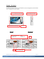
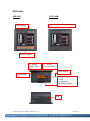
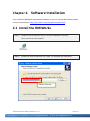
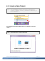
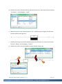
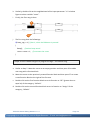
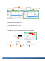
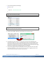
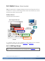
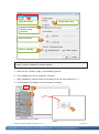
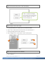
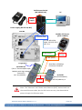
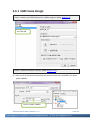
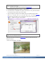
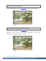
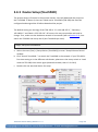
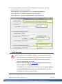
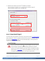
1
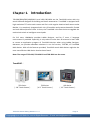
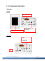
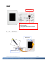
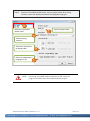
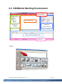
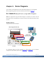
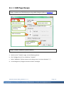
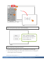
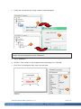
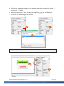
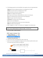
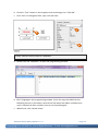
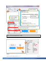
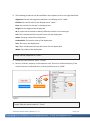
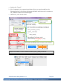
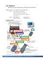
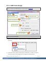
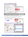
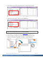
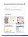
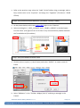
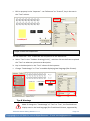
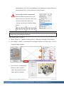
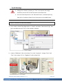
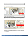
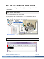
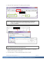
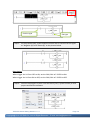
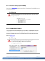
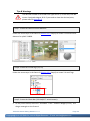
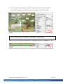
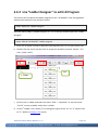
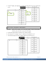
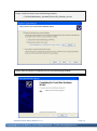
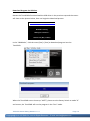
. TouchPAD TPD/VPD Series HMI Devices Getting Started Version: 1.0.1 August, 2011 Usage information for TPD-280 TPD-280U TPD-283 TPD-430 TPD-430-EU VPD-130 VPD-130N TPD/VPD Series Getting Started v.1.0.1 Copyright@ 2011 ICP DAS Co., Ltd. All Rights Reserved. E-mail: [email protected] Page: 1 Warranty All products manufactured by ICP DAS are under warranty regarding defective materials for a period of one year, beginning from the date of delivery to the original purchaser. Warning ICP DAS assumes no liability for any damage resulting from the use of this product.ICP DAS reserves the right to change this manual at any time without notice. The information furnished by ICP DAS is believed to be accurate and reliable. However, no responsibility is assumed by ICP DAS for its use, not for any infringements of patents or other rights of third parties resulting from its use. Copyright Copyright @ 2011 by ICP DAS Co., Ltd. All rights are reserved. Trademark The names used for identification only may be registered trademarks of their respective companies. Contact US If you have any question, please feel free to contact us. We will give you quick response within about 2 workdays. Email: [email protected] [email protected] TPD/VPD Series Getting Started v.1.0.1 Copyright@ 2011 ICP DAS Co., Ltd. All Rights Reserved. E-mail: [email protected] Page: 2 Table of Contents Chapter 1. Introduction ............................................................. 5 1.1 Hardware.............................................................................................6 1.2 Hardware Overview .............................................................................7 Chapter 2. Software Installation............................................... 11 2.1 Install the HMIWorks ......................................................................... 11 2.2 Create a New Project ......................................................................... 12 2.3 HMIWorks Working Environment ...................................................... 14 Chapter 3. Demo Programs ...................................................... 15 3.1 Demo 0 (Beep & Count, using Ladder Designer) ................................. 15 3.1.1 HMI Page Design................................................................................................. 16 3.1.2 Device Setup (TouchPAD) ................................................................................... 25 3.1.3 Download Project ............................................................................................... 25 3.2 Demo 1 (Beep, Timer, Counter).......................................................... 27 3.2.1 HMI Page Design................................................................................................. 27 3.2.2 Device Setup (TouchPAD) ................................................................................... 34 3.2.3 Download Project ............................................................................................... 34 3.3 Demo 2 (Remote I/O: Light, Temperature, Communication Detector)36 3.3.1 HMI Frame Design .............................................................................................. 37 3.3.2 Edit a LD Program using “Ladder Designer” ....................................................... 46 3.3.3 Device Setup (TouchPAD) ................................................................................... 49 3.3.4 Download Project ............................................................................................... 49 3.4 Demo 3 (Multi HMI with ISaGRAF PAC: Light, Temperature, Communication Detector) .................................................... 50 3.4.1 HMI Frame Design .............................................................................................. 52 3.4.2 Use “Ladder Designer” to edit LD Program ........................................................ 57 3.4.3 Device Setup (TouchPAD) ................................................................................... 59 3.4.4 Download Project ............................................................................................... 61 TPD/VPD Series Getting Started v.1.0.1 Copyright@ 2011 ICP DAS Co., Ltd. All Rights Reserved. E-mail: [email protected] Page: 3 Appendix A. Download Information .......................................... 62 Appendix B. Configure the I/O Module ...................................... 63 Appendix C. Create Your Own GUI ............................................. 67 Appendix D. Configure & Program the ISaGRAF PAC .................. 68 Appendix E. Display the Decimal Point ...................................... 71 Appendix F. Use USB to Download Program .............................. 73 TPD/VPD Series Getting Started v.1.0.1 Copyright@ 2011 ICP DAS Co., Ltd. All Rights Reserved. E-mail: [email protected] Page: 4 Chapter 1. Introduction TPD-280/280U/283/430/430-EU and VPD-130/130N are the TouchPAD series with tiny touch HMI and designed for building and home automation. TouchPAD is equipped with high resolution TFT color touch screen and fits in with regular electrical wall-mount outlet. Besides, it is seamlessly integrated with rich I/O modules and presents beautiful, flexible and user-defined picture frame. In short, the TouchPAD is the best choice to upgrade the mechanical switch to intelligent control pads. For PLC users, HMIWorks provides Ladder Designer, and for IT users, C language environment is provided. Especially, it only takes no more than 30 minutes to learn how to create an application program of TouchPAD devices when using Ladder Designer. Moreover, we provide redundant solutions in our PoE version, TPD-283, of TouchPAD HMI devices. With all the features provided, TouchPAD touch HMI devices might be the most cost effective HMI device that has been found. Note: The usage of TPD-430, TPD-430-EU and TPD-280U are the same. TouchPAD: TPD Series (2.8” Touch Screen) TPD Series (4.3” Touch Screen) VPD Series (3.5” Touch Screen) TPD/VPD Series Getting Started v.1.0.1 Copyright@ 2011 ICP DAS Co., Ltd. All Rights Reserved. E-mail: [email protected] Page: 5 1.1 Hardware If you want to know the hardware specifications for various models of TouchPAD, please refer to our website: www.icpdas.com.tw > Product > Solutions > HMI & Touch Monitor > TouchPAD or http://www.icpdas.com.tw/product/solutions/hmi_touch_monitor/touchpad/touchpad_ selection.html TPD/VPD Series Getting Started v.1.0.1 Copyright@ 2011 ICP DAS Co., Ltd. All Rights Reserved. E-mail: [email protected] Page: 6 1.2 Hardware Overview TPD Series TPD-280: Power/GND/RS-485 2.8” TFT LCD with Touch Panel Rotary Switch (0 ~ 9) 0: Run Only 1: Update Only TPD-280U: 0: Run 1: Update OS 9: Update AP USB TPD/VPD Series Getting Started v.1.0.1 Copyright@ 2011 ICP DAS Co., Ltd. All Rights Reserved. E-mail: [email protected] Page: 7 TPD-283: Ethernet (PoE) Rotary Switch (0 ~ 9) 0: Run and Update 1: Force Update (When program damage) 2: Run Only Reset TouchPAD Button Reset Button Open the Top Cover TPD/VPD Series Getting Started v.1.0.1 Copyright@ 2011 ICP DAS Co., Ltd. All Rights Reserved. E-mail: [email protected] Page: 8 TPD-430、TPD-430-EU: The different between TPD-430 and TPD-430-EU is the size of appearance which divided into U.S. gauge and European gauge. 4.3” TFT LCD with Touch Panel Programmable LED Indicator Speaker TPD-430: TPD-430-EU: Rotary Switch (0 ~ 9) 1: Update OS USB Reset Button (Left Side) 0: Run 2: Update AP USB Power/GND/RS-485 TPD/VPD Series Getting Started v.1.0.1 Copyright@ 2011 ICP DAS Co., Ltd. All Rights Reserved. E-mail: [email protected] Page: 9 VPD Series VPD-130: VPD-130N: 3.5” TFT LCD with Touch Panel LED Indicator Rubber Keypad RS-485 Data- Data+ RS-232 TxD RxD GND Reset Button Power/GND Rotary Switch (0 ~ 9) 0: Run 1: Update OS 9: Update Program USB TPD/VPD Series Getting Started v.1.0.1 Copyright@ 2011 ICP DAS Co., Ltd. All Rights Reserved. E-mail: [email protected] Page: 10 Chapter 2. Software Installation First, install the HMIWorks development software in your PC. Please download the latest version at the website: http://ftp.icpdas.com/pub/cd/touchpad/setup/ 2.1 Install the HMIWorks Step 1: Double click the execution file to install the HMIWorks software. (This manual use V2.01 beta5) Step 2: Follow the setup wizard and click “Next” to complete the installation. Default directory TPD/VPD Series Getting Started v.1.0.1 Copyright@ 2011 ICP DAS Co., Ltd. All Rights Reserved. E-mail: [email protected] Page: 11 2.2 Create a New Project Step 1: After the HMIWorks installation, select [ Start ] > [ All Programs ] > [ ICPDAS ] > [ HMIWorks_Standard ] > [ HMIWorks Standard Edition ] to execute the software. (If the Windows Security Warning dialog appears in the Windows 7, please click “Unlock”.) Step 2: Select “New Project” to create a new project. TPD/VPD Series Getting Started v.1.0.1 Copyright@ 2011 ICP DAS Co., Ltd. All Rights Reserved. E-mail: [email protected] Page: 12 Step 3: Select the TouchPAD model name, input a project name & its saving location, select the display orientation and programming type. a. Select the TouchPAD model name b. Input a project name c. Default saving location Select the orientation to display HMI d. Select to program by C language or LD e. NOTE: If a wrong TouchPAD model is selected, it will cause the program mistakes and cannot download the project. TPD/VPD Series Getting Started v.1.0.1 Copyright@ 2011 ICP DAS Co., Ltd. All Rights Reserved. E-mail: [email protected] Page: 13 2.3 HMIWorks Working Environment Function Menu HMI Design area Workspace / Toolbox Properties / Picture libraries Result section (output/errors) Status bar Toolbox: TPD/VPD Series Getting Started v.1.0.1 Copyright@ 2011 ICP DAS Co., Ltd. All Rights Reserved. E-mail: [email protected] Page: 14 Chapter 3. Demo Programs In this chapter, we will guide you to write simple demo programs in C or LD language. Before programming, please install the hardware and the software (Chapter 2). 3.1 Demo 0 (Beep & Count, using Ladder Designer) Demo 0 is programmed using the Ladder Designer to implement one button that will beep when click on it and add one to a counter and reset to zero when the counter comes up to 10. Hardware Devices: Using TPD-280 for demo example 0 Power Supply (DP-665, 24V) USB GND USB/RS-485 Converter (I-7561) Power(+10~30 VDC) Frame Ground RS-485 (Data+) RS-485 (Data-) TPD-280 For information about the driver download of I-7561 module and the hardware configuration of I/O modules, please refer to Appendix A and Appendix B. TPD/VPD Series Getting Started v.1.0.1 Copyright@ 2011 ICP DAS Co., Ltd. All Rights Reserved. E-mail: [email protected] Page: 15 3.1.1 HMI Page Design Step 1: Create a new TPD-280 project using Ladder Designer (refer to Section 2.2). a. Select the device b. Input project name c. Default saving directory HMI orientation d. Select Ladder to program e. Step 2: Create a “BitButton” (picture button). a. Switch to the “Toolbox” page, as the following picture. b. Click “Widget (Ctrl+2)” to unfold the “Toolbox”. c. Select “BitButton” (Move mouse to the design area, the cursor become “+”). d. In the design area, drag the mouse to draw a rectangle. TPD/VPD Series Getting Started v.1.0.1 Copyright@ 2011 ICP DAS Co., Ltd. All Rights Reserved. E-mail: [email protected] Page: 16 a. b. c. d. Step 3: As the previous step, create a “Label” (text display) “Label”, a component of Widget, can be used for the text and control functions; however, the “Text” is for the text display only. Step 4: Create 2 tags, “beep_tag” and “count”. a. As the picture below, right click “Virtual” in the Workspace to create the tags. b. Key in the name of the tag in the “Edit variable” window. Here we use “beep_tag” for the first tag and “count” for the second. TPD/VPD Series Getting Started v.1.0.1 Copyright@ 2011 ICP DAS Co., Ltd. All Rights Reserved. E-mail: [email protected] Page: 17 c. Finally, we can see that the 2 tags created in the Workspace. a. b. c. Step 5: Set up the properties of the “BitButton”. a. Select “BitButton”. b. Click the “Text” column in the Inspector area and change it to “Click Me”. c. Click “Font” to change the font, style, size and color. a. c. b. TPD/VPD Series Getting Started v.1.0.1 Copyright@ 2011 ICP DAS Co., Ltd. All Rights Reserved. E-mail: [email protected] Page: 18 d. Click on the “TagName” property in the Inspector and there shows a little button “…”. Click on the “…” button. e. Select the tag you want. Here we select the tag, “beep_tag”, for the BitButton. f. Finally, we can see the tag we just choose. f. d. e. Step 6: Set up the properties for “Label”. a. Select the Label. b. a. c. TPD/VPD Series Getting Started v.1.0.1 Copyright@ 2011 ICP DAS Co., Ltd. All Rights Reserved. E-mail: [email protected] Page: 19 b. The following properties can be modified in the Inspector area on the right hand side: Alignment: Set the text alignment position in the display box of “Label”. FillColor: Set the fill color for the display box of “Label”. Font: Set the font for the text in the display box. Height: Set the height of the display box. ID: A unique serial number to identify different entities in the same type. Left: The X-coordinate of the top left corner for the display box. Name: The type name of the component. OutlineColor: The outline color of the display box. Text: The text in the display box. Top: The Y-coordinate of the top left corner for the display box. Width: The width of the display box. c. Select “TagName” as “count”. (It is similar to set “TagName” as the above step.) Step 7: Use the Ladder Designer to program the logic – the first rung. a. Click menu [HMI] > [Ladder Designer]. b. Press F2 (or F2 key on the keyboard) to create a new rung. c. Move the cursor (the highlighted rectangle) to the first contact symbol and then press F7 to add a new function block to the right of it. b. c. TPD/VPD Series Getting Started v.1.0.1 Copyright@ 2011 ICP DAS Co., Ltd. All Rights Reserved. E-mail: [email protected] Page: 20 d. Double-click on the function block to set the function to it. Here we set it the function, “increment”, of the category, “math”. e. Move the cursor to the function block of “inc” and then press F7 again to add a new function block to the right of it. f. Double-click on the second function block to set the function to it. Here we set it the function, “Beep”, of the category, “system”. g. Double-click on the contact symbol to select variable “beep_tag”. g. f. TPD/VPD Series Getting Started v.1.0.1 Copyright@ 2011 ICP DAS Co., Ltd. All Rights Reserved. E-mail: [email protected] Page: 21 h. Similarly, double-click on the neighborhood of the input parameter “in” as below figure to select variable “count”. i. Finally, the first rung is done. h. i. j. The first rung does the followings: if( beep_tag == 1 ) //that is, when the BitButton is pressed. { Beep(); //make a beep sound count = count + 1; //increment the count } Step 8: Use the Ladder Designer to program the logic – the second rung. a. Similar to Step 7. Move the cursor to an empty position and then press F6 to add a new rung with a function block. b. Move the cursor to the previously-created function block and then press F7 to create a new function block to the right of the first one. c. Double-click on the first function block to set its function to “GE” (greater than or equal to) of the category, “default”. d. Double-click on the second function block to set its function to “Assign” of the category, “default”. TPD/VPD Series Getting Started v.1.0.1 Copyright@ 2011 ICP DAS Co., Ltd. All Rights Reserved. E-mail: [email protected] Page: 22 b. d. c. e. Set the value of the parameter “in2” of the function “GE” (>=) by double-clicking on the neighborhood of the parameter “in2”. f. To enter a constant to a parameter, click on the tab “Enter Constant” in the “Select variable” variable. Here we enter 10. g. Similarly, set the parameter “in” of the function “Assign” to zero. h. Similarly, select “count” to parameter “in1” of the function “GE” (>=). i. Similarly, select “count” to the parameter “out” of the function “Assign”. f. e. h. i. g. TPD/VPD Series Getting Started v.1.0.1 Copyright@ 2011 ICP DAS Co., Ltd. All Rights Reserved. E-mail: [email protected] Page: 23 j. The second rung does the followings: if( count >= 10 ) { count = 0; //set the count to zero } Step 9: Save and Close (the Ladder). Step 10: Tune the scan time if necessary. a. Click the menu [HMI] > [Refresh Time (I/O Scan)] to set the scan time. b. The default scan time is 100 ms. The scan time is the time interval between two consecutive Ladder scan. That is, TouchPAD executes each rung of the ladder serially from the first rung to the last and after finishing the last rung, it waits until the scan time interval is up (the scan time interval is calculated from the time of the first rung’s execution) to execute from the beginning (the first rung) again. c. The scan time might influence the feeling of sensitivity. If the scan time is too small, touching the BitButton on the screen one time may causes it triggering many times and thus makes the counter increment more than one. TPD/VPD Series Getting Started v.1.0.1 Copyright@ 2011 ICP DAS Co., Ltd. All Rights Reserved. E-mail: [email protected] Page: 24 3.1.2 Device Setup (TouchPAD) Step 1: Click the function menu [ Run ] > [ Setup Device (TouchPAD) ]. Step 2: Select the “COM” port number and click “OK”. In this example, we set “COM3” of PC to use I-7561 (convert USB to RS-485). Please set the connected COM port of your PC. To know the COM number your PC used, please check it from the “Device Manager” of your PC. Note : If the PC’ OS is Windows 7 and there is no COM port options in the “Setup Serial Device” window, please exit the software and right click on the HMIWorks_Standard” icon on the PC desktop to execute the software as an “administrator”. 3.1.3 Download Project After finish the HMI page design, next, download the project to the TouchPAD. Step 1: Turn the Rotary Switch on the back plane of TPD-280 to “1”, and then reset the TouchPAD. Refer to Section 1.2 Hardware Overview. (The TPD-280 screen is dark after reset.) TPD/VPD Series Getting Started v.1.0.1 Copyright@ 2011 ICP DAS Co., Ltd. All Rights Reserved. E-mail: [email protected] Page: 25 Step 2: Select [ Run ] > [ Rendering and Build ] in the HMIWorks menu to compile and make the project. Step 3: Select [ Run ] > [ Download Only ] to download the project. Step 4: After the project downloaded, turn the Rotary Switch of TPD-280 to “0” and reset the TouchPAD. Refer to Section 1.2 Hardware Overview. (The TPD-280 will display the HMI screen after reset.) TPD/VPD Series Getting Started v.1.0.1 Copyright@ 2011 ICP DAS Co., Ltd. All Rights Reserved. E-mail: [email protected] Page: 26 3.2 Demo 1 (Beep, Timer, Counter) Demo 1 is programmed in C language to design one button that will beep when click on it and add one to a counter; and also design another counter that will add one per second and reset to zero when it comes up to 100. Hardware Devices: Using TPD-280 for demo example 1 Power Supply (DP-665, 24V) USB GND USB/RS-485 Converter (I-7561) Power(+10~30 VDC) Frame Ground RS-485 (Data+) RS-485 (Data-) TPD-280 For information about the driver download of I-7561 module and the hardware configuration of I/O modules, please refer to Appendix A and Appendix B. 3.2.1 HMI Page Design Step 1: Create a new TPD-280 project using C language (refer to Section 2.2). TPD/VPD Series Getting Started v.1.0.1 Copyright@ 2011 ICP DAS Co., Ltd. All Rights Reserved. E-mail: [email protected] Page: 27 a. Select the device b. Input project name c. Default saving directory HMI orientation d. Select C language e. Step 2: Create a “BitButton” (picture button). a. Switch to the “Toolbox” page, as the following picture. b. Click “Widget (Ctrl+2)” to unfold the “Toolbox”. c. Select “BitButton” (Move mouse to the design area, the cursor become “+”). d. In the design area, drag the mouse to draw a rectangle. a. b. c. d. TPD/VPD Series Getting Started v.1.0.1 Copyright@ 2011 ICP DAS Co., Ltd. All Rights Reserved. E-mail: [email protected] Page: 28 Step 3: As the previous step, create a “Label” (text display) “Label”, a component of Widget, can be used for the text and control functions; however, the “Text” is for the text display only. Step 4: Create a “Timer” and a “Label”. a. As the picture below, click “System (Ctrl+3)” to unfold the toolbox. b. Select “Timer”. Move mouse to the Frame1 area, the mouse become “+”. c. Click on the design area to create a Timer icon. d. Select “Widget (Ctrl+2)”, create another “Label” as below picture. a. b. c. d. Step 5: Set up the properties of the “BitButton”. a. Select “BitButton”. TPD/VPD Series Getting Started v.1.0.1 Copyright@ 2011 ICP DAS Co., Ltd. All Rights Reserved. E-mail: [email protected] Page: 29 b. Click the “Text” column in the Inspector area and change it to “Click Me”. c. Click “Font” to change the font, style, size and color. c. a. b. Step 6: Edit the control codes for “BitButton”. a. Double click the “BitButton” to open the programming window. b. Edit C language in the programming window. (User can copy the code from the following picture.) In this demo, each click of the button will add 1 and beep once until it cumulate to 100, and then reset to 0 to cumulate again. c. When finish, click “Save & Close”. TPD/VPD Series Getting Started v.1.0.1 Copyright@ 2011 ICP DAS Co., Ltd. All Rights Reserved. E-mail: [email protected] Page: 30 b. Declare variables long cnt1=0; static char str1[32]; c. void BitButton4OnClick(tWidget *pWidget) { hmi_Beep(); Beep function cnt1=cnt1+1; if (cnt1>100) { cnt1=0; } usprintf(str1,"%d",cnt1); LabelTextSet(&LabelWidget5, str1); Convert integer to string for showing on the Label. } This name must be the same as the property “Name + ID” of the Label. Step 7: Set up the properties for “Label”. a. Select a Label ("LabelWidget5" or "LabelWidget7"). b. a. TPD/VPD Series Getting Started v.1.0.1 Copyright@ 2011 ICP DAS Co., Ltd. All Rights Reserved. E-mail: [email protected] Page: 31 b. The following properties can be modified in the Inspector area on the right hand side: Alignment: Set the text alignment position in the display box of “Label”. FillColor: Set the fill color for the display box of “Label”. Font: Set the font for the text in the display box. Height: Set the height of the display box. ID: A unique serial number to identify different entities in the same type. Left: The X-coordinate of the top left corner for the display box. Name: The type name of the component. OutlineColor: The outline color of the display box. Text: The text in the display box. Top: The Y-coordinate of the top left corner for the display box. Width: The width of the display box. Step 8: Set the properties of “Timer”. a. Follow the picture below. Select “Timer6”. b. Set the “Interval” property in the Inspector area. The unit is milliseconds (ms); if the control function is executed every 1 second, please set it as “1000”. a. b. Step 9: Edit the control codes for “Timer”. TPD/VPD Series Getting Started v.1.0.1 Copyright@ 2011 ICP DAS Co., Ltd. All Rights Reserved. E-mail: [email protected] Page: 32 a. Double click “Timer6”. b. Edit C language in the programming window. (User can copy the code from the following picture.) In this demo, the counter will add 1 each time until it cumulate to 100, and then reset to 0 to cumulate again. c. When finish, click “Save & Close”. b. Convert integer to string and display on the Label. long cnt1=0; long auto_cnt1=0; static char str1[32]; Declare variable (auto_cnt1) void Timer6OnExecute(tWidget *pWidget) { auto_cnt1=auto_cnt1+1; if (auto_cnt1>100) { auto_cnt1=0; } usprintf(str1,"%d",auto_cnt1); LabelTextSet(&LabelWidget7, str1); } This name must be the same as “Name + ID” of Label. Step 10: The Demo 1 is done. Please click menu [File] > [Save] to save file. TPD/VPD Series Getting Started v.1.0.1 Copyright@ 2011 ICP DAS Co., Ltd. All Rights Reserved. E-mail: [email protected] Page: 33 3.2.2 Device Setup (TouchPAD) Step 1: Click the function menu [ Run ] > [ Setup Device (TouchPAD) ]. Step 2: Select the “COM” port number and click “OK”. In this example, we set “COM3” of PC to use I-7561 (convert USB to RS-485). Please set the connected COM port of your PC. To know the COM number your PC used, please check it from the “Device Manager” of your PC. Note : If the PC’ OS is Windows 7 and there is no COM port options in the “Setup Serial Device” window, please exit the software and right click on the HMIWorks_Standard” icon on the PC desktop to execute the software as an “administrator”. 3.2.3 Download Project After finish the HMI page design, next, download the project to the TouchPAD. Step 1: Turn the Rotary Switch on the back plane of TPD-280 to “1”, and then reset the TouchPAD. Refer to Section 1.2 Hardware Overview. (The TPD-280 screen is dark after reset.) TPD/VPD Series Getting Started v.1.0.1 Copyright@ 2011 ICP DAS Co., Ltd. All Rights Reserved. E-mail: [email protected] Page: 34 Step 2: Select [ Run ] > [ Rendering and Build ] in the HMIWorks menu to compile and make the project. Step 3: Select [ Run ] > [ Download Only ] to download the project. Step 4: After the project downloaded, turn the Rotary Switch of TPD-280 to “0” and reset the TouchPAD. Refer to Section 1.2 Hardware Overview. (The TPD-280 will display the HMI screen after reset.) TPD/VPD Series Getting Started v.1.0.1 Copyright@ 2011 ICP DAS Co., Ltd. All Rights Reserved. E-mail: [email protected] Page: 35 3.3 Demo 2 (Remote I/O: Light, Temperature, Communication Detector) Demo 2 is designed in LD language to create two HMI frames: Frame1: Light display/control (DI/DO) x 8, Temperature display (I-7018Z ch0) x 1 Communication detector (I-7055, I-7018Z) x 1 Frame switch x 1 Frame2: Scene picture x 1 Control button x 1 Light control (DO) x 2 Frame switch x 1 Hardware Devices: Using TPD-280, I-7055, I-7018Z for demo 2 Power Supply (DP-665, 24V) GND USB/RS-485 Converter (I-7561) Power (+10~30 VDC) USB Frame Ground RS-485 (Data+) RS-485 (Data-) TPD-280 RS-485 (Data+) Baud Rate: 19200 bps Checksum: Disabled RS-485 (Data-) I-7055D (8 DI, 8 DO Module) NET-ID (Address): 1 K-Type wire Power I-7018Z-G/S (10-ch. Thermocouple Input Module with High Voltage Protection) NET-ID (Address): 2 TPD/VPD Series Getting Started v.1.0.1 Copyright@ 2011 ICP DAS Co., Ltd. All Rights Reserved. E-mail: [email protected] Page: 36 3.3.1 HMI Frame Design Step 1: Create a new TPD-280 project using LD (refer to Section 2.2). a. b. Select the device Input project name c. Default saving directory HMI orientation d. Select LD program e. Step 2: Set up the connection. a. Right click the [Connection] > [New Connection] of “Workspace” to set up the connection. b. In this demo, select “UART” Protocol and set “Baud Rate” as “19200”, then give a connection name or click “Assign name” to assign one name by system. TPD/VPD Series Getting Started v.1.0.1 Copyright@ 2011 ICP DAS Co., Ltd. All Rights Reserved. E-mail: [email protected] Page: 37 Step 3: Set up I/O device tags. (This demo: I-7055D, I-7018Z) a. Right click the “Device” of “Workspace”, then “New Device”. b. Select “I-7000” in “Device Series” and the created “UART” in “Connection”. c. Click “Select” button to select the I/O module. (This demo: I-7055) d. Input the address number of I-7055 in “Net ID”. (This demo: Net ID= 1, refer to Appendix B) a. b. d. C. TPD/VPD Series Getting Started v.1.0.1 Copyright@ 2011 ICP DAS Co., Ltd. All Rights Reserved. E-mail: [email protected] Page: 38 e. Give a device name or click “Assign device name” to assign name by system. f. Repeat above steps to add I-7018Z I/O module (Net ID = 2)。 Step 4: Create the light display/control. (This demo: 8 DI/DOs) a. Click “Libraries” on the right side, select the graphic (GUI) you want to use. b. Select and drag the I/O tag want to connect from the left side into the frame. c. Repeat the steps above to drag DI0 ~7 and DO0 ~7 into the HMI frame. a. c. b. TPD/VPD Series Getting Started v.1.0.1 Copyright@ 2011 ICP DAS Co., Ltd. All Rights Reserved. E-mail: [email protected] Page: 39 Step 5: Create the temperature display. (This demo: I-7018Z ch0) For the temperature value, you can use the height or width of “Slider” to display by rectangle size, or choose the “Label” to display by numeric. a. As the following picture, unfold the Toolbox-Widget (Ctrl+2), select “Slider” and drag a rectangle in the Fram1. b. In the “Inspector” of property, you can change the background fill color (“BackgroundFillColor”), fill color (“FillColor”), outline color (“OutlineColor”), or set “Vertical” to “True” to show the value from bottom to up (“False” will show the value from left to right.). c. Change “Max” and “Min” to fit the maximum and minimum values. d. Select “TagName” to enter “Select variable” window, click “Scope” to set the I/O Tag (This demo: I-7018Z AI ch0). b. a. c. d. e. TPD/VPD Series Getting Started v.1.0.1 Copyright@ 2011 ICP DAS Co., Ltd. All Rights Reserved. E-mail: [email protected] Page: 40 e. Refer to the previous step, select the “Label” of the Toolbox, drag a rectangle, edit its font, outline color in the “Inspector” and assign the “TagName” (This demo: I-7018Z AI ch0). Step 6: Set up communication detectors. (This demo: I-7055D, I-7018Z) a. As the picture below, select two graphic (GUI) lights in the “Libraries”. b. Select and drag the “I_7055_1_ERROR” and “I_7018Z_2_ERROR” in the Workspace into the frame. (The light will turn on if there is any communication problem between the TouchPAD and I/O modules.) a. b. Step 7: Set up the button to switch frame. a. Click the menu [ Layout ] > [ New Frame ] and select “SoftPLC” to create a new LD frame. a. b. b. Select “BitButton” in the “Toolbox- Widget (Ctrl+2)” and drag a rectangle in the Frame1. TPD/VPD Series Getting Started v.1.0.1 Copyright@ 2011 ICP DAS Co., Ltd. All Rights Reserved. E-mail: [email protected] Page: 41 c. Edit its property in the “Inspector” : set “Reference” as “Frame2”, key in the text in the “Text” column. c. Step 8: Create Text components. You can create the “Text” to describe the component on the HMI frames. a. Select “Text” in the “Toolbox- Drawing (Ctrl+1)”, and then click on the frame to placed the "Text" on wherever you want to description. b. Key in the description in the “Text” column of the Inspector. c. Change “TextAsImage” to “True” to enable displaying local language (like Chinese). Tips & Warnings Note: If change the “TextAsImage” of “Text” to “True”, the TouchPAD can display texts in the local language (like Tranditional Chinese, supported by TPD/VPD Series Getting Started v.1.0.1 Copyright@ 2011 ICP DAS Co., Ltd. All Rights Reserved. E-mail: [email protected] Page: 42 MS Windows). The “Text” and “BitButton” are displayed in image mode that converted from text, so they take more memory space. How to align multiple components? Select the HMI components by circle them in mouse or press the “Shift” key to click multiple ones, then click “Layout” on the menu to select a align option. Step 9: Set up the background picture. First, switch to the “Frame2”. a. Select “Picture” in “Toolbox- Drawing (Ctrl+1)” and drag a rectangle on the Frame2. b. Edit “Height”, “Width” in the Inspector to change the picture size. Edit “Left”, “Top” to change the align position. b. a. c. c. Click “Picture” or double click the box on the Frame2 to “Load” the picture from the “Select picture” window. TPD/VPD Series Getting Started v.1.0.1 Copyright@ 2011 ICP DAS Co., Ltd. All Rights Reserved. E-mail: [email protected] Page: 43 Tips & Warnings a. Change the “HiColor” property to “True” can improve the image resolution, but the file size will increase at the same time. b. You can draw the picture in the “Microsoft Paint”, use Select (Ctrl+A), Copy (Ctrl+C) and then Paste (Ctrl+V) the picture to the HMI frame. Step 10: Create the Virtual control button. a. First, create a Virtual Tag. Right click on “Virtual” and select “New Virtual Tag”, then give a variable name (ex: V1) in “Edit variable” window. b. Create a “BitButton” refer to the Step 7-b. In the “Inspector”, change “Font” and “Text”, then assign “V1” to “TagName” (refer to Step 5-d). TPD/VPD Series Getting Started v.1.0.1 Copyright@ 2011 ICP DAS Co., Ltd. All Rights Reserved. E-mail: [email protected] Page: 44 Step 11: Create the light displays. Refer to the steps of the Step 4, create 2 light displays and assign the “I_7055_1_DO0” and “I_7055_1_DO1” to the “TagName”. Step 12: Create a frame switch for Frame2. Refer to the Step 7, create a frame switch. You can copy and paste the frame switch from Frame1, then change the “Reference” to “Frame1” and edit the “Text” to display. Now, the frame design is done. Next chapter will show you how to use “Ladder Designer” to edit a LD program. TPD/VPD Series Getting Started v.1.0.1 Copyright@ 2011 ICP DAS Co., Ltd. All Rights Reserved. E-mail: [email protected] Page: 45 3.3.2 Edit a LD Program using “Ladder Designer” In this demo, we use the “Light Control” button (V1) to control 2 lights (DO0 and DO1 of I-7055D module). Step 1: Open the “Ladder Designer”. a. In the Frame2, click the “Light Control” button. b. Press the menu [HMI] > [Ladder Designer] or “F4” of the key board to open the “Ladder Designer”. Step 2: Edit the LD program. a. Click “F2” to insert a “Contact”. TPD/VPD Series Getting Started v.1.0.1 Copyright@ 2011 ICP DAS Co., Ltd. All Rights Reserved. E-mail: [email protected] Page: 46 b. Select the “Coil” and click the “F5” to add a new Coil as below. Normal open switch Coil Step 3: Assign variables. Double click the “normal open switch”, and select the variable “V1”; repeat the same step to assign variables to the coils. (I_7055_1_DO0/DO1) Step 4: Change the type for the switch and the coils. a. Select the “V1 Switch” and click the “Space [T]” (or the “Space” or “P” of the key board) to switch the type to “Positive (P)”. b. The similar way (or “S” key) to switch the type of Coils to “Set (S)”. TPD/VPD Series Getting Started v.1.0.1 Copyright@ 2011 ICP DAS Co., Ltd. All Rights Reserved. E-mail: [email protected] Page: 47 Positive type Set type Step 5: As the previous step, create another Contact with 2 Coils but set the types as “Negative (N)” and “Reset (R)” as the picture below. Description: When trigger the V1 from OFF to ON, set the DO0, DO1 of I-7055D to ON. When trigger the V1 from ON to OFF, set the DO0, DO1 of I-7055D to OFF. Step 6: Now the LD program is done. Click the menu [File] > [Save & Close] to save project and exit the software. TPD/VPD Series Getting Started v.1.0.1 Copyright@ 2011 ICP DAS Co., Ltd. All Rights Reserved. E-mail: [email protected] Page: 48 3.3.3 Device Setup (TouchPAD) Please refer to Section 3.1.2, select the menu [Run] > [Setup Device (TouchPAD)] to set up the download interface. Tips & Warnings To know the COM number your PC used, please check it from the “Device Manager” of your PC. 3.3.4 Download Project Turn the Rotary Switch on the backplane of the TPD-280 to 1 (Update Mode) and reset the TPD-280, then select the menu [Run] > [Run] to compile, build and download the project to TouchPAD. When finish, turn the Rotary Switch to 0 (Run Mode) and restart. (Refer to Section 3.1.3) Tips & Warnings How to speed up the response time of the components? a. Select the menu [HMI] > [Refresh Time (I/O Scan)] b. Change the Refresh Time TPD/VPD Series Getting Started v.1.0.1 Copyright@ 2011 ICP DAS Co., Ltd. All Rights Reserved. E-mail: [email protected] Page: 49 3.4 Demo 3 (Multi HMI with ISaGRAF PAC: Light, Temperature, Communication Detector) We have learned the I/O connection, component creation and HMI Ladder Designer in the Demo 2. We will introduce Demo 3 briefly. In Demo 3, there are 2 TPD-283 linking to an ISaGRAF PAC (µPAC-7186EG, as a Modbus TCP Server) to read/write I/O modules (M-7055D, M-7018Z) which Modbus Tags are configured by ISaGRAF program. Frame1: Light display/control (M-7055D-DI/DO) x 8 Temperature display (M-7018Z ch0) x 1 Communication detector (µPAC-7186EG) x 1 Control button x 2 Tips & Warnings Note: When using DCON Utility to configure the M-7018Z that uses Modbus RTU of RS-485 Port to connect with the TouchPAD, please set the “Dataformat” as "Engineering" (“Protocol” as Modbus RTU) for the M-7018Z. Note: If you use the later version – HMIWorks v2.02 or later, please set the “Dataformat” as “2’s complement”. Refer to Appendix A and Appendix B to get more information about the driver download of the converter I-7561 and the configuration of the digit/analog I/O modules. Refer to Appendix D to get more information about the ISaGRAF PAC (µPAC-7186EG) and the ISaGRAF programs. Hardware Devices : Using TPD-283 (Web type x2), µPAC-7186EG, M-7055D, M-7018Z for Demo 3 TPD/VPD Series Getting Started v.1.0.1 Copyright@ 2011 ICP DAS Co., Ltd. All Rights Reserved. E-mail: [email protected] Page: 50 PoE Ethernet Switch (NS-205PSE-24V) Power Supply PC Ethernet Power Supply (KA-52F-48, 48V) TPD-283 Modbus TCP Server (µPAC-7186EG) 乙太網路供電 Ethernet (PoE) IP: 192.168.1.204 Mask: 255.255.255.0 NET-ID: 1 RS-485 (Data+) Power RS-485 (Data-) K-Type wire Baud Rate: 19200 bps Checksum: Disabled M-7018Z-G/S (10-ch. Thermocouple Input Module with High Voltage Protection) M-7055D (8 DI, 8 DO Module) NET-ID (Address): 2 Power NET-ID (Address): 1 Note : The “Ethernet” and “Power-over-Ethernet (PoE)” devices both use the nomal Ethernet cable, but the PoE series can carry the data and the power through the Ethernet cable. TPD/VPD Series Getting Started v.1.0.1 Copyright@ 2011 ICP DAS Co., Ltd. All Rights Reserved. E-mail: [email protected] Page: 51 3.4.1 HMI Frame Design Step 1: Create a new TPD-283 project in Ladder program. (Refer Section 2.2) Use TPD-283 Step 2: Create a connection (TCP/IP). (Refer Section 3.2.1) IP : Insert the IP of the device (controller) that connects with the TouchPAD (This demo: µPAC-7186EG). The IP of µPAC-7186EG TPD/VPD Series Getting Started v.1.0.1 Copyright@ 2011 ICP DAS Co., Ltd. All Rights Reserved. E-mail: [email protected] Page: 52 Step 3: Configure the I/O Tags. (Device: µPAC-7186EG, refer to the Step 3 of Section 3.2.1) a. In the Workspace, right click on “Device” > “New Device”. b. Set “Device Series” to “Modbus TCP” and set “Connection” to “TCP_204” that created in the previous step, and then press “Edit” button. c. We pre-configure the address of the Modbus Tags in the ISaGRAF program (DO0 ~ DO7 = 21 ~ 28 ; DI0 ~ DI7 = 01 ~ 08 ; AI0 ~ AI9 = 101 ~ 110, refer to Appendix D), please assign the address to the “StartAddress” and “Count” column of the “Import…” window. Then, give a “Device Name”. b. c. Step 4: Set up the background picture. Follow the same steps in the Demo 2 (Section 3.2.1 Step 9) to create and set up the background picture. * Picture size: 320 (Width) x 240 (Hight) TPD/VPD Series Getting Started v.1.0.1 Copyright@ 2011 ICP DAS Co., Ltd. All Rights Reserved. E-mail: [email protected] Page: 53 Step 5: Create the light display/control. Follow the same steps in the Demo 2 (Section 3.2.1 Step 4) to create 8 DI/DO lights. Step 6: Create the temperature display. (This demo: AI0) Follow the same steps in the Demo 2 (Section 3.2.1 Step 5) to create a “Slider” (Set the Max=1000, due to the K-type will show 3 digits for the Modbus I/O.) and a “Label” (“TagName”= AI0) to display the temperature value. TPD/VPD Series Getting Started v.1.0.1 Copyright@ 2011 ICP DAS Co., Ltd. All Rights Reserved. E-mail: [email protected] Page: 54 Tips & Warnings The decimal number of M-7018Z for K-type will be 1, in this case, the 269 means Centigrade degree 26.9. If you need to show the decimal point, please refer to Appendix E. Step 7: Create the communication detector. Follow the same steps in the Demo 2 (Section 3.2.1 Step 6) to create a communication detector for µPAC-7186EG. Step 8: Create the Virtual Tags (V1, V2) Follow the same steps in the Demo 2 (Section 3.2.1 Step 6) to create 2 Virtual Tags. Step 9: Create the Check Box (“All ON/OFF” switch button). a. As the picture below, select the “CheckBox” in the “Toolbox- Widget (Ctrl+2)” and drag a rectangle on the Frame1. TPD/VPD Series Getting Started v.1.0.1 Copyright@ 2011 ICP DAS Co., Ltd. All Rights Reserved. E-mail: [email protected] Page: 55 b. In the Inspector, set “TagName” as “V1” and change color or font by yourself. (The Ladder program for this demo will be introduced in the next section.) Step 10: Create another Check Box (“Saving Mode” switch button). Follow the previous step to create another “CheckBox” and set its “TagName” as “V2”. TPD/VPD Series Getting Started v.1.0.1 Copyright@ 2011 ICP DAS Co., Ltd. All Rights Reserved. E-mail: [email protected] Page: 56 3.4.2 Use “Ladder Designer” to edit LD Program This section will introduce the Ladder program for the “All ON/OFF” and “Saving Mode” switches that created in the previous section. Step 1: Open the “Ladder Designer”. Press the menu [HMI] > [Ladder Designer] or “F4” of the key board to open the “Ladder Designer”. Step 2: Edit the “All ON/OFF” Ladder program. a. Click “F2” to insert a Contact. Select the Coil and then click “F5” to add 7 more Coils. b. Double click the switch and the Coils to assign the variables as below. (Switch: “V1”, Coils: “DO0 ~ DO7”) Coil 1st Ladder c. Click on the 1st Ladder and select the menu “Edit” > “Duplicate” or use key board “Ctrl+D” to copy a Ladder under the 1st Ladder. d. In the 1st Ladder, click “Space [T]” to change the types of the “V1” to “P” and the Coil to “S”. (Refer to Section 3.2.2 step 4) TPD/VPD Series Getting Started v.1.0.1 Copyright@ 2011 ICP DAS Co., Ltd. All Rights Reserved. E-mail: [email protected] Page: 57 e. In the 2nd Ladder, click “Space [T]” to change the types of the “V1” to “N” and the Coil to “R”. nd 2 Ladder 1st Ladder Step 3: Edit the “Saving Mode” Ladder program. Description: When click this button, turn on the lights of DO5~7 and turn off the lights of DO0~4, then click the 2nd time, turn off all lights. a. As the same steps of Step 2, create the “V2” Switch and Coils. b. Click “Space [T]” to change “V2” to “P”, DO0~4 to “R” and DO5~7 to “S”. c. Use the same steps to set the 4th Ladder: Switch to “N” and Coil to “R”. TPD/VPD Series Getting Started v.1.0.1 Copyright@ 2011 ICP DAS Co., Ltd. All Rights Reserved. E-mail: [email protected] Page: 58 3.4.3 Device Setup (TouchPAD) The project design is finished in the previous section, here will download the project to the TouchPAD. In Demo 3, there are 2 Web series TouchPAD (TPD-283) that must be configured and assigned the IP before download the project. The default setting (on the bag) of the TPD-283 is “IP = 192.168.255.1”, “Gateway = 192.168.0.1” and “Mask = 255.255.0.0”. Of course, this may not suitable and need to change. First, make sure the hardware network is connected (refer to Section 3.3), then search the TPD-283 and set up the IP (one TouchPAD per time). Step 1: Set up the TouchPAD IP a. Select the menu [Run] > [Setup Device (TouchPAD)] to enter “Setup Ethernet Device” window. b. Click “Search TouchPAD…” to search the TouchPAD in the network. If your TPD-283 is first time setting or in the different sub domain, please turn the rotary switch to 1 and reset the TPD-283, then search again (about 40 seconds, then IP = 0.0.0.0) c. Double click the searched device for setup. a. b. c. TPD/VPD Series Getting Started v.1.0.1 Copyright@ 2011 ICP DAS Co., Ltd. All Rights Reserved. E-mail: [email protected] Page: 59 d. Use the MAC address on the back plane of TPD-283 to identify the TPD-283. Set up the device as the picture below: “Host IP Address” (PC): IP address of the PC installed the HMIWorks “Device IP address” (middle): IP address for the TouchPAD “Device IP address” (down): IP address used for downloading only The IP below must in the same sub domain. IP of PC IP of TPD-283 IP for downloading only Tips & Warnings Note: If set IP of the TouchPAD as “DHCP”, it needs to wait a while for DHCP assigning IP to TouchPAD. The IP setting is saved in the project not in the TouchPAD, so the IP of TPD-283 will not work until the project is downloaded successfully. ** After this step, please go to next section to download project first. Then set up the 2nd TouchPAD. The HMIWorks can configure one TouchPAD each time. When replace a new TouchPAD (Ethernet version), user must execute "Setup Device (TouchPAD)" to search TouchPAD again. TPD/VPD Series Getting Started v.1.0.1 Copyright@ 2011 ICP DAS Co., Ltd. All Rights Reserved. E-mail: [email protected] Page: 60 e. Follow the same steps to set up the 2nd TPD-283. For example: “Device IP address” (middle): set as “192.168.1.203” and select “Static IP” “Device IP address” (down): set as “192.168.1.205” 3.4.4 Download Project The rotary switch has turned to 1 and restart in the previous section “3.3.3 Device Setup”, please select [Run] > [Run] to compile and download the project to TouchPAD. (Refer to the step 2~3 of Section 3.1.3. When first time download project, it will stay about 20 seconds and then begin to download.) Tips & Warnings Note: The rotary switch of TPD-283 is turned to Mode 1 only when the first time IP setting or the project download failing, beside those situations, please turn the switch to Mode 0 and restart. Before download the project, please execute “Device Setup” and click the HMIWorks menu [Run] > [Run] to compile & download the project, it will restart automatically. TPD/VPD Series Getting Started v.1.0.1 Copyright@ 2011 ICP DAS Co., Ltd. All Rights Reserved. E-mail: [email protected] Page: 61 Appendix A. Download Information This manual is only a brief introduction for TouchPAD functions. Please go to the following websites for more detail information about TouchPAD series. User Manual: http://ftp.icpdas.com/pub/cd/touchpad/document/english/ Products Website: http://www.icpdas.com.tw/product/solutions/hmi_touch_monitor/touchpad/tpd-280.html http://www.icpdas.com.tw/product/solutions/hmi_touch_monitor/touchpad/tpd-430.html http://www.icpdas.com.tw/product/solutions/hmi_touch_monitor/touchpad/vpd-130.html Products Data Sheets: http://ftp.icpdas.com/pub/cd/touchpad/document/english/data_sheet/tpd-280(u)_tpd-283( en).pdf http://ftp.icpdas.com/pub/cd/touchpad/document/english/data_sheet/tpd-430_tpd-430-eu( en).pdf http://ftp.icpdas.com/pub/cd/touchpad/document/english/data_sheet/vpd-130_vpd130n(en ).pdf Download I-7561 (USB to RS-485 converter) Driver: ftp://ftp.icpdas.com/pub/cd/8000cd/napdos/7000/756x/ I-7000 I/O Modules (Support DCON Protocol): http://www.icpdas.com/products/Remote_IO/i-7000/i-7000_list.htm M-7000 I/O Modules (Support Modbus RTU & DCON Protocols): http://www.icpdas.com/products/Remote_IO/m-7000/m-7000_list.htm ISaGRAF Website: http://www.icpdas.com/products/PAC/i-8000/isagraf.htm TPD/VPD Series Getting Started v.1.0.1 Copyright@ 2011 ICP DAS Co., Ltd. All Rights Reserved. E-mail: [email protected] Page: 62 Appendix B. Configure the I/O Module This appendix will show you how to use DCON Utility to configure the Address, Net ID, Baud rate and Data format of the I/O module. Please download the DCON Utility and its user manual at the website below: ftp://ftp.icpdas.com/pub/cd/8000cd/napdos/driver/dcon_utility/ Hardware Wiring I-7561 (USB/RS-485 Converter) PC Power Supply (DP-665, 24V) USB Power Baud Rate: 19200 Checksum: Disabled (+V, GND) RS-485 (Data+, Data-) I-7055D (8 DI, 8 DO Module) NET-ID (Address): 1 Note: Each time set up one module only. I-7018Z-G/S (10-ch Thermocouple Input Module with High Voltage Protection) NET-ID (Address): 2 RS-485 (Data+, Data-) Power Software Installation Double click the installation software icon and press “Next” to complete the installation. TPD/VPD Series Getting Started v.1.0.1 Copyright@ 2011 ICP DAS Co., Ltd. All Rights Reserved. E-mail: [email protected] Page: 63 I/O Configuration I-7055D: a. First, push the switch on the back case of the I-7055D to “Init” mode, and reset I-7055D. b. Run the “DCON Utility” from the icon on the desktop or the Start menu “Start” > “All Programs” > “ICPDAS” > “DCON_Utility” > “DCON_Utility”. c. Click menu “COM Port” to set up the conditions, and click “Start Search”. COM Port of PC Select Baud Rate Select Protocol d. In the I-7055D initial mode, click “7055D” to enter the configuration window. TPD/VPD Series Getting Started v.1.0.1 Copyright@ 2011 ICP DAS Co., Ltd. All Rights Reserved. E-mail: [email protected] Page: 64 e. Set Address = 1, Baud rate=19200, press “Setting”, and then the following prompt message will show up. Please click “OK”. f. Switch the I-7055 to the “Normal” mode and reset I-7055. Then, search module again to confirm the configuration. M-7055D: The setting is similar to I-7055D, but set “Protocol” as “Modbus RTU”. I-7018Z: Refer to the previous steps to configure this module. (As the picture below) Configuration Setting: Address = 2, Baud rate = 19200, Data format = Engineering Channel Enable/Disable Setting: This demo uses one channel only, so set the CH0 to “T/C K-type”. TPD/VPD Series Getting Started v.1.0.1 Copyright@ 2011 ICP DAS Co., Ltd. All Rights Reserved. E-mail: [email protected] Page: 65 Tips & Warnings Note: “T/C ?-type”, with the wire opening detection feature, cannot be selected when the channel is not using. As the picture below, if the yellow part shows “+9999.900”, that means the setting of “Input Range” is wrong, or the channel is not using but set as “T/C ?-type”. And note that every channel must be checked. M-7018Z: The setting is similar to I-7018Z, but set “Protocol” as “Modbus RTU”. Note: If the RS-485 Port of the TouchPAD uses Modbus RTU protocol to connect M-7018Z, the M-7018Z must be set to "Engineering" (Modbus RTU). Note: If you use the later version – HMIWorks v2.02 or later, please set the “Dataformat” as “2’s complement”. TPD/VPD Series Getting Started v.1.0.1 Copyright@ 2011 ICP DAS Co., Ltd. All Rights Reserved. E-mail: [email protected] Page: 66 Appendix C. Create Your Own GUI The HMIWorks Libraries provides many pictures and icons of GUI (Graphical User Interface), and user can also create their own GUIs. a. First, in the MS “Paint”, open the picture file, then mouse click tool box to select all (or key board Ctrl+A) and copy (or key board Ctrl+C) the picture. b. Paste (or key board Ctrl+V) the picture to the HMI frame of HMIWorks, then mouse right click on the picture to select “Add to library…” and enter a name, such as “L04_0”. (The light has two status: 0 means OFF, 1 means ON) c. Follow the same steps to create another picture (L04_1). TPD/VPD Series Getting Started v.1.0.1 Copyright@ 2011 ICP DAS Co., Ltd. All Rights Reserved. E-mail: [email protected] Page: 67 Appendix D. Configure & Program the ISaGRAF PAC This chapter introduces the ISaGRAF program and ISaGRAF PAC used with TouchPAD in the Demo 3 (Section 3.3). ISaGRAF PAC Configuration: The µPAC-7186EG setting in the Demo 3: COM2: Master Baud rate: 19200 IP: 192.168.1.204 Mask: 255.255.255.0 Refer to µPAC-7186EG getting started (Section 3.7 & 3.8) for the setting steps: http://www.icpdas.com/products/PAC/i-8000/getting_started_manual.htm ISaGRAF Variables: Variable Name R7055_DO01 ~ 08 R7055_DI01 ~ 08 R_7018Z01 ~ 10 Address (Hex > Decimal) 0015 ~ 001C 21 ~ 28 0001 ~ 0008 1 ~ 8 0065 ~ 006E 101 ~ 110 Description M-7055D - DO0 ~ 7 M-7055D - DOI ~ 7 M-7018Z - AI0 ~ 9 TPD/VPD Series Getting Started v.1.0.1 Copyright@ 2011 ICP DAS Co., Ltd. All Rights Reserved. E-mail: [email protected] Page: 68 ISaGRAF Program Description: Read 8 Booleans from the Modbus device: ID =1 Return: Read from Modbus 0 OK: True Fail: False Format: bit Convert 1 Word (Signed 16-bit) to 16 Booleans: TPD/VPD Series Getting Started v.1.0.1 Copyright@ 2011 ICP DAS Co., Ltd. All Rights Reserved. E-mail: [email protected] Page: 69 Write 8 Booleans to the Modbus device: ID =1 Read from Modbus 0 開始讀取 Return: OK: True Fail: False Read 10 Words (Signed 16-bit) from the Modbus device: ID =2 Return: Read from Modbus 0 OK: True Fail: False Format: Word TPD/VPD Series Getting Started v.1.0.1 Copyright@ 2011 ICP DAS Co., Ltd. All Rights Reserved. E-mail: [email protected] Page: 70 Appendix E. Display the Decimal Point The numbers in the “Ladder Designer” are displayed in integer without decimal digit. In some case, you may need to calculate or display the decimal. This appendix introduces how to display the decimal point for the thermocouple input modules, I-7018Z (DCON protocol) and M-7018Z (Modbus protocol). I-7018Z Module The “Ladder Designer” displays the received value only the integer part, ignore the decimal part (ex. 26.500 26). But you can display the decimal, such as “26.5”, by changing the “IO.hsf” file of the module. The “IO.hsf” of I-7018Z is in the directory: C:\ICPDAS\HMIWorks_Standard\bin\Modules\I-7000\I-7018Z . Change it as below: Add one line: v_ai[0] = v_ai[0] * 10; so, AI0 value = “265” now. Then, in HMIWorks, set the “DecimalDigits” of “Lable” as 1 to display one decimal digit (26.5). Besides, the AIO value is changed from 26 to 265 now, the “Max” property must be changed to 1000 also if you use the Slider. Remember compile the project and download to the TouchPAD again. TPD/VPD Series Getting Started v.1.0.1 Copyright@ 2011 ICP DAS Co., Ltd. All Rights Reserved. E-mail: [email protected] Page: 71 M-7018Z Module Please refer to the product website to check out the temperature input range and refer to the Section “3.5 Engineering Data Format Table” of the M-7018Z module manual to know the maximum decimal digits for every input type. The Modbus protocol uses 2 bytes to access the data value, so the range value is –32768 ~ +32767. As the table below, when the input range enlarges 10n times, “n” is the decimal digit of the display value. For example of K-Type, if the input value is 26.500, the display value will be 265 (enlarge 101 times). Input Type J K T E R S B N C L M L (DIN43710) Input Range -210 ~ +760 -270 ~ +1372 -270 ~ +400 -270 ~ +1000 0 ~ +1768 0 ~ +1768 0 ~ +1820 -270 ~ +1300 0 ~ 2320 -200 ~ +800 -200 ~ +100 -200 ~ +900 Display Range -2100 ~ +7600 -2700 ~ +13720 -2700 ~ +4000 -2700 ~ +10000 0 ~ +17680 0 ~ +17680 0 ~ +18200 -2700 ~ +13000 0 ~ 23200 -2000 ~ +8000 -20000 ~ +10000 -2000 ~ +9000 Max. Decimal Digits 1 1 1 1 1 1 1 1 1 2 1 1 Therefore, the temperature “265” displayed on the TouchPAD actually is “26.5”. You need to change the “DecimalDigits” of the “Label” in the HMIWorks to 1, then compile / download the project to the TouchPAD again, and then the TouchPAD can display the decimal. TPD/VPD Series Getting Started v.1.0.1 Copyright@ 2011 ICP DAS Co., Ltd. All Rights Reserved. E-mail: [email protected] Page: 72 Appendix F. Use USB to Download Program TPD-280U/430/430-EU and VPD-130/130N both have a USB Port. After completing the HMIWorks project, without having to process the menu [Run] > [Setup Device], the user only needs to download program to the TouchPAD via USB port. (The feature is not yet support Windows 7, 64 bit) Install the TouchPAD USB Driver Step 1: Turn the Rotary Switch of TouchPAD to the mode “9”. First, you will see the “Waiting for connection...” screen on the TouchPAD, please connect the USB cable of TouchPAD to the PC. VPD-130 MiniOS8 is running. Waiting for connection… Version 1.01 (May 11 2011) Step 2: In the auto-run window of “Hardware Update Wizard”, do not connect to “Windows Update” to search, please select “No, not this time”. TPD/VPD Series Getting Started v.1.0.1 Copyright@ 2011 ICP DAS Co., Ltd. All Rights Reserved. E-mail: [email protected] Page: 73 Tips & Warnings Note: The PC with different OS may use the different installation steps. If your PC does not pop up the window of “Hardware Update Wizard”, please execute the “Device Manager” in “Hardware” of “My Computer” to install the driver. Windows XP: Windows 7 (32 bit): Step 3: Select “Install from a list…. (Advanced)”. TPD/VPD Series Getting Started v.1.0.1 Copyright@ 2011 ICP DAS Co., Ltd. All Rights Reserved. E-mail: [email protected] Page: 74 Step 4: Install the driver from the following location: C:\ICPDAS\HMIWorks_Standard\Tools\USB_windows_drivers Step 5: After the driver is installed, you can see the following window. TPD/VPD Series Getting Started v.1.0.1 Copyright@ 2011 ICP DAS Co., Ltd. All Rights Reserved. E-mail: [email protected] Page: 75 Download Program via USB Port Restart the TouchPAD after download the USB driver in the previous step and the screen will show as the picture below, then can begin the download process. VPD-130 MiniOS8 is running. Waiting for connection… Version 1.01 (May 11 2011) In the “HMIWorks”, click the menu [Run] > [Run] to download program into the TouchPAD. When the TouchPAD screen shows up “100%”, please turn the Rotary Switch to mode “0” and restart, the TouchPAD will run the program in the “Run” mode. TPD/VPD Series Getting Started v.1.0.1 Copyright@ 2011 ICP DAS Co., Ltd. All Rights Reserved. E-mail: [email protected] Page: 76


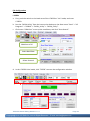
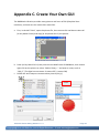
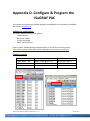
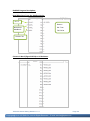
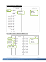
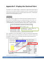
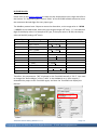
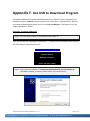
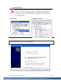


![[:SOURce]:BB:GSM[:FRAMe]](http://vs1.manualzilla.com/store/data/005841236_1-e838b09572e81e9a2469fdab27d799a4-150x150.png)