1
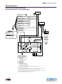
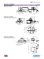
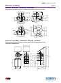
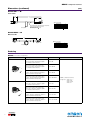
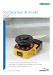
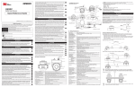
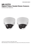
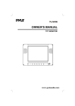
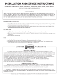
Safety Laser Scanners
OS32C
S224
Compact Safety Laser Scanner
Industry First!
EtherNet/IP Capable for Status and Measurement
Data Reporting
• 4 m safety range models
• Pollution tolerance modes provide improved performance in dusty
environments
• Compact size (104.5 mm height), power efficient (5 W) and
light weight (1.3 kg) for longer AGV battery life
• 70 sets of safety zone and warning zone combinations, for
complex changes in zone guarding parameters
• Configuration memory and I/O block, no need to reprogram
after sensor replacement, minimal down time
• Configurable minimum object resolution of 30, 40, 50 or 70 mm,
for hand and arm detection applications
• 8 Individual Sector Indicators and LED indicators, determine
scanner status at a glance
• Easy-to-use Software Tool simplifies creation of complex zone
combinations
TUV
Rheinland
4 m Safety Range Models
4 m Safety Zone
15 m Warning Zone
Safety Zone
4 m Max.
Detection Angle
270° Max.
Warning Zones 1 & 2
15 m Max.
EtherNet/IP for Status and Measurement Data
The OS32C with EtherNet/IP can
be monitored by ODVA EtherNet/IP
compliant products such as PLCs
and HMIs. System status, zone
status, and measurement data can
all be monitored over EtherNet/IP.
EtherNet/IP
Scanner Safety Outputs
1
OS32C
Safety Laser Scanners
Specifications
Sensor Type
Type 3 Safety Laser Scanner
Safety Category
Category 3, Performance Level d (ISO13849-1: 2008)
Detection Capability
Configurable; Non-transparent with a diameter of 30, 40, 50 or 70 mm (1.8% reflectivity or greater)
Monitoring Zone
Monitoring Zone Set Count: (Safety Zone + 2 Warning Zones) x 70 sets
Operating
Range
OS32C-XX
Safety zone: 1.75 m (min. object resolution of 30 mm), 2.5 m (min. object resolution of 40 mm), 3.0 m (min. object
resolution of 50 mm or 70 mm); Warning Zone: 10 m
OS32C-XX-4M
Safety zone: 1.75 m (min. object resolution of 30 mm), 3.0 m (min. object resolution of 50 mm or 70 mm), 4.0 m (min.
object resolution 70 mm); Warning Zone: 15 m
Maximum Measurement Error
100 mm (at less than 3 m distance); 110 mm (at greater than 3 m distance) *1
Detection Angle
270°
Angular Resolution
0.4°
Laser Beam Diameter
6 mm at optics cover, 14 mm at 3 m.
Laser Scan Plane Height
67 mm from the bottom of the scanner (see dimensional drawings for more detail)
Response Time
Response time from ON to OFF: From 80 ms (2 scans) to 680 ms (up to 17 scans) *8
Response time from OFF to ON: Response time from ON to OFF + 100 ms to 60 s (configurable)
Zone Switching Time
20 to 320 ms
Line Voltage
24 VDC +25%/-30% (ripple p-p 2.5 V max.) *2
Power Consumption
Normal operation: 5 W max., 4 W typical (without output load) *3
Standby mode: 3.75 W (without output load)
Emission Source (Wavelength)
Infrared Laser Diode (905 nm)
Laser Protection Class
Class 1: IEC/EN60825-1 (2007); Class 1: JIS6802 (2005); Class I: CFR21 1040.10, 1040.11
Safety Output (OSSD)
PNP transistor x 2, load current of 250 mA max., residual voltage of 2 V max.,
load capacity of 2.2 µf max., leak current of 1 mA max. *3, *4, *5
Auxiliary Output (Non-Safety)
NPN/PNP transistor x 1, load current of 100 mA max., residual voltage of 2 V max., leak current of 1 mA max. *4, *5, *7
Warning Output (Non-Safety)
NPN/PNP transistor x 1, load current of 100 mA max., residual voltage of 2 V max., leak current of 1 mA max. *4, *5, *7
Output Operation Mode
Auto Start, Start Interlock, Start/Restart Interlock
Input
External Device
Monitoring (EDM)
ON: 0 V short (input current of 50 mA), OFF: Open
Start
ON: 0 V short (input current of 20 mA), OFF: Open
Zone Select
ON: 24 V short (input current of 5 mA), OFF: Open
Stand-by
ON: 24 V short (input current of 5 mA), OFF: Open
Connection Type
Power Cable: 18-pin mini-connector (pigtail); Communication Cable: M12, 4-pin connector
Connection with PC *6
Communication: Ethernet
OS Supported: Windows 2000, Windows XP, Windows Vista, or Windows 7
Indicators
RUN indicator: Green, STOP indicator: Red, Interlock Indicator: Yellow, Warning Output Indicator: Orange,
Status/Diagnostic Display: 2 x 7-segment LEDs, Intrusion Indicators: Red LED x 8
Protective Circuit
Protection against output load short and reverse power connection
Ambient Temperature
Operation: -10 to 50°C, Storage: -25 to 70°C
Ambient Humidity
Operation & Storage: 95% RH max., non-condensing
Ambient Operation Illumination
Incandescent lamp: Illumination on receiving surface 1500 lx max. (an angle of laser scanning plane and disturbance
light must be ±5 degrees or more)
Enclosure Rating
IP65 (IEC60529)
Enclosure
Sensor head: Die-cast aluminum, optical cover: Polycarbonate, I/O block: Die-cast aluminum
Dimensions (W x H x D)
133.0 x 104.5 x 142.7 mm (except cable)
Dielectric Withstand Voltage
350 VAC, 50/60 Hz, 1 minute
Insulation Resistance
20 mega-ohm or higher (500 VDC)
Impact Resistance
98 m/s2 1,000 times for each of X, Y, and Z directions (IEC 60068-2-29)
Vibration
10 to 55 Hz double-amplitude of 0.7 mm, 20 sweepings for X, Y, and Z directions (IEC60068-2-6)
Weight (Main Unit only)
1.3 kg
Power Cable
Up to 30 m
Communication Cable
Up to 100 m for 100 BASE-T Cat 5 cable
Accessories
CD-ROM (User’s Manual and Configuration Tool)
Approvals
EN61496-1 (Type 3 ESPE), EN61496-3 (Type 3 AOPDDR), EN61508 (SIL2),
IEC61496-1 (Type 3 ESPE), IEC61496-3 (Type 3 AOPDDR), IEC61508 (SIL2),
UL508, UL1998, CAN/CSA-C22.2 No. 14, -CAN/CSA-C22.2 No. 0.8
*1. An additional measurement error may need to be added due to
reflective backgrounds.
*2. For power source specification, contact OMRON Automation and Safety.
*3. Rated current of OS32C is 1.025 A max. (OS32C 210 mA + OSSD A load
+ OSSD B load + Auxiliary output load + Warning output load + Functional
Inputs). Where functional inputs are: EDM input – 50 mA, Start input– 20 mA,
Standby input –5 mA, Zone X input – 5 mA x 8 (8 zone set select inputs)
2
*4. Output voltage is Input voltage - 2.0 VDC.
*5. Total consumption current of 2 OSSDs, auxiliary output, and warning
output must not exceed 700 mA.
*6. An Ethernet cable with an M12, 4-pin connector is required.
*7. Output polarity (NPN/PNP) is configurable via the configuration tool.
*8. Pollution tolerance model will add 6 m/sec. to each scan time.
OS32C
Safety Laser Scanners
System Components and Functions
(9)
(10)
(11)
(8)
(7)
(6)
(12)
(13)
(5)
(1)
(2)
Number
(1)
(3)
(4)
Component
Function
RUN indicator (green)
Will turn ON when safety zone is clear and OSSDs are ON.
(2)
Interlock Indicator (yellow)
Will turn ON when in interlock state, blink under lockout, and blink in case of a failure.
(3)
Status/Diagnostic Display
The scanner status, configuration/operation, or failure is displayed.
Will turn ON when the warning output is ON.
(4)
Warning Output Indicator (orange)
(5)
STOP indicator (red)
Will turn ON when safety zone is blocked, OSSDs are OFF or under interlock state.
(6)
Dust Ring
Dust detection cover with reflective surface, for dust accumulation detection
(7)
Individual Sector Indicators
Will turn ON when an intrusion is detected in the safety zone, 8 sectors total. Each sector = 33.75°.
(8)
Scan window
The window where the laser light is emitted and received.
(9)
Ethernet Cable
Used for Ethernet cable connection. *
(10)
Power Connector
18-pin connector (pigtail). *
(11)
I/O Block
Connector module
(12)
Center of rotation
Indicates the location of the axis around which the laser emits.
(13)
Sensor block
Sensor head; field replaceable.
*For OS32C-SP1, each connector is located on the left as viewed from the back of the I/O block.
3
OS32C
Safety Laser Scanners
Wiring
Basic Connection with Single OS32C Unit
Category 3, Performance Level d (ISO13849-1)
PE
0V
Functional Earth (Green)
E1
+24V
24VDC (White)
0VDC (Brown)
S3
Standby input (Violet)
Zone Select 1 (Orange/White)
*4
S2
Zone Select 2 (Orange/Black)
*4
S2
Zone Select 3 (Gray)
*4
Zone Select 4 (Pink)
S2
*4
Zone Select 5 (White/Black)
S2
*4
S2
Zone Select 6 (Tan)
*4
S2
Zone Select 7 (Orange)
*4
Zone Select 8 (Blue/White)
*4
S2
Start (Black)
*3
S1
Auxiliary output (Blue)
Warning output (Red/Black)
S1 : Start Input
S2 : Zone Select Switch
S3 : Standby Switch
ED1, ED2: Forced guided relay
M1 : 3-Phase Motor
E1 : 24 VDC Power
S2
*2 ED1 ED2
EDM (Brown/White)
ED1
Safety output B (Yellow)
Safety output A (Red)
*1
*1
ED1
ED2
ED2
M1
*1. External devices (ED1, ED2) are forced guide relays. (G7Z, G7SA, G7S, etc)
*2. If the External Device Monitoring is not used, connect brown/white wires to 0 V, and
then turn OFF the External Device Monitoring with the configuration software.
*3. Use NC-contact for a start input.
*4. For zone select switch setting, refer to OS32C Series User’s Manual. When using
only one zone, no connection is needed for the zone select inputs.
Note: This wiring example is for category 3.
OS32C Configuration
- External Device Monitoring Enabled
- Start/Restart Interlock
Connection to AGV Controls
Category 3, Performance Level d (ISO13849-1)
AGV Controls
Functional Earth (Green)
Power (24VDC)
24VDC (White)
0VDC (Brown)
Standby input (Violet)
Zone Control
Zone Select 1 (Orange/White)
Zone Select 2 (Orange/Black)
+24VDC
Zone Select 3 (Gray)
Zone Select 4 (Pink)
Zone Select 5 (White/Black)
Zone Select 6 (Tan)
Zone Select 7 (Orange)
Zone Select 8 (Blue/White)
Start (Black)
Auxiliary output(Blue)
Auxiliary Control
0VDC
Warning output (Red/Black)
EDM (Brown/White)
Safety output B (Yellow)
Stop/Brake Control
Safety output A (Red)
Note: This wiring example is for category 3.
OS32C Configuration
- External Device Monitoring Disabled
- Automatic Start
4
OS32C
Safety Laser Scanners
Wiring (continued)
Connecting to the Controller G9SA-301
Category 3, Performance Level d (ISO13849-1)
E1
PE
0V
+24V
Functional Earth (Green)
24VDC (White)
0VDC (Brown)
S4
Standby input (Violet)
*4
S2
Zone Select 2 (Orange/Balck)
*4
Zone Select 3 (Gray)
S2
*4
Zone Select 4 (Pink)
S2
*4
Zone Select 5 (White/Black)
*4
S2
Zone Select 6 (Tan)
*4
Zone Select 1 (Orange/White)
Zone Select 7 (Orange)
*4
Zone Select 8 (Blue/White)
*4
S2
PLC
S2
S2
IN1
S2
Start (Black)
S1
Auxiliary output (Blue)
IN2
OUT
*2
Warning output (Red/Black)
EDM (Brown/White) *3
Safety output B (Yellow)
Safety output A (Red)
ED3
*1
ED1
ED1
S3
A1 A2 T11
T12
*1
ED2
ED2
T31 T32
13
23
33
41
3
4
a
K2
K1
K1
b
K2
M
K1
1
K2
a
b
Control
Circuit
2
5
JP
1
2
3
4
5
6
6
PE T21
T23 T22
A
14
B
*1
ED1
24
34
42
ED2 *1
ED1, ED2: Forced guided relay
ED3 : Solid state contactor (G3J)
M : 3-Phase Motor
S1 : Start Input
(use for releasing lockout)
S2 : Zone Select Switch
S4 : Standby Switch
S3 : Reset Switch
E1 : 24 VDC Power
PLC : Programmable Controller
(This is for monitoring only and
unrelated to a safety system)
*1. External devices (ED1, ED2) are forced guide relays. (G7Z, G7SA, G7S, etc)
*2. Use NC-contact for a start input.
*3. If the External Device Monitoring is not used, connect brown/white wires to 0V, and then
turn OFF the External Device Monitoring with the configuration software.
*4. For zone select switch setting, refer to OS32C Series User’s Manual. When using only one
zone, no connection is needed for the zone select inputs.
Note: This wiring example is for category 3.
5
OS32C
Safety Laser Scanners
Dimensions
mm (in.)
OS32C-BP
OS32C with Back Location Cable Entry
Ethernet cable not shown
Ethernet connector
with M12 cap plug
I/O cable
90.4 [3.56]
Window
158.3 [6.24]
Dust
detection
I/O block
Sensor head
104.3 [4.11]
140.4 [5.53]
Top View
100.0 [3.94]
133.0 [5.24]
32.8 [1.29]
M5×0.8 (x4)
41.4 [1.63]
MTG holes
57.0 [2.25]
27.7 [1.09]
50.0 [1.97]
104.5 [4.12]
67.0 [2.64]
Scan plane
Front View
6.0 [0.24]
121.0 [4.77]
MTG holes
Side View
Back View
102.9 [4.05]
142.7
[5.62]
I/O cable assy
88.1
[3.47] 71.5
[2.82]
71.3[2.81]
(min)
Ethernet
cable
2.0, 3.0, 10.0, 20.0, or 30.0 Meters
ø30.0 [1.18] OD
I/O cable
Bottom View
OS32C-SP1
50.9 [2.01]
270 [10.63]
OS32C with Side Location Cable Entry
I/O block
Ethernet
cable
90.4 [3.56]
Ethernet cable
Window
Dust
detection
I/O cable
Sensor head
104.3 [4.11]
Top View
133.0 [5.24]
140.4 [5.53]
M5×0.8(×4)
67.0 [2.64]
Scan plane
Back View
Front View
6.0 [0.24]
57.0 [2.25]
Side View
50.4 [1.99]
I/O cable
142.7
[5.62]
88.2
[3.47]
270 [10.63]
102.9 [4.05]
71.5
[2.82]
Bottom View
6
32.8 [1.29]
104.5 [4.12]
41.4 [1.63]
MTG holes
121.0 [4.77]
MTG holes
100.0 [3.94]
70.8
[2.79]
I/O cable assy
2.0, 3.0, 10.0, 20.0, or 30.0 Meters
ø30.0 [1.18] OD
OS32C
Safety Laser Scanners
Dimensions (continued)
mm (in.)
OS32C-BP + OS32C-BKT4
150.4 [5.93]
ø107.5 [4.24]
OS32C with Top Guard Kit
93.4 [3.68]
112.4 [4.43]
67.0 [2.64]
Scan Plane
41.4 [1.63] 63.0 [2.48]
27.7 [1.09]
6.0 [0.24]
50.0 [1.97]
145.7 [5.74]
121.0 [4.77]
Side View
Back View
OS32C-BP + OS32C-BKT1
103.7 [4.08]
97.7 [3.85]
OS32C with Bottom/Side Mounting Brackets
69.2
[2.73]
39.9 [1.57]
116.7
[4.60]
12.2 [0.48]
50.0 [1.97]
4.9 [0.19]
79.2 [3.12]
Scan plane
24.5 [0.97]
23.3 [0.92]
41.0 [1.62]
Back View
37. 9 [1.49]
93.7 [3.69]
Side View
155.9 [6.14]
106.0 [4.17]
102.4 [4.03]
66.4
[2.62]
144.4 [5.69]
54.5 [2.15]
Bottom View
OS32C-BP + OS32C-BKT3
23.3 [0.92]
103.4 [4.08]
OS32C with Simple Mounting Brackets
104.5
[4.12]
67.0 [2.64]
Scan plane
52.8
[2.08]
26.8 [1.05]
(×4) 12.0 [0.47]
SYM
13.3 [0.52]
50.0
[1.97]
169.0 [6.66]
155.7 [6.13]
Back View
Side View
(×4) Slots for M5 mounting screws
“hardware user supplied”
185.0 [7.29]
Bottom View
7
OS32C
Safety Laser Scanners
Dimensions (continued)
mm (in.)
OS32C-BP + OS32C-BKT1 + OS32C-BKT4
OS32C with Bottom/Side Mounting Brackets and Top Guard Kit
154.7 [6.09]
103.7 [4.08]
φ107.5 [4.24]
97.7 [3.85]
75.2
[2.96]
39.9 [1.57]
124.9
[4.92]
12.2 [0.48]
50.0 [1.97]
4.9 [0.19]
79.2 [3.12]
Scan plane
4.8 [0.19]
Back View
24.5 [0.97]
23.3 [0.92]
41.0 [1.62]
37.9 [1.49]
93.7 [3.69]
Side View
155.9 [6.14]
106.0 [4.17]
66.4
[2.62]
144.4 102.4
[5.69] [4.03]
54.5 [2.15]
23.3 [0.92]
Bottom View
OS32C-BP + OS32C-BKT1 + OS32C-BKT2
OS32C with XY Axis Rotation Mounting Kit
111. 4 [4.39]
132.7 [5.23]
95.2 [3.75]
Scan plane
48.0 [1.89]
55.9 [2.20]
50.0 [1.97]
15.0
7.5
28.2 [1.11]
17.0
[0.67]
93.5 [3.68]
150.5 [5.93]
46.0 [1.81]
Back View
(For back mounting)
15.0
47.5 [1.87] 166.3
[6.55]
Side View
151.1
[5.95]
102.4
[4.03]
42.2 [1.66]
139.7 [5.50]
Back View
(For Y-anglular adjustment)
8
99.2
[3.91]
163.7 [6.45]
119.7 [4.72]
7.5
Hardware for
Y-adjustment
43.0
[1.69]
17.4
[0.69]
54.5 [2.15]
Bottom View
37.0 [1.46]
163.0
[6.42]
OS32C
Safety Laser Scanners
Dimensions (continued)
mm (in.)
OS32C-BP + OS32C-BKT1 + OS32C-BKT2 + OS32C-BKT4
OS32C with Bottom/Side Mounting Brackets and XY Axis Rotation Mounting Kit and Top Guard Kit
168.4 [6.63]
111.4 [4.39]
φ107.5 [4.24]
141.0 [5.55]
48.0 [1.89]
55.9 [2.20]
95.2 [3.75]
Scan plane
99.2 [3.91]
28.2 [1.11]
50.0 [1.97]
93.5 [3.68]
150.5 [5.93]
17.0 [0.67]
4.8 [0.19]
46.0 [1.81]
Side View
Back View
(For back mounting)
15.0
163.7 [6.45]
119.7 [4.72]
7.5
Hardware for
Y-adjustment
7.5
15.0 43.0 [1.69]
47.5 [1.87] 166.3 151.1
[6.55] [5.95]
42.2 [1.66]
102.4 163.0
[4.03] [6.42]
17.4 [0.69]
139.7 [5.50]
Back View
(For Y-angular adjustment)
54.5 [2.15]
37.0 [1.46]
Bottom side
OS32C-SP1 + OS32C-BKT1 + OS32C-BKT2 + OS32C-MT + OS32C-HDT
OS32C with Bottom/Side Mounting Brackets and XY Axis Rotation Mounting Kit and Mounting Stand
and Mounting Stand Hardware Kit
203.2 [8.00]
609.6 [24.00]
637.2 [25.09]
137.2 [5.40]
424.0 [16.69]
355.1 [13.98]
286. 2 [11.27]
209.6 [8.25]
217.3 [8.56]
165.1 [6.50]
190.5 [7.50]
View A
A
111.7
[4.40]
235.0 [9.25]
250.8 [9.87]
9
OS32C
Safety Laser Scanners
Dimensions (continued)
(mm)
OS32C-CBL-□□M
Power Cable
L
(56)
(90)
(30)
Sizes are as below
Model Number
OS32C-CBL-03M
OS32C-CBL-10M
OS32C-CBL-20M
Vinyl insulated round cable (diameter max. 10mm) Black
18-core (conductor section area 0.3 mm2,
insulator diameter max. 1.5 mm)
Standard length L (See )
Name plate
OS32C-CBL-30M
L
3m
10m
20m
30m
OS32C-ECBL-□□M
Ethernet Cable
D-coding
3
4
44.7
L
6.5 dia.
54.7
1
2
Sizes are as below
M12
Model Number
OS32C-ECBL-02M
RJ45 TYPE
Twist tie
OS32C-ECBL-05M
OS32C-ECBL-15M
L
2m
5m
15m
Ordering
OS32C (Power cable is sold separately)
Appearance
Description
Model
OS32C laser scanner with 3 m range and
back location cable entry EtherNet capable
for configuration and monitoring
OS32C-BP
OS32C laser scanner with 4 m range and
back location cable entry EtherNet capable
for configuration and monitoring
OS32C-BP-4M
OS32C laser scanner with 3 m range, back
location cable entry EtherNet/IP capable for
status measurement data reporting
OS32C-BP-DM
OS32C laser scanner with 4 m range, back
location cable entry EtherNet/IP capable for
status measurement data reporting
OS32C-BP-DM-4M
OS32C laser scanner with 3 m range and
side location cable entry*, EtherNet capable
for configuration and monitoring
OS32C-SP1
OS32C laser scanner with 4 m range and
side location cable entry*, EtherNet capable
for configuration and monitoring
OS32C-SP1-4M
OS32C laser scanner with 3 m range, side
location cable entry*, EtherNet/IP capable for
status measurement data reporting
OS32C-SP1-DM
OS32C laser scanner with 4 m range, side
location cable entry*, EtherNet/IP capable for
status measurement data reporting
OS32C-SP1-DM-4M
*For OS32C-SP1, each connector is located on the left as viewed from the back of the I/O block.
10
Remarks
CD-ROM (Configuration software)
OS supported: Windows 2000, Windows XP, Windows Vista
Windows 7
OS32C
Safety Laser Scanners
Ordering (continued)
Power Cable
Appearance
Ethernet Cable
Appearance
Description
Model
Cable length: 3 m
OS32C-CBL-03M
Cable length: 10 m
OS32C-CBL-10M
Cable length: 20 m
OS32C-CBL-20M
Cable length: 30 m
OS32C-CBL-30M
Description
Model
Cable length: 2 m
OS32C-ECBL-02M
Cable length: 5 m
OS32C-ECBL-05M
Cable length: 15 m
OS32C-ECBL-15M
Remarks
One cable is required per sensor.
Remarks
Required for configuration and monitoring.
Note: An EtherNet cable with an M12, 4-pin connector is required.
Mounting Brackets
Appearance
Description
Model
Remarks
Bottom/side mounting bracket
OS32C-BKT1
Bottom/side mounting bracket x 1,
unit mounting screws x 4 sets
XY axis rotation mounting bracket
OS32C-BKT2
XY axis rotation mounting bracket x 1,
unit mounting screws x 6 sets,
bracket mounting screws x 1 set
(must be used with OS32C-BKT1)
Simple mounting bracket
OS32C-BKT3
Simple mounting brackets x 2,
unit mounting screws x 4 sets *
Protective cover for window
OS32C-BKT4
Mounting stand
OS32C-MT
When using a mounting stand, use an OS32C
with side location cable entry (OS32C-SP1).
The OS32C with back location cable entry
(OS32C-BP) cannot be mounted.
Use with mounting brackets (OS32C-BKT1
and OS32C-BKT2).
Hardware kit for mounting stand
OS32C-HDT
Mounting screws x 3 sets
Use this when mounting a bracket to the
mounting stand.
*There are eight OS32C mounting screws for singular use, and four screws for protective cover for window.
11
OS32C
Safety Laser Scanners
Ordering (continued)
Accessories
Appearance
Description
Model
Remarks
Scan window
OS32C-WIN-KT
Spare for replacement
Spare sensor with 3 m range, without I/O
block, EtherNet capable for configuration
and monitoring
OS32C-SN
Spare for replacement
Spare sensor with 4 m range, without I/O
block, EtherNet capable for configuration
and monitoring
OS32C-SN-4M
Spare for replacement
Spare sensor with 3 m range, EtherNet/IP,
without I/O block, EtherNet/IP capable for
status and measurement data reporting
OS32C-SN-DM
Spare replacement for EtherNet/IP
Spare sensor with 4 m range, EtherNet/IP,
without I/O block, EtherNet/IP capable for
status and measurement data reporting
OS32C-SN-DM-4M
Spare replacement for EtherNet/IP
I/O block with cable access from the back
OS32C-CBBP
Spare for replacement
I/O block with cable access from the left side
OS32C-CBSP1
Spare for replacement
Window cleaning kit, anti-static cleaner
WIN-CLN-KT
Accessory
OMRON AUTOMATION AND SAFETY • THE AMERICAS HEADQUARTERS • Chicago, IL USA • 847.843.7900 • 800.556.6766 • www.omron247.com
OMRON CANADA, INC. • HEAD OFFICE
Toronto, ON, Canada • 416.286.6465 • 866.986.6766 • www.omron247.com
OMRON ARGENTINA • SALES OFFICE
Cono Sur • 54.11.4783.5300
OMRON ELECTRONICS DE MEXICO • HEAD OFFICE
México DF • 52.55.59.01.43.00 • 01-800-226-6766 • [email protected]
OMRON CHILE • SALES OFFICE
Santiago • 56.9.9917.3920
OMRON ELECTRONICS DE MEXICO • SALES OFFICE
Apodaca, N.L. • 52.81.11.56.99.20 • 01-800-226-6766 • [email protected]
OTHER OMRON LATIN AMERICA SALES
54.11.4783.5300
OMRON ELETRÔNICA DO BRASIL LTDA • HEAD OFFICE
São Paulo, SP, Brasil • 55.11.2101.6300 • www.omron.com.br
OMRON EUROPE B.V. • Wegalaan 67-69, NL-2132 JD, Hoofddorp, The Netherlands. • +31 (0) 23 568 13 00 • www.industrial.omron.eu
F38I-E-02
Note: Specifications are subject to change.
© 2015 Omron Electronics LLC
Printed in U.S.A.