1
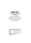
www.stockflightsystems.com
PMC825 User’s Manual
Date:
14.6.2010
Version:
1.2
Author:
Michael Stock
Innovative Control Systems, Inc.
10801 N 24th Ave. Suite 103
Phoenix, AZ 85029
USA
phone: +1-602-564-0851
fax: +1-602-588-9440
e-mail: [email protected]
website: www.icsaero.com
Products covered:
Innovative Control
Systems, Inc.
Stock Flight Systems
Wetzel Technology GmbH
PMC825
PowerNECS
Wetzel Technology GmbH
Hermann-Oberth-Straße 11
85640 Putzbrunn
Germany
phone: +49-89-46089262
fax: +49-89-46089263
e-mail: [email protected]
website: www.wetzel-technology.com
Stock Flight Systems
Schützenweg 8a
82335 Berg/Farchach
Germany
phone: +49-8151-9607-0
fax: +49-8151-9607-30
e-mail: [email protected]
website: www.stockflightsystems.com
PMC825_Users_Manual_V1.2.pdf
page: 1 of 26
www.stockflightsystems.com
PMC825 User’s Manual
Innovative Control
Systems, Inc.
Stock Flight Systems
Wetzel Technology GmbH
Table of Contents
Section
Title
Page
1
2
3
4
5
6
7
8
9
10
11
12
13
14
15
Overview
PMC825 Front Panel Connectors
PowerNECS Front Panel Connectors
CAN Activity LEDs
PMC Connectors
Firmware Status LEDs
MicroSD Card Slot
Ethernet Interface
PMC825 Configuration File
PMC825 Firmware Upgrades
PMC825 Socket Interface Library
XCT Toolbox Overview
PCI Interface Driver (Linux)
PCI Interface Driver (Windows)
PCI Interface Driver (VxWorks)
3
6
7
8
8
9
10
11
12
16
17
22
x
x
x
PMC825_Users_Manual_V1.2.pdf
page: 2 of 26
www.stockflightsystems.com
PMC825 User’s Manual
Innovative Control
Systems, Inc.
Stock Flight Systems
Wetzel Technology GmbH
1. Overview
The PMC825 PCI Mezzanine Card (PMC) plug-in board offers 4 or 8 optically isolated CAN 2.0B interfaces according to ISO 11898 and a 10/100/1000 BaseT Ethernet interface. To minimize CPU
load on host computers, the PMC825 uses an onboard Xilinx Virtex-4 FPGA with dual PowerPC 405
processors and 8 MByte DRAM to process and store CAN messages. The PCI bus interface is realized using a PLX PCI9656 bridge chip. The CAN bus interfaces are accessible via a 26-pin micro
D-Sub connector. Figure 1 shows the PMC-825 board.
Figure 1: PMC825 Board
The PMC825 features are:
• PMC form factor
• 64-bit, 66 MHz PCI interface
• 4/8 optically isolated ARINC 825 interfaces per module
• Licensed Bosch CAN controller IP cores implemented in Xilinx Virtex-4 FX60 FPGA
• Dual on-chip 192 MHz PowerPC 405 processors
• Shared RAM interface between PCI host and PMC825
• PMC carriers for platform diversity (PCI, cPCI, PCI-X, PCI Express, VME)
• Module firmware supports record/playback functions and high resolution timestamping
• PCI host drivers for Linux/X86, Solaris/SPARC, VxWorks and Windows XP/7
• XCT window-oriented toolbox for Linux and Windows XP/7 with PMC825 Ethernet/UDP/IP
interface
• Human-readable module configuration file for CAN/Ethernet interfaces on MicroSDHC card
• MicroSD card based firmware upgrade mechanism
• Standalone version with integrated power supply (product name: PowerNECS) available
PMC825_Users_Manual_V1.2.pdf
page: 3 of 26
www.stockflightsystems.com
PMC825 User’s Manual
Innovative Control
Systems, Inc.
Stock Flight Systems
Wetzel Technology GmbH
The PMC825 is a standalone computer system and an intelligent PCI slave device that utilizes its
processing power to relief external computer systems from the tasks of transmitting, receiving, buffering and pre/postprocessing low, medium or high-speed CAN, CANaerospace and ARINC 825
messages. It can handle up to 100% bus load at the maximum CAN data rate of 1MBit/s on all
channels without data loss. The driver software provides an easy-to-handle function call interface
for CAN bus message transmission and reception including support for the CANaerospace and
ARINC 825 higher layer protocols. The PMC-825 software consists of PCI host drivers for various
operating systems and platforms, sample “C” source code and the Qt-based XCT toolbox connected to the PMC825 via Ethernet/UDP/IP. Figure 2 shows a simplified block diagram of the PMC825
board.
PMC (PCI) Connectors
Shared
DDRAM
(8 MB)
PCI
Bridge Chip
(PLX 9656)
microSD
Card
Slot
Program
FLASH
(128 MB)
CPU 1
PPC 405
(192 MHz)
CPU 2
PPC 405
(192 MHz)
RS-232/
RS-422
Controller
8 Bosch
C_CAN
Controllers
TEMAC
Ethernet
Controller
MagJack
Ethernet
PHY
Figure 2: Simplified PMC825 Block Diagram
The standalone version of the PMC825 is packaged in an aluminum housing as shown in figure 3.
and contains an internal power supply unit. This unit is a member of the Network Extended Control
PMC825_Users_Manual_V1.2.pdf
page: 4 of 26
www.stockflightsystems.com
PMC825 User’s Manual
Innovative Control
Systems, Inc.
Stock Flight Systems
Wetzel Technology GmbH
System (NECS) family of embedded computer systems and is referred to as PowerNECS. PowerNECS is sealed against electromagnetic interference and operates from a 9-36 VDC power supply according to the EN 2282:1992 characteristics of aircraft electrical supplies. The power
consumption is < 15 W, the box dimensions are 172 x 92 x 70.6 mm, the weight is 0.5 kg. Figure 4
shows the mechanical dimensions of the PowerNECS enclosure.
Figure 3: PowerNECS based on PMC825
All dimensions in mm
Figure 4: PowerNECS Mechanical Dimensions
PMC825_Users_Manual_V1.2.pdf
page: 5 of 26
www.stockflightsystems.com
PMC825 User’s Manual
Innovative Control
Systems, Inc.
Stock Flight Systems
Wetzel Technology GmbH
2. PMC825 Front Panel Connectors
The PMC825 module has two front panel connectors. The connector to the right is dedicated to the
Ethernet interface and uses a MagJack L829-1J1T-43 Integrated Connector Module. The pinout of
this connector is according to the established RJ-45 standard and shown in figure 5.
The Micro Sub-D front panel connector combines the CAN interfaces and additional RS-232, RS422 and signals for future use as shown in figure 6. Pins 10-13 and 23-25 of this connector should
not be connected and left open unless supported by a customized firmware available on request.
The CAN Ground signals can be used to connect systems with non-isolated CAN transceivers to
the PMC825. For isolated networks using CAN Low and CAN High only, the CAN Ground pins may
be left unconnected.
LED 2 (green: 100Mbit/s, amber: 1000Mbit/s)
LED 1 (TX)
Pin
Name
Description
1
TX+
Transmit Data +
2
TX-
Transmit Data -
3
RX+
Receive Data +
4-5
nc
Not Connected
6
RX-
Receive Data -
7-8
n
Not Connected
1 2 3 4 5 6 7 8
Figure 5: RJ45 Ethernet Connector Pinout
RS-232 Ground
RS-232 Tx
RS-485 Inverting
Line In L
CAN Ground
CAN High Channel 7
CAN High Channel 3
CAN High Channel 6
CAN High Channel 2
CAN High Channel 5
CAN High Channel 1
CAN High Channel 4
CAN High Channel 0
13
12
11
10
9
8
7
6
5
4
3
2
1
25
24
23
22
21
20
19
18
17
16
15
14
RS-232 Rx
RS-485 Non-Inverting
Line In R
CAN Ground
CAN Low Channel 7
CAN Low Channel 3
CAN Low Channel 6
CAN Low Channel 2
CAN Low Channel 5
CAN Low Channel 1
CAN Low Channel 4
CAN Low Channel 0
Figure 6: 25-Pin Micro Sub-D Connector Pinout
PMC825_Users_Manual_V1.2.pdf
page: 6 of 26
www.stockflightsystems.com
PMC825 User’s Manual
Innovative Control
Systems, Inc.
Stock Flight Systems
Wetzel Technology GmbH
3. PowerNECS Front Panel Connectors
Aside from the PMC825 front panel connectors, the PowerNECS offers two additional 9-pin D-Sub
connectors located above the PMC825 bezel. These connectors are used to supply PowerNECS
with 9-36VDC input power and also provide access to CAN channel 0 of the PMC825. The corresponding pinout is compatible with the CANaerospace and ARINC 825 specifications and shown in
figure 7. The pins 1, 2, 5 and 7 of both connectors are internally connected so that both connectors
are functionally identical. Figure 8 shows the internal routing of the CAN interface #0 lines.
Power Ground
Not connected, reserved for future use
Not connected, reserved for future use
CAN Low Channel 0
Power +9-36VDC
5
4
3
2
1
9
8
7
6
Not connected, reserved for future use
Not connected, reserved for future use
CAN High Channel 0
Not connected, reserved for future use
Power +9-36VDC
CAN Low Channel 0
Not connected, reserved for future use
Not connected, reserved for future use
Power Ground
1
2
3
4
5
6
7
8
9
Not connected, reserved for future use
CAN High Channel 0
Not connected, reserved for future use
Not connected, reserved for future use
Figure 7: PowerNECS Front Panel Connector Pinout
10
5
CAN-H Channel 0
6
1
1
6
5
10
(25-Pin D-Sub Connector Front View)
CAN-L Channel 0
Figure 8: Internal routing of CAN Interface #0 lines to PowerNECS Front Panel Connector
PMC825_Users_Manual_V1.2.pdf
page: 7 of 26
www.stockflightsystems.com
PMC825 User’s Manual
Innovative Control
Systems, Inc.
Stock Flight Systems
Wetzel Technology GmbH
4. CAN Activity LEDs
The CAN activity LEDs located on the front panel (see figure 9) indicate if a CAN channel transmits
and/or receives CAN messages. Every CAN channels has a dedicated activity LED which flashes
once for every transmitted/received message or continuously at a rate of 2Hz in case of a steady
message flow. If the activity LED of a particular CAN channel stays dark in an active network, the
physical interface correctness of all network nodes including the used baud rates, sample points
and termination resistors should be verified.
Figure 9: CAN Activity LEDs (4 Channel PMC825)
5. PMC Connectors
The PMC825 is fully compatible to the IEEE P1386.1 standard. The PMC connector pinout is shown
in figures 10 and 11.
Figure 10: PMC825 Pn1/Pn2 Connector Pinout
PMC825_Users_Manual_V1.2.pdf
page: 8 of 26
www.stockflightsystems.com
PMC825 User’s Manual
Innovative Control
Systems, Inc.
Stock Flight Systems
Wetzel Technology GmbH
Figure 11: PMC825 Pn3/Pn4 Connector Pinout
6. Firmware Status LEDs
Seven status LEDs are located on the card edge of the PMC825 is shown in figure 12. The firmware
run LEDs flash alternating between DS6/4 and DS5/3 during normal operation.
PMC-825 Board
1 2 3 4 5 6 7
LED
Name
Description
1
DONE
FPGA Config Finished
2
INIT
FPGA Config Started
3
PV
Power Valid
4-7
DS6 - DS3
Firmware Run LEDs
Figure 12: PMC825 Status LED Assignment
PMC825_Users_Manual_V1.2.pdf
page: 9 of 26
www.stockflightsystems.com
PMC825 User’s Manual
Innovative Control
Systems, Inc.
Stock Flight Systems
Wetzel Technology GmbH
7. MicroSD Card Slot
The PMC825 offers a MicroSD card slot that supports FAT16 or FAT32 formatted MicroSD and
MicroSDHC cards. MicroSD cards used with the PMC825 have to support the Serial Peripheral Interface (SPI) mode and be capable of operating under a sustained SPI data rate of 25 MHz. The
card slot pinout of the PMC825 is shown in figure 13 and is fully compatible with the MicroSD specification of the SD Card Organization (www.sdcard.org).
The MicroSD card interface is used to configure the PMC825 during startup using a dedicated configuration file (see section 9) and to perform firmware upgrades (see section 10). Options for CAN
data recording on MicroSDHC card are available on request.
Pin
Name
Description
1
RSD
Reserved
2
CS
Chip Select (low active)
3
DI
Data In
4
VDD
Supply Voltage
5
SCK
System Clock
6
VSS
Supply Voltage Ground
7
DO
Data Out
8
RSD
Reserved
Figure 13: MicroSD/MicroSDHC Card Pinout
PMC825_Users_Manual_V1.2.pdf
page: 10 of 26
www.stockflightsystems.com
PMC825 User’s Manual
Innovative Control
Systems, Inc.
Stock Flight Systems
Wetzel Technology GmbH
8. Ethernet Interface
Aside from serving its PCI interface, the PMC825 uses its Ethernet interface for the communication
between a (theoretically) unlimited number of PMC825 modules (or PowerNECS) and host computers as shown in figure 14.
Ethernet
Switch
Host Computers
PMC825 Modules
Figure 14: Ethernet Communication between PMC825 Modules and Host Computers
The PMC825 Ethernet interface data rate can be set to 10, 100 or 1000 Mbit/s. To support smooth
integration into standard Ethernet networks, the PMC825 responds to Internet Control Message
Protocol (ICMP) echo requests (“ping”) as well as to Address Resolution Protocol (ARP) requests.
The PMC825 IP adress assignment may be either static or dynamic. The PMC825 contains a
DHCP client to support dynamic IP address assignment.
The PMC825 employs the User Datagram Protocol (UDP) for the communication with host computers. IP addresses and UDP port numbers used by the PMC825 may be assigned for each CAN
channel individually. This maximizes flexibility for the integration of PMC825 modules into already
configured networks. On power up, the PMC825 obtains required Media Access Control (MAC)
addresses from remote hosts using ARP request messages.
Application Programmer Interfaces (APIs) for the PMC825 Ethernet interface supporting various
operating systems are available on request.
PMC825_Users_Manual_V1.2.pdf
page: 11 of 26
www.stockflightsystems.com
PMC825 User’s Manual
Innovative Control
Systems, Inc.
Stock Flight Systems
Wetzel Technology GmbH
9. PMC825 Configuration File
The PMC825 configuration file is a human readable ASCII file that is stored on a MicroSD card
which is inserted in the PMC825 MicroSD card slot. The configuration file has to have the case-sensitive name “PMC825.CFG” to be recognized by the firmware. This file is read by the PMC825 firmware from the MicroSD card slot each time power is applied. The content is used to configure the
CAN baud rate, the local Ethernet interface and the board “name” used by XCT for additional reference and display of the board it is connected to.
Additionally, the configuration file allows to specify default settings for the IP addresses, MAC
addresses and port numbers for the communication with XCT (or the Ethernet API) on a per-CANchannel-basis. The configuration file format uses the case-sensitive tags shown in figure 15. No
spaces are allowed between the tag, the “=” and the following letters. All data in the configuration file
that does not begin with a recognized tag will be ignored. This allows user comments in the file if
caution is taken that no tag letters are used.
Tag
Meaning
Format Example
Description
NME=
Board Name
NME=ARINC 825 Board
A string of up to 32 bytes consisting of a human readable ASCII text that gives the board
a name. This name can be read from the module via the GET_MODULE_INFO system
call at any time. All characters exceeding 32
bytes will be ignored.
SPD=
Ethernet Speed
SPD=100
Ethernet data rate. The following settings are
valid and specify the data rate in Mbit/s:
• SPD=10
• SPD=100
• SPD=1000
LMA=
Local MAC Address
LMA=00:01:02:03:04:05
MAC address of the PMC825 module, consisting of six two-digit hexadecimal numbers
from 00 to FF, separated by colons. All Letters (A-F) have to be capital. Note that the
first byte has to be “00”, otherwise the
Ethernet interface will not work!
LIP=
Local IP Address
LIP=192.009.200.033
LIP=DHCP
IP address of the PMC825 module, consisting of four three-digit decimal numbers in
the range of 000-255, separated by dots. Alternatively, the PMC825 may be directed to
obtain its IP address from a DHCP server by
specifying the IP address as the four letter
acronym “DHCP” in capital letters.
CBx=
CAN Baud Rate
(0 <= x <= 7)
CB3=250
Baud rate of the specified CAN channel. The
following settings are valid and specify the
baud rate in kbit/s:
• CBx=83
• CBx=125
• CBx=250
• CBx=500
• CBx=1000
PMC825_Users_Manual_V1.2.pdf
page: 12 of 26
www.stockflightsystems.com
PMC825 User’s Manual
Innovative Control
Systems, Inc.
Stock Flight Systems
Wetzel Technology GmbH
Tag
Meaning
Format Example
Description
LSx=
CAN Channel Ethernet
Link Switch
(0 <= x <= 7)
LS1=1
Activates/deactivates the Ethernet link of the
CAN channel specified by “x”. The following
settings are valid and specify the state of the
link (0 = inactive, 1 = active):
• LSx=0
• LSx=1
Note that disabled Ethernet links will continue tol transmit CAN status packets once per
second and respond to IMCP packets.
URx=
CAN Channel Ethernet
Update Rate
(0 <= x <= 7)
UR4=0100
Sets the gap between subsequent emissions
of UDP/IP packets containing received CAN
messages for the specified CAN channel in
milliseconds, as a 4-digit decimal number in
the range of 0001-9999.
Note that this setting does not affect the continuous transmission of CAN status packets
(every 100ms and once per second as
broadcast) and the ability of the PMC825 to
respond to IMCP packets with a latency <
500µs.
MAx=
CAN Channel MAC Address
(0 <= x <= 7)
MA2=00:14:4F:C3:B8:6E
MAC address of the remote host for communication with the PMC825 CAN channel specified by “x”, consisting of six two-digit
hexadecimal numbers from 00 to FF, separated by colons. All Letters (A-F) have to be capital.
IPx=
CAN Channel IP Address
(0 <= x <= 7)
IP6=192.009.200.051
IP address of the remote host for communication with the PMC825 CAN channel specified by “x”, consisting of four three-digit
decimal numbers in the range of 000-255,
separated by dots.
LPx=
CAN Channel Local UDP
Port Number
(0 <= x <= 7)
LP0=34567
UDP port number of the PMC825 module
used to receive Ethernet/UDP/IP packets
from, as a 5-digit decimal number in the range of 03000-65535. Note that port numbers
below 3000 will create problems on many
host computers.
RPx=
CAN Channel Remote UDP
Port Number
(0 <= x <= 7
RP5=34578
UDP port number of the PMC825 module
used to send Ethernet/UDP/IP packets to, as
a 5-digit decimal number in the range of
03000-65535. Note that port numbers below
03000 will create problems on many host
computers.
Figure 15: PMC825 Configuration File Tags
PMC825_Users_Manual_V1.2.pdf
page: 13 of 26
www.stockflightsystems.com
PMC825 User’s Manual
Innovative Control
Systems, Inc.
Stock Flight Systems
Wetzel Technology GmbH
A sample PMC825 configuration file is shown below:
# PMC825 Module Configuration File
# (C) Stock Flight Systems 2010
# Ethernet line speed (10, 100 or 1000).
SPD=100
# Board name (max. 32 bytes).
NME=First CAN Board
# This board’s MAC and IP address.
LMA=00:01:02:03:04:05
LIP=192.009.200.033
# CAN interface baud rates (1000, 500, 250, 125 or 83).
CB0=1000
CB4=125
CB5=83
CB6=250
CB7=500
# MAC/IP addresses and local/remote port numbers for CAN channel 0.
MA0=00:14:4F:C3:3C:DE (SUN)
IP0=192.009.200.051
LP0=34567
RP0=34568
LS0=1
UR0=0010
# MAC/IP addresses and local/remote port numbers for CAN channel 1.
IP1=192.009.200.051
LP1=34569
RP1=34570
# MAC/IP addresses and local/remote port numbers for CAN channel 2.
MA2=FF:FF:FF:FF:FF:FF (Broadcast)
IP2=192.009.200.255
LP2=34571
RP2=34572
UR2=0001
# MAC/IP addresses and local/remote port numbers for CAN channel 3.
IP3=192.009.200.051
LP3=34573
RP3=34574
UR3=1000
# MAC/IP addresses and local/remote port numbers for CAN channel 4.
IP4=192.009.200.051
PMC825_Users_Manual_V1.2.pdf
page: 14 of 26
www.stockflightsystems.com
PMC825 User’s Manual
Innovative Control
Systems, Inc.
Stock Flight Systems
Wetzel Technology GmbH
LP4=34575
RP4=34576
LS4=1
# MAC/IP addresses and local/remote port numbers for CAN channel 5.
IP5=192.009.200.051
LP5=34577
RP5=34578
LS5=1
# MAC/IP addresses and local/remote port numbers for CAN channel 6.
IP6=192.009.200.051
LP6=34579
RP6=34580
LS6=0
UR6=0005
# MAC/IP addresses and local/remote port numbers for CAN channel 7.
IP7=192.009.200.051
LP7=34581
RP7=34582
LS7=1
UR7=0200
# End of PMC825 Module Configuration File
For CAN channels which are not accessed via the Ethernet/UDP/IP interface, the corresponding
entries in the configuration file for MAC/IP addresses and port numbers may be omitted. All CAN
channels that have no baud rate tag in the configuration file will be initialized to be “bus-off” by default. Specifying “255” as the last digit of an “IPx=” tag sets up the corresponding interface for broadcast communication. In this case, multiple instances of XCT may connect to the same CAN channel
of a PMC825 module (port numbers are still relevant in this case). The MAC address for broadcast
channels is automatically set to FF:FF:FF:FF:FF:FF by the PMC825 firmware.
If the “LIP=”-tag is set to “DHCP”, the PMC825 attempts to contact a DHCP server in the network
and tries to obtain a valid IP address from it. Once this process has been completed successfully,
the PMC825 wil transmit a status message for CAN channel 0 once per second as a broadcast UDP
packet. Reception of this packet allows host computers in the network to determine the IP address
of a PMC825 based on its module name.
If the MAC address of a remote host is not known, the corresponding “MAx” tag may be omitted. In
this case, the PMC825 will use ARP requests ten times per second to determine the remote hosts
MAC address in order to establish communication with this host. Specifying the remote hosts MAC
address in the configuration file avoids this process and speeds up the link initialization.
The continuous transmission of Ethernet/UDP/IP packets with received CAN messages can be enabled or disabled using the “LSx=” tag for each CAN channel individually. Likewise, the time between
subsequent packets can be adjusted through the “URx=” tag. The minimum time gap between CAN
receive packets is 1ms, the maximum time gap is 9999ms. Be aware that specifying large gap times
may lead to data loss depending on the traffic on the corresponding CAN channel.
The “LSx=” and “URx=” tag settings do not affect the transmission of CAN status packets (every
PMC825_Users_Manual_V1.2.pdf
page: 15 of 26
www.stockflightsystems.com
PMC825 User’s Manual
Innovative Control
Systems, Inc.
Stock Flight Systems
Wetzel Technology GmbH
100ms and once per second as broadcast) and the ability of the PMC825 to respond to Internet
Control Message Protocol (ICMP) echo requests (“ping”) as well as to Address Resolution Protocol
(ARP) requests.
For communication with XCT, the local and remote port numbers are presently fixed to the values
shown in figure 16. These values have to be specified in the PMC825 configuration file to enable
communication with XCT.
CAN Channel
Local Port Number (LPx= tag)
Remote Port Number (RPx= tag)
0
34567
34568
1
34569
34570
2
34571
34572
3
34573
34574
4
34575
34576
5
34577
34578
6
34579
34580
7
34581
34582
Figure 16: Local and Remote Port Numbers for Communication with XCT
10. PMC825 Firmware Upgrades
The PMC825 allows firmware upgrades to be made through the MicroSD card interface. The
PMC825 binary firmware upgrade files have to be stored on a MicroSD card which is inserted in the
PMC825 MicroSD card slot. The files must have the case-sensitive name “ppc0.srd” and “ppc1.srd”
to be recognized by the PMC825 firmware which checks for these files each time power is applied.
When these files are detected, the content is automatically programmed into FLASH memory and
the new firmware is started.
On success, the PMC825 firmware deletes the upgrade files from the MicroSD card and writes a log
file (“INSTALL.LOG”) to the card which provides information about the upgrade. The content of this
log file will typically look as follows:
PPC0 Software Update File ’ppc0.srd’ found:
PPC0 Software Update Programming Successful.
PPC0 Software Update Verification Successful.
PPC0 Software Update File Deleted.
PPC1 Software Update File ’ppc1.srd’ found:
PPC1 Software Update Programming Successful.
PPC1 Software Update Verification Successful.
PPC1 Software Update File Deleted.
Firmware upgrades using the MicroSD card are possible for PPC0, PPC1 or both PMC825 processors at the same time.
PMC825_Users_Manual_V1.2.pdf
page: 16 of 26
www.stockflightsystems.com
PMC825 User’s Manual
Innovative Control
Systems, Inc.
Stock Flight Systems
Wetzel Technology GmbH
11. PMC825 Socket Interface Library
The PMC825 Socket Interface Library consists of a set of functions which provide the interface between applications written in "C" and the PMC825 resources using 4.3 BSD datagram sockets. It is
provided in source code and allows to be compiled and linked for various operating systems. The Interface Library has successfully been tested with SUN/Solaris, SuSE/RedHat Linux, MacOS and
MS Windows. Compilation for other Unix derivatives including realtime operating systems like VxWorks, LynxOS, QNX or Integrity 178 should require only minor code changes, if any at all.
Example programs coming with the library show how applications make use of the library calls to attach to PMC825 CAN channels, read and write CAN messages, perform control functions and detach from a PMC825 CAN channel. All relevant interface structures and definitions are contained in
just three include files (pmc825.h, can_as.h, arinc825.h) to minimize integration effort. The current
version of the library may be downloaded anytime from www.arinc825.com. Compatibility of new
versions to previous versions is ensured so that upgrading to a new library version does not require
changes in already existing applications.
The functions provided by the PMC825 Socket Interface Library are listed below. The calls are not
multithread safe. Any application accessing the PMC825 has to call Pmc825StartInterface() once
before using any other Socket Interface Library call. Good practice is to call Pmc825StopInterface()
once the PMC825 resource is not needed by the application anymore. Failing to do so will prevent
the PMC825 from freeing resources by shutting down the open UDP/IP socket.
The PMC825 Socket Interface Library provides the following user-callable routines:
• Pmc825StartInterface() - Establish a communication path to a PMC825 CAN channel
• Pmc825StopInterface() - Release a communication path to a PMC825 CAN channel
• Pmc825RawCanRead() - Read unformatted CAN messages
• Pmc825RawCanWrite() - Write unformatted CAN messages
• Pmc825CanAerospaceRead() - Read CANaerospace formatted CAN messages
• Pmc825CanAerospaceWrite() - Write CANaerospace formatted CAN messages
• Pmc825Arinc825Read() - Read ARINC 825 formatted CAN messages
• Pmc825Arinc825Write() - Write ARINC 825 formatted CAN messages
• Pmc825CtrlRead() - Read a PMC825 control response packet
• Pmc825CtrlWrite() - Write a PMC825 control command packet
11.1 Pmc825StartInterface()
Synopsis:
#include "pmc825.h"
int Pmc825StartInterface(PMC825_IF *intf, unsigned int pm825_ip, unsigned int host_ip, int
rx_port, int tx_port, int channel)
Description:
The Pmc825StartInterface() function establishes the connection between the specified channel of a
PMC825 module and the host by the means of UDP/IP sockets. It initializes a PMC825_IF interface
structure that refers to the CAN channel. The interface structure is used by other I/O functions to refer to that CAN channel.
Return Values:
PMC825_Users_Manual_V1.2.pdf
page: 17 of 26
www.stockflightsystems.com
PMC825 User’s Manual
Innovative Control
Systems, Inc.
Stock Flight Systems
Wetzel Technology GmbH
Upon successful completion, Pmc825StartInterface() returns PMC825_OK. Otherwise, one of the
following codes is returned:
PMC825_MEM_ALLOC_ERR: The memory required to establish communication could not be obtained.
PMC825_SOCKET_ERR: At least one of the communication sockets could not be successfully initialized.
11.2 Pmc825StopInterface()
Synopsis:
#include "pmc825.h"
void Pmc825StopInterface(PMC825_IF *intf)
Description:
The Pmc825StopInterface() function releases the connection between a PMC825 module and the
host by closing the corresponding UDP/IP sockets and releasing the allocated memory.
11.3 Pmc825RawCanRead()
Synopsis:
#include "pmc825.h"
int Pmc825RawCanRead(PMC825_IF *intf, CAN_MSG *msg)
Description:
The Pmc825RawCanRead() function tries to return one unformatted CAN message from the buffer
associated with the CAN channel of the PMC825 module specified through the PMC825_IF interface structure.
Return Values:
Upon successful completion, Pmc825RawCanRead() returns PMC825_OK. Otherwise, one of the
following codes is returned:
PMC825_NO_MSG: No message could be read from the module.
11.4 Pmc825RawCanWrite()
Synopsis:
#include "pmc825.h"
int Pmc825RawCanWrite(PMC825_IF *intf, CAN_MSG *msg, int msg_count)
Description:
The Pmc825RawCanWrite() function tries to write one or more unformatted CAN messages to the
buffer associated with the CAN channel of the PMC825 module specified through the PMC825_IF
interface structure for transmission. The number of messages to be transmitted is specified by
"msg_count".
Return Values:
Upon successful completion, Pmc825RawCanWrite() returns PMC825_OK. Otherwise, one of the
PMC825_Users_Manual_V1.2.pdf
page: 18 of 26
www.stockflightsystems.com
PMC825 User’s Manual
Innovative Control
Systems, Inc.
Stock Flight Systems
Wetzel Technology GmbH
following codes is returned:
PMC825_BUF_OVERFLOW: The number of messages specified by "msg_count" exceeded the
maximum number of MAX_CAN_MSG_COUNT.
11.5 Pmc825CanAerospaceRead()
Synopsis:
#include "pmc825.h"
#include "can_as.h"
int Pmc825CanAerospaceRead(PMC825_IF *intf, CAN_AS_MSG *msg)
Description:
The Pmc825CanAerospaceRead() function tries to return one CANaerospace formatted CAN message from the buffer associated with the CAN channel of the PMC825 module specified through the
PMC825_IF interface structure.
Return Values:
Upon successful completion, Pmc825CanAerospaceRead() returns PMC825_OK. Otherwise, one
of the following codes is returned:
PMC825_NO_MSG: No message could be read from the module.
11.6 Pmc825CanAerospaceWrite()
Synopsis:
#include "pmc825.h"
#include "can_as.h"
int Pmc825CanAerospaceWrite(PMC825_IF *intf, CAN_AS_MSG *msg, int msg_count)
Description:
The Pmc825CanAerospaceWrite() function tries to write one or more CANaerospace formatted
CAN messages to the buffer associated with the CAN channel of the PMC825 module specified
through the PMC825_IF interface structure for transmission. The number of messages to be transmitted is specified by "msg_count".
Return Values:
Upon successful completion, Pmc825CanAerospaceWrite() returns PMC825_OK. Otherwise, one
of the following codes is returned:
PMC825_BUF_OVERFLOW: The number of messages specified by "msg_count" exceeded the
maximum number of MAX_CAN_MSG_COUNT.
11.7 Pmc825Arinc825Read()
Synopsis:
#include "pmc825.h"
#include "arinc825.h"
int Pmc825Arinc825Read(PMC825_IF *intf, ARINC825_MSG *msg)
PMC825_Users_Manual_V1.2.pdf
page: 19 of 26
www.stockflightsystems.com
PMC825 User’s Manual
Innovative Control
Systems, Inc.
Stock Flight Systems
Wetzel Technology GmbH
Description:
The Pmc825Arinc825Read() function tries to return one ARINC 825 formatted CAN message from
the buffer associated with the CAN channel of the PMC825 module specified through the
PMC825_IF interface structure.
Return Values:
Upon successful completion, Pmc825Arinc825Read() returns PMC825_OK. Otherwise, one of the
following codes is returned:
PMC825_NO_MSG: No message could be read from the module.
11.8 Pmc825Arinc825Write()
Synopsis:
#include "pmc825.h"
int Pmc825Arinc825Write(PMC825_IF *intf, ARINC825_MSG *msg, int msg_count)
Description:
The Pmc825Arinc825Write() function tries to write one or more ARINC 825 formatted CAN messages to the buffer associated with the CAN channel of the PMC825 module specified through the
PMC825_IF interface structure for transmission. The number of messages to be transmitted is specified by "msg_count".
Return Values:
Upon successful completion, Pmc825Arinc825Write() returns PMC825_OK. Otherwise, one of the
following codes is returned:
PMC825_BUF_OVERFLOW: The number of messages specified by "msg_count" exceeded the
maximum number of MAX_CAN_MSG_COUNT.
11.9 Pmc825CtrlRead()
Synopsis:
#include "pmc825.h"
int Pmc825CtrlRead(PMC825_IF *intf, CTRL_MSG *ctrl_msg)
Description:
The Pmc825CtrlRead() function tries to return one PMC825 control message from the buffer associated with the CAN channel of the PMC825 module specified through the PMC825_IF interface
structure.
Return Values:
Upon successful completion, Pmc825CtrlRead() returns PMC825_OK. Otherwise, one of the following codes is returned:
PMC825_NO_MSG: No message could be read from the module.
11.10 Pmc825CtrlWrite()
Synopsis:
PMC825_Users_Manual_V1.2.pdf
page: 20 of 26
www.stockflightsystems.com
PMC825 User’s Manual
Innovative Control
Systems, Inc.
Stock Flight Systems
Wetzel Technology GmbH
#include "pmc825.h"
int Pmc825CtrlWrite(PMC825_IF *intf, CTRL_MSG *msg)
Description:
The Pmc825CtrlWrite() function tries to write a PMC825 control messages to the buffer associated
with the CAN channel of the PMC825 module specified through the PMC825_IF interface structure
for transmission.
Return Values:
Upon successful completion, Pmc825Arinc825Write() returns PMC825_OK. Otherwise, one of the
following codes is returned:
PMC825_BUF_OVERFLOW: The number of messages specified by "msg_count" exceeded the
maximum number of MAX_CAN_MSG_COUNT.
PMC825_Users_Manual_V1.2.pdf
page: 21 of 26
www.stockflightsystems.com
PMC825 User’s Manual
Innovative Control
Systems, Inc.
Stock Flight Systems
Wetzel Technology GmbH
12. XCT Toolbox Overview
The XCT integrated toolbox is a window-oriented interface that communicates with the PMC825
using an Ethernet/UDP/IP connection (or the PCI bus interface). Multiple instances of XCT may
connect to any CAN channel of a PMC825 and control transmission and reception of CAN messages. Additionally, XCT supports the CANaerospace and ARINC 825 protocols. XCT is available for
Linux and MS Windows (Solaris and MacOS versions in preparation) and runs on any desktop or
laptop computer with an Ethernet interface. XCT allows configuration files to be generated and reloaded which contain application specific settings ("Project"). Figure 17 shows the main window of
XCT after it has been invoked.
Network Interface
Activation/Deactivation
CAN Baud Rate
Selection
PMC-825 IP Address
Selection
CAN Channel
Selection
CAN Message
Receive Subwindow
CAN Message
Transmit Subwindow
Display Format
Selector
CAN Bus Load
Indicator
Figure 17: XCT Main Window
PMC825_Users_Manual_V1.2.pdf
page: 22 of 26
www.stockflightsystems.com
PMC825 User’s Manual
Innovative Control
Systems, Inc.
Stock Flight Systems
Wetzel Technology GmbH
Standard CAN message receive and transmit subwindows are launched by default. The receive
window displays all received CAN messages with the corresponding time stamp, identifier and
length together with a continuously updated message counter that shows how many messages with
a particular identifier have been received. The transmit window allows to specify CAN messages
and to select and transmit them by mouse click. Raw and protocol specific data representations may
be selected using the display format selector of the Standard CAN message receive and transmit
subwindows.
Several other subwindows which may be launched using the buttons on the left side of the main window ("Add to Project") provide advanced control and display functions for standard CAN and protocol specific functions. XCT is subject to continuous development to cover all protocol specific
functions of CANaerospace and ARINC 825. XCT updates for all operating systems may be downloaded from www.wetzel-technology.com/files/XCT.
12.1 ARINC 825 Rx
The ARINC 825 Rx subwindow allows to display received CAN messages in raw format as well as in
a profiled mode based on ARINC 825 communication profiles (see figure 18). To allow this, XCT
reads all ARINC 825 communication profile files (with ".pro" suffix) in its "bin" directory each time it
is started. XCT also provides a profile editor ("Profile") for ARINC 825 communication profiles (see
figure 19) which allows to analyze and edit ARINC 825 communication profiles.
Figure 18: ARINC 825 Rx Subwindow
PMC825_Users_Manual_V1.2.pdf
page: 23 of 26
www.stockflightsystems.com
PMC825 User’s Manual
Innovative Control
Systems, Inc.
Stock Flight Systems
Wetzel Technology GmbH
Figure 19: ARINC 825 Profile Editor
12.2 Trace
The Trace subwindow displays all incoming CAN messages without overwriting messages with the
same identifier. This subwindow will allow to record these messages and store them in dedicated files for post recording analysis.
12.3 CAN Status
The CAN Status subwindow (see figure 20) continuously displays the current status of the CAN interface including detailed information about the CAN error counters.
Figure 20: CAN Status Subwindow
PMC825_Users_Manual_V1.2.pdf
page: 24 of 26
www.stockflightsystems.com
PMC825 User’s Manual
Innovative Control
Systems, Inc.
Stock Flight Systems
Wetzel Technology GmbH
12.4 Graph View
The Graph View subwindow (see figure 21) allows to display CAN messages representing analog
parameters in a graphical x/t diagram. Up to six parameters per subwindow can be overlayed or displayed separately. All parameters are color coded and may be given user-defined names for clarity.
Figure 21: Graphic Subwindow
12.5 Data Visualization
The Data Visualization subwindow (see figure 22) allows to display CAN messages bitwise or using
a gauge for analog parameters. This subwindow may also be launched directly by double clicking on
any CAN message in the standard receive or ARINC 825 Rx subwindows.
Figure 22: Data Visualization Subwindow
12.6 Node Service
The Node Service subwindow will allow to interact with CANaerospace and ARINC 825 nodes using
the node service interface specified with these protocols.
12.7 CAN Statistics
The CAN Statistics subwindow (see figure 23) provides a combined graphic/numeric display of the
network traffic on a per-messge basis showing all received messages.
PMC825_Users_Manual_V1.2.pdf
page: 25 of 26
www.stockflightsystems.com
PMC825 User’s Manual
Innovative Control
Systems, Inc.
Stock Flight Systems
Wetzel Technology GmbH
Figure 23: CAN Statistics Subwindow
PMC825_Users_Manual_V1.2.pdf
page: 26 of 26