1
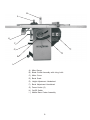
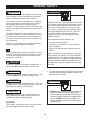
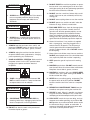
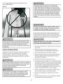
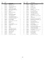
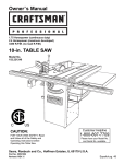
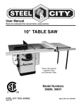
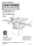
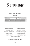
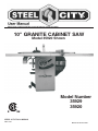
R
10" GRANITE CABINET SAW
Model 35920 Shown
Model Number
35929
35920
STEEL CITY TOOL WORKS
VER. 12.08
Manual Part No. SC75009
TABLE OF CONTENTS
INTRODUCTION
SECTION 1
Warranty ........................................................................................................................................4
SECTION 2
Product Specifications ...................................................................................................................7
SECTION 3
Accessories and Attachments ........................................................................................................8
SECTION 4
Definition of Terms..........................................................................................................................8
SECTION 5
Feature Identification .....................................................................................................................9
SECTION 6
General Safety..............................................................................................................................10
SECTION 7
Product Safety .............................................................................................................................12
SECTION 8
Electrical Requirements................................................................................................................13
SECTION 9
Grounding Instructions .................................................................................................................14
SECTION 10 Unpacking & Inventory..................................................................................................................15
SECTION 11 Assembly .....................................................................................................................................17
SECTION 12 Adjustments..................................................................................................................................24
SECTION 13 Operations ...................................................................................................................................29
SECTION 14 Maintenance ................................................................................................................................34
SECTION 15 Troubleshooting Guide..................................................................................................................35
SECTION 16 Parts ...........................................................................................................................................36
INTRODUCTION
This user manual is intended for use by anyone working with this machine. It should be kept available
for immediate reference so that all operations can be performed with maximum efficiency and safety.
Do not attempt to perform maintenance or operate this machine until you have read and understand the
information contained in this manual.
The drawings, illustrations, photographs, and specifications in this user manual represent your machine
at time of print. However, changes may be made to your machine or this manual at any time with no
obligation to Steel City Tool Works.
3
Model No. 35929
Model No. 35920
Motor
Induction
Induction
HP
1.75
1.75
Amps
15 / 7.5
15 / 7.5
Volts
120 / 240
120 / 240
Hertz
60
60
RPM
3450
3450
Blade Tilt
Left
Left
Blade Drive
Poly-V Belt
Poly-V Belt
Blade Diameter
10-in
10-in
Blade Arbor
5/8-in
5/8-in
Number of Teeth
40
40
Blade Speed
3450
3450
Max Depth of Cut at 90°
3-3/8-in
3-3/8-in
Max Depth of Cut at 45
2-1/4-in
2-1/4-in
Table in front of blade
At max Depth of Cut
Max Dado Width
12-1/2-in
12-1/2-in
13/16-in
13/16-in
Extension Wings
12-in Granite(2)
12-in Granite(2)
40"
27"
37"
403lb
40"
27"
37"
437.6lb
PRODUCT DIMENSIONS
Length
Width
Height
Net Weight
SHIPPING DIMENSIONS:
Length
30"
38"
Width
29.5"
29.5"
Height
42.7"
42.7"
Gross Weight
430lb
469.5lb
7
ACCESSORIES AND ATTACHMENTS
There are a variety of accessories available for your Steel City Product. For more information on
any accessories associated with this and other machines, please contact your nearest Steel City
distributor, or visit our website at : www.steelcitytoolworks.com.
DEFINITION OF TERMS
Kerf – The material removed from the workpiece by the
blade during any cutting operation.
Anti-Kickback Fingers – A safety device attached to
the blade guard and splitter assembly designed to
minimize the chance of a workpiece being thrown back
during a cutting operation.
Kickback – When the workpiece is thrown back toward
the operator at a high rate of speed during a cutting
operation.
Arbor – The shaft on which the blade or accessory
cutting-tool is mounted.
Riving Knife-The same as splitter-it prevents the slot
cut into kerf from closing behind the blade on a rip. Also
the clearance between riving knife and blade will be
consistent when raising or lowing blade.
Bevel Cut – The operation of making any cut with the
blade set at an angle other than 90 degrees.
Compound Cut – The operation of making both a bevel
and a miter cut at one time.
Miter Cut – The operation of making a cut using the
miter gauge at any angle other than zero degrees.
Crosscut – The operation of making a cut across the
grain or width of a workpiece.
Push Stick – An accessory device that can be made or
purchased to help push the workpiece through the
blade. A push stick is used to keep the operator hands
away from the blade when ripping a narrow workpiece.
Dado – A non-through cut that produces a square notch.
A dado is typically from 1/8-in. to 13/16-in. wide. A dado
requires a special set of blades, not included with this
table saw.
Rabbet – A square notch in the edge of the workpiece.
Featherboard – An accessory device that can be made
or purchased to help guide or hold down a workpiece
during cutting operations.
Rip Cut – The operation of making a cut with the grain
or down the length of the workpiece.
Saw Blade Path – The area that is directly in line with
the blade, including area over, under, behind and in front
of it.
Freehand – A very dangerous operation of making a cut
without using the fence or miter gauge in a cutting
operation. FREEHAND CUTS MUST NEVER BE
PERFORMED ON A TABLE SAW.
Set of the Saw Blade – The distance that the tips of the
saw blade are angled outwards from the thickness of the
blade.
Gum, Pitch or Resin – A sticky, sap based residue that
comes from wood products.
Table/Work Area – The total surface of the top of the
table saw on which the workpiece rests while set-up or
cutting operations are being performed.
Heeling – The misalignment of the blade to the miter
slots; when the blade is not parallel to the miter slots.
8
B
A
H
F
C
G
D
E
I
A) Miter Gauge
B) Blade Guard Assembly with riving knife
C) Motor Cover
D) Bevel Scale
E) Height Adjustment Handwheel
F) Bevel Adjustment Handwheel
G) Fence Hooks (2)
H) On/Off Switch
I ) Mobile Base Caster Assembly
9
GENERAL SAFETY
!
!
WARNING
WARNING
TO AVOID serious injury and damage to the machine,
read and follow all Safety and Operating Instructions
before assembling and operating this machine.
This manual is not totally comprehensive. It does not
and can not convey every possible safety and operational problem which may arise while using this
machine. The manual will cover many of the basic and
specific safety procedures needed in an industrial environment.
Exposure to the dust created by power sanding, sawing, grinding, drilling and other construction activities
may cause serious and permanent respiratory or
other injury, including silicosis (a serious lung disease), cancer, and death. Avoid breathing the dust,
and avoid prolonged contact with dust. The dust
may contain chemicals known to the State of
California to cause cancer, birth defects or other
reproductive harm.
All federal and state laws and any regulations having
jurisdiction covering the safety requirements for use of
this machine take precedence over the statements in
this manual. Users of this machine must adhere to all
such regulations.
Some examples of these chemicals are:
• Lead from lead-based paints.
• Crystalline silica from bricks, cement and other
masonry products.
• Arsenic and chromium from chemically-treated
lumber.
Below is a list of symbols that are used to attract your
attention to possible dangerous conditions.
!
This is the international safety alert symbol. It is used
to alert you to potential personal injury hazards. Obey
all safety messages that follow this symbol to avoid
possible injury or death.
!
Always operate tool in well ventilated area and provide for proper dust removal. Use a dust collection
system along with an air filtration system whenever
possible. Always use properly fitting NIOSH/OSHA
approved respiratory protection appropriate for the
dust exposure, and wash exposed areas with soap
and water.
DANGER
Indicates an imminently hazardous situation which, if
not avoided, WILL result in death or serious injury.
!
1. To avoid serious injury and damage to the machine,
read the entire User Manual before assembly and
operation of this machine.
WARNING
Indicates a potentially hazardous situation which, if not
avoided, COULD result in death or serious injury.
!
CAUTION
!
WARNING
Indicates a potentially hazardous situation, if not avoided, MAY result in minor or moderate injury. It may also
be used to alert against unsafe practices.
2. ALWAYS wear eye protection. Any machine can
throw debris into the eyes during operations,
which could cause severe and permanent eye
damage. Everyday eyeglasses are NOT safety
glasses. ALWAYS wear Safety Goggles (that
comply with ANSI standard Z87.1) when operating power tools.
CAUTION
CAUTION used without the safety alert symbol indicates a potentially hazardous situation which, if not
avoided, may result in property damage.
NOTICE
This symbol is used to alert the user to useful information about proper operation of the machine.
10
!
11. DO NOT FORCE the machine to perform an operation for which it was not designed. It will do a safer
and higher quality job by only performing operations
for which the machine was intended.
WARNING
12. DO NOT stand on a machine. Serious injury could
result if it tips over or you accidentally contact any
moving part.
3. ALWAYS wear hearing protection. Plain cotton is
not an acceptable protective device. Hearing
equipment should comply with ANSI S3.19
Standards.
!
13. DO NOT store anything above or near the machine.
14. DO NOT operate any machine or tool if under the
influence of drugs, alcohol, or medication.
WARNING
15. EACH AND EVERY time, check for damaged parts
prior to using any machine. Carefully check all
guards to see that they operate properly, are not
damaged, and perform their intended functions.
Check for alignment, binding or breakage of all
moving parts. Any guard or other part that is damaged should be immediately repaired or replaced.
4. ALWAYS wear a NIOSH/OSHA approved dust
mask to prevent inhaling dangerous dust or airborne particles.
16. Ground all machines. If any machine is supplied
with a 3-prong plug, it must be plugged into a 3contact electrical receptacle. The third prong is
used to ground the tool and provide protection
against accidental electric shock. DO NOT remove
the third prong.
5. ALWAYS keep the work area clean, well lit, and
organized. DO NOT work in an area that has slippery floor surfaces from debris, grease, and wax.
6. ALWAYS unplug the machine from the electrical
receptacle before making adjustments, changing
parts or performing any maintenance.
17. Keep visitors and children away from any machine.
DO NOT permit people to be in the immediate work
area, especially when the machine is operating.
7. AVOID ACCIDENTAL STARTING. Make sure that
the power switch is in the “OFF” position before
plugging in the power cord to the electrical
receptacle.
!
18. KEEP protective guards in place and in working
order.
19. MAINTAIN your balance. DO NOT extend yourself
over the tool. Wear oil resistant rubber soled shoes.
Keep floor clear of debris, grease, and wax.
WARNING
20. MAINTAIN all machines with care. ALWAYS KEEP
machine clean and in good working order. KEEP all
blades and tool bits sharp.
21. NEVER leave a machine running, unattended. Turn
the power switch to the OFF position. DO NOT
leave the machine until it has come to a complete
stop.
8. AVOID a dangerous working environment. DO
NOT use electrical tools in a damp environment
or expose them to rain or moisture.
!
22. REMOVE ALL MAINTENANCE TOOLS from the
immediate area prior to turning the machine ON.
WARNING
23. SECURE all work. When it is possible, use clamps
or jigs to secure the workpiece. This is safer than
attempting to hold the workpiece with your hands.
24. STAY ALERT, watch what you are doing, and use
common sense when operating any machine. DO
NOT operate any machine tool while tired or under
the influence of drugs, alcohol, or medication. A
moment of inattention while operating power tools
may result in serious personal injury.
9. CHILDPROOF THE WORKSHOP AREA by
removing switch keys, unplugging tools from the
electrical receptacles, and using padlocks.
10. DO NOT use electrical tools in the presence of
flammable liquids or gasses.
11
29. Information regarding the safe and proper operation
of this tool is also available from the following
sources:
25. USE ONLY recommended accessories. Use of
incorrect or improper accessories could cause serious injury to the operator and cause damage to the
machine. If in doubt, DO NOT use it.
Power Tool Institute
1300 Summer Avenue
Cleveland, OH 44115-2851
www.powertoolinstitute.org
26. THE USE of extension cords is not recommended
for 230V equipment. It is better to arrange the
placement of your equipment and the installed
wiring to eliminate the need for an extension cord.
If an extension cord is necessary, refer to the chart
in the Grounding Instructions section to determine
the minimum gauge for the extension cord. The
extension cord must also contain a ground wire and
plug pin.
National Safety Council
1121 Spring Lake Drive
Itasca, IL 60143-3201
American National Standards Institute
25West 43rd. St, 4th Floor
New York, NY. 10036
ANSI 01.1 Safety Requirements
For Woodworking Machines
WWW.ANSI.ORG
27. Wear proper clothing, DO NOT wear loose clothing,
gloves, neckties, or jewelry. These items can get
caught in the machine during operations and pull
the operator into the moving parts. Users must
wear a protective cover on their hair, if the hair is
long, to prevent it from contacting any moving parts.
U.S. Department of Labor Regulations
OSHA 1910.213 Regulations
WWW.OSHA.GOV
28. SAVE these instructions and refer to them frequently and use them to instruct other users.
PRODUCT SAFETY
6. Safety decals are on this machine to warn and
direct you to how to protect yourself or visitors from
personal injury. These decals MUST be maintained
so that they are legible. REPLACE decals that are
not legible.
1. Serious personal injury may occur if normal safety
precautions are overlooked or ignored. Accidents
are frequently caused by lack of familiarity or failure
to pay attention. Obtain advice from supervisor,
instructor, or another qualified individual who is
familiar with this machine and its operations.
7. DO NOT leave the unit plugged into the electrical
outlet. Unplug the unit from the outlet when not in
use and before servicing, performing maintenance
tasks, or cleaning.
2. Every work area is different. Always consider safety first, as it applies to your work area. Use this
machine with respect and caution. Failure to do so
could result in serious personal injury and damage
to the machine.
8. ALWAYS turn the power switch “OFF” before
unplugging the table saw.
3. Prevent electrical shock. Follow all electrical and
safety codes, including the National Electrical Code
(NEC) and the Occupational Safety and Health
Regulations (OSHA). All electrical connections and
wiring should be made by qualified personnel only.
!
!
WARNING
WARNING
9. DO NOT handle the plug or table saw with
wet hands.
10. USE accessories only recommended by Steel City.
11. DO NOT pull the table saw by the power cord.
NEVER allow the power cord to come in contact
with sharp edges, hot surfaces, oil or grease.
4. TO REDUCE the risk of electrical shock. DO
NOT use this machine outdoors. DO NOT
expose to rain or moisture. Store indoors in a
dry area.
12. DO NOT unplug the table saw by pulling on the
power cord. ALWAYS grasp the plug, not the cord.
5. STOP using this machine, if at any time you experience difficulties in performing any operation.
Contact your supervisor, instructor or machine
service center immediately.
12
13. REPLACE a damaged cord immediately. DO NOT
use a damaged cord or plug. DO NOT USE if the
table saw is not operating properly, or has been
damaged, left outdoors or has been in contact with
water.
22. DO NOT use the rip fence as a guide when cross
cutting.
14. DO NOT use near or around children.
15. ENSURE that the machine sits firmly on the floor
before using. If the machine wobbles or is unstable,
correct the problem by using shims or blocks prior to
operation.
23. BE MINDFUL of flaws in the wood. Cutting a warped
or twisted board along the rip fence can get pinched
between the fence and the blade, causing a kickback.
24. ALWAYS remove cut off pieces and scraps from the
table before starting the saw.
16. KEEP saw blade sharp and clean. Failure to do so
greatly increases friction, decreases cut quality, and
increases the possibility of a kickback.
25. NEVER start the machine with the workpiece against
the blade.
17. MAKE CERTAIN the saw blade is parallel with the
miter slots and with the rip fence. A blade that is not
aligned parallel can cause the workpiece to be
pinched between the blade and the fence causing
burning or kickbacks.
26. NEVER perform freehand operations. Use either the
fence or miter gauge to position and guide the
workpiece through the blade.
27. ALWAYS use a pushstick for ripping narrow
workpieces.
18. ALWAYS use blade guard on all through cuts. This
will help prevent the cut from closing on the back of
the saw blade. The blade guard also has antikickback fingers which minimize the chance of a
workpiece being thrown back during a cutting
operation.
28. NEVER have any part of your body in line with the
path of the saw blade. If a kickback occurs with you
directly in front of the blade, a serious injury can
occur.
19. ALWAYS push the workpiece past the blade. DO
NOT release a workpiece until it is past the blade
and removed from the saw.
29. NEVER attempt to free a stalled blade with out first
turning the machine off and disconnecting the saw
from the power source.
20. DO NOT execute a cut when you do not have
complete control of the situation.
30. DO NOT reach over or behind a rotating saw blade.
21. DO NOT cut a workpiece that is too large for you to
safely handle. Use an outfeed table or workstand to
properly support the piece.
ration of your 240V outlet. Please follow the instruction of
wiring diagram for changing the motor Voltage from 120
Volt to 240 Volt.
This manual is written for two specific models, Model No
35929,35920. Please follow the specific requirements for
your model saw.
The switch provided with your saw is a dual voltage
capable switch, meaning it is designed to function at
either 120 or 240 volts. The switch and saw comes prewired for 120 volt operation. If you decide to convert the
saw to 240V, you will have to replace the 120 volt plug on
the switch with a UL/CSA Listed plug, suitable for 240
volts. The table saw with a 240 volt plug should only be
connected to an outlet having the same configu-
13
In the event of a malfunction or breakdown, GROUNDING provides the path of least resistance for electric
current and reduces the risk of electric shock. The plug
MUST be plugged into a matching electrical receptacle
that is properly installed and grounded in accordance
With ALL local codes and ordinances.
The smaller the gauge-number, the larger the diameter
of the extension cord is. If in doubt of the proper size of
an extension cord, use a shorter and thicker cord. An
undersized cord will cause a drop in line voltage
resulting in a loss of power and overheating.
If a plug is provided with your machine DO NOT modify
the plug. If it will not fit your electrical receptacle, have a
qualified electrician install the proper connections to
meet all electrical codes local and state. All connections
must also adhere to all of OSHA mandates.
USE ONLY a 3-wire extension cord that has a 3-prong
grounding plug and a 3-pole receptacle that accepts the
machine's plug.
IMPROPER ELECTRICAL CONNECTION of the
equipment-grounding conductor can result in risk of
electric shock. The conductor with the green insulation
(with or without yellow stripes) is the equipmentgrounding conductor. DO NOT connect the equipmentgrounding conductor to a live
If you are using an extension cord outdoors, be sure it is
marked with the suffix " W-A" ( "W" in Canada) to
indicate that it is acceptable for out door use.
Make certain the extension cord is properly sized, and in
good electrical condition. Always replace a worn or
damaged extension cord immediately or have it repaired
by a qualified person before using it.
Check with a qualified electrician or service personnel if
you do not completely understand the grounding
instructions, or if you are not sure the tool is properly
grounded.
Protect your extension cords from sharp objects,
excessive heat, and damp or wet areas.
The motor supplied with your machine is either a
120/240 dual voltage motor or a dedicated 240 volt.
Never connect the green or ground wire to a live
terminal.
The machine should only be connected to an outlet
having the same configuration as the plug.
14
Parts can be cleaned by spraying WD-40 on them and
wiping it off with a soft cloth. This may need redone
sever-al times before all of the protective coatings are
removed completely.
After cleaning, apply a good quality paste wax to any
unpainted surfaces. Make sure to buff out the wax
before assembly.
Compare the items to inventory figures; verify that all
items are accounted for before discarding the shipping
box.
If any parts are missing, do not attempt to plug in the
power cord and turn "ON" the machine. The machine
should only be turned "ON" after all the parts have
been obtained and installed correctly. For missing parts,
contact Steel City at 1-877-SC4-TOOL.
Remove any protective materials and coatings from all
of the parts and the table saw. The protective coatings
can be removed by spraying WD-40.
Check shipping carton and machine for damage before
unpackaging. Carefully remove packaging materials,
parts and machine from shipping carton. Always check
for and remove protective shipping materials around
motors and moving parts. Lay out all parts on a clean
work surface.
A) Blade Guard and Splitter Assembly
B) Mobile Base Caster Assembly
C) Miter Gauge
D) Blade Wrench
E) Blade Wrench
F) Riving Knife (2)
G) Cabinet Wheels (2)
H) Dust Port
I) Handwheel Assembly(2)
J) Handwheel Lock Knob(2)
A
B
C
G
I
F E
J
D
H
15
AA)
1/4-20x1/2" ROUND HD TAP SCREW (4) for
dust chute
16
AB)
M4x8mm ROUND HD TAP SCREW (2)
AC)
WRENCH HOOK
AD)
1/4-20x3/8"ROUND HD TAP SCREW (4)
AE)
FENCE BRACKET (2)
AM)
GRANITE EXTENSION WING
AN)
Support Bar(2)
AO)
M8x20mm HEX SOC SET SCREW (4)
AP)
5/16-18 HEX NUT (3)
AQ)
M8 LOCK WASHER (3)
AR)
M8 FLAT WASHER (3)
AS)
5/16-18x2" HEX SOC SET SCREW (3)
HANDWHEEL ASSEMBLY
• The table saw is a heavy machine; two people may be
required for certain assembly operations.
• DO NOT assemble the table saw until you are sure the
tool is unplugged.
• DO NOT assemble the table saw until you are sure the
power switch is in the "OFF" position.
• For your own safety, DO NOT connect the machine to
the power source until the machine is completely
assembled and you read and understand this entire
User Manual.
Fig. 2
B
C
INSTALLATION AND LEVELING
Final location for the saw must be level, dry, well lighted,
and have enough room to allow movement around the
saw with long pieces of wood stock.
A
Level the saw front to back and side to side. If necessary,
but make sure the saw is stable before being placed in to
service.
1. Place one of the handwheels (A) onto the blade
raise/lower shaft (B) located on the front of the
cabinet. Align the groove in the back of the
handwheel with the pin (C). SEE FIG 2.
DUST PORT ASSEMBLY
Fig. 3
Fig. 1
D
2. Thread the locking knob (D) onto the threaded end of
the shaft. SEE FIG 3.
1. Attach the dust port to the opening in the bottom rear
of the cabinet with four 1/4-20x1/2" SEE FIG.1.
3. Repeat the steps above to assemble the remaining
handwheel and locking knob onto the bevel shaft
located on the side of the cabinet.
17
WRENCH AND FENCE HOOK
ASSEMBLY
Fig. 5
Fig. 4
A
B
C
Fig. 6
1. Assemble both of the fence hooks (A) to the left side
of the cabinet (B) using four 1/4-20x3/8" (4) round
head screws.
2. Assemble wrench hook (C) to the left side of cabinet
(B) using (2) 1/4-20x3/8” round head screws.
SEE FIG 4.
POLY-V BELT ASSEMBLY
1. Loosen 4 of M4x8mm pan head tap screws (D) and
remove the cabinet access door. SEE FIG 5.
2. Install the belt on the Arbor Pulley and raise motor /
motor mounting bracket to reach the belt distance
for assembling the belt on motor pulley.
3. Using a straight edge, check both pulleys to make
sure they are parallel. SEE FIG 6.
4. If not, loosen 4 of the motor mounting screws (A) for
adjustment and tighten the fastening screws.
5. Replace the cabinet access door.
18
Fig.9
GRANITE EXTENSION WING ASSEMBLY
CAUTION: The granite extension wing is heavy; two
people are required for assemble.
1. Install 2 T supporting bars (A) into the T-slot under
main table. SEE FIG 7. Make sure the support bar is
installed all the way into the slot, under the main table.
5. Install 4 of M8x20 Hex Soc Set Screws on both of
the T-supporting bars. SEE FIG 10.
2. Thread the (3) 5/16-18x2” hex soc. Set screws (B) into
the edge of the granite table.
Fig. 10
Fig. 7
6. Use a straight edge across to the main table and
extension wing, checking the flatness of both main
and extension table. SEE FIG 11.
3. Find some help for lifting the extension table. Line up
both slots with the support bar until the extension table
reaches the main table. Make sure the (3)5/16-18x2"
screws protrude into the extension wing to allow the
fastening of the hex nut as shown in FIG. 9.
7. Use a 4 mm Allen wrench to adjust the setting screw
to raise or lower the extension wing to the table.
Fig. 11
Fig. 8
8. Using a 13 mm wrench secure the 5/16-18 hex nut
in FIG. 9.
9. Check the flatness of the table and extension wing
with a straight edge. Make sure both tables are the
same level. If not, refer to step 7 and 8 until completely
Adjusted.
4. Install the both M8 Flat & lock washers and secure
the 5/16-18 hex nut. Do not tighten until the wing is
Level.
19
Fig. 13
RIVING KNIFE COMPONENTS
ASSEMBLY
Note: Remove the table insert retaining bolt used to
secure the table insert (A) to the saw table. SEE FIG 12.
Fig. 12
Fig. 14
INSTALLING AND REMOVING
THE RIVING KNIFE
1. Line up the riving knife in the proper direction to the
mounting bracket (B). SEE FIG13.
2. Push the Riving Knife all the way down into the
mounting bracket, make sure the lock pin is properly
locked in the hole of the Riving Knife. (The lock hole is
on the button side of the Riving Knife).
BLADE ASSEMBLY
3. If it is not locked properly, hold the fasten knob (C)
and pull the lock pin off and make sure the lock pin is
properly located at the hole of Riving Knife. While
raising or lowering the knife, pin will snap in the hole
of the knife when located properly. SEE FIG13.
Fig. 15
4. Tighten the fasting knob.(C)
•Remove
1.Loosen the fasten knob (C).
2.Hold the knob and pull the locking pin out.
3.Remove the Riving Knife out of mounting bracket.
NOTE: Make sure blade or arbor is at the highest
position before adding or removing the riving knife.
20
5. Replace the table insert and tighten the table insert
retaining bolt removed instep 1.
1. Remove the hex nut (K) and outer flange (J) from the
blade arbor (I). Note: The arbor has a right hand
thread; to loosen the hex nut turn it counterclockwise.
6. Always check the blade guard and anti-kickback
fingers before using the saw to make sure they
operate freely and don't bind.
2. Place a 10" saw blade (Z) onto the blade arbor (I),
make sure the teeth of the blade are pointing down in
the front of the table saw. Place the outer flange (J)
and hex nut (K) onto the blade arbor and snug hex
nut by hand. Place the open-end blade wrench (L) on
the flats of the inner blade flange (not shown) and
the box-end blade wrench (M) onto the hex nut and
securely tighten.
Note: The blade arbor has a right hand thread, to
tighten the hex nut turn it clockwise. SEE FIG.15
Riving knife to blade adjustment
1. Riving knife to blade clearance: the gap between
The riving knife and the saw blade should be an even
distance across the entire radius. SEE FIG 18.
Fig. 18
Fig. 16
2. The riving knife should also be in line with the saw
blade. If adjustment is necessary:
1) Locate the riving knife clamping block assembly.
SEE FIG.21
3. Place a square (N) onto the saw blade and against the
splitter assembly (O). Make sure the splitter is square
to table. SEE FIG.16
2) Loosen the (2) 5 MM Socket head cap screws slightly
enough to move the bracket bringing the riving knife in
line with the saw blade making sure the gap between
the blade and knife is even and from 1/4 to 5/16“ in
Distance.
4. Lay a straight edge (R) against the left side of the saw
blade (S) Align the splitter and make sure the
splitter is aligned to the blade. Note: the riving knife
alignment is set at the factory. You should not need
any further adjustment. If it is necessary please refer
to the Riving knife to blade adjustment section.
SEE FIG.17
3) Once the riving knife is aligned with the blade, tighten
the (2) 5 mm Socket head cap screws up.
Fig. 19
Fig. 17
21
To tilt the blade bevel to 45-degrees, loosen the handwheel lock knob (counterclockwise) and turn the handwheel clockwise. When the saw blade is at 45-degrees it
will come into contact with the adjustable positive stop
which will cause the blade to stop. Tighten the hand-wheel
lock knob (clockwise) until it is securely tightened.
RAISING AND LOWERING THE BLADE
Fig. 20
B
ADJUSTING BLADE BEVEL
POSITIVE STOPS
Fig. 21
A
The blade height adjustment handwheel and
handwheel lock knob are located on the front of
the cabinet above the blade bevel scale. To
raise the saw blade, loosen the handwheel lock
knob (A) (counterclockwise) and turn the
handwheel (B) clockwise. When the saw blade
is at its desired height, tighten the handwheel
lock knob (clockwise) until it is secuely
tightened. SEE FIG 20
1. To adjust blade to a 90-degree blade bevel positive
stop, raise the saw blade (A) to its highest position.
SEE FIG 21
To lower the saw blade, loosen the handwheel
lock knob (counterclockwise) and turn the
handwheel counterclockwise. When the saw
blade is at its desired height, tighten the
handwheel lock knob (clockwise) until it is
securely tightened.
2. Using a combination square (B) check that the blade is
90 degrees to the saw table (zero degrees on bevel
scale).
3. If the blade will not tilt to 90 degrees, turn (counterclockwise) the set screw in the left miter slot of the saw
table until the blade can be positioned to 90 degrees.
TILTING THE BLADE
4. Once the blade has been tilted to 90 degrees (confirm
this using your square), tighten the bevel handwheel
lock knob, located on the side of the cabinet. This will
keep the blade from tilting further.
The blade bevel handwheel and handwheel lock knob are
located on the left side of the cabinet. To increase the
saw blade bevel, loosen the handwheel lock knob
(counterclockwise) and turn the hand wheel clockwise.
When the saw blade is at its desired degree, tighten the
handwheel lock knob (clockwise) until it is securely
tightened.
To return the saw blade bevel to zero degrees, loosen
the handwheel lock knob (counterclockwise) and turn the
handwheel counterclockwise. When the saw blade is
back to zero degrees it will come into contact with the
adjustable positive stop which will cause the blade to
stop. Tighten the handwheel lock knob (clockwise) until it
is securely tightened.
5. Turn the set screw (clockwise) until it comes in contact
with the positive stop.
6. Loosen the bevel handwheel lock knob located on the
side of the cabinet, and rotate bevel handwheel until
the blade is at 45 degrees to the saw table.
7. If the blade will not tilt to 45 degrees, turn (counterclockwise) the set screw located just to the right of the
right miter slot, until the blade can be positioned to 45
Degrees.
22
Fig. 22
1. Raise the saw blade to its highest point.
2. Place a combination square (A) on the saw table with
one edge (B) of the square against the left miter slot
(C). SEE FIG 23.
3. Adjust the square so the rule (D) just touches the saw
blade. Make sure the rule is not touching any of the
carbide tips of the saw blade.
4. Lock the rule in this position.
Fig. 24
8. Using a combination square (C), make sure that the
blade is at 45 degrees. SEE FIG 22
9. With the blade at 45 degrees, tighten the bevel
handwheel lock knob to keep the blade from further
tilting.
10.Turn the set screw clockwise until it comes in contact
with the positive stop.
CHECKING BLADE ALIGNMENT
Blade heel is the misalignment of the blade to the miter
slots. This means that the blade is not parallel to the
miter slots. The blade is set parallel at the factory and
should not need any adjustments. You can check this by
using a dial indicator (not included) or a combination
square (not included). It is recommended to check the
alignment before initial operation as follows:
6. Rotate the saw blade back so that you take the
measurement from the same spot on the saw blade.
SEE FIG 24
7. Take a reading at the rear of the blade (E) with the
combination square. If there is a difference of more
than. 01 in between the rule and the blade, then an
adjustment will have to be made.
8. If an adjustment is necessary, see "ADJUSTING
BLADE ALIGNMENT"
Fig. 23
ADJUSTING BLADE ALIGNMENT
NOTICE: Blade alignment is factory set and should not
need adjustment. All saw blades have some runout.
Therefore, readjusting the blade alignment should only be
attempted if it becomes necessary (see "CHECKING
BLADE ALIGNMENT")
23
BEVEL ARROW ADJUSTMENT
Fig. 25
1. Make certain that the blade is at 90-degrees to the
Table surface with a combination square.
Fig. 27
1. To align the blade parallel to the miter slot, first loosen
two hex head screws (A) under the left side of the
table saw. This is the same side as the bevel
handwheel (B).SEE FIG 25.
2. Check that the bevel arrow is pointing to the zero
degree mark on the bevel scale located on the front
of the cabinet. SEE FIG 27.
Fig. 26
3. To adjust arrow, loosen the Philips head screw (A),
and reposition the bevel arrow and tighten screw.
CHANGING THE SAW BLADE
Fig. 28
2. Open motor cover located on the right side of the
table saw. Loosen two hex head screws (C) located
directly above the opening. SEE FIG 26.
3. The saw table is now loose and can be repositioned
until the blade is parallel to the miter slot. Repeat
steps in "CHECKING BLADE ALIGNMENT."
4. When blade is parallel to miter slot, tighten all four
hex head screws.
5. Recheck blade alignment.
6. Tilt the blade to 45 degrees, and rotate the saw blade
by hand. Make sure the blade does not contact the
table insert.
1. Remove the table insert retaining bolt and remove the
Table insert.
24
2. Remove blade guard, splitter and riving knife.
NOTE: can not insert the blade guard after the table
insert is attached.
1. The table insert (A) must always be level with the saw
table (B). To adjust the table insert, loosen and remove
table insert retaining bolt (C). SEE FIG29.
3. Unlock the height adjustment handwheel lock and
raise saw blade to maximum height.
2. Place a straight edge across the front and rear of the
table insert. Check that the insert is perfectly level with
the saw table.
4. Two wrenches are supplied with the table saw. Place
one open-end wrench (A) on the flat of the saw arbor
to keep it from turning. Place the closed-end wrench
(B) on the arbor nut (C). Turn the arbor nut wrench
toward the back of saw to loosen it. Remove arbor
nut, blade flange (D) and saw blade (E).
SEE FIG 28. Page 22.
3. To level the table insert, turn the one or more adjusting
set screws (D) as needed and recheck.
4. Once the insert is level, secure the insert with the
retaining bolt removed instep 1.
5. The table insert is equipped with a finger hole (E) for
Easy removal.
5. Assemble the new saw blade; make certain the teeth
point down at the front of the saw table and assemble
the blade flange and arbor nut. Using both blade
wrenches as previously mentioned, tighten arbor nut in
the opposite direction from which it was loosened.
CHANGING MOTOR VOLTAGE
6. Replace blade guard, splitter and riving knife.
7. Replace table insert and tighten the table insert
Retaining bolt.
TABLE INSERT ADJUSTMENT
The motor supplied with the table saw is a dual voltage
120/240-volt, single phase motor. The motor is wired from
the factory for 120-volt operation. To change to 240-volt
operation for your table saw, proceed with the following
instructions. It is also necessary to replace the 120 volt
plug, supplied with the table saw, with a UL/CSA Listed
plug (not included) suitable for 240 volts and the rated
current of the motor. The table saw with a 240 volt plug
should only be connected to an outlet having the same
configuration as the plug. No adapter is available or
should be used with the 240 volt plug.
Fig. 29
Fig. 30
25
1. Make sure the switch is "OFF" and disconnect power
cord from power source.
ADJUSTING POSITIVE STOPS
Fig. 32
2. Open motor cover and verify on the motor tag that
motor is dual voltage.
3. If motor tag states that it is dual voltage remove
junction box cover (A) on motor (B). SEE FIG 30.
4. Using wiring diagram on inside of junction box cover,
reconnect motor leads for 240-volt or refer to page 13
of wiring diagram.
5. Replace junction box cover and close motor cover.
6. Replace the 120-volt plug with a plug rated for
240-volt operation.
7. The ON / OFF switch is 4-pole and does not need
Modified.
MITER GAUGE ADJUSTMENT
1. To adjust 0-degree positive stops, loosen knob (B), pull
out on plunger (C) and turn miter gauge over.
Fig. 31
2. Loosen the lock nut (D) 3 or 4 turns. SEE FIG 32.
3. Place a square against the guide bar and front of the
miter gauge body. Square the miter gauge body to the
guide bar and tighten knob.
4. Push in plunger and make adjustments to stop screw
(E) so that it touches the plunger and tighten lock nut.
5. Recheck the positive stop angle to the saw blade.
insert the guide bar into the miter slot and slide the
miter gauge up to the saw blade.
6. To check, place a square against the saw blade and
miter gauge body. If any more adjustments are needed
repeat steps above.
7. To set both 45-degree positive stops, repeat steps 1
Thru 6 above at the 45-degree settings.
Arbor gib assembly adjustment
1. The miter gauge has adjustable positive stops at 0degree and 45-degrees or it can be manually set at
any angle between 60-degrees.
A dovetail gib is provided on the arbor height assembly to
insure a good sliding fit between the arbor assembly and
the trunnion bracket when raising and lowering the blade.
This gib has been adjusted at the factory and should not
need any further adjustment. If adjustment is necessary,
perform the following steps.
2. To rotate miter gauge body (A), loosen knob (B) and
pull out plunger (C) and rotate miter gauge body to
desired angle and tighten knob. SEE FIG 31
3. To rotate to the next positive stop, pull plunger (C) out,
rotate miter gauge body then push plunger back in and
continue rotating miter gauge body until it stops
Against next positive stop.
26
4
4
5
5
27
5
28
38
38
36
36
37
37
29
39
39
40
40
30
41
41
31
42
42
32
FENCE INSTALL
TO INSTAll RIP FENCE- FOR 35920 ONLY
1. Place the rear clamp (A) under the rear rail of the
saw table and pull slightly toward the front of the unit
2. Lower the front end of the rip fence (B) onto the guide
surface on top of the front rail.
3. Push the locking handle down to automatically align
and secure the fence. When securely locked, the
locking handle should point downward. SEE FIG. 43
Fig. 43
B
A
33
TROUBLESHOOTING GUIDE
This section covers the most common processing problems encountered in sawing and what
to do about them. Do not make any adjustments until the table saw is unplugged and moving
parts have come to a complete stop.
PROBLEM
LIKELY CAUSE(S)
SOLUTION
Saw stops or will
not start.
1.Overload tripped.
2.Saw unplugged from wall or motor.
3.Fuse blown or circuit breaker tripped.
4.Cord damaged.
1.Allow motor to cool and reset by pushing
reset switch.
2.Check all plug connections.
3.Replace fuse or reset circuit breaker.
4.Replace cord.
Does not make
accurate 45°or
90°cuts.
1.Stops not adjusted correctly.
2.Angle pointer not set accurately.
3.Miter gauge out of adjustment.
1.Check blade with square and adjust stops.
2.Check blade with square and adjust pointer.
3.Adjust miter gauge.
Material binds
blade when
ripping.
1.Fence not aligned with blade.
2.Warped wood.
3.Excessive feed rate.
4.Splitter not aligned with blade.
1.Check and adjust fence.
2.Select another piece of wood.
3.Reduce feed rate.
4.Align splitter with blade.
1.Dull blade.
2.Blade mounted backwards.
3.Gum or pitch on blade.
4.Incorrect blade for cut.
5.Gum or pitch on table.
1.Sharpen or replace blade.
2.Turn blade around.
3.Remove blade and clean.
4.Change blade to correct type.
5.Clean table.
Blade does not
come up to
speed.
1.Extension cord too light or too long.
2.Low shop voltage.
3.Motor not wired for correct voltage.
1.Replace with adequate size cord.
2.Contact your local electric company.
3.Refer to motor junction box.
Saw vibrates
excessively.
1.Stand on uneven floor.
2.Damaged saw blade.
3.Bad poly V-belts.
4.Bent pulley.
5.Improper motor mounting.
6.Loose hardware.
7.Loose set screw in pulley.
1.Reposition on flat, level surface.
2.Replace saw blade.
3.Replace poly V-belts.
4.Replace pulley.
5.Check and adjust motor.
6.Tighten hardware.
7.Tighten set screw.
Rip fence binds
on guide tube.
1.Guide rails or extension wing not
properly installed.
2.Guide of rip fence not adjusted properly.
1.Reassemble guide rails, refer to fence
manual.
2.Adjust guides, refer to fence manual.
1.Rip fence out of alignment.
2.Splitter not aligned with blade.
3.Feeding stock without rip fence.
4.Splitter not in place.
5.Dull blade.
6.Letting go of material before it is past
blade.
7.Anti-kickback fingers dull.
1.Align rip fence with miter slot.
2.Align splitter with blade.
3.Install and use rip fence.
4.Install and use splitter (with guard).
5.Replace blade.
6.Push material all the way past blade before
releasing work.
7.Replace or sharpen anti-kickback fingers.
1.Sawdust and debris in raising and tilting
1.Clean and grease.
Saw makes unsatisfactory cut.
Material kicked
back from blade.
Blade does not
raise or tilt
freely.
34
35
KEY
NO.
PART
NO.
DESCRIPTION
1
34
Or91775
M4x15mm PAN HD SCREW
1
PUSH NUT
2
35
OR91082
CURSOR
1
OR91781
BLADE GUARD PIN
1
36
OR91081
PLUNGER BLOCK
1
3
SC10137
"SEE THRU" BLADE GUARD
1
37
OR91080
PLUNGER
1
4
OR91574
WARNING LABEL
1
38
OR90143
M4 FLAT WASHER
2
4A
OR91575
WARNING LABEL PICTORAL
1
39
OR91076
MITER GAGE BODY
1
5
SC80105
M6x32mm HEX HD SCREW
1
40
SC10268
GUIDE BAR
1
6
SC10138
BLADE GUARD SUPPORT ARM
1
41
OR91763
M4x16mm HEX SOC SET SCREW
4
7
OR90235
M6 LOCK NUT
1
42
OR91783
1/4"x3/4" DOWEL PIN
1
8
OR91745
SPRING
1
43
OR91774
M4x10mm PAN HD SCREW
2
9
SC10139
BLADE GUARD BUSHING
2
44
SC10164
TABLE INSERT LEFT PAD
1
10
OR94428
M5 LOCK NUT
1
45
SC10165
TABLE INSERT RIGHT PAD
1
11
SC80103
M5x30mm HEX HD SCREW
1
46
OR91789
1/4-28x3/8" NYLON SET SCREW
5
12
SC10140
ANTI KICKBACK FINGER
2
47
SC10166
TABLE INSERT
1
13
OR91795
4x22mm SPRING PIN
1
48
SC80110
M5X16 SLOTTED CHEESE HD SCREW
3
14
SC10141
3mm BLADE SPLITTER ASSY
1
49
Sc10269
TABLE
1
*
SC10142
SPLITTER MOUNT SUPPORT ASSY
1
50
SC10271
TABLE RUNNER
2
15
SC10143
SPLITTER MOUNT SUPPORT
1
51
SC80301
M6x15mm HEX SOC FLAT HD SCREW
8
16
OR90509
M6 LOCK WASHER
2
52
OR93914
M8x30mmHEX SOC SET SCREW
1
17
OR90529
M6 FLAT WASHER
2
53
SC80603
M8x40mmHEX SOC NYLON SET SCREW
1
18
OR93374
M6x20mm HEX SOC HD SCREW
2
54
OR90145
M5 LOCK WASHER
2
19
SC10144
SPECIAL PIN
1
55
SC10271
TABLE INSERT BRACKET
1
20
SC10145
SPRING
1
56
SC80203
M5x15mm HEX SOC HD SCREW
2
21
OR90077
M4 LOCK WASHER
4
57
SC10270
TABLE RUNNER
2
22
SC80204
M4x20mm HEX SOC HD SCREW
4
58
SC82114
M8 FLAT WASHER (8.3x25x3.5)
4
23
SC10146
SUPPORT PLATE
1
59
OR91663
M8 LOCK WASHER
4
24
SC10147
SCREW
1
60
OR90634
5/16-18x1" HEX HD SCREW
4
25
SC10148
KNOB
1
61
SC10272
RIGHT GRANITE EXTENSION WING 10"
1
26
SC10149
WASHER
1
62
SC10170
EXTENSION WING RUNNER
2
27
SC10150
RIVING KNIFE 2.5mm THICK
1
63
SC10170
EXTENSION WING RUNNER
2
28
SC10151
RIVING KNIFE 3mm THICK
1
64
SC10273
LEFT GRANITE EXTENSION WING 10"
1
*
SC10267
MITER GAUGE ASSY (#29-43)
1
65
OR91659
5/16-18 HEX NUT
6
29
SC10153
MITER GAGE KNOB
1
66
SC80604
5/16-18x2" HEX SOC SET SCREW
6
30
OR91084
SPECIAL WASHER
1
67
OR91663
M8 LOCK WASHER
6
31
OR91573
MITER SCALE
1
68
OR94207
M8 FLAT WASHER
6
32
OR90078
M4 HEX NUT
3
69
SC10173
T ORIENTED BLOCK
4
33
OR94404
M4x20mm PAN HD SCREW
3
70
OR93380
M8x15 HEX SOC SET SCR
8
KEY
NO.
PART
NO.
DESCRIPTION
*
SC10136
BLADE GUARD ASSY
1
OR91785
2
QTY
36
QTY
37
PART
NO.
DESCRIPTION
QTY
KEY
NO.
PART
NO.
DESCRIPTION
200
OR91766
5/8-18 JAM NUT
1
242A
SC84005
SPRING PIN 4x20mm
1
201
OR91020
ARBOR PULLEY
1
242B
SC10194
WORM GEAR
1
202
OR91824
5x5x15mm KEY
1
243
SC10195
ELEVATING SHAFT
1
203A
OR91732
ARBOR SPACER 1.75HP
1
244
OR91795
SPRING PIN 4x22mm
1
203
OR92137
M5x12mm PAN HD SCR
3
251
SC10192
HEX NUT
1
204
OR94851
<60042Z> BALL BEARING
1
245
SC10198
RAISE / LOWER SLEEVE
1
205
SC10181
ARBOR RAISING SUPPORT BRACKET
1
246
SC10193
FRONT TRUNNION
1
205A
SC10189
GIB
1
247
OR93374
M6x20mm HEX SOC HD SCREW
4
205B
OR94541
M5x25mm HEX HD SCREW
2
247A
OR90509
M6 LOCK WASHER
4
205C
OR90799
M5 HEX NUT
2
247B
OR90529
M6 FLAT WASHER
4
206
SC10182
ARBOR SLEEVE
1
248
SC84003
8x30mm SPRING PIN
1
207
SC82701
<6004> WAVE WASHER
1
249
SC10274
CABLE CLAMP
1
208
OR94851
<60042Z> BALL BEARING
1
249A
OR90507
M5x8mm PAN HD SCR
1
209
SC10183
ARBOR SHAFT
1
250
SC10278
MAINT RUNNION
1
210
OR70400
BLADE (OD:10",ID:5/8",TEETH:36)
1
252
SC10199
RAISE/LOWER SPACER
1
211
OR91026
BLADE FLANGE
1
253
SC10200
POINTER
1
212
OR91050
BLADE HEX NUT-RH
1
254
OR90529
M6 FLAT WASHER
1
213
OR91746
M10x45mm HEX HD SCREW
2
255
OR91826
M6x16mm CHEESE HD SCREW
1
214
OR94231
M10 FLAT WASHER
2
256
SC10202
HANDWHEEL
2
215
SC10180
REAR BRACKET
1
256A
SC10275
INSERT HANDLE
2
216
OR94231
M10 FLAT WASHER
2
256C
SC10276
HANDLE SLEEVE
2
217
OR90227
M10 LOCK WASHER
2
258
SC10203
HANDWHEEL LOCK KNOB
2
218
OR90228
M10 HEX NUT
2
259
SC10177
TILT SHAFT ASSEMBLY,(NOTSHOWN)
226
OR90308
SCR HEX HD M8 X 30mm
4
226A
OR94207
M8 FLAT WASHER
4
259A
SC10179
WORM GEAR
1
227
OR94207
M8 FLAT WASHER
4
260
SC84005
SPRING PIN 4x20mm
1
228
SC10196
MOTOR SUPPORT BRACKET
1
261
SC10178
TILT SHAFT
1
229
OR91663
M8 LOCK WASHER
4
261A
OR91795
SPRING PIN 4x22mm
1
230
OR91501
M8 HEX NUT
4
262
OR91738
ECCENTRIC
1
232
OR94417
M8x10mm HEX SOC HD SCREW
1
262A
SC10176
SLEEVE
1
233
SC82113
M8 BIG FLAT WASHER
1
263
SC10277
FRONT BRACKET
1
234
OR91771
1/2-13 LOCK NUT
2
264
OR94231
M10 FLAT WASHER
2
235
SC10197
MOTOR MOUNT STUD
1
265
OR91746
M10x45mm HEX HD SCREW
2
235A
SC10184
WAVE WASHER
1
266
OR91018
TILT COLLAR
1
236
OR70154
MOTOR SPRING
1
266A
SC82702
3/8" FIBER WASHER(t=2mm)
1
237
OR91057
STUD
1
266B
OR91137
COLLAR
1
238
SC10187
ELEVATION PIN
1
266C
OR91762
1/4-20x1/4" HEX SOC SET SCREW
2
239
OR93552
M6x8mm HEX SOC SET SCREW
1
267
OR91816
M6x8mm HEX SOC SET SCREW
2
240
SC10188
ELEVATING BRACKET
1
268
OR90381
M5 HEX NUT
2
240A
SC10184
WAVE WASHER
1
268A
SC82112
M5 FLAT WASHER(5.4x18x3)
2
240B
SC10185
SPECIAL FLAT WASHER
1
269
OR91017
TILT BRACKET
1
240C
SC10186
ELEVATING PIVOT BOLT
1
270
SC80413
M5x25mm ROUND HD SCREW
2
240D
SC80104
M6x10mm HEX HD SCREW
1
274
OR91768
9/16-18 JAM HEX NUT
1
241
OR90308
M8x30mm HEX HD SCREW
2
274A
SC10274
CABLE CLAMP
1
241A
OR91663
M8 LOCK WASHER
2
274B
OR90507
M5x8mm PAN HD SCREW
1
241B
OR94207
M8 FLAT WASHER
2
275
OR94231
M10 FLAT WASHER
2
242
SC10191
ELEVATING SHAFT
276
OR90227
M10 LOCK WASHER
2
277
OR90228
M10 HEX NUT
2
KEY
NO.
ASSEMBLY(#242A,242B,243,244,251)
CONSISTS OF:259A,260,261
1
38
QTY
1
PART
NO.
DESCRIPTION
SC10290
FENCE ASSY ---FOR 35920 ONLY
301
SC10279
LEFT REAR RAIL
301A
SC10280
301B
SC10281
302
SC80112
303
304
KEY
NO.
KEY
NO.
PART
NO.
DESCRIPTION
315
OR94575
CLAMP PAD
2
1
316
OR94576
TENSION CLIP
1
REAR RAIL
2
317
OR90306
M6X12mm PAN HD SCR
1
RIGHT REAR RAIL
1
318
OR91739
E-RING
2
5/16-18*5/8 HEX HD SCR
4
319
OR94577
HANDLE PIVOT SHAFT
1
OR90311
M8 FLAT WASHER
4
320
OR94578
TUBE PLUG
4
OR90248
M8 LOCK WASHER
4
321
OR94579
FENCE LOCK KNOB ASSEMBLY
1
305
SC10282
HOOK
1
322
OR91736
CLAMP CAM
1
306
SC80104
M6X10mm HEX HD SCR
2
326
SC10288
SCALE, LEFT 20" CAPACITY
1
306A
OR90059
M6 FLAT WASHER
2
327
SC10285
LEFT FRONT RAIL
1
306B
OR90502
M6 LOCK WASHER
2
327A
SC10286
RIGHT FRONT RAIL
1
307
SC10283
FENCE WELDING ASSY
1
328
OR94582
CONNECTING CAP
1
308
SC10284
PLASTIC PAD
1
331
SC10289
SCALE, LEFT 20" CAPACITY
1
309
OR91758
M6X15mm HEX HD SCR
2
338
SC10287
FRONT RAIL BRACKET
1
OR91774
M4X10mmPAN HD SCR
4
339
SC80112
5/16-18*5/8 FLAT HD SCR
4
OR90143
M4 FLAT WASHER
4
340
OR90059
M6 FLAT WASHER
8
OR94573
CURSOR
2
341
OR90502
M6 LOCK WASHER
8
313
SC80113
M8X8 SET SCR
2
342
SC80111
M6X16mm HEX SOC HD SCR
8
314
Sc10550
SPECIAL SCREW NYLON
2
300
310
311
312
QTY
39
QTY
401D(4)
401A
401C
420(4)
401
419
401B
424
402
403(3)
427A
429 (4)
427
0
428 (2)
5
10
15
20
25
30
35
40
45
429B(2)
429A(2)
425
405(4)
402B(4)
402A(4)
405A(4)
411
423(3)
426(4)
431
430
409(6)
434(2)
433(2)
421(2)
407
432
439(2)
435
408(3)
438(2)
436
437
440(2)
441(2)
442(2)
40
QTY
KEY
NO.
PART
NO.
DESCRIPTION
CABINET ASS Y WELDMENT
1
*436
OR72922
REAR WHEEL BRACKET
1
SPECIAL LABEL
1
437
OR91503
5/16-18 LOCK NUT
1
BEVEL SCALE
1
438
OR94775
M8x20mm CARRIAGE BOLT
2
CABINET ACCESS DOOR
1
439
OR94771
M8 HEX NUT
2
SC80412
M4x8 ROUND HD TAP SCR
4
440
OR91497
M8x50HEX HD BOLT
2
402
OR70161
HINGE ASSY
1
441
OR90311
M8 FLAT WASHER
2
402A
OR90381
442
OR91505
CASTER WHEEL
2
402B
OR90462
M5 FLAT WASHER
4
*
SC10207
SWITCH ASSY
1
403
OR91787
1/4-20x3/8 ROUND HD TAP SCR
3
404
OR70162
MOTOR COVER
1
443
OR91040
SWITCH PADDLE
404A
SC10212
WARNING LABEL
1
444
SC80411
M4x25mm ROUND HD TAP SCREW
2
404B
SC10215
WARNING LABEL
1
445
SC10208
SWITCH COVER
1
405
OR91777
M5x15mm PAN HD SCR
4
446
OR90343
SWITCH FOR 1.75HP
1
405A
OR90462
M5 FLAT WASHER
4
447
OR91579
SWITCH RESET LABEL
1
406
SC80606
M5x12mm PAN HD SCR
2
448
OR91063
SWITCH BOX
1
406A
SC10292
CLIP
2
449
SC80410
M4x16mm ROUND HD TAP SCREW
4
407
SC10293
CABINET SIDE PANEL
1
450
OR91062
SWITCH SUPPORT
1
408
OR91787
1/4-20x3/8 ROUND HD TAP SCR
3
451
SC80104
M6x10mm HEX HD SCREW
2
409
OR91787
1/4-20x3/8 ROUND HD TAP SCR
6
452
OR90381
M5 HEX NUT
2
411
OR91124
DUST CHUTE ASS'Y WELDMENT
1
453
OR90362
M5 EXT TOOTH WASHER
4
419
OR91128
DUST PORT
1
454
OR90507
M5x8mm PAN HD SCREW
2
420
OR91833
1/4-20x1/2 ROUND HD TAP SCR
4
455
OR70139
RESET SWITCH (25AMP,125/250V)
1
421
OR91132
LEVELING SCREW
2
456
OR91032
JUMPER WIRE (BLACK) 1.75HP
1
423
OR91787
1/4-20x3/8 ROUND HD TAP SCR
3
457
OR91030
POWER CORD
1
424
OR91106
INSULATOR( 7N-2)
1
458
OR70141
STRAIN RELIEF(7P-2)
2
425
OR73521
NAMEPLATE
1
459
SC10438
BELT (6PJ750 L=29.5")
1
426
OR93823
2x8mm RIVIET
4
460
OR90253
M5x12mm HEX SOC SET SCREW
1
427
OR91134
WRENCH HOOK
1
461
OR91023
MOTOR PULLEY 1.75HP
1
427A
OR91832
M4X8mm ROUND HD TAP SCR
2
462
OR91770
5x5x36mm KEY
1
428
OR91135
FENCE BRACKET
2
463
SC72013
MOTOR ASSEMBLY 1.75HP
1
429
OR91787
1/4-20x3/8 ROUND HD TAP SCR
4
464
SC76014
MOTOR SPEC PLATE1.75HP
1
429A
OR91832
M4x8mm TRIANGLE TAP SCREW
2
465
OR91726
7/8"x1/2" WRENCH
1
429B
OR90143
M4 FLAT WASHER
2
466
OR91727
OPEN END WRENCH
1
430
OR91469
FOOT PEDAL
1
467
OR90289
2.5mm ALLEN WRENCH
1
431
OR91502
5/16-18x4mm HEX HD SCR
1
468
OR90290
3mm ALLEN WRENCH
1
432
OR91508
PIN
1
469
OR90291
4mm ALLEN WRENCH
1
433
OR91784
1/2FLAT WASHER
2
470
OR91728
5mm ALLEN WRENCH
1
434
OR91507
EXT. RET. RING1/2"
2
471
OR91729
6mm ALLEN WRENCH
1
435
OR91506
CASTER ASS'Y
1
472
OR91808
1/8" ALLEN WRENCH
1
KEY
NO.
PART
NO.
DESCRIPTION
401
SC10291
401A
SC76025
401B
OR70160
401C
SC10218
401D
'
M5 HEX NUT
4
QTY
(Incl,:#443,444,445,446,447,448,455456)
41
1
42