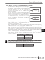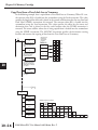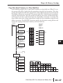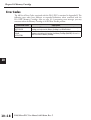
1
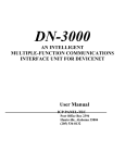
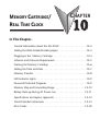
MEMORY CARTRIDGE/
REAL TIME CLOCK
CHAPTER
10
In This Chapter...
General Information about the D0–01MC . . . . . . . . . . . . . . . . . . .10–2
Setting the Write Enable/Disable Jumper . . . . . . . . . . . . . . . . . . . .10–3
Plugging-in the Memory Cartridge . . . . . . . . . . . . . . . . . . . . . . . .10-4
Software and Firmware Requirements . . . . . . . . . . . . . . . . . . . . . .10–5
Naming the Memory Cartridge . . . . . . . . . . . . . . . . . . . . . . . . . . .10–6
Setting the Time and Date . . . . . . . . . . . . . . . . . . . . . . . . . . . . . . .10–7
Memory Transfers . . . . . . . . . . . . . . . . . . . . . . . . . . . . . . . . . . . . .10–8
LED Indicator Lights . . . . . . . . . . . . . . . . . . . . . . . . . . . . . . . . . . . .10–9
Password Protected Programs . . . . . . . . . . . . . . . . . . . . . . . . . . . .10–9
Memory Map and Forwarding Range . . . . . . . . . . . . . . . . . . . . .10–10
Battery Back-up During AC Power Loss . . . . . . . . . . . . . . . . . . . .10–11
Specifications and Agency Approvals . . . . . . . . . . . . . . . . . . . . . .10–12
Clock/Calendar Instructions . . . . . . . . . . . . . . . . . . . . . . . . . . . . .10–13
Error Codes . . . . . . . . . . . . . . . . . . . . . . . . . . . . . . . . . . . . . . . . .10–18
Chapter 10: Memory Cartridge
1 General Information about the D0–01MC
The D0–01MC is a battery-backed RAM memory module with a clock/calendar
function that installs only in the DL05 PLC option slot. The MC backs-up the
2
ladder program and data in CMOS RAM. The on–board lithium battery lasts up to
three years. The module’s V–memory maps one–for–one to the PLC’s memory
3
locations.
When the Memory Cartridge is inserted in the option slot, it automatically
becomes the source of the controlling program. It is also where the program is
4
accessed. You can choose to overwrite the program residing in the PLC via a
pushbutton on the face of the module, but you may chose not to.
5
You can copy the program from the PLC to the MC or from the MC to the PLC or
you can operate directly from the MC. By removing the module, you return control
6
to the PLC’s internal program.
Two pushbuttons on the face of the module initiate memory copies. The pushbuttons
7
are clearly marked to indicate the direction of the copy, and a green LED flashes to
confirm the direction and success of the memory copy.
8
WARNING: The D0–01MC will only work in the DL05 PLC, it will not work in the DL06 PLC.
Jumper Selects Write Enable or Disable
9
A jumper enables/disables the write function in the MC. Write disable prevents overwriting
the MC memory. Write enable allows overwriting the MC memory. See page 10–3 for more
10
information.
Alert
11 Low ABattery
red LED alerts you to a low battery condition. If the battery drops below 2.5V the BATT
LED comes on, and an internal bit is set. You can use the internal bit to activate alarm
12
functions or to execute an orderly shut–down. See page 10–11 for more information.
13 Clock/Calendar
The date and time are easily set or accessed using DirectSOFT, Version 3.0b or later,
programming software. The “year” field contains four digits so it is ready for Y2K and
beyond.
14
Specifications
A
Environmental specifications for the D0–01MC are the same as for the DL05 PLCs. UL and
CE approvals are pending. (Go to www.automationdirect.com for the latest UL and CE
updates.)
See page 10–12 for detailed specifications.
B
New Ladder Instructions
New ladder instructions are available when using the D0–01MC. See page 10–13 for Date
C
and Time instructions. The MOVMC instruction has the ability to use a constant (K value)
when used with the Memory Cartridge.
D
Error Code Changes
Two Error Codes have expanded definitions when using the Memory Cartridge. (See page
10–18).
10–2
DL05 Micro PLC User Manual, 6th Edition, Rev. C
Chapter 10: Memory Cartridge
Setting the Write Enable/Disable Jumper
The position of jumper J1 determines whether or not the Memory Cartridge can be
overwritten. The Write Disable position is used only for transporting a program. With J1 in
the Write Disable position the Memory Cartridge program can be copied to the CPU, but
the PLC cannot be put in RUN mode. The PLC can only be put in the RUN mode with J1
in the Write Enable position. Write failures will generate the E104 Error Code (for more
information see page 10–18).
Write Enable
Set the jumper as shown in Figure 1 if you want the CPU to be able to overwrite the Memory
Cartridge.
The module ships from the factory with
the jumper in the Write Enable position.
Figure 1
This jumper setting allows the
Memory Cartridge to be overwritten.
BATTERY
3V
Write
Enable
J1
Disable
WARNING: Power to the DL05 PLC must be disconnected before inserting or removing the
D0–01MC Memory Cartridge. Failure to disconnect power could result in serious damage to the
module, the PLC or both.
Write Disable
Set the jumper as shown in Figure 2 if you do not want the CPU or DirectSOFT 5 to be able
to overwrite the Memory Cartridge.
Figure 2
This jumper setting prevents the
Memory Cartridge from being
overwritten.
BATTERY
3V
Write
Enable
J1
Disable
DL05 Micro PLC User Manual, 6th Edition, Rev. C
1
2
3
4
5
6
7
8
9
10
11
12
13
14
A
B
C
D
10–3
Chapter 10: Memory Cartridge
1 Plugging-in the Memory Cartridge
Remove the Slot Cover
2
Remove the protective cover from the DL05 option card slot by squeezing the pinch tabs and
lifting the cover off.
3
4
5
6
7
8
9
Insert the Memory Cartridge
10
Insert the D0-01MC module into the open option card slot. The printed markings on the
module should be oriented in the same direction as the markings on the PLC. The female
connector on the printed circuit board of the module will align with the male connector on
11
the PLC mother board. Press the module into the slot until the front of the module is flush
with the front of the PLC.
12
13
14
A
B
C
D
WARNING: Power to the DL05 PLC must be disconnected before inserting or removing the D0Pinch Tabs
Option Card
Slot Cover
01MC Memory Cartridge/Real Time Clock. Failure to disconnect power could result in serious
damage to the module, the PLC or both.
10–4
DL05 Micro PLC User Manual, 6th Edition, Rev. C
Chapter 10: Memory Cartridge
Software and Firmware Requirements
How to Update Your DirectSOFT Programming Software
You will need DirectSOFT 5 Version 5.0 (or later) to use all features of the D0–01MC. If you
have a licensed copy of DirectSOFT, contact AutomationDirect about a software upgrade to
DirectSOFT 5 (PC-DSOFT5).
Your DL05 must have Version 5.10, or later, firmware to operate correctly with all features of
the D0–01MC. To determine your firmware revision level, connect to the DL05 with
DirectSOFT 5 programming software, and click on PLC > Diagnostics > System
Information. This will bring up the System Information screen.
The “CPU Version:” will tell you what firmware revision level is installed in your PLC.
How to Update Your DL05 Firmware
If your DL05 requires new firmware, you may download the latest firmware and upgrade tool
from our website. Point your browser to www.automationdirect.com, and click on Technical
Support. There you will find the latest firmware for the DL05 by going to Downloads, then
Firmware Upgrades. Be sure to download the Koyo Upgrade tool and the Firmware Binary file.
Follow the upgrade instructions contained in the downloaded files. Cycle power after upgrading
the firmware in your DL05 PLC, and DirectSOFT 5 will recognize the new features available
to your PLC.
DL05 Micro PLC User Manual, 6th Edition, Rev. C
1
2
3
4
5
6
7
8
9
10
11
12
13
14
A
B
C
D
10–5
Chapter 10: Memory Cartridge
1 Naming the Memory Cartridge
DirectSOFT 5 allows you to name your Memory Cartridge. Use this feature to identify a
specific machine, a version number for your ladder logic program, etc.
2
3
4
5
6
7
8
Up to 8 Alphanumeric Characters
9
Within DirectSOFT 5, click on PLC/Setup/Memory Cartridge Name to create a name for the
Memory Cartridge. You can use up to 8 alphanumeric or special characters.
10
When you type a name in the “Cartridge Name” field, you
can save the name to disk by clicking on the button with
11
the arrow pointing to the disk, which will store the name
in the DirectSOFT 5 project folder. You can also read the
name from the project folder (if the Memory Cartridge
12
was previously named) by clicking on the button with the
arrow coming from the disk.
13
If the PC is connected to the PLC, the PLC-icon buttons
will become active. When the PLC-icon buttons are active, you can also transfer the name to
14
the PLC or transfer an existing name from the PLC into DirectSOFT 5. Transfering the
Memory Cartridge name into the PLC transfers the name directly to the Memory Cartridge.
A
Name is Retained in Cartridge Memory and Project Folder
Naming the Memory Cartridge is independent of the ladder logic program – although the name
is stored in the DirectSOFT 5 project folder. It is also stored in the battery-backed memory onB
board the Memory Cartridge. Transferring a program from the PLC does not change the name
of the Memory Cartridge even if the program in the PLC originated as a program in another
C
Memory Cartridge that has a different name.
If you require the name of your Memory Cartridge to change, you must change it using the
D
screen shown.
10–6
DL05 Micro PLC User Manual, 6th Edition, Rev. C
Chapter 10: Memory Cartridge
Setting the Time and Date
Use DirectSOFT 5 to set the date and time in your Memory Cartridge, connect to the DL05.
Inside the Project Window, click on PLC/Setup/Calendar to bring up the Calendar window.
NOTE: You can also use ladder instructions to set the date and time. See Clock/Calendar Instructions
beginning on page 10–13.
The first time you view the Calendar window, you will see the factory settings for date and time,
as shown below. You can either change each field individually, or you can click on the “Get PC
Time” button. If you click on the “Get PC Time” button, you will see the values change in all
fields. Note, the values will not continue to update. In order to save this new time, you need to
click on the “Write to PLC” button.
V7766
V7767
V7770
V7771
V7772
V7773
V7774
Seconds
Minutes
Hours
Day of the Week (00=Sun, 01=Mon, etc.)
Day of the Month
Month
Year
2 digits BCD
2 digits BCD
2 digits BCD
2 digits BCD
2 digits BCD
2 digits BCD
4 digits BCD
00 - 59
00 - 59
00 - 23
00 - 06
01 - 31
01 - 12
1970 - 2069
The clock and
c a l e n d a r
functions
are
stored in the
following
Vm e m o r y
locations:
DL05 Micro PLC User Manual, 6th Edition, Rev. C
1
2
3
4
5
6
7
8
9
10
11
12
13
14
A
B
C
D
10–7
Chapter 10: Memory Cartridge
1 Memory Transfers
CPU to MC
2
With system supply power on and the Memory Cartridge installed, put the PLC in STOP
mode. Press and hold the CPU > MC button for about one second, then release. This will
transfer the program from the CPU to the
3
Memory Cartridge. To confirm the transfer,
the associated LED will blink for a few
4
seconds. If the LED does not blink, the
PLC is not in STOP mode. If the LED
5
continues to blink, an error has occurred.
To acknowledge the error, press either of
the two buttons on the face of the
6
module.
7
8
9
NOTE: Memory transfer functions cannot be accessed while the PLC is in RUN mode. Use the toggle
switch on the DL05 to switch the PLC out of RUN mode, or use DirectSOFT 5 programming software
to make the change.
10
11 MC toWithCPU
system supply power on and the Memory Cartridge installed, put the PLC in STOP
mode. Press and hold the CPU < MC button for about one second, then release. This will
12
transfer the program from the Memory Cartridge to the CPU. To confirm the transfer, the
associated LED will blink for a few seconds. If
the LED does not blink, the PLC is not in
13
STOP mode. If the LED continues to
blink, an error has occurred.
14
A
B
C
To acknowledge the error, press either of the
two buttons on the face of the module.
D
10–8
DL05 Micro PLC User Manual, 6th Edition, Rev. C
Chapter 10: Memory Cartridge
LED Indicator Lights
The three indicator lights on the face of the Memory Cartridge perform the following
functions:
LED Indicator
BATT (red)
Condition
Meaning
On
Flashes for several seconds
(150 msec on; 150 msec off)
Does not flash
Flashes continually with
CPU < MC LED steady on
Flashes for several seconds
(150 msec on; 150 msec off)
Does not flash
Flashes continually with
CPU > MC LED steady on
CPU > MC
(green)
CPU < MC
(green)
Replace battery
Successful completion of transfer
No memory transfer: change to STOP mode
Error: press either button to clear
Successful completion of transfer
No memory transfer; change to STOP mode
Error: press either button to clear
Password Protected Programs
Password protected programs cannot be transferred from the CPU on-board memory to the
Memory Cartridge. Also, password protected programs cannot be transferred from the Memory
Cartridge to the CPU on-board memory. Programs can only be transferred in either direction
when a password is not used.
Password
DL05
D0-01MC
PLC Mode
No
No
Yes
No
No
Yes
Yes
Yes
No
No
Yes
No
No
Yes
Yes
Yes
RUN
Program
CPU > MC
CPU < MC
Disable
(No LED ON)
Disable
(No LED ON)
Disable
(No LED ON)
Disable
(No LED ON)
Disable
(No LED ON)
Disable
(No LED ON)
Disable
(No LED ON)
Disable
(No LED ON)
Enable
(> LED blinks)
Enable
(< LED blinks)
Disable
(< LED keeps blinking)
Disable
(> LED keeps blinking)
Disable
(> & < LED keeps blinking)
Disable
(< LED keeps blinking)
Disable
(> LED keeps blinking)
Disable
(> & < LED keeps blinking)
DL05 Micro PLC User Manual, 6th Edition, Rev. C
1
2
3
4
5
6
7
8
9
10
11
12
13
14
A
B
C
D
10–9
Chapter 10: Memory Cartridge
1 Memory Map and Forwarding Range
The Memory Cartridge’s on-board memory maps one-for-one to the DL05 PLC. The memory
types represented in the table below have the same designated locations in either the Memory
2
Cartridge or the DL05 PLC.
Memory Type
Range
3
4
5
6
7
8
9
10
11
12
13
14
A
B
C
D
Program memory
V-memory
System Parameters
10–10
2K (all)
V00000 - V00177 (128 words)
V00200 - V00777 (384 words)
V01000 - V01177 (128 words)
V01200 - V07377 (3200 words)
V07400 - V07577 (128 words)
V07600 - V07777 (128 words)
V40400 - V40417 (16 words)
V40500 - V40517 (16 words)
V40600 - V40637 (32 words)
V41000 - V41017 (16 words)
V41100 - V41107 (8 words)
V41140 - V41147 (8 words)
V41200 - V41237 (32 words)
0.5K (all)
DL05 Micro PLC User Manual, 6th Edition, Rev. C
Chapter 10: Memory Cartridge
Battery Back-up During AC Power Loss
What if the Battery Dies?
In the event of AC power loss to the DL05 PLC, the on-board lithium battery will back-up the
program logic and data values for a period up to three years.
If the Memory Cartridge’s battery voltage drops below
approximately 2.5VDC, the red “BATT” LED will illuminate on
the face of the module. At the same time, the Special Relay SP43 is
set to “1.” You can use this internal bit as a contact in your ladder
program. Use it to trigger an external alarm – indicating that it is
time to change the battery.
SP43
Y0
OUT
During normal operation, the AC power to the PLC will retain the memory in the Memory
Cartridge. If the AC power fails, or is disconnected, a super-capacitor will continue to hold the
memory for 4 to 7 days even if the battery is too weak to hold the memory. Only after the
capacitor has discharged and the battery has become too weak to retain the memory will
program logic and data memory be lost.
Battery Type
When you see the “BATT” indicator light, replace the battery with a CR2032, coin-type 3.0V
lithium battery (Automationdirect.com, part no. D0–MC–BAT). Do you need to change the
battery while retaining the stored program? If the answer is yes, change the battery during the
4 – 7 days that the super-capacitor will retain the program after AC power is disconnected.
NOTE: Be sure your hands are clean and dry before handling the battery. Moisture will corrode the
battery surfaces and shorten the life of the battery.
Installation and
Removing and Replacing the Battery
Push
BATTERY
BATTERY
3V
3V
J1
J1
To remove the battery:
Push the battery in the direction
indicated. You will feel the
battery press against the spring
in the battery socket. Fully
compress the spring and lift the
battery out of the socket.
To replace the battery:
The positive (+) side should be facing
out. The battery should enter the
socket as shown (at about a 30° angle
to the printed circuit board). Push the
battery into the socket until the battery
snaps into place.
DL05 Micro PLC User Manual, 6th Edition, Rev. C
1
2
3
4
5
6
7
8
9
10
11
12
13
14
A
B
C
D
10–11
Chapter 10: Memory Cartridge
1 Specifications and Agency Approvals
Specifications
2
3
4
5
6
7
8
9
10
11
12
13
14
A
B
C
D
Ambient Operating Temperature
Storage Temperature
Ambient Humidity
Atmosphere
Vibration Resistance
Shock Resistance
0 °C to 55 °C (32 °F to 131 °F)
-20 °C to 70 °C (-4°F to 158°F)
5% to 95% non-condensing
No corrosive gases, max. environmental pollution = 2, UL840
MIL STD 810C, method 514.2
MIL STD 810C, method 516.2
Noise Immunity
NEMA ICS3-304
Impulse noise 1µs, 1000V
FCC Class A
RFI (144MHz, 430MHz, 10W, 10cm)
Size
Weight
Battery Number
Battery Type
Battery Life
Battery Voltage
10–12
120mm x 95mm x 65mm
50g
CR2032
(Automationdirect.com part # D0-MC-BAT)
Coin type, 3.0V Lithium Battery, 190mAh
Typ 3 years (at 25°C)
Typ 3.0VDC
Battery Abnormal Voltage
Typ < 2.5VDC
Indication: illuminates red LED and
sets SP43 to "1"
Write Protect
Memory Type
Internal jumper pins
CMOS RAM 32KBytes
Calendar
Frequency accuracy: ±20PPM (25°C)
Temperature characteristic: +10/-20PPM
(0°- 55°C)
Agency Approvals
UL, CE (pending)
DL05 Micro PLC User Manual, 6th Edition, Rev. C
Chapter 10: Memory Cartridge
Clock/Calendar Instructions
Date (DATE)
The Date instruction can be used to set the date in the
Memory Cartridge. The instruction requires two consecutive
V-memory locations (Vaaa) to set the date. If the values in the
specified locations are not valid, the date will not be set. The
current date can be read from four consecutive V-memory
locations (V7771–V7774).
Date
V aaa
V-Memory Location (BCD)
(READ Only)
Range
Year
Month
Day of Month
Day of Week
DATE
1970-2069
1-12
1-31
0-06
V7774
V7773
V7772
V7771
The values entered for the day of week are:
0=Sunday, 1=Monday, 2=Tuesday, 3=Wednesday, 4=Thursday, 5=Friday, 6=Saturday
Operand Data Type
DL05 Range
V-memory
A
aaa
V
All (See page 10-9)
In the following example, when C0 is on, the constant value (K00010301) is loaded into the
accumulator using the Load Double instruction (C0 can be a contact from a one shot (PD)
instruction). The value in the accumulator is output to V2000 using the Out Double
instruction. The Date instruction uses the value in V2000 to set the date in the CPU. The
example loads the date January 3, 2000.
DirectSOFT
C0
K00010301
Load the constant
value (K00010301)
into the accumulator
OUTD
V2000
0
0
1
0
3
0
1
Acc. 0
0
0
1
0
3
0
1
Acc. 0
0
0
1
0
3
0
1
0
0
0
1
0
3
0
1
Copy the value in
the accumulator to
V2000 and V2001
DATE
Constant (K)
0
LDD
V2001
V2000
Format
Set the date in the CPU
using the value in V2000
and V2001
Handheld Programmer Keystrokes
STR
SHFT
L
OUT
SHFT
0
SHFT
3
D
C
0
ENT
0
1
ENT
A
T
E
D
D
D
V2000
V
0
In this example, the Date
instruction uses the value set in
V2000 and V2001 to set the date
in the appropriate V memory
locations (V7771–V7774). The
year is entered as a two digit
number, but it is converted
internally to a four digit number.
Two digit values ranging between
70 – 99 are converted to 1970 –
1999. Values of 00 – 69 are
converted to 2000 – 2069.
V2001
0
Year
K
2
0
1
0
V2000
3
Month
Day
0
0
0
1
0
0
0
ENT
V
2
0
0
0
1
Day of Week
0
1
2
3
4
5
6
7
8
9
10
11
12
13
14
A
B
C
D
ENT
DL05 Micro PLC User Manual, 6th Edition, Rev. C
10–13
Chapter 10: Memory Cartridge
1
2
3
4
5
6
7
8
9
10
11
12
13
14
A
B
C
D
Time (TIME)
The Time instruction can be used to set the time (24 hour
clock) in the Memory Cartridge. The instruction requires
two consecutive V-memory locations (Vaaa) which are used
to set the time. If the values in the specified locations are not
valid, the time will not be set. The current time can be read
from memory locations V7766–V7770.
Date
TIME
V aaa
V Memory Location (BCD)
(READ Only)
Range
Seconds
Minutes
Hour
0-59
0-59
0-23
V7766
V7767
V7770
Operand Data Type
V-memory
DL05 Range
A
aaa
V
All (See page 10-9)
In the following example, when C0 is on, the constant value (K73000) is loaded into the
accumulator using the Load Double instruction (C0 should be a contact from a one shot (PD)
instruction). The value in the accumulator is output to V2000 using the Out Double instruction.
The Time instruction uses the value in V2000 to set the time in the Memory Cartridge.
10–14
DirectSOFT
C0
LDD
K73000
Load the constant
value (K73000) into
the accumulator
OUTD
V2000
0
0
7
3
0
0
0
Acc. 0
0
0
7
3
0
0
0
Acc. 0
0
0
7
3
0
0
0
0
0
0
7
3
0
0
0
Copy the value in the
accumulator to V2000
and V2001
TIME
Constant (K)
0
V2001
V2000
The Time instruction uses the
value set in V2000 and V2001 to
set the time in the appropriate Vmemory locations (V7766–V7770)
0
V2000
Set the time in the Memory
Cartridge using the value in
V2000 and V2001
Handheld Programmer Keystrokes
STR
SHFT
OUT
SHFT
L
SHFT
T
C
0
D
D
I
M
D
ENT
V
E
V2001
0
0
Not
Used
K
2
7
0
V
3
0
2
DL05 Micro PLC User Manual, 6th Edition, Rev. C
Format
7
3
V2000
0
0
Hour Minutes
0
0
0
0
Seconds
0
0
ENT
0
0
ENT
ENT
Chapter 10: Memory Cartridge
Move Memory Cartridge / Load Label (MOVMC) (LDLBL)
The Move Memory Cartridge instruction is used to copy
data between V-memory and program ladder memory. The
Load Label instruction is only used with the MOVMC
instruction when copying data from program ladder
memory to V-memory.
To copy data between V-memory and program ladder
memory, the function parameters are loaded into the first
two levels of the accumulator stack and the accumulator by
two additional instructions. Listed below are the steps
necessary to program the Move Memory Cartridge and
Load Label functions.
MOVMC
A aaa
LDLBL
K aaa
Step 1: Load the number of words to be copied into the
second level of the accumulator stack.
Step 2: Load the offset for the data label area in the program ladder memory and the beginning
of the V-memory block into the first level of the accumulator stack.
Step 3: Load the source data label (LDLBL Kaaa) into the accumulator when copying data from
ladder memory to V-memory. Load the source address into the accumulator when copying data
from V-memory to ladder memory. This is where the value will be copied from. If the source
address is a V-memory location, the value must be entered in HEX.
Step 4: Insert the MOVMC instruction which specifies destination (Aaaa). This is where the
value will be copied to.
Operand Data Type
V-memory
Constant
DL05 Range
A
aaa
V
K
All (See page 10-9)
1-FFFF
NOTE: The MOVMC instruction supports K values only when the D0–01MC is installed. Without the
D0–01MC installed, the MOVMC instruction supports V-memory values only.
Discrete Bit Flags
SP53
Description
On if there is a table pointer error
DL05 Micro PLC User Manual, 6th Edition, Rev. C
1
2
3
4
5
6
7
8
9
10
11
12
13
14
A
B
C
D
10–15
Chapter 10: Memory Cartridge
1
2
3
4
5
6
7
8
9
10
11
12
13
14
A
B
C
D
Copy Data From a Data Label Area to V-memory
10–16
In the following example, data is copied from a Data Label Area to V-memory. When X1 is on,
the constant value (K4) is loaded into the accumulator using the Load instruction. This value
specifies the length of the table and is placed in the second stack location after the next Load and
Load Label (LDLBL) instructions are executed. The constant value (K0) is loaded into the
accumulator using the Load instruction. This value specifies the offset for the source and
destination data, and is placed in the first stack location after the LDLBL instruction is
executed. The source address where data is being copied from is loaded into the accumulator
using the LDLBL instruction. The MOVMC instruction specifies the destination starting
location and executes the copying of data from the Data Label Area to V-memory.
Direct SOFT
X1
LD
K4
Load the value 4 into the
accumulator specifying the
number of locations to be
copied.
LD
K0
Load the value 0 into the
accumulator specifying the
offset for source and
destination locations
LDLBL
K1
Data Label Area
Programmed
After the END
Instruction
X
X
X
X V1777
N
C O N
1
2
3
4
V2000
N
C O N
4
5
3
2
V2001
N
C O N
6
1
5
1
V2002
N
C O N
8
8
4
5
V2003
X
X
X
X V2004
DLBL K1
K
K
K
K
1
2
3
4
4
5
3
2
6
1
5
1
8
8
4
5
Load the value 1 into the
accumulator specifying the
Data Label Area K1 as the
starting address of the data
to be copied.
MOVMC
V2000
V2000 is the destination
starting address for the data
to be copied.
END
DLBL
K1
NCON
NCON
NCON
NCON
NCON
K1234
K4532
K6151
K8845
K7777
Handheld Programmer Keystrokes
$
STR
SHFT
SHFT
SHFT
SHFT
B
L
ANDST
D
L
ANDST
D
1
ENT
SHFT
3
L
ANDST
D
M
ORST
O
INST#
3
3
L
ANDST
V
AND
SHFT
B
1
M
ORST
DL05 Micro PLC User Manual, 6th Edition, Rev. C
K
JMP
K
JMP
L
ANDST
C
2
E
A
4
0
ENT
ENT
B
C
1
2
ENT
A
0
A
0
A
0
ENT
Chapter 10: Memory Cartridge
Copy Data From V-memory to a Data Label Area
In the following example, data is copied from V-memory to a data label area. When X1 is on,
the constant value (K4) is loaded into the accumulator using the Load instruction. This value
specifies the length of the table and is placed in the second stack location after the next Load and
Load Address instructions are executed. The constant value (K2) is loaded into the accumulator
using the Load instruction. This value specifies the offset for the source and destination data,
and is placed in the first stack location after the Load Address instruction is executed. The
source address where data is being copied from is loaded into the accumulator using the Load
Address instruction. The MOVMC instruction specifies the destination starting location and
executes the copying of data from V-memory to the data label area.
Direct SOFT
X1
LD
Data Label Area
Programmed
After the END
Instruction
K4
Load the value 4 into the
accumulator specifying the
number of locations to be
copied.
LD
K2
Load the value 2 into the
accumulator specifying the
offset for source and
destination locations.
LDA
O 2000
Convert octal 2000 to HEX
400 and load the value into
the accumulator. This
specifies the source location
where the data will be
copied from
MOVMC
K1
Offset
X
X
X
X V1777
DLBL K1
1
2
3
4
V2000
N
C O N
4
5
3
2
V2001
N
C O N
6
1
5
1
V2002
N
C O N
8
8
4
5
V2003
N
C O N
2
5
0
0
V2004
N
C O N
6
8
3
5
V2005
N
C O N
X
X
X
X V2006
K
K
K
K
K
K
7
0
4
1
4
6
4
8
6
1
5
1
8
8
4
5
2
5
0
0
6
8
3
5
Offset
K1 is the data label
destination area where the
data will be copied to
END
DLBL
K1
NCON
NCON
NCON
NCON
NCON
K1234
K4532
K6151
K8845
K7777
Handheld Programmer Keystrokes
$
STR
SHFT
SHFT
SHFT
SHFT
B
L
ANDST
D
L
ANDST
D
L
ANDST
M
ORST
D
1
ENT
SHFT
3
3
3
O
INST#
A
SHFT
0
V
AND
M
ORST
K
JMP
E
C
A
K
JMP
C
2
2
C
4
2
0
ENT
ENT
A
0
SHFT
A
0
K
JMP
DL05 Micro PLC User Manual, 6th Edition, Rev. C
ENT
B
1
ENT
1
2
3
4
5
6
7
8
9
10
11
12
13
14
A
B
C
D
10–17
Chapter 10: Memory Cartridge
1 Error Codes
The full list of Error Codes associated with the DL05 PLC is contained in Appendix B. The
following error codes have different or expanded definitions when associated with the
2
D0–01MC Memory Cartridge. Also see page 10–3 concerning error messages you may
encounter when the Memory Cartridge is in the Write Disable position.
3
DL05 Error Code
Description
4
5
6
7
8
9
10
11
12
13
14
A
B
C
D
E104
WRITE FAILED
E505
INVALID
INSTRUCTION
10–18
A write to the CPU was not successful. Disconnect the power, remove the Memory
Cartridge, and make sure the Memory Cartridge is not Write Disabled.
An invalid instruction was entered into the handheld programmer or a program which
includes an instruction which requires the Memory Cartridge (D0-01MC) was run in a
DL05 PLC without a Memory Cartridge.
DL05 Micro PLC User Manual, 6th Edition, Rev. C