1
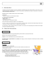
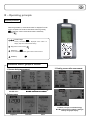
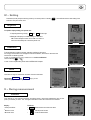
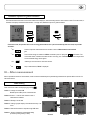
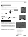
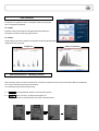
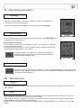
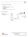
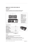
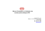
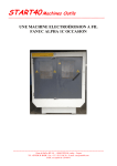
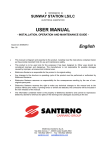
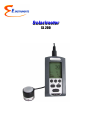
Solarimeter
SL 200
Table of contents
3
I – Introduction........................................................................................................................................4
II – General information.......................................................................................................................4
Measured units..........................................................................................................................................................................................4
Use...................................................................................................................................................................................................................4
III – Operating principle........................................................................................................................5
Keyboard presentation...........................................................................................................................................................................5
Three groups of display..........................................................................................................................................................................5
IV – Setting...............................................................................................................................................6
Brightness....................................................................................................................................................................................................6
Calibration....................................................................................................................................................................................................6
About..............................................................................................................................................................................................................6
V – During measurement....................................................................................................................6
Irradiance.....................................................................................................................................................................................................6
Radiant exposure or irradiation..........................................................................................................................................................7
VI – After measurement......................................................................................................................7
Data reading................................................................................................................................................................................................7
Stored data reading.................................................................................................................................................................................8
Data evaluation..........................................................................................................................................................................................9
New measurement – Resetting memory.......................................................................................................................................9
VII – Operating information................................................................................................................10
Over-range....................................................................................................................................................................................................10
Sensor default............................................................................................................................................................................................10
Power.............................................................................................................................................................................................................10
VIII – Maintenance.................................................................................................................................10
Servicing........................................................................................................................................................................................................10
Clock...............................................................................................................................................................................................................10
Regular checking.......................................................................................................................................................................................11
Batteries and adaptors replacement...............................................................................................................................................11
IX – Main specifications.......................................................................................................................11
SL200............................................................................................................................................................................................................11
Solar cell........................................................................................................................................................................................................12
Standard reference..................................................................................................................................................................................12
X – Metrology..........................................................................................................................................12
Traceability...................................................................................................................................................................................................12
Sensor replacement................................................................................................................................................................................12
XI – Delivery and packaging................................................................................................................13
XII – Accessories....................................................................................................................................13
4
I – Introduction
In addition to environmental applications, and face to development of renewable energy, SL 200 instrument allows to control on test or on site,
equipment with thermal or photovoltaic sensors. Thanks to its big capacity of measurement and storage, SL 200 becomes an instrument of
control and investigation particularly suited.
SL 200 instrument is a portable instrument which can measure and display :
Instantaneous:
● Irradiance or irradiation for spot check measures in W/m².
On a timed duration of measurement:
●
Max./min. values
● Average value of irradiance
●
Accumulated energy or radiant exposure in Wh/m²
Data are saved when the instrument is stopped or in case of battery failure.
Its sensor is composed of a strained silicon cell, not very sensitive to the thermal changes. It absorbs the solar radiation through a diffusor and a
correction filter. The output voltage of the sensor is related to the received radiation.
SL 200 instrument is mainly an efficient and easy-to-use instrument : with small size, it has a large display with a resolution of 64*128 pixels
involving a very high electronic technology.
II – General information
Measured units
SL 200 instrument can process the energy intensity emitted by the solar radiation in a precise place of the earth .
Expression of the solar energy and associated units :
Irradiance is the solar radiant flow received by unit area, expressed in W/m².
The radiant exposure or global irradiation is the quantity of solar energy by unit area: it's the product of irradiance by the duration of irradiation,
expressed in Wh/m²
Use
Solar radiation :
Among all solar radiations, (opposite draw),
SL 200 was designed to measure the sum of direct solar radiation and diffuse solar radiation, which
constitutes global solar radiation.
For any application, before, during and after the installation of solar thermal photovoltaic sensors, it is
required to control means of measurement to obtain valid and coherent results. Means of use of the
instrument has at least so much importance on the result than the quality of the instrument.
It is definitely necessary to take into account the influence of environment, in particular :
1. Position or direct correctly solar cell of SL 200 instrument, according to location of
solar sensors or supports (roof, terrace...)
2. Avoid dark areas (present or to come)
3. Go away as much as possible from reflecting zones
5
III – Operating principle
Keyboard presentation
When being switched on, “measurement screen” is displayed. From this
screen, the operator has access to three others screens by pressing
on keyboard; return to measurement screen is obtained by
activating
.
Function keys
Directly associated to text displayed shown above on
display, they allow measurement setting.
Key “leaves current screen”
Screen key
From measurement screens, give access to other screens
On/Off key
Instrument offers 3 groups of screens
2- Reading screens after measurement
1- Screens during measurement
Irradiance
Min./Max value
Irradiation, average, accumulated energy,
Min./Max instantaneous irradiation
3- Setting screens
Irradiation, average, accumulated energy,
Min./Max instantaneous irradiation, reading of
memory and graphic display
Brightness
Calibration
About
6
IV – Setting
Accessible from the principal measuring screen by successive pushes on the key
instrument. They also inform users.
, those different screens allow setting of the
Brightness
To optimize display reading, the operator can :
1. Adjust brightness by pressing
+
and
-
function keys.
2. Backlight LCD display for a better reading in a dark place.
“No” means backlight is switch off and “Yes” it is switch on.
In this last case, battery life is reduced by about 15%.
Brightness
Calibration
To recall calibration conditions including calibration coefficient of the sensor.
It is strongly recommended not to change the instrument calibration, this screen is reserved to the
manufacturer or laboratory partner.
In case of unwanted push on a key, an alert occurs: Caution modification! .
Leave via the keys
or
In case of sensor replacement, please refer to METROLOGY Chapter.
Calibration coefficient
About
Information on origin of manufacture and dates of last and next audits.
By pressing French and English
Choose language : French or English.
keys, you can
About - French
V – During measurement
About - English
Irradiance
Once switched on, the instrument measures and displays twice a second the instantaneous value of solar
power (or irradiance) in W/m2. This value gives information to users about sunshine local conditions.
Display :
Functions :
●
Solar power W/m2
●
Reset minimum and maximum values
●
Maximum value
●
Activate pause function
●
Minimum Value
●
Continue measurement
Energetic exposure
7
Radiation exposure or global irradiation
The instrument measures twice a second the irradiance and displays it, while memorizing minimum and maximum values. From these data , it
calculates and displays the measurement duration : average value, Radiation exposure or global irradiation.
From start screen, the operator have access to energy measurement over a period controlled by timer and clock, he proceeds
as follows:
●
1x
Access to exposure measurement and in sunshine control Irr. Measurement is not launched
yet.
●
1x
Launch of the energy accumulation in Wh/m² visualized by the “On” pictogram
which flashes . The
chronometer starts, it indicates secondes-minutes- hours-day (max : 03D00H00M00S). First average values
and accumulated energy values appear.
1x
Switching to second screen to recall max and min.
1x
Stop of measurement, ''Reset'' is displayed.
●
●
VI – After measurement
After a requested shut-down of measurement, results are saved automatically and systematically presented to the operator before a launch of a
new measurement.
Data reading
Three successive screens are displaying by pressing
Screen 1 : Average of Irradiance M
Radiant exposure E on period of measurement
Screen 2 :Screen 1 + minimum and maximum value of
instantaneous irradiation
Screen 1
Screen 2
Screen 3
Screen 4
Screen 5
Screen 6
Screen 3 : Reading of saved data
Screen 4 : Viewing of graphic display of stored data each day of 24
hours.
Screen 5 : Data transfer toward a computer trough USB cable
Screen 6 : Screen of brightness and backlight setting
(if necessary during reading of data)
8
Data stored reading
Screen 3 :
●
Irr : represents the averaged value over a minute with date and time indicated of irradiance.
E : represents the energetic exposure in Wh/m2 accumulated from the beginning of measurement until date
and time displayed.
To facilitate evaluation data, user can choose the scanning pitch through the D ,
H , M
key :
D for date
H for hour
M for minute
then through arrow keys
and time.
●
<
(decremented) and
>
Stored data
(incremented) user displays the searched date
Screen 4 :
This screen visualizes a daily graphic display of irradiance values from 0:00 am to 0:00 pm on a scale of
1300 W/m² maximum
Choice of the day is made through arrow keys < (decrements) and > (increments).
The Val pictogram appears. Press Val key to change the graph and to visualize it.
Graphic
Data transfer
Screen 5 ''Data transfer '' allows data transfer toward a computer trough USB cable.
DL 200 software have been previously loaded into the computer (see notice of
DL 200 Software ).
To access screen 5 from reading screen, press
to obtaining the screen data
transfer. Then press USB symbol.
Once the connection, computer detects SL200 instrument on the appropriate port.
The software allows only the transfer, the instrument is still pending.
It only indicates date and time (which can be updated through software DL200).
Data transfer
File Format :
File values adopt a text termination : txt, which is easily exploitable by a Excel
spreadsheet for example.
Data transfer
--------------------------------------------------------------SL N°9999
Raw data from the collector
--------------------------------------------------------------Contents the 08/07/2008 at 18:31:52
--------------------------------------------------------------08/06/2008,11:10:00,beginning
13/06/2008,13:09:00,end
08/06/2008,11:10:00,0007
08/06/2008,11:11:00,0019
08/06/2008,11:12:00,0021
08/06/2008,11:13:00,0023
08/06/2008,11:14:00,0025
08/06/2008,11:15:00,0025
Data file text format
9
Data evaluation
Customized treatment of .txt file
The operator can organize his control or investigation folder by importing .txt
file in an appropriate spreadsheet.
For example
Evaluation of the .txt file through DL 200 software allows rapid obtaining of
tracing time of irradiance and an easy graphic process.
For example :
These images can be saved or printed for an integration into the corresponding folder.
Images are saved in .jpg format.
Complete file
Zoom on a specific day
New measurement – Resetting memory
After recording of results in its folder or transfer toward a computer, the operator can launch a new measurement. Before, he imperatively
has to erase stored data of the previous measurement.
From the reading screen, please proceed this way :
1. 1 x
A message alerts the operator of a reset of memory backup.
2. 1 x
Memory is erasing , visualized by the progress bar.
Memory is erased, the operator can launch a new measurement.
10
VII – Operating information
Over-range
Although it is quite impossible , in very special conditions of reflections concentrated to the
sensor, a pictogram of exceeded range appears
.
It comes for an irradiance higher to 1300 W/m2. The maximum value will indicate 1301 W/m².
Sensor default
Overrange
In case of a defective sensor (sensor unplugged) during the measurement, symbols
and disappear after its proper connection.
***
appear
During the dysfunction sequence :
The chronometer still running correctly, it indicates to the operator the real duration of measurement
containing the time of sensor default.
Max. min., M. irradiation values are false. Only the energetic exposure is exploitable on the duration of
running without sensor default detected by the instrument.
To remind the operator this default and to keep it into consideration in
exploitation of results, a pictogram is at the top of the screen for the measure. It
is also displayed after the measurement.
Sensor default
Power source
When the instrument is equipped with alkaline batteries, it can operate for 72 hours minimum. A symbol informs the user
about electric power remaining. If battery is low, less than 1 bar on the pictogram, the instrument stops measuring, save
current measurement and switches off.
VIII – Maintenance
Servicing
The SL 200 instrument conception allows a reduce maintenance which consists in changing batteries and cleaning the sensor with a cloth
slightly dampened.
Clock
SL200 instrument has a permanent clock powered by an internal battery that is recharged when the device is switched on. In case of nonuse of the device, the battery will allow the running of the clock for 6 months.
After 6 months or at the start of the device, if it is displayed a wrong time (eg: 00:00), it means that it is necessary to recharge battery.
Switching SL200 instrument for about two hours allows its recharge.
Important : The correct resetting of the clock is made through a computer and the DL 200 software (cf. instructions for use of DL 200
software).
11
Regular checking
Like most measuring instruments, it is strongly recommended to regularly control and calibrate SL200. Return to the manufacturer each year
will provide necessary metrological traceability.
Batteries replacement – adaptors
Batteries :
To replace batteries, open the back hatch and insert the 3 new batteries of type 1.5 V / AAA-LR3 inside.
Warning: respect meaning of batteries. If storage is very long, remove batteries.
Adaptors :
Depending on the conditions of measurement, there are several possibilities of power supply of SL200 :
- Connecting to the USB plug of a computer
- USB adapter type
- Medium capacity battery pack
- High-capacity battery pack
(Cf : accessories)
Note: when using with an external power, it is recommended to remove batteries from SL100. An internal protection, however, allows to secure all if
you forget it.
IX – Main specifications
SL200
Solar irrigation measuring range..........from 1 W/m2 to 1300 W/m2
Energetic exposure measuring range...from 1 Wh/m2 to 500 kWh/m2
Frequency of the measure.....................2 / s
Accuracy.................................................5% of measurement
Calculation frequency (W/m2)................1 / min (average on 60 seconds)
Storage capacity....................................31 days, 44640 saved recording points
Fast datas download..............................1000 values/second
Detection................................................out of range and sensor default
Operating temperature..........................from -10°C to +50°C
Storage temperature..............................from -10°C to +55°C
Package dimensions..............................58 x 120 x 33 mm
Autonomy...............................................more than 72 hours in continuous mode
Unlimited with power supply adapter
Power supply.........................................3 LR3-AAA batteries
Electronic...............................................Digital
Electronic card.......................................Varnish
Conformity..............................................in accordance with RoHS directives
12
Solar cell
Spectral response ..................................................................from 400 to 1100 nm
Nominal calibration coefficient..............................................100mv for 1000W/m2
Response in cosine.................................................................corrected until 80°
Coefficient in temperature......................................................+0.1%/°C
Operating temperature............................................................from -30°C to +60°C
Humidity dependence.............................................................100% HR
UV performance.......................................................................excellent (PMMA filter)
Mode.........................................................................................photovoltaic
Surface active..........................................................................1 cm2
Material.....................................................................................Polycristallin silicon
Front face.................................................................................Translucent PMMA
Tightness.................................................................................Polyurethance resine and housing
PMMA and polyacetol
Cell weight...............................................................................60 g
Cell dimensions.......................................................................30 x 32 mm
Standard reference
This instrument is based on recommendations and requirements of the standard ISO9060 -1990: Solar energy - Specification and
classification of instruments for measuring solar radiation hemispheric and direct.
X – Metrology
Traceability
Calibration of this instrument was performed to determine calibration coefficient of the sensor with a method by comparison with a working
standard radiometer attached to the World Reference radiometric (DPR).
A calibration certificate is provided with the instrument..
Sensor replacement
In case of accidental damage of the sensor and impossibility of return the instrument for
troubleshooting, user can ask for a new sensor to our after sales service .
This one is provided with a calibration certificate showing its coefficient expressed in μV/W/m2.
To change this coefficient and adapt this new sensor to the SL 200, you have to enter its value by
pressing + or - . A last imperative press on the key Val finalize the recording of the
new sensor calibration certificate.
Remember : to avoid unwanted manipulation and from the first press on a function key, an alert appears:
Caution!Modification. Exit the calibration function if necessary trough the key
or
.
Calibration certificate
13
XI – Delivery and packaging
SL 200 housing
Silicium sensor and 1.25 metre of cable with mini -DIN connector
● Transport case with foam protection
● 3 LR3-AAA batteries
● Instructions for use
● Calibration certificate
●
CD with Instruction for use of SL 200 instrument and DL 200 software
●
●
XII – Accessories
Tripod
Fixing kit for solar panels
● Extensions : 5m, 10m and on demand
● Power supply adaptor
●
●
E Instruments International LLC
172 Middletown Blvd - Suite B201
Langhorne, PA 19047
Tel.: 215 750 1212
Fax: 215 750 1399
E-mail: [email protected]
Web: www.E-Inst.com
Distributed by: