1
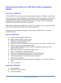
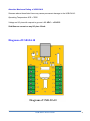
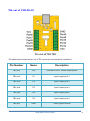
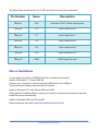
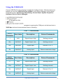
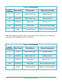
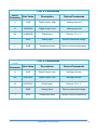
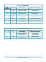
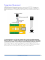
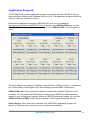
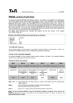
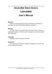
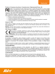
Model : USB-DA10 Web: www.titan.tw Support: [email protected] Manual Part Number TN-071 Issue Date: 2012-06-20 Content Introduction & Features of USB 10-Port Data Acquisition Module .......... 2 Introduction of USB-DA10 ............................................................................................ 2 Features of USB-DA10 ................................................................................................. 2 Application of USB-DA10.............................................................................................. 2 Absolute Maximum Rating of USB-DA10 ..................................................................... 3 Diagram of USB-DA10 ................................................................................. 3 Pin-out of USB-DA10 ................................................................................... 4 Driver Installation ........................................................................................ 5 Using the USB-DA10 ................................................................................... 6 Temperature Measurement ........................................................................11 Application Program ..................................................................................12 USB-DA10 User Guide 1 Introduction & Features of USB 10-Port Data Acquisition Module Introduction of USB-DA10 TITAN USB-DA10 is a low-cost 10-port data acquisition module for USB port, which allows for an easy way to link from USB ports on computers for measuring voltage, controlling and monitoring process, and acquiring temperature data. Each of 10 available ports can be configured for any of digital or analog modes; the port 6 ~10 also can be configured for temperature measuring via single-byte commands. USB-DA10 is powered by the USB port of host PC (5V, 500mA), and it can provide output power (5VDC, 200mA) for external circuit power requirement. Windows and Linux application programs are provided with USB-DA10 to control all available functions. Features of USB-DA10 Provides 10 ports digital input/output. Digital output: Set high, or clear to low. Digital input: Read the high/ low state. Provides 10 ports analog input. Read and return the voltage on each I/O pin using a 10-bit A/D: 0 ~ 5 VDC range. Provides 5 ports temperature measure input. Using a digital temperature sensor, measure temperature range from -55°C ~ 125°C (-67°F to 257°F). USB port powered, no external power supply need. USB 1.1 and USB2.0 compatible interface. Easy to use with single-byte commands to control all function. Can utilize a simple terminal emulator to control all function. Provides terminal block connector for easy connection. LED for power indication. Drivers and application program provides for Windows 8, 7, Vista, XP, 2000 and Linux. CE, FCC approval. Application of USB-DA10 Data Acquisition Industrial / Process Control Process Monitoring USB-DA10 User Guide 2 Absolute Maximum Rating of USB-DA10 Stresses above those listed here may cause permanent damage to the USB-DA10: Operating Temperature: 0°C ~ 70°C Voltage on I/O pins with respect to ground: -0.3 VDC ~ +5.3VDC Sink/Source current on any I/O pins: 25mA Diagram of USB-DA10 USB-DA10 User Guide 3 Pin-out of USB-DA10 The table below shows the pin-out of TB1 (seven-pin terminal block connector). Pin Number Name Description TB1 pin1 VCC Provides +5VDC 100mA output power TB1 pin2 P1 Input/ output port 1 TB1 pin3 P2 Input/ output port 2 TB1 pin4 P3 Input/ output port 3 TB1 pin5 P4 Input/ output port 4 TB1 pin6 P5 Input/ output port 5 TB1 pin7 GND GND: Signal Ground USB-DA10 User Guide 4 The table below shows the pin-out of TB2 (seven-pin terminal block connector). Pin Number Name Description TB2 pin1 VCC Provides +5VDC 100mA output power TB2 pin2 P6 Input/ output port 6 TB2 pin3 P7 Input/ output port 7 TB2 pin4 P8 Input/ output port 8 TB2 pin5 P9 Input/ output port 9 TB2 pin6 P10 Input/ output port 10 TB2 pin7 GND GND: Signal Ground Driver Installation In most cases, the driver of USB-DA10 will be installed automatically. Install in Windows 8, 7, Server 2008 R2 Connect your computer to Internet and plug USB-DA10 to the USB port. The driver will be installed automatically via Internet. Install in Windows XP, Vista, Server 2003 and 2008 When asked to install the drivers, allow your computer to search the Internet to load and install the drivers automatically. Install in Windows 2000, 98, SE and ME Download drivers from http://www.titan.tw/download/driver.html USB-DA10 User Guide 5 Using the USB-DA10 Connect USB-DA10 to the computer to initiate the loading of driver. After the drivers are loaded, you can find “USB Serial Port (COMx)” under Device Manager of the System Properties screen. (Go there by Start-Setting- Control Panel- System Properties Hardware- Device- Device Manager). You can use a terminal emulator program to opening this COM port, set the baud rate to 38400 bps and send commands as shown in following : Port 1 Commands ASCII Character Hex Value Description Return/Commands 1 0x31 Digital Output :High Nothing returned Q/q 0x51/0x71 Digital Output :Low Nothing returned A/a 0x41/0x61 Digital Input Returns “H” or “L” Z/z 0x5A/0x7A Analog Input Returns measured voltage Port 2 Commands ASCII Character Hex Value Description Return/Commands 2 0x32 Digital Output :High Nothing returned W/w 0x57/0x77 Digital Output :Low Nothing returned S/s 0x53/0x73 Digital Input Returns “H” or “L” X/x 0x58/0x78 Analog Input Returns measured voltage USB-DA10 User Guide 6 Port 3 Commands ASCII Character Hex Value Description Return/Commands 3 0x33 Digital Output :High Nothing returned E/e 0x45/0x65 Digital Output :Low Nothing returned D/d 0x44/0x64 Digital Input Returns “H” or “L” C/c 0x43/0x63 Analog input Returns measured voltage Port 4 Commands ASCII Character Hex Value Description Return/Commands 4 0x34 Digital Output :High Nothing returned R/r 0x52/0x72 Digital Output :Low Nothing returned F/f 0x46/0x66 Digital Input Returns “H” or “L” V/v 0x56/0x76 Analog input Returns measured voltage Port 5 Commands ASCII Character Hex Value Description Return/Commands 5 0x35 Digital Output :High Nothing returned T/t 0x54/0x74 Digital Output :Low Nothing returned G/g 0x47/0x67 Digital Input Returns “H” or “L” B/b 0x42/0x62 Analog input Returns measured voltage USB-DA10 User Guide 7 Port 6 Commands ASCII Character Hex Value Description Return/Commands 6 0x36 Digital Output :High Nothing returned Y/y 0x59/0x79 Digital Output :Low Nothing returned H/h 0x48/0x68 Digital Input Returns “H” or “L” N/n 0x4E/0x6E Analog Input Returns measured voltage - 0x2D Temperature Input Returns current temperature Note: If the digital temperature sensor is not connected to the USB-DA10 for measuring temperature, the message box will show “999.99°”. Port 7 Commands ASCII Character Hex Value Description Return/Commands 7 0x37 Digital Output :High Nothing returned U/u 0x55/0x75 Digital Output :Low Nothing returned J/j 0x4A/0x6A Digital Input Returns “H” or “L” M/m 0x4D/0x6D Analog Input Returns measured voltage = 0x3D Temperature Input Returns current temperature USB-DA10 User Guide 8 Port 8 Commands ASCII Character Hex Value Description Return/Commands 8 0x38 Digital Output :High Nothing returned I/i 0x49/0x69 Digital Output :Low Nothing returned K/k 0x4B/0x6B Digital Input Returns “H” or “L” , 0x2C Analog Input Returns measured voltage [ 0x5B Temperature Input Returns current temperature Port 9 Commands ASCII Character Hex Value Description Return/Commands 9 0x39 Digital Output :High Nothing returned O/o 0x4F/0x6F Digital Output :Low Nothing returned L/l 0x4C/0x6C Digital Input Returns “H” or “L” . 0x2E Analog Input Returns measured voltage ] 0x5D Temperature Input Returns current temperature USB-DA10 User Guide 9 Port 10 Commands ASCII Character Hex Value Description Return/Commands 0 0x30 Digital Output :High Nothing returned P/o 0x50/0x70 Digital Output :Low Nothing returned ; 0x3B Digital Input Returns “H” or “L” / 0x2F Analog Input Returns measured voltage ` 0x60 Temperature Input Returns current temperature Setup Commands ASCII Character Hex Value Description Return/Commands ! 0x21 Set the Centigrade(°C) is temperature unit Default setting; nothing returned @ 0x40 Set the Fahrenheit(°F) is temperature unit Nothing returned USB-DA10 User Guide 10 Temperature Measurement USB-DA10 provides 5 channels temperature measure input (P6~P10). You can use a MAXIM BS18B20 or DB18B20+ digital temperature sensor to connect to USB-DIO for measuring temperature. Following shows an example of the connection using I/O port 6 (P6). For best performance, use Cat5 type computer cable to connect the digital temperature sensor to USB-DA10. Two pairs of wires in the Cat 5 cable are required for the connection. The first pair is for power (VDD) and ground, and the second pair is data (DQ) and ground. In this temperature measure circuit, a pull-up resistor is required for the data line of approximately 1.5K ohms. If the length of Cat 5 is greater than 100 feet, it may require a pull-up resistor value of less than 1.5K ohms in order to achieve usable rise times at the sensor. The minimum safe resistance for the pull-up resistor is 240 ohms. USB-DA10 User Guide 11 Application Program TITAN USB-DA10 provides application program to interface with the USB-DA10 10-port data acquisition module under Windows and Linux O.S. This application program allows the users to control all available functions. Download the application program (USB-DA10-AP.exe) from our webpage: http://www.titan.tw/download/USB-DA10.html. Double click “USB-DA10-AP.exe” to start the USB-DA10 Windows application program, or click “USB-DA10-AP” for the program in Linux. The main dialog box consists of COM port, Search Device, COM port status, Temperature unit, Digital Output, Read Digital Input, Read Analog input and Read Temperature. COMx (COM port): When this field is checked, it shows the available COM port of your computer. You can select the COM port for connecting the USB-DA10 data acquisition module to your computer by manual. (After the USB-DIO drivers are loaded, you can find “USB Serial Port (COMx)” under Device Manager of the System Properties screen). Search Device: When this field is checked, your USB-DA10 application program will acquire a COM port and connected to your computer automatically. USB-DA10 User Guide 12 COM port status: This field showed the status of COM port when the USB-DA10 connected to your computer, it will show “Open Success!! Find USB-DA10”. Centigrade/°C: When this field is checked, set the Centigrade (°C) as temperature unit. Fahrenheit/°F: When this field is checked, set the Fahrenheit (°F) as temperature unit. Digital Output: This is an output digital signal function. When “High” field is checked, the selected port of USB-DA10 outputs a high level signal. When “Low” field is checked, the selected port of USB-DA10 outputs a low level signal. Read Digital Input: This is a read digital signal function. After the “Read Digital Input” field is checked, the message box shows “H”, when the selected port of USB-DA10 detects a high level digital signal. The message box shows “L”, when the selected port of USB-DA10 detected a low level digital signal. Read Analog Input: This is an analog signal measuring function. When the “Read Analog Input” field is checked, the message box shows the input voltage for the selected port of USB-DA10. Read Temperature: This is a temperature measuring function. When the “Read Temperature” field is checked, the message box shows the measured temperature for the selected port of USB-DA10. If the digital temperature sensor is not connected to the USB-DA10 for measuring temperature, the message box will show “999.99°”. Copyright © 2012 TITAN Electronics Inc. All brand names and trademarks are the property of their respective owners. USB-DA10 User Guide 13 Trademarks TITAN and the logo is a registered trademark of TITAN Electronics Inc. in Taiwan. Microsoft, Windows, Windows XP, Windows Vista, Windows Server, Windows 7, Windows 8 are trademarks of Microsoft Corporation. All other trademarks and brands are property of their respective owners. Copyright Copyright 2012-2014 TITAN Electronics Inc. All rights are reserved. Reproduction of the manual and software without permission is prohibited. Disclaimer TITAN Electronics Inc. provides this document and computer programs “as is” without warranty of any kind, expressed or implied, including, but not limited to, its particular purpose. TITAN Electronics Inc. reserves the right to make improvements and changes to this user manual, or to the products, or the computer programs described in this manual, at any time. Information provided in this manual is intended to be accurate and reliable. However, TITAN Electronics Inc. assumes no responsibility for its use, or for any infringements on the rights of third parties that may result from its use. This product might include unintentional technical or typographical errors. Changes are periodically made to the information herein to correct such errors, and these changes are incorporated into new editions of the publication. USB-DA10 User Guide 14