1
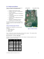
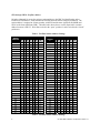
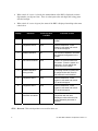
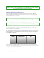
CTI 2500-RBC
PROFIBUS REMOTE BASE CONTROLLER
INSTALLATION AND OPERATION GUIDE
Version 1.2
CTI Part # 062-00364-012
*062-00364-012*
2500RBCIOG 080309
Copyright ©2005 Control Technology Inc.
All rights reserved.
This manual is published by Control Technology Inc., 5734 Middlebrook Pike, Knoxville, TN 37921.
This manual contains references to brand and product names which are tradenames, trademarks,
and/or registered trademarks of Control Technology Inc. Siemens® and Simatic® are registered
trademarks of Siemens AG. Other references to brand and product names are tradenames,
trademarks, and/or registered trademarks of their respective holders.
DOCUMENT DISCLAIMER STATEMENT
Every effort has been made to ensure the accuracy of this document; however, errors do occasionally
occur. CTI provides this document on an “as is” basis and assumes no responsibility for direct or
consequential damages resulting from the use of this document. This document is provided without
express or implied warranty of any kind, including but not limited to the warranties of
merchantability or fitness for a particular purpose. This document and the products it references are
subject to change without notice. If you have a comment or discover an error, please call us toll-free
at 1-800-537-8398 or email us at [email protected].
REVISION HISTORY
V1.0
V1.1
V1.2
V1.21
04/30/04
08/25/04
05/03/07
06/22/09
08/03/09
Original Issue
Changed Profibus address switch open/close labeling
Fixed Profibus connector diagram, added 2500 Series processors
Added reference to WorkShop Profibus configuration documentation
Corrected Profibus cable impedance typo on p.30 from “135” to “35”
PREFACE
This Installation and Operation Guide provides reference information for the CTI 2500-RBC
Profibus Remote Base Controller. The information in this manual is directed to individuals who will
be installing the module and configuring it for use with a Profibus Master.
We assume you are familiar with the installation and operation of:
1)
CTI 2500 Series and Simatic® 505® programmable controllers,
2)
PLC WorkShop™ for Siemens 505™ or Com Profibus Configuration Software
Please refer to the appropriate user documentation for specific information on your programmable
controllers and I/O modules.
CTI 2500-RBC Installation and Operation Guide V1.2
i
USAGE CONVENTIONS
NOTE:
Notes alert the user to special features or procedures.
CAUTION:
Cautions alert the user to procedures that could damage equipment.
WARNING:
Warnings alert the user to procedures that could damage equipment and endanger the user.
TABLE OF CONTENTS
CHAPTER 1. DESCRIPTION .................................................................................... 1 1.1. Introduction ...........................................................................................................1 CHAPTER 2. INSTALLATION .................................................................................. 3 2.1. Installation Planning..............................................................................................3 Choosing Profibus Media
Wiring the Profibus Connector
Selecting a Profibus Address
Selecting a Profibus Speed
Selecting Slave Parameters
Setting Module Hardware Options
3 3 3 4 4 4 2.2. Power Requirements ............................................................................................4 2.3. Unpacking the Module ..........................................................................................4 2.4. Configuring the Module ........................................................................................5 Setting the Module Option Switches
Setting the Output State on Communications Loss
Setting Software Parameters in WorkShop or Com Profibus
Configuring the Remote Base in WorkShop or Com Profibus
Exporting a Binary Configuration File from Com Profibus
Merging the Configuration File into the Profibus Master
5 9 10 10 10 10 2.5. Physical Installation ........................................................................................... 10 2.6. Connecting the Profibus Cable ......................................................................... 11 2.7. Diagnostics ........................................................................................................ 12 2.8. Base Mismatch Handling in the 2500-RBC ...................................................... 12 2.9. Differences Between the 2500-RBC and the 505-6870 ................................... 13 2.10. Diagnostics ...................................................................................................... 13 PLC Status Words
Diagnostic Bytes from the 2500-RBC
13 14 CHAPTER 3. SETTING UP THE 2500-RBC USING WORKSHOP OR COM
PROFIBUS ................................................................................................... 17 3.1. Overview ............................................................................................................ 17 3.2. Startup Com Profibus ........................................................................................ 17 3.3. Import the 2500R.gsd file into Com Profibus .................................................... 18 3.4. Set Bus Parameters........................................................................................... 19 3.5. Add a Master to the System and Set the Profibus Address. ............................ 20 3.6. Add the 2500-RBC to the System ..................................................................... 23 3.7. Configure the 2500-RBC ................................................................................... 23 3.8. Save the Profibus Configuration and Export the Binary File ............................ 25 3.9. Merge the Binary File in Workshop ................................................................... 26 3.10. Write the Configuration to the Base(s) ............................................................ 28 3.11. Select Synchronous or Asynchronous and Start Profibus ............................. 28 APPENDIX A. PROFIBUS INSTALLATION GUIDELINES .................................. 30 General Installation Information................................................................................ 30 Maximum number of stations
Cable Type
Cable Lengths
CTI 2500-RBC Installation and Operation Guide V1.2
30 30 30 i
Bus termination
Bus connectors and PROFIBUS-DP/FMS interface
31 31 Cable laying guidelines..............................................................................................33 Laying of copper cable
Laying cables within control cabinets
Laying cables outside of control cabinets
SPECIFICATIONS ...................................................................................................36 General ......................................................................................................................36 Ports ...........................................................................................................................36 Environmental ............................................................................................................36 LIMITED PRODUCT WARRANTY ..........................................................................38 REPAIR POLICY......................................................................................................39 33 34 35 CHAPTER 1. DESCRIPTION
1.1. Introduction
The CTI 2500-RBC Profibus Remote Base Controller is
a member of Control Technology's family of I/O
modules compatible with the programmable controllers.
The 2500-RBC Profibus Remote Base Controller (RBC)
allows a CTI 2500 Series or Simatic® 505 I/O base to
function as a slave node on a Profibus-DP I/O channel
that complies with the PROFIBUS standard (DIN
19245, Part 3). The 2500-RBC is intended to be a
replacement for the Siemens® 505-6870 RBC. It
provides the following functions:
x
x
x
x
x
Compatible with CTI 2500 Series, Simatic®
505, Siemens® S5 and S7 masters
Can be used in currently-available CTI and
Siemens® 4-, 8-, and 16-slot bases
Supports communication speeds from 9.6 Kbaud
(maximum cable distance per segment: 1200 m)
up to 12 Mbaud (maximum cable distance per
segment: 100 m).
Includes an LED display which shows error
codes or current station address.
Configurability using the Siemens® 505-6870
“gsd” file or the new CTI 2500-RBC “gsd” file
which can be downloaded from our web site
The 2500-RBC resides in CTI 2500 Series or Simatic®
505 base. It installs in the second slot from the left,
adjacent to the power supply module.
Figure 1. 2500-RBC Front Panel
CTI 2500-RBC Installation and Operation Guide V1.2
1
CHAPTER 2. INSTALLATION
The installation of the Model 2500-RBC Profibus Remote Base Controller consists of the following
steps:
1)
2)
3)
4)
5)
6)
Planning the installation,
Verifying power requirements
Unpacking and configuring the module,
Physical installation,
Connecting cables,
Checking the module operation.
2.1. Installation Planning
Choosing Profibus Media
The 2500-RBC attaches directly to the Profibus-DP RS485 cable using a DB9 connector. The
Profibus organization recommends using bus cable as specified in EN 50170 part 8-2 and “Cable
Type A”, and should comply with the parameters below. An example cable of this type would be
Belden 3079A.
For more information on Profibus installation guidelines, see Appendix A.
Wiring the Profibus Connector
The Profibus connector should be wired as shown in Section 2.6. For more information, refer to
Appendix A.
Selecting a Profibus Address
Before proceeding, you must determine what Profibus address you will assign to the module.
Profibus addresses range from 0 to 127. In CTI 2500 Series and Simatic® 505 systems, address 0
and addresses 113-127 are not valid. Therefore, any address between 1 and 112 is valid for the RBC
when installed in these systems. Note that each slave node and the master must have a unique address
on the bus.
CTI 2500-RBC Installation and Operation Guide V1.2
3
Selecting a Profibus Speed
Before proceeding, you must determine your Profibus operating speed. The 2500-RBC supports
Profibus speed from 9.6K bits/s to 12M bits/s. For more information on selecting Profibus speed see
Appendix A.
Selecting Slave Parameters
The 2500-RBC supports four parameterization options. These options are set using WorkShop, or
using the “properties” screen for the remote base in Com Profibus. For more information about these
settings, see “Setting Software Parameters in Com Profibus” in Section 2.4.
Setting Module Hardware Options
In addition to the Profibus address, the module includes a hardware setting for selecting the state of
the base discrete outputs in the event of a communications loss. The module can be configured to set
all outputs off, or to leave outputs at their last values.
2.2. Power Requirements
The CTI 2500-RBC module consumes 2.5 watts of +5 VDC power from the backplane. Before
installing the RBC, verify that your mounting base power budget can accommodate the required
power. A good tool for performing the verification is the CTI Replacement Guide and Power
Calculator, available from our website at
ftp://ftp.controltechnology.com/public/Download/tools/
2.3. Unpacking the Module
Open the shipping carton and remove the special anti-static bag that contains the module.
After discharging any static build-up, remove the module from the static bag. Do not discard the
static bag. Always use this bag for protection against static damage when the module is not inserted
into the I/O base.
CAUTION:
The components on the 2500-RBC module printed circuit card can be damaged by static
electricity discharge. To prevent this damage, the module is shipped in a special anti-static
bag. Static control precautions should be followed when removing the module from the bag
and when handling the printed circuit card during configuration.
4
CTI 2500-RBC Installation and Operation Guide V1.2
2.4. Configuring the Module
There are six steps to configuring the module and
getting it operational on a Profibus network:
option switches
freeze jumper setting
1. Setting the module option switches
2. Setting the output state on communication
loss (freeze jumper)
3. Setting software parameters in WorkShop or
Com Profibus
4. Configuring the remote base in in WorkShop
or Com Profibus
5. Exporting a binary configuration file (Com
Profibus only)
6. Merging the configuration file into the
Profibus master (Com Profibus only)
For detailed information on using Com Profibus to
configure a remote base with the 2500-RBC, refer to
Chapter 3.
Setting the Module Option Switches
Switches on the 2500-RBC are used to select the
following
• Serial Port Baud Rate
• Profibus Address
• Display mode
Figure 2. Switch Locations
Figure 2 indicates the location of the option switches and freeze jumper. The remainder of this
section describes the function of the individual switches.
SW1 through SW3 – Serial Port Baud Rate.
Switches 1-3 are used for setting the baud rate of the serial port. Serial port operations are not
currently implemented in the product.
Baud rate
SW1
SW2
SW3
38400
0
0
1
19200
1
1
1
9600
1
1
0
2400
1
0
0
1200
0
1
0
300
0
0
0
Invalid
0
1
1
Invalid
1
0
1
CTI 2500-RBC Installation and Operation Guide V1.2
5
SW4 through SW10 - Profibus Address
Switches 4 through 10 are used to assign a station address to the RBC for identification on the
Profibus-DP I/O channel. Each station in the Profibus network must be uniquely numbered. The
station address is assigned as a binary number, with SW4 and the most significant bit (MSB) and
SW10 as the least significant (LSB). The table below shows how to set the dipswitch to a station
address between 0 and 125. Note that a switch in the “open” position=1 and a switch in the “closed”
position=0.
Table 1. Profibus Station Address Settings
Station
Address
0*
1
2
3
4
5
6
7
8
9
10
11
12
13
14
15
16
17
18
19
20
21
22
23
24
25
26
27
28
29
30
31
Switch Number / State
4
0
0
0
0
0
0
0
0
0
0
0
0
0
0
0
0
0
0
0
0
0
0
0
0
0
0
0
0
0
0
0
0
5
0
0
0
0
0
0
0
0
0
0
0
0
0
0
0
0
0
0
0
0
0
0
0
0
0
0
0
0
0
0
0
0
6
0
0
0
0
0
0
0
0
0
0
0
0
0
0
0
0
1
1
1
1
1
1
1
1
1
1
1
1
1
1
1
1
7
0
0
0
0
0
0
0
0
1
1
1
1
1
1
1
1
0
0
0
0
0
0
0
0
1
1
1
1
1
1
1
1
8
0
0
0
0
1
1
1
1
0
0
0
0
1
1
1
1
0
0
0
0
1
1
1
1
0
0
0
0
1
1
1
1
9
0
0
1
1
0
0
1
1
0
0
1
1
0
0
1
1
0
0
1
1
0
0
1
1
0
0
1
1
0
0
1
1
10
0
1
0
1
0
1
0
1
0
1
0
1
0
1
0
1
0
1
0
1
0
1
0
1
0
1
0
1
0
1
0
1
Station
Addres
s
32
33
34
35
36
37
38
39
40
41
42
43
44
45
46
47
48
49
50
51
52
53
54
55
56
57
58
59
60
61
62
63
Switch Number / State
4
0
0
0
0
0
0
0
0
0
0
0
0
0
0
0
0
0
0
0
0
0
0
0
0
0
0
0
0
0
0
0
0
5
1
1
1
1
1
1
1
1
1
1
1
1
1
1
1
1
1
1
1
1
1
1
1
1
1
1
1
1
1
1
1
1
6
0
0
0
0
0
0
0
0
0
0
0
0
0
0
0
0
1
1
1
1
1
1
1
1
1
1
1
1
1
1
1
1
7
0
0
0
0
0
0
0
0
1
1
1
1
1
1
1
1
0
0
0
0
0
0
0
0
1
1
1
1
1
1
1
1
8
0
0
0
0
1
1
1
1
0
0
0
0
1
1
1
1
0
0
0
0
1
1
1
1
0
0
0
0
1
1
1
1
9
0
0
1
1
0
0
1
1
0
0
1
1
0
0
1
1
0
0
1
1
0
0
1
1
0
0
1
1
0
0
1
1
10
0
1
0
1
0
1
0
1
0
1
0
1
0
1
0
1
0
1
0
1
0
1
0
1
0
1
0
1
0
1
0
1
Table 1. Profibus Station Address Settings
6
CTI 2500-RBC Installation and Operation Guide V1.2
Station
Address
64
65
66
67
68
69
70
71
72
73
74
75
76
77
78
79
80
81
82
83
84
85
86
87
88
89
90
91
92
93
94
Switch Number / State
4
1
1
1
1
1
1
1
1
1
1
1
1
1
1
1
1
1
1
1
1
1
1
1
1
1
1
1
1
1
1
1
5
0
0
0
0
0
0
0
0
0
0
0
0
0
0
0
0
0
0
0
0
0
0
0
0
0
0
0
0
0
0
0
6
0
0
0
0
0
0
0
0
0
0
0
0
0
0
0
0
1
1
1
1
1
1
1
1
1
1
1
1
1
1
1
7
0
0
0
0
0
0
0
0
1
1
1
1
1
1
1
1
0
0
0
0
0
0
0
0
1
1
1
1
1
1
1
8
0
0
0
0
1
1
1
1
0
0
0
0
1
1
1
1
0
0
0
0
1
1
1
1
0
0
0
0
1
1
1
9
0
0
1
1
0
0
1
1
0
0
1
1
0
0
1
1
0
0
1
1
0
0
1
1
0
0
1
1
0
0
1
10
0
1
0
1
0
1
0
1
0
1
0
1
0
1
0
1
0
1
0
1
0
1
0
1
0
1
0
1
0
1
0
Station
Addres
s
95
96
97
98
99
100
101
102
103
104
105
106
107
108
109
110
111
112
113*
114*
115*
116*
117*
118*
119*
120*
121*
122*
123*
124*
125*
Switch Number / State
4
1
1
1
1
1
1
1
1
1
1
1
1
1
1
1
1
1
1
1
1
1
1
1
1
1
1
1
1
1
1
1
5
0
1
1
1
1
1
1
1
1
1
1
1
1
1
1
1
1
1
1
1
1
1
1
1
1
1
1
1
1
1
1
6
1
0
0
0
0
0
0
0
0
0
0
0
0
0
0
0
0
1
1
1
1
1
1
1
1
1
1
1
1
1
1
7
1
0
0
0
0
0
0
0
0
1
1
1
1
1
1
1
1
0
0
0
0
0
0
0
0
1
1
1
1
1
1
8
1
0
0
0
0
1
1
1
1
0
0
0
0
1
1
1
1
0
0
0
0
1
1
1
1
0
0
0
0
1
1
9
1
0
0
1
1
0
0
1
1
0
0
1
1
0
0
1
1
0
0
1
1
0
0
1
1
0
0
1
1
0
0
10
1
0
1
0
1
0
1
0
1
0
1
0
1
0
1
0
1
0
1
0
1
0
1
0
1
0
1
0
1
0
1
NOTE:
The address setting on the 2500-RBC switches must match the address set for the base in
WorkShop or Com Profibus for proper operation
NOTE:
When connecting the 2500-RBC to a 545/555/575 CPU, only addresses between 1 and 112 are
valid.
SW11 - Display Mode. Switch 11 controls the display mode of the LED status display to show
either the station address or the module status.
CTI 2500-RBC Installation and Operation Guide V1.2
7
•
When switch 11 is set to 1 (closed), the station address of the RBC is displayed as a three
digit number, one digit at a time. There is a short pause after each digit, then a long pause
after the last digit.
•
When switch 11 is set to 0 (open), the status of the RBC is displayed according to the status
codes below.
Display
Definition
Communication
s to RBC
Comment / Action
0
Module Ready
OK
Fully Operational and Online to
master.
1
Diagnostic Failure
None
Serious malfunction. Place
system in safe state and consult
CTI technical support
2
Module Mismatch
OK
I/O modules installed do not match
the expected configuration in the
master.
3
No Communications
None
There is no communication with
the master. Place the system in a
safe state. Check cabling and
connection to the master.
a
Module Mismatch –
wrong module
OK
The wrong module is inserted into
a configured slot with Simatic®
505 mismatch mode disabled.
A
Diagnostic failure
None
Serious malfunction. Place
system in safe state and consult
CTI technical support
E
Diagnostic failure
None
Serious malfunction. Place
system in safe state and consult
CTI technical support
.
50X Ignore
Mismatch is enabled
OK
The “.” Character is turned on in
conjunction with the other
displayed number when the 50X
Ignore Mismatch parameter is
enabled.
SW12 – Reserved. This switch position is reserved for future use.
8
CTI 2500-RBC Installation and Operation Guide V1.2
NOTE:
The Option switches are read only at module startup. If you change the switch position after startup,
you must reset the module before the setting will take effect.
Setting the Output State on Communications Loss
When I/O channel communication to a remote base is lost, the state of the discrete outputs is
determined by the selection made on the 2500-RBC jumper JP1 (Off/Freeze). Figure 2 shows the
location of the jumper on the 2500-RBC.
NOTE:
The 2500-RBC ships with the FREEZE jumper in the OFF setting.
NOTE:
If the jumper JP1 is missing from the board, the 2500-RBC defaults to the OFF setting.
For discrete output modules, the state of the outputs is determined solely by the position of the
Off/Freeze jumper JP1 on the 2500-RBC.
For analog/word output modules, the state of the outputs is influenced not only by the position of the
Off/Freeze jumper but by the output module’s (Zero/Hold Last Value) selection, if the module has
that option. See the table below.
RBC Off/Freeze
Selection
Analog/Word Module
Zero/Hold Selection
Analog/Word Output
State
Off
Zero
Zero*
Off
Hold Last Value
Last Value
Off
No selection
Last Value
Freeze
Zero
Last Value
Freeze
Hold Last Value
Last Value
Freeze
No selection
Last Value
*see the user manual of your analog/word output module for details
Notice that the Freeze option on the RBC overrides the Zero selection on the analog/word output
module; likewise, when Hold Last Value is selected on the analog/word output module, that selection
overrides the “Off” option on the RBC jumper.
CTI 2500-RBC Installation and Operation Guide V1.2
9
Setting Software Parameters in WorkShop or Com Profibus
The 2500-RBC has parameters that are specified using the Com Profibus configuration utility
software. Refer to the Chapter 3 for information about using Com Profibus. The paragraphs below
describe the parameters used to set up the 2500-RBC.
The Discrete I/O Interval parameter defines the rate in milliseconds at which the 2500-RBC updates
I/O modules. This parameter specifies the minimum time between updates of the discrete I/O
modules. Valid values are 1-255 and the default value is 1.
The Word I/O Update Factor controls how often the word I/O modules are updated. The Word I/O
Factor is the number of discrete I/O updates performed per word update; for example, if the factor is
2, the word I/O modules are updated on every second discrete I/O update. Valid values are 1-255 and
the default value is 2.
The 50X Ignore Mismatch Mode parameter allows you to select the way I/O configuration
mismatches are handled. With the default setting, “Disable,” the 2500-RBC handles I/O configuration
mismatches according to DP Standard mode, meaning that the configuration sent by the CPU to the
RBC must match the actual base configuration exactly, or else no I/O updates are performed. If you
enable 50X Ignore Mismatch Mode, the RBC performs updates with all modules whose configuration
matches, omitting only those modules whose configuration does not match. This mode of operation
does not conform to the DP Standard. For detailed information about how mismatches are indicated
and handled, see Section 2.8.
Configuring the Remote Base in WorkShop or Com Profibus
The remote base must be configured in WorkShop or Com Profibus to describe to the Profibus Master
which I/O modules are installed. In Com Profibus, this configuration is done using the “Properties” /
“Configure” / “Module” dialog. For each slot in the base, simply select the installed CTI or
Siemens® I/O module from the list. For more information or if you’re using WorkShop, see Chapter
3.
Exporting a Binary Configuration File from Com Profibus
Once the RBC has been parameterized and configured in Com Profibus, a binary file is exported
which contains the configuration information. This file is used for setup of the Profibus Master. For
more information, see Chapter 3. This export step is not required when using WorkShop.
Merging the Configuration File into the Profibus Master
The exported binary file must be merged with the Profibus Master to bring in the I/O configuration of
the remote base. For more information about Merging the configuration file in Workshop (when
using the 2500-RBC with CTI 2500 Series or Simatic® 505 PLC’s), see Chapter 3. This merge step
is not required when using WorkShop.
2.5. Physical Installation
To insert the module into the I/O base, hold the top and bottom of the bezel and slide the module
carefully into the slot, pushing it all the way into the base. If you have inserted the module correctly,
10
CTI 2500-RBC Installation and Operation Guide V1.2
you will feel a slight increase in resistance as the module mates with the base backplane connector.
Once the module is fully seated in the slot, tighten the captive screws at the top and bottom to hold
the module in place. To remove the module from the I/O base, loosen the captive screws, then move
the module. Take care not to damage the connector at the back of the module when inserting or
removing the module.
2.6. Connecting the Profibus Cable
The Profibus port is used to connect the 2500-RBC to a Profibus DP network. The Simatic®
545/555/575 System Manual describes how to connect a 12 Mbaud RS-485 cable to the PROFIBUSDP port. The figure below shows the required pinout for the DB9 Profibus port.
NOTE:
NOTE: Pins 2 and 7 are “No Connect” for the RBC. For some PROFIBUS products, these pins are
used to provide 24 VDC for powering a programming or configuration tool. Such tools are not
powered by the RBC; however, it is acceptable for an externally-powered PROFIBUS programming
or configuration tool to drive pins 2 and 7 to 24 VDC.
CAUTION:
Pin 5 (BIAS SUPPLY +5V) and Pin 6 (BIAS SUPPLY GND) on the Profibus-DP connector are
designed to support termination of the Profibus-DP cable only. These pins have a limited
output power capability of approximately 0.45W. Overloading these pins by using the voltage
CTI 2500-RBC Installation and Operation Guide V1.2
11
to drive other than the normal terminating resistors can cause internal component damage to
the 2500-RBC.
2.7. Diagnostics
The standard for PROFIBUS-DP I/O, DIN 19245, Part 3, stipulates the format that each DP slave
shall use to report specific diagnostics to the DP master. The diagnostics used by the PROFIBUS-DP
RBC are described below.
NOTE: Byte 1 through Byte 15, as described in this text, correspond to Octet 1 through Octet 15 in
the PROFIBUS standard. For PROFIBUS-DP I/O, Bit 7 is the most significant bit (MSB), 0 is the
least significant bit (LSB). This may or may not correspond to the bit numbering scheme used in your
master system. For example, CTI 2500 Series and Simatic® 505/500 controllers identify the MSB of
a byte as Bit 1, and the LSB of a byte as Bit 8. A DP diagnostic consists of two parts. The first part
(Bytes 1 through 6) is standardized for all DP slaves. The second, or extended, part (Bytes 7 through
15 in the case of the RBC) is slave-specific. In the description that follows, it is assumed that the
diagnostic has been successfully read from an RBC that has been configured and activated: that is,
that Bytes 5 and 6 equal 0xBC and 0xD0, respectively.
2.8. Base Mismatch Handling in the 2500-RBC
The 2500-RBC automatically detects mismatches between the Profibus configuration expected by the
Profibus Master and the actual remote base configuration. Depending on the type of mismatch and
the configuration settings, the 2500-RBC can operate normally or go offline and indicate a mismatch.
The table below shows the response of the 2500-RBC under various conditions.
2500-RBC Mismatch Handling
50X Ignore Mismatch Mode = disabled
Action
Display
Remove a module
2
Add a module to an open
0
slot
Replace a module with a
a
different one
50X Ignore Mismatch Mode = enabled
Outputs
Follow “freeze” jumper setting
Normal operation. The inserted
module is ignored.
Follow “freeze” jumper setting
Action
Remove a module
Add a module to an open
slot
Replace a module with a
different one
Outputs
All other slots operate normally
The inserted module is ignored, all
other slots operate normally
The inserted module is ignored, all
other slots operate normally
12
Display
2.
0.
2.
CTI 2500-RBC Installation and Operation Guide V1.2
2.9. Differences Between the 2500-RBC and the 505-6870
There are minor differences between the 2500-RBC and the 505-6870 which may affect some user
applications. The differences are summarized below:
Display – the 2500-RBC does not use the “4”, “5”, “6”, “8”, and “C” status codes on the display. For
diagnostic failures, the 2500-RBC display codes “A” or “E”. The 2500-RBC also displays a new
code “a” to indicate the user has an incorrect module inserted in a configured slot when 50X Ignore
Mismatch is disabled.
Reset switch – the 2500-RBC does not include a reset switch.
RS232 port – the 2500-RBC includes an RS232 port, but communication with the PLC using this
port is not presently implemented. Future versions of the product may contain this feature.
Mismatch handling
When 50X Ignore Mismatch is disabled and a module is inserted into an empty slot, the 2500-RBC
ignores the inserted module and continues normal operation. The 505-6870 considers this situation a
mismatch and takes the base offline.
When 50X Ignore Mismatch is disabled and the wrong module is inserted into a configured slot, the
2500-RBC displays an “a”, takes the base offline, and sets outputs based on the freeze jumper setting.
The 505-6870 displays a “2” and takes the base offline.
When 50X Ignore Mismatch is enabled and a module is inserted into an empty slot, the 2500-RBC
ignores the inserted module and continues normal operation. The 505-6870 displays a “2”, ignores
the inserted module, and continues normal operation.
When Profibus is stopped from the PLC, the 2500-RBC displays a “3”, sets outputs based on the
freeze jumper setting, and turns inputs off. The 505-6870 displays a “3”, sets outputs based on the
freeze jumper setting, and leaves inputs at their last state.
2.10. Diagnostics
The 2500-RBC provides diagnostic information in the PLC available in status words and through
execution of the RSD instruction in the ladder logic.
PLC Status Words
NOTE: For more information on STW diagnostics, see the Simatic® 545/555/575
Programming Reference, Appendix G.
STW147:
This PLC status word records the number of times, since the most recent start, that the Profibus-DP
slaves have failed to respond to a request from the CPU. Each time communication is lost to the
CTI 2500-RBC Installation and Operation Guide V1.2
13
2500-RBC, STW147 increments by 1. When there is a base mismatch detected by the 2500-RBC,
STW147 increments continuously.
STW03-STW09
These 7 status words give the status for Profibus-DP slaves. Each bit corresponds to a particular
Profibus address, with STW03 Bit 16 being address 1 and STW09 Bit 1 being address 112. Each bit
= 0 if the address is present and operating. The bit = 1 if the address is not present or failed. When
the 2500-RBC loses communication or goes offline due to a mismatch, the corresponding bit for that
address is set = 1.
STW211-STW217
These 7 status words contains the “enable” status of each Profibus address. If the slave is enabled,
the bit = 1. If the slave is disabled, the bit = 0.
STW231 bits 1,2, and 16 indicate the OPERATE, CLEAR, and CONFIGURED state of the ProfibusDP I/O system.
STW232-STW238 indicate the Profibus-DP slave that have signaled a diagnostic that has not been
read by an RSD instruction. The slave’s bit is a 1 if a diagnostic has been signaled and not yet read.
Diagnostic Bytes from the 2500-RBC
When an RSD instruction is executed, the 2500-RBC returns 15 bytes of information which is stored
according to the settings in the RSD instruction. In each byte, bit 7 is the MSB and bit 0 is the LSB.
Byte 1: Station_Status_1
Bit 7 = RBC parameterized from another master (see description of byte 4)
Bit 6 = Parameterization error
Bit 5 = Invalid response from RBC (always set to 0)
Bit 4 = Unsupported function request from RBC
Bit 3 = Extended diagnostics (bytes 7-15) present
Bit 2 = Configuration error
Bit 1 = RBC not ready
Bit 0 = RBC did not respond
Byte 2: Station_Status_2
Bit 7 = RBC is configured but not active (RBC can only set this to 0)
Bit 6 = Reserved
Bit 5 = RBC is operating in SYNCHRONOUS mode
Bit 4 = RBC is operating in FREEZE mode
Bit 3 = Reserved
Bit 2 = Always set to 1
Bit 1 = Always set to 0
Bit 0 = RBC waiting for parameterization
Byte 3: Station_Status_3
Bit 7 = Always set to 0
14
CTI 2500-RBC Installation and Operation Guide V1.2
Bit 6 = Reserved
Bit 5 = Reserved
Bit 4 = Reserved
Bit 3 = Reserved
Bit 2 = Reserved
Bit 1 = Reserved
Bit 0 = Reserved
Byte 4: Diag.Master_Add
Bits 7-0 contain the address of the master that has parameterized the RBC. If none of the masters has
parameterized the RBC, then the RBC inserts the address 255 in this byte.
Bytes 5-6: Ident_Number
Manufacturer identifier for the RBC. The 2500-RBC reports BCD0 for this value.
Byte 7: Ext_Diag_Data
Device-related diagnostic header; value is 0x06.
Byte 8: Ext_Diag_Data
Bit 7 = Reserved
Bit 6 = Reserved
Bit 5 = Reserved
Bit 4 = Reserved
Bit 3 = Reserved
Bit 2 = Reserved
Bit 1 = Reserved
Bit 0 = Remote port request pending
Bytes 9-10: Ext_Diag_Data
Reserved
Byte 11: Ext_Diag_Data
Bit 7 = Slot 8 is mismatched type
Bit 6 = Slot 7 is mismatched type
Bit 5 = Slot 6 is mismatched type
Bit 4 = Slot 5 is mismatched type
Bit 3 = Slot 4 is mismatched type
Bit 2 = Slot 3 is mismatched type
Bit 1 = Slot 2 is mismatched type
Bit 0 = Slot 1 is mismatched type
Byte 12: Ext_Diag_Data
Bit 7 = Slot 16 is mismatched type
Bit 6 = Slot 15 is mismatched type
Bit 5 = Slot 14 is mismatched type
Bit 4 = Slot 13 is mismatched type
Bit 3 = Slot 12 is mismatched type
Bit 2 = Slot 11 is mismatched type
CTI 2500-RBC Installation and Operation Guide V1.2
15
Bit 1 = Slot 10 is mismatched type
Bit 0 = Slot 9 is mismatched type
Byte 13: Ext_Diag_Data
Identifier-related diagnostic header; value is 0x43.
Byte 14: Ext_Diag_Data
Bit 7 = Slot 8 contains failed module or is mismatched type
Bit 6 = Slot 7 contains failed module or is mismatched type
Bit 5 = Slot 6 contains failed module or is mismatched type
Bit 4 = Slot 5 contains failed module or is mismatched type
Bit 3 = Slot 4 contains failed module or is mismatched type
Bit 2 = Slot 3 contains failed module or is mismatched type
Bit 1 = Slot 2 contains failed module or is mismatched type
Bit 0 = Slot 1 contains failed module or is mismatched type
Byte 15: Ext_Diag_Data
Bit 7 = Slot 16 contains failed module or is mismatched type
Bit 6 = Slot 15 contains failed module or is mismatched type
Bit 5 = Slot 14 contains failed module or is mismatched type
Bit 4 = Slot 13 contains failed module or is mismatched type
Bit 3 = Slot 12 contains failed module or is mismatched type
Bit 2 = Slot 11 contains failed module or is mismatched type
Bit 1 = Slot 10 contains failed module or is mismatched type
Bit 0 = Slot 9 contains failed module or is mismatched type
16
CTI 2500-RBC Installation and Operation Guide V1.2
CHAPTER 3. SETTING UP THE 2500-RBC USING
WORKSHOP OR COM PROFIBUS
3.1. Overview
Configuration of the Profibus network can be accomplished using either PLC WorkShop™ for
Siemens 505™ (version 4.32 or above) or the Com Profibus configuration utility.
If you’re using PLC WorkShop™ for Siemens 505™, please refer to the “PLC Memory and I/O
Configuration” of the WorkShop user manual for a complete discussion of Profibus network
configuration.
If you’re using Com Profibus, follow the procedure below:
The configuration utility Com Profibus is used to setup the 2500-RBC for operation with a CTI 2500
Series or Simatic® 505 PLC or other Profibus master. Steps for configuration include.
1.
2.
3.
4.
5.
6.
7.
8.
9.
10.
Startup Com Profibus
Import 2500-RBC “gsd” file into Com Profibus
Set bus parameters
Add a master (CTI 2500-Cxxx or 505-CP1434-DP) to the system and set Profibus address
Add a 2500-RBC to the system
Configure the 2500-RBC
a. Set address
b. Set station name
c. Parameterize
d. Configure Slots
Save the Profibus configuration and Export the binary file
Merge the binary file in Workshop
Write the configuration to the bases
Set synchronous / asynchronous mode and Start Profibus
3.2. Startup Com Profibus
To begin configuration of the 2500-RBC, start the Com Profibus application. The window should
look like this:
CTI 2500-RBC Installation and Operation Guide V1.2
17
3.3. Import the 2500R.gsd file into Com Profibus
The next step is to copy the “2500R.gsd” file into the Com Profibus directory. This file must be
placed in the “gsd” subfolder where Com Profibus is installed on your hard drive. You can obtain the
file from the CTI web site at
ftp://ftp.controltechnology.com/public/Download/tools/
Once the file is copied into the “gsd” subfolder, use “File / Read in GSD Files” to update Com
Profibus with the new GSD file.
18
CTI 2500-RBC Installation and Operation Guide V1.2
3.4. Set Bus Parameters
Next, set the Profibus speed for this installation using “Configure / Set Bus Parameters”.
CTI 2500-RBC Installation and Operation Guide V1.2
19
The “Bus Profile” setting should be “Profibus DP”. Set the baud rate to your desired value.
3.5. Add a Master to the System and Set the Profibus Address.
Next, add a master (CTI 2500-Cxxx or 505-CP1434-DP) to the system and set Profibus address.
Select the proper master from the list.
Click your selection and drag it over into the graphics window.
20
CTI 2500-RBC Installation and Operation Guide V1.2
Next, highlight the PLC master and right click.
Then click “Properties” to set properties for this master.
CTI 2500-RBC Installation and Operation Guide V1.2
21
Now enter the Profibus address for this master and a station name. Press OK when finished.
Next, add the 2500-RBC to the system. Go to the “DP Slave – I/O – CTI” list and find the 2500RBC.
22
CTI 2500-RBC Installation and Operation Guide V1.2
3.6. Add the 2500-RBC to the System
Click on the 2500-RBC and drag it into the graphics window.
3.7. Configure the 2500-RBC
Now, configure the 2500-RBC. Highlight the RBC and right click.
CTI 2500-RBC Installation and Operation Guide V1.2
23
Then click on “Properties” to bring up the configuration dialog.
Enter the desired Profibus address and station name. Then click the “Parameterize” button.
In the parameterize dialog box, enter your desired settings for the parameters. For more information,
see “Setting Software Parameters in Com Profibus” in Chapter 2. Press OK when finished. Next
press the “Configure” button to set up the I/O slots. For each slot, select the installed CTI or
Siemens® module from the list. For blank slots, use the “blank panel” selection. Note that some CTI
24
CTI 2500-RBC Installation and Operation Guide V1.2
discrete I/O modules support multiple login configurations for 32, 18, or 8 points. Be sure that you
select the desired configuration if you’re using these modules.
Next, press OK to exit the Configure screen and OK to exit the Slave Properties screen.
3.8. Save the Profibus Configuration and Export the Binary File
Make sure the Master is highlighted as show below by clicking on it, then use “File / Save” to save
your project. Then use “Export / Binary File” to export a binary file for merging into the PLC. Save
the file in a place where you can access it later with Workshop or TISOFT.
CTI 2500-RBC Installation and Operation Guide V1.2
25
3.9. Merge the Binary File in Workshop
Next, start Workshop and go online with your PLC.
Use “PLC Utilities / PLC Configuration” to get to the configuration menu. Press the “Profibus I/O”
button to configure Profibus.
26
CTI 2500-RBC Installation and Operation Guide V1.2
The system used in this example already has one Profibus slave installed. If you have no slaves
installed yet, your “Slave Status” area will be blank. To merge in your binary file and add the base to
your configuration, click the “Merge” button, then select the “.2bf” file that your created with Com
Profibus “Export Binary File”. Press OK and Workshop will read your file from disk and merge it
into the PLC configuration.
CTI 2500-RBC Installation and Operation Guide V1.2
27
3.10. Write the Configuration to the Base(s)
You should already have installed the base and connected it to the Profibus.
Next, click the “Write All” button to write the configuration out to the RBC on Profibus. You may
get a notification that the I/O is not configured. If so, use the “Edit Slave” button to set the starting
addresses of the slots in the base. Once all the I/O is addressed, use the “Write All” button again.
You may also need to Enable and Slaves that are showing “Disabled” in the status list.
3.11. Select Synchronous or Asynchronous and Start Profibus
Finally, use the “Profibus Ops” button to start Profibus (“Operate”) and set Synchronous or
Asynchronous mode as desired. When Profibus is set to Operate, the base should come online in the
status screen. The display on the base should show “0”.
28
CTI 2500-RBC Installation and Operation Guide V1.2
CTI 2500-RBC Installation and Operation Guide V1.2
29
APPENDIX A. PROFIBUS INSTALLATION GUIDELINES
These Profibus Installation Guidelines are based on the PNO Profibus Guideline, September 1998.
General Installation Information
Maximum number of stations
Maximum number of stations participating in
the exchange of user data
DP: 126 (addresses from 0 .. 125)
FMS: 127 (addresses from 0 .. 126)
Maximum number of stations per segment
including repeaters
Available data transfer rates in kbit/s
32
Max. number of segments in series
9.6, 19.2, 45.45, 93.75, 187.5, 500, 1500, 3000, 6000,
12000
According to EN 50170, a maximum of 4 repeaters
are allowed between any two stations. Dependent on
the repeater type and manufacturer, more than 4
repeaters are allowed in some cases. Refer to the
manufacturer’s technical specification for details.
Cable Type
The bus cable is specified in EN 50170 part 8-2 as "Cable Type A", and should comply with the
parameters in the following table. Cable Type B, which is also described in EN 50170, is outdated and should
no longer be used.
Parameter
Cable type A
Characteristic impedance
Operating capacity (pF/m)
35 ... 165 ohms at a frequency of (3-20 MHz)
< 30
Loop resistance (W/km)
< =110
Core diameter (mm)
> 0.64 *)
Core cross-section (mm²)
> 0.34 *)
Cable Lengths
30
CTI 2500-RBC Installation and Operation Guide V1.2
Data transfer rate 9.6 19.2
in kbit/s
Max segment
120
1200
length in meters 0
45.45
93.75
187.5 500
1500
3000
6000
12
000
1200
1200
1000
200
100
100
100
400
Important: In a PROFIBUS-DP/FMS installation, you must choose a data transfer rate which is
supported by all devices connected to the bus. The chosen data transfer rate then determines the
maximum segment lengths as shown above.
The maximum admissible distance between two bus stations in each PROFIBUS network can be
calculated as follows:
(NO_REP + 1) * Segment length
NO_REP= The maximum number of repeaters connected in series (depends on repeater type).
Bus termination
In order to minimize cable reflections and ensure a defined noise level on the data lines, the data transfer
cable must be terminated at both ends with a terminating resistor combination as follows.
Bus connectors and PROFIBUS-DP/FMS interface
A bus connector is used to connect the bus cable to the PROFIBUS device. Bus connectors are
available with a variety of protection classes and mechanical designs. The choice of connector is
mainly determined by the space available in the vicinity of the PROFIBUS device (i.e. PC interface,
PLC or special fieldbus device). EN 50170 Volume 2 recommends the use of a 9-pin Sub-D connector.
Depending on the required protection class and the application of the fieldbus device, other connector designs
are also allowed. The table below shows the pin assignment if a 9-pin Sub-D connector is used:
Pin no.
Signal
Significance
CTI 2500-RBC Installation and Operation Guide V1.2
31
1
Shield
Shield/functional ground
2
M24
Ground for +24 V output voltage
3
RxD/TxD-P *)
Receive/Transmit data – plus (B wire)
4
CNTR-P
Repeater control signal (direction control), RTS signal
5
DGND *)
Data ground (reference potential for VP)
6
VP *)
Supply voltage - plus (P5V)
7
P24
Output voltage +24 V
8
RxD/TxD-N *)
Receive/Transmit data – minus (A wire)
9
CNTR-N
Repeater control signal (direction control)
Make sure that the connector type used is suitable for the selected baud rate.
To prevent EMC interference from entering the device, the cable shield should be connected to the
functional ground of the device (generally the electrically conductive case). This is done by
connecting the cable shield to the metal case of the Sub-D connector and the functional ground over a
large area. The bus connector must have a low-impedance connection to the cable shield. The data transfer
technology of the serial bus system, which uses a shielded twisted pair data cable, is described in the
specification of the interference-immune RS 485 interface standard. To allow correct bus termination,
each station must connect the signals DGND and VP (5 V) to pins 5 and 6 of the connector,
respectively. The 5 V supply for the terminating resistors (VP) should have a minimum current rating
of 10 mA (the current load can increase to 12 mA if a NULL signal is sent through the bus).The current
rating should be increased to app. 90 mA if you need to be able to supply other types of devices on the bus such
as bus terminals and optical fiber cable drivers.
Due to the capacitive load of the station and the resulting cable reflections, bus connectors should be
provided with built-in series inductors as shown below. Due to the built-in series inductors in the bus
connectors, all bus connectors in the network should be attached to fieldbus devices to ensure that the
necessary capacitive load is provided by the device input capacitance.
32
CTI 2500-RBC Installation and Operation Guide V1.2
Cable laying guidelines
Laying of copper cable
Data transfer in PROFIBUS systems is based on an interference-immune symmetrical bus system to
the RS 485 specification using shielded twisted pair cable. With correct system installation, small
external sources of interference are led to ground through the cable shield without causing interference in the
data lines. Interference of this type can largely be avoided with appropriate EMC measures such as EMCcompliant system installation, EMC-compliant cable laying and measures that avoid large ground
potential differences.
Electromagnetic interference from sources such as switching processes, rectifiers and circuit breakers
can cause equipment faults to occur. In addition, overvoltage and lightning strikes can destroy
electronic components in fieldbus devices. Correct operation of the plant can then no longer be
guaranteed.
Particularly for equipment containing frequency inverters (variable speed drives), the manufacturer’s
regulations for EMC compliance must be observed for the following components:
Filters,
Chokes, and
CTI 2500-RBC Installation and Operation Guide V1.2
33
Shielding.
In addition, electronic starters should be used if fluorescent lamps are installed within control cabinets.
The following cable laying instructions apply to shielded twisted pair cables. The cable shield is used to
improve the immunity to electromagnetic interference. PROFIBUS cables should be shielded with a
combination of both conductive braid and conductive foil. In the following, "shield" refers to both
types of shields (braid and foil). A foil shield should not be used on its own, because it is very thin
and can easily be damaged. The cable shield must be connected to the functional ground at both ends
of the cable by making a large-area connection to a grounded conductive surface. When laying the
bus cables, particular care should be taken to ensure that the cable shield (braid shield and foil shield, if
available) is connected to the shield grounding clamp over a large area. The two PROFIBUS data lines
are designated A and B. There are no regulations on which cable core color should be connected to
which of the two data terminals on each fieldbus device; the sole requirement is to ensure that the
same core color is connected to the same terminal (A or B) for all stations throughout the entire
system (across all stations and bus segments). If the data transfer cable has data wires with red and
green insulation, then the following assignment should be used:
Data cable wire A - green
Data cable wire B – red
This rule applies to both the incoming and the outgoing data lines.
Laying cables within control cabinets
If a repeater or fieldbus device is installed within a control cabinet, the cable shield of the incoming bus cable
should be electrically connected to a grounding rail as close as possible to the cable leadthrough using
a shield grounding clamp or similar (see Figure 3-1). The cable shield should continue within the
cabinet to the fieldbus device and be connected there in accordance with the manufacturer’s instructions. The
following installation guidelines should be observed. Ensure that the case of the device and also the
control cabinet in which the fieldbus device is mounted have the same ground potential by providing
a large-area metallic contact to ground (use e.g. galvanized steel to ensure a good connection).
Grounding rails should not be attached to painted surfaces. If the above measures are observed,
electromagnetic interference is diverted through the cable’s shield.
34
CTI 2500-RBC Installation and Operation Guide V1.2
PROFIBUS cables ...
and cables for ...
•
•
•
•
•
•
•
•
•
•
•
•
Bus signals, e.g. PROFIBUS
Data signals for PC´s, programming
devices, printers etc.
Screened analog inputs
Unscreened DC voltages (<= 60V)
Screened process signals (<= 25 V)
Unscreened AC voltages (<= 25V)
Coaxial cables for monitors
DC voltages from 60 V ... 400 V
(unscreened)
AC voltages from 25V ... 400 V
(unscreened)
must be laid ...
in the same cable loom or cable duct.
in separate cable looms or cable ducts without
minimum spacing requirements
DC and AC voltages > 400 V (unscreened) in separate cable looms or cable ducts without
minimum spacing requirements
Telephone cables
For areas with explosion hazard
Laying cables outside of control cabinets
All cable ducts should be constructed of electrically conducting material and connected to functional
ground at regular intervals. Bus cables should not be subject to mechanical loads which exceed the
manufacturer’s specifications. If this cannot be avoided, additional protective measures should be taken,
e.g. by laying the cables in a steel pipe or rugged metal duct. The pipe or duct should then be grounded at
regular intervals and protected against corrosion.
CTI 2500-RBC Installation and Operation Guide V1.2
35
SPECIFICATIONS
General
Module Size:
Double-Wide CTI 2500 Series or Simatic® 505 I/O
Backplane Power Consumption: 2.5 watts
Compatibility: CTI 2500 Series, Simatic® 505, Siemens® S5 and S7 masters
Compatibility: all currently-available CTI and Siemens® 4-, 8-, and 16-slot bases
Display: shows errors codes and Profibus address
Output State Selection: Determines state of outputs when I/O channel communication is lost:
off
all outputs are turned off
freeze
all outputs hold their last value
Dipswitch Options:
Serial port baud rate (future use)
RBC station address
Status display mode
Software-Set Parameters:
Discrete I/O interval
Word I/O update factor
Ignore mismatch mode
RS232 port enable/disable
Diagnostic Data:
Station status (3 bytes)
Master address (1 byte)
Ident number (1 byte)
Extended diagnostics (9 bytes)
Ports
Profibus: 9-pin female, pins 2,7 “no connect”
Communication Speeds Supported: 9600, 19.2K, 93.75K, 187.5K, 1.5M, 3.0M, 6.0M, 12M
RS232C: 9-pin male, future use
Profibus Port Isolation: 1500VDC
Environmental
Operating Temperature: 0º to 60º C (32º to 185º F)
36
CTI 2500-RBC Installation and Operation Guide V1.2
Storage Temperature: -40º to 85º C (-40º to 185º F)
Humidity: 5% to 95%, non-condensing
Agency Approvals Pending: UL, ULC, CE
Shipping Weight: 1.5 lb. (0.68 Kg)
CTI 2500-RBC Installation and Operation Guide V1.2
37
LIMITED PRODUCT WARRANTY
CTI warrants that this CTI Industrial Product shall be free from defects in material and workmanship for a
period of one (1) year after purchase from CTI or from an authorized CTI Industrial Distributor. This CTI
Industrial Product will be newly manufactured from new and/or serviceable used parts which are equal to new
in the Product.
Should this CTI Industrial Product fail to be free from defects in material and workmanship at any time during
this (1) year warranty period, CTI will repair or replace (at its option) parts or Products found to be defective
and shipped prepaid by the customer to a designated CTI service location along with proof of purchase date and
associated serial number. Repair parts and replacement Product furnished under this warranty will be on an
exchange basis and will be either reconditioned or new. All exchanged parts or Products become the property
of CTI. Should any Product or part returned to CTI hereunder be found by CTI to be without defect, CTI will
return such Product or part to the customer.
This warranty does not include repair of damage to a part or Product resulting from: failure to provide a
suitable environment as specified in applicable Product specifications, or damage caused by an accident,
disaster, acts of God, neglect, abuse, misuse, transportation, alterations, attachments, accessories, supplies,
non-CTI parts, non-CTI repairs or activities, or to any damage whose proximate cause was utilities or utility
like services, or faulty installation or maintenance done by someone other than CTI.
Control Technology Inc. reserves the right to make changes to the Product in order to improve reliability,
function, or design in the pursuit of providing the best possible Product. CTI assumes no responsibility for
indirect or consequential damages resulting from the use or application of this equipment.
THE WARRANTY SET FORTH ABOVE IN THIS ARTICLE IS THE ONLY WARRANTY CTI GRANTS
AND IT IS IN LIEU OF ANY OTHER IMPLIED OR EXPRESSED GUARANTY OR WARRANTY ON CTI
PRODUCTS, INCLUDING WITHOUT LIMITATION, ANY WARRANTY OF MERCHANTABILITY OR
OF FITNESS FOR A PARTICULAR PURPOSE AND IS IN LIEU OF ALL OBLIGATIONS OR LIABILITY
OF CTI FOR DAMAGES IN CONNECTION WITH LOSS, DELIVERY, USE OR PERFORMANCE OF CTI
PRODUCTS OR INTERRUPTION OF BUSINESS, LOSS OF USE, REVENUE OR PROFIT. IN NO
EVENT WILL CTI BE LIABLE FOR SPECIAL, INCIDENTAL, OR CONSEQUENTIAL DAMAGES.
SOME STATES DO NOT ALLOW THE EXCLUSION OR LIMITATION OF INCIDENTAL OR
CONSEQUENTIAL DAMAGES FOR CONSUMER PRODUCTS, SO THE ABOVE LIMITATIONS OR
EXCLUSIONS MAY NOT APPLY TO YOU.
THIS WARRANTY GIVES YOU SPECIFIC LEGAL RIGHTS, AND YOU MAY ALSO HAVE OTHER
RIGHTS WHICH MAY VARY FROM STATE TO STATE.
38
CTI 2500-RBC Installation and Operation Guide V1.2
REPAIR POLICY
In the event that the Product should fail during or after the warranty period, a Return Material Authorization
(RMA) number can be requested orally or in writing from CTI main offices. Whether this equipment is in or
out of warranty, a Purchase Order number provided to CTI when requesting the RMA number will aid in
expediting the repair process. The RMA number that is issued and your Purchase Order number should be
referenced on the returning equipment's shipping documentation. Additionally, if the product is under
warranty, proof of purchase date and serial number must accompany the returned equipment. The current
repair and/or exchange rates can be obtained by contacting CTI's main office at 1-800-537-8398.
When returning any module to CTI, follow proper static control precautions. Keep the module away from
polyethylene products, polystyrene products and all other static producing materials. Packing the module in its
original conductive bag is the preferred way to control static problems during shipment. Failure to observe
static control precautions may void the warranty. For additional information on static control precautions,
contact CTI at 1-800-537-8398.
CTI 2500-RBC Installation and Operation Guide V1.2
39