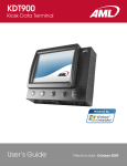
1
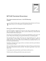
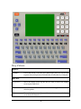
M7140
Desktop Terminal
User’s Guide
© 2007 American Microsystems LTD.
Effective date: March 2005
Website: www.amltd.com
M7140 DESKTOP TERMINAL
User’s Guide
Disclaimer
American Microsystems, Ltd. reserves the right to make changes in specifications and other information contained in this
document without prior notice, and the reader should in all cases consult American Microsystems, Ltd. to determine
whether any such changes have been made. The information in this publication does not represent a commitment on the
part of American Microsystems, Ltd.
American Microsystems, Ltd. shall not be liable for technical or editorial errors or omissions contained herein; nor for
incidental or consequential damages resulting from the furnishing, performance, or use of this material.
This document contains proprietary information which is protected by copyright.
All rights are reserved. No part of this document may be photocopied, reproduced, or translated into another language
without the prior written consent of American Microsystems, Ltd.
FCC Declaration of Conformity
Product Name: Model 7140 Desktop Terminal
Model Number: M7140
Radio Frequency Interference Requirements
This equipment complies with Part 15 of the FCC Rules. Operation is subject to the following two conditions: (1) This equipment
may not cause harmful interference, and (2) this equipment must accept any interference received, including interference that may
cause undesired operation.
This equipment has been tested and found to comply with the limits for a Class A digital device, pursuant to Part 15 of the FCC
Rules. These limits are designed to provide reasonable protection against harmful interference when the equipment is operated in
a residential environment. This equipment generates uses and can radiate radio frequency energy, and if not installed and used in
accordance with the instructions, may cause harmful interference to radio communications. However, there is no guarantee that
interference will not occur in a particular installation. If you determine the equipment does cause harmful interference to radio or
television reception (this may be determined by monitoring the interference while turning the equipment off and on), you are
encouraged to try to correct the interference by one of the following measures:
•
•
•
•
Reorient or relocate the receiving antenna.
Increase the separation between the equipment and receiver.
Connect the equipment into an outlet on a circuit different from that to which the receiver is connected.
Consult the dealer or an experienced radio or TV technician for help.
Changes or modifications not expressly approved by American Microsystems, Ltd. could void the user's authority to
operate the equipment.
Normalización y Certificación Electronica (NYCE)
Safety
NOM / NYCE-NOM-019-SCFI-1998
Safety of data processing equipment.
© 2005 American Microsystems, Ltd. All rights reserved.
2190 Regal Parkway • Euless, TX 76040
Phone 817.571.9015 • Fax 817.571.6176
Web Address: www.amltd.com
TABLE OF CONTENTS
INTRODUCING THE M7140
1
What to Expect
1
Network Settings
22
Warranty
2
Radio Settings
24
General Conventions
2
Host Server List
28
Terminal Options
29
M7140 TERMINAL OVERVIEW
3
Save Settings
32
Using the M7140 Keyboard
3
Diagnostic Menu
33
Key Values
4
RF Signal Strength
33
The M7140 Display Screen
6
Ping Server
35
The Optional M7140 Radio
7
Print Test Label
36
802.11b Fallback Mode
7
Firmware Version
37
Interference and Coexistence
7
Security Issues
7
Real time Clock
38
Ad-Hoc Mode
8
Serial Port Configuration
39
Network Setup
Local Settings
22
38
The Optional M7140 Tethered Scanner
10
Startup Options
40
Installing an Optional Tethered Scanner
10
Audio Settings
41
The Optional M7140 Bracket
11
Installing the M7140 Bracket
11
Linux Prompt
42
Journaling Flash File System
42
The M7140 Back Panel
12
FTP
42
The M7140 Communication Ports
15
Tools/Utilities
43
THE M7140 SERVER LOGIN
16
The CommandLink™ Software
Calculator
43
Basic
44
16
SmallBASIC
45
Wait WLAN
16
Set/Change Password
46
Connecting
17
Clear Password
46
Login
17
Applications
18
Telnet
18
THE M7140 ADVANCED FEATURES
47
Switching virtual consoles
18
File Transfer Protocol (FTP)
47
Terminal Emulation
19
The M7140 Web Server Application
47
Updating Firmware
20
The M7140 Memory Allocation
47
The Links Web Browser Application
50
THE M7140 MENU SYSTEM
21
3270 and 5250 TE Clients
52
Main Menu
21
The M7140 Tool Chain
52
Reconnect
21
Index
53
G E T T I N G
S T A R T E D
1
Chapter
Introducing the M7140
This chapter describes how to get started using your M7140 desktop
terminal and get you up and running fast.
M7140 desktop terminal is an ultra-versatile, high-performance, compact desktop
T heterminal.
It is rugged, requires a limited amount of desktop space, and is easy-to-use. The
high resolution graphical display is capable of presenting a multitude of fonts and images.
The M7140 utilizes a true, fully functional, Linux operating system. The Linux operating
system is well known for its stability, speed and conservative memory usage. The Linux
operating system coupled with the M7140’s high speed processor makes the M7140 one of
the fastest desktop terminals on the market today. In test after test the Linux operating system
has out-performed DOS based and Windows based operating systems when compared on
similar hardware platforms.
The M7140 is easy to use and program. Our specifically designed CommandLink™ software
makes it easy to create custom applications for any requirement. Our terminal emulation
software makes it easy to integrate the M7140 into legacy applications as well. You can even
utilize standard BASIC software on the M7140 desktop terminal.
What to Expect
This user’s guide provides you with an overall physical description, keypad values, technical
specifications and performance capabilities of the M7140 desktop terminal. In addition you
will learn how to:
•
Connect to your host computer
•
Customize your M7140 Terminal
•
Create and execute programs
•
Collect and upload data
•
Send and receive data
1
G E T T I N G
•
S T A R T E D
Connect and use the M7140 serial interface
Warranty
A one-year warranty against material defects and workmanship from the date of shipment is
guaranteed by American Microsystems, Ltd. Products are sold on the basis of specifications
applicable at the time of manufacture. American Microsystems, Ltd. shall have no obligation
to modify or update products once sold. At our option, we will repair or replace, at no charge,
any unit that proves to be defective providing the appropriate steps are taken to procure an
RMA (Return Materials Authorization) number and shipping instructions from American
Microsystems, Ltd.
General Conventions
Before you begin to use the M7140 terminal, it’s important that you understand key
conventions and terms used in this manual.
Keys
Description
SMALL CAPS
Refers to a specific menu selection contained in the M7140 in order to
continue or complete a task.
[KEY]
The square brackets indicate a specific key on the M7140 desktop
terminal’s key pad.
Bold
Words you type – for example when you are instructed to type
A:\setup. Bold also refers to existing filenames.
Italic
¤Notes
Italic/Bold
Warning! And section references.
Click/Select
After selecting a procedure or menu, “Click” means to press and
release the left mouse button. “Select” means that after you select the
menu item or action, you should press ENTER.
2
2
Chapter
M7140 Terminal Overview
This chapter describes the features of the M7140 desktop
terminal.
T
o save time in the future, print a copy of this document. Choose Print from the File menu,
and press Enter to receive all the pages of examples and instructions.
Using the M7140 Keyboard
The M7140 Terminal is equipped with seventy-seven keys that are divided into White, grey,
blue, red and black keys. When pressed, each key emits an audible beep to indicate that the
M7140 terminal has detected the key press.
The red power key turns the M7140 on/off. You must press and hold this key down to power off
the unit. This prevents accidentally powering off the unit if this key is momentarily pressed.
The twenty-four blue keys consist of four arrow keys, twelve function keys (F1 – F12), an
escape key (ESC), a tab key (TAB) a caps lock key (CAPS), two shift keys (SHIFT), an
alternate and control key (ALT) (CTRL) and one [ENTER] key (an additional enter key is on
the numeric keypad described later).
The shift keys will toggle between upper and lower case characters and selects special characters
on the alpha-numeric keypad.
There are ten black numeric keys with a backspace key on the end. There are ten white numeric
keys with one white period key and one enter key. The numeric keypad makes it easy to enter
numeric data.
Twenty-eight grey keys represent letters, special characters, and the space key.
The black menu key will bring up the built-in menu system at any time.
3
Key Values
Red Key
POWER
Powers unit off/on. You must press and hold the power key for the unit
to power down, this prevents accidental shut off when the key is bumped.
Blue Keys
5 (Up arrow)
Moves the display screen up one line at a time or moves the display
screen up one menu level.
3 (Left arrow)
Moves the cursor left one character at a time and toggles between menu
selection options.
6 (Down arrow)
Moves the display screen down one line at a time or moves the display
screen down one menu level.
4
screen down one menu level.
4 (Right arrow)
Moves the cursor right one character at a time and toggles between menu
selection options.
F1 – F12
Selects special functions determined by the host system.
ESC
Exits operation being performed
TAB
Tabs cursor to the next field.
CAPS
Toggles the capitalization mode on/off.
ENTER
Performs the Enter function.
SHIFT
Selects upper and lower case characters, depending on the CAPS lock
setting. SHIFT also selects the special characters on the numeric keypad.
ALT
Modifies the key for the Alternate key function.
CTRL
Modifies the key for the Control key function
Black Keys
MENU
Activates the built-in menu functions.
Numeric
1, 2, 3, 4, 5, 6, 7, 8, 9, 0.
? ¦
Deletes characters at the cursor position or if cursor follows a string of
characters, it deletes the characters to the left of the cursor
Grey Keys
Alpha
Letters A-Z and special characters when ALT key is pressed prior to
letter key.
Space
Enters the space character
White Keys
Numeric
1, 2, 3, 4, 5, 6, 7, 8, 9, 0, . (period) and Enter.
Use the ALT and SHIFT combination to select the
special characters shown on the alpha keys. Use
5
just the SHIFT key to select the special characters
on the numeric keys.
The M7140 Display Screen
The M7140 desktop terminal includes a 320 pixel by 240 pixel grayscale graphical
Liquid Crystal Display (LCD). Programs can be written which mix text and graphics
together on the display.
Warning: This display is NOT a touch screen display and the operator should not use
sharp objects on the plastic window protecting the LCD display.
The contrast on the M7140 display can be adjusted
for different lighting and for viewing at different
angles. The knob on the back of the M7140 case
adjusts the contrast of the display.
6
The Optional M7140 Radio
The M7140 desktop terminal can be purchased with an optional 802.11b radio and antenna. This
radio is specifically designed to communicate with any 802.11b Access Point. The range of the
radio depends greatly on the quality of the Access Point and the RF communications
characteristic of the environment where the device is used. The typical range for an 802.11b
radio is 500 feet through free air. Additional Access Points must be added to improve coverage
in a larger area, or in electrically noisy RF environments.
802.11b Fallback Mode
Wireless LAN technology is designed to make maintaining a connection between two devices
as reliable and consistent as possible. Since the speed of the connection between wireless
devices will vary as range and signal quality varies, the wireless devices will intentionally
sacrifice throughput (data rate or connection speed as measured in bits per second) in exchange
for maintaining a reliable connection. In other words, a reliable connection at a lower speed is
preferred over an unreliable connection at a higher speed (i.e., it is easier to maintain the
connection if data rate is deliberately reduced, or put another way, lower data rates will tolerate a
higher range and/or worse signal quality). This characteristic is known as fallback. As example,
an 802.11b system will fallback from 11 Mbps to 5.5 Mbps as range increases or signal quality
decreases. Subsequent fallbacks from 5.5 Mbps to 2 Mbps and 1 Mbps are also supported
Interference and Coexistence
802.11b operates in a range of radio frequencies known as an "unlicensed" band (i.e. the FCC
does NOT require the use of a license in order to operate a radio transmitter in this range). This
means that commercially available radio devices other than wireless LAN devices are permitted
to use the same frequency band as 802.11b. Consequently, these co-existing radio devices can
interfere or "jam" the wireless LAN (and vice versa). Ironically, the most troublesome devices
are cordless telephones and microwave ovens.
Fortunately, higher quality cordless phones tend to "listen" for a clear channel before becoming
active and will thus avoid interfering with a wireless LAN (i.e., the cordless phone seeks a clear
channel for itself so naturally avoids being interfered with or being a source of interference).
Jamming from microwave ovens is more severe but is usually restricted to the upper frequency
range for 802.11b (it should be noted that 802.11b divides the available frequency band into 11
channels. The higher numbered channels are most susceptible to microwave oven interference).
In each instance, jamming occurs only when the cordless telephone or microwave oven is
active.
Security Issues
Much has been publicized in the mass media recently about security problems with wireless
LANs. Although it cannot be denied that the encryption algorithms currently used in 802.11b
7
are flawed, the fact is that security breaches of a wireless LAN require a deliberate attempt to
access the network by an intruder.
The primary issue is that many current users of wireless LAN have opted NOT to turn on
security features. If users were to enable the security features currently available (including only
allowing known systems access to the network and enabling WEP (Wired Equivalent Privacy)
encryption the intruder's work is much harder. Much as a burglar will bypass a house whose
doors and windows are securely locked, so too will a hacker tend to bypass a network where
security measures are enabled.
Ad-Hoc Mode
Most installed wireless LANs today utilize "infrastructure" mode that requires the use of one or
more access points. With this configuration, the access point provides an interface to a
distribution system (e.g., Ethernet), which enables wireless users to utilize the corporate network
and the CommandLink server.
As an optional feature, however, the 802.11b standard specifies "ad-hoc" mode, which allows
the radio network interface card (NIC) to operate in what the standard refers to as an
independent basic service set (IBSS) network configuration. With an IBSS, there are no access
points. User devices communicate directly with each other in a peer-to-peer manner.
The next illustration shows the M7140 desktop terminal using Ad-hoc mode.
The next illustration shows the M7140 desktop terminal in a typical wireless network.
8
Typical Wireless Network
Desktop
terminal
(M7140)
Wireless Access
Point(s)
(802.11b)
Ethernet
Connectio
n
Personal
Computer
(Server)
Handheld
terminals
(M7100)
9
The Optional M7140 Tethered Scanner
The M7140 has an optional handheld tethered scanner. This scanner is attached through the
serial port. Most serial scanners require an additional power supply.
Installing an Optional Tethered Scanner
In order to install the Optional Tethered Scanner for the M7140 you must follow these steps.
1. The scanner type must be a decoded serial keyboard wedge.
2. The scanner must have its own external power supply.
3. The serial port must be set to “scanner”.
10
The Optional M7140 Bracket
The M7140 has an optional Mounting Bracket for users who need to mount the unit on a wall or
have more of an angle for a desktop. The M7140 Mounting Bracket is secured to the M7140
terminal by 2 screws. There are mounting holes for easy wall mount.
Installing the M7140 Bracket
To install the M7140 bracket, be sure the top and bottom middle screws are removed from the
inside of the M7140 terminal. Use the 2 supplied screws in these top and bottom holes. Either
mount the unit to a wall or use the bracket for a desktop bracket. The bracket can also be used
reversed when the unit is mounted high on the wall.
11
The M7140 Back Panel
The M7140 has several types of ports on the back of the unit.
The ports are shown here.
I/O Port
Power
Audio Port
RS232-1
RS232-2
CF Port
LCD Contrast
USB Slave
Ethernet
The description of these items is listed below.
12
Description of the Power Connector
Use only an American Microsystems, Ltd. approved power supply; output rated 5
VDC and a minimum of 2 Amps. The power supply connects to the M7140 by a
2.1mm x 5.5mm barrel connector, center positive.
1. 5 VDC
2. GND
Description of the I/O Connector (DB-15 Male)
1. Input 2-B
2. Input 1-B
3. Input 0-B
4. Relay 2 (NO)
5. Relay 2 (NC)
6. Relay 1 (Contact)
7. Relay 0 (NO)
8. Relay 0 (NC)
9. Input 2-A
10. Input 1-A
11. Input 0-A
12. Relay 2 (Contact)
13. Relay 1 (NO)
14. Relay 1 (NC)
15. Relay 0 (Contact)
Description of the Audio Connector
1. Audio Out
2. Audio In
3. GND
Description of the RS-232-1 Port (DB-9 Male)
1. DCD
2. RxD (in to terminal)
3. TxD (out from terminal)
4. DTR (out from terminal)
5. GND
6. DSR (in to terminal)
7. RTS (out from terminal)
8. CTS (in to terminal)
9. 5 VDC (out from terminal)
13
Description of the RS-232-2 Port (DB-9 Male)
1. DCD
2. RxD (in to terminal)
3. TxD (out from terminal)
4. DTR (out from terminal)
5. GND
6. DSR (in to terminal)
7. RTS (out from terminal)
8. CTS (in to terminal)
9. 5 VDC (out from terminal)
Description of the Compact Flash Port (CF Card)
1. Compact Flash Port (external)
Description of the LCD Contrast Adjustment (Knob)
1. LCD Contrast Adjustment Knob
Description of the USB Port (Type II - Slave only)
1. 5 VDC
2. Data 3. Data +
4. GND
Description of the Ethernet Port (RJ-45 8 Pin)
1. TX +
2. TX 3. RX +
4. GND
5. GND
6. RX7. GND
8. GND
14
The M7140 Communication Ports
The M7140 desktop terminal has 2 different styles of communications ports, RS-232 (DB-9
Male) and USB Slave Port (Type II). The two RS-232 connectors are used as standard serial
ports for external scanners, printers and serial communications.
The USB Slave port is a high speed connection to a standard PC, to load the M7140 operating
system. It can not be used to connect to other USB slave devices such as printers and scanners.
Both RS-232 communication connectors on the back of the M7140 desktop terminal are wired
as a DCE (Data Communications Equipment) device. This means that the communications
protocol used on the M7140 desktop terminal is the same as if it were a standard computer. The
M7140 desktop terminal has no internal RS-232 jumpers or switches that can be manually
changed. All RS-232 setup is done using the M7140 Menu System.
The slower RS-232 communication port is primarily used for uploading and downloading of
data files to the M7140 Batch desktop terminal. File transfers for the M7140 RF desktop
terminal can be done using FTP. For more information on FTP see the “FTP” section of this
manual.
The high speed USB data port is primarily used to load a new or updated operating system into
the M7140 desktop terminal. Use the AML USB Flash utility software to load the operating
system.
1
2
6
3
7
4
8
5
4
3
1
2
9
RS232 (DB-9 Male)
USB Type II (Slave)
DB-9 Pin out (RS-232)
1 – DCD (Data Carrier Detect)
6 – DSR (Data Set Ready)
2 – RXD (Receive Data)
7 – RTS (Request To Send)
3 – TXD (Transmit Data)
8 –CTS (Clear To Send)
4 – DTR (Data Terminal Ready)
9 – 5 VDC (Scanner Power Out)
5 - GND (Signal Ground)
15
3
Chapter
The M7140 Server Login
This chapter describes the login functions of the M7140
terminal. It also describes using Telnet and Terminal
Emulation support.
W
arning: If the M7140 Desktop terminal has improper security and/or network
settings, the terminal will fail to connect to any network devices. For help see
the Network Settings section of this manual.
The CommandLink™ Software
The CommandLink™ software allows a Windows based PC
to become a host server. A host server is a master control PC
that tells the M7140 desktop terminal what to display and
what to do with collected data. If your network already has a
host server then you may choose to login into that server.
Many servers use a Telnet session to connect them to their
client devices. By default, the M7140 starts a telnet session
when it is first turned on. For more information about telnet,
see the Telnet section of this chapter.
Wait WLAN
The following screen shows the M7140 desktop terminal waiting to find a Wireless Local
Area Network (WLAN).
16
If there is not a wireless Access Point (AP) for the desktop terminal to connect to, then the
terminal will not proceed past this point. For help in determining the presence and strength of
an Access Point’s transmission see the Network Diagnostics section of this manual.
Connecting
The following screen shows the M7140 desktop terminal connected to an Access Point. The
MAC address number for the access point is displayed at the bottom of the screen. After the
M7140 desktop terminal connects (associates) with an access point, it attempts to connect to
an active CommandLink™ Server.
If there is not an RF Server active for the M7140 desktop terminal to connect to, then the
terminal will not proceed past this point.
Login
The following graphic shows a typical login screen for the CommandLink™ RF server. If you
are using your own server, the login screen will be different. For help in determining the
presence of a CommandLink™ Server see the CommandLink™ documentation.
If the User ID or Password is not listed on the CommandLink™ database a Login Error screen
will appear.
17
Applications
If you are using the CommandLink™ software, and the proper User ID and Password are
entered, then the Applications Menu is displayed. These are the programs that are available on
the CommandLink™ Server for this user. Other users may see other programs depending on
the settings in the CommandLink™ Administrator.
If no application is chosen, then the connection will be closed.
Additional programs can be created and modified by using the CommandLink™ Developer.
Refer to the CommandLink™ documentation for instructions on how to use the
CommandLink™ software.
Telnet
For users who have their own Telnet applications, the M7140 desktop terminal can be setup to
simply run a telnet session.
In the above examples, it was assumed that the M7140 would be connecting to a
CommandLink™ host server. If you would like to connect to your own telnet server, the
procedure is exactly the same. To run your telnet session you would simply enter the IP
address of your telnet server. An instruction on setting the IP address is explained under the
section “Connection Settings” of this manual.
Once the M7140 desktop terminal has successfully attached to a wireless network, it
automatically attempts to start a telnet session. The server address and parameters for making
this connection are listed under the Connection Settings menu of the M7140 desktop terminal.
Switching virtual consoles
The LCD screen and the keyboard are collectively referred to as the console. To let you
interact with several applications all at once, the M7140 permits multiple sessions to be run
concurrently on consoles by means of virtual consoles. The virtual consoles are defined as
follows:
Console 1: Menus
Console 2: Communications Session or User Program
18
Console 3:
Console 4:
Console 5:
Console 6:
Console 7:
Console 8:
Console 9:
RESERVED
User Defined
Linux prompt
User Defined
RESERVED
User Defined
RESERVED
Each virtual console is running a different foreground application that uses the entire
screen. The keyboard is attached to the virtual console that's currently visible. You can
switch from one virtual console to another - and thus from one application to another - by
entering the following key strokes.
To switch to a different console, press the Alt,
Func, and a number key corresponding to the
Console number. The keys should be pressed one
key at a time, not all at once.
Terminal Emulation
The M7140 desktop terminal has three types of terminal emulation software installed as
default. They are amlterm, VT100 and VT220. There is also a Custom option which is
described later.
The amlterm terminal emulation software is specifically designed to work with the
CommandLink™ software. The CommandLink™ software controls the functionality of the
terminal from the CommandLink™ host server. The CommandLink™ host server runs on a
Windows based PC connected to the same LAN as the access points. In this mode the
CommandLink™ host server controls all of the terminal’s functions.
The VT100 and VT220 terminal emulation is for other types of host servers. When using
these two terminal emulation software types, the menus change to allow the terminal to be
setup manually to perform custom features such as font size, scrolling options and virtual
display size.
The Custom option allows you to set a custom terminal name for the M7140 which will be
sent to the server during connection. The terminal emulation will still be set to VT220.
The expanded memory version of the M7140 supports 5250 and 3270 terminal emulation with
optional software. Custom screen mapping and keyboard redefinitions are also possible with
this optional software.
19
The M7140 has a built-in feature which makes it easy to see when the terminal is out of range
of an access point. When the M7140 goes outside of RF coverage, the following screen
appears. When the operator goes back into RF coverage, the “Out of Range” screen will
automatically disappear and return the operator to where they left off. This feature is only
available when using the built-in terminal emulations described above.
Instructions on selecting the terminal emulation type are described in the Connection Settings
section of Chapter 4.
Updating Firmware
The M7140 has a built-in web server function which makes updating the firmware very
simple. The M7140 desktop terminal can be flash over the RF network using a standard web
browser, for example Internet Explorer. The files will be transferred to the M7140 unit over
the RF link and no cables or other software is required.
To upgrade the M7140 firmware, the unit must be on, and connected to the same network as
your PC. Open your internet web browser and type the IP address of your M7140 desktop
terminal into the Address box. Once you have successfully connected to the M7140 you will
see a green AML screen (this is generated and sent to your PC by your M7140 unit). Select
the "Reprogram Device Firmware" link. At the bottom of this page, you will see several file
options. For each file type, use the radio button to select the type of file being flashed, then
attach the file using the browse button (do not unzip the "rdiskxx.gz" file for this operation).
Finally, click Submit to start the process (do not turn the power off on your M7140 until the
flash process is completed). When finished, the unit will either create a green OK screen or a
red error screen based on the results. If there are errors, try sending the file again before power
cycling the M7140.
The latest firmware files can be downloaded off
the AML website at: www.amltd.com
20
4
Chapter
The M7140 Menu System
This chapter describes the Main Menu functions of the M7140 desktop
terminal.
Main Menu
Y
ou may access the menu system by pressing the [Menu] key on the M7140 desktop
terminal. The menu screens pop-up in front of the currently displayed screen. Only the
items in the menu screens are active when the menu items are displayed.
The menus can be navigated by using the up and down cursor keys. A selection is made by
pressing the [ENTER] key on the M7140 desktop terminal. The [ESC] key will always exit
the current menu.
Reconnect
The reconnect option forces the handheld to reconnect to the CommandLink™ RF server.
This is useful if the connection is stalled for whatever reason.
21
Network Setup
By selecting the Network Setup function from the Main Menu the wireless network adapter
can be configured. The “Network Connection Info” dialog box displays the current IP Address
(IP), Network Mask (MASK), MAC Address (MAC) and RF Status (RF) of the wireless
Ethernet card that is installed in the M7140. The RF Status is described in more detail in the
Diagnostics portion of this manual.
Network Settings
The standard network settings are changed by hitting the [ENTER] key while the Network
Settings menu item is highlighted.
In this screen you can see the current network information. In the above example screen, the
IP address of the M7140 is currently set to 192.168.100.111 and the network mask is the
typical 255.255.255.0. The MAC address of the network adaptor that is currently installed is
00:60:B3:6A:00:57. The M7140 is currently connected using an RF adaptor to an Access
Point (AP).
The M7140 desktop terminal can use a standard 100BaseT (fast Ethernet) wired connection,
or it can use a Compact Flash radio card (802.11b). You must select which style network you
will be using.
By hitting ENTER the user can select the Network Settings screen. The user will a screen
shown similar to the one below.
22
If a static IP address is to be assigned to the M7140 desktop terminal, then the Static button
should be selected. Static IP addresses should only be assigned by the Network Administrator.
IP address conflicts can occur if the wrong IP address is assigned.
If the local area network has a Dynamic Host Configuration Protocol (DHCP) server attached
to the network, then the DHCP function can be used. To select the DHCP function, simply use
the arrow keys to highlight the DHCP button. If your network uses the BOOTP protocol then
highlight that button. Note that when using DHCP or BOOTP, several of the items below are
missing. This is because the DHCP server or the BOOTP server will automatically assign
these values. If the wireless WLAN does not use the DHCP or BOOTP functions, then the
user must type in the appropriate values for the M7140 desktop terminal to communicate.
23
Warning: These values are unique for each network and are assigned by your local
Systems Administrator. Improperly setting these functions or values will cause the M7140
to fail to communicate and can cause problems with other network devices.
Note: Enabling DHCP or BOOTP will cause the M7140 desktop terminal to take slightly
longer to establish a connection to the RF network due to the overhead involved in obtaining
network information from the server.
Radio Settings
The Radio Settings allows the operator to set wireless network security settings.
The first radio setting is SSID (Service Set Identifier), a 32 character unique identifier attached
to the header of packets sent over a WLAN that acts as a password when a mobile device tries
to connect to the network. The SSID differentiates one WLAN from another, so all access
points and all devices attempting to connect to a specific WLAN must use the same
SSID. The SSID is CASE sensitive.
You can leave the SSID blank and the M7140 will match to any access point regardless of its
SSID as long as the WEP settings match. Because an SSID can be “sniffed” in plain text from
a transmitted data packet it does not supply any security to the network.
An SSID is also referred to as a Network Name because essentially it is a name that identifies
a wireless network.
24
In the example above, “AML Network” was chosen for the unique SSID name. Your unique
name should be assigned by your local Network Administrator.
The wireless security settings are referred to as WEP (Wireless Equivalent Privacy) can be left
un-enabled or can be enabled from this menu. It is HIGHLY recommended that some sort
of WEP standards be enabled in any wireless network. This information is unique for each
network and should be assigned by the local Systems Administrator.
The M7140 desktop terminal supports both 40 bit and 128 bit WEP key encryption. Note that
the number of key sets change according to which format is chosen.
The Key ID determines which key set is currently in use. Only the Key ID set selected will be
used, all other key sets are ignored.
25
To modify an encryption key set simply highlight the appropriate key set. Note that the
number of key pairs will change depending on which encryption format you are using.
Note: Some manufacturers will call their 40 bit encryption 64 bit encryption or call their 128
bit encryption 160 bit encryption; in any case they are the same settings. Also some
manufacturers will number their keys 1 to 4; these keys match the 0 to 3 keys on the M7140.
The current key set MUST match exactly, in the
same sequence, the key set that is currently
enabled in the Access Points, and be the same
key set listed in the “Key ID” field.
The Mode setting determines what type of network is in use.
The Infrastructure Mode is for connecting the M7140 Desktop terminal to a network of access
points. The Ad Hoc Mode is used for connecting the M7140 to a single access point or a
single radio card in a peer-to-peer network, such as a single laptop computer for example. The
M7140 will not have access to network resources in Ad Hoc mode.
26
The Auth setting determines what type of network system you are using.
These two modes simply define how the above key sets will be used to encrypt the data sent
over the radio. Whichever mode is selected, the access point MUST be set to the same mode
for communications to take place.
The Power Save setting will force the radio card to turn off when not in use to save power. If
you experience connection problems, turn the Power Save feature off. Battery life will be
shortened with the Power Save feature shutoff.
The Channel setting determines which channel the radio card will start to communicate on.
This should be set to the same channel as the access points.
27
Host Server List
The Connection Settings determine how the M7140 Desktop terminal will communicate to a
host server over the network. When the M7140 Desktop terminal first powers up, it tries to
establish a connection to an RF or standard network. If this is successful, it will then start a
Telnet session using the settings described in this section.
During this start-up process, the M7140 will look to see if multiple host servers have been
defined in the Host Server List. If only one server is defined, the M7140 will proceed to
attempt to establish a connection with that server. However, if more than one host server has
been defined, the user will be prompted to choose a host server name from a list of servers.
If multiple host have been defined, and a user wishes to select a different host, then the user
would hit the Menu key then Reconnect and the host list will be re-displayed. The user should
then simply select the host they wish to connect to.
When defining hosts servers, names can be any combination of letters and numbers, up to 15
characters long. The Port setting determines which network port the M7140 desktop terminal
will try to connect to. The default setting is Port 23 but some network systems require this to
be changed.
If the AML CommandLink™ RF software is being used with your network, then the IP
address of the CommandLink™ RF server must be supplied. This is the IP address of the
computer where the CommandLink™ Communicator is running.
28
The M7140 Desktop terminal has optional Terminal Emulation software available that enables
it to communicate directly with most host systems including IBM mainframe and IBM AS400
systems. This software has many more features than described in this manual.
Terminal Options
The Term setting determines what terminal type the M7140 will emulate. The default setting
is “amlterm” which is a superset of VT100 Terminal Emulation. If you are using
CommandLink™ software, set the Terminal type to amlterm. When using amlterm with
CommandLink™, the optional features are controlled by the CommandLink™ server.
The Local Echo feature enables or disables displaying of characters sent to the host system.
The default setting for most host systems is Local Echo disabled (unchecked).
The “amlterm” emulation is designed to be used with the AML CommandLink™ software.
Using this emulation with host servers designed for other types of emulation, will produce
unexpected results.
The “vt100” and “vt220” terminal emulations are a standard type of emulation typically used
with UNIX based host servers.
The “custom” selection allows the user to modify the “vt100” emulation for custom
applications. This emulation is rarely used.
The M7140 supports other types of terminal emulations using optional software.
29
If a different terminal type is selected, then the optional features for that emulation are
displayed. These features allow you to customize how the M7140 desktop terminal will
display the information from your host server.
The Font function allows you to select a custom font size which will change the amount of
information displayed on the screen.
If the Disable Scrolling check box is checked the screens will lock into the upper left hand
corner of the display regardless of how much information is sent to the screen. This box is
unchecked by default.
30
If the Virtual 24x80 check box is unchecked all the text sent to the terminal will be squeezed
into the current display size (which depends on the font size selected). Most terminal
emulation screens are written for a 24 column by 80 character display size so this box is
checked by default.
If the Follow Cursor check box is checked then the screen will scroll to wherever the cursor is
on the display. This box is unchecked by default.
The Col Shift function determines how many columns the display will move each time the
Shift <arrow> keys are used. This allows the operator to “pan around” the currently displayed
screen. Use the left 3and 4right arrow keys to change this setting.
31
The Row Shift function determines how many rows the display will move each time the Shift
<arrow> keys are used. This allows the operator to “pan around” the currently displayed
screen. Use the left 3and 4right arrow keys to change this setting.
Save Settings
The <Save Settings> function allows the new network settings to be permanently stored in the
M7140 desktop terminal’s non-volatile memory.
If you do not save your settings they will be lost
when you exit the Network Settings screen.
The terminal options will only be made permanent
if you do a Save Settings, otherwise they are lost
when the unit is turned off and on.
32
Diagnostic Menu
The “Diagnostic Menu” has several powerful functions that can help pinpoint a variety of
network problems. The Diagnostic menu can be used to determine connectivity to the network
as well as connectivity to the server or host computer.
RF Signal Strength
If the optional RF card is installed, the “RF Signal Strength” function allows the operator to
test the RF Link Status.
The “RF Quality” bar graph shows the RF signal strength of the closest Access Point. If this
bar graph is at 0% then there is no active Access Point in the area or your network settings are
wrong. Obviously the M7140 desktop terminal can not function without a good quality signal
from an Access Point.
The “Avg. Signal” bar graph indicates how much of the RF signal being received is usable. As
this percentage lowers, so will the TX Rate.
The “Avg. Noise” bar graph indicates how much of the RF signal is un-unusable. If the RF
signal is too low or the RF noise is too high, the M7140 desktop terminal will perform much
more slowly or not at all.
33
The “WLAN:” shows the current connection status reported by the internal RF card. This
status can be a very useful tool to determine if an RF connection is being made. The
description of this status is shown below:
Disabled
This normally means that either network settings are
being changed or the RF card is malfunctioning or not
making contact.
Searching
This can appear in these types of situations:
1.
2.
3.
4.
No access point at all.
There is no RF coverage in this area.
The SSID is set wrong.
The WEP is wrong and the authorization is set to
SharedKey.
Connected - Ad Hoc
This is when the M7140 is connected to one and only
one RF card in a peer-to-peer mode (like a laptop PC
RF card).
Connected - AP
Normally this means everything is OK and the user
should be able to communicate. It is possible that the
WEP settings are wrong but the authorization is set to
OpenSystem.
Out of Range
This means that there was a functioning connection
and the unit has gone out of range.
The “MAC: 00:40:05:DF:88:64” is the hardware address of the currently connected Access
Point. This address is unique to each Access Point used. In Ad-Hoc mode this will display
“N/A – Ad Hoc Mode”.
The “TX Rate” shows the speed in Mega-Bits per Second (Mbps) that the unit is currently
transferring data. The transfer speed will start at 11 Mbps and “fall-back” to lower speeds
depending on the RF strength and quality. This “fall-back” is automatic and can not be set by
the operator. If you find this speed to be unacceptably low, you must improve the wireless RF
network coverage in your area.
The “RF Strength” function can be used to test the
RF coverage of a wireless RF local area network.
34
Ping Server
The “Ping Server” function is a very powerful tool to test connectivity through the wireless RF
network.
When the “Ping Server” function is selected, the dialog box includes a section to type an IP
address on the bottom. Once a valid IP address is typed hit [ENTER] to start the “pinging”
process. Press the [ESC] key when finished.
The “Ping Status” screen will show the M7140 desktop terminal trying to contact the listed IP
Address. Once the connection is made the M7140 Desktop terminal will continuously send
packets of data to time the connection speed in milliseconds (ms). The “Ping Status” screen
will display the results of the ping process.
35
If the M7140 desktop terminal does not receive a response to the pinging, then the above
(right) screen will appear. It is very important that the M7140 desktop terminal is able to
communicate with the CommandLink™ RF communicator server PC. The “Avg” transfer
time in milliseconds and “PLoss” percentages is very important. High ping transfer rates or
failure to communicate with the server will make the CommandLink programs un-usable on
the M7140 desktop terminal.
The “Ping Server” function can be used to ping Access Points and other computers on the
wireless local area network. This is a useful tool in determining wireless network connectivity.
Like all computer equipment, the M7140 Desktop terminal can not ping to other equipment
that isn’t connected to the currently specified local area network.
Print Test Label
The “Print Test Label” function allows the operator test a serial printer through the port on the
back of the M7140 desktop terminal.
The types of printers supported are shown in the “Print Test Label” sub-menu function.
If the M7140 desktop terminal is setup for serial printing, it sends the data to the serial port
(see Local Settings Menu for communications options).
36
Firmware Version
The “Firmware Version” function displays the information about the M7140 desktop
terminals firmware version and the date and time it was created.
There are three parts to the M7140 firmware. The “Bootloader” which is a hardware level
memory and can only be reprogrammed at the factory. The “RAM Disk Image” is the built-in
software routines that control specific functions to the M7140 like the menu system. The
“Linux Kernel” is the standard Linux operating system that is found in other Linux based
devices.
The AML website (www.amltd.com) includes a support section that has the latest firmware
revisions. These revisions will have version numbers to indicate which is the latest available.
You MUST use only the M7140 firmware in this unit.
Please carefully check the firmware type before
you attempt to re-program the firmware in any
AML product.
37
Local Settings
The “Local Settings” function sets much of the M7140 desktop terminal’s internal hardware
and software.
Real time Clock
The “Real Time Clock” function sets the M7140 desktop terminal’s internal clock. These
setting are saved even if the unit is powered off.
You can hit the [ENTER] key to pop-up a calendar to make setting the date easier. You must
Save the settings for them to take effect.
38
Serial Port Configuration
The “Serial Port Configuration” function allows the operator to configure the local serial ports.
When the RS-232 port is selected, you must set up the port parameters.
Serial Port:
Open – No Connection, Available for use.
Barcode Scanner – Data received is routed to the keyboard buffer.
Serial Printer – Port in use for 2-way serial data transfer
Linux Console – Output Linux debugging and serial commands.
Baud:
115200 – 57600 – 38400 – 19200 – 9600 – 4800 – 2400 – 1200 - 300
Parity:
None – Even – Odd - Mark
Data Type:
None,8,1 – Even,8,1 – Odd,8,1 – None,7,1 – Even7,1 - Odd,7,1
None,7,2 – Even,7,2 – Odd,7,2 – None,8,2 – Even,8,2 – Odd,8,2
Flow Control: None - RTS/CTS – Xon/Xoff
<Save>
You must save the settings for them to take effect.
39
Startup Options
The “Startup Options” function allows the operator to setup various options used when the
M7140 is first powered on.
Basic Dir:
This specifies the directory listing used when the basic option is
selected from the Tools/Utilities menu.
Basic Mode:
This is the default mode that Basic programs will run under. This
mode can be changed at the Basic function prompt.
Start Dir:
This is the directory that the M7140 terminal will use for any auto-start
programs.
Start Prog:
This is the program the M7140 will automatically start when the unit
is powered on.
When a startup program is specified, the M7140 will not start the
internal telnet program.
Start Param:
These are any optional settings that the auto-start program will use
when started.
Network Delay:
This is the delay in milliseconds the M7140 will wait before starting
the auto-start program. This gives the network time to setup routers
and paths to the M7140.
Enable Servers
This allows you to disable network connectivity to the M7140. This is
usually used to keep the M7140 more secure over a network.
Disabling these functions will prevent file transfers and operating
system updates.
Do not disable the M7140 FTP server function if you are using the
CommandLink™ Host server.
40
Audio Settings
The “Audio Settings” function allows the operator to setup various options used for the
M7140 internal speaker or the audio jack port on the back of the unit.
Use the left 3and 4right arrow keys to adjust the volume.
41
Linux Prompt
The “Linux Prompt” function puts the M7140 desktop terminal into its native Linux
Operating System.
You can simply hit the Menu key to return to the M7140 Menu system.
Journaling Flash File System
The M7140 Desktop terminal includes the capability to save programs and data. There is a
special, non-volatile sub-directory to store user information. This sub-directory is jffs2 (lower
case only) and can be accessed from the Linux prompt by typing “cd jffs2”. You can list the
contents of this directory by typing “ls” (list).
FTP
You can easily upload and download to the M7140 Desktop terminal over the RF link by
using a File Transfer Program (FTP). These programs are readily available over the Internet.
In order to communicate with the M7140, it must be turned on, and you must know its current
IP address. Most FTP programs require you to supply the “IP address”, “User Name” and
“Password” for the connecting device.
The default user name is “aml” and the default password is “turk182” (case sensitive).
42
Tools/Utilities
The “Tools and Utilities” function includes the built-in Calculator and Basic interpreter
functions.
Calculator
The M7140 desktop terminal comes equipped with a powerful calculator utility “BC” which
can be activated from the Tools/Utilities menu.
The calculator can do simple mathematical functions by simply typing the data from the
keypad.
43
The calculator can do much more complicated math functions. Note that the functions require
the operand be in parentheses ( ).
Basic
The M7140 desktop terminal comes equipped with a BASIC interpreter.
The BASIC interpreter can be run in the Graphic (GFX) and Text (TXT) modes. Hit the
[ENTER] key to toggle screen mode.
44
To run a program simply scroll to the program name and hit [ENTER].
Note: Some BASIC programs end by themselves or you should just hit [ENTER] to quit.
Other programs must be interrupted by hitting the [Ctl] and [C] keys at the same time.
SmallBASIC
The M7140 desktop terminal uses a version of BASIC called SmallBASIC. Information about
SmallBASIC can be obtained on the internet at:
http://smallbasic.sourceforge.net
SmallBASIC (SB) is a simple computer language, featuring a simple interface, strong
mathematics and graphics.
SmallBASIC comes with ABSOLUTELY NO WARRANTY or support from American
Microsystems, Ltd.
The SmallBASIC program is free software; you can use it, redistribute it and/or modify it
under the terms of the GNU General Public License version 2 as published by the Free
Software Foundation.
45
Set/Change Password
The M7140 has the ability to set a password to prohibit unauthorized users from viewing or
altering the network settings and Local Settings.
Clear Password
To set the password simply type in any alphanumeric string and hit ENTER. To clear the
password simply type in the existing password and hit ENTER.
46
5
Chapter
The M7140 Advanced
Features
This chapter describes some of the advanced features of the M7140 Desktop terminal.
File Transfer Protocol (FTP)
The M7140 Desktop terminal includes a client side FTP program which makes it very easy to
upload and download files and data. Almost any computer using almost any FTP program can
send and receive files to and from the M7140 using the radio link. The “host” computer must
have a logical network connection to the M7140. This can be tested by either “pinging” the
M7140 or “pinging” the host from the M7140. See the M7140 User Manual for more details.
Once you have established connectivity you will need the M7140’s IP address, the user name
of “aml” and a password of “turk182” to start the FTP session. The current M7140 IP
address can be determined by using the M7140 menu system and selecting Network Settings”
The M7140 Web Server Application
The M7140 Desktop terminal includes a built-in web server which makes it incredibly easy to
upgrade the operating system or add a new startup splash screen. The “host” computer must
have a logical network connection to the M7140. This can be tested by either “pinging” the
M7140 or “pinging” the host from the M7140. See the M7140 User Manual for more details.
By opening any standard web browser (i.e. Internet Explorer), you can type in the M7140’s IP
address and the M7140 will send back a unique web page screen. By using this web page
screen you can update the Linux operating system or modify the startup splash screen. The
web page screen shows instructions on how this is done and update files can be downloaded
off the AML website www.amltd.com.
The M7140 Memory Allocation
To reduce cost and increase reliability, the M7140 does not have a mechanical hard drive like
a standard PC. All programs and data must be stored in the M7140’s electronic memory
devices. The M7140 has two types of electronic memory devices, Flash and RAM.
47
The RAM memory works much like a standard PC, The Linux operating system and any
programs currently being executed, are utilizing the RAM memory. Very large programs that
exceed the RAM memory storage size can not be executed on the M7140. Just like in a
standard PC, this RAM memory is lost when the unit is powered off. All permanent storage of
the operating system, programs and data must be done in the Flash memory.
Some of the Flash memory is used by the Linux operating system along with some associated
programs. On the expanded memory version of the M7140, there is a large percentage of
Flash memory available for user programs. These user programs are often added to the Linux
kernel and downloaded to the M7140 as one large memory block.
Sometimes the users will wish to add programs at a later date or store temporary data in the
Flash memory. The M7140 has a special sub-directory for all programs and data that are
temporary but must be saved even when the unit is turned off. This is the “Journaling Flash
File System” sub-directory also know as the “jffs2”.
Flash Memory – 4 MB
64K
832K
64K
64K
2.4MB
640K
RAM Memory – 16 MB
Boot Loader
Linux ZImage
Compressed Kernel
Splash Screen Bitmap
Boot Parameters
rdisk.gz
Compressed Linux Applications
7MB
Uncompressed (running)
Linux Kernel
1MB
Free User Memory (volatile)
6MB
Uncompressed (running)
Linux Applications
Root File System
2MB
Scratch Pad File System
Volatile File Memory Area
Free File Memory Area
jffs2 – Non-volatile File System
Note: The jffs2 sub-directory is the only
memory location that user files can be
saved, that will not be lost when the
power is turned off.
The M7140 Standard Memory Map
48
Flash Memory – 16 MB
128K
896K
Boot Loader
Linux ZImage
Compressed Kernel
128K
128K
6.7MB
Splash Screen Bitmap
Boot Parameters
rdisk.gz
Compressed Linux Applications
8MB
jffs2 – Non-volatile File System
User Available File Space
RAM Memory – 32 MB
11.5MB
Uncompressed (running)
Linux Kernel
4.5MB
Free User Memory (volatile)
12MB
Uncompressed (running)
Linux Applications
Root File System
4MB
Scratch Pad File System
Volatile File Memory Area
Free File Memory Area
Note: The jffs2 sub-directory is the only
memory location that user files can be
saved, that will not be lost when the
power is turned off.
49
The M7140 Expanded Memory Map
The Links Web Browser Application
The M7140 Expanded Memory version desktop terminal includes a fully functional web
browser application called “links”. The links program can be started by using the M7140
menu system and selecting the “Linux Prompt” and typing “links”. The optional “-g” turns
graphics mode on, if this option is left off then the browser will start in text mode and graphic
images will not be displayed. The screen shots below show the links program running on the
M7140.
Once the operator hits “ENTER” from the welcome screen then the control menu for the links
program is selected by hitting the “Esc” key. If the M7140 terminal has connectivity to the
internet, then the operator can type in any valid URL and the M7140 will display the web
page.
If there is no connectivity to the internet or if a
local firewall prohibits internet access, then the
M7140 will display a blank screen.
Once a web page is displayed, the operator can “pan around” the screen by using the “Shift”
key then an arrow key (? ? ? ? ). The thin bars on the right side and bottom of the M7140
display shows how far the screen has shifted from the top left corner.
50
Because the M7140 has a smaller screen than a standard PC, not much of the web page can be
displayed at one time. The links program has several options that can make navigating the web
page screen easier. To select these options go to View > Html options, using the links menu.
By changing “User font size” and “Scale all images by (%)” you can get more information on
one M7140 display screen.
The M7140 Desktop terminal can be setup to automatically start the links program and go
directly to a predetermined website. This is done by using the M7140 menu system and
selecting Local Settings > Startup Options. The following screen shots show the M7140 set up
to start the links program in the graphics mode and to go to the AML website.
51
Under “Start Dir
:” we have added the startup directory “/bin/”
Under “Start Prog :” we have added the startup program “links” (case sensitive).
Under “Start Param:” we have added the start parameters “-g www.amltd.com”
Remember to use the “<Save Settings>” to make your changes permanent.
We might also need to increase the “Network Delay:” to a larger value to give the network
time to connect to the internet and find the requested website. The user can also use the
M7140 menu system to force a “Reconnect” if the network is not ready when the M7140 is
first powered on.
3270 and 5250 TE Clients
The M7140 Expanded Memory version desktop terminal can run an optional 3270 or 5250
terminal emulation client from Connect Inc.
The 3270 and 5250 TE clients are typically used with IBM AS/400 and IBM mainframe
systems. This optional software allows the M7140 desktop terminal to work just like a
standard IBM workstation terminal but with a smaller display.
The Connect TE software also has the ability to re-format the larger IBM workstation display
screens into the smaller M7140 handheld screens. This process is referred to screen mapping,
screen formatting or screen scraping. The ability to re-format the keyboard is also included
with the Connect software as well as PC based terminal manager software.
The M7140 Tool Chain
The M7140 is supplied with open-source Linux as a standard feature. In accordance with the
open-source or GNU license, all the M7140 source code is available to any M7140 owner
upon request. To obtain a copy of this code simply request the Tool Chain CD.
The Tool Chain CD comes with a StrongARM-Linux-GCC cross compiler and source code
that can be used on any Intel Linux platform to cross-compile applications. Technical
information on using the Tool Chain are included.
52
Index
A
Access Point, 17
Applications Menu, 18
Audio Settings, 41
Avg. Noise, 33
Avg. Signal, 33
I
Interference, 7
Internal clock, 38
IP Address, 22
J
B
Basic, 44
Basic Dir, 40
BASIC interpreter, 44
Basic Mode, 40
Broadcast Address, 22
C
Calculator, 43
Calculator utility, 43
Calendar, 38
Connecting, 17
Connection Settings, 28
D
Diagnostic Menu, 33
Display Screen, 6, 7
Dynamic Host Configuration
Protocol, 23
Encryption key, 26
F
Fall-back, 34
Fallback Mode, 7
Firmware Version, 37
FTP, 42
G
Graphic (GFX), 44
Radio Settings, 24
Real time Clock, 38
Reconnect, 21
RF Link Status, 33
RF Quality, 33
RF Strength, 33
Journaling File System, 42
S
K
Key ID, 26
Key Values, 4
Keyboard, 3
L
Links Web Browser, 50
Linux Prompt, 42
Local Settings, 38
Login screen, 17
Security, 7
Serial Settings, 39
Set/Change Password, 46
Setting the date, 38
SmallBASIC, 45
SSID, 24
Start Dir, 40
Start Param, 40
Start Prog, 40
Startup Options, 40
T
M
MAC Address, 22
Main Menu, 21
Menu System, 21
N
E
R
Network Mask, 22
Network Setup, 22
O
Optional M7100 Handle, 11
P
Parity, 39
Ping Server, 35
Ping Status, 35
Pinging, 35
53
Telnet, 18
Terminal Options, 29
Terminal Overview, 3
Test Label, 36
Text (TXT), 44
Tools and Utilities, 43
TX Rate, 34
W
Warranty, 2
WEP key encryption, 25
Wireless Equivalent Privacy, 25
Wireless Local Area Network,
16