1
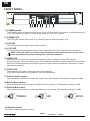
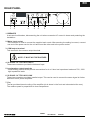
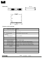
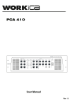
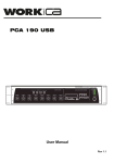
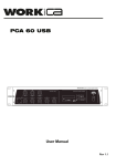
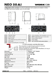
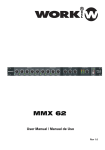
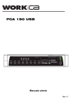
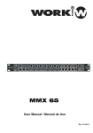
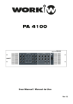
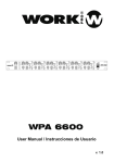
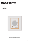
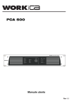
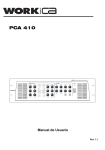
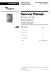
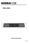
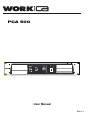
PCA 500
User Manual
Rev 1.1
EN
SAFETY RELATED SYMBOLS
WARNING:
TO REDUCE THE RISK OF FIRE OR
ELECTRIC SHOCK, DO NOT EXPOSE
TO RAIN OR HUMIDITY. DO NOT
REMOVE COVER. THIS PRODUCT IS
NOT INTENDED FOR USE OTHER THAN
STATED.
GRAPHICAL SYMBOLS EXPLANATION
This symbol, wherever used,alerts you to
the presence of un-isulated and dangerous
voltages within the product enclosure.
These are voltages that may be sufficient to
constitute the risk of electric shock.
External Connection
Always use proper ready-made insulated mains
cabling (power cord). Failure to do so could result
in shock or fire. If in doubt, seek advice from a
registered electrician.
Do not Remove Any Cover
This symbol, wherever used, alerts you to
important operating and maintenance
instructions. Please read.
Within the product are areas where high voltages
may be present. To reduce the risk of electric shock
do not remove any covers unless the AC mains
power cord is removed.
Protective Ground Terminal
AC mains (Alternating Current)
Covers should be removed by qualified service
personnel only.
No user serviciable parts inside.
Hazardous Live Terminal
ON: Denotes the product is turned on.
Fuse
OFF: Denotes the product is turned off.
WARNING
Describes precautions that should be observed to
prevent the possibility of death or injury to the user.
CAUTION
To prevent fire an damage to the product, use only
the recommended fuse type as indicated in this
manual. Do not short-circuit the fuse holder.
Before replacing fuse, make sure that the product
is OFF and disconnected from the AC outlet.
Protective Ground
Describes precautions that should be observed to
prevent damage to the product.
Before turning the product ON, make sure that it is
connected to Ground. This is to prevent the risk of
electric shock.
WARNING
Power Supply
Never cut internal or external Ground wires. Likewise,
never remove Ground wiring from the Protective
Ground Terminal.
Ensure that the mains source voltage (AC outlet)
matches the voltage rating of the product. Failure
to do so could result in damage to the product and
possibly the user.
Operating Conditions
Unplug the product before electrical storms occur
and when unused for long periods of time to reduce
the risk of electric shock or fire.
PAGE 1
Always install in accordance with the manufacturer´s
instructions.
To avoid the risk of electrtic shock and damage, do
not subject the product to any liquid/rain or moisture.
Do not use this product when in close proximity to
water.
Do not install this product near any direct heat source.
Do not block areas of ventilation.
User Manual
PCA 500
EN
FRONT PANEL
4 3 5 6 7
8 9
10
2
1
1). POWER switch
The POWER switch is used to turn the power of the unit on and off. The power is on when the switch is
in the "ON"position; the power is off when the switch is in the "OFF"position.
2). POWER LED
This LED lights up when the power is on; the LED goes off when the power is off.
3). SIG LED
This LED lights up when the output is above 200mV.
4). CLIP LED
The LED blinking indicates that the nominal level threshold of the input signal has been exceeded.
NOTE: If the clip LED is lit continuously immediately reduce the input level in order not to
reach high distortion levels or damage the connected speakers.
5). TEMP LED
When the unit is too hot, the temperature protection system engages and the LED lights up.
During protection, there is no signal output. The temperature protection system and LED will go off and
the unit will resume operation and output signal once again once the temperature has fallen to a safe
operating temperature.
6). PROT LED
The protection LED lights in the case of abnormal operation
(e.g. Output load short circuit protection or over load protection).
7). Built-in Treble control
Use a miniature screwdriver to adjust the Treble control as required. The adjustment range is ±12dB.
8).Built-in Bass control
Use a miniature screwdriver to adjust the Mid control as required. The adjustment range is ±12dB
9). Built-in Mid control
Use a miniature screwdriver to adjust the Mid control as required. The adjustment range is ±12dB.
0 dB
(Detent
position)
MID
+
+
+
TREBLE
-12 dB
+12 dB
+12 dB
+12 dB
0 dB
(Detent
position)
0 dB
(Detent
position)
-12 dB
10).Volume control
This knob is used to adjust the volume.
PAGE 2
User Manual
PCA 500
BASS
-12 dB
EN
REAR PANEL
1
2
3
4
5
7
6
1. BREAKER
It acts as circuit breaker, disconnecting the unit when excessive AC current is drawn and protecting the
installation.
2. Mains input socket
The connector is used to connect the supplied main cords. After assuring the setting is correct, connect
one end of the power cord to the unit and insert the other end to the power socket.
3. COM output terminal
This terminal is the common output terminal.
NOTE: IT MUST NOT BE EARTHED
4. XLR AND 1/4" TRS JACK INPUT
These two connectors provide the balanced input.
5. Loudspeaker output terminals
These binding post terminals provide connections for 4 or 8 ohm low impedance loads and 70V, 100V
high impedance loads.
6. XLR AND 1/4" TRS JACK LINK
These two connectors provide a parallel output. This can be used to connect the same signal to further
devices such as power amplifiers.
7. Fan
The fan provides internal cooling of the amplifier (air is drawn in the front and exhausted at the rear).
The rotation speed is proportional to inner temperature.
PAGE 3
User Manual
PCA 500
EN
DIMENSIONS
88 mm
400 mm
483 mm
TECHNICAL SPECIFICATIONS
Output Power (Rated)
480 W
INPUT
LINE (Impedance/Sensitivity)
Connection Type
20 k Ω / 1 V
XLR 3p female / Jack 1/4" socket
OUTPUTS
Direct Outputs
Connection Type
LINK Connection Type
Frequency Response
4, 8 Ω / 70, 100 V
Binding Post
XLR 3p male / Jack 1/4" socket
50 Hz ‐ 22 kHz +/‐ 3dB
EQ Control (Bass)
± 12 dB / 20 Hz ‐ 80 Hz /Centre frequency 30 Hz
EQ Control (Middle)
± 12 dB / 350 Hz ‐ 2 kHz /Centre frequency 800 Hz
EQ Control (Treble)
± 12 dB / 6.3 kHz ‐ 20 kHz /Centre frequency 16 kHz
S/N ratio
Main Supply AC power
> 90 dB
230 V - 50/60 Hz
Consumption
1100 W
Dimensions
483 x 88 x 400 mm ( W x H x D)
Weight
20 kg.
PAGE 4
User Manual
PCA 500
Important Warranty Information
WORK pro CA products are exclusively distributed in Europe by
Yamaha Music Europe GmBH.
Siemensstrasse 22-34
D-25462 Rellingen, b. Hamburg, Germany
EN
For information regarding the warranty and for user manuals in other languages
please go to:
FR
Les manuels d´utilisation en français ainsi que les informations concernant la
garantie son accessible à l´adresse suivante:
DE
Die deutschen Bedienungsanleitungen und Informationen zu der Gewährleistung
finden sie auf der Website:
ES
Para la información relativa a las condiciones de garantía y los manuales de usuario
en español, por favor acceda a la página web:
IT
Per le informazioni riguardanti la garanzia e per i Manuali d'Uso nelle altre lingue si
prega di visitare il sito:
http://www.workproca.com
This symbol on the product or on its packaging indicates that this product
shall not be treated as household waste. Instead it shall be handed over to
the applicable collection point for the recycling of electrical an electronic
equipment. By ensuring this product is disposed of correctly, you will help
prevent potential negative consequences for the environment and human
health, which could otherwise be caused by inappropriate waste handling
of this product. The recycling of materials will help to conserve natural
resources. For more detailed information about recycling of this product,
please contact your local city office, your household waste disposal service
or the shop where you purchased the product.
Manufactured by
EQUIPSON, S.A.