1
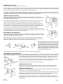
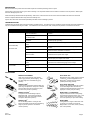
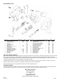
INSTRUCTION MANUAL
Magna-Spot® Studwelder
Models JO1000, JO1500, JO2000
*
WARNING:
Read and understand all instructions before attempting to operate tool.
Failure to follow instructions may result in electric shock, fire and/or serious personal injury.
IMPORTANT SAFETY INSTRUCTIONS
*
To reduce the risk of serious injury and/or property
damage, observe all warnings and instructions while
operating the welder. Keep work area clean and well lit.
Maintain tool in top condition and obtain service from
manufacturer if tool malfunctions. Use only accessories
and replacement parts that are provided by the
manufacturer.
8
This welder must be connected to a properly
grounded outlet installed in accordance with all local
codes and ordinances. Never remove the grounding
prong or modify the plug in any way. Do not use adapter
plugs. Consult an electrician if you are in any doubt as to
whether the plug is properly grounded. Avoid bodily
contact with grounded surfaces.
+
To reduce the risk of electrical shock: Do not expose
welder to rain or wet conditions. Water entering tool will
increase the risk of electrical shock. Unplug welder when
not in use. Do not operate welder with any portion of the
housing removed. Disconnect welder from power supply
before servicing any part of the welder. Failure to follow
these instructions will increase the risk of electrical shock.
!
Do not operate tool in explosive atmospheres, such
as in the presence of flammable liquids, gases or dust.
Welders create sparks which may ignite dust or fumes.
Use in well ventilated areas only. Welders generate heat
which can ignite surrounding materials causing fires. Do
not use welder on body panels containing insulating
material which may be ignited by the heat.
+
Do not abuse power cord. Never use the power cord for
carrying, pulling or unplugging the welder. Keep power
cord away from heat, sharp edges and moving parts.
Replace power cord immediately if it becomes damaged.
Damaged cords increase the risk of electrical shock.
O
A
Always wear proper personal protection when
operating welder. Proper eye protection is required to
reduce the risk of eye injury from sparks and molten
metal. Adequate gloves and clothing are required to
reduce the risk of burns. Allow parts to cool before
handling.
SAVE THESE INSTRUCTIONS
IF YOU HAVE ANY QUESTIONS ABOUT THE OPERATION OF PRODUCT CALL TOLL FREE
800-227-2822
8:00 am to 5:00 pm - Pacific Time - Monday through Friday
PREPARING TOOL FOR USE
Read and understand all warnings and instructions prior to use.
For 120V operation in the US and Canada, a three prong plug is provided. For units rated at 240V, a field supplied, approved plug must be installed by
the user. Consult an electrician for the proper connector. Supply circuit receptacle, conductors, fuses and circuit breakers must be capable of handling
a 15 ampere load. Welder should be the only device connected to the circuit being used.
An adequate power supply is required for proper welding operation. The welder is provided with a 9 foot power cord which should be suitable for most
work stations. If an extension cord is required, it must be a three wire grounded cord with a minimum of 12 AWG conductors. Cord must not exceed 10
feet in length. Reduced welding capacity will result from the use of undersized or long extension cords.
GENERAL WELDING PROCEDURE
Select proper electrode tip for work to be performed. Insert electrode tip into welder, tapered end first, and
rotate slightly for a tight fit. (Fig. 1) Use opposite procedure to remove electrode tip. A box end wrench can be
used to twist electrode slightly to loosen.
Proper welding requires that the surface to be welded be clean, bare metal free of paint, primer, oil and dust.
Grind area to be welded to expose bright metal approximately one inch all around area to be welded.
Insert pin or rivet to be welded in electrode tip and place tip of electrode against exposed metal. Press until
outer electrode tube is in full contact with bare metal. Hold welder in this position and depress trigger for onehalf to one second. A proper weld is achieved when the heat affected area around the weld is approximately
1/4” in diameter. To prevent sparking, do not pull electrode tube back until trigger is released.
Figure 1
Do not hold trigger for more than one second as burn through may result. Operating the welder beyond its duty
cycle (one second on, 60 times per hour) will result in tripping of the circuit breaker. Allow welder to cool for one
minute before resetting the circuit breaker and resuming welding.
DENT REMOVAL WITH MAGNA-PINS®
®
Prepare metal at damaged area per above instructions. Insert Magna-Pin electrode tip into welder followed by
®
a Magna-Pin . (Fig. 2) Use 2.0mm pins for dent removal on lightweight body panels and 2.5mm pins for posts
and heavier panels. Weld pin as instructed above.
®
Magna Slide Hammer, T-Puller or Clamp may be used for dent repair depending on extent of damage and
panel thickness. (Fig. 3) Grip pins 1/2 inch from surface and apply steady pressure while working dent with
appropriate body hammer. Slide hammer action may be used for more extreme pulling.
Figure 2
Rotate head of Slide Hammer clockwise 1/4 turn to grip
pins, opposite direction to release. Rotate knurled wheel
of T-Puller back to lock pin for pulling. To release, push
puller forward while rotating wheel forward. Electrode
Extension and Adapter Tube may be used for welding in
difficult areas and to place pins close together for more
effective pulling with clamps. Rotate wing-nut on Magna®
Clamp clockwise to tighten. Strike end of hook with
hammer to release then loosen nut.
Figure 3
Use side-cutting wire cutters to remove studs after repair. Rock pin and twist slightly until it breaks off.
DENT REMOVAL WITH MAGNA-WIRE®
Prepare metal at damaged area per above instructions. Slide adapter over outer electrode tube. Tap into place as required to seat firmly. Insert Magna®
Wire electrode tip into welder. Use 16 Ga. wire for dent removal on lightweight body panels and 12 Ga. wire on heaver panels. Place wire between
body panel and tip of electrode as shown. (Fig. 4) Weld as instructed above. Weld wire at each contact
point or at alternating points as required. Take care not to burn through wire by applying too much heat.
®
Use Magna-Claw or other device to work crease out, starting at one end and working to the other. Magna®
Claw fingers provide self-leveling action by pulling deeper recesses first until dent is removed.
Use pliers to remove wire by rocking back and forth at weld points.
TRIM RIVET INSTALLATION
Figure 4
Prepare metal at area of rivet installation per above instructions. Insert trim rivet electrode tip into welder
followed by trim rivet. (Fig. 5) Rivet will be held by magnet in electrode. Weld as instructed above.
SHRINKING STRESSED METAL
Shrinking electrode tip can be used to raise low areas or shrink high spots. Prepare area around damage as
instructed above. Insert shrinking electrode tip into welder.
To remove low spots, place rounded tip of electrode at several points around spot and depress trigger for onehalf second two or three times. Be sure outer electrode tube is in contact with bare metal while doing this.
Immediately apply cold blocking or wet cloth to area to shrink it back to its original shape.
Figure 5
33115
Rev 10/08
To remove high spots and repair pin weld points, place rounded tip of electrode directly on high spot and
depress trigger for one-half second. Repeat as needed. A gentle hammer on heated metal may be used for
heavier damage.
Page 2
MAINTENANCE
Disconnect welder from power source and allow all parts to cool before performing service or repair.
Inspect power cord at each use for signs of wear or damage. Do not operate welder if wear or breaks in insulation or wire are present. Obtain repair
service for damaged power cord.
Clean electrode tips and electrode tube periodically. Steel wool or a fine wire brush can be used to remove oxidation and carbon from electrode
surfaces. Replace electrodes when they become excessively worn.
Inspect case, switch and circuit breaker periodically and obtain service if damage is present.
TROUBLESHOOTING
Troubleshooting of internal parts must be performed by qualified persons. The following chart is intended to provide remedies for simple problems that
may be encountered when using the welder. For malfunctions not covered by this chart, contact place of purchase or manufacturer for service.
Trouble
Possible Cause
Remedy
No Output
Open Line Fuse or Tripped
Line Circuit Breaker
Check for power at outlet. Replace fuse or reset circuit
breaker.
Tripped Circuit Breaker
On Welder Case
Wait for welder to cool. Reset circuit breaker on case.
Weld Circuit Not
Complete
Ensure that electrode tube is in full contact with clean base
metal for proper grounding.
Low Output
Weld Time Too
Short
Increase weld time to achieve proper weld.
Poor Weld Quality
Work Surface Not
Clean
Remove all paint, rust, dust and oil to obtain a dry bright
surface.
Base Metal Too Thick
Welder is designed for use on sheet steel of the type and
thickness used in automobile construction.
Electrode Tip or Electrode
Tube not Clean
Remove all carbon and oxidation from electrode tip and
electrode tube to expose clean copper.
Pins Corroded / Not Clean
Clean pins to remove contaminants and let dry. Sand a small
area on tip of pin to expose clean metal.
Improperly Sized Extension
Cord
Do not use an extension cord if at all possible. Check
instructions for recommended gauge and cord length.
Weld Time Too
Long
Decrease weld time to prevent burn through.
Base Metal Too Thin.
Check instructions for proper material and thickness.
Pins Won’t Hold
Burn Through at
Point of Weld
ACCESSORIES
®
MAGNA-SLIDE HAMMER
Heavy duty construction with quick release
chuck to grip pins firmly without slipping. Cast
iron slide weight and comfortable vinyl grip.
(J20003)
®
MAGNA-CLAMP
Constructed of heat-treated, hardened steel with
quick wing-nut adjustment. Clamps on to multiple
pins and makes quick work of pulling on posts
and other heavy sections. (J20016)
®
MAGNA T-PULLER
A compact tool for small damage repair on
lightweight metal. Convenient thumb wheel
locking and a firm grip. Hand pulling reduces
over-pull for detail work. (J20017)
®
MAGNA-CLAW
®.
For use with Magna-Wire Five finger claw
features all welded construction and self-leveling
design to pull low spots first. Excellent for
creases. (J20037)
33115
Rev 10/08
ELECTRODE TIPS
Machined from high quality copper for highest
conductivity. Covers all applications from
®
Magna-Pins (J20007) and Trim Rivets
(J20009) to Shrinking (J20006).
ELECTRODE ADAPTERS
Adapter Tube (J20022) extends tip of welder
®
for use with Magna-Wire Electrode Tip
(J20020) or Electrode Extension (J20011) for
tight spots or side by side pin welding.
®
MAGNA-PINS and TRIM RIVETS
Copper coated steel is soft for easy flexing
and grinding but delivers a 500 lb. pull. In two
sizes; 2.0 mm (J20014) 2.5 mm (J20015).
Trim rivets (J20012) for repair of all molding.
®
MAGNA-WIRE
Corrugated wire is copper coated steel. Use
to pull out long creases evenly with the
®
Magna-Claw . In two sizes; 16 Ga. (J20024)
and 12 Ga. (J20025)
Page 3
REPLACEMENT PARTS
ITEM
1
2
3
4
5
6
7
8
9
10
11
12
13
14
15
16
DESCRIPTION
INSULATOR SLEEVE
HEX NUT 5/16-18 BRASS
FLAT WASHER, SAE 5/16 BRASS
HEX NUT 1/4-20
LOCK WASHER, SPLIT 1/4
LOCK WASHER, SPLIT 5/16
BRAIDED STRAP
MACHINE SCREW, SLOTTED 10-32 X 1-3/4
CASE, RIGHT-HAND
FLAT WASHER, SAE 1/4
CAP SCREW, HEX 1/4-20 X 3/4 GR5
TRANSFORMER 1000/1500 SERIES 120V
TRANSFORMER 1000/1500 SERIES 240V
TRANSFORMER 2000 SERIES 120V
INSULATOR, TRANSFORMER
HEX NUT 10-32
CASE, LEFT-HAND
POWER CORD
QTY
1
2
2
2
2
1
1
6
1
4
1
1
1
1
1
8
1
1
PART NO.
JP1030
JP1020
JP1021
JP1029
JP1005
JP10081
JP10083
JP10082
JP1028
JP1006
JP1000
ORDER NO.
ITEM
52410
44025
44270
44015
44345
44350
52205
44170
CALL
44260
44072
52430
52433
52440
52405
44010
CALL
52010
17
18
19
20
21
22
23
24
25
26
27
28
29
30
31
32
DESCRIPTION
TRIGGER SWITCH
BOOT, TRIGGER SWITCH
MACHINE SCREW, SLOTTED 10/32 X 7/8
CIRCUIT BREAKER 1000/1500 SERIES 120V
CIRCUIT BREAKER 1000/1500 SERIES 240V
CIRCUIT BREAKER 2000 SERIES 120V
INSULATOR, ELECTRODE TUBE
CAP SCREW, HEX 1/4-20 X 5/8 GR5
RETAINER, MPS SYSTEM
WASHER, MPS SYSTEM
SLIDING ELECTRODE (INCLUDES RETAINER)
SPRING, SLIDING ELECTRODE
ELECTRODE TUBE ASSEMBLY
WIRE ASSEMBLY, BARE
WIRE ASSEMBLY, FORK
TERMINAL, CLOSED END
MAGNET, MPS CASE
INSULATOR, MAGNET
QTY
1
1
2
1
1
1
1
1
1
1
1
1
1
1
1
2
1
1
PART NO.
JP1010
JP1039
JP1007
JP10091
JP10093
JP10092
JP1013
JP1017
JP1018
JP1011
JP1015
JP1016
JP1041
JP1040
JP1036
JP1019
JP1031
ORDER NO.
52310
52305
44165
52356
52351
52360
22282
44070
22550
44285
11122
61280
12205
52210
52215
52055
95382
52407
FIVE YEAR LIMITED WARRANTY
Motor Guard Corporation assumes the responsibility of providing products that are free from defects in workmanship and material. Should a product fail
due to a defect in workmanship or material, Motor Guard Corporation will repair or, at its option, replace the product without charge, other than the
transportation charges, provided that the product is returned to the factory, transportation prepaid, within Five (5) Years of the date of purchase. Please
contact Motor Guard Corporation for return authorization and shipping instructions.
This limited warranty does not cover normal wear and tear or damage to the product due to neglect, misuse or accident, nor does it cover any loss,
damage or expense, either direct, indirect or consequential, arising from the non-function of this product.
See enclosed warranty card for coverage details and instructions for obtaining warranty service.
OBTAINING SERVICE
To assure product safety and reliability, repairs, maintenance and adjustments should be performed by authorized service centers using replacement
parts provided by the manufacturer. To obtain service, return tool to place of purchase or contact the manufacturer directly:
Motor Guard Corporation
580 Carnegie Street
Manteca, CA 95337
U.S.A.
Toll Free: (800) 227-2822
[email protected]
Hours: Mon-Fri 8:00 am to 5:00 pm PST
33115
Rev 10/08
Page 4