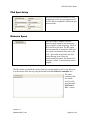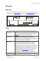
1
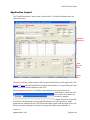
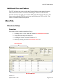
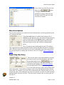
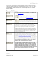
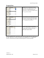
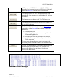
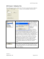
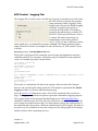
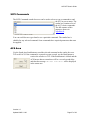
ACS VFP User’s Guide
Agile Coherent Synthesizer
Virtual Front Panel User’s Guide
Innovative
Technology
Version 1.0
Updated 2005-11-06
Page 1 of 39
ACS VFP User’s Guide
TABLE OF CONTENTS
OVERVIEW
4
WHAT IS THE VIRTUAL FRONT PANEL?
HUMAN INTERFACE NOTES
APPLICATION LAYOUT
4
4
5
INSTALLATION
7
BASIC INSTALLATION
ADDITIONAL FILES AND FOLDERS
7
8
MAIN TAB
8
WAVEFORM SETUP
8
OVERVIEW .......................................................................................................................... 8
FILE MANIPULATION .......................................................................................................... 9
WAVEFORM OPTIONS ...................................................................................................... 11
EQUAL STEP SIZE ENTRY ................................................................................................. 11
WAVEFORM DESCRIPTION ................................................................................................ 12
LOAD FROM AND SEND TO ACS ...................................................................................... 12
WAVEFORM GRID AREA ................................................................................................... 12
Overview.............................................................................................................. 12
Waveform Grid Columns..................................................................................... 13
Table Buttons....................................................................................................... 14
Dragging Rows.................................................................................................... 15
ACS CONTROL
16
ACS SHARED CONTROL AREA ......................................................................................... 16
ACS CONTROL - CONTROL TAB ....................................................................................... 17
Overview.............................................................................................................. 17
Trigger Source Stepping...................................................................................... 18
Manual Stepping ................................................................................................. 20
ACS CONTROL - TEST TAB .............................................................................................. 21
Test Tab Controls ................................................................................................ 21
ACS CONTROL - CALIBRATION TAB ................................................................................ 23
ACS CONTROL - LOGGING TAB ....................................................................................... 25
TOOLS TAB
SCPI COMMANDS
ACS AREA
POWER METER
DIAGNOSTIC MESSAGES
TOOLS STATUS MESSAGE AREA AND BUTTONS
26
27
27
28
29
30
Version 1.0
Updated 2005-11-06
Page 2 of 39
ACS VFP User’s Guide
SPURS TAB
PSA SETUP
PSA DIRECT COMMANDS
SPUR SOURCE
PSA SPUR SETUP
MEASURE SPURS
STATUS BAR
OVERVIEW
PANES
SPECIAL CONDITION STATUS BARS
31
32
32
32
33
33
34
34
34
35
DEFAULT SETTINGS
36
APPENDIX A
37
USING WAVEFORMS CREATED IN EXTERNAL PROGRAMS ................................................ 37
APPENDIX B
38
BASIC SCPI COMMANDS .................................................................................................. 38
Version 1.0
Updated 2005-11-06
Page 3 of 39
ACS VFP User’s Guide
Overview
What is the Virtual Front Panel?
The VFP is a graphical user interface that runs on a Window’s compatible personal
computer for setting up and controlling Innovative Technology’s Agile Coherent
Synthesizer. While there are a few things that the software can do without being attached
to an ACS the majority of the functionality requires that an ACS be connected via
Ethernet. The VFP software contains many controls to make creating waveforms easy. It
communicates with the ACS via the SCPI command set of the instrument. The VFP
software also provides means for monitoring and logging these commands for audit and
learning purposes. Several functions of the VFP go beyond the standard purpose of a
virtual front panel including, measuring power and spurs. The VFP was designed and
testing under Windows XP and Windows 2000. The software may work under earlier
versions of Windows but it has not been verified to do so.
Human Interface Notes
Unlike most PC based applications the VFP software has only a File and Help menu. All
the functions of the software are immediately available directly from the visual controls
on the screen. An effort has been made to minimize hidden features but there are a few
places where double-clicking or dragging will save you time and these features are
documented in this manual.
Version 1.0
Updated 2005-11-06
Page 4 of 39
ACS VFP User’s Guide
Application Layout
The Virtual Front Panel’s main layout is shown below. The Major functional areas are
called out in Red.
Main Tabs
ACS Progress Area
Waveform
Setup Area
ACS
Control
Area
Status
Bar
The Main Tabs are used to switch to other major functional areas of the application. The
Tools and Spurs tabs add capabilities beyond the functionality of a virtual front panel and
aren’t needed for normal operation of the ACS.
The ACS Progress Area will display a thermometer style progress bar when
commands are sent to the ACS
that can take more than a few
seconds to complete.
Loading waveforms (especially
waveforms with thousands of rows), and calibrating are two such operations. Some
operations are controlled by the VFP (like downloading a table) and the progress bar will
fill only one time during the execution of the operation. Other operations take in
Version 1.0
Updated 2005-11-06
Page 5 of 39
ACS VFP User’s Guide
indeterminate amount of time (like calibrating the ACS). In those cases the progress bar
may fill multiple times while the operation is underway.
The Waveform Setup Area provides multiple ways to configure a waveform and two
buttons that communicate with the ACS.
The ACS Control Area contains all the standard controls for manipulating the
operation of the ACS. This area can work with the waveform setup area when using the
manual stepping mode.
Version 1.0
Updated 2005-11-06
Page 6 of 39
ACS VFP User’s Guide
Installation
Basic Installation
There is no special installer required for the application. The application consists of the
executable file (ACS_VFP.exe) and the ACS.mdb file Those are the only files that are
required. These files can be put in the same folder anywhere on the computer’s hard
drive. If you have multiple ACS instruments you want to control you can create multiple
instances of this folder. Make sure each folder contains both the executable and the
ACS.mdb file. The ACS.mdb file is typically unique for each synthesizer.
The ACS.mdb file is an Access database file that is read by the ACS at startup. Initially
the ACS only looks for the first record in the file to retrieve the TCP/IP address. Once
connected to an ACS the VFP reads the serial number from the ACS and then issues a
query to the ACS.mdb file for that ACS unit. This allows the VFP to remember:
the TCP/IP for a particular synthesizer
the last waveform setup parameters
all the factory default configuration information.
The address of the ACS can be set from the Front Panel (please see the User Technical
Guide). The Factory Default is 192.168.0.208. If you need to use a different address use
the instrument’s Front Panel to change the address and cycle the power to the instrument.
Then use the VFP and enter the new TCP/IP address and hit connect (see the ACS Shared
Control Area for details).
The new TCP/IP address is
automatically written in
the ACS.mdb file. The
software displays the
connection dialog when
attempting to communicate
with the ACS. The ACS always uses TCP port 23 for communication.
If a connection can’t be established an error dialog will be displayed. The application can
still launch and it can be used
to configure and save
waveforms to disk files but you
won’t be able to communicate
with the instrument until a valid
connection is established. See
the Reconnect button in the
ACS Control section for more
information. Also if an ACS can’t be detected you will also receive an error that the
matching record for the Synthesizer’s serial number can’t be found in the ACS.mdb file.
It is safe to ignore these errors.
Version 1.0
Updated 2005-11-06
Page 7 of 39
ACS VFP User’s Guide
Additional Files and Folders
The VFP software can create several other files and folders during normal operation.
None of these files needs to exist before launching the software for the first time.
The VFP software can display several of the PDF guides that ship with the ACS. This
feature requires that the PDF files exist in the same folder as the VFP .exe file. This
feature is available under the Help menu.
Main Tab
Waveform Setup
Overview
Waveforms can be created in a number of ways:
1. Loading text or csv files from disk from the File Manipulation area.
2. Using the Equal Step Size Entry area
3. Loading the current waveform from the ACS
4. Manually entering data in the Waveform Grid area.
File Manipulation
Waveform Grid Area
Version 1.0
Updated 2005-11-06
Page 8 of 39
ACS VFP User’s Guide
Figure 2. Waveform Setup Detail
File Manipulation
This feature is primarily intended to load files that were previously saved using the VFP
software. Files from other applications may be used if the file format is compatible. This
option is discussed in more detail in Appendix A.
button in the file
You can load an already existing file by pressing the
manipulation area. This will launch a
standard open file dialog. Navigate to
the file you wish to load and click Open.
By default the dialog filters available file
to those with an extension of .txt. If the
file has an extension of .csv, use the
Files of type: popup at the bottom of the
dialog to select CSV Files.
After clicking on Open, the waveform grid area will be populated with the data from the
file and the name of the opened file will be shown in the current File Name
area:
The data file also contains a header that restores the settings for the following:
•
•
•
•
•
•
Dwell Units
Frequency Units
Preamble Row
Trigger Settings
Marker Settings
Waveform Description
Once a file has been opened the
button will
enable. Clicking this button will
save the current grid and settings
back to the same file that was last
loaded. Since this will overwrite
the existing file a warning dialog
is displayed:
Version 1.0
Updated 2005-11-06
Page 9 of 39
ACS VFP User’s Guide
Clicking the Yes button will save the file.
Version 1.0
Updated 2005-11-06
Page 10 of 39
ACS VFP User’s Guide
If you wish to save the file with a new
name use the
button.
Clicking this button will open a
standard save dialog. Enter the new
file name in the File name: area and
click the Save button.
Waveform Options
The Waveform Options area controls how data loads into the waveform grid and how the
ACS interprets the data.
If the Overwrite option is enabled, then loading a file or
building an equal step size entry will replace the data currently
in the waveform grid. If the Append option is enabled then
many files from disk can be concatenated with each other,
with equal step size entries and with any existing manual
entries.
The ACS supports many default units but the VFP software
only supports microseconds and milliseconds for dwell and MHz and GHz for frequency
entry. Set these options for the units you are most comfortable using. These units can be
set at any point prior to sending the waveform to the ACS with the Send To Synthesizer
button.
Equal Step Size Entry
This area provides a convenient method for entering
data that is equally spaced in frequency. Fill in the
button to
desired data and press the
fill in the waveform grid. The units of the data are
specified by the settings in the Waveform Options
area described earlier. This area also has a secondary
use. Each field in this area can be used to fill the table
with a fixed value. You do this by entering a value in the field and then double-clicking
on the field. For example, if you load a file of data that has the frequency data just as you
want it, but it has a 5 ms dwell and you want a 10 ms dwell, you enter 10 in the dwell box
and then double-click the dwell box. The entire dwell column in the waveform grid will
fill with 10.
Version 1.0
Updated 2005-11-06
Page 11 of 39
ACS VFP User’s Guide
Waveform Description
A text description of the current
waveform can be entered and sent to
the ACS. This description is loaded
when the Load from Synthesizer button is used. This value is also written out to the
waveform file when the waveform is saved to disk.
Load From and Send To ACS
This button will load the current waveform from the ACS into
the Grid. If the Overwrite radio button is selected in the
Waveform Options it will replace the existing date, otherwise
it will be appended to the end of the existing table. This button
also loads the waveform description from the synthesizer into
the waveform description area.
This button will send the current table in the Waveform Grid
Area to the ACS. The units in the Waveform Options area will
be used when this button is pressed. If the units are changed
this button needs to be pressed again to resend the waveform
with the changed units. This button also aborts any current run
and mutes the RF power. It also checks for any errors and
displays them in a dialog if found.
When any change is made to the waveform table this button
will be emphasized as shown at left in the bottom icon.
Entering a value in the grid area appears to the software as a
change, even if it is the same as the old value in the cell, and
causes the button to be emphasized.
Waveform Grid Area
Overview
Version 1.0
Updated 2005-11-06
Page 12 of 39
ACS VFP User’s Guide
The waveform grid area can be directly manipulated. Click in a cell and start typing
values. You can move from cell to cell with the mouse, tab key, or arrow keys. The up
and down arrows will move between rows. The left and right arrow keys will move
between columns.
Waveform Grid Columns
The first column holds the Row number. This column is also
used for dragging rows.
The second column holds the frequency The units
for this column are determined by the frequency
radio buttons in the Waveform Options Area.
The third column holds the frequency dwell time.
The units for this column are determined by the
dwell radio buttons in the Waveform Options Area.
The fourth column holds the attenuation offset in dB from the
calibrated value. A positive number will add additional
attenuation. A negative number will increase the gain. The
actual amount of attenuation available varies for each
frequency depending on how much attenuation was used to
calibrate that particular frequency. In general the system has
45 dB of attenuation available. However, it is best to limit
values in this column to ±10.
The fifth column controls the values for marker 1 and marker 2
when the markers are put under Table control. This is done
using the Synthesizer Control Area’s Marker settings. There
are only three valid values for this column 0, 1, and 2. A value
of 0 leaves both markers off. A value of 1 turns on marker 1
for the duration of the segment. A value of 2 turns on marker 2
for the duration of the segment. A value of 3 turns on both
markers 1 and 2 for the duration of the segment.
The final column “Calculated Synth. Frequency” is a nonenterable, calculated value. The ACS generates frequencies
based on a 400 MHz clock divided by a 32 bit counter. This
makes the minimum frequency change .093132 Hz. Not all
frequencies are directly synthesizable as entered. This column
shows the exact frequency that the ACS will generate.
Version 1.0
Updated 2005-11-06
Page 13 of 39
ACS VFP User’s Guide
Table Buttons
Rows can be inserted into the grid using this button. The row
will be added directly above the currently selected row. If the
shift key is held down the row will be added directly below the
currently selected row. A row can be selected by clicking or
double-clicking in a cell.
The current row can be deleted by clicking this button.
This button will delete any row where the frequency column
doesn’t contain any data.
This will do a fast delete of all the rows in the waveform grid.
This button affects the entire waveform grid. For each entered
frequency it finds the closest frequency that the ACS can
generate to the exact HZ with no portion below 1 Hz. For
example if you enter 8002.2 MHz the ACS will generate
8001.19999998808 MHz. The nearest frequency to the exact
HZ will be 8002.34375. This feature is useful when using the
ACS with other test equipment that doesn’t have resolution
below 1 Hz and both instruments have to be on the same
frequency.
The current row will be set as the preamble when this button is
clicked. The Row number will be replaced by a “P” to indicate
the preamble has been set. In the example below, row 3 has
been set as the preamble.
Clicking this button a second time will clear the preamble row.
In some modes the ACS will execute the preamble portion of
the table once, and then loop on the remaining “main” portion.
Version 1.0
Updated 2005-11-06
Page 14 of 39
ACS VFP User’s Guide
Dragging Rows
Dragging a row is initiated by clicking
down in the first column of the row you
want to move and keeping the mouse
button down. A dark line will appear above
the row you have clicked.
Drag the dark line up or down and the row
you selected will be placed directly under
the dark line. In this example, the original
row 2 is going to become Row 1.
When the mouse button is released the
rows are reordered. Row 2 has become row
1 and the order of Frequencies is now
8000, 8020, and then 8010.
The row dragging feature is particularly useful when you want to add rows at the end of
the table. Since rows are always inserted before the highlighted row, you highlight the
last row, click the insert row button, and then drag the row to the last position.
Version 1.0
Updated 2005-11-06
Page 15 of 39
ACS VFP User’s Guide
ACS Control
The ACS Control area contains multiple tabs with options that send various SCPI
commands to the ACS.
ACS Shared Control Area
This area on the far right of the ACS Control area is
available from all the ACS Control area tabs. When the RF
OFF button is depressed and red the power to the ACS is
muted. When the RF ON button is depressed and green the
power is un-muted.
The ACS TCP/IP Address area can be used to change the
default address of the ACS. Type in a new address and
click the reconnect button.
The
button also can be used if the ACS
was not powered on when the VFP software was first
started or if for any reason TCP communication with the
ACS is interrupted. When pressing the Reconnect button
the VFP software will attempt to make a connection for
approximately 30 seconds. The VFP software is
unresponsive during this time. If the connection is not
made the TCP connection error dialog show under Basic
Installation will appear. The VFP will also re-query the
ACS.mdb file to retrieve information for the ACS based on
the serial number read from the ACS unit. The Test Tab
status area can be used to tell if a connection is made (see
below).
The
button can be used to stop waiting for
Version 1.0
Updated 2005-11-06
Page 16 of 39
ACS VFP User’s Guide
an operation to complete on the synthesizer. Some
operations take an indeterminate amount of time and the
VFP waits for a response to the OPC? SCPI command.
While waiting it will continually update the status bar.
Under certain conditions (e.g. if the TCP connection is
lost) you may want to recover from this wait.
The
button will quit the application. You
can also quit using standard methods like:
•
clicking the
•
double clicking the
•
icon’s menu as shown at the
using the using
left, or by hitting Alt+F4
•
Using the File menu and selecting Exit
icon
icon
ACS Control - Control Tab
Overview
The Control Tab has the standard commands for controlling the ACS. The Trigger and
Marker settings aren’t sent to the ACS until the Run button is hit.
Version 1.0
Updated 2005-11-06
Page 17 of 39
ACS VFP User’s Guide
Trigger Source Stepping
The Trigger Source Stepping area contains the controls for the Trigger, Marker and Run
commands. The settings in this area aren’t sent to the ACS until the Run button is
clicked.
Trigger
The items in the Trigger area are interrelated. The Source
popup selection can enable and disable some of the other
areas.
The behavior of each trigger source is discussed below.
Free Run
Free Run will ignore both external triggers, loop counts and
the continuous loop setting. When the ACS is set to Free Run
it arms and immediately issues a trigger to start looping
through the waveform.
Internal
Internal triggering honors the loop count and continuous loop
settings. External triggers are not used so the Enable area
remains dimmed. When the run button is hit the ACS operates
similar to the Free Run mode because the VFP software
automatically issues a software trigger (AKA Bus trigger), i.e.
SCPI command *TRG.
External
In External mode all the Trigger areas are
enabled and honored. This is the only
mode where the Enable popup is activated.
If Both is selected then both Segment and
Sequence triggering is controlled from the
external trigger ports on the ACS.
If Sequence is selected then the ACS waits for an external
Sequence trigger to arm and the waveform dwell time controls
the segment trigger. Any external segment triggers that are
received are ignored. Any subsequent sequence triggers will
cause the waveform to jump to the first row after the preamble.
If Segment is used then the ACS self arms. Any input on the
Sequence trigger is ignored. Each external segment trigger will
Version 1.0
Updated 2005-11-06
Page 18 of 39
ACS VFP User’s Guide
move the ACS to the next row in the waveform.
Fiber
All other trigger settings are deactivated and ignored. The fiber
interface controls all aspects of addressing the waveform.
Parallel
All other trigger settings are deactivated and ignored. The
parallel interface controls all aspects of addressing the
waveform.
Markers
The markers are configured using the two popups in the Markers area.
When Marker 1 is not “None” it can be configured to be
controlled from the Waveform Table or it can be linked to the
Sequence trigger. When set to Sequence, the marker will
display every time a sequence trigger is detected. The pulse
width will be fixed.
When Marker 2 is not off it can be configured to be controlled
from the Waveform Table or it can be linked to the Segment
trigger. When set to Segment, the marker will display every
time a segment trigger is detected. The pulse width will be
fixed.
Run/Abort
The Run button performs the following actions
•
Aborts any current run
•
Sends the settings for the Trigger area
•
Sends the settings for the Marker area
•
Forces the cal state to On.
•
Turns on the RF Output power
The arming and trigger commands are performed last.
The Abort buttons sends the Abort command to the ACS and
turns off the RF Output power.
Version 1.0
Updated 2005-11-06
Page 19 of 39
ACS VFP User’s Guide
Manual Stepping
The manual stepping mode commands are sent to the ACS
immediately. The manual stepping mode is independent of the
Run command and the trigger mode. In effect, it overrides the
Trigger Source command from the Trigger Source Stepping
area. The manual stepping mode is technically a diagnostic
mode and the concepts of sequence, segment and preamble do
not apply. The Current Step field corresponds to the row in the
waveform grid. To go to any specific row enter a row number
and hit the tab key. The Next and Previous step buttons also
increment and decrement the current row in the waveform
table. As a visual reminder the waveform grid rows are
scrolled so that the top row in the
grid is the current row. Note in
the example how Row 2 is at the
top of the table. If there aren’t
enough rows in the table for the
scroll bars to appear you can scroll
back to row 0 by clicking on an
enterable cell and scrolling with the arrow keys or the mouse
wheel.
If the wraparound checkbox is checked then clicking Next on
the last row will take you the first row and clicking Previous
while on the first row will take you to the last row.
Version 1.0
Updated 2005-11-06
Page 20 of 39
ACS VFP User’s Guide
ACS Control - Test Tab
The VFP at times automatically requests information from the output buffer of the ACS
and writes that data in the Test Tab’s status area. One of these times is when a connection
is first made after initially starting the program. The welcome message “Innovative
Technology Agile Coherent Synthesizer” is retrieved from the output buffer and the
software sends the standard IEEE 488 *IDN? SCPI command and reads the results. This
result is shown below and includes the same welcome string, the TCP/IP-Netmask, Serial
Number, firmware version and FPGA code version number.
Test Tab
Status
Area
Test
Tab
Controls
Test Tab Controls
Enabling this checkbox will cause the VFP to write the SCPI
commands being sent to the ACS to also be written to the Test
Tab Status Area. Example output after hitting the Send To
ACS button when the waveform grid had five rows is shown
below:
Enabling this checkbox starts a timer that fires once
approximately every three seconds requesting the status byte
Version 1.0
Updated 2005-11-06
Page 21 of 39
ACS VFP User’s Guide
(SCPI command “*STB?”) from the ACS. The VFP then
parses the bits from that byte per the SCPI User’s Guide and
updates the Status Bar with the retrieved information.
This button will query the ACS for any information in the
output buffer. If no messages are available then “O, No Error”
is returned.
This button erases all the text in the Test Tab Status area.
This button will save the current status area text content to a
file specified by the user.
The Measure Power button is dimmed until a Power Meter is
connected to via the Tools tab. Once enabled, pressing this
button will:
•
•
•
•
clear the status area
cycle through the rows in the waveform grid from the
first row through the last
read the power from the power meter for each row
write the frequency and measured power into the Test
Tab’s status area.
The user must make sure that the current waveform in the
waveform grid has been sent to the ACS for accurate results.
The Self Test button runs the heartbeat built-in-test followed
by the frequency dependent built-in-test. Detailed error
messages are displayed for any failures. Sample error
messages are shown below.
Sample Bit Failure Messages
Version 1.0
Updated 2005-11-06
Page 22 of 39
ACS VFP User’s Guide
ACS Control - Calibration Tab
The Calibration tab is used to calibrate the ACS either by running the built-in calibration
routines or by downloading a calibration table.
The type popup allows either a single stage of the calibration or
the entire calibration
sequence to be run.
The user is prompted
to attach a load before
running any
calibration.
There is only one
prompt so if “All” is
chosen terminators should be attached to both the 250-1050
MHz (Low) and 850-1800MHz (High) bands. The UHF Up and
Down calibrations are fairly quick. The Low and High band
calibrations are done every MHz. The entire calibration process
can take over 15 minutes. Once the frequency calibration is
finished the data is stored internally on EEProm. Writing the
High band table into EEProm can take a couple of minutes.
This is pointed out because if you use external devices to
monitor frequency activity you will notice that the frequency
activity stops but calibration won’t finish for a couple of
minutes.
After selecting “All” or a stage from the Type popup click this
button to start the calibration. The calibration process replaces
the calibration table in the ACS’s memory and the copy stored
in the ACS’s EEProm.
Version 1.0
Updated 2005-11-06
Page 23 of 39
ACS VFP User’s Guide
If a table has
been
previously
loaded from
the ACS and
stored in a
text file
using the
VFP you can
use this
button to
send that
table back to
the ACS. Clicking this button will display a standard File Open
dialog box asking for the user to locate a valid calibration table
to send to the ACS.This will replace both the copy of the
calibration table in memory and the version stored in the
EEProm. Sending an invalid file will leave the ACS in an
uncalibrated state.
Use this button
to load the
current
calibration data
from the ACS
and save it into
a text file on
the hard disk.
The button will
display a
standard File
Save dialog
box.
Navigate to the folder where you want to save the file. Provide
a file name and extension and hit Save. The “Save as type:”
popup can be used to see existing .txt or .csv files on your hard
disk. You can save the file with either extension.
The Restore Factory Defaults button will load all the factory
default data from the ACS.mdb file into the synthesizer’s
memory and EEProm, restoring it to the same calibration and
setup state that existed when it left the factory.
Version 1.0
Updated 2005-11-06
Page 24 of 39
ACS VFP User’s Guide
ACS Control - Logging Tab
The Logging Tab is used to create a text file log of various events that occur while using
the VFP software. Each time the program
starts (assuming Enable Logging is on by
default) and every time the Enable Logging
checkbox is toggled a new log file is
created in the Logs folder. This folder is
located in the same directory with the VFP
EXE file. If the Logs folder doesn’t exist it
is created. File names for the logs are
automatically created with a prefix of
“ACS_VFP_Log” and a suffix that is based
on the month, day, year and millisecond since midnight. This format guarantees that a
unique filename is created. An example file name for January 10, 2005 around 3:30 pm
would be:
ACS_VFP_Log_1.10.2005.55431735.txt
The log file records most SCPI commands, error messages and significant events like
calibration and Self Test execution. A date/time stamp is included for most significant
events. An example log extract is shown below:
12/22/2004 4:32:23 PM
BIT: Failure
12/22/2004 4:32:24 PM
Self test initiated.
*TST?
SYSTem:ERRor:ALL?
1
BIT - Module: REFERENCE, Signal: PLXOALRM Out of range. Measured = 0.00;
lower limit = 1.50
OUTPUT OFF
12/22/2004 4:32:28 PM
BIT: Failure
The log file is a standard text file that can be opened with a text editor like Notepad.
However, the current log file being used by the VFP cannot be opened until the Enable
Logging checkbox is cleared or until the program quits.
Since the Send To ACS button can create a lot of SCPI commands if the waveform is
large. The logging area includes an option to ignore this command for logging purposes.
The Logging feature will monitor the heartbeat built-in test if the Read Status Byte
checkbox is enabled on the Test Tab. Since the VFP has no way of knowing whether the
user is using an external reference there is a radio button to specify the expected state. If
the monitored status byte reports a different condition then it will be logged. This built-in
test runs every five seconds so it can create a large text file if the program is left running
and the reference state is generating an error.
Version 1.0
Updated 2005-11-06
Page 25 of 39
ACS VFP User’s Guide
Tools Tab
The Tools tab contains diagnostic, serial port communication and troubleshooting aids.
Normal operation of the ACS will not require the use of this tab but it has several
powerful tools for the advanced user. The Tools Status Message Area is used by all
the tools on this tab to show results.
TOOLS STATUS MESSAGE AREA
Version 1.0
Updated 2005-11-06
Page 26 of 39
ACS VFP User’s Guide
SCPI Commands
The SCPI Commands combo box area can be used to select or type a command to send
the ACS or power meter. The
combo box contains a list of
the ACS’s basic commands.
The full contents of this
popup are shown in
Appendix B.
You can scroll down or type ahead to see a particular command. The combo box is
editable for any selected command. Some commands have required parameters that must
be supplied.
ACS Area
Use the Synth Area Send button to send the selected command on the combo box over
TCP to the ACS. If the command is expected to return a result, use the Read button to
retrieve the result over TCP. If the Read button is clicked and the
ACS has no data to return there will be a several second delay
and then the message “No data available” will be displayed
in the status area.
Version 1.0
Updated 2005-11-06
Page 27 of 39
ACS VFP User’s Guide
Power Meter
The Power Meter area is used to connect to an Agilent 4418B (or compatible) Power
Meter through a serial port on your computer. The VFP will configure the selected serial
port to work with the expected protocol of the Agilent. The Com pop up list can be used
to select the COM port to use from
COM1 through COM9. Once a
connection is made the Send and Read
buttons will enable and the label on the
Connect button will change to
Disconnect. The SCPI commands
combo box area is used to enter commands. Once connected, it is a
good idea to send the IEEE 488 command *IDN? Then click the Read
button to verify that the selected COM port is communicating with
the power meter. Also, once a valid connection is made the Measure
Power button on the Test tab will be enabled.
Version 1.0
Updated 2005-11-06
Page 28 of 39
ACS VFP User’s Guide
Diagnostic Messages
The ACS can use the serial port to send a wide range of diagnostic messages. The VFP
can act as a serial terminal to receive these messages for diagnostic purposes. Select a
COM port with the popup
and click the Connect
button. If a connection is
made the label on the
button will change to
Disconnect. The Message Level buttons are operational even if you don’t connect to a
COM port. This allows you to use an external program or even a separate computer to
monitor the serial port diagnostic messages.
All settings other than Off can affect the operation of the ACS as sending these messages
out over the serial port takes a measurable amount of time. Use the Off button to stay
connected but temporarily turn off all the diagnostic messages1. When any button other
than Off is clicked some messages are always sent regardless of the message level. The
Taciturn mode will turn on the lowest level of messages. Verbose turns on an extremely
chatty message mode that will definitely slow down most ACS operations. The TCP
mode sends some diagnostic information about TCP messages that are received. The
FPGA mode also sends diagnostic messages about which FPGA methods are getting
executed and the parameters for those messages. This entire area is meant as a
troubleshooting tool for use with technical support from the factory.
1
Even with the “Off” setting a few messages can still be sent over the serial port. These messages only
occur if a critical error has occurred in the synthesizer. In normal operation with the messages set to “Off”
no messages should be seen.
Version 1.0
Updated 2005-11-06
Page 29 of 39
ACS VFP User’s Guide
Tools Status Message Area and Buttons
The status area will display the results of communicating with either the ACS or the
power meter. The Clear Results button will delete all the text in the Tools Status area.
The Save To File… button will open a standard file dialog and allow you to save off the
contents of the status area to a text file.
Version 1.0
Updated 2005-11-06
Page 30 of 39
ACS VFP User’s Guide
Spurs Tab
The Spurs tab contains controls for measuring spurs on the ACS and communicating with
an Agilent E444xA PSA or compatible instrument.
Version 1.0
Updated 2005-11-06
Page 31 of 39
ACS VFP User’s Guide
PSA Setup
The VFP software must be told the address
of the PSA. Once the address is entered,
click the Connect button to establish the
TCP connection. The VFP always assumes
the PSA will use TCP Port 5025.
PSA Direct Commands
This combo box allows you to either select
from a handful of preentered commands or
type by hand any
command you wish.
Measuring spurs doesn’t
require the use of this area. However, once
a connection is established it is a good idea
to verify that connection by sending the
*IDN? command and reading the result.
Spur Source
The Spur Source area will preset some PSA
values in the PSA Spur Setup area for the
output section of the ACS that is being
evaluated for spurs. The Output Freq
button is the default selection and is used
when testing the spurious output of the
ACS at the front panel RF connectors. The
UHF Up, UHF Down, and S-Band options
should only be used if instructed to do so
by factory personnel.
Version 1.0
Updated 2005-11-06
Page 32 of 39
ACS VFP User’s Guide
PSA Spur Setup
The PSA Spur Setup area allows for easy
modification of the six main parameters of
the PSA that are modified for different spur
measurements.
Measure Spurs
Once the setup is complete click the
Measure Spurs button to start measuring
spurs using the current frequency values in
the Waveform Grid area. The RF output
will automatically be turned on. Make sure
the current waveform has been sent to the
ACS. The results are placed in the PSA
Status Message Area. Once the
measurement has started, this button will
change to “Abort” so measurement can be
stopped.
The PSA Status area holds the results of the spur measurements as well as any data sent
or read from the PSA directly using the buttons in the PSA Direct Commands area.
The entire
contents of this
area can be
saved to a file
using the Save
PSA Data to
File… button.
Version 1.0
Updated 2005-11-06
Page 33 of 39
ACS VFP User’s Guide
Status Bar
Overview
The Status bar is divided into five panes as shown below. These five areas are only
populated when the Read Status Byte checkbox on the ACS Control Test tab is enabled.
Panes
The five panes of status information are described in detail in the following table.
Built In Test
The Built in Test pane indicates either Normal or Failure. If a
failure is detected use the ACS Control Test tab and use the
Self Test button to get the details on the failure.
Calibration
The calibration pane will display either Normal or
Uncalibrated. An uncalibrated condition can indicate that
either the ACS has never been calibrated or that the calibration
table couldn’t be loaded from the EEProm.
Error Queue
The Error Queue pane will indicate that it is empty or has
messages waiting. The Error Queue is the only SCPI
communication buffer that the ACS has for transferring
detailed status messages to a host computer. Even standard
messages like responses to an *IDN? Query will post their
results in the Error Queue. For this reason, the error queue is
also referred to as the output buffer. You can retrieve error
messages using the Get Synth Msgs button on the ACS
Control Test Tab. This sends the SCPI command
SYST:ERR:ALL? SCPI, and then reads the output buffer.
External Reference
The External Reference pane indicates whether an external
Version 1.0
Updated 2005-11-06
Page 34 of 39
ACS VFP User’s Guide
reference is being used with ON. If the internal reference is
used it will show OFF.
Target ACS
The ACS pane will show the target TCP/IP address where the
ACS is expected. This is determined by the ACCAddr.txt file
located in the same folder as the VFP EXE file.
Resize Handle
The resize handle is a common window’s application control.
Click and drag to make the window smaller and larger. This is
particularly useful when there are long messages in the status
area, like when running the Self Test.
Special Condition Status Bars
When the program first starts and the Read Status Byte checkbox is cleared the status
bar will look like this:
If the Read Status Byte checkbox is enabled but the VFP can’t communicate with the
ACS the status bar will display the following error message:
Version 1.0
Updated 2005-11-06
Page 35 of 39
ACS VFP User’s Guide
Default Settings
The following settings are stored in a the ACS.mdb file and loaded when the program
starts. The settings are updated at multiple times including when the Exit button is
clicked.
•
All six values in the Equal Step Size Entry area
•
All the settings in the ACS Control - Logging Tab
•
The Power Meter Com port setting
•
The ACS serial port for diagnostic messages.
Version 1.0
Updated 2005-11-06
Page 36 of 39
ACS VFP User’s Guide
APPENDIX A
Using waveforms created in External Programs
The file format is a simple comma separated value list with a line terminator of a line
feed character after each row. The actual waveform grid area is preceded by a header row
that contains the settings of various controls on the VFP. The best approach is to start
with a file created with the VFP software. The header will consist of all the comma
separated values up to the first line feed character. Here are the steps for using Excel:
1. Open Excel and click Open. Near the bottom of the dialog use the “Files of Type”
popup and select the text files option.
2. Select the .txt file created by VFP. In the resulting text import wizard pick the
comma delimiter and finish importing the files
3. Use any features of Excel you want to change the values in the waveform grid.
4. Save off the file as a comma separated text file.
5. Excel often will add extra commas for missing data and use a CR/LF as a
terminator. Use a text editor like TextPad and remove any consecutive commas
that don’t have any data. Then Save off the file using just a LF character as a line
terminator. In TextPad you would select UNIX from the File Format popup when
saving.
6. This file can now be loaded directly into the VFP software.
Version 1.0
Updated 2005-11-06
Page 37 of 39
ACS VFP User’s Guide
APPENDIX B
Basic SCPI Commands
(See the ACS SCPI Programming Guide for full details)
IEEE 488 Subsystem
*CLS"
*IDN?
*OPC?
*RST
*STB?
*TST?
*TRG
System Subsystem
SYSTem:ERRor[:NEXT]?
SYSTem:ERRor:ALL?
SYSTem:VERSion?
SYST:ERR?
SYST:VERS?
Memory Subsystem
MEMory:TABLe:CONTrol
MEMory:TABLe:CONTrol?
MEMory:TABle:CONTrol:PREamble:ROWs
MEMory:TABle:CONTrol:PREamble:ROWs?
MEMory:TABLe:CONTrol:DESCription
MEMory:TABLe:CONTrol:DESCription?
Output Subsystem
OUTPut[:STATE]
OUTPut[:STATE]?
OUTPut:MARKER1
OUTPut:MARKER1?
OUTPut:MARKER2
OUTPut:MARKER2?
Trigger Subsystem
TRIGger:SOURce
TRIGger:SOURce?
TRIGger:DISable
TRIGger:DISable?
TRIGger:LOOP
TRIGger:LOOP?
ABORT
INITiate[:ALL]
INITiate:IMMediate
INITiate:CONTinuous
INITiate:CONTinuous?
Calibration Subsystem
CALibration
CALibration?
CALibration:STATE
CALibration:STATE?
Version 1.0
Updated 2005-11-06
Page 38 of 39
ACS VFP User’s Guide
CALibration:DATA
CALibration:DATA?
Unit Subsystem
UNIT:FREQuency
UNIT:FREQuency?
UNIT:DWELL
UNIT:DWELL?
Version 1.0
Updated 2005-11-06
Page 39 of 39