1
Freescale Semiconductor, Inc.
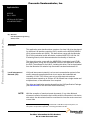
Application Note
AN2633/D
Rev. 1, 3/2004
Freescale Semiconductor, Inc...
LIN Drivers for SLIC Module
on the MC68HC908QL4
By: Matt Ruff
8/16 Bit Systems Engineering
Austin, Texas
Overview
This application note describes three versions of a slave LIN driver developed
for the slave LIN interface controller (SLIC) module on the MC68HC908QL4
(QL4) microcontroller unit (MCU). The slave driver comes with the Motorola
QL4 LIN kit evaluation board, which also contains AN2573/D: LIN Kits LIN
Evaluating Boards, which demonstrates the functionality of the driver.
The slave driver also comes with the M68EVBQL4 evaluation board (EVB)
from Metrowerks, along with a compatible version of the application code for
the EVB. The software for the LIN kit, including this driver, can be downloaded
from the Motorola LIN website: http://motorola.com/semiconductors/LIN
Local Interconnect
Network (LIN)
LIN (local interconnect network) is a low-cost communication protocol often
used in automotive applications that do not require the bandwidth and
versatility of CAN. The LIN bus uses only a single data wire and can
communicate at speeds up to 20 kbps. A LIN network has a single master and
multiple slaves, so bus arbitration is not required.
The driver and application was developed from the LIN Specification Package.
(See References for this and other useful resources.)
NOTE:
With the exception of mask set errata documents, if any other Motorola
document contains information that conflicts with the information in the device
data sheet, the data sheet should be considered to have the most current and
correct data.
Cyclone and MultiLink are registered trademarks of P&E Microcomputer Systems, Inc.
This product incorporates SuperFlash technology licensed from SST.
© Freescale Semiconductor, Inc., 2004. All rights reserved.
For More Information On This Product,
Go to: www.freescale.com
© Motorola, Inc., 2004
Freescale Semiconductor, Inc.
AN2633/D
Freescale Semiconductor, Inc...
SLIC Module
The SLIC module automates many LIN bus functions, allowing more of the
CPU and memory resources to be used for the user application. This
application note compares CPU and memory usage details among
timer-based, UART-based solutions, and SLIC-based solutions.
Other SLIC module features include:
• Automatic LIN frame synchronization
• Autobauding up to and well exceeding LIN standard bus speeds
• LIN error detection
• LIN message handling
• Automatic checksum generation and verification (for both types)
• ID parity checking
The SLIC module is compatible with LIN 1.3 and LIN 2.0 and requires almost
no configuration code and very minimal driver code. More details of the SLIC
module are explained in SLIC Module Operation, Features, and Benefits.
The driver has been evaluated at 9.615 kbps, 10.417 kbps, and 19.230 kbps.
LIN Communication
A LIN network consists of a single master node and up to 15 slave nodes.
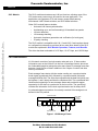
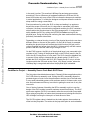
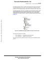
Information sent on the LIN bus is in the form of message frames, which can
be of selectable length but always have the same format. A message frame has
between 1 and 8 bytes of data in addition to the 3 bytes of control and data
security information.
Each message frame starts with the master sending out a synchronization
break signal (synchbreak field), followed by a synchronization field and a
message identifier field. The slave then responds with the data field (which can
be between 1 and 8 bytes) and then the checksum field. The synchbreak field
identifies the beginning of a new message frame and provides a regular
opportunity for the slave to synchronize on the bus clock. The synch field
contains the information for the clock synchronization and is always 0x55.
An acknowledgement procedure for correctly received LIN messages is not
defined in the LIN protocol.
MESSAGE FRAME
HEADER
SYNCH
BREAK
INTER-FRAME
SPACE
OR BREAK
RESPONSE
SYNCH INDENT
FIELD
FIELD
DATA
FIELD
IN-FRAME
RESPONSE SPACE
DATA
FIELD
DATA
FIELD
DATA CHECKSUM
FIELD
FIELD
INTER-BYTE
SPACE
Figure 1. LIN Message Frame
2
LIN Drivers for SLIC Module on the MC68HC908QL4
For More Information On This Product,
Go to: www.freescale.com
Freescale Semiconductor, Inc.
AN2633/D
SLIC Module Operation, Features, and Benefits
SLIC Module Operation, Features, and Benefits
Freescale Semiconductor, Inc...
The SLIC module on the QL4 represents a level of hardware support for LIN
slave applications that offers unparalleled performance. This increased
performance enables LIN slave node designers to do much more with smaller
devices than possible with UART-based solutions.
True Autobauding
up to 120 kbps with
No Software
Changes
The SLIC module automatically performs two very important—but distinctly
separate—functions while establishing communication on the LIN bus:
•
Autosynchronization
•
Autobauding
Automatic LIN message frame synchronization (autosynchronization) is the
ability to detect an idle bus and correctly determine when a LIN message frame
header has begun.
In many standard UART solutions, this operation can prove problematic,
because it is possible to erroneously detect a 0x00 data character as a break
symbol, even when within LIN timing specifications. This can happen if the
driver software uses the standard UART break-detection circuitry without
actually measuring the length of the break symbol. (The ESCI on many
Motorola HC08 MCUs contains a feature controlled by a bit called the LINR bit
which prevents this error.)
Autobauding is the ability to derive the LIN bus speed from the synchronization
byte in the header. Autobauding is possible only if the header is synchronized
to the beginning of the message frame. The SLIC handles autobauding and
sets up to transmit or receive the rest of the message frame at this speed.
Then, the SLIC receives the identifier for the message frame and checks the
parity bits to ensure the data integrity of the identifier byte. No software
intervention is required until this point, when the ID is presented to the
application or driver software. The software performs a lookup and then
decides what to do for this message frame.
Because LIN was designed to use inexpensive RC oscillators, the SLIC module
was designed to allow an input clock tolerance of about ±50% and ensure that
the accuracy of LIN communication is ±1% or less. This wide range of clock
accuracy means that in any LIN slave application, it is not necessary to trim the
internal oscillator to establish and maintain LIN communications. (Motorola
internal RC oscillators, such as the one on the HC908QL4 device, typically
come from the factory with a guaranteed tolerance of ±25% before trimming.)
This also means that ROM devices are perfectly suited to be used without any
nonvolatile memory at all, because they would never need to store a trim value.
LIN Drivers for SLIC Module on the MC68HC908QL4
For More Information On This Product,
Go to: www.freescale.com
3
Freescale Semiconductor, Inc.
AN2633/D
High-Speed
Communications and
Factory Programming
The SLIC is also capable of high-speed operations without the need to change
driver code. It will automatically synchronize to LIN messages, up to 120 kbps
(depending on CPU speed and filter settings). This is especially useful for
downloading code in a factory programming environment.
Freescale Semiconductor, Inc...
To accommodate higher speed messages, changes may be required to
ensure:
•
that the digital receive filter is adjusted, which prevents filtering out valid
high-speed data
•
that the physical layer device (such as a MC33661 enhanced LIN
transceiver) slew rate control is adjusted to prevent attenuating the bits
of the high speed message
Smaller, Faster
Driver Code
Automation of many standard LIN communication functions allows for much
smaller and more efficient driver code, which frees up vital CPU and memory
resources. Smaller driver code means that devices with less memory can be
used in some applications. Applications that require a 4K FLASH when using
an ESCI or timer module might easily fit in a 2K FLASH device if using the SLIC
module. Even in a 2K FLASH device (such as HC908QL2), more than 90% of
the FLASH memory is available for the application to use.
Fewer Interrupts to
Service
Many applications, especially motor control systems, often have stringent
timing requirements to maintain adequate control.
To service the LIN communications, the SLIC module requires a maximum of
two interrupts for any standard LIN message frame (1 to 8 data bytes). If a
message header that the application does not need to handle arrives, the SLIC
module would require only one interrupt.
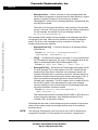
Compared to a UART-based solution, this reduction in interrupts can mean
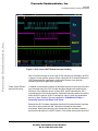
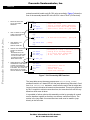
eliminating as many as 10 interrupts per message frame. Figure 2 shows the
interrupts required for servicing an 8-byte LIN request frame using both the
SLIC module and a traditional UART-based solution. Channel 1 (third trace
from top) of the scope capture shows the ISR firing on the SLIC module (two
interrupts required). Channel 4 (fourth trace from top — inverted polarity)
shows that 12 interrupts are required to service the same message with a
UART-based controller.
4
LIN Drivers for SLIC Module on the MC68HC908QL4
For More Information On This Product,
Go to: www.freescale.com
Freescale Semiconductor, Inc.
Freescale Semiconductor, Inc...
AN2633/D
SLIC Module Operation, Features, and Benefits
Figure 2. SLIC versus UART-Based Interrupt Handling
With 10 fewer interrupts to service (an 83.3% reduction in interrupts), the CPU
is free for a much greater amount of time. Using the SLIC module instead of a
UART-based solution significantly reduces the chance of an interrupt
interfering with other application operations.
Faster, More Efficient
Interrupt Servicing
In addition to reducing the number of interrupts required to service a LIN frame
(two interrupts only), the SLIC module has been designed to maximize the
efficiency of the interrupt service routine (ISR), which minimizes the CPU
requirements for LIN communications. A patented encoding method is used to
allow the ISR to service all SLIC interrupts in a short, fixed, and predictable
amount of time. Details of this are explained in CodeWarrior Project —
Assembly Source Code Basic SLIC Driver.
Because the SLIC module automates standard LIN communication functions,
less time is spent inside the ISR. Checksum calculations have been
automated, which eliminates the extra instructions that would be needed to
perform this calculation in a UART solution. This further reduces the amount of
LIN Drivers for SLIC Module on the MC68HC908QL4
For More Information On This Product,
Go to: www.freescale.com
5
Freescale Semiconductor, Inc.
AN2633/D
time spent inside the communications interrupt handlers. This time is valuable
because other interrupts cannot be handled during this time.
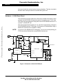
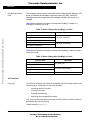
Hardware — LIN Kit Demo Board
The LIN kit demo board is made from a QL4 with an added LIN interface, which
consists of an MC33399 LIN transceiver and a 5-V regulator (an LT1121 chip).
The board can be programmed using either the RS-232 MON08 interface or a
Cyclone or MultiLink tool.
Freescale Semiconductor, Inc...
The board requires three jumpers (J2, J4, and J5) for programming it using the
RS-232 MON08 interface. The jumper J2 is however not needed when using a
MultiLink or Cyclone tool to program or debug.
NOTE:
~12 V
VBat
If you plan to use MON08 tools for debugging, you must avoid manipulating pin
PTA0 since that will disturb the communication with the tool.
8
1
LT1121
5V
3
5
100 kΩ
47 kΩ
100 kΩ
2.2 kΩ
1 kΩ
100 nF
J2
(MONITOR
MODE)
27 kΩ
LIN
6
7
VSup
8
INH
LIN
MC33399
3 WAKE
GND
5
10 kΩ
5
VDD
J4
7
5 V (DEBUG)
47 kΩ
8
RESET
A1
IRQ
RESET
6
PUSH-BUTTON
S1
9.1 V
ZENER
EN 2
13
Rx 1
16
Tx 4
15
B7
MC68HC908QL4
B4 (SLC Rx)
9
B0
B1 12
11
B2
14
B6
B5 (SLC Tx)
OSCILLATOR MODULE
2
(DEBUG)
OSC1
J5
VSS
4
GND
Figure 3. Schematic of QL4 LIN Kit Board
6
LIN Drivers for SLIC Module on the MC68HC908QL4
For More Information On This Product,
Go to: www.freescale.com
1 kΩ 1 kΩ 1 kΩ 1 kΩ
Freescale Semiconductor, Inc.
Freescale Semiconductor, Inc...
AN2633/D
Hardware — LIN Kit Demo Board
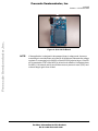
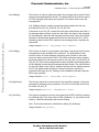
Figure 4. QL4 LIN Kit Board
NOTE:
If the application is designed to be powered down in sleep mode, there are
some things to consider when using the QL4 LIN kit board. Because the voltage
regulator is connected to the INH pin of the MC33399 physical layer, if the EN
pin (connected to PTB7 of the MCU) is driven low in software, it will power down
the MCU. LIN network activity would then cause a power-on reset (POR) and
code will begin again from scratch.
LIN Drivers for SLIC Module on the MC68HC908QL4
For More Information On This Product,
Go to: www.freescale.com
7
Freescale Semiconductor, Inc.
AN2633/D
Hardware — M68EVB908QL4 Evaluation Board
The QL4 evaluation board is made from a QL4 with an added enhanced LIN
interface, which consists of an MC33661 enhanced LIN transceiver and a 5-V
regulator (an LT1121 chip). The board can be programmed either using the
RS-232 MON08 interface or a Cyclone/MultiLink tool.
Freescale Semiconductor, Inc...
The primary difference between the EVB and the LIN kit board is the
connection of inputs and outputs. There is only one LED (D1) on the EVB,
which is used for displaying the least significant data bit. This bit is inverted in
software to accommodate the circuitry differences in the boards, keeping the
interface consistent so that a logic 1 turns on the LED.
The other three bits of data, which are output to LEDs D7, D6, and D5 on the
LIN kit board, are still brought out to PTB1, PTB2, and PTB6, respectively.
The input button is used differently on the LIN kit board and EVB. Because
there is not a dedicated button for the application on the EVB, the reset button
is reused. Because the reset function on the QL4 device isn’t active unless
activated by software in user mode, there is no problem using this button for the
application.
Another major difference with running application code on the EVB is the
presence of the enhanced LIN transceiver (MC33661). This allows the
possibility of controlling the physical layer slew rate through software control of
the enable (EN) pin of the device. Operation of this feature is beyond the scope
of this application note. Refer to the documentation for the MC33661 device for
more information.
8
LIN Drivers for SLIC Module on the MC68HC908QL4
For More Information On This Product,
Go to: www.freescale.com
Freescale Semiconductor, Inc.
Freescale Semiconductor, Inc...
AN2633/D
Hardware — M68EVB908QL4 Evaluation Board
Figure 5. Schematic of M68EVB908QL4 Evaluation Board
Figure 6. M68EVB908QL4 Evaluation Board
LIN Drivers for SLIC Module on the MC68HC908QL4
For More Information On This Product,
Go to: www.freescale.com
9
Freescale Semiconductor, Inc.
AN2633/D
The EVB does not support the regulator inhibit function by the physical layer,
so this must be taken into account when using software that handles sleep
mode. Care must be taken to ensure that the SLIC module is disabled before
disabling the physical layer because recovery from sleep will not result in POR.
Sleep mode recovery would then need to re-enable the physical layer first, then
re-enable the SLIC module. Details of this are beyond the scope of this
application note.
Freescale Semiconductor, Inc...
SLIC Driver Code – Three Versions
Three different versions of the SLIC driver code are included in this application
note to illustrate several different ways to implement software drivers for this
module. All methods serve the same basic purpose, but every method is a
different balance of code portability, readability, and efficiency. The primary
difference between each version of the driver code is how the SLIC module ISR
is written.
The three basic versions of the code are:
•
Assembly code version of the SLIC ISR
•
Basic C-based version of the same ISR
•
C-based driver with a standardized application programmers interface
(API). The API is designed to match the API for the QT/QY LIN slave
drivers described in AN2599/D.
All versions of the code include a sample application designed for use with
either the LIN kit QL4 slave evaluation board or the M68EVB908QL4
evaluation board. To indicate which hardware will be used, uncomment the
appropriate #define statement at the beginning of the ‘slave.c’ file in the
project.
// -Use only one of the following define statements -//#define QL4LINKit
// Use this define for the QL4 LINkit Board
#define QL4EVB
// Use this define for the QL4 EVB Board
The sample application responds to message IDs designed for the LIN kit
application demo boards. The messaging and details regarding this are
explained more fully in AN2573/D: LIN Kits LIN Evaluation Boards. The ASM
and C versions are designed to respond to only the default IDs. The API version
allows the user to dynamically change the ID at runtime (as described in
AN2573/D).
One key feature in all versions is a sleep mode function, which turns off the
LEDs when no activity has been detected on the bus or button for a long time.
Sleep mode is implemented by regularly calling the Check_LIN_Sleep() routine
10
LIN Drivers for SLIC Module on the MC68HC908QL4
For More Information On This Product,
Go to: www.freescale.com
Freescale Semiconductor, Inc.
AN2633/D
CodeWarrior Project — Assembly Source Code Basic SLIC Driver
Freescale Semiconductor, Inc...
in the main() routine. This monitors LINSleep flag and sets power states
accordingly. Due to differences in hardware between the EVB and LIN kit
board, this routine only turns off the LEDs to indicate the sleep mode condition.
In actual applications, it is likely the designer would power down the node for
sleep mode for energy conservation.
Exact procedures for putting the SLIC to sleep and waking it up again are
beyond the scope of this note, but it is important to remember a few basic
concepts. Like many communication peripheral modules, the SLIC contains a
state machine that synchronizes to the LIN message traffic. It is important to
safely disable the SLIC by writing the INITREQ bit before turning off the
physical layer. Doing this will avoid confusing the state machine and inducing
potentially undesirable side effects.
Depending on external circuitry, turning off the physical layer device can have
different effects on the rest of the system. On the LIN kit board, for example,
disabling the physical layer will activate the inhibit function (INH pin) on the
voltage regulator and power down the MCU. LIN bus activity will then restore
power to the MCU and the code will go through a POR.
On the EVB, however, the INH pin of the physical layer is not connected to the
regulator at all. Turning off the physical layer on the EVB will result in the Rx
line to the SLIC being driven to a low state. The SLIC should be disabled first,
to prevent it from trying to interpret this as a break symbol. Do NOT try to
disable the SLIC from within the SLIC ISR. Disable the SLIC only in a code
location outside the ISR such as the Check_LIN_Sleep() routine, where the
LINSleep flag is recognized and before the physical layer is disabled.
CodeWarrior Project — Assembly Source Code Basic SLIC Driver
The first project described shows a basic C-based LIN slave application with a
SLIC ISR written in assembly code. Writing the ISR in assembly allows the
greatest degree of control over the performance and the size of the final code.
In very small embedded systems, such as those used in LIN slave nodes, code
size and performance efficiency are critical to getting the most out of very few
resources.
One of the key features of handling the ISR in assembly code is to use the
design of the SLIC module to ensure maximum execution efficiency. The SLIC
state vector register (SLCSV) is encoded to allow the user to build a jump table.
When using a jump table, no matter what interrupt source is being serviced, the
ISR will begin servicing the interrupt in a fixed amount of time.
The SLCSV register value is loaded into the index register, then used as an
offset into the jump table. The entries in the jump table point to service handler
LIN Drivers for SLIC Module on the MC68HC908QL4
For More Information On This Product,
Go to: www.freescale.com
11
Freescale Semiconductor, Inc.
AN2633/D
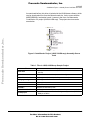
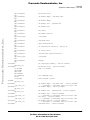
subroutines which handle each SLCSV value accordingly. Figure 7 shows the
flow of the assembly based ISR with a SLCSV value of 0x2C (ID Received).
1
jmptab:jmp serv0x00
nop
...
jmp serve 0x2C
nop
...
jmp serve 0x3C
nop
3
JUMP DIRECTLY TO
APPROPRIATE
SERVICE HANDLER
4
SERVICE THE INTERRUPT
SOURCE AS NEEDED
NOTE:
REGARDLESS OF THE
LOCATION OF THIS CODE,
IT ALWAYS TAKES TWO
jmp INSTRUCTIONS TO
BEGIN EXECUTING.
5
serve0x2C:
lda
cmp
bne
...
jmp
SLCID
LINID
next_id_l
Push H onto stack
clear H to ensure proper addressing
Load SLCSV value into index register
SLCSV used as offset into jump table
; No interrupts pending
; ID Received Successfully - parity OK
; Wakeup
ID Received Successfully - parity OK - ser
Performing ID lookup to determine message
Load up ID of incoming message
Is it the ID we’re looking for?
If not, check for next ID
;
;
;
;
Load mask for SLCF bit
Clear SLCF bit
restore from stack
return from interrupt
exit_isr
exit_isr:
WHEN FINISHED, JUMP TO
COMMON EXIT CODE WHICH
lda SLCS
CLEARS THE INTERRUPT
ora #mSLIC
FLAG. tHIS SAVES ROM SPACE.
sta SLCS
IF DESIRED, THIS CODE CAN
pulh
BE INCLUDED AT THE END
rti
OF EACH SERVICE HANDLER
EXIT
;
;
;
;
;
SERVICE HANDLER
Freescale Semiconductor, Inc...
JUMP TO ENTRY IN JUMP
TABLE FOR INTERRUPT
SOURCE IN SLCSV.
;
;
;
;
JUMP TABLE
slic_isr:
pshh
clrh
ldx SLCSV
jmp jmptab.x
ENTRY
2
ENTER ISR AND LOAD
SLCSV INTO INDEX
REGISTER.
Figure 7. SLIC Assembly ISR Flowchart
The jump table serves the same purpose as a switch(temp_SLCSV)
statement would in a C-based ISR, but the jump table always executes in fixed
time. In a switch(var) statement, cases near the end of the list might take
longer to execute, because all cases must be searched. This may be optimized
by the C compiler to minimize execution time, but execution time will still vary
based on which case is taken.
It is possible to further optimize this assembly routine by grouping all unused
service handlers together so that they can share a common exit point. The
entries in the jump table for unused services could even be made to jump
directly to the exit code.
12
LIN Drivers for SLIC Module on the MC68HC908QL4
For More Information On This Product,
Go to: www.freescale.com
Freescale Semiconductor, Inc.
AN2633/D
CodeWarrior Project — Assembly Source Code Basic SLIC Driver
Freescale Semiconductor, Inc...
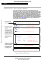
As mentioned before, this driver is included in the LIN Kit demo software, which
can be downloaded free from the Motorola web site. It also comes with the
M68EVB908QL4 evaluation board. It comes in the form of a Metrowerks
CodeWarrior 3.0 project (LINQL4-ASM.mcp). The project structure can be
seen below:
Figure 8. CodeWarrior Project (LINQLY-ASM.mcp) Assembly Source
Code
Table 1. Files in LINQL4-ASM.mcp Sample Project
File
Description
SLIC.asm
Contains the main driver code (The LIN driver is contained in the
one file)
global.h
Global variable declarations (not used heavily)
MC68HC908QL4.h
MCU register definition header file (non-standard)
QL4_registers_v0r2.inc
ASM register definitions file
slave.c
Main application code
vector.c
MCU vector definitions
Start08.c
Standard HC08 startup code
MC68HC908QL4.C
MCU register data structure instantiations file (also non-standard)
hc08ql4.prm
CodeWarrior parameter file for defining memory locations (ROM and
RAM) in the MCU
LIN Drivers for SLIC Module on the MC68HC908QL4
For More Information On This Product,
Go to: www.freescale.com
13
Freescale Semiconductor, Inc.
AN2633/D
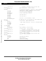
In the C and ASM versions of this code, the same basic functions are
performed. The C ISR, in this case, is just a few bytes smaller than the ASM
ISR. This is primarily due to the efficiency of the CodeWarrior compiler and the
fact that there is not much code to handle many of the different cases. The
switch()statement in the C ISR is very sparsely populated and the compiler is
able to optimize very heavily. In more elaborate driver code, with support for
more messages and features, it is likely that the C version would become larger
than the ASM version. Figure 9 shows the flow of the C based ISR with a
SLCSV value of 0x2C (ID Received).
1 ENTER ISR AND LOAD
SLCSV INTO TEMPORARY
VARIABLE.
void SLIC_ISR(void)
...
temp_SLCV = SLCVS;
EXECUTION TIME OF THIS
WILL VARY DEPENDING
ON HOW MANY CASES
HAVE CODE, WHAT ORDER
CASES ARE LISTED IN,
AND THE EFFICIENCY AND
SETTINGS OF THE COMPILER.
case 0x2c;
...
//_ID received correctly - parity OK_
// Check ID
if(SLCID=LINID)
{
ID_found = 1;
SLCD0
= LINdata;
SLCD1
= 0;
SLCDLC
= 0xC1;
// Write DLC code to
// Start TX - STD Checksum
}
break;
...
}
SLCS_SLCF = 1;
//___end switch temp_SLCSV
// Clear SLIC interrupt flag
Figure 9. SLIC-Based ISR Flowchart
LIN Drivers for SLIC Module on the MC68HC908QL4
For More Information On This Product,
Go to: www.freescale.com
EXIT
} //___________________________end_SLIC_ISR_________
14
OTHER
“CASES”
4 WHEN FINISHED, JUMP TO
COMMON EXIT CODE WHICH
CLEARS THE INTERRUPT
FLAG. THIS SAVES ROM.
SPACE IF DESIRED, THIS
CODE CAN BE INCLUDED
AT THE END OF EACH
SERVICE HANDLER
// Set ID found flag
// Load TX buffers
SERVICE HANDLER FOR
CURRENT INTERRUPT SOURCE
3 WHEN FOUND, EXECUTE
THE CODE FOR THE
APPROPRIATE SERVICE
HANDLER.
switch(temp_SLCSV)
// Switch is temporary measure
{
case 0x00;
//_______No interrupts pending_______
break;
case 0x08;
//___TX Buffer Empty - Checksum sent_
break
...
case 0x28;
//_______Byte Framing Error_______
break;
OTHER SERVICE
HANDLER “CASES”
2 TRAVERSE THE SWITCH()
CASES UNTIL A MATCH
IS FOUND.
// Read SLCVS value
ENTRY
Freescale Semiconductor, Inc...
CodeWarrior Project — C Source Code Basic SLIC Driver
Freescale Semiconductor, Inc.
AN2633/D
CodeWarrior Project — C Source Code Basic SLIC Driver
An additional feature of the C version of the basic driver is that it will accept a
2-byte message with an ID of 0x97. This is shown as an example of how to
handle a LIN command message, where data is coming from the master node.
Freescale Semiconductor, Inc...
As mentioned before, this driver is included in the LIN kit demo software, which
can be downloaded free from the Motorola web site. It also comes with the
M68EVB908QL4 evaluation board. It comes in the form of a Metrowerks
CodeWarrior 3.0 project (LINQL4-C.mcp). The project structure can be seen in
Figure 10.
Figure 10. CodeWarrior Project (LINQL4-C.mcp) C Source Code
The LIN driver consists of two files:
•
SLIC_LINdriver.c — contains the main driver code
•
SLIC_LINdriver.h — header file for the driver
The other files serve the same functions as they do in the assembly version
project.
LIN Drivers for SLIC Module on the MC68HC908QL4
For More Information On This Product,
Go to: www.freescale.com
15
Freescale Semiconductor, Inc.
AN2633/D
CodeWarrior Project — C Source Code SLIC Driver with API
The API version of the code is designed to provide essentially the same
interface as the one contained in AN2599/D for QT/QY LIN slave drivers.
Freescale Semiconductor, Inc...
As mentioned before, this driver is included in the LIN kit demo software, which
can be downloaded free from the Motorola web site. It also comes with the
M68EVB908QL4 evaluation board. It comes in the form of a Metrowerks
CodeWarrior 3.0 project (LINQL4-API.mcp). The project structure can be seen
below:
Figure 11. CodeWarrior Project (LINQL4-API.mcp) — C Source Code with
Standard API
The LIN driver consists of four files:
Table 2. Files in LIN Driver
File
Description
SLIC_LINdriver.c
contains the main driver code(1)
LINapi.c
contains all the driver API functions
LINmsg.c
where all LIN message frames are
defined
SLIC_LINdriver.h
header file for the driver
1. This is a different file than the one in the C project
16
LIN Drivers for SLIC Module on the MC68HC908QL4
For More Information On This Product,
Go to: www.freescale.com
Freescale Semiconductor, Inc.
AN2633/D
CodeWarrior Project — C Source Code SLIC Driver with API
Freescale Semiconductor, Inc...
The SLIC_LINdriver.c file used in the API version is different and more generic
for the API project than for the C project. It is designed to work with the
LINmsg.c file to search for messages, rather than hard coding them directly into
the interrupt service routine as the C project does.
The structure of LINmsg.c is very similar to the one used in AN2599/D with one
important difference. The SLIC module contains a register called the SLIC Data
Length Code register (SLCDLC) which encodes the number of bytes in a
message frame, the type of checksum calculation to be used (standard or
enhanced), and whether the SLIC is to transmit or receive this frame. To
simplify the ISR code for the API version, a data structure in LINmsg.c called
MessageDLCTbl[] contains the appropriate value for this register for each
message defined. This MessageDLCTbl[]replaces the function of
MessageCountTbl[] in the AN2599/D drivers.
The other files serve the same functions as they do in the assembly and C
projects.
How to Use the API
Driver
The easiest way to begin developing a new application is to use the API sample
project. To do this, simply replace the sample application file slave.c with your
own application code. You can also begin developing by creating a new project
in a CodeWarrior development environment and adding the four LIN driver files
to the project. Then:
1.
Define the messages you want to use, in the LINmsg.c file, as described
below.
2.
Make sure the vectors (_Startup() uses vector 0 and SLIC_ISR() uses
vector 10) are set up properly, either in the vector.c file or in a parameter
file.
3.
Don’t forget to #include the file LINdriver.h in your application code file.
API Driver
Configuration
The driver configuration file, LINmsg.c, can be edited by the user. It contains
definitions of all messages to be recognized by the application and is set up for
the demo code to recognize all four possible IDs for the demo application.
Setting up this file is all that is needed for configuration of the API driver for
normal LIN applications.
Message File
Configuration
All LIN message frames that the slave node is to use in the application must be
defined in the LINmsg.c file.
LIN Drivers for SLIC Module on the MC68HC908QL4
For More Information On This Product,
Go to: www.freescale.com
17
Freescale Semiconductor, Inc.
AN2633/D
•
Message buffers — Define one array for each message frame that
either requires a response or must be received. When defining, it is good
practice to include the frame ID in the name (for example,
“Message0xID”, where ID is the message identifier in hexadecimal with
the parity bits included).
This buffer is for the frame data field for each message. The data field
can be 1 to 8 bytes. The array size must equal the number of data bytes
for that message. An example of a 2-byte message could be:
U8 volatile Message0xD8[2];
Freescale Semiconductor, Inc...
After message buffer storage has been created for all messages that will be
recognized by the node, these must be included in a number of additional
arrays. The order of the messages must be consistent in all arrays. The
following three arrays are required:
•
MessagePointerTbl[] — Consists of pointers to all message buffers
defined above.
Example: U8 volatile * MessagePointerTbl[] =
{Message0xD8, Message0x99,…};
•
IdTbl[] — Contains all IDs relevant to this node. It is very important that
the ID includes the parity bits. The order of the messages must be the
same as in MessagePointerTbl[] and MessageDLCTbl[].
Example: U8 const near IdTbl[] = {0xD8, 0x99,…};
•
MessageDLCTbl[] — Defines the SLIC data length code register values
for each message. This control register in the SLIC module tells the
hardware how many bytes of data are in the message, shows if the
message should be sent or received by the slave, and what method of
checksum calculation should be used to ensure data integrity. LIN 2.0
allows for standard or enhanced checksum, where the ID byte is
included in the calculation. This DLC register value is copied directly to
the SLCDLC register at the appropriate time during the message
interrupt handling to send or receive data for this message frame with
the proper checksum calculation method.
Example: U8 volatile near MessageDLCTbl[] =
{0xC1,0x44,0x47,…};
This example shows that the message with ID 0xD8 (in IdTbl above) is
2 bytes long (plus checksum), uses standard checksum (ID not
included), and it is defined for sending.
Remember that the order of the messages must be consistent in all previous
tables. All the arrays (except the message buffers) must to be named as
described above.
NOTE:
18
The data type U8 frequently used in the driver and its API is defined as an
unsigned 8-bit number. For this compiler this is done as “unsigned char.”
LIN Drivers for SLIC Module on the MC68HC908QL4
For More Information On This Product,
Go to: www.freescale.com
Freescale Semiconductor, Inc.
AN2633/D
CodeWarrior Project — C Source Code SLIC Driver with API
API
The API that comes with the driver makes it easier for the application developer
to interface to the driver, as it is not necessary to know anything about the
communications protocol behind how messages are sent and received. Most
of this is handled by the SLIC module autonomously, so there is not much
behind the API, but it does provide an abstraction layer between low-level
driver and application. This section describes an overview of the functions and
constants used in the API.
Freescale Semiconductor, Inc...
The API includes status constants that describe:
•
Status of the service calls (such as sending or receiving)
•
Status of individual messages (such as empty, updated, or overrun)
Table 3. LIN Message Status Constants
Constant
Description
LIN_OK
Value
Service call succeeded without any error
0x00
The ID requested is defined for the node, but for the opposite
direction (sending/receiving)
0x80
LIN_NO_ID
The message ID requested is not defined for this node
0x7F
LIN_INVALID_MODE
The service couldn’t be called in the current driver state
0x16
LIN_ INVALID_ID
Table 4. LIN Message Status Flow
Constant
Description
Value
LIN_MSG_NODATA
The data buffer for this message is empty, i.e,. data has not
been initialized or received yet
0x01u
Message data OK, i.e. not overrun and not empty
0x10u
The message data has not changed since last read/written
0x02u
LIN_MSG_UPDATED
Message data has been updated
0x20u
LIN_MSG_OVERRUN
The message data has not been read and was overwritten
0x04u
LIN_MSG_OK
LIN_MSG_NOCHANGE
LIN Drivers for SLIC Module on the MC68HC908QL4
For More Information On This Product,
Go to: www.freescale.com
19
Freescale Semiconductor, Inc.
AN2633/D
LIN Message Status
Flow
The message status is stored in the table called LinMsgStatus[]. When the LIN
driver is initialized all messages will get the status LIN_MSG_NODATA.
Message status will change when the message is being sent, received, or
updated.
Table 5 demonstrates the change of status after PutMsg() is called or a
message is received at a node.
Table 5. Status Change after PutMsg() is Called
Previous State
Next State
Freescale Semiconductor, Inc...
LIN_MSG_NODATA
LIN_MSG_OK
LIN_MSG_UPDATED
LIN_MSG_NOCHANGE
LIN_MSG_UPDATED
LIN_MSG_OVERRUN
LIN_MSG_OVERRUN
Table 6 demonstrates the change of status after GetMsg() is called or data is
sent from a node.
Table 6. Status Change after GetMsg() is Called
Previous State
LIN_MSG_UPDATED
LIN_MSG_OVERRUN
LIN_MSG_OK
LIN_MSG_NOCHANGE
LIN_MSG_NODATA
Next State
LIN_MSG_OK
LIN_MSG_NOCHANGE
LIN_MSG_NODATA
API Functions
LIN_Init()
This function initializes the LIN driver and makes the driver ready to detect LIN
communication. Initialization of the driver includes:
•
Initializing the SLIC module
•
Clearing error flags
•
Clearing the sleep flag
•
Initializing the message buffer status
LIN_Init() must be called before any other LIN API function is called. It takes no
parameters and returns nothing.
Usage example: LIN_Init();
20
LIN Drivers for SLIC Module on the MC68HC908QL4
For More Information On This Product,
Go to: www.freescale.com
Freescale Semiconductor, Inc.
AN2633/D
CodeWarrior Project — C Source Code SLIC Driver with API
LIN_GetMsg()
This function is used for getting the data of the message with a certain ID and
copying its message data into a buffer. The parameters for this function are the
ID of the message (with parity) and a pointer to the buffer where to put the
message data.
Freescale Semiconductor, Inc...
LIN_GetMsg() returns a status constant describing whether the call was
successful (LIN_OK, LIN_INVALID_ID, LIN_NO_ID).
If the status is not LIN_OK, no data will have been retrieved from the buffer. If
the message data has been copied into the buffer, the status of the message
will be changed to show that the message has been read. Frame-level atomic
operation is automatically guaranteed by the fact that while the SLIC_ISR is
transferring data from the SLIC module to the message buffer, interrupts are
suspended.
Usage example: status = LIN_GetMsg (0x99, MsgData);
LIN_PutMsg()
This function is used for copying data to send from a temporary buffer into the
message data of the message with a certain ID. The parameters for this
function are the ID of the message (with parity) and a pointer to the buffer
where the data to send can be found. The function returns a status constant
describing whether the call was successful or not (LIN_OK, LIN_INVALID_ID,
LIN_NO_ID). When the message data has been updated, the message status
will be changed to show that the message has been written. The call itself does
not send any data on the LIN bus, however the next time the master requests
this ID, the updated data will be sent. Frame-level atomic operation is
guaranteed because the LIN_PutMsg() routine disables interrupts during the
buffer copy operation.
Usage example: status = LIN_PutMsg (0x1A, MsgData);
LIN_MsgStatus()
This function returns the current status of the specified message. It takes the
message ID (with parity) as a parameter. If the ID is not defined, the function
will return LIN_NO_ID.
Usage example: msgstatus = LIN_MsgStatus (0x1A);
LIN_GotoRun()
This function changes the current driver state from SLEEP to RUN by clearing
the LINSleep flag. If the driver state is RUN (LINSleep = 0), the function does
nothing. It takes no parameters and returns nothing.
Note: This function should be called before calling LIN_Wakeup().
Usage example: LIN_GotoRun();
LIN Drivers for SLIC Module on the MC68HC908QL4
For More Information On This Product,
Go to: www.freescale.com
21
Freescale Semiconductor, Inc.
AN2633/D
LIN_Wakeup()
LIN_Wakeup() issues the LIN wake-up signal, which consists of eight dominant
bits (including start bit) followed by at least four recessive bits (including stop
bit and a recessive pause).
Freescale Semiconductor, Inc...
This function uses the WAKETX bit feature of the SLIC module to send a single
wake-up signal on the bus. No wake-up signal is sent if the driver is in SLEEP
state (the LINSleep flag is set) because the LIN_GotoRun() function should
have been called before, which changes the state to RUN (clear LINSleep = 0).
After the wake-up signal is sent, there should be a SynchBreak and
communication should resume from the master.
LIN_Wakeup() takes no parameters. There are two possible return values,
either LIN_OK (the wake-up signal was successfully sent) or
LIN_INVALID_MODE (if the current driver state is SLEEP).
Usage example: status = LIN_Wakeup();
Error Handling
The driver detects two types of errors in the LIN message — bit errors and
checksum errors.
A bit error is detected when a recessive bit is sent and a dominant bit is
detected on the bus. This indicates that the bus is controlled by another node
or shorted to GND. In either case, the transmission is aborted and the
BitERROR flag is set.
The SLIC automatically detects bit errors and this function in the ISR simply
sets the BitERROR flag in the API. The user must then clear the flag when the
BitERROR condition is handled (generally setting up for a re-transmission of
the corrupted error frame).
The node receiving data will calculate the checksum by doing a modulo-256
sum of the message data bits. This checksum must match the received
checksum. If not, the message is corrupt, and the receiving node will set the
ChecksumERROR flag and ignore the received data.
As with the bit error, checksum errors are automatically detected by the SLIC
module, then the ISR simply sets the ChecksumERROR flag. Note that a
checksum error might occur if the message DLC value in the MessageDLCTbl[]
array in LINmsg.c was set incorrectly.
The error flags are single bit field values that are set by the driver (set to 1) and
cleared by the application code (set to 0). The flags are global and can be
polled in the application to check whether there is an error during send or
receive.
Table 7 provides a description of bit errors and checksum errors.
22
LIN Drivers for SLIC Module on the MC68HC908QL4
For More Information On This Product,
Go to: www.freescale.com
Freescale Semiconductor, Inc.
AN2633/D
Driver Performance — Timer, UART, and SLIC Compared
Table 7. Error Descriptions
Flag
Freescale Semiconductor, Inc...
Sleep Mode
Description
BitERROR
Set if there is a bit error when sending
ChecksumERROR
Set if there is a checksum error while receiving
The LIN protocol includes a sleep mode, which reduces system power
consumption. A message with ID 0x3C and first data byte of 0x00 is used to
broadcast the Sleep Mode command. The API driver will respond to this sleep
mode message by setting the sleep flag (LINSleep). As stated before, the
method of putting the module in sleep mode is hardware/design dependent and
is therefore handled by the application code.
Driver Performance — Timer, UART, and SLIC Compared
The following performance data compares various methods of implementing
LIN communications with different hardware and software options. All are
based on using the same basic application found in the LIN kits demonstration
software (modified to accommodate an 8-byte message). This data allows the
developer to balance cost, performance, and other MCU features for a specific
application.
One of the key advantages to the SLIC module is its ability to simplify user
application code. Table 8 shows the RAM and ROM usage of the various
implementations, along with the QY bit-banged driver using a timer channel
and an ESCI version. These numbers show the memory usage for the LIN kit
application.
LIN Drivers for SLIC Module on the MC68HC908QL4
For More Information On This Product,
Go to: www.freescale.com
23
Freescale Semiconductor, Inc.
AN2633/D
SLIC
Freescale Semiconductor, Inc...
ESCI
TIM08
Table 8. Driver Performance Metrics
Version
Std
API
Feature
Level
QY/QT bit-banged
drivers
AN2503/D(1)
N
QY/QT bit-banged
drivers
AN2599/D
Y
—
EY16 ESCI
drivers
AN2575/D(2)
Y
LINQL4-ASM
Driver Code Resource Required
ROM (Bytes)
Stack
(Bytes)
536 (+ 3 per msg)
22
836 (+ 3 per msg)
22
32 (+12 per 8 byte
msg)
1103 (driver)
487 (API)
35
—
19 (+1 per 8 byte
msg)
1130
(driver + API)
< 25
N
—
11
(+ 8 per 8 byte msg)
172
7
LINQL4-C
N
—
18
(+ 8 per 8 byte msg)
120
20
LINQL4-API
Y
—
32
(+ 12 per 8 byte msg)
838 (driver)
420 (API)
35
MIN
MAX
RAM (Bytes)
24 (+ 8 per 8 byte
msg)
1. AN2503/D driver assumptions:
MIN = external OSC, 9600 bps, no SLEEP mode, no parity check, no bit error checking
MAX = internal OSC, 19200 bps, SLEEP, parity checking, and bit error checking enabled
Each also has 7 messages defined, using 26 bytes of RAM
2. AN2575/D memory usage data comes from LIN08 driver manual for EY16.
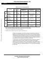
Another key advantage to the SLIC is its ability to dramatically reduce the
number of required interrupts and the time spent in servicing those interrupts.
Table 9 shows a relative comparison of the CPU and interrupt loading impacts
of the SLIC and various other driver implementations. All have been normalized
to 3.2 MHz operation and 8-byte messages to accurately compare the relative
performance of each hardware and software combination.
In the QL4 MCU, the internal oscillator speed may be increased to 6.4 MHz by
setting the bus frequency select bit (BFS) in the oscillator status register
(OSCSTAT). This will further reduce the CPU loading by cutting ISR execution
times in half. This means that it is possible to reduce the average CPU usage
on the QL4 to below 0.1% and peak usage to 17 µs for an 8-byte LIN message
at 9615 bps.
24
LIN Drivers for SLIC Module on the MC68HC908QL4
For More Information On This Product,
Go to: www.freescale.com
Freescale Semiconductor, Inc.
AN2633/D
Driver Performance — Timer, UART, and SLIC Compared
Table 9. Driver Performance Metrics
Version
TIM08
ESCI +
TIM08
No. of
Interrupts/
Msg Frame
(8-byte msg)
LIN Bus
Speed
CPU Speed
(MHz)
CPU Usage(1)
Average(2)
9,615
14% (rx)
20% (tx)
AN2503/D
19,230
29% (rx)
40% (tx)
QY/QT bit-banged
drivers
9,615
20% (rx)
20% (tx)
AN2599/D
19,230
38% (rx)
44% (tx)
EY16 ESCI
drivers
9,615
2% (rx)
4% (tx)
QY/QT bit-banged
drivers
(3)
N
111 Rx
120 Tx
Y
N
97 Rx
106 Tx
272 µs
3.2(4)
(calculated)
12
AN2575/D
39 µs
19,230
4% (rx)
7% (tx)
9,615
0.3 (rx)
0.2 (tx)
19,230
0.5 (rx)
0.5 (tx)
9,615
0.4 (rx)
0.4 (tx)
34 µs
N
AN2633/D
LINQL4-C
N
AN2633/D
LINQL4-API
2
61 µs
3.2
19,230
0.8 (rx)
0.8 (tx)
9,615
0.8 (rx)
0.8 (tx)
19,230
1.6 (rx)
1.7 (tx)
123 µs
Y
AN2633/D
Peak
193 µs
3.2
LINQL4-ASM
SLIC
Freescale Semiconductor, Inc...
Std
API
1. CPU usage represents the time spent in the communication ISR(s) vs. time spent doing other tasks. API functions and
handling performed outside of the ISR(s) is not counted against this metric. Average value is reported as a percentage of
times, but is still a function of CPU speed, as LIN communications is asynchronous to CPU operations. CPU usage
numbers are approximate. Peak time represents the longest single interrupt that must be processed.
2. From LIN08 Driver User's Manual: CPU performance is calculated as: L = T active / T frame * 100%
where:
- L is the CPU load in percent;
- T active is the amount of CPU time expended in executing the driver code during T frame;
- T frame is the amount of time required to transmit or receive a regular LIN bus frame of maximum length, containing
8 bytes of data (124 bits). The required LIN message budget of 40% is also taken into account. For Reference: T frame
(9615 bps) = 18.055 ms; T frame (19230 bps) = 9.028 ms.
3. For received data (command) messages, 0x55 data and checksum used for worst case ISR load.
4. EY16 CPU usage information was measured based on 4.9152 MHz CPU frequency, then recalculated for a 3.2 MHz CPU
frequency.
LIN Drivers for SLIC Module on the MC68HC908QL4
For More Information On This Product,
Go to: www.freescale.com
25
Freescale Semiconductor, Inc.
AN2633/D
Freescale Semiconductor, Inc...
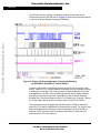
The difference in the number of interrupts serviced is best seen on an
oscilloscope showing the ISR pulses. Figure 12 shows the interrupts required
to service an 8-byte request message at 9600bps.
Figure 12. 8-Byte LIN Request Message and Interrupt Handling
for HC908QY4, HC908EY16, and HC908QL4
Channel 1 shows the LIN message as seen at the RX pin of the QL4 slave
device. Channel R1 is a stored waveform showing the 106 interrupts required
to bit bang the message. The interrupts seem to extend past the end of the
message frame, but this is due to the delay between the ID lookup and the
beginning of the slave's response. Channel R2 is also a stored waveform
showing the 12 interrupts required for an EY16 based slave. Channel 3 shows
the 2 interrupts required by the QL4 slave node with the SLIC module.
This performance data suggests that the QL4 and EY16 MCUs are better
suited for CPU-intensive applications (such as motor control). For simpler, less
time-critical applications (such as contact monitoring), the QY4 should be
sufficient. MCU selection must be made by balancing cost and resource
requirements of CPU and memory.
26
LIN Drivers for SLIC Module on the MC68HC908QL4
For More Information On This Product,
Go to: www.freescale.com
Freescale Semiconductor, Inc.
AN2633/D
References
References
MC68HC908QL Data Sheet, Motorola Document Number: MC68HC908QL4/D
LIN Specification Package, Rev.1.3, Dec. 12, 2002
LIN Specification Package, Rev.2.0, Sept. 16, 2003
AN2503/D: Slave LIN Driver for the MC68HC908QT/QY MCU
Freescale Semiconductor, Inc...
AN2573/D: LIN Kits LIN Evaluation Boards
AN2599/D: Generic LIN Driver for MC68HC908QY4
AN2575/D: MC68HC908EY16 ESCI LIN Drivers
M68EVB908QL4_SCH_D.pdf – M68EVB908QL4 board schematics
LIN08 Driver User’s Manual, Rev 1.1, March 13, 2001
Appendix A: Software Listings — SLIC.asm
;/______________________________________________________________________________
;/ Title: SLIC.asm
Copyright (c) Motorola 2003
;/
;/ Assembler: P&E Microcomputer Systems - CASM08Z (v3.16)
;/ Compiler:
Codewarrior....
;/
;/ Revision History:
;/ Rev #
Date
Who
Comments
;/ ------ ---------------- -----------------------------------------------;/ 0.1
28-Oct-03
MR
Initial release ;/
;/ Filename:
LINQL4-ASM/src/SLIC.asm
;/ Author:
Matt Ruff
;/ Revision:
0.1
;/
;/ Functions:
SLIC module routines
;/
;/ History:
;/
;/ Description:
;/
;/ Notes:
;/
;/_______________________________________________________________________________
LIN Drivers for SLIC Module on the MC68HC908QL4
For More Information On This Product,
Go to: www.freescale.com
27
Freescale Semiconductor, Inc.
AN2633/D
Freescale Semiconductor, Inc...
MyData:
Include 'QL4_registers_v0r2.inc'
; MC68HC908QL4
XDEF slic_isr
XDEF slic_init
; Routine to initialize the SLIC
SECTION SHORT
XREF LINdata
XREF LINID
XREF BusOff
XREF LINSleep
; Global varibles use XREF
MyCode:
SECTION
;/+-----------------------------------------------------------------------------+
;/| SLIC_Init - Initializes SLIC module
|
;/|
|
;/| Configures SLIC for:
|
;/|
1. LIN or BTM mode operation
|
;/|
2. Clock Operation in MCU Wait Mode
|
;/|
3. Receive filter prescaler adjustment for data rate
|
;/|
4. Bit timing setting (BTM mode)
|
;/+-----------------------------------------------------------------------------+
slic_init:
lda
#mINITREQ
;
coma
; Invert mask
and
SLCC1
; AND with SLCC1
sta
SLCC1
wait:
lda
#mINITACK
; Wait for INITACK to clear
and
SLCS
;
cmp
#0
; See if INITACK set
bne
wait
; Branch if INITACK still set
lda
#$80
;
sta
SLCP
; Set filter prescaler
lda
SLCC2
;
ora
#mSLCE
sta
SLCC2
; Enable SLIC module
rts
;/+-----------------------------------------------------------------------------+
;/|
|
;/| SLIC_ISR - Interrupt Service Routine
|
;/|
|
;/| Main handler for SLIC interrupts
|
;/|
|
;/+-----------------------------------------------------------------------------+
slic_isr:
pshh
; Push H onto stack
clrh
; Clear H to ensure proper addressing
ldx SLCSV
jmp jmptab,x
jmptab: jmp serve0x00
nop
28
; Load SLCSV value into index register
; SLCSV used as offset into jump table
; No interrupts pending
LIN Drivers for SLIC Module on the MC68HC908QL4
For More Information On This Product,
Go to: www.freescale.com
Freescale Semiconductor, Inc.
Freescale Semiconductor, Inc...
AN2633/D
Appendix A: Software Listings — SLIC.asm
jmp serve0x04
nop
jmp serve0x08
nop
jmp serve0x0C
nop
jmp serve0x10
nop
jmp serve0x14
nop
jmp serve0x18
nop
jmp serve0x1C
nop
jmp serve_none
nop
jmp serve0x24
nop
jmp serve0x28
nop
jmp serve0x2C
nop
jmp serve0x30
nop
jmp serve0x34
nop
jmp serve_none
nop
jmp serve0x3C
nop
serve0x00:
jmp exit_isr
serve0x04:
inc BusOff
lda BusOff
cmpa #$02
bne end0x04
inc LINSleep
lda #0
sta BusOff
end0x04:
jmp exit_isr
serve0x08:
;
jmp exit_isr
serve0x0C:
jmp exit_isr
serve0x10:
jmp exit_isr
serve0x14:
;
jmp exit_isr
serve0x18:
;
jmp exit_isr
serve0x1C:
;
jmp exit_isr
serve0x24:
; No-Bus-Activity
; TX Buffer Empty - Checksum sent
; TX Buffer Empty
; RX Buffer Full - Checksum OK
; RX Buffer Full
; Bit-Error
; RX Buffer Overrun
; <reserved>
; Checksum Error
; Byte Framing Error
; ID Received Successfully - parity OK
; ID Parity Error
; Inconsistent-Synch-Field Error
; <reserved>
; Wakeup
; No interrupts pending - service handler
; No-Bus-Activity - service handler
; Add 1 to BusOff
;
;
; Set LINSleep flag
; Reset BusOff counter
; TX Buffer Empty - Checksum sent - service handler
; --- uncomment to terminate service routine code
; TX Buffer Empty - service handler
; RX Buffer Full - Checksum OK - service handler
; RX Buffer Full - service handler
; --- uncomment to terminate service routine code
; Bit-Error - service handler
; --- uncomment to terminate service routine code
; RX Buffer Overrun - service handler
; --- uncomment to terminate service routine code
; Checksum Error - service handler
LIN Drivers for SLIC Module on the MC68HC908QL4
For More Information On This Product,
Go to: www.freescale.com
29
Freescale Semiconductor, Inc.
AN2633/D
Freescale Semiconductor, Inc...
;
jmp exit_isr
serve0x28:
jmp exit_isr
serve0x2C:
; --- uncomment to terminate service routine code
; Byte Framing Error - service handler
lda SLCID
cmp LINID
bne next_id_1
lda LINdata
sta SLCD0
lda #$00
sta SLCD1
lda #$C1
sta SLCDLC
bra id_lookup_done
next_id_1:
not_found:
lda #0
sta SLCDLC
lda SLCC1
ora #mIMSG
sta SLCC1
id_lookup_done:
lda #0
sta LINSleep
jmp exit_isr
serve0x30:
;
jmp exit_isr
serve0x34:
;
jmp exit_isr
serve0x3C:
;
jmp exit_isr
serve_none:
exit_isr:
lda SLCS
ora #mSLCF
sta SLCS
pulh
rti
30
;
;
;
;
;
ID Received Successfully - parity OK - service handler
Performing ID lookup to determine message meaning
Load up ID of incoming message
Is it the ID we're looking for?
If not, check next for next ID
; Load data byte 0
; Load data byte 1
; Write DLC - TX, STD Checksum, 2 bytes
; If additional IDs to be searched for, enter handler here
; ID not found - Ignore message frame
; Alpha sample workaround - write 00 to DLC before IMSG
; Set IMSG bit
;
; Clear LINSleep - saw bus traffic
; ID Parity Error - service handler
; --- uncomment to terminate service routine code
; Inconsistent-Synch-Field Error - service handler
; --- uncomment to terminate service routine code
; Wakeup - service handler
; --- uncomment to terminate service routine code
; default - service handler
;
;
;
;
Load mask for SLCF bit
Clear SLCF bit
restore from stack
return from interrupt
LIN Drivers for SLIC Module on the MC68HC908QL4
For More Information On This Product,
Go to: www.freescale.com
Freescale Semiconductor, Inc.
AN2633/D
Appendix B – Software Listings – SLIC_LINdriver.c
Freescale Semiconductor, Inc...
Appendix B – Software Listings – SLIC_LINdriver.c
;********************************************************************************************
//_______________________________________________________________________________
// Title: SLIC_LINdriver.c
Copyright (c) Motorola 2003
//
// Assembler: P&E Microcomputer Systems - CASM08Z (v3.16)
// Compiler:
Codewarrior....
//
// Revision History:
// Rev #
Date
Who
Comments
// ------ ---------------- -----------------------------------------------// 0.1
11-Aug-03
MR
Initial release //
// Filename:
LINQL4-C/src/SLIC_LINdriver.c
// Author:
Matt Ruff
// Revision:
0.1
//
// Functions:
SLIC module routines
//
// History:
//
// Description:
//
// Notes:
//
//_______________________________________________________________________________
#include "global.h"
#include "MC68HC908QL4.h"
#include "SLIC_LINdriver.h"
extern
extern
extern
extern
extern
unsigned
unsigned
unsigned
unsigned
unsigned
char
char
char
char
char
temp_msg_buffer[8];
LINdata;
LINID;
BusOff;
LINSleep;
// Temporary storage of SLIC buffer contents
//+-----------------------------------------------------------------------------+
//| SLIC_Init - Initializes SLIC module
|
//|
|
//| Configures SLIC for:
|
//|
1. LIN or BTM mode operation
|
//|
2. Clock Operation in MCU Wait Mode
|
//|
3. Receive filter prescaler adjustment for data rate
|
//|
4. Bit timing setting (BTM mode)
|
//+-----------------------------------------------------------------------------+
void SLIC_Init(void)
{
SLCC1_INITREQ = 0;
// Clear INITREQ bit in SLIC
while(SLCS_INITACK==1){;;}
// Wait for INITACK to clear
SLCC2_SLCWCM = 0;
// Wait Clock Mode
LIN Drivers for SLIC Module on the MC68HC908QL4
For More Information On This Product,
Go to: www.freescale.com
31
Freescale Semiconductor, Inc.
AN2633/D
//
// 0 - SLIC clocks continue in CPU WAIT
// 1 - SLIC clocks stop in CPU WAIT
// RX Filter Prescaler
//
This is only used if a value other
//
than the default is desired.
//
00 - div 1
//
01 - div 2
//
10 - div 3 (default setting)
//
11 - div 4
// Enable SLIC module
SLCP = 0x80;
Freescale Semiconductor, Inc...
SLCC2_SLCE = 1;
}
//+-----------------------------------------------------------------------------+
//|
|
//| SLIC_ISR - Interrupt Service Routine
|
//|
|
//| Main handler for SLIC interrupts
|
//|
|
//+-----------------------------------------------------------------------------+
//____________________________SLIC_ISR_____________
#pragma TRAP_PROC
void SLIC_ISR(void)
{
unsigned char temp_SLCSV = 0;
char ID_found = 0;
// If ID not found, set IMSG
char temp = PTB_PTB0;
temp_SLCSV = SLCSV;
// Read SLCSV value
switch(temp_SLCSV)
// switch is temporary measure
{
case 0x00:
//___________No Interrupts Pending__________________
break;
case 0x04:
//___________No Bus Activity________________________
BusOff++;
if (BusOff == 2)
{
LINSleep = 1;
// Set LINSleep flag
BusOff = 0;
// Reset BusOff counter
}
break;
case 0x08:
break;
//___________TX Buffer Empty - Checksum Sent_______
case 0x0C:
break;
//___________TX Buffer Empty_______________________
case 0x10:
//___________RX Buffer Full - Checksum OK__________
//________________________________________________________________________TEST___
if(SLCID==0x97)
// Test message from master
{
// --------- test code....
temp_msg_buffer[0] = SLCD0;
// Load RAM from RX buffers
32
LIN Drivers for SLIC Module on the MC68HC908QL4
For More Information On This Product,
Go to: www.freescale.com
Freescale Semiconductor, Inc.
AN2633/D
Appendix B – Software Listings – SLIC_LINdriver.c
Freescale Semiconductor, Inc...
temp_msg_buffer[1] = SLCD1;
// Load RAM from RX buffers
}
//________________________________________________________________________TEST___
break;
case 0x14:
break;
//___________RX Buffer Full - No errors____________
case 0x18:
break;
//___________Bit-Error_____________________________
case 0x1C:
break;
//___________RX Buffer Overrun_____________________
case 0x20:
break;
//___________<reserved>____________________________
case 0x24:
break;
//___________Checksum Error________________________
case 0x28:
break;
//___________Byte Framing Error____________________
case 0x2C:
//___________ID received correctly - parity OK_____
//
Perform ID lookup
//_________________________________________________________________________
if(SLCID==LINID)
// Check ID
{
ID_found = 1;
// Set ID found flag
SLCD0
= LINdata; // Load TX buffers
SLCD1
= 0;
SLCDLC
= 0xC1;
// Write DLC code to start TX - STD CHECKSUM
}
//_________________________________________________________________________
if(SLCID==0x97)
// Test message from master
{
// --------- test code....
ID_found = 1;
// Set ID found flag
SLCDLC = 0x41;
// Write DLC code = RX, STANDARD CHECKSUM, 2 bytes
}
//_________________________________________________________________________
if (ID_found == 0)
{
SLCDLC = 0x00;
SLCC1_IMSG = 1;
}
ID_found = 0;
LINSleep = 0;
break;
case 0x30:
break;
#warning "ALPHA SAMPLE WORKAROUND"
// Alpha sample workaround - write DLC = 0 before IMSG=1;
// Set IMSG bit to ignore ID if not found!
// reset ID_found
// (should do anyway on re-entry into ISR)
// Clear LINSleep flag-due to bus activity
//___________ID Parity Error______________________
LIN Drivers for SLIC Module on the MC68HC908QL4
For More Information On This Product,
Go to: www.freescale.com
33
Freescale Semiconductor, Inc.
AN2633/D
case 0x34:
break;
//___________Inconsistent-Synch-Field Error_______
case 0x38:
break;
//___________<reserved>___________________________
case 0x3C:
break;
}
//___________Wakeup_______________________________
//___ end switch temp_SLCSV
Freescale Semiconductor, Inc...
SLCS_SLCF = 1;
// Clear SLIC interrupt flag
} //_______________________________________________end_SLIC_ISR_______
;*****************************************************************************************
34
LIN Drivers for SLIC Module on the MC68HC908QL4
For More Information On This Product,
Go to: www.freescale.com
Freescale Semiconductor, Inc.
Freescale Semiconductor, Inc...
AN2633/D
LIN Drivers for SLIC Module on the MC68HC908QL4
For More Information On This Product,
Go to: www.freescale.com
35
Freescale Semiconductor, Inc.
How to Reach Us:
Home Page:
www.freescale.com
E-mail:
[email protected]
Freescale Semiconductor, Inc...
USA/Europe or Locations Not Listed:
Freescale Semiconductor
Technical Information Center, CH370
1300 N. Alma School Road
Chandler, Arizona 85224
+1-800-521-6274 or +1-480-768-2130
[email protected]
Europe, Middle East, and Africa:
Freescale Halbleiter Deutschland GmbH
Technical Information Center
Schatzbogen 7
81829 Muenchen, Germany
+44 1296 380 456 (English)
+46 8 52200080 (English)
+49 89 92103 559 (German)
+33 1 69 35 48 48 (French)
[email protected]
Japan:
Freescale Semiconductor Japan Ltd.
Headquarters
ARCO Tower 15F
1-8-1, Shimo-Meguro, Meguro-ku,
Tokyo 153-0064
Japan
0120 191014 or +81 3 5437 9125
[email protected]
Asia/Pacific:
Freescale Semiconductor Hong Kong Ltd.
Technical Information Center
2 Dai King Street
Tai Po Industrial Estate
Tai Po, N.T., Hong Kong
+800 2666 8080
[email protected]
For Literature Requests Only:
Freescale Semiconductor Literature Distribution Center
P.O. Box 5405
Denver, Colorado 80217
1-800-441-2447 or 303-675-2140
Fax: 303-675-2150
[email protected]
Information in this document is provided solely to enable system and software
implementers to use Freescale Semiconductor products. There are no express or
implied copyright licenses granted hereunder to design or fabricate any integrated
circuits or integrated circuits based on the information in this document.
Freescale Semiconductor reserves the right to make changes without further notice to
any products herein. Freescale Semiconductor makes no warranty, representation or
guarantee regarding the suitability of its products for any particular purpose, nor does
Freescale Semiconductor assume any liability arising out of the application or use of
any product or circuit, and specifically disclaims any and all liability, including without
limitation consequential or incidental damages. “Typical” parameters which may be
provided in Freescale Semiconductor data sheets and/or specifications can and do
vary in different applications and actual performance may vary over time. All operating
parameters, including “Typicals” must be validated for each customer application by
customer’s technical experts. Freescale Semiconductor does not convey any license
under its patent rights nor the rights of others. Freescale Semiconductor products are
not designed, intended, or authorized for use as components in systems intended for
surgical implant into the body, or other applications intended to support or sustain life,
or for any other application in which the failure of the Freescale Semiconductor product
could create a situation where personal injury or death may occur. Should Buyer
purchase or use Freescale Semiconductor products for any such unintended or
unauthorized application, Buyer shall indemnify and hold Freescale Semiconductor
and its officers, employees, subsidiaries, affiliates, and distributors harmless against all
claims, costs, damages, and expenses, and reasonable attorney fees arising out of,
directly or indirectly, any claim of personal injury or death associated with such
unintended or unauthorized use, even if such claim alleges that Freescale
Semiconductor was negligent regarding the design or manufacture of the part.
AN2633/D
For More Information On This Product,
Go to: www.freescale.com