1
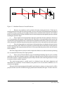
Kentech Instruments Ltd.
40kHz On-Off Pockels Cell Driver
10th. October 2001
Serial Number J00****/1
PLEASE READ THIS MANUAL CAREFULLY BEFORE USING THE PULSER.
Kentech Instruments Ltd.,
Unit 9, Hall Farm Workshops, South Moreton, Didcot, Oxon, OX11 9AG, U.K.
Tel: 01235 510 748 Fax: 01235 510 722
International tel: (44) 1235 510 748 International fax: (44)1235 510 722
E-mail [email protected]
DISCLAIMER
This equipment contains high voltage power supplies. Although the current supply capacity is
small, careless use could result in electric shock. It is assumed that this highly specialised equipment
will only be used by qualified personnel.
Kentech Instruments Ltd. accept no responsibility for any electric shock or injury arising from
use or misuse of this equipment. It is the responsibility of the user to exercise care and common sense
with this highly versatile equipment.
Kentech Instruments Ltd., Unit 9, Hall Farm Workshops, South Moreton, Didcot, Oxon, OX11 9AG, England.
10th. October 2001
2
Contents
DISCLAIMER
2
1
INTRODUCTION
4
2
SPECIFICATION
4
3
GETTING TO KNOW THE INSTRUMENT
5
4
CIRCUIT AND CIRCUIT OPERATION
6
5
PERFORMANCE
8
6
MOUNTING ADAPTER
9
7
POCKELS CELL SETUP AND ALIGNMENT
Q-SWITCHING PRECAUTIONS
ADDITION OF INDEX MATCHING FLUID TO POCKELS CELLS
ADDING THE FLUID
10
13
13
14
Figure Captions
Figure 1
Figure 2
Figure 3
Figure 4
Figure 5
Figure 6
Figure 7
Figure 8
Figure 9a
Figure 9b
Figure 10
Figure 11
Figure 12
Figure 13a.
Figure 13b.
The front panel of the power supply
The basic circuit diagram of the head
The connectors to the head
The whole system set up for chopping
The underside of the base
Rising edge
Falling edge
Overall pulse 100ns
Ringing at 31kHz
Ringing at 37.7kHz
Rise time calculation
The mounting base
Modulator Between Crossed Polarisers
Isogyre Pattern Off Centre
Isogyre Pattern Centred
5
6
7
7
7
8
8
8
8
8
8
9
11
12
12
Kentech Instruments Ltd., Unit 9, Hall Farm Workshops, South Moreton, Didcot, Oxon, OX11 9AG, England.
10th. October 2001
3
1
INTRODUCTION
This equipment is designed to apply an electric field to a crystal or crystals within a pockels cell,
for an adjustable time in the range 10 to 100ns. With suitable setting up this range can be extended
to 2ns to 1µs. The rise and fall times are of the order of 2ns.
The equipment comprises a power supply and a “head”. Within the head is a pockels cell and
a pair of switches. One switch is used to apply the electric field and one to remove it. The relative
timing of the signal to each switch determines the duration of the pulse applied to the cell.
Pockels cells change the polarisation of light by retarding waves at different rates depending
upon their relative polarisation with respect to an optical axis. The degree of retardation is dependent
on the material, the wavelength of the light to be modified, the geometry and the electric field. In most
applications one is trying to change the polarisation by 90°. This involves a relative retardation of
two orthogonal waves of λ/2. Pockels cells allow this relative retardation to be switched quickly. The
process is limited only by how fast the electric field can be set up within the crystal.
Within this manual the “OFF switch” is in fact a switch that closes and there by removes the
electric field from within the cell.
2
SPECIFICATION
Switched voltage 630 volts to 4kV
Maximum voltage change across cell
2.9kV with a 5pF cell.
Minimum pulse length, limited by rise/fall time
Maximum pulse length 1µs, but optimised for 100ns
Rise time approximately 2ns with a 10pF cell, see data.
Fall time as rise time.
Trigger input for turn on, TTL level with 50Ω termination, delay 50ns
Trigger input for turn off, TTL level with 50Ω termination, delay 40 ns
Trigger OFF can be set to be driven by the falling edge of the trigger on, slave mode, the off
delay is 45ns from this edge.
Maximum repetition rate at maximum voltage, 50kHz
Safety features
This unit can deliver around 60 watts to the head. As there is a potential fire hazard some
safety features have been built in.
Thermal
Both the head and the power supply are fitted with thermal trips.
The power supply thermal trip (70°C) is self resetting and turns off the power to the unit.
The head thermal trip (55°C) is manually reset from the front panel of the power supply.
The head is cooled with forced air. The vents should not be obstructed.
Over current detect
The current to the head is compared with that calculated from the product of the trigger rate
and the set voltage. A poor comparison results in a trip out of the
power supply this is only useful for moderately constant trigger
rates.
Overvoltage detect.
In addition to the feedback stabilisation of the voltage supplies a second back up system will
trip out the power supply if the voltage is more than 10% over the
set figure.
Kentech Instruments Ltd., Unit 9, Hall Farm Workshops, South Moreton, Didcot, Oxon, OX11 9AG, England.
10th. October 2001
4
Figure 1
3
The front panel of the power supply
GETTING TO KNOW THE INSTRUMENT
The equipment comprises a power supply and head with a connecting cable assembly having
four connectors each end.
The power supply front panel is shown in figure 1. The top row of items are overall control of
the unit. The lower two rows are one for each switch in the head and are labelled ON and OFF. They
are not quite identical and the leads should not be intermixed.
Indicators
Power
Trigger ON
LT output HT output
Trigger OFF
LT output HT output
Trigger OFF
The head should set up as a regular
pockels cell. See section 7 for some
HT
Overtemp
Overload
On channel
O/P on
Current
Off Channel
O/P on
Current
Start/Stop
Set HT
Set Trip
Trigger OFF mode, internal (slave)
and external
Connectors
Remote inhibit, Short to inhibit
Controls
Inhibit
notes on possible methods for doing this. Make sure that the airflow to the rear of the head is not
restricted and that it does not cause disturbance to other optical systems. The leads should be
connected as labelled. The voltage should be set to the anticipated setting, this will depend upon the
particular cell, wavelength and configuration in use. E.g. a KD*P longitudinal cell operating at
780nm needs around 2.5kV for quarter wave use. The actual voltage switched across the cell is
around 3/4 of the set voltage due to capacitive sharing losses, see section 4.
Kentech Instruments Ltd., Unit 9, Hall Farm Workshops, South Moreton, Didcot, Oxon, OX11 9AG, England.
10th. October 2001
5
ON HT
Rc
switch
capacitance
Cs
OFF HT
Rbal
Balance
resistor
Cell
Rc
Cc
ON switch
Cs
switch
capacitance
OFF switch
Figure 2
The basic circuit diagram of the head
The trigger mode should be selected. In external mode, two triggers are required, one for each edge.
In internal mode the rising edge of the trigger pulse will turn the unit ON and the falling edge OFF.
There is an offset so that very short optical pulses can be generated with a reasonable length trigger
pulse; see specifications.
4
CIRCUIT AND CIRCUIT OPERATION
The circuit of the head is shown schematically in figure 2. Note that although this looks
symmetrical in fact the OFF switch contains additional logic to turn both switches off simultaneously.
In normal operation the system is powered up and the HT charges the capacitance of the two
switches to the set voltage. At this stage and during the charge there is no voltage across the cell
as both sides charge up together. When the ON switch is triggered this side of the cell is brought
to zero voltage. However, in doing so the charge on the OFF switch is shared between the cell and
the OFF switch. The result is that the OFF side of the cell sees a voltage drop also. The net voltage
across the cell is therefore:Vnet = Vset {Csw/(Csw+Cc)}
Where Vnet is the net voltage change across the cell, Vset is the set voltage, Csw is the switch
capacitance of around 50pF and Cc is the cell capacitance. In this case with a customer’s cell of
around 10pF, the maximum switched voltage is around 3.0kV.
The system is designed for high repetition rate. Accordingly the charging resistors are quite
low. This results in significant current flowing in the charging resistor to attempt to recharge the
OFF switch back to the set voltage from which it has dropped slightly. Without correction the OFF
switch voltage would gradually return to the set value, giving a poor flatness to the optical
properties of the cell. To correct for this a balance resistor is placed across the cell. This is chosen
Kentech Instruments Ltd., Unit 9, Hall Farm Workshops, South Moreton, Didcot, Oxon, OX11 9AG, England.
10th. October 2001
6
such that the voltage on the OFF switch remains constant during the ON phase of the system. The
voltage on the OFF switch due to the charging current is
VOFF = Vset {Rbal/(Rbal+Rc)} : where Rbal and Rc are the balance and charge resistors respectively
Note that this just states that the ratio of the resistors is the same as the ratio of the capacitances.
5
PERFORMANCE
Figure 3
The connectors to the head
Figure 4
The whole system set up for chopping, note the polarisers are not part of the
supplied system
Figure 5
The underside of the base
Kentech Instruments Ltd., Unit 9, Hall Farm Workshops, South Moreton, Didcot, Oxon, OX11 9AG, England.
10th. October 2001
7
The unit was tested with a red laser diode and photodiode detector. The bandwidth of the
detection equipment was around 500MHz. The laser power was sufficiently low that noise levels at
the detector were a problem. In addition the laser diode showed evidence of pick up of the drive signal
to the pockels cell.
The cell was arranged for both single pass and double pass modes. Results below are for the
double pass mode which offers more sensitivity but there is an increased rise time due to the round
trip time from the cell to the end mirror and back, this added around 300ps to the response.
The results are shown in figures 6 through 10. In all cases the top trace is that corrected by
subtraction of the noise, i.e. the top equals the middle trace less the bottom trace.
Figure 6
Rising edge
Figure 7
Falling edge
Figure 9a Ringing at 31kHz
Figure 8
Overall pulse 100ns
Figure 9b Ringing at 37.7kHz
Rising Edge
1
Light intensity, arbitrary units
0.8
0.6
Rise ime 2.05ns
Round trip time to mirror 0.3ns
corrected cell risetime 1.75ns
0.4
0.2
0
-0.2
-4
-2
0
2
4
6
8
ns
Figure 10 Rise time calculation
Kentech Instruments Ltd., Unit 9, Hall Farm Workshops, South Moreton, Didcot, Oxon, OX11 9AG, England.
10th. October 2001
8
6
MOUNTING ADAPTER
Figure 11 indicates the layout of holes for the mounting adapter which is fitted to the bottom of
the housing. The outer corner holes are available to the user to mount the cell.
The optical axis passes above the centre line of this plate at a height of 35.85 mm above the base
of the plate.
3.5
76
13
4 x ø3
50
76
50
69
69
3.5
9.5
Mounting adapter
Dimensions in mm
Figure 11 The mounting base
Kentech Instruments Ltd., Unit 9, Hall Farm Workshops, South Moreton, Didcot, Oxon, OX11 9AG, England.
10th. October 2001
9
NOTES ON THE SETTING UP AND ALIGNMENT OF POCKELS CELLS. BASED
UPON A FAST PULSE TECHNOLOGY USER MANUAL OF 1991.
7
POCKELS CELL SETUP AND ALIGNMENT
This procedure is applicable to all modulators and Q-switches both transverse and longitudinal
mode, fabricated with KDP, KD*P, ADP, AD*P and similar single axis crystals.
FastPulse Technology type Q-switches are supplied with a marker on one of the stainless steel
aperture plates or the outer housing to indicate the polarisation plane of the incoming beam. In some
models, the connector or terminals serve as the marker. The input plane of polarisation must be
aligned with the marker (or rotated 90° from it) for correct operation. If the marker is missing, then
the appropriate directions must be determined by viewing the side of the crystal inside of the device
through the clear aperture in a bright light. All crystals have a straight line marked on the barrel of
crystal (the crystal is cylindrical) . The input plane of polarisation must be parallel to or perpendicular
to the line on the crystal.
CAUTION: Protective laser goggles should be worn during the following alignment procedures.
It is strongly recommended that initial alignment of all pockels cells be done with a low power
(0.5 to 2 mW) HeNe laser (or similar) to assist in visualizing beam position. We do not recommend
attempting this alignment procedure with an IR laser unless the power can be throttled to 1 or 2 mW
and an IR viewer is available. Great care must be taken to insure that the laser beam does not impinge
on the external aperture stops or the crystal electrodes. At higher, operating power levels, it is possible
to damage the device if the beam strikes the internal electrodes thereby causing thermal damage.
Unless there are strict restraints on space and positioning devices, the device should be mounted
in a gimbal that provides accurate and stable pitch and azimuth adjustments. Some means for
obtaining horizontal and vertical translation is usually necessary to centre the device on the input
laser beam.
If the Pockels cell is being used in a laser cavity, it is recommended that the alignment be done
with a HeNe laser having its beam coaxial with the laser rod. This coaxial condition should be
confirmed by operating the laser with the HeNe to insure that the beams are indeed coaxial and the
HeNe beam centred. If this cannot be done conveniently, then the HeNe beam should be retroreflected off the nearest laser rod surface back onto itself. The Q- switch can then be placed in the
optical train.
It is essential that the laser beam pass through the Pockels cell entrance and exit apertures without
vignetting. The beam should be centred in both apertures with at least 0.5 mm clearance all around.
The following procedure has been shown to be most reliable for obtaining optimum alignment.
The object is to centre the laser beam in the device apertures and then generate an optical pattern
which accurately locates the optical axis of the crystal with respect to the laser beam.
The procedure will probably require several adjustments of pitch, azimuth and translation to
optimise the alignment but it will provide positive and visual confirmation of the alignment. The
basic alignment configuration is shown in Figure 12.
Kentech Instruments Ltd., Unit 9, Hall Farm Workshops, South Moreton, Didcot, Oxon, OX11 9AG, England.
10th. October 2001
10
Laser
Pockels
cell
Tape
Polariser
Analyser
card showing Isogyre
pattern
Figure 12 Modulator Between Crossed Polarisers
1.
Remove any polarisers used to polarise the beam entering the device. If the laser is
already polarised it does not effect this procedure, however, the plane of polarisation must be aligned
(eyeball accuracy is usually good enough) with the marks or terminals on the Pockels cell. Position
the device in the HeNe laser beam so that the beam is centred and passes through the apertures without
touching the aperture edges.
2
Place a light coloured matt finish card in the path of the beam at a distance of between
1 to 2 feet from the exit aperture of the Pockels cell. If the device is located within a laser cavity, the
card should be placed against the laser rod holder and a small hole made in the card to locate the centre
of the rod aperture. Mark the beam location on the card with a circle or dot and leave the card in place.
3
Place the input polariser in the beam with its polarising axis aligned to the mark on the
Pockels cell aperture plate. If the laser rod produces a polarized beam (as with a ruby rod) the polariser
must be aligned to the rod polarisation direction. It is assumed that the polariser does not deviate the
beam angularly.
Place the output polariser (analyser) at the output side of the device and insure that its polarising
axis is rotated 90° from that of the input polariser.
4.
Place a strip of frosted adhesive tape (Scotch Magic Mending Tape No. 810 or similar
material) over the device entrance aperture. Gently press the tape in place but do not allow it to touch
the window surface. A lightly frosted glass plate will provide the same scattering but must be nearly
in contact with the entrance aperture.
The actual measurement is usually made in a darkened room after basic alignment and
adjustments are completed. In most instances, the pattern to be viewed will be difficult to see in
normal room lighting.
When the HeNe beam propagates through the optical train, a pattern, or some part of it, will be
projected on the card. This is called an isogyre pattern and is illustrated in Figure 13a and 13b below.
Kentech Instruments Ltd., Unit 9, Hall Farm Workshops, South Moreton, Didcot, Oxon, OX11 9AG, England.
10th. October 2001
11
laser beam
Figure 13a. Isogyre Pattern Off Centre
Figure 13b. Isogyre Pattern Centred
If the optic axis of the crystal is not parallel to the path of the laser beam, the isogyre pattern will
be off-centre and the device must be moved in pitch and azimuth. When the isogyre is centred over
the circle or dot or hole in the card this indicates that the device is well aligned.
After making any positional adjustments, the beam position relative to the device aperture stops
must be confirmed. The beam must still pass through both apertures without vignetting and with
adequate clearance. If it does not, employ horizontal and vertical translation until clearance is
confirmed. If the figure is not in the form of a cross, then the polarisers are not rotationally aligned
to the faceplate mark or at 90° to each other.
Once the cross of the isogyre is centred, the polarisers can be rotated slightly to maximize the
darkness of the centre of the cross. After this is done, the device is not only aligned with the laser
beam, it is also nulled with respect to the crossed polarisers for best contrast ratio and it is ready for
operation.
The extra polariser, if one was used, may be removed.
3.0
OPERATION
3.1
Cautionary Note:
Application of DC voltage to some Pockels cell Q-switches and light modulators for long
periods of time may result in permanent damage to the electro-optic crystal(s).
Devices fabricated from KDP, KD*P, ADP and AD*P, in the presence of continuous (DC) high
electric fields, are subject to an effect that is not well understood but is apparently electrolytic in
nature. With long term application of high voltage, the polished optical surfaces become fogged and
etched. All crystal surfaces, including those under the conductive electrodes can be similarly
effected. This may result in discontinuities between the crystal and electrode conductors. Application
Kentech Instruments Ltd., Unit 9, Hall Farm Workshops, South Moreton, Didcot, Oxon, OX11 9AG, England.
10th. October 2001
12
of AC electric fields, even those with a net DC value, appear to minimize the effect and extend
lifetimes dramatically.
The effect is independent of the electrode materials used and has been documented for gold,
indium, silver and transparent conductive oxide electrode materials. One manufacturer reports that
a sustained voltage of 50 volts will eventually have an effect on the crystal. Use of inert index
matching fluids does not mitigate the damage. The effect appears with or without the use of fluid.
We recommend that DC voltage not be applied to a Pockels cell when the laser system in which
it is employed is not actively in use. When the system is in a stand-by condition, care must be taken
to turn off the DC voltage to the Pockels cell. When this procedure is followed, operational lifetimes
of more than 5 years is not unusual and where this “voltage off” safeguard has been observed, many
Fastpulse/Lasermetrics Q-switches have been in active use for more than 15 years
Q-SWITCHING PRECAUTIONS
KD*P (and many other electro-optic crystals) exhibit a piezoelectric effect that can have an
adverse effect when Q-switching. The effect can be neutralized by appropriate timing of the electrical
pulse to the Q-switch.
The piezoelectric effect becomes apparent when a crystal such as KD*P is excited by a fast rise
time electrical pulse. Physically, the crystal is excited into mechanical oscillation; a contraction and
extension that effects the indices of refraction. In the case of quarter wave switching, DC high voltage
is applied to the crystal to prevent lasing; the voltage is then switched to zero volts to allow the Qswitched optical pulse to be generated. The piezoelectric effect, in the form of a damped oscillation
or ringing, appears some time after the voltage is switched to zero level. The actual time at which the
ringing occurs and the frequency of the ringing is dependent on the physical dimensions of the crystal.
The larger the crystal, the lower the frequency and the longer the time period before ringing occurs.
The effect of piezoelectric ringing on the chopped laser output is the generation of multiple
pulses. If the incident beam is CW then multiple pulses may occur. Note that if the electrical drive
pulse is very short it will contain very little energy at the acoustic frequencies and consequently there
will be little coupling to the piezzo electric modes. This is not true for Q switching where a step
waveform is used and the low frequency components are significant.
Note however, that the DC and Pulsed voltage for half wave operation may be different as the
DC voltage can induce strain in the crystal that changes the refractive indices. If good transmission
is not obtainable in pulsed mode then it may be necessary to modify the applied pulsed voltage.
ADDITION OF INDEX MATCHING FLUID TO POCKELS CELLS
Many Pockels cell Q-switches and electro-optic light modulators produced by FastPulse are
equipped with a sealed housing for index matching fluid. In this type of device, the housing contains
a filler hole that is sealed by compression of a viton O-Ring with a screw. In most housings, windows
may be removed for replacement or to rapidly drain the fluid. The housing may then be resealed by
proper compression of the viton O-Ring beneath the window. Removal of the protective windows
is not recommended unless the user is familiar with handling water soluble crystals and the operation
can be performed in a dust-free and low relative humidity (<50%) atmosphere.
It is recommended that the Q-switch or modulator be returned to FastPulse for any operation that
involves exposure of the cell interior. In cases where this is not feasible or where fluid leakage has
occurred slowly over a long period, follow the filling procedure detailed below.
Kentech Instruments Ltd., Unit 9, Hall Farm Workshops, South Moreton, Didcot, Oxon, OX11 9AG, England.
10th. October 2001
13
If it becomes necessary to add index matching fluid to the Pockels cell, a hypodermic syringe
must be employed and the correct fluid type must be used. A replacement kit containing fluid, syringe,
needle, and filter assembly is available from FastPulse at nominal cost.
Three kits are available: IMFK-104, IMFK-43 and IMFK-D. Most standard production
modulators and Q-switches utilize the type 104 fluid which is included with the IMFK-104 kit. The
filters and filter assemblies for the 43 and 104 fluids are identical.
Another fluid in use is Decalin This fluid requires special filter elements and assemblies because
it will chemically attack many plastics. Specify IMFK-D for the Decalin refill kit.
Decalin cannot be used in devices that were not originally designed for its use. If in doubt as to
which index matching fluid has been used in a particular device, contact FastPulse for details.
ADDING THE FLUID
A filter assembly consists of two cylindrical parts which may be unscrewed to insert the filter
element. This should be done in a dry, dust-free environment. Before placing the filter assembly on
the hypodermic syringe, the needle should be attached to the syringe and the syringe filled with index
matching fluid. Then remove the needle, attach the filter assembly to the syringe and the needle onto
the filter assembly.
Press the syringe plunger and force approximately 1 cm3 of fluid back into the fluid container.
This will insure that any dust trapped on the output side of the filter, its housing or in the needle will
not be injected into the Pockels cell. Always recap the fluid container to prevent evaporation and entry
of dust particles.
The following precautions must be exercised when filling the sealed housings:
1
The interior of the sealed housing and the injected fluid must be kept free of
particulate matter. A 0.22 µm Millipore filter attachment or equivalent is recommended
for use with the hypodermic syringe.
2
The filler hole area and screw head must be clean before the filler screw is removed.
The entire operation should be performed in a dust free area.
3
When the hypodermic syringe is inserted in the filler hole, extreme care must be
taken to avoid cocking the syringe and striking the crystal face. Any contact between
the needle point and the crystal surface will cause a severe dig or scratch. Also avoid
resting the needle point on the side of the crystal.
4
The filler screw and O-Ring must be cleaned of articulate matter before resealing.
Excess index matching fluid that seeps out when the filler screw is tightened may be
removed with a cloth or tissue.
Kentech Instruments Ltd., Unit 9, Hall Farm Workshops, South Moreton, Didcot, Oxon, OX11 9AG, England.
10th. October 2001
14
NOTES:
A
An air bubble is left in all fluid-filled cells for pressure relief. The size of the bubble
must be restricted so that it will not obstruct the optical path. Most modulators may be operated at
an incline of up to 70 degrees with the horizontal. Such an incline is considerably less for 5/8 and 3/
4 inch aperture units. When vertical operation is required, a “dry” modulator may be necessary.
B
Never return index matching fluid to its original container without injecting through the
filter. Returning it without filtering may contaminate the remaining fluid with particulate matter -
REFERENCE
R. Goldstein, Electro-Optic Devices in Review”, Lasers & Applications, April, 1986
Kentech Instruments Ltd., Unit 9, Hall Farm Workshops, South Moreton, Didcot, Oxon, OX11 9AG, England.
10th. October 2001
15
Kentech Instruments Ltd., Unit 9, Hall Farm Workshops, South Moreton, Didcot, Oxon, OX11 9AG, England.
10th. October 2001
16