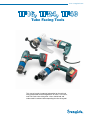
1
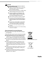
www.swagelok.com Tube Facing Tools This manual contains important information for the safe and effective operation of the Swagelok® TF16 series, TF24 series, and TF40 series tube facing tools. Users should read and understand its contents before operating the tube facing tool. 2 Tube Facing Tool User’s Manual Tube Facing Tool User’s Manual Contents Safety . . . . . . . . . . . . . . . . . . . . . . . . . . . . . 5 Safety Summary . . . . . . . . . . . . . . . . . . . . . . 5 Environmental Protection/Disposal . . . . . . . . . . . . 7 Product Information . . . . . . . . . . . . . . . . . . . . . 8 TF16 Series . . . . . . . . . . . . . . . . . . . . . . . . . 8 TF24 Series . . . . . . . . . . . . . . . . . . . . . . . . . 9 TF40 Series . . . . . . . . . . . . . . . . . . . . . . . . 10 Accessories . . . . . . . . . . . . . . . . . . . . . . . . 11 Specifications . . . . . . . . . . . . . . . . . . . . . . . . 12 Application range . . . . . . . . . . . . . . . . . . . . . 12 Tube materials . . . . . . . . . . . . . . . . . . . . . . . 12 Technical data . . . . . . . . . . . . . . . . . . . . . . . 12 Setup . . . . . . . . . . . . . . . . . . . . . . . . . . . . . 13 Description . . . . . . . . . . . . . . . . . . . . . . . . . 13 Unpacking the Tube Facing Tool . . . . . . . . . . . . . 14 Installation of the Bench Mount Bracket . . . . . . . . . 14 Installation of the Cutting Insert and the Tool Holder . . . 15 Installing the Collet Set . . . . . . . . . . . . . . . . . . 16 Removing the Collet Set . . . . . . . . . . . . . . . . . . 17 Installing the Collet Set Adapter for TF40 Series . . . . . 18 Operation . . . . . . . . . . . . . . . . . . . . . . . . . . . 19 Clamping the tube . . . . . . . . . . . . . . . . . . . . . 19 Removing the Tube . . . . . . . . . . . . . . . . . . . . 19 Tool Speed Range . . . . . . . . . . . . . . . . . . . . . 20 Facing the Tube . . . . . . . . . . . . . . . . . . . . . . 22 Operating in Space-Restricted Environments . . . . . . . 24 Maintenance . . . . . . . . . . . . . . . . . . . . . . . . . 25 Troubleshooting . . . . . . . . . . . . . . . . . . . . . . . 26 3 4 Tube Facing Tool User’s Manual Tube Facing Tool User’s Manual Safety Safety Summary Read the entire safety information section and Tube Facing Tool User’s Manual before using this product. Failure to do so can result in serious injury or death. Signal Words and Safety Alert Symbols Used in this Manual WARNINGStatements that indicate a hazardous situation which, if not avoided, could result in death or serious injury. CAUTIONStatements that indicate a hazardous situation which, if not avoided, could result in minor or moderate injury. NOTICE Statements that indicate a hazardous situation which, if not avoided, could result in damage to the equipment or other property. Safety alert symbol indicating a potential personal injury hazard. Sinjury afety alert symbol indicating a potential for personal from electrical shock. Safety Information WARNING Danger of death by electric shock ■If the power cord is damaged, electrically live parts may cause death if touched directly. ■ Do not allow the tool to run unattended. ■The tool should be connected to a ground fault current interrupt (GFCI) protected outlet. ■Read through the operating instructions and safety information completely before using the rechargeable battery and charger of the TF16 series, TF24 series, or TF40 series cordless models. ■Work on electrical equipment must be done by a qualified electrician. ■Switch off the tool, allow it to run until it stops rotating and remove the plug from the power outlet or take out the rechargeable battery before changing tooling, maintaining, or transporting the tool. 5 6 Tube Facing Tool User’s Manual WARNING Danger of eyes being injured by hot and sharp-edged metal chips. Eye protection must be worn while operating or working near the equipment. WARNING Keep dry. Equipment and components are not waterproof. Do not use electric tools and rechargeable batteries in a damp or wet environment. WARNING Fire or Explosion Do not use in close proximity to flammable liquids or gases. WARNING Danger of being injured by sharp cutting edges ■Do not touch the cutting insert while the tool is operating. ■ Wear safety gloves. ■Do not remove chips or tubing from the work area when the tube facing tool is still running and the tool is not yet at rest. ■Wear safety gloves to remove chips. Remove long and bent chips with needle-nose pliers. WARNING Danger of being injured by rotating parts. Keep hands, loose clothing, and long hair away from rotating and moving parts. Tube Facing Tool User’s Manual WARNING Observe the following safety measures in order to protect against risk of injury. ■Inspect the tube facing tool daily for visible signs of damage or defects. Have any damage or defects repaired immediately. ■Always ensure that the machine is in good working order and comply with these notes on safety. ■Use only the tube ODs, wall thicknesses and materials specified in these instructions. Other materials should be used only after consulting your authorized Swagelok representative. ■ Check that the work piece is correctly clamped. ■Do not carry the tube facing tool by the power cord and do not use the cord to pull out the plug. Protect the cord from heat, oil and sharp edges (chips). ■Ensure that the viewing window is closed (TF24 and TF40 series) or the guard is in place (TF16 series) before and during the facing of tubing. ■Always work with sharp cutting tools to reduce vibrations. ■Turn the tool off and let it run until it stops rotating when work is complete. Environmental Protection/Disposal ■ Dispose of chips and used gear lubricant oil according to local regulations. Electric tools and accessories contain a large share of valuable raw and synthetic materials, which can be recycled. Therefore: ■ Electrical (electronic) devices that are marked with the symbol in Fig. 1, may not be disposed of with household waste in accordance with European Union (EU) regulations. ■ By using local return and collection systems, you contribute to the reuse, recycling and utilization of electrical (electronic) devices. ■ Electrical (electronic) used devices contain parts, which must be handled selectively according to EU regulations. Separate collection and selective treatment is the basis for environment-friendly disposal and the protection of human health. Fig. 1 RL 2002/96/EC Symbol ■ Batteries that are marked with the symbol in Fig. 2 may not be disposed of with household garbage according to EU directive 91/157/EEA. ■ In batteries containing harmful substances, the chemical sign for the heavy metal contained is indicated below the garbage can: Cd = Cadmium Fig. 2 Cd Symbol 7 8 Tube Facing Tool User’s Manual Product Information TF16 Series 4 5 3 2 6 1 7 8 Fig 3 TF16 Series Corded Model 1 Collet housing5 ON-OFF lock 2 Viewing window6 ON-OFF switch 3 Feed dial with scale divisions 7 Bench mount bracket (optional) 4 Motor 8 Tube clamp 1 2 4 3 7 6 5 Fig 4 TF16 Series Cordless Model 1 Collet housing5 Rechargeable battery 2 Viewing window6 ON-OFF switch/speed control 3 Feed dial with scale divisions 4 Motor 7 Tube clamp Tube Facing Tool User’s Manual TF24 Series 5 6 9 3 4 7 2 8 1 Fig 5 TF24 Series Corded Model 1 Collet lock6 ON-OFF lock 2 Collet housing7 ON-OFF switch 3 Viewing window8 Bench mount bracket (optional) 4 Feed dial with scale divisions9 Tube clamp 5 Motor 3 4 5 8 2 1 7 6 Fig 6 TF24 Series Cordless Model 1 Collet lock6 Rechargeable battery 2 Collet housing7 ON-OFF switch/speed control 3 Viewing window8 Tube clamp 4 Feed dial with scale divisions 5 Motor 9 10 Tube Facing Tool User’s Manual TF40 Series 3 12 11 4 5 6 1 7 2 9 10 8 Fig 7 TF40 Series Corded Model 1 Tube clamp7 ON-OFF switch 2 Collet housing8 Bench mount bracket (removable) 3 Viewing window9 Collet locks 4 Feed dial with scale divisions 10 Tool holder and cutting insert 5 Motor11 High/low motor setting dial 6 ON-OFF lock12 Speed adjustment dial 3 4 5 8 1 2 7 9 6 Fig 8 TF40 Series Cordless Model 1 Tube clamp6 Rechargeable battery 2 Collet housing7 ON-OFF switch/speed control 3 Viewing window8 Collet locks 4 Feed dial with scale divisions 9 Tool holder and cutting insert 5 Motor Tube Facing Tool User’s Manual Accessories TF Series Cutting Insert The cutting insert is supplied and can be used with all TF series tool holders. Cutting Tool Holder for Beveling and Squaring Fig 9 Cutting Insert An adjustable tool holder is included with a Torx screw. Additional tool holders with different bevel angles are available. Collet Set Adapter This adapter is supplied as standard with the TF40 series. Using this adapter, the TF24 series collet sets can be used with the TF40 series, which extends the processing range to a minimum of 0.250 inch or 6 mm. Included: ■ 1 collet set adapter ■ 1 clamping screw Fig 10 Collet Set Adapter Stainless Steel Collet Set These are used for deformation-free clamping of tubing. They ensure precise mounting of tubing or Micro-Fit® fittings and a quick change of collet sets without tools. For use on all tubing materials with an OD from 0.125 to 2.500 in. or 3 mm to 63.5 mm. See Tube Facing Tools, MS-02-426, for additional information on the optional accessories. Fig 11 Stainless Steel Collet Set 11 12 Tube Facing Tool User’s Manual Specifications Application Range Series TF16 Tube OD min. to max. range TF24 0.118 to 1.00 in. (3.0 to 25.4 mm) Wall thickness max. 0.118 in. (3.0 mm) TF40 0.118 to 1.50 in. (3.0 to 38.1 mm) 0.250 ➀ to 2.50 in. (6.35➀ to 63.5 mm) 0.118 (3.0 mm) 0.118 in. (3.0 mm) ➀ Requires optional collet set adapter. Tube Materials ■ Stainless steel ■ Nickel alloys — Alloy 600, Alloy 625, Alloy 825 ■ Aluminum Contact your authorized Swagelok representative for information on additional materials. Technical data Series TF16 TF16 Cordless TF24 TF24 Cordless TF40 TF40 Cordless Dimensions, in. (mm) 15.4 W, 7.87 H, 2.76 D (390 W, 200 H, 70 D) 10.3 W, 10.0 H, 3.15 D (261 W, 255 H, 80 D) 15.8 W, 13.8 H, 6.30 D (400 W, 350 H, 160 D) 10.8 W, 10.0 H, 3.54 D (275 W, 255 H, 90 D) 19.7 W, 11.8 H, 6.69 D (500 W, 300 H, 170 D) 10.2 W, 11.8 H, 12.6 D (260 W, 300 H, 320 D) Weight Without Accessories, lb (kg) 9.13 (4.14) 6.35 (2.88) 10.4 (4.7) 7.58 (3.44) 14.6 (6.60) 11.5 (5.23) Input voltage Single-phase alternating current, protection class II 110 V 50/60 Hz 230 V 50/60 Hz Power, W 1100 – 1100 – 1100 – Voltage Rechargeable Battery, V – 18 – 18 – 18 Speed r/min 145 to 380 0 to 400 145 to 380 0 to 400 Speed 1: 9 to 52 Speed 2: 27 to 153 Speed 1: 0 to 24 Speed 2: 0 to 83 Sound Level (EN 23741), dB approx. 78 Vibration Level (EN 50144), m/s² < 2.5 < 2.5 < 2.5 < 2.5 < 2.5 < 2.5 Service Current Requirement A 10 minimum – 10 minimum – 10 minimum – Tube Facing Tool User’s Manual Setup Description The tube facing tools are designed for facing and preparing tube ends or Micro-Fit fittings for welding in conformance with industry standards. They have the following features: ■ A cutting tool with multiple cutting edges. Only one cutting tool is necessary for different tube wall thicknesses (up to 0.118 in./3 mm) and different tube materials (exclusively ferrous materials). ■ A cordless model with: ■ A robust, removable battery that ■ is lithium-ion for extended operation time ■ has a charge level indicator ■ High performance and small size ■ No memory effect for the battery ■ Single-cell monitoring in the battery pack ■Electronic overload protection with an integrated temperature monitor ■Air-cooled technology for short charging times and a long service life ■ A corded model with: ■A speed-controlled electric motor with speed stabilization ■Restart protection to prevent the machine from starting in an uncontrolled way after it has been reconnected to the electrical power or after a power failure ■ A quick change system for collet sets ■ A feed dial with scale divisions: ■ Total travel: 0.394 in. (10 mm) ■ Travel per rotation: 0.354 in. (9 mm) ■ Per graduation mark: 0.004 in. (0.1 mm) ■ A viewing window that provides protection. 13 14 Tube Facing Tool User’s Manual Unpacking the Tube Facing Tool Shipping Case Contents ■ 1 Tube facing tool ■ 2 Rechargeable batteries, 1 battery charger (for cordless versions only) ■ 1 Replacement breakaway nut ■ 1 Tube clamp (TF24 series only) ■ 1 Bench mount bracket (TF40 series only) ■ 1 Collet set adapter (TF40 series only) ■ 1 Tool holder with 1 cutting insert ■ 1 Tool set (4 mm T-handle hex key, 3 mm hex key, T15 Torx driver) ■ 1 Set of keys (2) for shipping case (TF16 and TF24 series only) ■ 1 User manual Report any missing or damaged parts to your authorized Swagelok sales and service representative immediately. Installation of the Bench Mount Bracket If needed, attach the bench mount bracket to the tube facing tool by tightening the screw with the provided 4.0 mm hex key. Tube Facing Tool User’s Manual 15 Installation of the Cutting Insert and the Tool Holder CAUTION Do not touch the sharp cutting edges while mounting the multifunctional tool. Wear protective gloves. Cutting Insert Attach the cutting insert to the tool holder with the curved side of the insert away from the tool holder. Use the included T15 Torx driver to tighten the screw. Tool Holder Fig 12 Installing the Cutting Insert Select a tool holder based on the tubing size. Possible Application Bevel Angle TF16 TF24 TF40 Tool Holder Style Squaring Beveling [°] Standard x – – 0.118 to 1.00 (3.0 to 25.4) 0.118 to 2.50 (3.0 to 63.5) 0.118 to 2.50 (3.0 to 63.5) Optional x – – 0.500 to 1.00 (12.7 to 25.4) 0.500 to 2.50 (12.7 to 63.5) 0.500 to 2.50 (12.7 to 63.5) Optional x – – – 0.118 - 0.835 (3.0 to 21.2) 0.250 - 0.835 (6.35 to 21.2) Optional – x 30° 1.00 (25.4) max. 1.378 (35.0) max. 2.374 (59.3) max. Optional – x 35° 1.00 (25.4) max. 1.339 (34.0) max. 2.335 (60.3) max Tube OD, inch (mm) Contact your authorized Swagelok sales and service representative for information on optional tool holders. WARNING Switch off the tool and remove the plug from the power outlet or take out the removable battery before changing tooling, performing maintenance, or transporting the tool. 1. Install the tool holder into the tube facing tool lining up the hole on the tool holder with the screw hole in the center of the tube facing tool. Fig 13 Installing the Tool Holder, TF16 and TF24 series 16 Tube Facing Tool User’s Manual 2. TF40 series only: install the tool holder in one of the six screw locations according to the type of application. The tool mounting plate of the TF40 offers different tool holder mounting options, according to type of application: ■ Facing of 1/4 to 1/2 in. (6.35 to 12.7 mm) ■ Facing of 1/2 to 2 1/2 in. (12.7 to 63.5 mm) ■ Beveling, dimension range as per bevel tool Screw location 3. Tighten the screw of the tool holder with the included 4.0 mm T-handle hex key. Installing the Collet Set 1. Select the correct collet set according to the tube OD. See Installing the Collet Set Adapter if necessary. 2. Unscrew the collet lock: TF16 series: Turn the collet lock counter clockwise until the end is flush with the inside of the collet housing. Fig 14 Installing the Tool Holder, TF40 series TF24 and TF40 series: Turn the tube clamp counter clockwise until the end is flush with the inside of the collet housing. Then turn the collet lock(s) counter clockwise until the end(s) are flush with the inside of the collet housing. Tube clamp Tube clamp Collet housing Collet housing Fig 15 TF16 Series, Step 2 Collet lock Fig 16 TF24 Series, Step 2 Collet housing Tube clamp Collet lock Fig 17 TF40 Series, Step 2 Tube Facing Tool User’s Manual 17 3. Insert the collet set into the body by pressing the collet halves together and setting into the collet housing. Note: TF24 and TF40 series, line up the unthreaded set point on the collet set with the red dot on the collet housing. (The collet lock will thread into the threaded hold on the other half of the collet set.) Note: The collet set will lock into place when installed correctly. If the collet set is not locked, turn the collet set until it locks. Fig 18 Step 3 4. TF16 series: Secure the collet set by turning the tube clamp clockwise until it stops. TF24 and TF40 series: Secure the collet set by turning the collet lock(s) clockwise one turn. Turn the tube clamp clockwise until it stops. Tube clamp Tube clamp Opening Tube clamp Opening Opening Fig 19 TF16 Series, Step 4 Collet lock Fig 21 TF40 Series, Step 4 Fig 20 TF24 Series, Step 4 Removing the Collet Set To remove a collet set, loosen the collet lock(s) and tube clamp until the collet set can be removed by pressing the collet set halves together through the opening in the collet housing. 18 Tube Facing Tool User’s Manual Installing the Collet Set Adapter for TF40 Series NOTICE Using the collet set adapter could interfere with the tool holder and damage the tool. Check the tool holder prior to installing the adapter. 1. Install when cutting tube with an outer diameter of 0.250 to 1.5 in. or 6 to 35 mm. 2. Turn the tube clamp until the end is flush with the inside of the collet housing. 3. Turn the collet locks until the ends are flush with the inside of the collet housing. Collet locks Tube clamp Fig 22 TF40 series 4. Install the collet set adapter into the tube facing tool. The opening in the adapter should be flush with the opening in the tool. Adapter Opening Fig 23 Inserting the Collet Set Adapter 5. Secure the collet set adapter by turning the collet locks. 6. See Installing the Collet Set to install the collet set. Tube Facing Tool User’s Manual Operation The tool should only be operated using a ground fault current interrupt (GFCI) protected outlet. Clamping the Tube CAUTION Support long pieces of tubing with suitable fixtures. Injury from tilting tool and/or tilting tubing could result. CAUTION Verify that the tube facing tool is not rotating before clamping the tube. NOTICE The cutting tool can be damaged by incorrect set up. Before clamping the tube, verify there is space between the cutting insert and the tube. 1. Insert the tube in the collet set of the tube facing tool. 2. Secure the tube by turning the tube clamp clockwise until it stops. Note: Clamp the tube squarely, ensuring that the tube and the face of the collet set are perpendicular to each other. The tube end will not have a right angle cut when not clamped properly. Fig 24 Clamping the Tube Removing the Tube To remove the tube from the facing tool, rotate the tube clamp counterclockwise until the tube is loose enough to remove. 19 Tube Facing Tool User’s Manual 20 Tool Speed Range Selecting the Speed Range Speed range, rpm Level 1 Level 2 Series Turtle Rabbit TF16 145 to 380 (disabled) TF16 Cordless 0 to 400 (disabled) TF24 145 to 380 (disabled) TF24 Cordless 0 to 400 (disabled) TF40 9 to 52 27 to 153 TF40 Cordless 0 to 24 0 to 83 TF40 Series Only There are 2 speed levels. It is recommended that you work exclusively at the Level 1. Increase or decrease the speed by turning the high/low motor setting dial. Speed Level Speed, rpm Level 1 9 to 52 Level 1 Turtle Level 2 Rabbit Fig 25 High/low Motor Setting Dial Turtle Level 2 27 to 153 Rabbit Adjusting the Speed: Corded Models Set the speed by turning the speed dial. TF16 TF24 TF40 Level Tube OD inch (mm) Level Tube OD inch (mm) Level Tube OD inch (mm) C 0.125 (3.18) C 0.125 (3.18) G 0.250 (6.35) B 0.250 (6.35) B 0.250 (6.35) D 1.500 (38.1) A 0.500 (12.70) A 0.500 (12.7) C 2.000 (50.8) A 1.000 (25.4) A 1.500 (38.1) B 2.500 (63.5) Fig 26 Speed Adjustment Dial Tube Facing Tool User’s Manual Adjusting the Speed: Cordless Models The speed level is factory set in cordless models. See the table on the previous page for speed range information. The speed range can be adjusted with the ON-OFF switch/speed control. ■ Depress the ON-OFF switch/speed control to increase the speed. ■ Gradually release the pressure on the ON-OFF switch/speed control to decrease the speed. ON-OFF switch/ speed control Fig 27 ON-OFF Switch/Speed Control 21 22 Tube Facing Tool User’s Manual Facing the Tube WARNING Allow the machine to run until it stops rotating after cutting tube to avoid injury. WARNING Do not touch the tool holder or cutting insert while the tool is in operation. WARNING Only operate the tool with a clamped tube (all series) and a closed viewing window (TF24 and TF40 series). WARNING Eye protection must be worn while operating or working near the equipment. WARNING Keep hands, loose clothing, and long hair away from rotating and moving parts. WARNING Wear safety gloves to remove chips. Remove long and bent chips with needle-nose pliers or a similar tool. NOTICE Excessive feed of the cutting insert into the tube can damage the cutting tool or cause the tool to overheat. NOTICE Verify there is space between the cutting tool and the tube before clamping the tube to prevent damage to the cutting tool. The cutting tool can be damaged by a tube not cut at a right angle. NOTICE If speed is reduced too quickly, the tool may “dig” into the tube, causing damage to the tube face and the tool, and may cause the tool to stop. Reduce the feed rate of the cutting insert and the tool speed gradually. Tube Facing Tool User’s Manual NOTICE Verify the motor is in drill mode if the motor is equipped with a hammer mode. Operating the tool in hammer mode will cause damage to the tool and the tube. Turning “On” Corded Models Fig 28 Speed Adjustment Dial 1. TF24 and TF40 series: Check that the viewing window is closed, close if necessary. 2. Set the desired speed via the speed adjustment dial. 3. Activate the ON-OFF switch. Note: If the tool vibrates after starting, the cutting speed is too high. Reduce the speed according to Adjusting the Speed. Turning “On” Cordless Models 1. TF24 and TF40 series: Check that the viewing window is closed, close if necessary. 2. Attach the rechargeable battery. 3. Activate the ON-OFF switch/speed regulator. Note: If the tool vibrates after starting, the cutting speed is too high. Reduce the speed according to Adjusting the Speed. Facing the Tube ■ Each division on the feed dial with scale adjustments equals an advancement of 0.004 in. (0.1 mm). ■ It is recommended not to exceed a clamp thickness of 0.002 in. (0.05 mm) with chip removal. Excessive feed levels will reduce the speed or stop the machine. 1. Slowly advance the cutting insert until it is in contact with the tube. 2. Continue advancing the cutting insert until the desired result is achieved. Note: To achieve the optimum squareness and finish, the tool should be allowed to rotate for 2 to 3 revolutions without further advancement of the cutting insert. 3. Release the ON-OFF switch. 4. Remove the tube by turning the tube clamp counter clockwise until it stops. Fig 29 Attaching the Battery 23 24 Tube Facing Tool User’s Manual Operating in Space-Restricted Environments To make operation easier, the position of the machine with respect to the tube can be changed as follows: Change Position of Motor 1. Remove the set screw on the back of the tool body. 2. Rotate motor to desired position. 3. Reinstall and tighten the set screw using the provided 3 mm hex key. Set screw Fig 30 Drive Position Set Screw Change Position of Body (TF40 Series Cordless Only) 1. Remove the set screw on the underside of the tool. 2. Rotate body in 90° increments until in the desired position. Pay attention to the countersinks in the tool. 3. Reinstall and tighten the set screw using the provided 3 mm hex key. Set screw Fig 31 Body Position Set Screw Tube Facing Tool User’s Manual Maintenance WARNING Switch off the tool and remove the plug from the power outlet or take out the removable battery before changing tooling, performing maintenance, or transporting the tool. When cleaning the tube facing tool, clear the collet set and tool body of debris and dirt. When changing the cutting insert, clean the tool holder and inspect it for damage. Fig 32 Loosening the Set Screw Breakaway Nut Replacement Note: The ordering number for a replacement breakaway nut is MS-TF-NUT-SQ. 1. Verify the tool is unplugged or remove the battery. 2. Loosen the M5 × 16 set screw using the provided 4 mm hex key. 3. Remove the collet housing half of the tool. Fig 33 R emoving the Collet Housing Half of Tool 4. Remove the breakaway nut using a 15 mm wrench. 5. Install the new breakaway nut. Securely tighten the breakaway nut to the motor shaft. 6. Replace the collet housing half and tighten the M5 × 16 set screw. 7. For cordless models, replace the battery. Fig 34 Removing the Breakaway Nut Fig 35 Breakaway Nut Removed from Tool 25 26 Tube Facing Tool User’s Manual Troubleshooting Problem Cause Cutting insert is causing a “step” during facing. The tube has been fed too far into the tool or the battery is almost completely discharged. Remove chips using pliers. File down the step. Cutting insert or tool holder is loose. Tighten the cutting insert or the tool holder. Battery completely discharged. Remedy Take tube out of the tool and disassemble the tool holder. Slowly advance the cutting insert towards the tube during new cutting. Charge battery (refer to attached operating instructions of the charger). Use spare battery. Cutting insert does not rotate. Battery not inserted properly Completely remove the battery and then reinsert. The motor is not running but the signal indicator lights up. Tool has excessive vibration. The finished tube face is not smooth or has a large burr. Breakaway nut has broken. Replace the breakaway nut. See Maintenance. Quick flashing light The restart inhibitor has activated. Switch the tool off and back on. For safety reasons, the tool will not restart automatically after a power failure. Slow flashing light - The carbon brushes are worn out. Have the carbon brushes replaced by your authorized Swagelok sales and service representative. Constant light - The motor has overheated. Unplug the tool and allow it to cool. Speed is too high. Reduce the speed. Axial or radial play in the components. Check that the collet set is properly secured. Cutting insert is loose. Tighten the cutting insert. Cutting insert is worn. Replace the cutting insert. Tube Facing Tool User’s Manual 27 Warranty Information Swagelok products are backed by The Swagelok Limited Lifetime Warranty. For a copy, visit swagelok.com or contact your authorized Swagelok Representative. Swagelok, Micro-Fit — TM Swagelok Company Metabo — Metabowerke GmbH © 2011 Swagelok Company Printed in U.S.A., OM April 2011, R0 MS-13-214