1
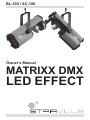
BL-100 / SC-100
Owner‘s Manual
MATRIXX DMX
LED EFFECT
Congratulations on your purchase of this LED Effect Light.
To get the most from your equipment you must read all of this manual
before using it first time.
Table of Contents
1. Safety Instruction........................................................................... 3
2. Technical Specification.................................................................... 4
3. How To Control The Unit............................................................... 4
4. DMX 512 Configuration................................................................. 6
5. DMX512 Connection . .................................................................. 6
6. Troubleshooting............................................................................. 7
7. Fixture Cleaning............................................................................. 8
8. Disposal......................................................................................... 8
EC Declaration of Conformity
We declare that our products (lighting equipment) comply with the
following specification and bears the CE mark in accordance with the
provision of the Electromagnetic Compatibility (EMC) Directive 89/336/
EEC.
EN55014-2: 1997 A1:2001, EN61000-4-2: 1995;
EN61000-4-3:2002;
EN61000-4-4: 1995; EN61000-4-5: 1995, EN61000-4-6:1996,
EN61000-4-11: 1994.
&
Harmonized Standard
EN 60598-1: 2000 +ALL: 2000+A12: 2002
Safety of household and similar electrical appliances,
Part 1: General requirements.
2
1. Safety Instruction
You have to carefully read the instruction, which includes
important information about the installation, operation and
maintenance.
• Please keep this User Guide for future consultation. If you sell the unit
to another user, be sure that he also receives this instruction booklet
thus giving them the necessary information about the use and general
warnings regarding the unit.
• Unpack and check carefully there is no transportation damage before
using the unit.
• Before operating, ensure that the voltage and frequency of power supply match the power requirements of the unit as stated in this manual.
• It’s important to ground the yellow/green conductor to earth in order to
avoid electric shock.
• The unit is for indoor use only. Use it only in a dry location. Exposing the
device to rain or moisture would cause the risk of electrical shock or fire.
• The unit must be installed in a location with adequate ventilation, at
least 15 cm from adjacent surfaces. Be sure that no ventilation slots are
blocked. The electrical work that is necessary for installation must done
by qualified personnel.
• Check the surrounding area and make sure there are no flammable
liquids, water or metal objects that could enter the fixture. If a foreign
object or substance enters the unit, immediately disconnect the mains
power.
• Disconnect the device from the mains power before any servicing or
maintenance.
• In the event of serious operating problem, stop using the unit immediately. Never try to repair the unit by yourself. Repairs carried out by
unskilled people can lead to damage or malfunction. Please contact the
nearest authorized technical assistance centre. Always use the same
type spare parts.
• There are no user serviceable parts inside the fixture. Do not open the
housing or attempt any repairs by yourself. If the fixture shows any
visible damage or in the unlikely event, that your fixture may require
service, please contact your nearest dealer. Always use genuine spare
parts.
3
2. Technical Specification
1. Power supply
Input Voltage:
Power consumption:
AC 230V 50HZ
aprox. 40W
2. LED
Total 52 pcs, (16 x red, 12 x green, 12 x blue, 12 x white)
3. Dimension
420 x 140 x 171mm
4. Weight
BL-100: 3.5 kg • SC-100: 3.0 kg
• The unit is a DMX512 scanner. It features full DMX512 control, stepper
motor with blackout feature.
• It can be operated by DMX512 control or can be used as an individual
unit without controller.
• It can be linked together as many as required in master/slave mode,
and perform the great built-in programmed lighting shows triggered by
music.
• Please use a 3 pin XLR cable/plug when connecting them together.
• It features different pre-programmed chase patterns.
3. How To Control The Unit
(1) Master/Slave operation
The unit can be linked together in daisy chain as many as you need in
master/slave mode to perform the great built-in pre-programmed lighting
shows triggered by music.
In Master/Slave mode refer to the DMX settings below:
Master unit: DMX start address MUST be set to 001. (first DIP switch =
ON, all others are OFF)
Slave units: DMX start address may have any value EXCEPT 001
(example: set the first 3 DIP switches to ON)
*2-light show
Dipswitch 10 “off” means the unit works normally and “on” means
inversion. In order to create a great light show, you can set dip switch 10
“on” on any unit that is linking to the master unit to get contrast movement
4
to the master unit, even if you have two units only. Dipswitch 10 on the
first (Master) unit is no use for the 2-light show as it is the master unit that
operates the light show.
(2) Easy controller (POCKET-MASTER I)
The easy remote control is used only in master/slave
mode. By connecting to the 1/4” microphone jack of the
first unit (its DMX input plug is not used), you will find that
the remote control on the first unit will control all the other
units for Stand by, Function and Mode.
Built-in lighting shows triggered by Easy Controller:
Stand by Blackout the unit
Function 1. Sync. Strobe
2. Two light Strobe
3. Sound Strobe
Mode
Sound (LED OFF)
Select pattern
Select Chase
Pattern
(LED ON)
Chase
(LED Slow Strobe)
(3) Universal DMX controller
When using a universal DMX controller to control the chain of units, you
have to set DMX address by Dip switches from 1 to 9 to make sure all the
units will receive its DMX signal. Please refer to the following diagram to
know how to address your DMX 512 system in the binary code:
DMX 512 Address Chart:
Dip-switches #1 #2 #3 #4 #5
Value
1 2 4 8 16
• Examples:
Channel 01: dip / on: #1 (=1)
Channel 05: dip / on: #1, #3 (1+4=5)
Channel 09: dip / on: #1, #4 (1+8=9)
Channel 13: dip / on: #1, #3, #4
(1+4+8=13)
#6
32
#7
64
#8 #9
128 256
Channel
1
#10
2-light show
Dip switches setting
5
9
13
5
4. DMX 512 Configuration
5. DMX512 Connection
6
The DMX 512 is widely used in intelligent lighting control, with a maximum
of 512 channels.
1. A DMX512 system requires a controller, lighting equipment and cable.
These are connected together in a “daisy chain” with the terminator at
the end. The cable cannot be branched or split into a “Y” cable.
2. The terminator requires a 90-120 Ohm 1/4 Watt resistor soldered between two signal cables.
3. The DMX512 uses a very high-speed signal. Inadequate or damaged
cables, bad solder joints or corroded connectors can easily distort the
signal and shut down the system. A reliable DMX512 system starts
with good quality cables.
4. Each lighting unit needs to have an address set to receive the data
sent by the controller. The address number is between 0-511. The
end of the DMX512 system should be terminated reducing signal errors.
5. 3 pin XLR connectors are more popular than 5 pins XLR.
3 pin XLR: Pin 1: GND, Pin 2: Negative signal (-), Pin 3: Positive signal (+)
5 pin XLR:Pin 1: GND, Pin 2: Negative signal (-), Pin 3: Positive signal (+).
6. Troubleshooting
Following we’re listing a few common problems that may occur during
operation. Here you also find some suggestions for easy troubleshooting:
A. The unit does not work, no light
1. Let a technician check the mains power supply and mains fuse.
2. Let a technician check the mains outlet for proper functioning.
B. Not responding to DMX controller
1. The DMX LED should be on. If not, check DMX connectors and cables to see if they link properly.
2. If the DMX LED is on and no response to the channel, check the address settings and the DMX polarity.
3. If you have intermittent DMX signal problems, let a technician check
the pins on connectors or on PCB of the unit or the previous one.
4. Try to use another DMX controller.
5. Check if the DMX cables run near or run alongside to high voltage cables that may cause damage or interference to DMX interface circuit.
C. Some units don’t respond to the easy controller
1. You may have a break in the DMX cabling. Check the LED for the response of the master/slave mode signal.
2. Wrong DMX address in the unit. Set the proper address.
7
D. No response to the sound
1. Make sure the unit does not receive DMX signal.
2. Check the microphone to see if it is working by tapping on the mic.
E. One of the channels is not working well
1. The stepper motor might be damaged or the cable connected to the
PCB is broken.
2. The motor’s drive IC on the PCB might be out of condition.
7. Fixture Cleaning
The cleaning of internal must be carried out periodically to optimise light
output. Cleaning frequency depends on the environment in which the
fixture operates: damp, smoky or particularly dirty surrounding can cause
greater accumulation of dirt on the fixture’s optics.
• Clean with soft cloth using normal glass cleaning products.
• Always dry the parts carefully.
• Clean the external optics at least every 20 days. Clean the internal optics at least every 30/60 days.
8. Disposal
Do not dispose of the device at the end of his operating life
in your normal domestic waste. This device is subject to the
European Guidelines 2002/96/EC.
• Have the product disposed of by a professional disposal company of by
your communal disposal facility.
• Observe the currently applicable regulations. In case of doubt contact
your disposal facility.
• Dispose of packaging materials in an environmentally responsible manner.
© 2010
Musikhaus Thomann
Treppendorf 30 • 96138 Burgebrach
Germany • www.thomann.de