1
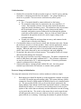
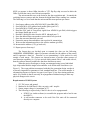
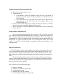
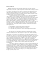
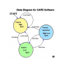
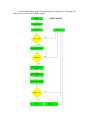
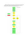
CARS
Computer Aided Racing Statistics
User’s Manual
ELEC 0401/0402 Fall 1999/Winter 2000
Department of Electrical and Computer Engineering
Auburn University
Vehicle Interface
1. Both the DA unit and the FreeWave modem require 12 Volt DC power, and they
must share a common ground for best data transfer. The voltage should be as
noise free as possible. Excessive noise could adversely affect system
performance.
• The +12 terminal should be connected directly to the battery.
• The switched terminal may be connected to any user controlled +12
switch. This terminal is used to close the relays inside the units that
supply the boards with battery power. This minimizes noise injected into
the circuit boards because voltage is always cleanest at the battery
terminals, and ignition systems radiate noise back through the ignition
switch due to their inductive nature. However, both on-vehicle units are
designed for the ignition switch to be used to supply voltage to the
switched terminals.
• Ground wires should be no longer than necessary, and connected to the
vehicle frame or directly to the battery.
2. Care should be taken to avoid excessive shock and vibration to the units. Mount
the enclosures securely to a frame member. Some extreme applications, such as
Baja, may require a suspension or foam packing to preserve circuit board
integrity. While the units were built as well as possible with the equipment at
school, they can be destroyed by not exercising care and good judgment.
3. Do not place the units close to electric motors. The magnetic fields will corrupt
data and possibly damage the electronics.
4. Keep units away from heat, especially exhaust gases. The plastic components are
made of ABS plastic and cannot withstand 100° C. The electronic components
are rated to operate below 50° C ambient temperature. Electronic performance
cannot be guaranteed above that point.
5. Sensors must share a common ground with the DA unit. An extra ground
terminal is provided on the DA enclosure to connect sensor grounds.
Freewave Setup and Initialization
The setup and connection of the Freewave wireless modems is relatively simple:
1.
Both transceivers should be hooked up to the appropriate computer serial port
via an RS-232 straight (not null modem) cable. The custom enclosure (black)
contains the Freewave OEM module DGRO9RAS and is to be installed on the
car. The gray modem (DGR-115) is to be used in the pit connected to the
laptop running Linux and the CARSD data acquisitions software. Connections
should also be made to a 12-volt power source and ground, as well as to the
ignition of the vehicle that can remotely turn the modem box on and off using
a relay inside the box. The switch on the custom box is used to turn the unit
off and bypass the relay in case one wishes to leave the system off at some
point while the car is running. Connecting the antennas is optional for bench
testing because it will not damage the unit. This is so you can do preliminary
testing of the modem’s operation.
2.
The next step in the setup process is interfacing the modems to the computers.
The best way to configure the modems is by using the Windows 95/98
application HyperTerminal. Once inside HyperTerminal, the comm. port on
the PC should be set to a baud rate of 19200, with 8 bits, no parity, and one
stop bit. If this setup is successful, pushing the reset button will create a
screen that will prompt the user to follow a series of steps via a menu in order
to configure the modems to the proper user defined specifications.
3.
In the setup menu, you must have the serial number for each modem entered
into the call book. Each modem must have the other modem’s serial number
in its call book for communication to be possible. The serial number of the
mobile unit (black box) is 901-6824. The serial number of the base station
(gray box) is 571-3755. These numbers are on the units themselves. Next,
you will want to verify that the baud rate is set to 9600 for both modems. This
is done in option (1) of the startup menu. Finally, you will want to make sure
that one unit is set to be the master, and one to be the slave. This is done in
option (0) of the setup menu. If both are master or slave, no communication
will take place because of the conflict.
4.
If these steps are followed correctly, the modems should automatically
establish a link when restarted again. This can be verified by looking at the
LEDs on the front of the units. If there is a solid green, and two intermittent
flashing reds, the modems are connected and sending data. More information
on the front panel LEDs can be found on page 31 of the Freewave manual.
Data Acquisition Unit Operation and Function
The purpose of the data acquisition portion of the CARS project is to convert the
data from the 16 sensors on the car into a format that the computer can interpret. All of
the sensors will output an analog voltage signal ranging between 0 and 5V.
Simultaneously, the data acquisition unit will have to sample the output of each sensor in
a periodic fashion, because there is only one channel with which to transmit data from 16
sources. The data acquisition unit will also have to convert the analog voltage to a digital
value that can be used by a computer. To accomplish this task we used two main
components: an ADC0816 analog to digital converter with a 16-channel analog
multiplexer, and an HC6811 microcontroller.
Even though the 68HC11 does have an onboard 8-channel multiplexer, the
ADC0816 MUX has 16 channels providing greater flexibility. This MUX converts an
analog voltage and outputs an 8-bit digital number, which gives 256 levels, or
approximately .02V/bit resolution. It was determined that this level of accuracy would be
sufficient for the needs of our customers. The maximum clock frequency at which this
MUX can operate is about 1Mhz; therefore a 7473 flip-flop chip was used to halve the
2Mhz E-clock that comes out of the microcontroller.
The microcontroller acts as the brain for the data acquisition unit. It controls the
switching between sensors and also formats the digital data before sending it to a modem.
The following is a list of tasks that the microcontroller must perform per sensor:
1.
2.
3.
4.
Send sensor address to the ADC0816 MUX (pins PB0-PB3)
Send ADC0816 ALE (address latch enable) pulse (pin PA5)
Send ADC0816 START pulse (pin PA6)
Read the EOC (end of conversion) signal from ADC0816 (pin PA0) which triggers
the Output Enable pin as well
5. Read the 8-bit digital value from the MUX (through port C)
6. Store the address that corresponds to sensor which was just read
7. Store the converted data that was read
8. Format the sensor data and address into a packet for transmission
9. Write out the information packet to the wireless modem (pin PD1)
10. Increment the address (if 16, go back to 0).
11. Repeat process from step 1
The format that was decided upon to transmit the data was the following,
1HHHHDD1 0DDDDDDD0, where H represents a header bit (the address of the sensor)
and D represents a data bit. Therefore we are transmitting a 16-bit packet for each
sample of each sensor. This format was chosen because it provides some measure of
error detection capability (i.e. if a byte arrived which started with a 1 and ended with a 0,
then the software daemon would know that there had been an error).
When the project first began, a design was attempted using several individual
logic chips rather than the single microcontroller to do all the tasks listed above (see
Figure 1). The worst problem encountered with this first generation design was that it
was nearly impossible to guarantee a fixed, standard baud rate. The microcontroller is
advantageous because it requires less space (see Figure 2), has fewer timing problems,
and is very flexible in that it can easily be reprogrammed without having to make any
physical changes to the circuit.
Requirements of CARS System
1.
2.
3.
4.
12V DC power and ground
Modem set for 9600 baud, 8-bits, no parity, and 1 stop bit
Sensor output voltage is a maximum of 5V
The following is required only if the D/A box is to be reprogrammed:
a. PCBUG (or similar software) to assemble the program and to load it onto
the 68HC11.
b. A null modem connector to be used if the D/A unit will be connected
directly to a computer.
Normal Operation of Data Acquisition Unit
1. Make sure all connections are secure.
2. Turn the power on.
a. If the remote is wired to the ignitions switch, leave the power switch on
the D/A box in ON position, so that turning the key will function as the
ON/OFF switch.
b. If you choose not to take advantage of the remote power, then short the
remote terminal on the D/A box to the 12V terminal. Then use the
ON/OFF switch only.
3. Push the red Reset button followed by pushing the black Start button. Sometimes
it may be necessary to push both buttons at the same time.
4. The D/A unit will now operate continuously until the power is cut off or the Reset
button is pushed.
Testing of Data Acquisition Unit
After successfully programming the chip we needed to test our circuit. We tested
it by connecting sixteen different potentiometers (see Figure 3) to the sensor inputs of the
D/A unit and evaluated the output from the microcontroller. To see our output, we
connected the D/A unit to a computer (using a null modem connector) and used the GUI
designed for our project to display the data. As we changed the voltage on a certain
“sensor”, we could see the bar graph, corresponding to that sensor, change on the
computer screen.
Software Instructions
The CARS project consists of many hardware and software components. This section
will cover the software aspects of the CARS system. When running, the software will
read data from the serial port and display the sensor channel, the numerical value of the
data for that sensor, and a bar graph representing an overall percentage of the numerical
value.
The main intention of this section is to document the software on the computer
and to provide enough information for a new user to reconstruct and rebuild the software
to his/her personal needs. The original software code and the outside resources for this
project can be found in the appendix.
This section will cover the following topics:
1.
2.
3.
4.
5.
History of software
Hardware and Software requirements
Configuring the System
Installing and Using the Software
Understanding the CARSD computer code
History of Software
When the CARS project was started, the software team was given some basic
requirements to meet. First, a graphical application would be needed to display the values
of 16 sensors. The software had to be able to run on an Intel 486 laptop and be able to
update the graphical display in real-time. Any software tools or compilers that the
software team needed would have to be legally licensed by Auburn University. Finally,
our data would have to be read from the serial port.
The major restrictions in the above guidelines were the Intel 486 laptop and the
cost of software. First, the computer's processor was pretty slow to update a GUI
(Graphical User Interface) in real-time. The software team knew that the laptop would be
too slow to run Windows 95,run a Visual Basic application, and expect the screen to
update in real time. Instead, the software team would have to write the program in C to
gain as much performance as possible. Unfortunately, the licensing for a copy of
Windows 95, a good C compiler (such as Borland C), and a tool kit to construct the GUI
would have cost over two thousand dollars ($2,000). This was too expensive for the
senior design team. To overcome the above restrictions, the software team made the
following decisions:
1. Install Redhat 6.1 Linux Operating System on the laptop
2. Use the GNU C compiler to write the core C program
3. Use the GTK (Gimp Tool Kit) to write the GUI (Graphical User Interface)
By using Linux, we could optimize the kernel (or the brain of the operating
system) for the 486 processor. This would gain us some precious "number crunching
optimizations" to overcome the slow 486 processor. The other main reason for using
Linux was cost. Linux was free and could be downloaded off the Internet. Next, we chose
the GNU C compiler because it was free and came with the Redhat 6.1 distribution of
Linux. Without having to purchase the C compiler, we were able to save money. In
addition, the online documentation on the GNU C compiler was overwhelming.
With a quick web page search, the software team could quickly and easily find answers to
our C programming questions. Finally, the choice of GTK to be used to build the GUI
was the same as the C compiler. It was free and the Internet was flooded with
documentation.
In the end, the decisions we made provided us with excellent documentation, the
software was fast and stable, and we did not have any software purchases. Even though
learning Linux, the GNU C compiler, and GTK was all overwhelming at first, everything
progressed quickly and easily as we became more comfortable with all the different
packages. If we had to do this again, the software team would quickly choose this same
configuration again. We were extremely happy to get a working application without
having to spend any money to do it.
Receiving System Requirements
As with any software, certain hardware requirements need to be met. The
software has been written to run on just about any Intel system; however, we suggest the
hardware have at least the following specifications:
Processor
Memory
Hard Drive
Intel 486 66MHz
16 MB
1.2 GB
The software required is as follows:
Operating System
C Compiler
GTK Libraries
Redhat 6.1 Linux
GNU C 2.9
GTK 1.2
Configuring the Receiving System
Once the necessary hardware is obtained, Linux must be installed on the system in
order to run the CARS software. Installing an operating system can be a little
overwhelming to a person who has never done it before. Therefore, it is normally helpful
to have an experienced individual assist with the installation of Linux. On the other hand,
Redhat 6.1 is very easy to install. The majority of the installation is answering "Yes or
No" to several questions. For this project, we installed "Everything" (an option of which
software packages to install). This ensured that all the necessary software was installed.
By selecting "Everything", the installation consumed roughly 1.1 Gigabytes of hard drive
space. To reduce the amount of drive space, remove all the foreign language
documentation. This reduces the installation to roughly 850 Megabytes. For further
documentation on how to install Linux on a PC, please see the Appendix section "Linux
installation references".
Once Linux is running on the system, the serial port must be properly configured
for a baud rate of 9600. To configure the first COM port (normally the 9 pin serial port
on a PC), perform the following steps:
1. Become "root" user on the Linux system
2. Type "setserial /dev/ttyS0 baud_base 9600"
3. Type "setserial -a /dev/ttyS0" to verify that baud is set properly
If you want your Linux system to setup the serial port in this manner upon bootup,
perform the following steps:
1. Become "root" on the Linux system
2. Type "pico /etc/rc.d/rc.serial" - this will open a text editor and create the file
/etc/rc.d/rc.serial.
3. Enter the line "setserial /dev/ttyS0 baud_base 9600"
4. Type "Ctrl-X" to exit
5. Press "Y" when asked to save the file
6. Press the "Enter" key to write the file to the default file name
7. Logout
Installing and Using the Software
A copy of the software can be downloaded from the CARS Website at:
http://www.eng.auburn.edu/ece/cars/. In addition, a copy of the CARS.C, CARSD.C, and
Makefile source code can be found in the appendix. The software zip file (from the
website) contains precompiled programs of both the working text-based program (
CARSD) and the unfinished GUI (cars). Along with the programs, the source code for
both programs (CARSD.C and CARS.C) and a "Makefile" is included. With the Makefile
in the directory where the source code exists, you can simply type "make cars" or "make
CARSD" to recompile either application. To install the software, perform the following
steps:
1. Download the cars.tar.gz from the CARS website
2. Open a terminal and switch to the directory where the downloaded file exists
3. Un-tar the file with the command "tar xvfz cars.tar.gz - this will create a "cars"
directory where all the files exist.
To run the CARSD program, perform the following steps:
1. Login to the PC and/or open an "xterminal" if you are in graphical mode
2. Once at a prompt, switch to the directory where the software files exist - For
example, "cd ~/cars/" type the command "./ CARSD" - By default, the CARSD
program opens the first com port (/dev/ttyS0) - If nothing happens, then your
serial port is not configured port properly, the data link isn't working properly, or
the bit stream is not being sent to the serial port correctly
3. To exit the CARSD program, type "Ctrl-C"
To run the cars program (the GUI), perform the following steps:
NOTE: You must have the X-window system running and the GTK libraries installed
before running this program.
1. Open an "xterminal"
2. Once at a prompt, switch to the directory where the software files exist - For
example, "cd ~/cars/" type the command "./cars" - By default, the cars program
opens the first com port (/dev/ttyS0) - If nothing happens, then your serial port is
not configured port properly, the data link isn't working properly, or the bit
stream is not being sent to the serial port correctly
3. To exit the program, simply click on the "Quit" button.
Understanding the Code
The C code for the CARSD.C and the CARS.C is very simple. Basically, these
two applications open the serial port (like opening a file), read a byte of data, analyze the
byte to see if it is an identifier or sensor data, stores the sensor data into an array, and
periodically prints the array to the screen. To further describe the two programs, flow
charts, a state diagram, and detailed information about each program is listed below.
Before reading data off the serial port, an understanding of the bit stream is
needed. When the microcontroller processes the data from the sixteen sensors, it outputs
the 4-bit channel number and the 8-bit sensor data in an encapsulated format spanning
two bytes (or sixteen bits).
The first byte looks like this:
1CCCCDD1
The second byte looks like this:
0DDDDDD0
Where C = the channel bits and D = the data bits. When reading these two bytes from the
serial port, several things must happen. First, we have to look for a valid first byte. We
detect a valid first byte by looking for a packet that starts and ends with the number 1.
Once we find that byte, we immediately read another byte from the serial port and
check for the number 0 at the front and end of that packet. If we get both bytes valid, then
we must strip out the four bit channel number, reconstruct the 8 bits of data, and store the
data into an array. Since printing to the screen is normally CPU intensive, a counter was
created to print the array after 16 attempts to read data from the serial port. As one can
see, the program is either processing information or looking for information. This leads to
the state diagram on the following page.
With an understanding of the bit stream and the state diagram, the following flow
chart was used to write the CARSD program.
With the GUI program (cars), the program was much longer because of the GTK calls
to build the window. On the other hand, a large portion of the CARSD program was
copied into the cars program to generate the following flow chart.
Conclusion
Even though all this may seem very overwhelming at first, the concepts and
principles used in the software are very straightforward. By using the Redhat 6.1
distribution of Linux, installation and setup of Linux was very easy. Next, the large
amounts of free documentation that comes with GNU C and GTK made programming
much easier. Finally, the software team spent no money on this project. In the end, the
software team developed a stable, easy, and working software application to print the
data on the computer screen.