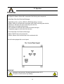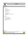
1
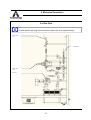
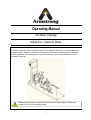
Operating Manual
Hot Water Package
Digital-Flo – Steam to Water
This bulletin should be used by experienced personnel as a guide to the start-up and maintenance of the
supplied package. Selection or installation of equipment should always be accompanied by competent
technical assistance. We encourage you to contact Armstrong or your local Representative if further
information is required.
Read carefully the Start-up and maintenance Instructions of the components before any
starting or shut-off of the supplied package.
1
Digital-Flo – Steam to Water
Start-up should be done by experienced personnel.
Installation of equipment should always be accompanied by competent technical assistance.
Electrical connection should be done by authorized and qualified personnel only.
Installation of equipment should always be accompanied by competent technical assistance.
Read carefully the Start-up and maintenance Instructions of the components before any
starting or shut-off of the supplied package.
Equipment under pressure. Operating temperature above 100°C
Let system cool down before any handling.
THE STEAM SHOULD NOT BE STARTED IF NO FLUID IS RUNNING ON THE COLD SIDE
OF THE HEAT EXCHANGER (WATER SIDE).
On pre-piped packaged units, inspect and tighten all threaded fittings (such as unions, etc.)
that may have loosened during shipment.
2
Digital-Flo – Steam to Water
Safety Information
This instruction manual has been written for the standard Digital-Flo – Steam to Water – Heat Exchanger
Package. Some options might differ on the supplied Package. Refer to the components’ IOM for more
detailed information.
It is required that all workers on the hot water system have read and understood these instructions.
In case of conflicting instructions, the components instructions provided with the hot water system override
the instructions of this user manual provided for the hot water system.
Local codes and/or regulations, as well as plant-specific health and safety requirements shall also be
respected.
If any of the instructions described in this user manual provided by ARMSTRONG INTERNATIONAL SA
are in conflict with the local codes and regulations, please contact your local Representative or
ARMSTRONG INTERNATIONAL SA before initial start-up of the equipment.
For explanations on pictograms and notes, please refer to chapter I.b Explanation of Pictograms and
Notes, page 7.
All personnel involved in the installation, integration, commissioning, maintenance, repair, inspection and
operation of this hot water system shall ensure that all the necessary health and safety requirements are
fulfilled before commencing the work.
They should wear the appropriate personal protective equipment (PPE) together with – if applicable required site-specific equipment.
This instruction manual must be stored in a place near the hot water system and must be accessible for
operators.
It is the responsibility of the company operating the hot water system to keep an equipment history record
of the integrated hot water system, which is to include commissioning records with final settings,
maintenance and inspection reports, as well as reports on modified settings and replacement of parts.
We advise to systematically add the above records to this instruction manual and keep the resulting binder
(hardcopy) or folder (electronic) accessible for operators and service technicians
3
Digital-Flo – Steam to Water
Contents
Page
I.
I.a
I.b
I.c
How to read this operating manual
Definitions
Explanation of Pictograms and Notes
Warranty
II.
II.a
II.b
II.c
II.d
II.e
II.f
Safety
Intended use
Incorrect use
Residual risks
Requirements
Safety Devices
Electrical Engineering
10
10
10
10
11
11
12
III.
II.a
II.b
II.c
Packaging, storage and transport
Packaging
Storage
Transport
13
14
14
15
IV.
IV.a
IV.b
IV.c
Operation
Control Panel Layout
Control Philosophy
Start-up Operation
16
16
18
19
V.
V.a
V.b
V.c
V.d
Mechanical connections
Rear view
Top view
Connections Position
Operating Conditions
21
21
22
23
23
4
6
6
7
9
Digital-Flo – Steam to Water
Contents
Page
VI.
VI.a
VI.b
VI.c
24
24
24
25
Electrical connections
Power supply
Connections
Electrical drawing
5
I. How to read this operating Manual
I.a Definitions
Operating Company
The operating company is either the owner of the hot water package or has rented it. The operating
company integrates the hot water package in the installation used for industrial purposes.
Qualified Staff
Qualified staff carries out their work and recognize potential risks due to their professional training. In
addition, they are familiar with relevant rules, accident prevention regulations, and special circumstances
within a company.
Qualified staff installs and services the hot water package system.
Operators
The operators receive on-the-job training and know about possible dangers that may arise from incorrect
use. They are familiar with all required protective gear and personal protection measures, all applicable
rules, all accident prevention regulations, and all operating conditions.
6
I. How to read this operating Manual
I.b Explanation of Pictograms and Notes
Never remove warning signs or have them blocked from view. The risks which the warning signs refer to are described in the text
next to the pictogram.
CAUTION!
This pictogram marks safety instructions which must be observed to avoid danger to the system and
Its operation.
All signs on the system must be readable and the information on the signs must be followed at all times.
WARNING - High Voltage!
This pictogram is used to warn against electric shock hazard. Only qualified electricians may work on the
system's electrical equipment. Make sure that all national and local safety requirements are observed.
WARNING - Suspended Loads!
This pictogram is used to warn against possibly dangerous situations involving falling loads which could lead
to serious injury or death. Only qualified staff may work on the package system. Make sure that all national
and local safety requirements are observed.
WARNING - Toxic Substances!
This pictogram is used to warn against the danger of toxic substances. Only qualified staff may work on the
package system. Make sure that all national and local safety requirements are observed.
observed.
WARNING - Hot Surfaces!
This pictogram is used to warn against the danger of hot surfaces. Only qualified staff may work on the
package system. Make sure that all national and local safety requirements are
WARNING - Fire!
This pictogram is used to warn against possibly dangerous situations involving fire which could lead to
serious injury or death. Only qualified staff may work on the package system. Make sure that all national and
local safety requirements are observed.
WARNING - Explosion Hazard!
This pictogram is used to warn against possibly dangerous situations where an explosion could lead to
serious injury or death. Only qualified staff may work on the package system. Make sure that all national and
local safety requirements are observed.
7
I. How to read this operating Manual
WARNING - Crushing Hazard!
This pictogram is used to warn against possibly dangerous situations where moving parts can lead to serious
crushing injuries or death. Only qualified staff may work on the package system. Make sure that all national
and local safety requirements are observed.
MANDATORY Use of Safety Gloves!
This pictogram is used to warn against possibly dangerous situations which can only be avoided by wearing
safety gloves.
MANDATORY Use of Protective Clothing!
This pictogram is used to warn against possibly hazardous situations which could lead to moderate physical
injuries, making the use of protective clothing mandatory.
MANDATORY Use of Ear Protection!
This pictogram is used to warn against possibly hazardous situations which could lead to ear damage.
MANDATORY Regulation to Switch OFF the Package System!
Switch off the package system at the control unit. Secure the main switch against unintentional or
unauthorized switch-on with one or more padlocks.
PROHIBITED!
This pictogram is used to warn against smoking and/or open fire near a package system.
NOTE:
This pictogram is used to highlight special information on key functions or special user tips which will help
you make full use of all the functions the package system has to offer.
8
I. How to read this Operating Manual
I.c Warranty
These OMs are based on the technological and product-specific parameters of the supplied package
system. The manufacturer does, however, reserve the right to add information to these OMs.
The manufacturer offers guarantees and warranties only according to its "General Terms and Conditions of
Sale and Delivery".
Warranty claims as well as liability claims in case of personal and/or property damage will be rejected if
caused by one or more of the following circumstances:
The package system was
- used for purposes other than those for which it was intended.
- not operated in accordance with the instructions given in this OM.
- operated after safety devices had been disabled.
- was operated with unacceptable operating materials.
- was operated after constructional and/or functional changes had been made without consulting the
manufacturer in advance.
- was equipped with spare parts neither delivered nor approved of by the manufacturer.
- was improperly installed, commissioned, operated, repaired and/or serviced.
- was not regularly serviced.
- was damaged by Acts of God, disasters or through foreign objects.
See back-cover for more information on warranty period.
9
II. Safety
II.a Intended use
NOTE:
Always use spare parts and equipment recommended by ARMSTRONG INTERNATIONAL
SA. Contact your Representative or Armstrong International SA for more details if
required.
The Special Heat Exchanger Package is exclusively designed for heating water with steam. Always
observe the limit values and operating conditions specified in chapter V.d Operating Conditions, page 23.
II.b Incorrect Use
CAUTION!
Incorrect use of either the entire package system or parts of it may lead to fatal or lethal
injury of persons and severe damage to the package system or environment.
Never use the package system for the production of products or for process technology
methods other than specified.
The manufacturer cannot be held liable for any damage or injury occurring as a result of
the installation and use of parts purchased from other manufacturers (i.e. of parts which
are not approved of by the manufacturer as either accessory or spare part).
II.c Residual Risks
It is impossible to exclude all residual risks, even if the package system is used correctly.
These residual risks do not arise from the package system itself, but are in general caused by
inattentiveness or incorrect operation.
Strictly adhere to
- the general statutory and operational safety regulations.
- all approved technical rules regarding safe and professional work.
- all safety instructions contained in this Operating Manual.
- safety instructions in suppliers' documentation, especially regarding troubleshooting and maintenance
work carried out on this package system.
- the information given on the safety marks of the package system.
- the rules on accident prevention.
- the instructions on environmental protection.
10
II. Safety
II.d Requirements
Of the Operating Company
The operating company is required to
- ensure that any work on the package system is carried out by persons who have been trained and are
familiar with basic occupational safety and accident prevention regulations.
- provide necessary personal safety gear for the operator.
- regularly check the safety devices and the protective gear provided.
- be certain that the operator has read and understood the Operating Manual (OM), especially the safety
and warning notices.
Of the Operators
Operators are required to
- observe the basic occupational safety and accident prevention regulations.
- read this OM, especially the safety and warning notices and to ask about anything that is unclear.
- report damage to the package system immediately and, in case of danger, shut the package system down
immediately.
II.e Safety Devices
The package system is equipped with safety devices according to applicable European Directives.
However, the integration of the package system into thermo-processing equipment can lead to dangers
which can only be recognized and avoided with a proper knowledge of all design-based and functional
details of the thermo-processing equipment. Due to these circumstances, ARMSTRONG INTERNATIONAL
SA cannot specify every possible safety-relevant measure. Here are some examples of possible dangers:
- excess temperature
- no flow on secondary side before starting
- increase of pressure
If available, the safety devices of the thermo-processing equipment should be connected to the package
control to ensure that starting and operating the package is only possible when conditions are safe.
All safety devices must always be in perfect and operative condition.
The qualified staff must regularly check the safety devices to ensure that they are fully functional.
Do not deactivate any of the safety devices on the package system.
All safety devices must be in full working order before starting the package system for the first time.
Do not start up the package system if any safety device is defective. Stop the package system if a safety
device fails during operation and restart it only after the safety device has been repaired.
Wait until the package system has been shut down and secured before removing any safety devices.
11
II. Safety
II.f Electrical Engineering
MANDATORY regulation to switch off the package system!
Go to the control unit and switch off the main supply.
Secure the main supply against unintentional or unauthorized switch-on with one or more
padlocks.
Only skilled electricians may access the electrical components of the package system for
maintenance purposes.
Check the operability of the protective systems after finishing the maintenance work.
Always use original fuses with the specified amperage.
12
III. Packaging, Storage and Transport
WARNING - Suspended Loads!
Never step under a suspended load!
Use only approved hoisting equipment, such as for example handling chains which comply
with DIN EN 818, handling ropes which comply with DIN 3088, hoisting belts which comply
with DIN 61360 or hoisting straps which comply with DIN EN 1492-1.
CAUTION!
Ensure that the installation is transported without being knocked or pushed.
Observe all signs on the packaging. Additional transport locking devices were installed by
the manufacturer for transport purposes. Remove these transport locking devices only just
before assembly.
Remove these transport interlocks before commissioning!
MANDATORY use of safety gloves!
Remove nails sticking out of the wooden boxes immediately after opening!
NOTE:
When transporting the package system, observe the transport regulations of
ARMSTRONG INTERNATIONAL SA, see chapter III.c Transport, page 15.
General and local safety and accident prevention regulations must be explained to all
staff and must be followed during unpacking, storing and transportation work.
The regulations must be stored close to the package system for future reference.
13
III. Packaging, Storage and Transport
III.a Packaging
Unless specifically agreed otherwise, packaging complies with the packaging guidelines.
Each packing unit is strapped to a pallet, clad with edge protectors and put into a tailored
crate or box.
Dispose of waste, remainders and packing separately as specified by valid local
regulations.
NOTE:
ARMSTRONG INTERNATIONAL SA will not accept returned packaging materials free of
charge!
III.b Storage
Store the package system in working position, clean, dry, dust-free and protected against
direct sunlight. Properly cover the package system.
If you plan to store the system for a long period of time, agree the precisely defined storage
conditions in writing.
Do not remove or damage the package system's packaging and conservation materials
during storage.
Ensure that transport locks inside packing are not removed. Transport locks may only be
removed by authorized personnel during assembly.
Avoid high temperature differences and condensation.
- Minimum storage temperature 0 °C
- Maximum storage temperature +40 °C
- Maximum air humidity 50 %
CAUTION!
Never stack loads onto the packaging. This may damage the packaging and the contents.
14
III. Packaging, Storage and Transport
III.c Transport
CAUTION!
The package system is equipped with sensitive electronic components. Ensure that the
installation is transported without being knocked or pushed.
Ensure that all piping is unpressurized before transporting the package system.
Please pay attention to the shipping list instructions. Ensure that the package system cannot slide when
being transported (e. g. by truck). These transport instructions are only valid in their original packing.
Make sure that surfaces and seals are not misshapen or damaged while being transported.
Ensure that all moving parts are secured in place while being transported. Transport locks may only be
removed by authorized personnel during assembly.
Forklift trucks are used to transport the package system to its installation location.
Take individual maximum loads into account when choosing suitable transport and hoisting equipment!
The transport and hoisting equipment must be provided by the customer.
Check the shipment as to its completeness, transport damage, and the stability of screwed connections.
Check the package system for external damage as soon as it arrives on site. Immediately report damages.
Report any transport damages immediately after receiving the package system to the
shipping department of ARMSTRONG:
ARMSTRONG INTERNATIONAL SA
Parc Industriel des Hauts-Sarts
Deuxième Avenue, 4
B-4040 Herstal
Phone: +32 4 240 90 90
Telefax: +32 2 240 40 33
eMail: [email protected]
Internet: www.armstronginternational.com
15
IV. Operation
The Digital-Flo Steam to Water skid is composed of the following main components :
On the Water Side of the Plate Heat Exchanger :
- Digital Mixing Valve, could be a DRV40 or DRV80 depending on the size,
- Isolation valves on cold water inlet, mixed water outlet, return and mixing valve hot inlet,
- Strainers on cold water inlet, return and mixing valve hot inlet,
- Check valve on cold water inlet and return,
- CIP connections on cold inlet and hot outlet of the heat exchanger,
- Temperature gauges on cold water inlet and return.
On the Steam Side of the Plate Heat Exchanger :
- Electric ON/OFF valve on the steam inlet,
- Strainer, isolation valve and steam trap on the condensate side.
The skid is also equipped with a control panel.
IV.a Control Panel Layout
IMPORTANT :
Equipment under pressure. Operating temperature above 100°C
Let system cool down before any handling.
16
IV. Operation
1. Lights :
a. Power ON :
Type : Information
Indication : Healthy Supply
Color : White
b. Solenoid Valve ON :
Type : Information
Indication : Steam Isolation Valve is open
Color : Green
2. Light Button :
a. Reset Alarm Mixing Valve :
Type : Information/Reset
Indication : High Temp Alarm
Color : Red
IMPORTANT :
Equipment under pressure. Operating temperature above 100°C
Let system cool down before any handling.
17
IV. Operation
IV.b Control Philosophy
1. The control panel on the skid is supplied with power as and when the system has to operate.
2. When the panel is supplied with power, the system operates as follows :
a. When system is operational with no fault signal, the automatic steam shut-off valve is open.
b. The Digital Mixing Valve has fully integrated actuator, controller and temperature probes, and will
control on its own the mixed water temperature based on the setpoint (see component specific
documentation for more information).
3. When water temperature failure occurs (too high temperature), the Digital Mixing Valve integrated relay
will trip out. The automatic steam shut-off closes and the ‘’Reset Alarm Mixing Valve’’ light button is
ON.
See specific component documentation for more information on possible failure on the Digital Mixing
Valve.
4. When problem has been fixed, press on the ’Reset Alarm Mixing Valve’’ light button.
The Digital Mixing Valve will switch off for a few second and then restart automatically.
The automatic Steam shut-off valve will open.
IMPORTANT :
Equipment under pressure. Operating temperature above 100°C
Let system cool down before any handling.
18
IV. Operation
IV.c Start-Up Operation
THE STEAM SHOULD NOT BE STARTED IF NO FLUID IS RUNNING ON THE COLD SIDE
OF THE HEAT EXCHANGER (WATER SIDE).
1. Before Start-up : (this section consider components that should be installed by the user)
a.
b.
c.
d.
Ensure that both the steam isolation and control valves are fully closed
Ensure that the heat exchanger is fully drained of condensate
Start cold circuit first, then the steam side.
Cold Circuit :
i.
ii.
iii.
iv.
v.
vi.
e.
Fully vent the system;
Close shut off valve fitted between pump and exchanger;
Fully open valve fitted into outlet line from the exchanger;
Start the circulation pump normally placed by the inlet;
Gradually open closed shut off valve between pump and exchanger;
Vent system again if necessary.
Hot (steam) Side :
i.
ii.
iii.
Open all isolation valves on the condensate side.
Isolation valves on steam side have to be opened SLOWLY.
Slowly open the main steam isolation valve until you have steam at the inlet to the
control valve. Allow pressures and temperatures to equalize before fully opening
the steam isolation valve.
Set the control valve in order to have 1 barg steam entering into the heat
exchanger – this will reduce water hammer of any condensate in the steam line
and the pressure/thermal shock of the exchanger
IMPORTANT :
Equipment under pressure. Operating temperature above 100°C
Let system cool down before any handling.
To avoid flashing of the water on the secondary side, water pressure should always be
greater than steam pressure.
19
IV. Operation
2. Check for proper operation :
a.
Check for pressure pulses in the system caused by the pumps or control valves. If found,
stop operation and rectify.
Continuous pressure pulses will result in fatigue failure of the HE.
b.
Visually check the unit for leakage.
c.
Ensure that the steam trap is working correctly – this will prevent water clogging inside the
heat exchanger.
d.
“Cold leakage” is caused by a sudden change in temperature. The sealing properties of
certain elastomers are temporarily reduced when the temperature changes suddenly.
No action is required as the gaskets should re-seal after the temperature has stabilized.
Demountable plate heat exchangers can always leak. We advise you to take this into
account while installing. Preferably you should install a drip tray underneath the heat
exchanger skid to prevent leakages onto the floor and/or harm to electrical equipment.
(Short circuit/moisture damage).
Read carefully the Start-up and maintenance Instructions of the components before any
starting or shut-off of the supplied package.
IMPORTANT :
Equipment under pressure. Operating temperature above 100°C
Let system cool down before any handling.
To avoid flashing of the water on the secondary side, water pressure should always be
greater than steam pressure.
20
V. Mechanical Connections
V.a Rear View
For exact position and rating of the connections, please refer to the supplied drawing.
Return Water
IN
Cold Water IN
Mixed Water
OUT
Steam IN
Supplied skid might differ from this image.
21
V. Mechanical Connections
V.b Top View
For exact position and rating of the connections, please refer to the supplied drawing.
Return IN
Condensate
OUT
Supplied skid might differ from this image.
22
V. Mechanical Connections
V.c Connections Position
For exact position and rating of the connections, please refer to the supplied drawing.
II.d Operating Conditions
1. SIDE 1 :
Fluid :
Maximum Allowable Pressure :
Max. Temperature :
Max. Operating Pressure :
Saturated Steam
4 barg
142°C
1 barg
Fluid :
Maximum Temperature OUT :
Max. Pressure :
Max. Temperature :
Min. Flow :
Water
70°C
10 barg
100°C
19 l/min (for unit with DRV40)
38 l/min (for unit with DRV80)
2. SIDE 2 :
IMPORTANT :
Equipment under pressure. Operating temperature above 100°C
Let system cool down before any handling.
To avoid flashing of the water on the secondary side, water pressure should always be
greater than steam pressure.
23
VI. Electrical Connections
Electrical connection should be done by authorized and qualified personnel only.
Installation of equipment should always be accompanied by competent technical assistance.
VI.a Power Supply
The electrical panel should be supplied with:
Terminals :
230V – 1ph – 50Hz Tolerance : +/- 10V
L1 / N1 / PE
VI.b Connections
The electrical panel is supplied fully pre-wired. All components supplied on the package are already
connected to the panel.
There is one Volt Free signal available for BMS. This signal give the information coming from Mixing Valve
fault relay:
1. SIGNAL OUT (to BMS)
a.
Mixing Valve Failed
teminals : 40-41
Volt free contact
Electrical connection should be done by authorized and qualified personnel only.
Installation of equipment should always be accompanied by competent technical assistance.
24
VI. Electrical Connections
VI.c Electrical drawings
25
VI. Electrical Connections
VI.c Electrical drawings
26
Armstrong International SA Warranty
Armstrong International SA. (“Armstrong”) warrants to the original user of those products supplied by it
and used in the service and in the manner for which they are intended, that such products shall be free
from defects in material and workmanship for a period of one (1) year from the date of installation, but not
longer than 15 months from the date of shipment from the factory [unless a Special Warranty Period
applies, as listed below]. This warranty does not extend to any product that has been subject to misuse,
neglect, or alteration after shipment from the Armstrong factory. Except as may be expressly provided in
a written agreement between Armstrong and the user, which is signed by both parties, Armstrong DOES
NOT MAKE ANY OTHER REPRESENTATIONS OR WARRANTIES, EXPRESS OR IMPLIED,
INCLUDING, BUT NOT LIMITED TO, ANY IMPLIED WARRANTY OF MERCHANTABILITY OR ANY
IMPLIED WARRANTY OF FITNESS FOR A PARTICULAR PURPOSE. The sole and exclusive remedy
with respect to the above limited warranty or with respect to any other claim relating to the products or to
defects or any condition or use of the products supplied by Armstrong, however caused, and whether
such claim is based upon warranty, contract, negligence, strict liability, or any other basis or theory, is
limited to Armstrong’s repair or replacement of the part or product, excluding any labor or any other cost
to remove or install said part or product, or, at Armstrong’s option, to repayment of the purchase price. As
a condition of enforcing any rights or remedies relating to Armstrong products, notice of any warranty or
other claim relating to the products must be given in writing to Armstrong: (i) within 30 days of last day of
the applicable warranty period, or (ii) within 30 days of the date of the manifestation of the condition or
occurrence giving rise to the claim, whichever is earlier. IN NO EVENT SHALL ARMSTRONG BE LIABLE
FOR SPECIAL, DIRECT, INDIRECT, INCIDENTAL OR CONSEQUENTIAL DAMAGES, INCLUDING,
BUT NOT LIMITED TO, LOSS OF USE OR PROFITS OR INTERRUPTION OF BUSINESS. The Limited
Warranty and Remedy terms herein apply notwithstanding any contrary terms in any purchase order or
form submitted or issued by any user, purchaser, or third party and all such contrary terms shall be
deemed rejected by Armstrong.
Special Warranty Periods are as follows:
- The Brain® DRV40 shall have a 5-year guarantee against failure caused by materials or
workmanship provided by Armstrong.
- The Brain® DRV80 shall have a 5-year guarantee against failure caused by materials or
workmanship provided by Armstrong.
ARMSTRONG INTERNATIONAL S.A.
Parc Industriel des Hauts-Sarts, 2e Avenue 4, B-4040 Herstal - BELGIUM
Tel: +32 (0)4 240 90 90 - Fax: +32 (0)4 240 40 33
ARMSTRONG INTERNATIONAL ITALIANA S.r.l.
Via S. Botticelli 80, 10154 Torino - ITALY
Tel: +39 011-20 00 35 - Fax: +39 011-24 25 744
ARMSTRONG INTERNATIONAL S.A.
Manchester Business Park
3000 Aviator Way – Manchester – M22 5TG - UNITED KINGDOM
Tel: +44 (0)161 266 2279 - Fax: +44 (0)161 266 1001
ARMSTRONG SERVICE FRANCE
BP 102 – route du Hoc, 76700 Gonfreville l’Orcher - FRANCE
Tel: +33 02 35 53 68 35 - Fax: +33 02 35 53 68 37
OM-L37097 rev.1 – june 2013
27