1
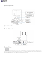
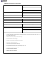
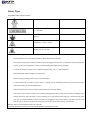
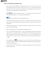
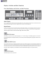
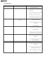
In His Name Atho Therm 011 (AT 011 Furnace) User Manual All Rights Reserved, 4102, KFP Dental Table of Contents Table of Contents…………………………………………………………………………………………………………………………………2 Dear customer…………………………………………………………………………………………………………………………………….4 Product Specifications Unpacking the Product………………………………………………………………………………………………………………………..5 AT 011 Package Contents …………………………………………………………………………………………………………………...5 System Components……………………………………………………………………………………………………………………………6 System Connections…………………………………………………………………………………………………………………………….6 Technical Specifications……………………………………………………………………………………………………………………….7 Safety Tips…………………………………………………………………………………………………………………………………………..8 Furnace Installation and Operation …………………………………………………………………………………………………….9 Digital Display and Switches Front Panel Displays and their Functions…………………………………………………………………………………………….01 Mimic Graphic Display…………………………………………………………………………………………………………………………01 Digital Graphic Display………………………………………………………………………………………………………………………..01 PRG.NO Switch……………………………………………………………………………………………………………………………………01 PRG.EDIT Switch………………………………………………………………………………………………………………………………….01 STEP Switch…………………………………………………………………………………………………………………………………………01 Numerical Switches……………………………………………………………………………………………………………………………..00 ENTER Switch……………………………………………………………………………………………………………………………………….00 CLEAR Switch……………………………………………………………………………………………………………………………………….00 Over Ride (VAC-Air) Switch………………………………………………………………………………………………………………….00 End Over Ride……………………………………………………………………………………………………………………………………..02 LIGHT Switch………………………………………………………………………………………………………………………………………..02 DOWN Switch………………………………………………………………………………………………………………………………………01 UP Switch…………………………………………………………………………………………………………………………………………….01 DRY Switch……………………………………………………………………………………………………………………………………………01 IDLE Switch…………………………………………………………………………………………………………………………………………..01 NIGHT Switch……………………………………………………………………………………………………………………………………….01 CALIB Switch…………………………………………………………………………………………………………………………………………04 C and F Switches…………………………………………………………………………………………………………………………………..04 START/STOP Switches…………………………………………………………………………………………………………………………..04 Product Operating AT-011 Furnace Operating…………………………………………………………………………………………………………………… 05 0. LOW TEMP……………………………………………………………………………………………………………………………….05 2. PRE-HEAT TIME………………………………………………………………………………………………………………………..05 1. HEAT RATE………………………………………………………………………………………………………………………………05 4. HIGH TEMP……………………………………………………………………………………………………………………………..05 5. HOLD TIME……………………………………………………………………………………………………………………………...05 6. COOL TIME (for Cooling) …………………………………………………………………………………………………………05 7. VACUUM LEVEL (VAC.) ……………………………………………………………………………………………………………05 8. EVACUATION TEMP…………………………………………………………………………………………………………………05 9. VENT………………………………………………………………………………………………………………………………………..05 The allowable Range for Programmable Furnace Parameters……………………………………………………………….05 Programming AT011 Furnace Programming………………………………………………………………………………………………………………..07 Displaying and Revision of parametric Values during Thermal Cycle Execution…………………………………….09 Programming and Revision of other Programs during Main Program Execution……………………………………21 IDLE Mode Programming and Functions………………………………………………………………………………………………..21 AUTO IDLES Mode (Automatic Idling) …………………………………………………………………………………………………..21 The NIGHT Program………………………………………………………………………………………………………………………………20 The DRY Program………………………………………………………………………………………………………………………………….20 The Allowable Limits of Programmable Furnace Parameters………………………………………………………………..22 The Door Test Program…………………………………………………………………………………………………………………………22 Service & Maintenance Calibration……………………………………………………………………………………………………………………………………………..21 Safety Principles……………………………………………………………………………………………………………………………………..21 Tips to Increase Useful Life……………………………………………………………………………………………………………………..24 Troubleshooting……………………………………………………………………………………………………………………………………..26 Contact Us ……………………………………………………………………………………………………………………………………………..27 Dear customer The product you have just purchased has been designed and manufactured in accordance with the latest scientific knowledge and more than two decades of experience in the field of porcelain curing furnaces. As an industrial unit, Kousha Fan Pars Company follows customer-oriented policies and adapts its activities by taking into account your views. Please do not hesitate to inform us of your views regarding our products. Due to the critical role of porcelain curing furnaces in dentistry, they must be designed carefully for precise and speedy operation. Through using high quality industrial components and parts in our products, we have realized the above conditions. Your furnace can be used for various operations in dentistry laboratories including degassing alloys, curing various kinds of porcelain, glazing, etc. The AT-011 Porcelain Curing Furnace is a fully automatic product equipped with a precise control system for high quality curing in the least possible time. With the hope of enticing your satisfaction, Kousha Fan Pars Engineering and Manufacturing Product Specifications Unpacking the Product Your furnace package is designed for proper physical protection in accordance with the requirements of related standards. The package is resistant to water penetration and mechanical pressure as specified in the relevant standards. To take the furnace and its accessories out of its box, first position the box with the sign points upward. Then, open the upper part and take out the soft protective elements and the furnace. Take great care in handling the furnace and position it in a suitable location. Note: For safe and easy future handling, keep the box and packaging accessories in a safe place. At 011 Package Content 0. AT 011 Furnace 2. User Manual 1. Special Vacuum Hose 4. Furnace Cable 5. Base 6. Pins & Ceramic Tray 7. Vacuum Pump System Components System Connections Electrical Connections Electrical Fuses At the back of the furnace, there are two fuses for the mains connection. The specifications of these fuses are printed on their external body. In case of discrepancies between these electrical specifications with those applying in your area, replace these fuses with proper ones. Technical Specifications of the Furnace Dimensions and Weight Width: 191 mm Depth: 171 mm Height: 541 mm Weight: 20 kg Furnace Chamber Dimensions Diameter: 95 mm Height: 61 mm Furnace Chamber Temperature Max. 0211 C (2092 F) Electrical Specifications Power Supply 221 VAC, 51 Hz (Urban power supply in Iran) Rated Power Max. 0611 W Vacuum Pump Specifications Power Supply 221 VAC, 51 Hz (Urban power supply in Iran) Rated Power 251 W Max. Vacuum Pressure 741 mmHg Dimensions: 121mm x 001mm x 221mm Weight: 6.5 kg Furnace General Specifications: - The latest technology and a high-precision temperature controller are used so as to provide users of the AT-011 Furnace with optimum results. - Reduced operation time; New production technology - Full demonstration of furnace stages - Chamber thermal isolation with high quality insulators - Spiral Quarts Tube thermal element - Thermal sensor (Platinum/Radium-Platinum) - Curing temperature tolerance: plus or minus 0 degree C (11.8 F) - Controllable vacuum pressure at all stages - Automatic temperature calibration - Software-aided vacuum calibration Safety Tips: The Safety Labels on the Furnace: Risk of electric shock Dangerous voltage Use 221 VAC power supply with max. 011 tolerance Connect the earth connection of the furnace The heated surface temperature range is between 25 and 451 deg C The surface of the lift can damage the objects that lie in its path Safety Precautions during Installation: - Pay close attention to the warnings printed on labels attached to the product - If the safety tips as well as ambient conditions and operating precautions are not adhered to while installing this product, certain parts might fail as a result, and the whole system might also be damaged. - In case of fluctuations in electricity or insufficient supply power, use a 2.5 kW transformer. - Keep inflammable materials away from the furnace. - Avoid knocking or hitting furnace screen or furnace display. - In case of observing any smoke, unusual smell, or irregular sound, immediately disconnect the furnace from the mains and contact our Technical Department. - Avoid using the furnace mains connection jointly with other electrical devices. - Your furnace has an earth connection for increased safety against electric shock to the operator or damage to the building caused by static electricity. If your building has an earth well and the plugs are connected to this well, then you can simply establish the earth connection by plugging in the furnace cable. In the absence of an earth well, be sure to connect a screw on the body of the furnace to a metal water pipe via a coated wire. Warning: Avoid connecting the earth wire to a gas pipe Important: Study the instruction manual completely before operating the furnace. Furnace Installation and Operation 0. Removing the surrounding plastofoams, carefully take the furnace out of its box and put it on a flat standard laboratory table. There must be a free distance of at least 25 cm on all sides of the furnace (Warning: The table top or its legs must not be made of metal because metallic surfaces increase the risk of electric shock. Use a fiber glass or wooden table instead). If the ambient temperature is below 05 C, after turning on the furnace, allow it to 2. remain at room temperature for 11 minutes before starting operations. 1. Protect the furnace from direct sunlight and direct wind. 4. Place the vacuum pump preferably under the table on a leveled horizontal surface. Note: Check the vacuum pump suction and discharge openings behind the furnace to make sure they are free from foreign objects. 5. Connect the connecting hose to the respective connections on the pump and furnace. Push the hose ends to prevent possible leakage. 6. Plug in the pump cable into the respective plug at the back of the furnace. 7. If you use a protective transformer (at least 2.5 kW) or voltage stabilizer, connect the furnace power cable to the mains, or, alternatively, plug it in an independent and safe mains power supply. The internal cables and wiring of your laboratory must support a current of 05 A. If you cannot establish that the wiring can tolerate 05 A then connect the furnace directly to the electricity power meter through a 2 x 2.5 cable. 8. Put the ON/OFF Switch ( ) on the ON position to turn on the furnace. The furnace should start and its top door should open. The left display shows the temperature inside the furnace and the right display indicates the idling (IDLE) mode. 9. Upon starting the furnace, remember to wait 11 seconds before operating it. This is essential for correct operation of the product. Displays: Switches and their Functions Front Panel Displays and Switches, and their Functions Mimic Display This is a diagram which demonstrates (through LEDs) the current positing of the furnace as well as the current programming and program execution stages and the execution of heating cycles. Digital Display Your furnace comes with two multimode (right and left) digital displays. The left display shows the numerical values of 9 parameters (heat, various times, vacuum level, error messages, and the faults). The right display indicates program numbers as well as the Idle, Night, Calib, and Dry modes. PRG NO Switch This switch is used to select the required program (1 to 99) from among 99 available programs, or to execute and change programs. Pressing this switch, you can select your desired program by typing the number on the keyboard. PRG EDIT Switch This is used for observing or changing parameter values for a specific program. Press this button to display the 9 parameters on the screen and then, apply the required change or programming. Pressing the STEP button, you can review the numerical values of the parameters (from LOW TEMP to VENT) and enter the correct values in their place. Upon completion, press ENTER to save the implemented changes in the system memory. STEP Switch: This switch performs two operations: - By pressing it several times in quick succession, you can observe the following parameters on the left digital display: 0. Temperature 2. The remaining time of all temporal parameters 1. The vacuum level in the heating compartment 4. The elapsed time in the currently running program - By each time of pressing STEP once while using the PRG EDIT for planning or observing parameters, you can observe one of the nine parameters and its numerical value. Thus, through pressing STEP nine times, all the parameters can be checked. Numerical Keyboard These 01 keys are for entering the required program number or the numerical values in the furnace programs. ENTER Switch This is for entering the numerical values of parameters. CLEAR Switch This key performs the following: 0. Erasing the numbers entered through the numerical keys and returning the display to viewing parameters (the reverse of what is done via STEP and ENTER). 2. Cutting off alarm sounds 1. Automatic testing of the furnace top door (See Testing the Top Door). OVER RIDE Switches Sometimes, upon completion of the heating cycle programs for curing the prosthetic teeth and after opening the furnace door, the required quality is not obtained (regarding curing temperature and vacuum level). For this reason, your furnace is provided with the possibility of repeating the heating cycle with or without vacuum (in the presence of air) at 21 deg C higher than the HGIH TEMP limit. In such a case, the AIR and VAC LEDs would start blinking and are ready to receive further orders. The VAC key is for repeating the cycle from the HOLD TIME stage onward at a higher temperature in vacuum, and the AIR key does the same in air (without vacuum). The OVER RIDE capability has three modes: - Mode 0: OVER RIDE is not executed: In this mode, we want to prevent the furnace from going to V+OVER RIDE upon completion of the heating cycle. To this end, first (before running the program) press END and observe the word OVER on the right display and either 1 or 0 (or 0 or 2) on the left display. Select 1 to stop the program from going to OVER RIDE mode. - Mode 2: Press END and select “0” to enter the OVER RIDE mode. Thus, upon running each program in the curing cycle and upon expiring of HOLD TIME, the furnace gives the operator one minute to use the OVER RIDE capability. - Mode 1: In case more time is needed after opening of the door for checking the results, you can use the third mode. Simply press END and enter “2” for setting the allowable waiting time before executing OVER RIDE at 2 minutes. Note: In this mode, The HOLD TIME in the curing operation shall be at most 0 min after the furnace temperature has reached the 21 C limit beyond HIGH TEMP (the green LED turns on), and the furnace door opens only after this time has elapsed. After each time of pressing AIR or VAC keys, you can set the temperature at 0 C more than the last OVER RIDE temperature so as to repeat the HOLD TIME for another minute. Upon completion of OVER RIDE program, the oven door automatically opens after 0 min. The OVER RIDE operations can be repeated until the desired results have been obtained without your having restart the heating cycle. Note: The OVER RIDE capability can be applied in other research and test programs as well to obtain the required temperature. END (OVER RIDE) Switch This key is used in the OVER RIDE mode (VAC or AIR) to stop the furnace operation. Upon pressing this key, the furnace door opens, allowing the operator to repeat the VAC/AIR OVER RIDE mode. The difference between END and STOP keys is that the former does not fully stop the running program and can be used at any time during OVER RIDE. Another application of END is programming the furnace in three modes, namely, Mode 1, Mode 0, and Mode 2 (as was explained above). LIGHT Switch This key provides ambient illumination in the work place (the area surrounding the furnace door and its base). Pressing this key would turn on two lamps and pressing it again would turn off these lamps. The maximum illumination time is 0 min. DOWN SWITCH This is used to lower the furnace door to the required height. Note: The DOWN key doen not operate during the running of the main programs or while the DRY, NIGHT, and IDLE programs are being executed. UP Switch This key is used for lifting the furnace door to the required height or for closing this door. If you press this key while the main programs are in the PRE HEAT TIME stage where the door is being closed according to the set time, then the door is closed again and the program shall start. Note: The UP key does not operate during the running of the DRY program. DRY Switch This program is used in cases where the product has not been used for a week or more. The DRY key activates the heating compartment in the muffle. To run this program, first press DRY and then START. To stop the program (during execution), you can press STOP (See the DRY Program for more details). IDLE Switch Use this key to run the IDLE program while the furnace is idling and to maintain furnace temperature at the minimum temperature (LOW TEMP). Thus would decrease the time required for the furnace to reach its lowest temperature as well as increase the useful life and speed of operation. In this program, the “temperature” and “vacuum level” parameters can be programmed and executed. The IDLE key can also be used for selecting the AUTO IDLE mode (more details can be found on pages 09). To prevent ambient air humidity penetration as well as oxidation and increasing useful life of the muffle, this program is used for long durations. For longer durations, it is better to turn off the furnace while its door is closed. NIGHT Switch This is a fixed program (cannot be changed by the operator). Press NIGHT and then START to activate this mode of operation. While running this program, the furnace door is fully closed, the vacuum pump would operate automatically for 0.5 min without restarting, and the furnace temperature would reach 101 C. To stop this program, use the STOP key. Note: In general, to increase the useful life of the furnace, prevent sudden heating/cooling as well as thermal shocks. The DRY, IDLE, and NIGHT programs are used mostly for this purpose. CALIB Switch This is used for starting the Calibration program for adjusting the furnace temperature (For more information, see the section on calibration on Page 20). C and F Switches These two keys are used for observing the furnace temperature in degrees Centigrade and degrees Fahrenheit respectively. The same keys can also be used for converting one temperature scale into the other, both during program execution and otherwise. START and STOP Switches The START key can be used for starting the main programs and for other purposes. The STOP key is used for stopping all running programs. Furnace Operation AT-011 Furnace Operating Press the ON/OFF switch (at the back) to turn on the furnace. Wait till the top door fully opens. Furnace Programming Your furnace can run 011 programs for different heating cycles with maximum temperature of 0211 C. All these programs have 9 parameters to which numerical values can be attributed. Familiarity with these parameters is an absolute prerequisite for operating the furnace. For this reason, we first present a detailed description of each parameter. Program Parameters Note: Throughout the instructions given on furnace operation, the abbreviation TEEMP shall be used to denote “temperature”. 0. LOW TEMP: The temperature at which the furnace door begins to close. As soon as the door is closed completely, the heating cycle shall start at this temperature. 2. PRE HEAT TIME: The programmable time in minutes and seconds required for closing the furnace door. As soon as the temperature reaches LOW TEMP, the door starts closing. 1. HEAT RATE: Increasing the muffle Temperature in time from LOW TEMP to HIGHG TEMP expressed in degrees per minute. Note: The rate of increasing furnace temperature (heating rate) depends on this parameter. The greater the numerical value of this parameter, the faster shall the furnace reach the final temperature (HIGH TEMP). Example: If the heating rate for zinc is set at 65, then the muffle temperature shall rise 65 degrees every minute. 4. HIGH TEMP: The maximum programmable temperature the furnace can attain during a working cycle. Upon reaching this temperature, the chamber shall be maintained at this temperature for the duration of HOLD TIME for the purpose of curing the porcelain. 5. HOLD TIME: The programmable duration in minutes and seconds required for maintaining the work at maximum temperature. As soon as the HOLD TIME expires, the furnace door shall open automatically. This parameter can take the values between 1 and 011 minutes in the program. 6. COOL (COOLING) TIME: The programmable time in minutes and seconds for complete opening of the furnace door. This parameter determined the time required upon expiring of HOLD TIME for the furnace door to open completely. 7. VACUUM LEVEL (VAC): This parameter is used for determining and programming the vacuum level within the chamber and maintaining the same level throughout the program execution time. Note: The negative values (-76 cm) of mercury column are used to measure vacuum level. 8. EVACUATION TEMP: This is the programmable temperature at which the pump starts discharging the air inside the chamber. Thus, after the door has been fully closed and the furnace temperature has reached the value set for this parameter, the vacuum pump shall automatically start operating to take the vacuum level to the programmed value. Note: In case no delay in creating vacuum is acceptable (if you want to start the vacuum pump immediately after closing the door), this parameter should be set equal to LOW TEMP. The following relation must exist among these three thermal parameters: LOW TEMP<= EVACUATION TEMP<= HIGH TEMP, or the furnace issues the “ERR 1” error message. 9. VENT: This parameter can be programmed in terms of the programmable temperature or time. This parameter designates a point in the thermal cycle where the vacuum inside the chamber is automatically discharged, that is,, air enters the chamber. If VENT is programmed in terms of temperature, then it corresponds to the temperature at which air enters the chamber (or the vacuum is discharged). VENT <= HIGH TEMP If VENT is expressed in minutes and seconds in the program, then it is equal to the length of time required for maintaining the vacuum level constant during HOLD TIME. VENT <= HIGH TEMP If VENT is expressed in minutes and seconds in the program, then it shows the length of time required for maintaining the vacuum level constant during HOLD TIME. VENT < = HOLD TIME Allowable Range for Programmable Parameters The following table determines the allowable limits for the 9 parameters used in furnace programs. Note that these maximum and minimum limits for the parameters must be adhered to during programming. Otherwise, an error message is issued. Programming AT-011 Furnace Programming All the 011 furnace programs have 9 programmable parameters which are individually explained in the section on operating the machine and are essential for obtaining the heating cycle performance diagrams (shown on the panel display). By selecting the required program number and attributing numerical values to these nine parameters, you can program the furnace and save the programs permanently in the computer memory of the system (the programs are not erased after the furnace is turned off). To learn the furnace programming method, use the numerical values given in the following sample program and follow the instructions given below: 0. Put the main switch on “ON” position. The furnace door opens and the left and right displays show the internal muffle temperature and the word “IDLE” respectively. 2. Press the PRG.NO (program number) to view the number of the last reviewed or executed program. 1. Enter your desired program number (for example P.10) by using the numerical keys 1 to 9. Now, you can either start the existing program or do a new program. Note: Only after entering all the required information can the program be run. 4. Press the PRG.EDIT key. The left display shows the minimum temperature (0st temperature or LOW TEMP) and the LOW TEMP indicator starts blinking. Note: Use the STEP key to move forward the parameters on the heat performance diagram and the digital display. Use CLEAR to erase the incorrect numbers as well as to return to the previous parameters on the diagram / display. 5. Enter your desired value for LOW TEMP (for example, 611 C from the assumed program). Note: The TEMP indicator light shall turn on upon entering this value. Save it in the memory by pressing ENTER. The digital display automatically highlights TIME and the PRE HEAT TIME on the diagram starts blinking the previous time entered for lifting the furnace door. Note: If you hit the wrong key while entering the values, use CLEAR to erase them and then enter the correct values. If necessary, press CLEAR again to return to the previous parameter. 6. Enter the time required for lifting the furnace door. Enter “2” for minutes and “11” for seconds (2011). Note: The TIME indicator light starts blinking. This means that the TIME parameter is being programmed. Press ENTER immediately after entering your desired time (which must also be an acceptable value). The display automatically goes on to the next parameter HEAT RATE and the EAT RATE light on the diagram starts blinking. 7. Enter your desired value for HEAT RATE (for example, 56 C per minute) and press ENTER. The digital display automatically moves forward on parameter, and the TEMP indicator light beside it is turned on while the HIGH TEMP on the thermal diagram starts blinking, indicating that the final temperature parameter is ready for programming/reviewing. 8. Enter your desired value for the maximum temperature (HIGH TEMP). You can, for example, enter 961 C and press ENTER. The display moves to the next parameter and the TIME indicator light starts blinking. Also, the HOLD TIME indicator light on the thermal diagram starts blinking, ready for accepting the changes or revisions made in the time for keeping the porcelain at the maximum temperature. 9. Enter your desired waiting time at the curing temperature or HOLD TIME via the numerical keys. For example, you can enter 0 for minutes and 11 for seconds (0011). Press ENTER after inputting this parameter value. The display goes on to the next parameter and the COOLING light starts blinking, ready for any changes/revisions that you may wish to enter for the time required for the door to open (or cooling time). 01. Enter the time required for lowering the furnace door (in minutes and seconds). You can, for example, enter 11for minutes and 01 for seconds (11001). Then, press ENTER to save the entered time. The display next goes to VAC (vacuum level). 00. Enter your desired value for VAC (for example -76 cm Hg) and press ENTER. The next parameter is then highlighted on the display and the TEMP indicator light on the right hand side of the digital display as well as the EVACUATION TEMP light on the thermal diagram start blinking. Now, you can enter the numerical value for the initial vacuum pump operation temperature. Note 0: negative pressure shown here is equivalent to a vacuum. Note 2: Once the negative/vacuum pressure inside the chamber has reached the programmed value (for example, -61), the vacuum pump is automatically turned off. If the pump pressure drops, it is automatically turned on again to control the vacuum level. If you set the vacuum level at -76 cm HG, the pump shall keep running without turning off. 02. Enter your desired value for the vacuum pump starting temperature. For example, enter 611 C. Then press ENTER. The digital display and the thermal diagram go on to the next parameter and display VENT in terms of temperature. If, as is the case in this sample program, the numerical values of LOW TEMP and EVACUATION TEMP are equal, then, just as the door is closed and while the program is running, the vacuum pump shall automatically start operating to provide the programmed vacuum. 01. Enter your desired value for VENT or the vacuum discharge temperature (or air entering the thermal chamber). You can, for example, enter 961. Then, press ENTER. Important Note: VENT can be programmed in terms of temperature or time. If you want vacuum discharge or VENT to take place at maximum temperature or before reaching the maximum temperature (as is the case in this sample program), VENT will have to be in terms of temperature. Such a parameter is called VENT TEMPERATURE. If you want VENT to occur during HOLD TIME upon the temperature reaching the HIGH TEMP, you must press STEP once. This leads to the TIME indicator light turning on the digital display and the VENT light on the thermal diagram to start blinking. Now, you can program venting in terms of time (as a fraction of HOLD TIME). Note that programming in terms of time and temperature are mutually exclusive (that is, if VENT is programmed is in terms of time, then it cannot be simultaneously programmed in terms of temperature). Once you have programmed VENT (the last parameter), press ENTER. Now, the programming process is complete and the thermal diagram again returns to the first parameter (LOW TEMP). Note: Press STEP to check the values entered for the nine parameters. Then, you can press START to start running your program, or you can press PRG NO to exit the set mode. Note: As soon as you press START, the thermal cycle is automatically executed. Pressing STOP would halt the program. Now, you can independently revise and run all the 011 furnace programs. Note: As mentioned above, the information entered in the memory shall not be erased by turning off the system, but are permanently retained. Display and Revision of Parametric Values during Thermal Cycle Execution The AUTO THERM 011 (AT-011) vacuum furnace has been designed in such a way that the operator can revise the thermal cycle parameters even during execution. To do this, press PROGRAM EDIT key upon starting the program. Then, follow the above 01 steps (one step at a time by pressing STEP) and make the necessary revisions. For saving the new values, press ENTER. During the running of a program, you can only change those parameters for which the thermal diagram and cycle have not yet been executed. For example, after reaching LOW TEMP. You cannot change LOW TEMP any more, or once a vacuum has been established within the chamber, you can no longer change VACUUM LEVEL or VACUUM TEMP. If the VENT parameter is zero during the vacuuming process, you cannot change it again. The applied changes in settings during the thermal cycle can only be executed in the same program and if the program is rerun, then the previous values for these parameters shall hold. Programming and Revision of other Programs during the Main Program Execution During the running of one of the main programs or any of the DRY, IDLE, or NIGHT capabilities, you can change or revise the information for other main programs. To do this without interrupting the running program, follow the same steps mentioned above for programming. Start by pressing PRG NO, select the desired program number, and so on. IDLE Mode Programming and Functions As the word IDLE suggests, the furnace does not work during its idle period. During short-term idling, do not turn off the furnace and run the IDLE program instead. This would increase the useful life of your furnace as well as your operating speed. For running and programming IDLE, follow these steps: 0. Press IDLE and watch the indicator light above it turn on. The right display shall display YES or NO. These two words can be used for activating the AUTP IDLE mode which is explained later. 2. Press PRG EDIT. You can then use STEP or ENTER on the thermal diagram to observe the LOW TEMP and VAC parameters along with their numerical values. 1. Program LOW TEMP for IDLE via the numerical keys. For example, enter 511 C (912 F). Then press ENTER to save this value. Thus, VAC shall appear on the thermal diagram and the digital display. 4. Program VAC for setting the required vacuum during the idling period. For example, you can enter 76 cm Hg. Then press ENTER. Now, by pressing START, you can run IDLE. To exit IDLE, use the STOP key. Note: If LOW TEMP is greater than 611 C in IDLE, the maximum running time shall be limited to 11 minutes. However, if LOW TEMP is less than 611 C, the program shall run for 2 hours and then automatically stop, and the furnace is allowed to cool. During the running of IDLE, it is possible to revise or program other main programs (by pressing PRG NO and entering the main program number) without interrupting IDLE. Auto IDLE Mode Upon completion of the 011 furnace thermal cycles, it is possible to automatically set each program at a programmable value. You can use this mode when Auto IDLE is set at IDLE YES. Upon completion of the main programs, the furnace temperature is automatically set at your programmed LOW TEMP temperature for 11 minutes. To run AUTO IDLE, follow these steps: 0. Press AUTO IDLE and observe YES or NO appear on the right display. 2. Press STEP to select either IDLE YES or IDLE NO. 1. Press STOP. Now, the AUTO IDLE is set at your required status. NIGHT Program NIGHT is a fixed program which maintains furnace temperature at 101 C in a vacuum. This capability can be utilized during long-term idle periods for preventing moisture penetration into the muffle and thus increasing the useful life of the furnace. The following procedure must be followed to execute NIGHT: 0. Power on the furnace. Make sure the furnace is not in the programming or program execution mode. 2. Press NIGHT. The START and NIGHT keys shall both start blinking and SLEEP is displayed on the right screen. 1. Press START. The furnace door is closed (if it was initially open) and the furnace temperature is shown on the left display. 4. Immediately after the door has completely closed, the vacuum pump starts operating for one minute and then is automatically stopped. Even if vacuum level drops, the pump shall not operate again in this program (for safety). 5. Press STOP to end the execution of NIGHT. DRY Program The AT-011 muffle is made of the best insulating materials which are very light and resistant against absorption of moisture. If, upon the initial operation of the furnace, you observe leakage and vacuum loss, run the Dry program. Leakage and vacuum loss are caused due to evaporation of moisture collected on the furnace door or inside muffle insulators at 0111 C or above. At these temperatures, the moisture is evaporated and reduces the vacuum level inside the muffle compartment. DRY is a fixed thermal cycle and cannot be changed. The values of the 9 parameters have been empirically determined in this program. No prosthetic teeth or other objects are placed in the furnace during the running of this program. The parameter values considered in DRY are given in the following table: The Allowable Limits of Programmable Furnace Parameters The following table shows the numerical values of nine parameters. When programming the heat treatment parameters, the maximum and minimum allowable values must be observed. The system displays an error massage if values other than those given in the table are entered. The Door Test Program This program is for testing the furnace door by the operator. For running the program, press CLEAR while the furnace is idling. Upon observing the word “Door” on the left display, press START to automatically run the program. In this mode, the furnace opens and closes its door automatically 51 times. This program is for troubleshooting the problem designated by AL-2 in the table. If the door stops at the end or start of its path, then the upper or lower micro switches might be the reason for the malfunction. Otherwise, the lift motor might be defective. Service & Maintenance Calibration Calibration is the exact adjustment of the factors required for porcelain curing. These factors include heat and vacuum. Heat Calibration First press CALIB and wait for the left display to show “Calib” on its screen. Then, press PRG EDIT and observe the number 961 appearing on the right display. To raise the temperature, enter the lesser number and to lower the temperature, enter the greater number. For example, if there is a 01 deg C difference between the actual and the targeted temperatures, and the actual temperature is lower, then you must enter 951. Note: The number 961 is the default number set by the factory and refers to the melting point of pure silver. By changing this number, proportional changes in furnace temperature can be obtained. Vacuum Calibration To calibrate the vacuum, first connect all the vacuum connections (the hose and vacuum pump supply cable) while the furnace is idling. Press VAC and then START. The furnace door closes and the vacuum pump operates for 45 seconds. Subsequently, venting takes place for 11 seconds. Then, the furnace door is opened. Thus, vacuum calibration is performed and the furnace is ready for use. The above procedure can be followed if the AL-4 fault is observed. Note 0: Do not press any key until the calibration process has been completed and the door has been fully opened to avoid any problems during calibration. Note 2: Remember to run the vacuum calibration program after installation and before operating the furnace for the first time. Safety Principles This section involves two sub-sections: 0. Mechanical safety principles 2. Electrical safety principles Mechanical safety principles 0. The lifting mechanism is so designed that it requires no lubrication whatsoever. Never apply any lubricants for the lift. 2. Never place hot objects such as bases, pincers, etc. on the surface of the furnace. 1. Never apply sharp objects for pressing the membrane touch keys. 4. The pump is oil-less. Avoid lubricating it. Electrical safety principles 0. The electronic parts of the furnace are sensitive to static electricity. Earth the furnace to prevent any possible future damage. 2. Do not allow unauthorized personnel to open and repair this product since such acts may cause irreparable damage to the product. To avoid additional expenses, never allow unauthorized persons to handle this furnace. 1. Never connect the furnace to protectors, stabilizers, and transformers. 4. Note: In case of severe voltage fluctuations or voltage drop, use a high quality stabilizing transformer (Max. power 2.5 kW). 5. Never place liquids on the furnace. Tips to Increase Useful Life The following can increase the useful life of this product: - Avoid turning on and off this furnace repeatedly or at short intervals. - Upon power on of the furnace every morning or after it has remained idle for a ling time, run the NIGHT program. This will prevent moisture/ambient air penetration into the muffle and increases its useful life. To run this program, press NIGHT and then START. - In regions with high humidity, run DRY every two months to dry the muffle completely - In case of non-use for a few consecutive days, be sure to dry the thermal elements, thermocouples, and fibers by running DRY. - It is better to turn off the furnace at a temperature of at least 011 C. Close the furnace door to avoid moisture penetration into the muffle. - The base on the furnace door is at least 51 mm in height and acts as a holder as well as a thermal insulator. In case the base height is reduced or the base broken, thermal leakage into the door and the furnace chamber shall be unavoidable which will damage the furnace. In such a case, contact our Technical Department. - Avoid touching the internal parts of the furnace and the heating elements while the furnace is in operation or is turned on. - Avoid placing liquid containing vessels on the furnace. - Never clean the furnace with cleaning agents while it is powered on. For cleaning, first unplug the mains cable and then use common detergents. Seriously avoid keeping the panel surface wet for more than one minute. - Unauthorized personnel must not be allowed to operate this product. In case of such operations, Kousha Fan Pars Company shall accept no responsibility regarding the possible consequences. - After cleaning, never power on the product before it is completely dried. - Important Note: In case of problems or malfunction, inform only our After Sales Services Unit. Never allow unauthorized personnel to repair this product. Troubleshooting Alarm AL-0 Problem Temperature exceeding 0211 C AL-2 Fault in the lift operation Solution Turn off the furnace and immediately cal the After Sales Services Unit Probably there is a problem with the - micro switch Check the Up and Down micro switches - and adjust or replace is if necessary Alternatively, there might be a fault in - the lift motor/lift components operation AL-1 There is no sign of excessive temperatures Replace the furnace muffle - The control elements on the main board - are damaged AL-4 The SSR is damaged Faulty vacuum - The vacuum openings are blocked - - The pump has failed If neither of the above is true,, then the described procedure must be followed AL-6 Fault in thermocouple operation Check thermocouple connections on the - main board - Test the thermocouple connections and the furnace chamber AL-8 AL-9 Some problem with A/D Faulty solenoid valves Replace A/D Calibration was probably done while the - pump was off The connections (hose and pump power - cable) might have been cut - Replace or repair/service the solenoid valves Contact Kousha Fan Pars after Sales Services Tel: (119820) 88164941, (119820) 42814 Fax: (119820) 88160159 Company’s Website: www.kfp-dental.com After Sales Services Unit Email: [email protected] After Sales Services Unit Address: No. 45, Sepehr St., Farahzadi Blvd., Shahrak-Gharb, Tehran