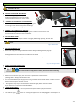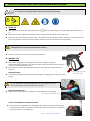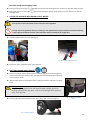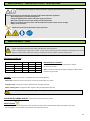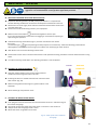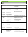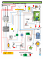
1
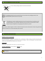
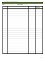
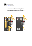
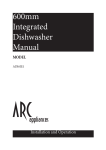
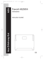
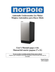
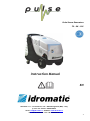
Pulse Steam Generators 7K – 9K – 11K Instruction Manual EN Idromatic s.r.l. - via Petrarca n°127 - 46030 Borgoforte (MN) – Italy p.iva e cod. fiscale: 02096330200 email: [email protected] - website: www.idromatic.it tel. +39 0376 648756 - fax. +39 0376 649140 1 PREFACE Please read and comply with these original instructions prior to the initial operation of your appliance as to avoid improper or dangers operations to persons, animals or objects during use. Store this manual near the appliance and in a safe place for future reference. - Before first start-up it is definitely necessary to read the operating instructions and the safety indications In case of transport damage inform vendor immediately Check the contents of the pack before unpacking PULSE is a professional mobile steam generator for indoor or outdoor use suitable for cleaning of surfaces and sanitization where large amounts of water are not available for use. The use of steam cleaner is subject to valid national regulations. Besides the operating instructions and the binding accident prevention regulations valid in the country of use, observe recognized regulations for safety and proper use. Do not use any unsafe work techniques. WARNING! The manufacturer is not responsible for and reserves the right to not apply the warranty to: Damage caused by normal wear and tear, abnormal use or conditions, misuse, neglect, abuse, accident, improper handling or storage, exposure to moisture, unauthorized modifications, alterations or repairs, improper installation, improper use of any electrical source, undue physical or electrical stress, operator error, non-compliance with instructions or other acts which are not the fault of manufacturer, including damage or loss during shipment. Certified Product Made in Italy 2 CONTENTS SYMBOLS USED 3 ENVIRONMENTAL PROTECTION 4 GENERAL DESCRIPTION 4-5-6 TECHNICAL SPECIFICATIONS 7 SAFETY INSTRUCTIONS 8-9-10 PRELIMINARY OPERATIONS 11 START UP, OPERATIONS, SHUTTING DOWN AND STORAGE 12-13 MAINTENANCE - IMPORTANTS SAFETY REGULATIONS 14 MAINTENANCE - PLAN 14 MAINTENANCE - DESCALING 15 TROUBLESHOOTING 16 WIRING DIAGRAM 17 HYDRAULIC DIAGRAM 18 CONDITIONS OF WARRANTY 19 CONFORMITY DECLARATION 20 SYMBOLS USED Instruction manual Attention – Risk - Danger Electrical risk Read manual Hot surface – risk of scaldings Attention corrosive substances Earth connection Wear protective gloves High-pressure jets can be dangerous if improperly used. The jet may not be directed at persons, animals, live electrical equipment or at the appliance itself. Wear ear plugs Steam – Burning danger Wear safety goggles Dispose old appliances using appropriate collection system Unplug the appliance Authorized maintenance Contamination hazard 3 ENVIRONMENTAL PROTECTION Do not release packing materials into the environment. The packaging material can be recycled. Please do not throw the packaging material into household waste; please send it for recycling Old appliances contain valuable materials that can be recycled; these should be sent for recycling. Batteries, oil, and similar substances must not enter the environment. Please dispose of your old appliances using appropriate collection systems. Please do not release engine oil, fuel oil, diesel and petrol into the environment. Protect the ground and dispose of used oil in an environmentally-clean manner. GENERAL DESCRIPTION PROPER USE OF THE APPLIANCE Pulse steam generator is designed for professional use, in particular for carwash, cleaning of surfaces and working tools, operations of sanitizing ,degreasing and rust removing with the possibility to inject correct detergents mixed with dry steam. Please always comply with these instructions for a correct use. TRANSPORT Always use the original pallet to move and carry on vehicles the machine. PACKAGE DIMENSION: 92 X 61 X 85 CM WEIGHT: 65 kg Check the contents of the pack before unpacking. In case of transport damage or missing components inform vendor immediately 4 MAIN COMPONENTS 11 7 5 6 12 1 8 4 3 9 2 10 Fig. 2 Fig. 1 1) 2) 3) 4) 5) 6) Water tank Boiler blow down valve Steam outlet Steam regulation knob Detergent tank Pressure gauge 7) 8) 9) 10) 11) 12) Hour meter Steam hose supports Technical data - Serial number Wheels with brake Front cover Rear cover CONTROLS AND INDICATOR LIGHTS main switch ON/OFF Power supply lamp State Machine ON Steam out switch ON/OFF Fig. 3 Alarm lamp Water shortage lamp Detergent shortage lamp Fig. 4 5 STANDARD EQUIPMENT Instruction Manual 1.Steam gun with control M22 2. Detailing nozzle teflon 120mm 3. Steam hose 10m (1pz) 4. Microfiber cloth (1pz) 5. Water softening filter with polyphosphate granules (inside) 6. Descaling monodose (100cc) 1 4 3 2 6 5 Fig. 5.a OPTIONAL EQUIPMENT 1. Connection to mains supply water 2. Detergent/water selector 3. Descaling solution (10Lt) 4. Polyphosphate granules (1,5kg) 5. Protective gloves 6. Nylon brush 7. Small lance 280 mm 8. Extension lance 600-900-1200-2000 mm 9. Brass brush 10. Window cleaning tool 1 7 3 2 4 5 9 8 6 10 Fig. 5.b 6 TECHNICAL SPECIFICATIONS The technical specifications are written in the metal plaque as shown (Fig.6) as well as the serial number of the machine which will identify them uniquely. Fig. 6 These serial numbers must be given to the reseller or the manufacturer as well whenever assistance is requested for the steam cleaner. Model Pulse 7K Power Supply [V] Pulse 9K Pulse 11K 380/400V ; 3~ ; 50/60 Hz Power [W] Fuses [A] Steam production [kg/h] Detergent flow-rate [L/min] 7000 9000 11000 12 16 16 11.5 13.5 17.8 0.15 Pressure [bar] 10 Steam temp. [°C] 180 Boiler [L] 8 Water tank [L] 30 Detergent tank [L] 10 Detergent Temperature [°C] 90-125 Boiler material AISI 304 Heating elements Flanged - Incoloy 800 Frame material Polyethylene high density Protection grade IP X5 Insulation class I Power cable Hand Vibration Sound Pressure [dBA] ] < 2.5 88 Remote Control 2.4GHz, point to point Dimensions [cm] 92 X 61 X 85 Weight [kg] 65 7 SAFETY INSTRUCTIONS Please read and comply with these safety instructions prior to the initial operation of your appliance. Keep these safety instructions for use for future reference or for subsequent possessors. Warning and information plates on the machine provide important directions for safe operation Apart from the notes contained herein the general safety provisions and rules for the prevention of accidents of the legislator must be observed. Keep packaging film away from children to eliminate risk of suffocation. POWER CONNECTION - The voltage indicated on the type plate must correspond to the voltage of the electrical source - Minimum fuse strenght of the socket ( See Technical Data) - Safety class I – Appliances may only be connected to sockets with proper earthing - It is recommended that the electric supply to this machine should include either a residual current device that will interrupt the supply if the leakage current to earth exceeds 30mA for 30ms or a device which will prove the earth circuit - Please use the mains cable prescribed by the manufacturer; the same is also when you replace the cables inside the machine - Check the power cord with mains plug for damage before each use. If the power cord is damaged, please arrange immediately for the exchange by an authorized customer service or a skilled electrician. - The appliance may only be connected to an electrical supply which has been installed by an electrician in accordance with IEC 60364-1. - Operating procedures create short term power sinkings. - During unfavorable net conditions other devices might be disturbed - With a net impedance lower then 0.15 Ohm no disturbances are to be expected. - Never touch the mains plug with wet hands. - Make sure that the power cord or extensions cables are not damaged by running over, pinching, dragging or similar. Protect the cable from heat, oil, and sharp edges. - The mains plug and the coupling of an extension cable must be watertight and must never lie in water. Moreover, the coupling must never lie on the ground. The use of cables reels that ensure that the sockets are at least 60 mm above the ground is recommended - Unsuitable extensions cables can be hazardous. Only use extension cables outdoors which have been approved for this purpose and labelled with a sufficient cable cross-section. The power cord must be checked regularly for damages, such as cracks or aging. If damage is found, the cable must be replaced before further use. - When replacing couplings on the power cord or extension cable, the water tightness and the mechanical resistance must remain ensured. Do not clean the appliance with a water hose or high pressure jet (danger of short circuits or other damage). Do not operate the appliance at temperatures below 0 ° C. Comply with the shutting down instructions in proper section of this manual. 8 APPLICATION AND OPERATIONS The appliance and its working equipment must be checked to ensure that it is in proper working order and is operating safely prior to use. The appliance must not be used if a connecting line or important parts of the appliance (ex. Safety valves, high temperature hoses, spray guns) are damage. If the appliance is used in hazardous areas (ex. Filling stations) the corresponding safety provisions must be observed. It is not allowed to use the appliance in hazardous locations. The appliance must be sitting on an even stable ground. Wear ear plugs if the technical data mention a noise level of more than 80 dB (A). All current-conducting parts in the working area must be protected against water jet. The trigger on the hand spray gun must not be locked during the operation. Wear protective clothing and safety goggles to protect against splash back containing water or dirt. High-pressure jets can be dangerous if improperly used. The jet may not be directed at persons, animals, live electrical equipment or at the appliance itself. The jet must not be directed at other persons or directed by the user at him/herself to clean clothing or footwear. Vehicle tyres / tyre valves may be cleaned only with a minimum spray distance of 30 cm. Otherwise, the high pressure spray can cause damage to the vehile tyre / tyre valves. The discolouring of the tyre is the first sign of damage. Damaged vehicle tyres are source of danger. Do not spray materials containing asbestos or other health-hazardous substances With short spray lances, there is a risk of injury, as a hand can accidentally come in contact with the high pressure jet. If the spray lance in shorter than 75 cm you must not use a point spray nozzle or a rotating nozzle When using detergents , the material data safety sheet issued by the detergent manufacturer must be adhered to, especially the instructions regarding personal protective equipment. Prior to cleaning, a risk assessment must be performed for the surface to be cleaned to determine the safety and health requirements. The respective required protective measures must be taken. Use only those detergents approved by the manufacturer of the appliance. This appliance was designed to be used with detergents which are supplied or recommended by the manufacturer. The use of other detergents or chemicals may compromise the safety of the appliance. Do not use the recommended detergents in an undiluted state. The products are safe for operations as they do not contain any environment hazardous substances. If the detergent comes in contact with the eyes, please rinse the eyes thoroughly with water and consult a doctor immediately if the detergent has been swallowed. Store detergents away from the reach of children In case of extended downtimes, switch the appliance off at the main switch/ appliance switch or remove the mains plug Do not open covers if the appliance is running. The water that passes through the appliance is no longer considered fit for drinking. In case of connection to water network a backflow device has to be installed. With connection to mains supply water please follow the local regulations. It is recommend to use water supply less than 6 bar to avoid damages to internal parts. 9 The operator must use the appliance properly. The person must consider the local conditions and must pay attention to third parties, in particular children, when working with the appliance. Never leave the appliance unattended so long as it is running. The appliance may only be used by persons who have been instructed in handling the appliance or have proven qualification and expertise in operating the appliance or have been explicitly assigned the task of handling the appliance. The appliance must not be operated by children, young persons or persons who have not been instructed accordingly. This appliance is not intended for use by persons with reduced physical , sensory or mental capabilities. Do not open covers if the appliance is running. Children should be supervised to prevent them from playing with the appliance. Do not use the appliance nearby people unless they wear personal protective clothing. Hold trigger gun and accessories firmly. MAINTENANCE AND SPARE PARTS Switch off the appliance and , in case of appliances connected to the mains, pull out the power cord before cleaning and performing any maintenance tasks on the machine Relieve the high pressure system of all pressure prior to all work on the appliance and the accessories Maintenance work may only be carried out by approved customer service outlets or experts in this field who are familiar with the respective safety regulations. Mobile industrial appliances are subject to safety inspections according to the local regulations To prevent any case of accidents substitutions of components have to be done by authorized personnel Only use original spare parts and components. If not the safety of the appliance may be compromised SAFETY DEVICES This steam cleaner is equipped with several safety devices the provide a complete protection of the appliance. The most important safety devices are described in the following: Pressure controller: the pressure controller keeps the boiler between 9 to 10 bar Automatic reset thermostat: if the temperature of the steam reaches 185°C the device cuts off the heating elements. Manual reset safety thermostat: if the temperature of the boiler exceeds 230°C the machine stops working Safety valve: it prevents overpressure inside the boiler. The safety valve is set up at 11 bar Boiler level safe-guard: if during normal use the water pump runs more than 1 minute the machine stops and alarm light keeps blinking. Water level control: the water probe sensor outside the boiler keeps regular and constant refilling of water. 10 PRELIMINARY OPERATIONS The manufacturer is not responsible for any damage caused by improper handling or non compliance with these instructions for use a. SECURE THE MACHINE WITH BRAKE: Before initiating any operation, position the appliance on a firm and stable surface and secure the brake of rear wheel. b. CONNECT THE STEAM HOSE TO THE MACHINE: Connect the steam hose to the coupling tightening the nut using a 17mm wrench and protect the fittings with the burning protection.(Fig.8) Fig. 7 – Brake Fig. 8 – Steam hose connection c. CONNECT THE STEAM GUN TO THE HOSE: Attach the steam-gun to the hose tightening the nut with a 17mm wrench and protect the fittings with the burning protection. team hose connection team hose connection d. FILL THE WATER TANK: Refill the water tank through the water inlet (Fig.9) with enough quantity, at least 10 lt. Use clean water supply, softened but non distilled. It’ po ible to use demineralized water. Fig. 9 – Water inlet e. FILL THE DETERGENT TANK: Read and comply the detergent datasheet before filling the detergent tank (Fig.10). Detergents have to be suitable for the surface to be cleaned It is possible to refill the detergent tank with water for hot water injection mixed with steam. Fig. 10 – Detergent inlet f. VERIFY THE POWER CONNECTION: It is recommend to comply with the safety instructions before initiating. Make sure the electric supply has the electric specifications of the machine (Voltage-Power –Amps). Read technical data. It is recommended that the electric supply to this machine should include either a residual current device that will interrupt the supply if the leakage current to earth exceeds 30mA for 30ms or a device which will prove the earth circuit. The appliance may only be connected to an electrical supply which has been installed by an electrician in accordance with IEC 60364-1. g. PLUG THE APPLIANCE : Make sure the switches on control panel are OFF position before plug the machine . The indicator light turns on meaning the appliance is correctly plugged in and ready for use. 11 START UP, OPERATIONS , SHUTTING DOWN AND STORAGE It is recommend to comply with the safety instructions before initiating. a. START UP: Open the steam solenoid valve pushing the button on control panel (Fig.3). The green light of the button will turn on. Make sure the steam regulation knob (Fig.1) is open and the boiler blow down valve (Fig.2) closed Rotate the main switch (fig.3) from OFF to ON. The appliance will start filling the boiler with water and during this time the alarm light will be ON. Then when the water reaches the correct level the boiler will start heating. Keep trigger gun open while water pump is running and for the first few minutes of heating. This operation discharges the air and condensate inside boiler and hose . The boiler takes about 5 minutes to produce the first steam. b. NORMAL USE : Keep open the trigger gun to discharge dry steam and for regular use (Fig.11). Always follow safety indications regarding use of the machine and make sure the steam jet is 10cm from the surface to be clean . During regular use Pulse will automatically maintain the boiler water level and pressure constant . DETERGENT MODE: To activate the detergent pump keep pushing the button on trigger gun as long as you need (Fig.11) Fig. 11 –Trigger gun with detergent control It is recommended to activate the detergent only when trigger gun is open. This avoids detergent coming back into hose and boiler. DRY STEAM REGULATION : Regulate the dry steam flow rate rotating the steam regulation knob (Fig.12). Fig. 12 –Steam regulation knob USE OF THE DEGERGENT OR WATER SELECTOR : If the machine is equipped with the detergent/water selector mounted on panel (Fig.13), rotate the lever to select the product to mix with the steam. The injection is activated by pushing the button on the trigger gun. Fig. 13 – Detergent/water selector 12 REFILLING WATER AND DETERGENT TANKS : During normal use if the light During the normal use if the light detergent tank. goes ON the machine stops working and it is necessary to refill with water the tank. goes ON the detergent injection stops working and it is necessary to refill the c. USE OF THE APPLIACE WITH MAINS SUPPLY WATER Be sure the water mains pressure is less than 6 bars. Internal components as filters can be damaged. If the supply water pressure is more than 6 bar use the water tank of the appliance. Comply with local regulations about your water grid. The appliance may only be connected to the mains drinking water supply if a backflow preventer valve with drain facility is installed in the supply hose. Remove front cover and turn the 3 way selector to the position shown in Fig.14 Connect supply water hose to the inlet (Fig.15) Fig.14 – 3way selector Fig.15 – Mains supply water inlet Close front cover and follow regular use indications d. SHUTTING DOWN AND STORAGE: When work is finished turn off the machine and discharge the steam with trigger gun until the boiler pressure reaches 0 bar. The operation of discharge the steam prevents scales inside the boiler. After finishing pressure discharge the boiler unplug the machine and store in a safety place. Frost Protection: If the machine is stored in areas with temperatures 0° C / 32 F make sure to discharge the boiler with the blow down valve.(Fig.16) and to discharge also water tank and filters. Frost can cause damages to the appliance and to its components to discharge water tank dismount the tap with hand or with 17 wrench (Fig.17). Fig. 16 –Boiler blow down valve Fig. 16 –Boiler blow down valve Fig. 17 –Water tank tap 13 MAINTENANCE – IMPORTANT SAFETY REGULATIONS It is recommend to comply the safety instructions reguarding maintenance before initiating. Please before starting any maintenance operations follow these important regulations: Wear safety gloves to prevent burning hazard Unplug the appliance from electric and water supply connections Wait 1 hour after the last use of the machine or boiler blow down Make sure the boiler pressure is 0 bar and the temperature of the surfaces are not too high Always use correct tools Maintenance to be done by qualified or expert personnel MAINTENANCE - PLAN A good maintenance always means safety and efficiency of the appliance! Pulse is equipped with a digital hour meter on the control panel (Fig.2) which indicates the working hours of the appliance. Always refer to the hour meter to maintenance of boiler, filters and other components. DESCALING INTERVALS Degree of hardness I soft II medium III hard IV very hard ° dH 0- 7 7-14 14-21 >21 mmol/l 0-1,3 1,3-2,5 2,5-3,8 >3,8 Hours 80 50 35 25 WATER QUALITY CONTROL If you are using hard water it is compulsory to follow the intervals on table. Note: Contact the local water supply company to inquire about hardness of your water FILTERS: The steam generator is equipped with these following filters: Water filter: Check and clean every 20 hrs. Clean with compressed air or water. Detergent filter: Check every 20 hrs. Substitute the cartridge if too dirt Water softening filter: recharge the filter regularly with polyphosphates granules Make sure all filters are properly well tighten after any operations of maintenance BOILER WATER PROBE SENSOR: Check and clean every 20 hours of work SAFETY VALVE: Because of the extreme importance of this component make sure to substitute the safety valve after 2 years from purchasing date. This operation shall be done from authorized service. 14 MAINTENACE - DESCALING It is compulsory to use safety gloves and protection for eyes because descaling products can be aggressive. It is recommended to use only products approved by Idromatic. a. DESCALING PROCEDURE WITH PUMP RECIRCULATION Prepare the descaling solution (10-20%) with proper diluition in a separate tank Use the descaling mondose for mesurement and keep the monodose for next uses. Remove the rear cover (Fig.2) of the machine and disconnect the water suction hose from the water tank. Put the hose inside the descaling solution you’ve prepared . Make sure the steam button is ON and the regulation valve is open. If you intend to descale also steam hose and trigger gun remember to keep the gun open during this operation. Fig. 17 – Cleaning switch Activate the cleaning mode switch (Fig.17) and then turn ON the main switch from O to I. The indicator light will keep blinking and the pump will run continuously . When the descaling product will be discharged from the outlet (or from the gun) turn off the main switch (Fig.3) of the machine. Wait about 2 hours to let the descaling solution work. Put the water suction hose in the tank of the machine and repeat the cleaning procedure to cleanse the boiler with running water. Turn off the cleaning mode switch. The descaling procedure is now completed. GASKET b. CLEANING THE HEATING ELEMENTS HEATING ELEMENTS Open the metal protection cover of the heating elements and dismount the flange bolts with 17 wrench. If heating elements are coated with excessive scale clean them with a bristle. (Fig. 18) Make sure the gasket of the flange is in good condition. If not substitute. Mount the flange and protection cover. c. Fig. 18 – Heating elements CLEANING THE BOILER PROBE SENSOR: First uplug the connector then with 22 wrench dismount the sensor indicated in Fig.19 from boiler level gauge Use a brush to clean the metal part of the sensor in case there’s lime scale on it Verify that also the level gauge inside is clean. Mount the sensor using teflon and connect. Fig. 19 – Water probe sensor and boiler level gauge 15 TROUBLESHOOTING Please read carefully safety instructions concerning maintenance before any kind of operation Problem Meaning Possible resolution No power -faulty electrical connection - check power cord - check plug connection - check fuses inside the box - if the problem persists contact authorized service No/low steam -Steam button on panel OFF -Regulation valve close -Scale inside boiler - Activate the steam controls - Perform descaling - Check fuses in control box Steam too wet / condensate No / low detergent injection The boiler stops heating Water pumps always on Pressure rises but no steam Steam coming out under the machine Long pre-heating time -Boiler not ready -Steam hose not ready -detergent tank is empty -Air inside detergent suction -Detergent filter is dirt -dirt inside detergent pump - Wait until the boiler reaches the pressure - Wait until the steam hose reaches the temperature - Refill the detergent tank -Substitute the detergent filter -Open the valve on detergent pump to discharge the air -Use compressed air to clean inside the detergent pump -check safety thermostat -Over temperature / safety thermostat -discharge the air -wait for the thermostat returns normally closed - if the problem persists contact authorized service -Water probe sensore dirt -Air in pump suction -Water filter dirt -faulty sensor grounding -Boiler not ready -Air inside the boiler -Overpressure / Safety valve -Scale on heating elements -Missing phase -Dirt inside the boiler -dismount and clean the probe sensor -clean water filter with running water or compressed air -check if filter is well tighten -check electronic ground -Open steam regulation valve and trigger gun to discharge the air -Check pressure controller settings -Check safety valve integrity - if the problem persists contact authorized service . -Perform descaling procedure -Check fuses -Open heating elements flange and remove the dirt 16 WIRING DIAGRAM 17 HYDRAULIC DIAGRAM 18 CONDITIONS OF WARRANTY For any request regarding warranty coverage the purchaser must give IDROMATIC the serial number of the unit in question. The warranty is limited to the supply or repair of parts or material we acknowledge to be faulty. 1. The customer must present proof of malfunction and/or faulty parts in question. 2. All faulty parts are to be returned free to our factory unless instructed otherwise. 3. In case of warranty interventions to be made at the purchaser's address, all charges as to trips, transfers and labour are to be sustained by the purchaser. 4. The warranty does not cover electric motors, electronic equipment and accessories. Warranty does not cover the following: 1. Damages due to unauthorized tampering, modification and/or repair by third parties. 2. Damages due to unsuitable use not in compliance with the user manual. 3. Damages due to acts of God or any events beyond the control of Idromatic (ex. damages due to extreme weather conditions or use of non-conformal water as described in this manual). 4. Wear and tear due to normal use and handling. 5. Damages during transport/shipment. IDROMATIC warranty will be void if the client does not honor payments. Any further dispute regarding warranty does not in any way exempt the client from fulfilling payments. 19 Via Petrarca, 127 - 46030 Borgoforte (MN) ITALY Tel. +39 0376 648756 - Fax +39 0376 649140 e-mail: [email protected] Web: http://www.idromatic.it REA MN-223709 / C.F. / P.Iva IT 02096330200 Cap. Soc. € 65.000,00 i.v. EC DECLARATION OF CONFORMITY Name and postal address of manufacturer: IDROMATIC S.r.l. Via F. Petrarca 127 46030 BORGOFORTE (MN) ITALY Idromatic declares that the design of the appliance described below Product: Electric steam cleaner Model : Pulse 7K ; Pulse 9K ; Pulse 11K Description: 380/400V ; 3~ ; 50/60 Hz ; 7000W 380/400V ; 3~ ; 50/60 Hz ; 9000W 380/400V ; 3~ ; 50/60 Hz ; 11000W Complies with the following regulations : 2006/42/EC – Safety Machinery directive 2006/95/EC – Low Voltage directive 2004/108/EC – Electromagnetic compatibility directive 2002/95/EC – Restriction of hazardous substances directive Applied harmonized standards: EN 12100-1 EN 12100-2 EN 60335-2-79 EN 60204-1 EN 55014-1 EN 55014-2 EN 6100-3-2 EN 61000-3-3 Borgoforte, 01/11/2013 Signature of the legal representative 20 MAINTENANCE OPERATIONS MODEL: ……………………………………………. SERIAL NUMBER…………………… DATE DESCRIPTION OF INTERVENTION WORKING HOURS OPERATOR SIGNATURE ………………… …………………………………………………………………………………………… ………………………….. …………………………… …………………. …………………………………………………………………………………………… ………………………….. …………………………… …………………. ………………………………………………………………………………………….. ………………………….. …………………………… …………………. ………………………………………………………………………………………….. ………………………….. …………………………… …………………. ………………………………………………………………………………………….. ………………………….. …………………………… …………………. ………………………………………………………………………………………….. ………………………….. …………………………… …………………. ………………………………………………………………………………………….. ………………………….. …………………………… …………………. ………………………………………………………………………………………….. ………………………….. …………………………… …………………. ………………………………………………………………………………………….. ………………………….. …………………………… …………………. ………………………………………………………………………………………….. ………………………….. …………………………… …………………. ………………………………………………………………………………………….. ………………………….. …………………………… …………………. ………………………………………………………………………………………….. ………………………….. …………………………… …………………. ………………………………………………………………………………………….. ………………………….. …………………………… …………………. ………………………………………………………………………………………….. ………………………….. …………………………… …………………. ………………………………………………………………………………………….. ………………………….. …………………………… …………………. ………………………………………………………………………………………….. ………………………….. …………………………… …………………. ………………………………………………………………………………………….. ………………………….. …………………………… …………………. ………………………………………………………………………………………….. ………………………….. …………………………… …………………. ………………………………………………………………………………………….. ………………………….. …………………………… …………………. ………………………………………………………………………………………….. ………………………….. …………………………… …………………. ………………………………………………………………………………………….. ………………………….. …………………………… …………………. ………………………………………………………………………………………….. ………………………….. …………………………… ………………. ………………………………………………………………………………………….. ………………………….. …………………………… 21 22