1
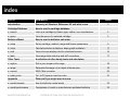
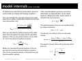
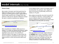
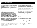
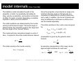
Revised
August 2014
PRACTICE SAFE FIREARMS HANDLING AND FOLLOW ALL SAFETY RULES!
index
TOPIC
SUMMARY
Introduction
Summary of Shooter’s Reference V3 and what’s new
Cartridge Database
How to use the cartridge database
● search
Look up a cartridge by firearm type, caliber, use, manufacturer
4
● specs
View the specs of a selected cartridge
5
Ballistics Model
How to use the ballistics calculator
● setup
Set up cartridge, ambient, range and firearm parameters
6
● solve
Calculate solution at distance, bearing and inclination
11
● hold
View mil scope display hold for calculated solution
16
● table
View range table with drop and drift corrections
17
Other Tools
A collection of other handy tools and calculators
● sight-in
Dial in your scope on the range
18
● range
Determine the range of an object of known size
19
● convert
MOA / Mils converter
20
● safety rules
Col. Jeff Cooper’s rules four rules
21
Appendix
Other stuff you might want to know
● model internals
How the ballistics model works
23
● model performance
Comparison of model vs manufacturers published ballistics
33
SHOOTER’S REFERENCE V3
COPYRIGHT © 2014 THIS TIME FOR SURE APPS LLC
PAGE
3
introduction [getting started]
Shooter’s Reference V3 is a ballistics calculator for sports
shooting enthusiasts that features a classical physics-based
projectile motion model, cartridge database, and several other
useful tools.
The V3 ballistics model supports G1 and G7 drag models (as
well as many others), BC (ballistic coefficient) and ambient
weather conditions compensation yielding accurate bullet drop
and wind drift solutions. For ease of use, Shooter’s Reference
has a built-in database of over 2,000 cartridges from Barnes®,
Buffalo Bore®, CCI®, Eley®, Federal Premium®, Fiocchi®,
Hornady®, Norma-USA®, Nosler®, PMC®, Remington®,
Weatherby®, and Winchester®. In addition, the user can
manually enter the required input parameters such as muzzle
velocity and bullet weight.
Additional tools are included that aid sight-in calculations at the
range, estimating the distance to a target, and performing mils
and moa calculations.
Both imperial and metric units are supported.
Contact Us
[email protected]
WARNING!
PRACTICE SAFE FIREARMS
HANDLING AND FOLLOW ALL
SAFETY RULES!
ALWAYS!!!
Comments, complaints, suggestions, and questions are
appreciated.
SHOOTER’S REFERENCE V3
COPYRIGHT © 2014 THIS TIME FOR SURE APPS LLC
3
search [find your cartridge’s specs in the built-in database]
Cartridge Database
In order to set up the ballistics calculator, there are a few
parameters you need to know about your cartridge. We have
included a database of over 2,600 popular rifle and handgun
cartridges that can be searched simply by tapping the search
boxes on the search page. Tap the products box to see the
list of cartridges that match your criteria and to choose one.
Note that a maximum of 100 products can be displayed. The
best way to avoid that limit is to choose a cartridge.
The parameters required by the ballistics calculator are
automatically loaded into the setup page when a product is
selected. The following parameters are extracted:
Bullet diameter
Bullet weight
Ballistic coefficient (optional, not required)
Muzzle velocity
Muzzle energy (not used, but displayed)
SHOOTER’S REFERENCE V3
COPYRIGHT © 2014 THIS TIME FOR SURE APPS LLC
4
specs [view manufacture’s data and description]
Cartridge Specs
When a cartridge is selected from the database, a summary of
the its specifications is displayed on the specs page. The
specs are from the manufacturer and are subject to change.
Typically, the following specifications are available:
Manufacturer, product line, and part number
Cartridge and bullet description
Typical application
Bullet weight and ballistic coefficient
Muzzle velocity
Muzzle energy
SHOOTER’S REFERENCE V3
COPYRIGHT © 2014 THIS TIME FOR SURE APPS LLC
5
setup [setup model parameters]
Model Setup
Cartridge and Bullet Parameters
These parameters describe the cartridge and bullet.
bullet caliber
► Required, inches or mm, depending common usage
bullet weight
► Required, always in grains
ballistic coefficient
► Only required if use bc box is checked
► Default is to not use BC in ballistics model (yields best
results)
► Can be applied to any of the bullet models but most
manufacturers only specify a G1 BC
bullet model
► Required, G7 default
► G7 works best for low drag bullets
► See page 30, Standard Bullet Models for more
information
SHOOTER’S REFERENCE V3
COPYRIGHT © 2014 THIS TIME FOR SURE APPS LLC
6
setup [setup model parameters]
Model Setup (continued)
Cartridge and Bullet Parameters (continued)
use bc
► Not required or recommended
► If checked, ballistics model applies BC to selected bullet
model’s drag coefficient
muzzle velocity
► Required, in fps or mps
muzzle energy
► Displayed for information only, in ft-lbs or Joules
SHOOTER’S REFERENCE V3
COPYRIGHT © 2014 THIS TIME FOR SURE APPS LLC
7
setup [setup model parameters]
Model Setup (continued)
Ambient Conditions
Entering ambient conditions allow Shooter’s Reference to
calculate wind drift corrections as well as air density
compensation. U.S. Army Standard Metro conditions are the
default.
wind speed
► Optional, in mph or kph
wind direction
► Optional, in degrees, using meteorological convention
(see illustration on page 13)
elevation
► Optional, in feet or meters above sea level)
► If zero, temperature, humidity and pressure are
used to calculate air density (most accurate method)
► If non-zero, then altitude is used to calculate air density
(better than no air density correction)
SHOOTER’S REFERENCE V3
COPYRIGHT © 2014 THIS TIME FOR SURE APPS LLC
8
setup [setup model parameters]
Model Setup (continued)
Ambient Conditions (continued)
temperature
► Optional, in degrees Fahrenheit or Celsius
humidity
► Optional, in RH percent
pressure
► Optional, in inches of Mercury or hectoPascals
Tip: If exact ambient conditions are not available,
a good guess at temperature and humidity while
leaving the pressure at the default value will
improve the ballistic model’s results.
SHOOTER’S REFERENCE V3
COPYRIGHT © 2014 THIS TIME FOR SURE APPS LLC
9
setup [setup model parameters]
Model Setup (continued)
Firearm Setup
The model uses the scope mounting height and the zero
distance to calculate the bore angle of the firearm relative to the
line of sight. The centerline to centerline height of the scope
relative to the barrel is critical to the accuracy of the model.
scope height
► The centerline to centerline height of the scope or sights
to the barrel
► Required, in inches or millimeters
zero distance
► Required, in yards or meters
Measurement Units
Metric units are used internally. Input and display units can be
toggled at any time by checking/unchecking this box.
input units
► Required, in yards or meters
SHOOTER’S REFERENCE V3
COPYRIGHT © 2014 THIS TIME FOR SURE APPS LLC
10
solve [enter target data and solve model]
Find a Solution
The target distance, bearing, and inclination angle are entered
on the solve page. Press the solve button to calculate the
solution.
distance
► The line of sight distance to the target
► Required, in yards or meters
bearing
► The target bearing
► Required, in degrees
inclination angle
► The target inclination angle (see illustration on page 13)
► Required, in degrees
The line of sight distance (also referred to as the slant range) is
the straight line distance as measured to the target. The
ballistics model uses the Rifleman’s Rule to calculate the
horizontal distance to the target. This compensates for uphill or
downhill shooting situations.
SHOOTER’S REFERENCE V3
COPYRIGHT © 2014 THIS TIME FOR SURE APPS LLC
11
solve [enter target data and solve model]
The inclination angle is the angle of the target relative to the
shooter. A 0° inclination is horizontal, flat ground. Positive
inclination angles indicate an uphill shot while negative
inclination angles indicate a downhill shot. Please refer to
Wikipedia for an explanation of the Rifleman’s Rule.
Source: http://en.wikipedia.org/wiki/Rifleman's_rule
SHOOTER’S REFERENCE V3
COPYRIGHT © 2014 THIS TIME FOR SURE APPS LLC
12
solve [enter target data and solve model]
The bearing is the compass bearing of the target.
Wind
Direction
315°
N 0°
Target
Bearing
45°
W 270°
E 90°
Target
Bearing
225°
S 180°
Tip: Target bearing is the direction in which the firearm
is pointing. Wind direction is where the wind is blowing
from (meteorological convention).
SHOOTER’S REFERENCE V3
COPYRIGHT © 2014 THIS TIME FOR SURE APPS LLC
13
solve [enter target data and solve model]
Click the solve button to calculate the solution.
Drop and drift are displayed in length units as well as mils and
MOA’s. “U” and “D” preceding a number refer to up and down while
“L” and “R” preceding a number refer to left and right sight
adjustments.
For example, in the screenshot to the right, the sights should be
adjusted up 2.7 MOA or 0.8 mils to account for bullet drop. 2.6 MOA
or 0.4 mils left must be dialed-in to account for wind drift.
The kinetic energy and bullet velocity at the target distance are also
displayed. Kinetic energy is displayed in either ft-lb or Joules.
Velocity is displayed in feet per second (fps) or meters per second
(mps).
Bore Laser Sight
The laser bore sight solution displays the two key numbers required
to sight-in a firearm at a desired zero distance when using a bore
laser light such as the SITELITE® Mag Laser Boresighters ®.
The laser / LOS intercept is the distance at which the bore laser line
and the line of sight cross. It is displayed in yards or meters. If you
place a target at this distance, the laser dot on the target should be
right in the center of the scope or on the front sight.
SHOOTER’S REFERENCE V3
COPYRIGHT © 2014 THIS TIME FOR SURE APPS LLC
14
solve [enter target data and solve model]
The laser position on target is the distance from the sight
position to the laser dot on the target required to achieve the
desired zero distance. The target distance is the value entered
for distance under target parameters.
Tip: In addition to the target distance, the bore sight
calculator requires the ballistics of the cartridge in use and
the mounting height of the scope or sights. The cartridge
ballistic specs can be manually entered in the setup page
or by selecting a cartridge in the search page. Consult
your laser bore sight manufacturer’s user’s manual for
instructions specific to your model.
SHOOTER’S REFERENCE V3
COPYRIGHT © 2014 THIS TIME FOR SURE APPS LLC
15
hold [sight picture]
Mil-Dot Sight Picture
Once a solution is found, the hold page displays the “hold”
position required to be on target at the distance, bearing, and
inclination angle entered on the solve page. Holding the
firearm such that the target is in the position indicated by the
green dot, will place the shot on the target.
The vertical axis is labeled in half mil-dot increments with the ontarget distances corresponding to that vertical hold. The
horizontal axis is also labeled in half mil-dot increments with the
distances corresponding to wind drift.
For example, a 350 yard shot would require a vertical hold of
just under 1 mil (352 yards) for drop and about 0.7 mils (0.7 x
500 yards) for wind drift.
When metric units are selected, sight picture values are
displayed in meters.
SHOOTER’S REFERENCE V3
COPYRIGHT © 2014 THIS TIME FOR SURE APPS LLC
16
table [view drop and drift correction table]
Drop and Drift Table
Once a solution is found, the table page displays the drop and
drift solution from 50 to 500 yards or meters at 5 yard or meter
increments at a zero degree inclination angle.
“U” and “D” preceding a number refer to up and down while “L”
and “R” preceding a number refer to left and right sight
adjustments.
SHOOTER’S REFERENCE V3
COPYRIGHT © 2014 THIS TIME FOR SURE APPS LLC
17
sight-in [sight-in your rifle at the range]
Sighting-in on the Range
The sight-in page provides a simple, non-model method of
zeroing a firearm on the range.
target distance
► Required, in yards or meters
vertical adjustment
► Required, in inches or centimeters
► The vertical distance to move the impact point. Enter a
positive value to move the impact point up, a negative
value to move the impact point down.
horizontal adjustment
► Required, in inches or centimeters
► The horizontal distance to move the impact point. Enter a
positive value to move the impact point right, a negative
value to move the impact point left.
Tip: Use 3-5 rounds and average the distance from the
target center for best results.
SHOOTER’S REFERENCE V3
COPYRIGHT © 2014 THIS TIME FOR SURE APPS LLC
18
range [estimate target range using mil scope]
Estimating Range Using a Mil/MOA Scope
The range page provides a simple method of estimating the
range of a target given its actual size and apparent size in mils
or MOA.
actual size
► Required, in inches or centimeters
► The actual height of the target area being measured
scope size
► Required, in mils or MOA
► The apparent height of the target area being measured
scope units
► Required, choose mils or MOA
► Determines table increment display
table increment
► Required, choose 1/8th or 1/10th increments
► Determines range table increment display
SHOOTER’S REFERENCE V3
COPYRIGHT © 2014 THIS TIME FOR SURE APPS LLC
19
convert [convert distances to mils and moa]
Converting Mils or MOA
The convert page provides a simple calculator to determine
the value of Mils or MOA’s at a given distance.
distance
► Required, in yards or meters
► The target distance
The value of both a Mil and MOA (or quarter fractions) is
displayed in inches or centimeters.
SHOOTER’S REFERENCE V3
COPYRIGHT © 2014 THIS TIME FOR SURE APPS LLC
20
safety rules [read them. learn them. live them.]
Lt. Col. Jeff Cooper (USMC), founder of Gunsite Academy,
author, columnist, professor, WW II and Korean War combat
veteran, and innovator of the Modern Technique of the Pistol
had four simple safety rules:
ALL FIREARMS ARE ALWAYS LOADED
NEVER LET THE MUZZLE OF A FIREARM POINT
ANYTHING YOU ARE NOT WILLING TO DESTROY
KEEP YOUR FINGER OFF THE TRIGGER UNTIL YOUR
SIGHTS ARE ON THE TARGET
BE SURE OF YOUR TARGET
THE IMPORTANCE OF THESE RULES CAN NOT BE STRESSED
ENOUGH. THE MOST IMPORTANT SAFETY FEATURE WHEN
HANDLING A FIREARM IS THE ONE BETWEEN YOUR EARS,
NOT THE ONES ON THE FIREARM.
SHOOTER’S REFERENCE V3
COPYRIGHT © 2014 THIS TIME FOR SURE APPS LLC
21
APPENDIX
Model internals
Model performance
model internals [how it works]
Shooter’s Reference’s ballistics model is based on
Newtonian physics. This section describes the inner
workings of the model in mathematical terms. Basic
knowledge of physics and calculus is required to
understand the model but is not a prerequisite for
using the application. Several good books available
as well as Wikipedia’s articles on external ballistics
and related topics as well as many other Internet
sources. Our preferred source is Bryan Litz’s
excellent book.
Litz, Bryan (2011), Applied Ballistics for Long Range
Shooting (2nd edition), Cedar Springs, MI, Applied
Ballistics LLC.
The ballistics model can be divided into three
functional blocks.
Ambient Conditions
Firearm Setup
Projectile Motion Simulation
SHOOTER’S REFERENCE V3
Ambient Conditions
There are three factors that are important to
calculating an accurate trajectory: air density, the
speed of sound, and crosswind speed.
Air density can be calculated one of two ways by
the model. The preferred method is to use
temperature, pressure and humidity at the
shooter’s location. Alternatively, the model can
use elevation and sea level temperature, pressure
and humidity or their approximation. In reality, for
hunting distances out to 500 yards, air density is a
very small factor in bullet drop or drift, typically on
the order of tenths of an inch. By comparison, we
see several inches of variation when comparing
trajectories generated by utilizing the G7 model
instead of the G1+BC model (see comparisons in
Appendix).
COPYRIGHT © 2014 THIS TIME FOR SURE APPS LLC
23
model internals [how it works]
To determine air density from temperature, pressure
and humidity we employ the following equations:
First, we calculate the saturation pressure for water
vapor from a rather complicated magical formula that
uses temperature only.
.
=
= −
Next, we calculate the partial pressure of the water
vapor from the relative humidity and the saturation
pressure. This is a very small number, on the order
of 1-2% of the total atmospheric pressure.
=
100
×
The density of a mixture of dry air and water
follows:
!"#
=
×$
+
×&
×$
The speed of sound varies with air density and is
given by:
Before we calculate the partial pressure of dry air,
we need to know the local atmospheric pressure.
This can be measured directly or obtained from your
favorite weather website.
SHOOTER’S REFERENCE V3
'
The partial pressure of dry air can be determined
by simple subtraction:
.
.
=
If the local atmospheric pressure can not be
determined, an approximation can be made
based on altitude and either actual nearby or
standard sea level pressure.
( = ) ×
COPYRIGHT © 2014 THIS TIME FOR SURE APPS LLC
!"#
24
model internals [how it works]
Firearm Setup
Bore angle is the barrel cant that results from the
difference between the line of sight to the target
(what you see through the scope or sights) and the
launch angle required to be on target at the zero
distance on flat ground. Shooter’s Reference allows
the user to choose an arbitrary zero distance.
A zero distance that is close to the target range is
recommended. For example, when targets are
likely to be around 75 yards away, set the zero
distance to 75 yards.
Bore angles are typically very small, around 0.05
to 0.10 degrees. However, a small variation can
result in several inches of error at 500 yards.
Shooter’s Reference calculated zero at the actual
zero distance is ±0.05 inches (±1.27mm).
Source: http://en.wikipedia.org/wiki/Rifleman's_rule
Most manufacturers’ ballistics tables assume a
height of 1.5 inches but chances are that your sights
or scope are not mounted at that height. This is a
significant source of error. The centerline to
centerline height of the sights or scope above the
barrel is required to calculate the bore angle. This
measurement is critical and should be taken with
care.
SHOOTER’S REFERENCE V3
Source: http://en.wikipedia.org/wiki/Rifleman's_rule
The zero distance and scope height entered on
the setup page is used to generate a custom
drop table for your cartridge and firearm. The
ballistics model uses an iterative process that
takes into account the cartridge, bullet and
ambient conditions to determine the bore angle.
COPYRIGHT © 2014 THIS TIME FOR SURE APPS LLC
25
model internals [how it works]
The zero correction in mils and moa is displayed on
the solve page and the bore angle is used by the
ballistics model along with the inclination angle to
generate the solution at the target distance as well
as the custom drop table.
Projectile Motion Simulation
Once the ambient conditions, firearm, and
cartridge/bullet parameters are set, the ballistics
model generates a solution at the user specified
distance on the solve page and for each distance
point in the accompanying drop/drift table page.
Bullet drag is calculated using one of two formulas
depending on whether the user has selected the
“use BC” option on the setup page. It is
recommended that the “use BC” option is not used
and that instead a bullet model that most closely
matches the bullet in use be chosen. BC’s are not
constant with speed although manufacturers quote a
single BC, typically based on the G1 model in their
cartridge specifications.
SHOOTER’S REFERENCE V3
Using the manufacturer’s BC introduces a
systemic error and results in larger errors. The
Appendix shows model results for three common
cartridges with and without BC compensation. For
modern low drag bullets, the G7 model without
BC compensation provides the best results.
The ballistics model implements a table of drag
coefficients for each of the supported bullet
models developed by the Army Ballistics
Research Lab. These are discussed in the bullet
models section. A new drag is calculated for each
trajectory point based on the bullet’s velocity at
that point.
The two equations for calculating drag are:
*
-
+
×, ×=
2
+
-0123 × 4
=
5- × 6
COPYRIGHT © 2014 THIS TIME FOR SURE APPS LLC
+
×.
[IfBCisused]
26
model internals [how it works]
The ballistics model simulates the path of the
projectile, or bullet, by repeatedly calculating its
drag, velocity, acceleration, and position at intervals
of either 0.5 yards or meters depending on whether
Imperial or metric units are selected.
Since the projectile is launched at an angle (at a
minimum the bore angle on flat ground), it is
necessary to determine its velocity in both the x
and y axes. In addition, the forces of gravity and
drag act differently in both axes so those must
also be treated separately.
The initial conditions are determined by the muzzle
velocity and the launch angle. The launch angle is
determined by the inclination angle to the target and
the bore angle of the “zeroed” firearm.
The initial velocities in the x and y axes are given
by:
The model performs calculations based on units of
time, t, required to travel the model distance interval.
QR =
QS
,H( )
)
= ,"!EEFG
,
= ,( ) × cos(K + L)
( )
= ,( ) × sin(K + L)
Acceleration is given by the general vector
formula:
Acceleration (deceleration in this case) can be
approximated as follows for each axis:
NH = −
SHOOTER’S REFERENCE V3
)
*O
NO =
4
The initial velocity is the muzzle velocity.
,(
,H(
*
+
4
COPYRIGHT © 2014 THIS TIME FOR SURE APPS LLC
and
N = −P +
*
+
4
27
model internals [how it works]
Given velocity, acceleration and time, a new position
can be calculated.
NH
× QR
2
N
×
QR
+
× QR
)
2
S(
1)
= S( ) + ,H( ) × QR +
T(
1)
= T( ) + ,
(
New velocities are similarly updated.
,(
,H
1
= ,H
+ NH × QR
,
1
=,
+ N × QR
=
,H(
1)
1)
+,
(
1)
Since the projectile is now moving more slowly, the
time to travel to the next computation point also
needs to be recalculated..
QR =
Wind Drift
Wind drift is calculate using the Army Ballistics
Lab method described in: Leupold, Herbert A.
(October 1996), Wind Drift of Projectiles: A
Ballistics Tutorial, ARL-TR-1124.
The full text may be downloaded from:
http://www.dtic.mil/dtic/tr/fulltext/u2/a317305.pdf
The amount of drift requires the calculation of the
perpendicular wind speed, the actual time of
flight, and the time of flight in a vacuum. The time
of flight in a vacuum is simply the time to travel
the horizontal distance at the muzzle velocity
since there is no drag to slow the projectile’s
velocity while in flight.
S
R =
,
QS
,H(
1)
The process repeats until the drop and drift table is
completed and the target distance reached.
SHOOTER’S REFERENCE V3
The wind drift is calculated with the following
equation:
S =, × R − R
COPYRIGHT © 2014 THIS TIME FOR SURE APPS LLC
28
model internals [how it works]
Kinetic Energy
Kinetic energy is calculated at the target range.
While kinetic energy is a good indicator of a bullet’s
ability to stop and/or kill game, it is not the only
factor. The user of this program should consult the
manufacturer’s recommendations for specific game.
A small bullet with high kinetic energy does not
perform the same as a large bullet with the same
kinetic energy.
Kinetic energy is calculated as follows:
UV = 4 × ,
2
SHOOTER’S REFERENCE V3
COPYRIGHT © 2014 THIS TIME FOR SURE APPS LLC
29
model internals [how it works]
VARIABLE
T
DESCRIPTION
VARIABLE
DESCRIPTION
temperature
QS
calculation interval distance
relative humidity
QR
calculation interval time
p
barometric pressure
*O
force vector
p0
sea level barometric pressure
4
mass
psat
vapor saturation pressure
NO
acceleration vector
pwv
partial pressure of water vapor
6
diameter of bullet
pdry
partial pressure of dry air
*
+
drag force
density of humid air
-
+
drag coefficient
,
perpendicular (cross) wind speed
-0123
drag coefficient of G1 std. model
ℎ
elevation
NH , N
acceleration at time t in x or y
ℎ
height of the atmosphere
(
speed of sound
R
universal gas constant
RH
ρhumid
,(
velocity at time t
)
,H( ) , ,
S( ) , T(
( )
velocity at time t in x or y
)
position at time t
$
molar mass of water vapor
S
horizontal distance
$
molar mass of dry air
R
time of flight in a vacuum
adiabatic index
R
actual time of flight
)
SHOOTER’S REFERENCE V3
COPYRIGHT © 2014 THIS TIME FOR SURE APPS LLC
30
model internals [how it works]
MODEL
Standard Bullet Models
Shooter’s Reference allows the user to select
various standard models that are used to calculate
bullet drag. By choosing the model that best fits your
bullet, you can improved the accuracy of the results.
Shooter’s Reference continuously adjusts drag
based on the instantaneous velocity of the bullet
based on the selected bullet shape model.
The descriptions of the bullet models in the table to
the right refer to the terms “blunt ogive” “secant
ogive” with and “tangent ogive.” These describe the
shape of the bullet’s nose and date back to nose
cone designs for rockets.
More information on nose cone designs is available
on Wikipedia:
http://en.wikipedia.org/wiki/Nose_cone_design
SHOOTER’S REFERENCE V3
DESCRIPTION
G1
Ingalls. Flatbase. 2 caliber blunt ogive
nose. Generally used by manufactures
to express BC.
G2
Aberdeen J projectile.
G5
Short 7.5° boat-tail. 6.19 caliber
tangent ogive nose.
G6
Flatbase. 6 caliber secant ogive nose.
G7
Default
Model
Long 7.5° boat-tail. 10 caliber tangent
ogive nose. Best model for low drag
bullets. Some manufacturers provide
G7 BC’s in addition to G1 BC’s.
G8
Flatbase. 10 caliber secant ogive
nose.
GL
Blunt lead nose.
Source: http://en.wikipedia.org/wiki/External_ballistics
COPYRIGHT © 2014 THIS TIME FOR SURE APPS LLC
31
model internals [how it works]
Manufacturers typically provide a BC (ballistics
coefficient) that is based on the G1 model. Some
have also started providing G7 based BC’s.
However, best results are achieved without using BC
compensation because BC’s vary with velocity.
The G1 and GL models will yield very similar results,
typically within 0.5 inches (1.3 cm) of drop at 500
yards (457m). The G2, G5, G6, G7, and G8 models
also yield similar results. Since most long range
shooters are using very low drag boat-tails for best
performance, the G7 model yields the best results.
Results of comparisons of manufacturer’s data
compared with the model solutions, with and without
BC compensation are provided for the Winchester
308, Winchester 338 Lapua Magnum and the
Winchester 300 Magnum.
G1
G7
G1
GL
G7
G7
Bullet Shape and Recommended Model
Cd vs. Velocity (mach)
0.7
0.6
0.5
0.4
0.3
0.2
0.1
G1
G7
0.0
0.0
SHOOTER’S REFERENCE V3
0.5
1.0
COPYRIGHT © 2014 THIS TIME FOR SURE APPS LLC
G2
G8
1.5
2.0
G5
GL
2.5
G6
3.0
3.5
4.0
User’s Guide ---- Page 32
model performance data [300 winchester magnum]
300 Win Mag (Winchester GM300WM) -Manufacturer's Data vs. Shooter's Ref Model
Distance (yds)
0
100
200
300
400
500
Δ @ 500
V (fps)
Manufacturer
2900
2726
2558
2396
2240
2090
SR Model G7
2900
2730
2566
2406
2249
2093
3
SR Model G1 + BC 2900
2710
2526
2348
2178
2018
-72
E (ft-lbs) Manufacturer
3548
3134
2760
2422
2117
1843
SR Model G7
3548
3145
2777
2441
2133
1847
4
SR Model G1 + BC 3548
3097
2691
2325
2001
1718
-125
D (in)
Manufacturer
-1.5
1.6
0.0
-6.9
-19.9
-39.8
SR Model G7
-1.5
1.6
0.0
-7.1
-20.8
-42.7
-2.9
SR Model G1 + BC -1.5
1.6
0.0
-7.3
-21.8
-44.9
-5.1
W (in)
Manufacturer
0.0
0.6
2.4
5.5
10.1
16.4
SR Model G7
0.0
0.7
2.4
5.4
9.9
16.0
-0.4
SR Model G1 + BC
0.0
0.7
2.7
6.2
11.3
18.2
1.8
20
20
300 Win Mag Drop (inches)
0
0
-20
-20
-40
-40
G7 Model
Manufacturer's Data
-60
0
100
SHOOTER’S REFERENCE V3
200
300
300 Win Mag Drop (inches)
G1 Model with BC Correction
Manufacturer's Data
-60
400
500
0
100
COPYRIGHT © 2014 THIS TIME FOR SURE APPS LLC
200
300
400
500
33
model performance data [338 winchester lapua magnum]
338 Lapua Mag (Winchester GM338LM) - Manufacturer's Data vs. Shooter's Ref Model
Distance (yds)
0
100
200
300
400
500
Δ @ 500
V (fps)
Manufacturer
2950
2789
2634
2484
2339
2199
SR Model G7
2950
2785
2625
2469
2316
2166
-33
SR Model G1 + BC 2950
2775
2606
2441
2282
2130
-69
E (ft-lbs) Manufacturer
4830
4318
3851
3426
3037
2685
SR Model G7
4830
4305
3824
3382
2977
2603
-82
SR Model G1 + BC 4830
4275
3768
3307
2890
2519
-166
D (in)
Manufacturer
-1.5
1.5
0.0
-6.5
-18.5
-37.1
SR Model G7
-1.5
1.5
0.0
-6.7
-19.8
-40.4
-3.3
SR Model G1 + BC -1.5
1.5
0.0
-6.8
-20.2
-41.4
-4.3
W (in)
Manufacturer
0.0
0.5
2.1
4.9
8.8
14.3
SR Model G7
0.0
0.6
2.2
5.1
9.2
14.9
0.6
SR Model G1 + BC
0.0
0.6
2.4
5.4
9.9
15.9
1.6
20
20
338 Lapua Mag Drop (inches)
0
0
-20
-20
-40
-40
G7 Model
Manufacturer's Data
-60
0
100
SHOOTER’S REFERENCE V3
200
338 Lapua Mag Drop (inches)
G1 Model with BC Correction
Manufacturer's Data
-60
300
400
500
0
100
COPYRIGHT © 2014 THIS TIME FOR SURE APPS LLC
200
300
400
500
34
model performance data [308 winchester]
308 Win (Winchester AE308D) - Manufacturer's Data vs. Shooter's Ref Model
Distance (yds)
0
100
200
300
400
500
Δ @ 500
V (fps)
Manufacturer
2820
2597
2385
2183
1990
1808
SR Model G7
2820
2598
2384
2175
1967
1767
-41
SR Model G1 + BC 2820
2575
2342
2122
1921
1749
-59
E (ft-lbs) Manufacturer
2648
2246
1894
1586
1319
1089
SR Model G7
2648
2248
1892
1576
1289
1040
-49
SR Model G1 + BC 2648
2209
1826
1499
1229
1018
-71
D (in)
Manufacturer
-1.5
1.8
0.0
-8.0
-23.3
-47.2
SR Model G7
-1.5
1.8
0.0
-8.3
-25.2
-53.3
-6.1
SR Model G1 + BC -1.5
1.8
0.0
-8.7
-26.4
-55.8
-8.6
W (in)
Manufacturer
0.0
0.8
3.3
7.8
14.4
23.3
SR Model G7
0.0
0.9
3.4
7.8
14.5
24.0
0.7
SR Model G1 + BC
0.0
0.9
3.7
8.6
16.1
26.2
2.9
20
20
308 Win Drop (inches)
0
0
-20
-20
-40
-40
G7 Model
Manufacturer's Data
-60
0
100
SHOOTER’S REFERENCE V3
200
300
308 Win Drop (inches)
G1 Model with BC Correction
Manufacturer's Data
-60
400
500
0
100
COPYRIGHT © 2014 THIS TIME FOR SURE APPS LLC
200
300
400
500
35
SHOOTER’S REFERENCE V3
COPYRIGHT © 2014 THIS TIME FOR SURE APPS LLC
User’s Guide ---- Page 36