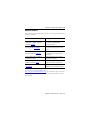
1
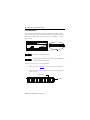
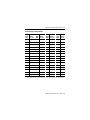
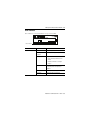
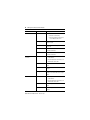
Installation Instructions
XM Dynamic Measurement Module
Catalog Number 1440-DYN02-01RJ
Topic
Page
Important User Information
2
Environment and Enclosure
3
North American Hazardous Location Approval
4
European Hazardous Location Approval
5
Prevent Electrostatic Discharge
6
About the Module
7
Install the Module
8
Set the Node Address
10
Self-Test
12
Status Indicators
13
Specifications
15
Additional Resources
19
2 XM Dynamic Measurement Module
Important User Information
Solid state equipment has operational characteristics differing from those of electromechanical
equipment. Safety Guidelines for the Application, Installation and Maintenance of Solid State Controls
(Publication SGI-1.1 available from your local Rockwell Automation sales office or online at
http://literature.rockwellautomation.com) describes some important differences between solid state
equipment and hard-wired electromechanical devices. Because of this difference, and also because of
the wide variety of uses for solid state equipment, all persons responsible for applying this equipment
must satisfy themselves that each intended application of this equipment is acceptable.
In no event will Rockwell Automation, Inc. be responsible or liable for indirect or consequential damages
resulting from the use or application of this equipment.
The examples and diagrams in this manual are included solely for illustrative purposes. Because of the
many variables and requirements associated with any particular installation, Rockwell Automation, Inc.
cannot assume responsibility or liability for actual use based on the examples and diagrams.
No patent liability is assumed by Rockwell Automation, Inc. with respect to use of information, circuits,
equipment, or software described in this manual.
Reproduction of the contents of this manual, in whole or in part, without written permission of Rockwell
Automation, Inc., is prohibited.
Throughout this manual, when necessary, we use notes to make you aware of safety considerations.
WARNING
IMPORTANT
ATTENTION
SHOCK HAZARD
BURN HAZARD
Identifies information about practices or circumstances that can cause an explosion in
a hazardous environment, which may lead to personal injury or death, property
damage, or economic loss.
Identifies information that is critical for successful application and understanding of
the product.
Identifies information about practices or circumstances that can lead to personal
injury or death, property damage, or economic loss. Attentions help you identify a
hazard, avoid a hazard and recognize the consequences.
Labels may be on or inside the equipment (for example, drive or motor) to alert people
that dangerous voltage may be present.
Labels may be on or inside the equipment (for example, drive or motor) to alert people
that surfaces may reach dangerous temperatures.
Publication ICM-IN002A-EN-P - March 2009
XM Dynamic Measurement Module 3
Environment and Enclosure
ATTENTION
This equipment is intended for use in a Pollution Degree 2 industrial
environment, in overvoltage Category II applications (as defined in IEC
publication 60664-1), at altitudes up to 2000 meters (6562 ft) without derating.
This equipment is considered Group 1, Class A industrial equipment according
to IEC/CISPR Publication 11. Without appropriate precautions, there may be
potential difficulties ensuring electromagnetic compatibility in other
environments due to conducted as well as radiated disturbance.
This equipment is supplied as open-type equipment. It must be mounted within
an enclosure that is suitably designed for those specific environmental
conditions that will be present and appropriately designed to prevent personal
injury resulting from accessibility to live parts. The enclosure must have
suitable flame-retardant properties to prevent or minimize the spread of flame,
complying with a flame spread rating of 5VA, V2, V1, V0 (or equivalent) if
non-metallic. The interior of the enclosure must be accessible only by the use
of a tool. Subsequent sections of this publication may contain additional
information regarding specific enclosure type ratings that are required to
comply with certain product safety certifications.
In addition to this publication, see:
• Industrial Automation Wiring and Grounding Guidelines, for additional
installation requirements, Allen-Bradley publication 1770-4.1.
• NEMA Standards publication 250 and IEC publication 60529, as
applicable, for explanations of the degrees of protection provided by
different types of enclosure.
Publication ICM-IN002A-EN-P - March 2009
4 XM Dynamic Measurement Module
North American Hazardous Location Approval
The following information applies when
operating this equipment in hazardous
locations.
Informations sur l’utilisation de cet
équipement en environnements dangereux.
Products marked "CL I, DIV 2, GP A, B, C, D" are suitable for
use in Class I Division 2 Groups A, B, C, D, Hazardous
Locations and nonhazardous locations only. Each product is
supplied with markings on the rating nameplate indicating
the hazardous location temperature code. When
combining products within a system, the most adverse
temperature code (lowest "T" number) may be used to help
determine the overall temperature code of the system.
Combinations of equipment in your system are subject to
investigation by the local Authority Having Jurisdiction at
the time of installation.
Les produits marqués "CL I, DIV 2, GP A, B, C, D" ne
conviennent qu'à une utilisation en environnements de
Classe I Division 2 Groupes A, B, C, D dangereux et non
dangereux. Chaque produit est livré avec des marquages sur
sa plaque d'identification qui indiquent le code de
température pour les environnements dangereux. Lorsque
plusieurs produits sont combinés dans un système, le code de
température le plus défavorable (code de température le plus
faible) peut être utilisé pour déterminer le code de
température global du système. Les combinaisons
d'équipements dans le système sont sujettes à inspection par
les autorités locales qualifiées au moment de l'installation.
WARNING
EXPLOSION HAZARD • Do not disconnect equipment unless
power has been removed or the
area is known to be nonhazardous.
• Do not disconnect connections to
this equipment unless power has
been removed or the area is known
to be nonhazardous. Secure any
external connections that mate to
this equipment by using screws,
sliding latches, threaded
connectors, or other means
provided with this product.
• Substitution of components may
impair suitability for Class I,
Division 2.
• If this product contains batteries,
they must only be changed in an
area known to be nonhazardous.
Publication ICM-IN002A-EN-P - March 2009
AVERTISSEMENT
RISQUE D’EXPLOSION –
• Couper le courant ou s'assurer
que l'environnement est classé
non dangereux avant de
débrancher l'équipement.
• Couper le courant ou s'assurer
que l'environnement est classé
non dangereux avant de
débrancher les connecteurs. Fixer
tous les connecteurs externes
reliés à cet équipement à l'aide
de vis, loquets coulissants,
connecteurs filetés ou autres
moyens fournis avec ce produit.
• La substitution de composants
peut rendre cet équipement
inadapté à une utilisation en
environnement de Classe I,
Division 2.
• S'assurer que l'environnement est
classé non dangereux avant de
changer les piles.
XM Dynamic Measurement Module 5
European Hazardous Location Approval
European Zone 2 Certification (The following applies when the product bears the
Ex or EEx Marking)
This equipment is intended for use in potentially explosive atmospheres as defined by
European Union Directive 94/9/EC and has been found to comply with the Essential Health
and Safety Requirements relating to the design and construction of Category 3 equipment
intended for use in potentially explosive atmospheres, given in Annex II to this Directive.
Compliance with the Essential Health and Safety Requirements has been assured by
compliance with EN 60079-15 and EN 60079-0.
ATTENTION
This equipment is not resistant to sunlight or other sources of UV radiation.
WARNING
This equipment must be installed in an enclosure providing at least IP54
protection when applied in Zone 2 environments.
WARNING
This equipment shall be used within its specified ratings defined by
Allen-Bradley.
WARNING
WARNING
Provision shall be made to prevent the rated voltage from being exceeded by
transient disturbances of more than 40% when applied in Zone 2
environments.
This equipment must be used only with ATEX certified backplanes.
Publication ICM-IN002A-EN-P - March 2009
6 XM Dynamic Measurement Module
WARNING
WARNING
Secure any external connections that mate to this equipment by using screws,
sliding latches, threaded connectors, or other means provided with this
product.
Do not disconnect equipment unless power has been removed or the area is
known to be nonhazardous.
Prevent Electrostatic Discharge
ATTENTION
ATTENTION
ATTENTION
This equipment is sensitive to electrostatic discharge, which can cause
internal damage and affect normal operation. Follow these guidelines when
you handle this equipment:
• Touch a grounded object to discharge potential static.
• Wear an approved grounding wriststrap.
• Do not touch connectors or pins on component boards.
• Do not touch circuit components inside the equipment.
• Use a static-safe workstation, if available.
• Store the equipment in appropriate static-safe packaging when not in
use.
This product is grounded through the DIN rail to chassis ground. Use zinc
plated yellow-chromate steel DIN rail to assure proper grounding. The use of
other DIN rail materials (for example, aluminum or plastic) that can corrode,
oxidize, or are poor conductors, can result in improper or intermittent
grounding. Secure DIN rail to mounting surface approximately every 200 mm
(7.8 in.) and use end-anchors appropriately.
Do not remove or replace a Terminal Base unit while power is applied.
Interruption of the backplane can result in unintentional operation or machine
motion.
Publication ICM-IN002A-EN-P - March 2009
XM Dynamic Measurement Module 7
About the Module
The 1440-DYN02-01RJ module is a 2-channel general purpose monitor that
supports measurements of dynamic inputs such as vibration, pressure, and
strain.The module can be used for monitoring shaft, casing, and pedestal
vibration in rotating equipment. Inputs accepted include eddy current probe,
standard integrated electronics piezoelectric (IEPE) accelerometer, or voltage
output measurement device such as a pressure transducer. The module also
accepts a tachometer input to provide speed measurement and order analysis
functions. The module can work with most tachometer signal sources such as
eddy current probe, unpowered magnetic probe, and other powered and
unpowered tachometer sensors.
The module provides onboard processing of critical vibration parameters and
advanced alarm and virtual relay logic. It can be integrated with existing
automation and control systems, including PLC’s and displays, to provide
information to aid in protecting machinery from catastrophic failures.
DYNAMIC MEASUR
EMENT
1440-DYN02-01RJ
Publication ICM-IN002A-EN-P - March 2009
8 XM Dynamic Measurement Module
Install the Module
The module mounts on a 1440-TBS-J terminal base unit. We recommend that
you insert the module after you have connected the wiring on the terminal
base unit. Refer to the XM Dynamic Measurement Terminal Base Installation
Instructions, publication ICM-IN003, for wiring information.
ATTENTION
ATTENTION
The 1440-DYN02-01RJ module is compatible only with the 1440-TBS-J
terminal base unit. The keyswitch on the terminal base unit should be at
position 1 for the module.
Do not attempt to install the 1440-DYN02-01RJ module on other
terminal base units.
Do not change the position of the keyswitch after wiring the terminal
base units.
To comply with the CE Low Voltage Directive (LVD), all connected I/O must be
powered from a source compliant with the following: Safety Extra Low Voltage
(SELV) or Protected Extra Low Voltage (PELV).
To comply with UL restrictions, this equipment must be powered from a source
compliant with the following: Class 2.
WARNING
If you insert or remove the module while backplane power is on, an electrical
arc can occur. This could cause an explosion in hazardous location
installations.
Be sure that power is removed or the area is nonhazardous before proceeding.
WARNING
If you connect or disconnect wiring while the field-side power is on, an
electrical arc can occur. This could cause an explosion in hazardous location
installations. Be sure that power is removed or the area is nonhazardous
before proceeding.
Publication ICM-IN002A-EN-P - March 2009
XM Dynamic Measurement Module 9
1. Make certain the keyswitch (D) on the terminal base unit (E) is at
position 1 as required for the module.
C
D
B
E
F
A
G
31886
2. Make certain the side connector (B) is pushed all the way to the left.
You cannot install the module unless the connector is fully
extended.
3. Make certain that the pins on the bottom of the module are straight so
they will align properly with the connectors in the terminal base unit.
4. Position the module (A) with its alignment bar (G) aligned with the
groove (F) on the terminal base.
5. Press firmly and evenly to seat the module in the terminal base unit.
The module is seated when the latching mechanism (C) is locked into
the module.
6. Repeat the above steps to install the next module in its terminal base.
Publication ICM-IN002A-EN-P - March 2009
10 XM Dynamic Measurement Module
Set the Node Address
The module has a DIP switch for setting the network node address. DIP
switches 5 through 10 set the module’s node address using binary addressing.
The module is shipped from the factory with the node address set to 63 (as
shown below).
DYNAMIC MEASUREMENT
TIP
TIP
1440-DYN02-01RJ
DIP switches 1 through 4 are not used.
The node addresses start with 1 for the module closest to the ACNR, and
increase for each consecutive module.
Follow the steps below to set the node address.
1. Refer to the table on page 11 for the switch settings of an address.
2. Using a pointed tool, slide switches 5 through 10 to the appropriate
positions (1 or 0).
Down position = 0
Up position =1
Publication ICM-IN002A-EN-P - March 2009
XM Dynamic Measurement Module 11
Switch Settings for Node Address
Switch
Node Setting
Addr SW5->SW10
Node
Addr
Switch
Setting
SW5->SW10
Node
Addr
Switch
Setting
SW5->SW10
Node
Addr
Switch
Setting
SW5->SW10
0(1)
000000
16
010000
32
100000
48
110000
1
000001
17
010001
33
100001
49
110001
2
000010
18
010010
34
100010
50
110010
3
000011
19
010011
35
100011
51
110011
4
000100
20
010100
36
100100
52
110100
5
000101
21
010101
37
100101
53
110101
6
000110
22
010110
38
100110
54
110110
7
000111
23
010111
39
100111
55
110111
8
001000
24
011000
40
101000
56
111000
9
001001
25
011001
41
101001
57
111001
10
001010
26
011010
42
101010
58
111010
11
001011
27
011011
43
101011
59
111011
12
001100
28
011100
44
101100
60
111100
13
001101
29
011101
45
101101
61
111101
14
001110
30
011110
46
101110
62
111110
15
001111
31
011111
47
101111
63
111111
(1)
Do not set the node address to 0. Node addresses start with 1 for the module closest to the ACNR.
Publication ICM-IN002A-EN-P - March 2009
12 XM Dynamic Measurement Module
Self-Test
The XM module performs a self-test when it powers up. The self-test includes
an LED test and a device test. During the LED test, the indicators will turn
on independently and in sequence for approximately 0.25 seconds.
The device test occurs after the LED test. The Module Status (MS) indicator
is used to indicate the status of the device self-test.
MS Indicator State
Description
Flashing Red and Green
Device self-test is in progress.
Solid Green or Flashing Green
Device self-test completed successfully, and
the firmware is valid and running.
Flashing Red
• Device self-test completed, the hardware
is OK, but the firmware is invalid.
• The firmware download is in progress.
Solid Red
Unrecoverable fault, hardware failure, or Boot
Loader program may be corrupted.
Publication ICM-IN002A-EN-P - March 2009
XM Dynamic Measurement Module 13
Status Indicators
The module has seven LED indicators on top of the module.
DYNAMIC MEASUREMENT
1440-DYN02-01RJ
Status Indicators
Indicator
State
Description
Module Status (MS)
Off
No power applied to the module.
Alternating
Red/Green
Module performing power-up self-test.
Flashing Red
• Application firmware is invalid or not
loaded. Download firmware to the
module.
• Firmware download is currently in
progress.
Solid Red
An unrecoverable fault has occurred. The
module may need to be repaired or
replaced.
Flashing Green
Module operating in Program Mode.
Solid Green
Module operating in Run Mode.
Publication ICM-IN002A-EN-P - March 2009
14 XM Dynamic Measurement Module
Indicator
State
Description
Network Status (NS)
Off
Module is not online.
• Module is autobauding.
• No power applied to the module;
look at Module Status LED.
Channel 0 &
Channel 1
Flashing Red
One or more I/O connections are in the
timed-out state.
Solid Red
Failed communications (duplicate MAC ID
or bus-off).
Flashing Green
Module is online but no connections are
currently established.
Solid Green
Module is online with connections
currently established.
Off
• Normal operation within alarm limits
on the channel.
• No power applied to the module; look
at the Module Status LED.
Tachometer
Solid Yellow
Alarm associated with this channel is in
Alert.
Solid Red
Alarm associated with this channel is in
Danger.
Flashing Red
A transducer fault exists on the channel.
DC bias is outside the DC Low and High
Limits.
Off
• Normal operation within alarm limits
on the channel.
• No power applied to the module; look
at the Module Status LED.
Solid Yellow
Alarm on Speed or Acceleration is in
Alert.
Solid Red
Alarm on Speed or Acceleration is in
Danger.
Publication ICM-IN002A-EN-P - March 2009
XM Dynamic Measurement Module 15
Indicator
State
Description
Flashing Yellow
Tachometer fault other than a transducer
fault (for example no pulse received).
Flashing Red
Tachometer signal DC bias is not within
the DC Low and High Limits.
Setpoint Multiplier
Off
Alarm Limit Multiplier is not in effect.
Solid Yellow
Alarm Limit Multiplier is in effect.
Relay
Off
Virtual relay is not activated.
Solid Red
Virtual relay is activated.
Specifications
XM Dynamic Measurement Module - 1440-DYN02-01RJ
Attribute
Value
Enclosure Type Rating
None (open-style)
Input Voltage (mounted in the 1440-TBS-J)
24V DC
Current Draw Max 250 mA
Output Voltage
-24V DC, 60 mA Max
Isolation Voltage
Not Rated (Class 2 power source required)
No isolation between I/O or backplane
Wire Size
Determined by installed terminal base
Wiring Category
2 - on signal ports
1 - on power ports
2 - on communications ports
North American Temp Code
T4A
IEC Temp Code
T4
(1)
(1)
Use this Conductor Category information for planning conductor routing. Refer to Industrial
Automation Wiring and Grounding Guidelines, publication 1770-4.1.
Publication ICM-IN002A-EN-P - March 2009
16 XM Dynamic Measurement Module
Environmental Specifications
Attribute
Value
Operating Temperature
IEC 60068-2-1 (Test Ad, Operating Cold),
IEC 60068-2-2 (Test Bd, Operating Dry Heat),
IEC 60068-2-14 (Test Nb, Operating Thermal
Shock):
-20…70 °C (-4…158 °F)
Non-Operating Temperature
IEC 60068-2-1 (Test Ab, Unpackaged
Non-operating Cold),
IEC 60068-2-2 (Test Bb, Unpackaged
Non-operating Dry Heat),
IEC 60068-2-14 (Test Na, Unpackaged
Non-operating Thermal Shock):
-40…85 °C (-40…185 °F)
Relative Humidity
IEC 60068-2-30 (Test Db, Unpackaged Damp
Heat):
5…95% non-condensing
Vibration
IEC 60068-2-6 (Test Fc, Operating):
5 g @ 10…500 Hz
Operating Shock
IEC 60068-2-27 (Test Ea, Unpackaged Shock):
15 g
Nonoperating Shock
IEC 60068-2-27 (Test Ea, Unpackaged Shock):
20 g
Emissions
CISPR 11:
Group 1, Class A
ESD Immunity
IEC 61000-4-2:
4 kV contact discharges
Publication ICM-IN002A-EN-P - March 2009
8 kV air discharges
XM Dynamic Measurement Module 17
Environmental Specifications
Attribute
Value
Radiated RF Immunity
IEC 61000-4-3:
10V/m with 1 kHz sine-wave 80% AM
from 80…2000 MHz
10V/m with 200 Hz 50% Pulse 100% AM
at 900 MHz
10V/m with 200 Hz 50% Pulse 100% AM
at 1890 MHz
3V/m with 1 kHz sine-wave 80% AM from
2000…2700 MHz
EFT/B Immunity
IEC 61000-4-4:
±4 kV at 5 kHz on power ports
±2 kV at 5 kHz on signal ports
±2 kV at 5 kHz on communications ports
Surge Transient Immunity
IEC 61000-4-5:
±1 kV line-line (DM) and ±2 kV line-earth
(CM) on power ports
±1 kV line-line (DM) and ±2 kV line-earth
(CM) on signal ports
±2 kV line-earth (CM) on shielded ports
±2 kV line-earth (CM) on communications
ports
Conducted RF Immunity
IEC 61000-4-6:
10V rms with 1 kHz sine-wave 80% AM
from 150 kHz…80 MHz
(1)
Use this Conductor Category information for planning conductor routing. Refer to Industrial
Automation Wiring and Grounding Guidelines, publication 1770-4.1.
Publication ICM-IN002A-EN-P - March 2009
18 XM Dynamic Measurement Module
Certifications
Certifications(1)
(when product is marked)
c-UL-us
Description
UL Listed Industrial Control Equipment, certified for US and
Canada. See UL File E65584.
UL Listed for Class I, Division 2 Group A,B,C,D Hazardous
Locations, certified for U.S. and Canada. See UL File
E194810.
CE
European Union 2004/108/EC EMC Directive, compliant
with:
• EN 61326-1; Meas./Control/Lab., Industrial
Requirements
• EN 61000-6-2; Industrial Immunity
• EN 61000-6-4; Industrial Emissions
• EN 61131-2; Programmable Controllers (Clause 8,
Zone A & B)
C-Tick
Australian Radiocommunications Act, compliant with:
• AS/NZS CISPR 11; Industrial Emissions
Ex
European Union 94/9/EC ATEX Directive, compliant with:
• EN 60079-15; Potentially Explosive Atmospheres,
Protection "n" (II 3 G Ex nA IIC T4 X)
• EN 60079-0; General Requirements (Zone 2)
(1)
See the Product Certification link at http:// www.ab.com for Declarations of Conformity, Certificates,
and other certification details.
Publication ICM-IN002A-EN-P - March 2009
XM Dynamic Measurement Module 19
Additional Resources
These documents contain additional information concerning related Rockwell
Automation products.
Resource
Description
XM Dynamic Measurement Module
Terminal Base Installation Instructions,
publication ICM-IN003
Provides details about how to install the
terminal base for the XM Dynamic
Measurement module.
XM Dynamic Measurement Module User
Manual, publication ICM-UM002
Provides details about how to install, wire
and configure the Dynamic Measurement
module.
XM ControlNet Adapter Installation
Instructions, publication ICM-IN001
Provides details about how to install and
wire the adapter, and adapter technical
specifications.
XM ControlNet Adapter User Manual,
publication ICM-UM001
Provides details about how to install, use
and configure the adapter.
Industrial Automation Wiring and Grounding
Guidelines, publication 1770-4.1
Provides general guidelines for installing a
Rockwell Automation industrial system.
Product Certifications website,
http://ab.com
Provides declarations of conformity,
certificates, and other certification details.
You can view or download publications at
http://literature.rockwellautomation.com. To order paper copies of technical
documentation, contact your local Rockwell Automation distributor or sales
representative.
Publication ICM-IN002A-EN-P - March 2009
Rockwell Automation Support
Rockwell Automation provides technical information on the Web to assist you in using
its products. At http://support.rockwellautomation.com, you can find technical
manuals, a knowledge base of FAQs, technical and application notes, sample code and
links to software service packs, and a MySupport feature that you can customize to
make the best use of these tools.
For an additional level of technical phone support for installation, configuration, and
troubleshooting, we offer TechConnect support programs. For more information,
contact your local distributor or Rockwell Automation representative, or visit
http://support.rockwellautomation.com.
Installation Assistance
If you experience a problem within the first 24 hours of installation, please review the
information that's contained in this manual. You can also contact a special Customer
Support number for initial help in getting your product up and running.
United States
1.440.646.3434
Monday – Friday, 8 a.m. – 5 p.m. EST
Outside United States
Please contact your local Rockwell Automation representative for any
technical support issues.
New Product Satisfaction Return
Rockwell Automation tests all of its products to ensure that they are fully operational
when shipped from the manufacturing facility. However, if your product is not
functioning and needs to be returned, follow these procedures.
United States
Contact your distributor. You must provide a Customer Support case number
(call the phone number above to obtain one) to your distributor in order to
complete the return process.
Outside United States
Please contact your local Rockwell Automation representative for the return
procedure.
Allen-Bradley, Rockwell Automation, and TechConnect are trademarks of Rockwell Automation, Inc.
Trademarks not belonging to Rockwell Automation are property of their respective companies.
Publication ICM-IN002A-EN-P - March 2009
PN 35149
Copyright © 2009 Rockwell Automation, Inc. All rights reserved. Printed in the U.S.A.