1
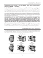
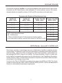
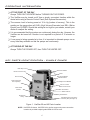
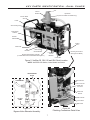
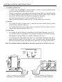
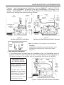
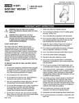
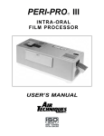
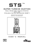
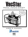
DENTAL VACUUM SYSTEM Part Numbers: VS2O, VS40, VS50, VS50H, VS80 and VS80H WE RECOMMEND DAILY USE OF CLEANSTREAM USER’S MANUAL TABLE OF CONTENTS SECTION PAGE Congratulations . . . . . . . . . . . . . . . . . . . . . . . . . . . . . . . . . . . . . . . . . . . . . . . . . . . . . . . 3 Purpose of this Manual . . . . . . . . . . . . . . . . . . . . . . . . . . . . . . . . . . . . . . . . . . . . . . . . . 3 Warranty . . . . . . . . . . . . . . . . . . . . . . . . . . . . . . . . . . . . . . . . . . . . . . . . . . . . . . . . . . . . .4 On-Line Warranty Registration . . . . . . . . . . . . . . . . . . . . . . . . . . . . . . . . . . . . . . . . . . . 4 Safety Instructions . . . . . . . . . . . . . . . . . . . . . . . . . . . . . . . . . . . . . . . . . . . . . . . . . . . . . 4 Sizing Guide . . . . . . . . . . . . . . . . . . . . . . . . . . . . . . . . . . . . . . . . . . . . . . . . . . . . . . . . . 5 Optional In-Line Filter Kit . . . . . . . . . . . . . . . . . . . . . . . . . . . . . . . . . . . . . . . . . . . . . . . . 5 Operating Information . . . . . . . . . . . . . . . . . . . . . . . . . . . . . . . . . . . . . . . . . . . . . . . . . . 6 Key Parts Identification - Single Pumps . . . . . . . . . . . . . . . . . . . . . . . . . . . . . . . . . . . . 6 Key Parts Identification - Dual Pumps . . . . . . . . . . . . . . . . . . . . . . . . . . . . . . . . . . . . . . 7 Installation Information . . . . . . . . . . . . . . . . . . . . . . . . . . . . . . . . . . . . . . . . . . . . . . . . . . 8 Product Specifications/Dimensions . . . . . . . . . . . . . . . . . . . . . . . . . . . . . . . . . . . . . . . . Site Requirements . . . . . . . . . . . . . . . . . . . . . . . . . . . . . . . . . . . . . . . . . . . . . . . . . . . . . Replacement/Reorder . . . . . . . . . . . . . . . . . . . . . . . . . . . . . . . . . . . . . . . . . . . . . . . . . . Troubleshooting . . . . . . . . . . . . . . . . . . . . . . . . . . . . . . . . . . . . . . . . . . . . . . . . . . . . . . . Accessories/Options . . . . . . . . . . . . . . . . . . . . . . . . . . . . . . . . . . . . . . . . . . . . . . . . . . . Maintenance . . . . . . . . . . . . . . . . . . . . . . . . . . . . . . . . . . . . . . . . . . . . . . . . . . . . . . . . . 11 11 12 13 13 15 LIST OF ILLUSTRATIONS FIGURE 1 2 2A 3 4 5 6 7 8 9 10 11 12 TITLE PAGE VacStar 20, 40 Parts Location . . . . . . . . . . . . . . . . . . . . . . . . . . . . . . . . . . 6 VacStar 50, 50H, 80 and 80H Parts Location . . . . . . . . . . . . . . . . . . . . . . 7 Plumbing Connections Detail View . . . . . . . . . . . . . . . . . . . . . . . . . . . . . . . 7 Bypass Valve Educator Assembly . . . . . . . . . . . . . . . . . . . . . . . . . . . . . . . 7 VacStar 20, 40 without a HydroMiser or Air/Water Separator . . . . . . . . . . 8 VacStar 50, 80 without a HydroMiser or Air/Water Separator . . . . . . . . . . 8 VacStar with Built-In HydroMiser . . . . . . . . . . . . . . . . . . . . . . . . . . . . . . . . 9 VacStar with Wall Mounted Air/Water Separator . . . . . . . . . . . . . . . . . . . . 9 VacStar with Wall-Mounted HydroMise . . . . . . . . . . . . . . . . . . . . . . . . . . . 9 VacStar Electrical Junction Box - Interior View VacStar 20 . . . . . . . . . . . 10 VacStar Electrical Box Connection . . . . . . . . . . . . . . . . . . . . . . . . . . . . . . 10 Vacuum Relief Valve Filter Location . . . . . . . . . . . . . . . . . . . . . . . . . . . . . 14 Intake Solids Collector Location . . . . . . . . . . . . . . . . . . . . . . . . . . . . . . . . 15 13 Water Inlet Strainer Location . . . . . . . . . . . . . . . . . . . . . . . . . . . . . . . . . . 16 2 CONGRATULATIONS Congratulations on the purchase of your new VacStarTM Dental Vacuum System hereafter referred to as VacStarTM in this manual. Your VacStarTM has been engineered to deliver maximum air flow at the ideal vacuum level without creating traumatic suction pressure that could harm patients’ delicate tissue. The VacStarTM is a water ring pump that produces consistent high-volume air flow, even with multiple users on-line. The balanced, corrosion free bronze impeller minimizes noise and a patented vacuum relief valve monitors and maintains constant uniform vacuum pressure. A capacitor-start type motor, with a highly reliable electrical contactor and powerful transformer can be depended on to start every time. The VacStarTM is designed with everything accessible from the front, including the easy to replace solids collector. If your VacStarTM comes with an integral HydroMiser (VS50H or VS80H), water consumption will be reduced by up to 75%. If not, a HydroMiser can be integrated into your VacStarTM at a later date. The HydroMiser separates the liquid and gas discharge from the operatories. The gases are vented out and the liquid and its particulates are directed down the drain. The clean water extracted during this separation process is directed back toward the VacStarTM where it is mixed with fresh water and then directed into the pump chamber to create vacuum. This efficient reuse of water reduces the VacStar's fresh water consumption. Thousands of dentists have depended on the VacStarTM since 1987. Now that your practice has a VacStarTM, or a VacStarTM with the water saving HydroMiser, you too can depend on constant, uniform delivery of vacuum to your operatories and proven trouble-free operation. PURPOSE OF THIS MANUAL This manual provides installation, operation and maintenance instructions for the support of the six available VacStarTM systems listed below. Review and follow the guidelines included in this User Manual to ensure that the system provides the highest level of service. VacStar Models VS20 2 User Capability VS50 4 User Capability VS80 7 User Capability VS40 3 User Capability VS50H (See Note) 4 User Capability VS80H (See Note) 7 User Capability Note: VS50H and VS80H models include an integral HydroMiser that reduces fresh water consumption 3 WARRANTY The VacStarTM is warranted to be free from defects in material and workmanship from the date of installation for a period of twenty-four (24) months. Any item returned to our factory through an Air Techniques Authorized Dealer, will be repaired or replaced at our option at no charge provided that our inspection shall indicate it to have been defective. Dealer labor, shipping and handling charges are not covered by this warranty. This warranty does not apply to damage due to shipping, misuse, careless handling or repairs by other than authorized service personnel. Warranty is void if equipment is installed or serviced by other than dealer service personnel authorized by Air Techniques. Air Techniques, Inc. is not liable for indirect or consequential damages or loss of any nature in connection with this equipment. This warranty is in lieu of all other warranties expressed or implied. No representative or person is authorized to assume for us any liability in connection with the sale of our equipment. ON-LINE WARRANTY REGISTRATION Quickly and easily register your new VacStarTM on-line. Just have your product model and serial numbers available. Then go to the Air Techniques website, www.airtechniques.com, click the register a product link and complete the registration form. This on-line registration ensures a record for the warranty period and helps Air Techniques keep you informed of product updates and other valuable information. SAFETY INSTRUCTIONS Use of the VacStarTM not in conformance with the instructions specified in this manual may result in permanent failure of the unit. To prevent fire or electrical shock, do not expose this WARNING: appliance to rain in or moisture. All user serviceable items are described in the maintenance section. Manufacturing date code on serial number label is in the format Month YYYY. ATTENTION USERS: Alerts users to important Operating and Maintenance instructions. Read carefully to avoid any problems. Warns users that uninsulated voltage within the unit may be of sufficient magnitude to cause electric shock. I ON O OFF MEDICAL ELECTRICAL EQUIPMENT WITH RESPECT TO ELECTRICAL SHOCK, FIRE, MECHANICAL AND OTHER SPECIFIED HAZARDS ONLY IN ACCORDANCE WITH UL-60601-1, CAN/CSA C22.2 NO.601.1 66CA Indicates the ON and OFF position for the Equipment power switch. Indicates the ON and OFF position for the Equipment power switch. Indicates that the equipment complies with the Medical Device Directive 93/42/EEC. EC REP 4 Medical Device Safety Service Schiffgraben 41 30175 Hannover, Germany SIZING GUIDE Choosing the correct size VacStarTM for your practice depends on the number of HVE (High Volume Evacuator) and SE (Saliva Ejector) users anticipated. To assure optimum vacuum, the vacuum demands should not exceed the number of HVE and SE users shown in the chart below: Recommended Number of Simultaneous Users VacStar 20 HVE’s + SE’s VacStar 40 HVE’s + SE’s *VacStar 50 & 50H *VacStar 80 & 80H 2 + 0 3 + 0 4 + 0 7 + 0 1 + 1 2 + 2 3 + 2 6 + 1 0 + 1 + 4 2 + 4 5 + 3 0 + 6 1 + 5 4 + 4 4 HVE’s + SE’s NOTES: HVE = High Volume Evacuator SE = Saliva Ejector * These combinations apply if both pumps are running together. If only one pump is running, use the Sizing Guide for VacStar 20 or 40. HVE’s + SE’s 3 + 6 2 + 8 1 + 10 0 + 13 OPTIONAL IN-LINE FILTER KIT Since larger quantities of particulates may occur initially when a VacStar is replacing another vacuum pump, an optional In-Line Filter is recommended to be installed at the intake connection (see Key Parts). This In-Line Filter is designed to collect larger quantities of particulates from the discharge BEFORE it flows into the VacStar. The larger quantities of debris is mainly due to the VacStar's increased pulling power and the effectiveness of the CleanStream Evacuation System Cleaner's ability to break down proteinaceous deposits and synthetic debris that have accumulated in the existing vacuum lines. Use the In-Line Filter Kit P/N 55078 for single vacuum pump units VS20 and VS40. The kit part number for twin pump units (VS50, VS50H, VS80 and VS80H) is 55079. Refer to the Maintenance Section for recommended maintenance requirements. 5 OPERATING INFORMATION AT THE START OF THE DAY Always TURN ON THE WATER before TURNING ON THE POWER. The VacStar may be turned on/off from a single, convenient location within the dental suite using a Remote Control Panel (See Optional Accessories). The vacuum level is factory preset at 10 In Hg (inches of mercury). This is the reading on the gauge when all HVE’s (High Volume Evacuator) and SE’s (Saliva Ejector) are CLOSED. Should this setting be too high for your needs, contact your dealer to readjust the setting. It is recommended that the system run continuously during the day. However, the VacStar can be turned off if suction is not required for a period of 15 minutes or longer. If one pump is being operated at a time, it is important to alternate pumps on an every other day schedule so that the pumps are used evenly. AT THE END OF THE DAY Always TURN THE POWER OFF, then TURN THE WATER OFF. KEY PARTS IDENTIFICATION - SINGLE PUMPS Motor Drip Cover Vacuum Breaker Electrical Junction Box Motor Vacuum Gauge Main Circuit Breaker ON/OFF Switch Intake Connection From Operatory Low Voltage Circuit Breaker Push To Connect Water Inlet Connector Intake Solids Collector Water Inlet Strainer Water Solenoid Exhaust Drain 24V Remote Wiring Hard Wired Power Connection Via Handy Box (See Page 10) Figure 1. VacStar 20 and 40 Parts Location NOTE: VACSTAR 20 shown. VACSTAR 40 is similar except main power connection is made via provided hospital grade NEMA 6-15P line cord. 6 KEY PARTS IDENTIFICATION - DUAL PUMPS Vent Vacuum Breaker Hydromiser (Used on VS50H and VS80H Only) Vacuum Relief Valve Frame Vacuum Gauge Intake Solids Collector Exhaust Manifold Leveling Feet Base Plate Inlet Manifold Main Power Circuit Breakers Bypass Valve Educator Assembly (Located inside behind Inlet Manifold See Figure 4) Plumbing Connections (See Figure 3A Below) Low Voltage Circuit Breakers Control Box Figure 2. VacStar 50, 50H, 80 and 80H Parts Location NOTE: VACSTAR 50H Shown, Other Models are Similar VACSTAR BASE PLATE TO HYDROMISER Water Solenoid Push To Connect Water Inlet Connector RECYCLE Water Inlet Strainer BYPASS TO LEFT PUMP Water Solenoid TO RIGHT PUMP Check Valve Base Plate Figure 3. Bypass Valve Educator Assembly Figure 2A Plumbing Connections Detail View 7 INSTALLATION INFORMATION Plumbing (water) lines - To assure that the VacStarTM provides optimum vacuum, incoming water pressure must be maintained between 20 and 100 psi. - If heavy combinations of particulates exist in the incoming water, an in-line filter should be installed. (See Accessories/Options for the Remote Control Water Valve.) This will prevent the VacStar's water inlet filter from clogging too frequently. - Incoming water temperature should be between 40° and 75°F. - Water connection location is shown in Fig. 1 and 2a (water inlet connection). Suction - For VacStar 20 and 40, suction hose is connected at suction intake, found on intake solids collector assembly. See Fig. 1. - For VacStar twin pump units, suction hose is connected at suction intake, found on intake solids collector assembly. See Fig. 2. Drain lines - For VacStar 20 and 40 without a HydroMiser or an Air/Water Separator, see Fig. 4. - For VacStars without a HydroMiser or an Air/Water Separator, the effluent should be discharged into an open drain or a closed vented drain. See Fig. 5. - For VacStars with a HydroMiser (see Fig. 6) or an Air/Water Separator (see Fig. 7), gases should be vented out according to code. The waste water (with particulates) from the operatories can be discharged via an open drain or a closed vented drain. Note: For VacStars without a HydroMiser, the drain may be up to 36" above the unit. DRAIN INSTALLATION CLOSED VENTED DRAIN OR OPEN DRAIN PIPE open floor drain open floor drain Figure 4. VacStar 20, 40 without a HydroMiser or Air/Water Separator Figure 5. VacStar 50, 80 without a HydroMiser or Air/Water Separator 8 INSTALLATION INFORMATION Figures 6, 7 and 8 show the typical installations of the dual VacStarTM models 50, 50H, 80 and 80H. Install the VacStarTM by referring to the figure corresponding to the system to be installed. Single VacStarTM models 20 and 40 are installed in the same manner. Make sure that all notes, warnings and requirements are followed. VENT (See Note) POWER CONNECTION VENT (See Note) AIR/WATER SEPARATOR WATER SUPPLY HYDROMISER FLOOR SINK INTAKE FROM MAIN LINE terminate with 1” FNPT fitting FLOOR SINK Figure 7. VacStar with Wall Mounted Air/Water Separator Figure 6. VacStar with Built-In HydroMiser DRAIN INSTALLATION CLOSED VENTED DRAIN OR OPEN DRAIN PIPE 1/2" COPPER TUBE TERMINAL W/ 1/2" FNPT SHUT OFF VALVE POWER CONNECTION 32” Max Height 1/2" COPPER TUBE TERMINAL W/ 1/2" FNPT SHUT OFF VALVE INTAKE FROM MAIN LINE terminate with 1” FNPT fitting WATER SUPPLY Note: For all installations, vent to outside with 2-inch schedule 40 pipe. WARNING: CONDENSATION OF WATER WILL OCCUR IN VENT PIPING. AVOID ACCUMULATION OF WATER IN VENT, SLOPE PIPING TOWARD SEPARATOR. Wall-mounted HydroMiser If the existing drain is higher than the HydroMiser outlet, the HydroMiser must be mounted so that its outlet is above the drain. The HydroMiser can be installed up to 36" above the base of the VacStar with the HydroMiser Wall Mount Kit (#55087). VENT (See Note) IMPORTANT NOTE: ALL INSTALLATIONS POWER CONNECTION HYDROMISER WATER SUPPLY Ambient temperature for all VacStar installations should be 40°- 104°F (5°- 40°C). 32” Max Height 1/2" COPPER TUBE TERMINAL W/ 1/2" FNPT SHUT OFF VALVE The liquid drain from the HydroMiser or an Air/Water Separator must slope downward at least 1/4" for every 10 feet of run toward the drain. (Avoid local low sections, avoid creating traps in the line.) FLOOR SINK INTAKE FROM MAIN LINE terminate with 1” FNPT fitting Figure 8. VacStar with Wall-Mounted HydroMiser 9 INSTALLATION INFORMATION Electric -VacStar 20, 50, 50H, 80, 80H must be wired directly from an electrical box that complies with local electrical codes to the VacStar’s Electrical Connection Box. See Figure. 10. -All VS40 VacStars are wired with a provided hospital grade NEMA 6-15P line cord and requires a hospital-grade 6-15R receptacle. -If the voltage falls below the minimum 105V or 205V or above the maximum 125V or 240V during operation, a Buck/Boost Transformer must be installed. FOR 230 V, JUMPER TABS ARE PLACED IN POSITION SHOWN (FACTORY SET). FOR 115 V, PLACE JUMPER TABS IN POSITION SHOWN. 12 3 45 6 7 12345 67 Figure 9. VacStar Electrical Junction Box - Interior View VacStar 20 (Factory Set for 230 V) ALL INSTALLATIONS MUST CONFORM TO LOCAL CODES GREEN GREEN BLACK BLACK WHITE WHITE BLUE RED Dual Circuit * Pumps Power Leads RIGHT (L1) BLACK (L2) WHITE LEFT (L1) RED (L2) BLUE * For Single Circuit, connect Black and Red wires together (L1) and White and Blue wires together (L2). VacStar 20 Handy Box Connection VacStar 50, 50H, 80, 80H Handy Box Connection Figure 10. VacStar Electrical Box Connection 10 PRODUCT SPECIFICATIONS/DIMENSIONS Spec/Dimension VacStar Models ELECTRICAL VS20 VS40 VS50 VS50H VS80 VS80H *115/230 230 230 230 230 230 205/240 205/240 205/240 205/240 205/240 *16/8 13.4 16 16 26.8 26.8 20 - 100 20 - 100 20 - 100 20 - 100 20 - 100 20 - 100 Flow Rate Per Pump (gal/min) w/HydroMiser 0.12 0.18 N/A 0.12 N/A 0.18 Flow Rate Per Pump (gal/min) w/o HydroMiser 0.50 0.75 0.50 N/A 0.75 N/A 40 - 75 40 - 75 40 - 75 40 - 75 40 - 75 40 - 75 VACUUM LEVEL Preset at Factory (In Hg) 10 10 10 10 10 10 SHIPPING WEIGHT (lbs) 68 85 160 170 200 210 DIMENSIONS Inches (HxWxD) 14 x 11x 11 17 x 11 x 11 22 x 28 x 16 25 x 28 x 16 22 x 28 16 25 x 28 x 16 Voltage Rating Voltage Minimum/Maximum *110/125 205/240 Full Load Amps WATER Inlet Water Pressure (PSI) Water Temperature (°F) * VacStar 20 may be converted from 230 Volts (Factory Set) to 115 Volts at installation site. See Figure 9. SITE REQUIREMENTS Environment Conditions: Operating Conditions IEC 60601-1 Classification Indoor use at altitudes up to 2000m Temperature 5 to 40° C (41 to 104° F). Maximum relative humidity 80% for temperatures up to 31° C, decreasing linearly to 50% relative humidity at 40° C. Supply voltage fluctuation of +/- 10% of nominal voltage. Not suitable for use in the presence of a flammable anesthetics mixture with air or with oxygen or nitrous oxide. Class I Installation Category Ordinary equipment (IPXO). Does not protect against ingress of water. Unit is suitable for continuous operation. 11 SITE REQUIREMENTS Requirement VacStar Models ELECTRICAL VS20 Minimum Circuit Breaker Rating Wire Size AWG (Minimum Gauge) VS40 VS50 VS50H VS80 VS80H 20A 30A 30A 2 ea. 20A or 1 ea. 40A 2 ea. 20A or 1 ea. 40A 12 10 15 2 ea. 12 or 1 ea. #8 2 ea. 12 or 1 ea. #8 16 22 32 32 44 44 2" schedule 40 pipe 40 - 104°F (5 - 40°C) 2" schedule 40 pipe 40 - 104°F (5 - 40°C) 2" schedule 40 pipe 40 - 104°F (5 - 40°C) 2" schedule 40 pipe 40 - 104°F (5 - 40°C) 2" schedule 40 pipe 40 - 104°F (5 - 40°C) 2" schedule 40 pipe 40 - 104°F (5 - 40°C) 1 / 1½ 1¼ / 2 1¼ / 1½ 1¼ / 1½ 1½ / 2 1½ / 2 3/4" FNPT 3/4" FNPT 1" FNPT 1" FNPT 1" FNPT 1" FNPT ½” ID ½” ID ½” ID ½” ID ½” ID ½” ID 1 / 1½ 1¼ / 2 1¼ / 1½ 1¼ / 1½ 1½ / 2 1½ / 2 3/4" FNPT 3/4" FNPT 1" FNPT 1" FNPT 1" FNPT 1" FNPT 3/4 / 1½ 1 / 1½ 1 / 1½ 1 / 1½ 1 / 1½ 1 / 1½ 30A(115V) 20A(230V 10(115V) 12(230V)0 PLUMBING Minimum CFM @ 0" Hg Air Exhaust Ambient Temperature Overhead Plumbing Main Line Minimum/Maximum Inside Diameter (inches) End Fitting Maximum Riser Diameter Overhead Main Line Floor Plumbing Main Line Minimum/Maximum Inside Diameter (inches) End Fitting Maximum Branch Line Diameter Minimum/Maximum Inside Diameter (inches) NOTE: Suction piping must slope at least a ¼” for each 10 feet of run towards the pump. Use PVC Schedule 40 or Copper Type M. ALL INSTALLATIONS MUST CONFORM TO LOCAL CODES REPLACEMENT/REORDER DESCRIPTION MODEL PART NUMBER Solids Collector Replacement Kit VacStar 20, 40 55880 (3/4 inch) VacStar 50, 50H, 80, 80H 55094 (1 inch) All VacStar Models 55094 In-Line Filter Replacement Kit 12 TROUBLESHOOTING PROBLEM POSSIBLE CAUSE POSSIBLE SOLUTIONS 1. Low suction. a. Water filter or solids collector clogged. b. Check valves are stuck. a. Clean/replace filter and/or collector. b. Use a system cleaner like CleanStream; turn vacuum on and off to free check valve. If valve remains stuck, call your authorized Air Techniques dealer for repair service. c. Raise water pressure. d. Open bypass valve to run VacStar. Call your authorized Air Techniques dealer for repair service. e. Call your authorized Air Techniques dealer for repair service. f. Open bypass valve to run VacStar. Call your authorized Air Techniques dealer for repair service. g. Check air exhaust pipe size to make sure it conforms to specification; check for and clear possible restrictions in air exhaust system. c. Low water pressure. d. HydroMiser water recycler is clogged. e. HydroMiser clogged. f. Solenoids not operating. g. Restricted air exhaust. 2 No suction. a. b. c. d. a. b. c. d. f. Solenoids not operating. g. Water off. e. Hose needs to be replaced, call your authorized Air Techniques dealer for repair service. f. Call your authorized Air Techniques dealer for repair service. g. Turn water on via water inlet valve. 3.Excessive suction. a. Relief valve stuck closed. b. Relief valve filter clogged. c. Relief valve set too high. a. Call your authorized Air Techniques dealer for repair service. b. Call your authorized Air Techniques dealer for repair service. c. Lower Relief valve settting. 4 Pumps do not run a. b. a. b. c. a. Turn main circuit breakers on. b. Call your authorized Air Techniques dealer for repair service. a. Call plumber to improve water supply system. b. Call your authorized Air Techniques dealer for repair service. c. Hose needs to be replaced. Call your authorized Air Techniques dealer for repair service. d. Call your authorized Air Techniques dealer for repair service. 5Noisy pumps. Pumps off. Pumps not running. Inlet check valves stuck closed. Water inlet filter and/or solids collector clogged. e. Suction hose collapsed. Main circuit breakers off. Electrical problem. Inadequate water supply. HydroMiser eductor clogged. Drain line collapsed. d. Solenoids not operating. Turn pumps on. Call your authorized Air Techniques dealer for repair service. Call your authorized Air Techniques dealer for repair service. Clean/replace filter. ACCESSORIES/OPTIONS The following lists the description, part number, the applicable model and description for accessory components and options available to maintain and expand the VacStarTM System to meet your professional needs. Contact your Air Techniques Dealer for information. Description Model Part Number HydroMiser Wall Mount Kit Remote Control Panels with 24V switches VacStar 50H, 80H VacStar 20, 40 VacStar 50, 50H, 80, 80H All VacStar Models 55087 53250 or 53251 53113 or 53149 53020 (24V) - 3 4" pipe 53170 (24V) - 1" pipe H-2 H-4 56041 56042 55540 55078 - 3 4" pipe 55079 - 1" pipe 57660 Starter Kit Remote Control Water Valve, with filter HydroMiser Kit Air/Water Separator In-Line Filter Kit CleanStream Evacuation System Cleaner VacStar 20 VacStar 40 VacStar 50 VacStar 80 VacStar 20, 40, 50, 80 VacStar 20, 40 VacStar 50, 50H, 80, 80H All VacStar Models 13 53020-1 (115V) - 3 4" pipe 53171 (115V) - 1" pipe 57640 1 Box of 32 Packets MAINTENANCE Like all precision products, your VacStarTM requires a certain amount of care on a regularly scheduled basis. A well-organized maintenance program aids dependable equipment operation and reduces problems to a minimum. Routine checks help to detect general overall wear, and replacement of parts can often be made before a problem occurs. Consequently, we have established minimum maintenance requirements listed below that include routine inspections and the replacement of filters. Adherence to this recommended maintenance schedule will ensure that the equipment will continue performing at its best with uninterrupted service. Daily Maintenance - Clean vacuum lines Flush all vacuum lines and tubing in the dental system with CleanStream Evacuation System Cleaner. Routine Inspection - Monthly 1. Check tubing for kinks or cracks. 2. Check for abnormal noises and leaks. 3. Dual Units: Make sure both motors are running 4. Check exterior surfaces for dirt and debris, clean if necessary. 5. Make sure that no flammable, corrosive, or combustible materials are stored in the equipment room (especially in the area around the equipment). 6. Refer to Figure 11 and check the vacuum relief valve filter, clean if necessary. Single VacStar Twin VacStar Figure 11. Vacuum Relief Valve Filter Location 14 open floor drain MAINTENANCE Caution: Solids collector may contain biologically hazardous material. Wear protective gloves. Dispose of waste in approved bio-hazard container. Important: When a VacStar is replacing another vacuum pump, clean the collector DAILY during the first week of operation since larger quantities of particulates may initially occur. A worn or missing gasket and/or failure to tightly screw the bowl to the solids collector body will cause poor suction due to air leakage. DO NOT OPERATE THE VACSTAR WITHOUT THE SCREEN INSIDE THE FILTER BOWL. Intake Solids Collector Replacement - Monthly Refer to Figure 12 and using the replacement kit listed below for the specific VacStarTM models, replace the solids bowl, screen and gasket. Do the same replacement if using an optional in-line filter. VacStar Model Solids Collector Kit Part No. Optional In-Line Filter Kit Part No. VS20 & VS40 55880 55094 VS50, VS50H, VS80 & VS80H 55094 55094 Replacement Procedure 1. Turn off the power and water supply. 2. Unscrew the solids bowl (counter clock-wise) and remove the screen and gasket. Dispose of all three items. 3. Assemble a new bowl, screen and gasket included in the Solids Collector Replacement Kit. 4. Install the new solids collector by screwing the bowl into the solids collector body. Figure 12. Intake Solids Collector Location 15 MAINTENANCE Check/Clean Solenoid Water Inlet Strainer - Semi-Annually Check the Inlet Strainer for dirt and debris by performing the following steps. 1. Turn off the power and water supply to the equipment. 2. Use a 1 3/16 inch wrench to unscrew (turn counter clockwise) the cover nut. 3. Remove the cover nut and strainer. 4. Inspect the strainer and clean as necessary. Vacuum Breaker VacStar Models VS20 and VS40 Water Inlet Strainer Nipple Solenoid Electrical Box Front Cover (Secured with 4 screws) Water System Assembly, 55689 Solenoid Retaining Nut VacStar Models VS50, VS50H, VS80 and VS80H Solenoid 1 Water Inlet Strainer Solenoid 2 Electrical Box Front Cover (Secured with 8 screws) Solenoid and Water Inlet Strainer Assembly, 55063 Figure 13. Water Inlet Strainer Location Assembling the Water Inlet Strainer (All Models) 1. Orienting the assembly with the cover nut facing down as shown, seat strainer into the cover nut. 2. Insert the strainer up into the strainer body and tighten the cover nut. 3. Make sure the strainer stays perpendicular to the strainer body. 4. Push up and tighten the cover nut making sure not over tighten. 16 Flow Direction Arrow Strainer Body Mesh Strainer Cover Nut NOTES 17 NOTES 18 NOTES 19 For over 50 years, Air Techniques has been a leading innovator and manufacturer of dental products. Our priority is ensuring complete satisfaction by manufacturing reliable products and providing excellent customer and technical support. Whether the need is digital imaging, utility room equipment or merchandise, Air Techniques can provide the solution via our network of authorized professional dealers. Proudly designed, tested and manufactured in the U.S., our products are helping dental professionals take their practices to the next level. Air Techniques’ family of quality products for the dental professional include: Digital Imaging • • • • • Utility Room • • • • • • Digital Radiography Intraoral Camera Caries Detection Aid Intraoral X-ray Film Processors Dry Vacuums Wet Vacuums Air Compressors Amalgam Separator Utility Accessories Utility Packages Merchandise • • • • • • • • Surface Disinfectant Enzymatic Cleaner Hand Sanitizer and Lotion Waterline Cleaner Evacuation System Cleaner Imaging Accessories Chemistry Processor Accessories Corporate Headquarters 1295 Walt Whitman Road | Melville, New York 11747- 3062 | Phone: 800-247-8324 | Fax: 888-247-8481 Western Facility 291 Bonnie Lane, Suite 101 | Corona, CA 92880 - 2804 | Phone: 800-247-8324 | Fax: 951-898-7646 www. air tec hniques.c om VacStar is a registered trademark of Air Techniques, Inc. © Copyright 2004 Air Techniques, Inc. • P/N 55151CUL Rev. H November 2013