1
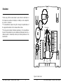
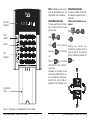
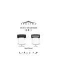
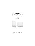
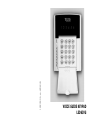
18020502_A_en_LED63VG
VOICE GUIDE KEYPAD
LED63VG
Disclaimer
J2
J1
J0
• While every effort has been made to ensure that the information in
this manual is accurate and complete, no liability can be accepted for
any errors or omissions.
• The manufacturer reserves the right to change the specifications of
the equipment described in this manual without notice.
Wire opening
•
Tamper
This document contains information proprietary to the manufacturer.
No part of this publication may be reproduced, photocopied, stored on a
retrieval system or transmitted, without prior written permission of the
manufacturer.
GREEN
YELLOW
RED
BLACK
GND
JT
INPUT
Figure 2. Back Cover
Voice Guide Keypad - LED63VG User Manual
2
3
23
Voice Guide Keypad - LED63VG User Manual
Real time clock adjustment
key sequence:
CODE
7
CORRECTION
PRG
9
(2 beeps)
ENT
Jumper Settings
Address
0
1
2
3
4
5
6
7
J0
0
0
0
0
1
1
1
1
J1
0
0
1
1
0
0
1
1
J2
0
1
0
1
0
1
0
1
JT
1
0
0
0
0
0
0
0
Contents
Disclaimer
General Information
Limited Warranty
Warnings
Overview
Sound Indication
Voice Messages
LED Indication
Keypad
Operation
Arming
Full
Stay
Force
Instant
Panic
Disarming
Stopping the Alarm
Ambush Code
Voice Guide Keypad - LED63VG User Manual
22
3
2
4
4
4
5
5
5
7
7
8
8
8
8
9
9
10
10
11
11
User Level
Programming
11
User Code Change
Bypassing
Technical Troubles Review
Events Memory Review
Chime Enable/Disable
12
12
12
13
15
Manager Level
Programming
Manager Code Change
Changing User Code/Rights
Events Memory Review
Chime Enable/Disable
Bypassing
Setting the Clock
Setting the Date
Adding a Proximity Card
Removing a Proximity Card
Real Time Clock Adjustment
Jumper Settings
16
16
17
19
19
20
20
20
21
21
21
22
Voice Guide Keypad - LED63VG User Manual
General Information
Limited Warranty
The manufacturer warrants that for
period of 12 months from the date
of purchase, the product shall be
free of defects in material and
workmanship under normal use
and that in fulfillment of any breach
of such warranty, the manufacturer shall, at his discretion, repair
or replace the defective equipment
upon returning it to its factory. This
warranty shall apply to defects in
parts and workmanship only and
not to damages incurred during
shipping or handling, nor due to
causes beyond the control of the
manufacturer such as lightning,
excessive voltage, mechanical
shock, or damages arising from
abuses, unauthorized alternations
or misuse of the equipment.
The warranty shall apply to the
original buyer only, and is and shall
be in lieu of any and all other warranties, whether expressed or implied and of all other obligations or
liabilities on the part of the manufacturer. This warranty contains the
entire warranty. The manufacturer
shall neither assume, nor authorizes any other warranty or liability concerning this product.
In no event shall the manufacturer
be liable for any direct or indirect
or consequential damage, loss of
anticipated profits, loss of time or
any other losses incurred by the
buyer in connection with the purchase, installation or operation or
failure of this product.
The manufacturer recommends
that the entire system be completely tested on a regular basis.
However, despite frequent testing,
and due to, but not limited to,
criminal tampering or electrical disruption, it is possible for this product to fail to perform as expected.
Warnings
Before using the LED63VG Keypad,
please make sure that you have
read and understood the following
instructions. Always make sure that
the LED63VG Keypad is operated
correctly.
Do not attempt to disassemble or
alter any part of the equipment that
is not expressly described in this
guide. Internal inspections, alterations and repairs should be conducted by qualified service personnel only.
Do not use substances containing
alcohol, benzene, thinners or other
flammable substances to clean or
maintain the equipment. The use
Voice Guide Keypad - LED63VG User Manual
4
Adding a Proximity Card
Real Time Clock Adjustment
To use proximity cards the system
has to be equipped with a proximity card reader.
Key sequence for adding a
proximity card:
Arbitrary units are used for real
time clock adjustment. One unit
corresponds to every 5 seconds
deflection per month. The value of
50 means there is no need for adjustment. The following method is
used to calculate the necessary
adjustment.
The necessary adjustment is calculated by determining the number of days taken for the clock to
deflect by 1 minute. The adjustment value is found by dividing the
number 360 by the number of days
found in the previous step. The
result obtained is added to the current value in the case of a slow
clock or is subtracted from the current value in case the clock runs
fast. The figure thus obtained is
entered into the system.
Example: Let us suppose the clock
is running slow by 1 minute in 85
days. The figure 4.2 is obtained
when 360 is divided by 85. The adjustment value of 54 is obtained
when the figure 4 is added to the
current set figure of 50.
CODE
6
PRG
(2
0
USER
ID
(00-16)
beeps)
ENT
The card must be positioned near
the card reader.
Removing a Proximity Card
The key sequence for removing a proximity card:
CODE
6
PRG
(2
1
USER
ID
21
(00-16)
beeps)
ENT
Voice Guide Keypad - LED63VG User Manual
Bypassing
Setting the Clock
To execute a bypass operation the
manager is required to enter his
personal code:
To set the clock the manager is required to enter his personal code.
The set entries are visualized in
binary-hexadecimal form.
Key sequence for setting the
clock:
CODE
PRG
4
0
CODE
Pressing a numeric key bypasses
the respective zone. The display
LED, corresponding to the zone
number, lights up permanently.
Pressing the same key once again
de-bypasses the zone and the LED
goes out.
The selected programming is confirmed by pressing the
ENT
key.
Bypassing sequence (e.g. zone 2):
2
2
(2 beeps)
0
NEW
TIME
(HHMM)
ENT
Setting the Date
To set the date the manager is required to enter his personal code.
The set entries are visualized in
binary-hexadecimal form.
Key sequence for setting the
date:
CODE
2
5
PRG
1
NEW
DATE
5
PRG
(2 beeps)
(DDMM)
ENT
of these substances may lead to
fire.
No liquids should enter the interior.
Overview
The LED63VG Keypad is designed
to control the CA60Plus Control
Panel and provides the user with
system status information.
The Control Panel is fully programmable with the LED63VG keypad.
An LED indication on the keypad
visualizes the system status and
alarm events information.
A sound buzzer informs the user
about correct or incorrect key entries as well as activated alerts.
Seven voice messages provide the
user with addition information.
Sound Indication
There are seven different sound
combinations that indicate seven
different conditions:
• Click – single short beep indicating the pressing of a key;
• Confirm – two long sound signals, indicating the system confirmation to a successfully executed
operation;
• Reject – a single long beep, indicating an incorrectly executed operation;
• Entry time – continuous beep, indicating intrusion into an entrance
zone;
• Exit time – short beeps, indicating the system is armed and the
user is required to leave the entrance zone. Ten seconds before
the exit time is over beep frequency
increases;
• Technical problem – two short
beeps, indicating a technical problem;
• Chime – short beeps with subsequently increasing frequency, indicating intrusion into a zone with an
activated chime option;
Voice Messages
There are seven different voice
messages that indicate different
conditions:
• “System is armed”
• “System is disarmed”
• “Please enter your code to disarm”
• “AC power is lost”
• “Battery is discharged”
• “Please leave the premises”
• “Alarm in the system”
ENT
Voice Guide Keypad - LED63VG User Manual
20
5
Voice Guide Keypad - LED63VG User Manual
NOTE: Forbidding all user permissions will automatically erase the
programmed code combination.
Events Memory Review
Zone LED
Indicators
To review event memory the manager is required to enter a valid
personal code.
Microspeaker
CODE
Keypad
Press
To enable or disable chime mode
the manager is required to enter a
valid code.
Chime enable/disable key sequence:
CODE
MEM
for a following
one.
Press the
ENT
PRG
3
0
to for a previous
event and
LED
Indicators
Chime Enable/Disable
key to see more
Pressing
any
numeric
key
alternatingly switches state of
chime on and off. The preferred
state is confirmed by pressing the
ENT
key.
information on a zone number or
a user code.
Information on the events, as well
as the zone numbers and the users is presented in binary-hexadecimal form. Use the table on
pages 14 and 15 to interpret them.
Keypad Cover
(open)
ENT
Figure 1. Frontal view of the keypad with the cover opened
Voice Guide Keypad - LED63VG User Manual
6
19
Voice Guide Keypad - LED63VG User Manual
Now the manager can switch over
between code change mode and
user permissions mode, using the
and
LED Indication
keys.
Originally the system is in code
change mode. LEDs 3, 4, 5 and 6
light up to indicate the number of
code digits left to be entered.
Bypass
Disarm
Full arm
Stay arm
Review
event memory
Force arm
Pressing
a
numeric
key
alternatingly switches over the
state of the respective operation
from forbidden to permitted.
Selection is confirmed by pressing
The manager is expected to enter
the new user code.
Entering new user code key
sequence:
NEW
CODE
beeps)
(4 digits)
NEW
CODE
the
ENT
key.
User permissions key sequence:
3
LED
Light
Blinking
RDY (green)
System ready
Programming mode
ARM (red)
System armed
Exit time / Programming mode
TRBL (red)
-
Technical problem / Programming
mode
BPS (red)
Bypassed zones
-
TAMP (red)
Tamper memory
Tamper
MEM (red)
Alarm memory
Activated fire detector
1 - 6 (red)
Alarm memory
Activated zone detector
Keypad
ARM
arms the system (See page
8)
DISARM
disarms the system (See
page 10)
BPS
bypasses certain zone(s)
(See pages 12, 20)
TRBL
reviews system troubles
(See page 12)
MEM
reviews event memory
(See page 13)
(2
PRG
CLR
(reenter)
The new code is accepted and the
system automatically enters user
permissions mode.
The LEDs indicate the respective
operations the user is allowed to
execute. The lit numbers indicate
the permitted programs.
3
Voice Guide Keypad - LED63VG User Manual
3
ENT
18
7
ENT
activates programming
mode (See pages 11, 16)
clears entered data or
transfers to previous
menu level
confirms entered data or
transfers to next menu
level
scroll event memory (See
pages 13, 19)
Voice Guide Keypad - LED63VG User Manual
Operation
Stay
Arming
The system can be armed only if
the green RDY1 LED is lit up.
Full
Full arming means all zones are
secured. Anyone coming into the
entrance zone is required to enter
a code. Otherwise the alarm is triggered after entrance time is over.
Full arming sequence:
CODE
ARM
Quick full
quence:
ARM
arming
0
CODE
se-
The new code has been accepted
and the system automatically enters remote access permissions
mode.
The LEDs stand for the remote access allowable operations. The lit
numbers indicate the permitted
programs.
3
3
1
ARM
Remote access permissions
key sequence:
3
Quick stay arming key sequence:
ARM
0
key
Stay arming means the user is allowed to stay in (a) certain zone(s),
but the entrance zone is secured.
Anyone coming into the entrance
zone is required to enter a code.
Otherwise the alarm is set off after the entrance time is over.
Stay arming key sequence:
Remote
disarm
1
Remote arm
The BPS LED lights up permanently
on the display and the LEDs, corresponding to the numbers of the
zones which are not armed, blink
slowly.
The ARM1 LED lights up.
Remote code
access
Remote
bypass
Remote
event memory
review
Remote
programming
Pressing
a
numeric
key
alternatingly switches over the
state of the respective remote operation from forbidden to permitted.
Pressing the
the selection.
ENT
key confirms
ENT
Changing User Code and
Rights
To change the user code, the manager is required to enter his personal code first before the user
code.
User code change key sequence:
CODE
PRG
USER
(01-16)
ID
(2 beeps)
Voice Guide Keypad - LED63VG User Manual
8
17
Voice Guide Keypad - LED63VG User Manual
Manager Level Programming
As a rule of thumb you can enter
user programming mode using the
following procedure:
Step 1: Enter valid user code
Manager Code Change
Force
Instant
The manager is required to enter
his current personal code before
changing it.
Manager code change key sequence:
Force arming means the system is
armed although in (a) certain
zone(s) there may be obstacles or
troubles.
Forced arming key sequence:
CODE
CODE
Instant arming means the user is
allowed to stay in certain zone(s),
but the entrance zone is secured.
The difference with the stay arming is that intrusion into the entrance zone immediately sets on
the alarm.
Instant stay arming key sequence:
PRG
once
Step 3: Enter a parameter number (two digits - see address table)
Step 4: Change parameter value
Step 5: Press
and
CLR
ENT
The manager can switch between
code change mode and remote access permissions mode with the
and
keys.
to confirm
to reject changes.
A blinking RDY1 LED indicates that
the system is in programming
mode.
The system is originally in change
code mode.
LEDs 3, 4, 5 and 6 light up to indicate the number of code digits left
to be entered.
The manager is expected to enter
the new code.
Key sequence for entering new
manager code:
NEW
CODE
beeps)
Voice Guide Keypad - LED63VG User Manual
(4 digits)
NEW
CODE
ARM
2
Quick forced arming key sequence:
(2 beeps)
0
Step 2: Press
0
PRG
CODE
2
ARM
The BPS LED lights up and the LED’s
corresponding to the numbers of
the zones which are not armed,
blink slowly.
ARM
3
Quick instant stay arming key
sequence:
ARM
3
The BPS LED lights up and the LEDs,
corresponding to the numbers of
the zones, which are not armed,
blink slowly.
(2
(reenter)
16
9
Voice Guide Keypad - LED63VG User Manual
NOTE:
With all arming modes, except Instant, after exit time starts running, the “Please leave the premises” voice message will sound
every 5 seconds. The buzzer will
indicate that exit time is running.
Ten seconds before exit time is over,
beep frequency will increase.
After arming, the “System is
armed” message will be repeated
twice.
After each of the procedures described above, except Instant, a
blinking RDY1 LED also indicates
that exit time is running and that
the user is to leave the armed
zones.
In the events of AC loss and low
battery, the “AC power is lost” or
“Battery discharged” messages will
sound correspondingly 3 times every 5 seconds when arming is attempted.
Panic
Pressing and holding
CLR
+
ENT
sends an alarm
signal to the station without triggering the siren.
Disarming
If a person comes into the entrance zone, the voice message
“System is armed. Please enter
your code to disarm.” will sound
every 5 seconds. The buzzer will
indicate that entry time is running.
The user is required to enter a personal code:
CODE
After a valid code has been entered, the message “System disarmed” will be repeated twice.
If no valid code has been entered
during entry time, the “System is
armed” message will sound.
If an alarm has been triggered in
the system, the message “Alarm
in the system. Please enter your
code to disarm” will be repeated
every 5 seconds.
NOTE: Certain users may not be
allowed to disarm the system.
In the events of AC loss and low
battery, the “AC power is lost” or
“Battery discharged” messages will
sound correspondingly 3 times every 5 seconds when disarming is
attempted.
Event Description
Code
1
2
3
4
5
6
Duress code entry
30
1
2
3
4
5
6
User
Telephone line failure
31
1
2
3
4
5
6
0
Telephone line recovery
32
1
2
3
4
5
6
0
Communication error
33
1
2
3
4
5
6
0
Automatic test
34
1
2
3
4
5
6
0
Manual test
35
1
2
3
4
5
6
0
Fuse blown
36
1
2
3
4
5
6
0
Fuse recovery
37
1
2
3
4
5
6
0
System reset
38
1
2
3
4
5
6
0
Power supply failure
39
1
2
3
4
5
6
0
Power supply recovery
40
1
2
3
4
5
6
0
Battery low or missing
41
1
2
3
4
5
6
0
Battery recovery
42
1
2
3
4
5
6
0
Chime Enable/Disable
To enable or disable chime mode
the user is required to enter a valid
code.
Chime enable/disable key sequence:
CODE
10
3
PRG
Pressing
any
numeric
key
alternatingly switches state of
chime on and off.
The preferred state is confirmed by
pressing the
Voice Guide Keypad - LED63VG User Manual
Zone/User
15
ENT
ENT
key.
Voice Guide Keypad - LED63VG User Manual
Event Description
Code
1
2
3
4
5
6
Zone/User
Alarm activated
1
1
2
3
Alarm deactivated
2
1
2
3
4
5
6
Zone number
4
5
6
Fire alarm activated
3
1
2
Zone number
3
4
5
6
Zone number
Fire alarm deactivated
4
1
2
3
4
5
6
Zone number
Panic alarm activated
5
Panic alarm deactivated
6
1
2
3
4
5
6
Zone number
1
2
3
4
5
6
Zone number
Tamper alarm activated
7
1
2
Tamper alarm deactivated
8
1
2
3
4
5
6
Zone number
3
4
5
6
Zone number
Medical alarm activated
9
1
2
3
4
5
6
Zone number
Medical alarm deactivated
10
1
Zone bypassed
11
1
2
3
4
5
6
Zone number
2
3
4
5
6
Zone number
Zone de-bypassed
12
Fire zone bypassed
13
1
2
3
4
5
6
Zone number
1
2
3
4
5
6
Zone number
Fire zone de-bypassed
Panic zone bypassed
14
1
2
3
4
5
6
Zone number
15
1
2
3
4
5
6
Zone number
Panic zone de-bypassed
16
1
2
3
4
5
6
Zone number
Tamper zone bypassed
17
1
2
3
4
5
6
Zone number
Tamper zone de-bypassed
18
1
2
3
4
5
6
Zone number
Medical zone bypassed
19
1
2
3
4
5
6
Zone number
Medical zone de-bypassed
20
1
2
3
4
5
6
Zone number
Disarming
21
1
2
3
4
5
6
User
Remote disarming
22
1
2
3
4
5
6
User
Zone number
Disarming by switch
23
1
2
3
4
5
6
Arming
24
1
2
3
4
5
6
User
Remote arming
25
1
2
3
4
5
6
User
Arming by switch
26
1
2
3
4
5
6
Zone number
Quick arming
27
1
2
3
4
5
6
None
Engineer menu entry
28
1
2
3
4
5
6
17
Engineer menu exit
29
1
2
3
4
5
6
17
Voice Guide Keypad - LED63VG User Manual
14
Stopping the Alarm
The alarm is stopped by entering
a personal code:
CODE
After a valid code has been entered, the message “System disarmed” will be repeated twice.
NOTE: In the events of AC loss and
low battery, the “AC power is lost”
or “Battery discharged” messages
will sound correspondingly 3 times
every 5 seconds.
After a code has been entered, the
“System disarmed” message will be
repeated twice.
User Level Programming
As a rule of thumb you can enter
user programming mode using the
following procedure:
Step 1: Enter a valid user code
Ambush Code
Step 2: Press
Ambush code is a personal code
that disarms the system, but still
sends an alarm signal. Its purpose
to indicate that the user is forced
to disarm the system against his/
her will. The ambush code is calculated from the personal code by
adding 1 to the last digit.
If the last number is 9, it is replaced
by 0 in the ambush code.
Step 3: Enter a parameter number (one digit - see address table)
Step 4: Change parameter value
Example:
Personal code: 4615
code: 4616
Personal code: 4619
code: 4610
11
Step 5: Press
and
CLR
PRG
ENT
once
to confirm
to reject changes.
A blinking RDY1 LED indicates that
the system is in programming
mode.
Ambush
Ambush
Voice Guide Keypad - LED63VG User Manual
User Code Change
The user is required to enter his/
her current personal code before
changing it.
User code change key sequence:
CODE
PRG
NEW
CODE
(4 digits)
beeps)
Bypassing key sequence (zone
2 used in the example):
2
0
2
2
(2
Battery low
or missing
Communication
error
Fuse
blown
NEW
CODE
(reenter)
Bypassing
To execute a bypass operation the
user is required to enter a valid
code:
ENT
BPS
.
Pressing a numeric key bypasses
the respective zone. The LED, corresponding to the zone number,
lights up. Pressing the same key
once again de-bypasses the zone
and the LED goes out.
The selected programming is confirmed by pressing
ENT
.
Technical Troubles Review
To review troubles the user is required to enter a valid personal
code:
CODE
To review event memory the user
is required to enter a valid personal
code.
CODE
MEM
NOTE: Certain users may not be
allowed to review event memory.
TRBL
In the events of AC loss and low
battery, the “AC power is lost” or
“Battery discharged” messages will
sound correspondingly 3 times every 5 seconds.
Each digit on the display indicates
a specific technical problem.
Voice Guide Keypad - LED63VG User Manual
Phone line
error
Events Memory Review
ENT
CODE
Tamper
AC lost
12
Press
to for a previous
event and
for a following
one.
Press the
ENT
Information on the events, as well
as the zone numbers and the users is presented in binary-hexadecimal form. Use the table above
to interpret them.
For convenience the table also includes a graphic representation of
the LEDs as they light up for the
respective event. A black digit on
white background indicates an extinguished LED, and a white digit
on dark background indicates a lit
up LED. Scroll from LED 1 to LED 6
to determine the correspondence
between the event displayed on
the keypad and the text in the table.
The first 17 rows in the table are
used for coding the user number
and the zones.
Example: Suppose that the event
displayed on the keypad is represented by a LED combination of 2,
3, 5 and 6. The table discloses the
first LED 2 data entry. The next
data entries disclose that of the first
LED 3. Next comes the first data
entry of LED 5 and finally comes
the first data entry of LED 6.This is
the data entry with the ordinal number of 27 “Quick arming”.
key to see more
information on a zone number or
a user code.
13
Voice Guide Keypad - LED63VG User Manual