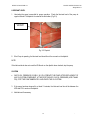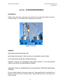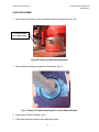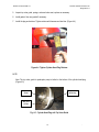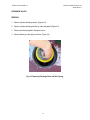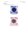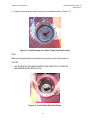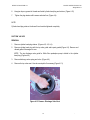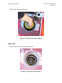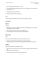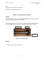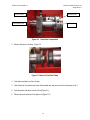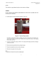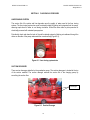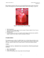
1
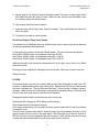
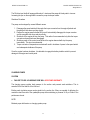
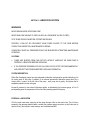
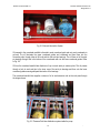
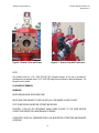
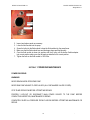
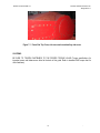
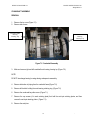
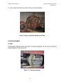
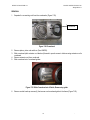
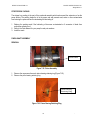
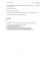
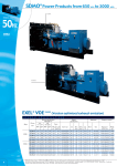
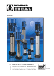
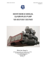
WHITE STAR PUMP CO. MAINTAINENCE MANUAL WSQDM-07-1 MAINTANENCE MANUAL QUADRAPLEX PUMP WS-800/1000/1300/1600 White Star Pump Co. 22718 Commercial Lane, Tomball, Texas 77375 Tel: 281 357 4999 Fax: 281 357 1699 www.whitestarpump.com February 2008 Revision 3 1 WHITE STAR PUMP CO. MAINTAINENCE MANUAL WSQDM-07-1 Contents Page Introduction 3 Section 1 – Installation 5 Section 2 – Lubrication System 11 Section 3 – Inspection and Maintenance 14 Section 4 – Fluid End Maintenance 16 Section 5 – Piston, Piston Rod and Liner 28 Section 6 – Fluid End Accessories 32 Section 7 – Power End Maintenance 36 Appendix 40 2 - WHITE STAR PUMP CO. MAINTAINENCE MANUAL WSQDM-07-1 Introduction: All proper safety precautions and safety regulations must be followed before any work is done on the pump. This section contains the instructions for the installations and startup of the pump at the drilling site. The instructions presented in this section should be followed for the initial Installation and startup of the pump, whenever the pump has been moved to a new location, or whenever the pump has been serviced. Fig 1-1. White Star Quadraplex Pump WARNINGS NEVER REACH INSIDE OPERAING PUMP. NEVER RUN PUMP AGAINST CLOSED VALVES (ALL DISCHARGE VALVES CLOSED). 3 - WHITE STAR PUMP CO. MAINTAINENCE MANUAL WSQDM-07-1 STOP PUMP OPERATION BEFORE ATTEMPTING REPAIRS. PROPERLY LOCK-OUT OR DISCONNECT MAIN POWER SOURCE TO THE PUMP BEFORE CONDUCTING INSPECTION, MAINTENANCE OR REPAIR. COMPLETELY BLEED ALL PRESSURE FROM FLUID END BEFORE ATTEMPTING MAINTENANCE OR REPAIR. CAUTIONS A CHARGING PUMP IS ESSENTIAL FOR PROPER OPERATION. FAILURE TO USE A CHARGING PUMP WILL VOID THE PUMP WARRANTY. INSTALL A SUCTION DESURGER TO MINIMIZE MUD CAVITATION. Fig 1-2 Fluid End 4 - WHITE STAR PUMP CO. MAINTAINENCE MANUAL WSQDM-07-1 SECTION 1. INSTALLATION PUMP 1. Be sure that the pump foundation is level and able to support the weight of the pump. 2. Install the pump as close as possible to the mud tank or pit to reduce pressure drop in suction line. IN LAND INSTALLATIONS: A mat of 3”x12” boards laid side crosswise to the pump skids for the entire length, or at a minimum, is usually sufficient. The boards should be a few feet wider than the width of the pump skid runners. Wet or marshy locations may require a more stable foundation. SUCTION SYSTEM 1. The diameter of the suction line must be equal to or exceed the diameter of the pump suction connection. 2. Use as short a suction line as possible. 3. Install the suction line in as straight a line possible. If turns are necessary use long radius. 4. Install a flexible hose in the suction line to isolate vibration and allow for easier connection. 5. Be sure there are no air traps or air leaks in the suction line. 6. Install a charging pump in the suction line. (See CHARGING PUMPS.) 7. Suction desurgers are installed on White Star Quadraplex to prevent mud cavitations. (Refer to FLUID END ACCESSORIES in Section 4 of this guide.) 8. Fully open all valves in the suction line before operating the pump. DISCHARGE SYSTEM WARNING 5 - WHITE STAR PUMP CO. MAINTAINENCE MANUAL WSQDM-07-1 THE DISCHARGE SYSTEM IS SUBJECT TO HIGH PRESSURES. FAILURE TO FOLLOW APPROVED WELDING PROCEDURES ON ANY OF THE DISCHARGE PIPE MANIFOLDING; OR, PIPING BEYOND MANIFOLD SUBJECTED TO INTERNAL PRESSURES FROM PUMP OPERATION COULD RESULT IN PIPING FAILURE CAUSING EQUIPMENT DAMAGE OR PERSONAL INJURY. 1. Install a pressure relief valve in the discharge system. Be sure there are no valves or restrictions, including the strainer assembly, between the pump and the relief valve. CAUTION THE PRESSURE SETTING OF THE VALVE MUST NOT EXCEED THE PRESSURE RATING OF THE LINER SIZE INSTALLED IN THE PUMP. NOTE: The pressure ratings for the liners are listed in the specification charts at the back of this guide. They are also indicated on the pump serial number plate. 2. Install a pulsation dampener in the discharge system to reduce vibration and increase component service life. (Refer to FLUID END ACCESSORIES in section 4 of this guide.) DIRECTION OF THE PUMP ROTATION 1. Be sure that the pump is set to rotate in the direction indicated by the arrow in the picture below the (Figure 1–3) 2. Do not rotate the pump in the opposite direction of the arrow. 6 - WHITE STAR PUMP CO. MAINTAINENCE MANUAL WSQDM-07-1 Fig. 1-3 Direction of Rotation INITIAL OPERATION Take special care when operating the pump for the first time or after major service have been made. Refer to the caution remarks under STARTUP on Page 1-4. CAUTION PUMPS ARE SHIPPED FROM THE FACTORY WITHOUT LUBRICANT. BE SURE THE PUMP IS FULLY AND PROPERLY LUBRICATED BEFORE OPERATING. STARTUP AND RUN THE OIL LUBE PUMP FOR AT LEAST 30 MIN BEFORE OPERATING THE PUMP. PREPARATION 1. If the pump was not completely assembled at the factory, complete the assembly as required. 2. Check to be sure the suction and discharge systems have been properly installed. (SEE INSTALLATION) 3. Remove the cover plates from the power end. 4. Inspect the power end for contamination. Clean as required. Use magnet to remove any metal particles inside the pump. 5. Drain all condensation from both power end and crosshead compartments using a transfer pump. 7 - WHITE STAR PUMP CO. MAINTAINENCE MANUAL WSQDM-07-1 6. Fill the power end with correct lubricant. 7. Install and seal cover plates after visually checking the lubricant level through the side cover. NOTE: Lubricant specifications and quantities for the pump are listed in LUBRICATION section of this guide and on the pump name plate. 8. Check and lubricate grease fittings on liner rinsing system. 9. Make sure all covers are installed with gaskets and all nuts and bolts are tightened to the torque specifications listed at the back of the guide. 10. Clean out the liner rinse tanks and fill the liner rinsing system with water and / or coolant. NOTE: Add anti-freeze to liner rinsing system if there is a possibility of freezing. CAUTION IF THERE ARE UNUSUAL NOISES OR OTHER INDICATIONS THAT THE PUMP IS NOT OPERATING CORRECTLY, STOP THE PUMP IMMEDIATELY AND CORRECT THE PROBLEM BEFORE CONTINUING OPERATION. IF OIL PRESSURE EXCEEDS 40 PSI OR FALLS BELOW 5 PSI STOP THE PUMP IMMEDIATELY AND CORRECT THE PROBLEM BEFORE CONTINUING. 1. Operate pump slowly at the lowest possible rpm, 65 strokes per minute maximum, for 5 minutes with no fluid end pressure. 2. Be sure that the oil pressure gauge indicates between 5 and 40 psi (Figure 1-5) 8 - WHITE STAR PUMP CO. MAINTAINENCE MANUAL WSQDM-07-1 Fig. 1-5 Oil pressure gauge 3. Check each liner to ensure that the liner rinsing system is operating properly. 4. After 5 minutes of slow speed operation, stop the pump. Allow 10 minutes for oil to return to the crankcase and check the lubricant level. If required, add oil until the level reaches the FULL mark on the dipstick. (Refer to the LUBRICATION section of the guide.) 5. Restart the pump. With no pressure on the fluid end, gradually increase the speed until the normal operating speed is reached. CAUTION IF THERE ARE UNUSUAL NOISES OR OTHER INDICATIONS THAT THE PUMP IS NOT OPERATING CORRECTLY, STOP THE PUMP IMMEDIATELY AND CORRECT THE PROBLEM BEFORE CONTINUING. IF OIL PRESSURE EXCEEDS 40 PSI OR FALLS BELOW 5 PSI STOP THE PUMP IMMEDIATELY AND CORRECT THE PROBLEM BEFORE CONTINUING. 6. Be sure the oil pressure gauge indicates between 5 and 40 psi. 7. Check each liner to ensure that the liner rinsing system is operating properly. 8. Gradually increase fluid end pressure until the desired pressure is reached. WARNING DO NOT EXCEED THE MAXIMUM OPERATING PRESSURE INDICATED ON THE PUMP NAME PLATE AND LISTED IN THE SPECIFIACTION CHARTS IN THIS GUIDE. DO NOT ATTEMPT TO PUMP AGAINST CLOSED DISCHARGE VALVES. 9 - WHITE STAR PUMP CO. MAINTAINENCE MANUAL WSQDM-07-1 9. Operate pump for 30 minutes at required operating pressure. As pump is running inspect around the threaded liners and the valves for leaks. If leaks are found, stop the pump immediately, make the necessary repairs and restart the pump. 10. Stop the pump after 30 minutes of operation. 11. Inspect all studs, nuts and cap screws. Tighten if necessary. Torque specifications are listed at the back of this guide. 12. The pump is now ready for normal operation. Detroit Diesel Engine & Pump Control System. The powertrain for the Quadraplex pump can be either engine driven or electric motor driven depending on customer specifications and requirements. For the engine control system, we use Detroit Diesel engines. This can be of several configurations. Detroit Diesel 12V2000 engine is for quadraplex pumps up to 800 HP. Detroit Diesel 16V2000 engine is for quadraplex pumps 800 to 1300 HP. Detroit Diesel 12V4000 engine is for quadraplex pump 1300 to 1600 HP. Additional information and performance characteristics for each engine can be found in the Detroit diesel users manual. Each engine comes supplied with a Murphylink control panel and a Voith torque converter control box. Startup Procedure. CAUTION: Check around engine and pump prior to startup. Make sure that there is adequate air supply for the TDI air starter or adequate battery power to the electric starter. Make sure that fuel lines are connected and that there is adequate fuel. Check all filters and fluid levels. Check all wiring for damage, replace if necessary. Make sure that the oil lube pump is running and has adequate pressure. Check the water level in the liner rinse pump reservoir and that the flow is adequate. Disengage the battery isolation switch and power up the control panel. Switch engine ON or Engage the TDI Air Starter to start the engine. Allow several minutes for the engine to warm-up. Once engine has warmed up, you can enable the torque converter speed switch to start the procedure to engage the pump. Once the torque converter speed switch is enabled a green light will immediately illuminate to let the operator know that there is power in the speed switch. When the engine rpm is above a minimum of 850 rpm the torque converter engagement light will illuminate to let the operator know that the torque converter has been activated and that very shortly the pump will start to turnover. 10 - WHITE STAR PUMP CO. MAINTAINENCE MANUAL WSQDM-07-1 The RA drive input shaft will engage within about 1 minute and the pump will slowly start to turnover. Increasing the rpm on the engine will increase the pump stroke per minute. Shutdown Procedure The pump can be stopped by several different means. 1. Disengage the speed switch will decouple the torque converter from the engine flywheel and the pump will slow down and stop shortly. 2. Reduce the engine speed to below 850 rpm will automatically disengage the torque converter and the pump will slow down and stop shortly. 3. Shutdown of the engine will stop the pump. This method is recommended only after the torque converter and pump has been disengaged. 4. Shutdown power to the control panel will shut the engine down and will stop the pump immediately. This is not recommended. 5. Torque converter oil temperature overheats will result in shutdown of power to the speed switch and subsequent shutdown of the pump. Once the engine has been shutdown, it is advisable to engage the battery isolation switch to prevent damage to the engine and control panel. CHARGING PUMPS CAUTION FAILURE TO USE A CHARGING PUMP WILL VOID PUMP WARRANTY. The charging pump provides back pressure to the suction and prevents mud cavitations. This is essential to the flow and life of the fluid end. Existing mud circulation pumps can be piped into the suction line if they are capable of delivering the maximum rated flow rate of the quadraplex pump while maintaining a pressure of 40 psi. Refer to the performance charts. NOTE: Maintain proper belt tension on charging system pump. 11 - SECTION 2. LUBRICATION SYSTEM WARNINGS NEVER REACH INSIDE OPERATING PUMP. NEVER RUN PUMP AGAINST CLOSED VALVES (ALL DISCHARGE VALVES CLOSED). STOP PUMP OPERATION BEFORE ATTEMPTING REPAIRS. PROPERLY LOCK-OUT OR DISCONNECT MAIN POWER SOURCE TO THE PUMP BEFORE CONDUCTING INSPECTION, MAINTENANCE OR REPAIR. COMPLETELY BLEED ALL PRESSURE FROM FLUID END BEFORE ATTEMPTING MAINTENANCE OR REPAIR. CAUTIONS PUMPS ARE SHIPPED FROM THE FACTORY WITHOUT LUBRICANT. BE SURE PUMP IS PROPERLY LUBRICATED BEFORE OPERATING. IF OIL PRESSURE EXCEEDS 40 PSI OR FALLS BELOW 5 PSI STOP THE PUMP IMMEDIATELY AND CORRECT THE PROBLEM BEFORE CONTINUING OPERATION. SYSTEM DESCRIPTION White Star Quadraplex pumps have two independent lubrication systems which provide lubricating oil to all moving parts of the pump. In addition to an external pressure-fed lubrication pump driven by a electric motor located at the left side of the pump , each pump has a gravity –fed system that is supplied by splash from the main gear. Normal oil pressure for the external lubrication system, as indicated by the pressure gauge, is 5 to 40 psi depending upon the temperature of the oil and the operating speed of the pump. EXTERNAL LUBE SYSTEM Oil in the crank case sump enters the oil lube pump through a filter on the suction line. The oil is then pumped to the gearcase manifold which contains the pressure gauge connection, a relief valve (set to open at 40 psi), and outlets to main bearings, and crosshead manifold. WHITE STAR PUMP CO. MAINTAINENCE MANUAL WSQDM-07-1 Fig. 2-1 External Lubrication System Oil pumped to the crosshead manifold is directed to each crosshead guide and onto each crosshead via grooves. The oil lubricates the upper crosshead guides and crosshead and then flows into the connecting rods, through holes in the rods and into the wrist pin bearings. The oil flows out of the wrist pin bearings through hole in the bottom of the crossheads and onto the lower crosshead guides. Refer to Fig. 2-2. Oil from the crosshead manifold also feeds an oil cup on each wrist pin retainer plate. This oil passes through a hole in each wrist pin to the inner race of the wrist pin bearings and then onto the lower crosshead guides ensuring adequate lubrication of the bearings. The crosshead manifold also supplies a stream of oil to each extension rod as the rods pass through the stripper boxes. Fig. 2-2 Pressure-Fed Lube distribution system inside the pump 10 - WHITE STAR PUMP CO. MAINTAINENCE MANUAL WSQDM-07-1 OIL SPLASH SYSTEM Each part lubricated by the external lube system also receives oil from the gravity-fed splash lubrication system. The oil in the crank case is brought up by the bull gear and thrown over the crank case to the crosshead bays. The oil splash is then channeled evenly to all 4 crosshead bays by the guide blades built onto the pump top cover (Figure 2-2). Fig. 2-2 Oil Splash when Pump Operates 11 - WHITE STAR PUMP CO. MAINTAINENCE MANUAL WSQDM-07-1 LUBRICANT LEVEL 1. Lubricating the pump is essential for proper operation. Check the lubricant level of the pump at regular intervals. The dipstick is located at the both sides (Fig 2-3). OIL LEVEL DIPSTICK Fig. 2-3. Dipstick 2. If the Pump is operating, the lubricant level should be at the run mark on the dipstick. NOTE: If the lubricant level does not reach the RUN mark on the dipstick when checked, stop the pump. CAUTION WATCH OIL PRESSURE CLOSELY AS YOU OPERATE THE PUMP AFTER REPLACMENT OF ANY OIL SYSTEM COMPONENT. AT THE FIRST SIGN OF LOW OIL PRESSURE (LESS THAN 5 PSI), STOP THE PUMP IMMEDIATELY AND CHECK THE OIL SYSTEM. 3. If the pump has been stopped for at least 10 minutes, the lubricant level should be between the ADD and FULL marks on the dipstick. 4. Add lubricant if necessary. 12 - WHITE STAR PUMP CO. MAINTAINENCE MANUAL WSQDM-07-1 RECOMMENDED LUBRICANTS NOTE: Regular oil changes will extend the life of the pump. The recommended lubricants for the White Star mud pumps are shown in Fig. 2-6. Consult your White Star service representative before using lubricants other than those listed LUBRICANT CHANGES 1. Drain the old lubricant every 4 months or 1000 operating hours, whichever occurs first. Use a transfer pump to drain the oil in the crank case and the crosshead bays. 2. Fill the pump with fresh lubricant specified in Fig. 2-6. CAUTION CHANGE LUBRICANT IF CONTAMINATED BY DIRT, CONDENSATION OR OTHER FOREIGN SUBSTANCES. DRILLING FLUID, EXCESSIVE AMBIENT TEMPERATURE BRAND OF LUBRICANT - 20 Deg F to +15 Deg F +15 Deg. F to 125 Deg F AGMA NO. No. 1 EP No. 4 EP GULF - EP Lubricant 75 EXXON Pen-O-Led EP 1 Pen-O-Led SHELL - Omala EP 150 MOBIL Comp AA Mobilgear 626 Comp. BB Mobilgear 629 TEXXACO Meropa Lubricant 1 Multigear Lubricant EP 80 Meropa Lubricant 2 NOTE: The Capacity of Oil for White Star WS-800-1600 is 120 gal. Fig. 2-6. Recommended lubricants 13 - WHITE STAR PUMP CO. SECTION 3. MAINTAINENCE MANUAL WSQDM-07-1 INSPECTION AND MAINTENANCE WARNINGS NEVER REACH INSIDE OPERATING PUMP. NEVER RUN THE PUMP AGAINST CLOSED VALVES (ALLL DISCHARGE VALVES CLOSED). STOP PUMP OPERATION BEFORE ATTEMPTING REPAIRS. PROPERLY LOCK-OUT OR DISCONNECT MAIN POWER SOURCE TO THE PUMP BEFORE CONDUCTING INSPECTION, MAINTENANCE OR REPAIR. COMPLETELY BLEED ALL PRESSURE FROM FLUID END BEFORE ATTEMPTING MAINTENANCE OR REPAIR. PREVENTIVE MAINTENANCE The primary goal of a preventive maintenance program is to help the pump owner realize and control fluid circulating equipment operating costs. It is possible to control mud pump cost if life of fluid end parts can be reasonably predicted so that they can be replaced before they fail. Parts that are run to the point of failure result in unscheduled downtime, damage to other parts and excessive man hours being spent for pump repair. Besides following a program of scheduled inspection and maintenance, the owner should develop a plan for the timely replacement of expendable components based upon the average life expectancy of these components. By changing expendable parts in a group on a timely basis you can eliminate the need to continually go into the pump for routine maintenance. Changing parts or performing other schedule inspections while you are shut down for some other event that does not require pump operation (making cement, logging, etc.) further reduces pump down time. SCHEDULE MAINTENANCE DAILY (8 HOURS) 1. 2. 3. 4. CHECK CRANKCASE OIL LEVEL. CHECK OIL PRESSURE. CHECK OIL FOR CONTAMINATION. CHECK STRIPPER BOX PACKING. 14 - WHITE STAR PUMP CO. 5. 6. 7. 8. 9. 10. 11. 12. 13. 14. 15. MAINTAINENCE MANUAL WSQDM-07-1 CHECK & LUBRICATE CHARGING PUMP. CHECK ALL BELTS FOR PROPER TIGHTNESS. CHECK DISCHARGE PRESSURE. CHECK FOR OIL LEAKS. CHECK FOR FLUID LEAKS. CHECK SUCTION DESURGER FOR PROPER PRESSURE. CHECK DISCHARGE PULSATION DAMPENER FOR PROPER PRESSURE. CHECK PISTON LUBRICATION SYSTEM. CHECK PUMP FOR CLEANLINESS. CHECK LINER RINSE SYSTEM AND CLEAN/REFILL LEVEL AS NECCESARY. CHECK WORK AREA FOR CLEANLINESS. WEEKLY (40 HOURS). 1. CHECK ALL SAFETY CONTROLS. 2. CHECK PISTON ROD CLAMPS. 3. PERFORM ALL DAILY CHECKS. MONTHLY (200 HOURS). 1. 2. 3. 4. 5. 6. 7. 8. 9. CHECK ALLL FLUID END AND POWER END BOLTS FOR PROPER TIGHTNESS. CHECK LINER AND PISTON FOR WEAR. CHECK EXTENSION ROD FOR WEAR. CHANGE LINER RINSING SYSTEM WATER. CLEAN CRANKCASE BREATHERS. CLEAN OR REPLACE OIL FILTER (S). CHECK VALVE SEATS AND VALVE SPRINGS. CHECK AVAILABILITY AND CONDITION OF SPECIAL TOOLS. PERFORM ALL DAILY AND WEEKLY CHECKS. SIX MONTHS (1000 HOURS) 1. 2. 3. 4. 5. 6. 7. 8. CHECK CROSSHEAD CLEARANCE (SEE SPECIFICATIONS). CHECK FOUNDATIONS AND/ OR HOLD ON BOLTS. CHECK GEARS AND / OR CHAIN AND SPROCKETS FOR WEAR. CHECK SUCTION FLANGE BOLTING. CHECK DISCHARGE FLANGE BOLTING. CHECK PUMP SHEAVE, SPROCKET OR COUPLING. CHANGE OIL. PERFORM DAILY, WEEKLY AND MONTHLY CHECKS. 15 - WHITE STAR PUMP CO. SECTION 4 . MAINTAINENCE MANUAL WSQDM-07-1 FLUID END MAINTENANCE EXPENDABLES Gaskets, valves, valve seats, valve springs, liners and pistons are considered expendable components. A liner davit (Figure. 4-1) is available to aid in handling heavy components. Figure 4-1 Liner davit WARNINGS NEVER REACH INSIDE OPERATING PUMP. NEVER RUN PUMP AGAINST CLOSED VALVES (ALLL DISCHARGE VALVES CLOSED). STOP PUMP OPERATION BEFORE ATTEMPTING REPAIRS. PROPERLY LOCK-OUT OR DISCONNECT MAIN POWER SOURCE TO THE PUMP BEFORE CONDUCTING INSPECTION, MAINTENANCE OR REPAIR. COMPLETELY BLEED ALL PRESSURE FROM FLUID END BEFORE ATTEMPTING MAINTENANCE OR REPAIR. Be sure to tighten fasteners to the proper torque value. Torque specifications for important fluid end fasteners are given at the back of this guide. Refer to standard SAE torque chart for any fasteners not listed in this guide. 16 - WHITE STAR PUMP CO. MAINTAINENCE MANUAL WSQDM-07-1 GASKET REPLACEMENT 1. Use a hammer and steel bar to remove threaded cylinder head plug retainer (Fig. 4-2). CYLINDER HEAD PLUG RETAINER Figure 4-2 Removing cylinder head plug retainer 2. Remove cylinder head plug and gasket from fluid module. (Fig 4-3) Fig. 4-3 Removal of Cylinder Head Plug with Top Valve Guide and Gasket 3. Inspect gasket. Discard if damage or worn. 4. Clean gasket surface and lubricate with multipurpose grease. 17 - WHITE STAR PUMP CO. MAINTAINENCE MANUAL WSQDM-07-1 5. Inspect top valve guide, springs, valve and valve seat, replace as necessary. 6. Install gasket. Use new gasket if necessary. 7. Install the plug and retainer. Tighten retainer with hammer and steel bar. (Figure 4-4) Figure 4-4 Tighten Cylinder Head Plug Retainer NOTE: Note: The top valve guide for quadraplex pump is bolted on the bottom of the cylinder head plug. (Figure 4-5) Top Valve Guide Cylinder Head Plug Plug Seal Gasket Fig. 4-5 Cylinder Head Plug with Top Valve Guide 18 - WHITE STAR PUMP CO. MAINTAINENCE MANUAL WSQDM-07-1 DISCHARGE VALVES REMOVAL 1. Remove cylinder head plug retainer (Figures 4-2). 2. Remove cylinder head plug with the top valve and gasket (Figure 4-3). 3. Remove and discard gasket if damaged or worn. 4. Remove discharge valve spring and valve (Figure 4-6) Fig. 4-6 Removing Discharge Valve and Valve Spring 19 - WHITE STAR PUMP CO. MAINTAINENCE MANUAL WSQDM-07-1 INSTALLATION 1. Position valve on valve seat. (Figures4-7, 4-8) Fig. 4-7 Discharge Valve Seat Fig. 4-8 Position Valve on to Valve Seat 20 - WHITE STAR PUMP CO. MAINTAINENCE MANUAL WSQDM-07-1 2. Place valve spring over valve. (Figure 4-9) Fig. 4-9 Place Valve Spring over Valve 3. Insert valve guide until the center of the guide is over the valve stem and spring (Figure 4-10) Figure 4-10 Insert Discharge Valve Guide/ Cylinder Head Plug 4. Push the valve guide together with the cylinder head plug down over the valve stem and spring. 21 - WHITE STAR PUMP CO. MAINTAINENCE MANUAL WSQDM-07-1 5. Inspect the valve guide and retainer to be sure they are installed correctly. (Figure. 4-11) Figure 4-11 Install Discharge Valve Guide/ Cylinder Head Plug Correctly NOTE: Make sure valve guide retainer is screwed all the way pressing on the cylinder head plug. CAUTION VALVE GUIDE WILL BE DAMAGED DURING PUMP OPERATION IF COCKED OR MISALINGNED DURING INSTALLATION. Figure 4-12 Install Cylinder Head Plug Retainer 22 - WHITE STAR PUMP CO. MAINTAINENCE MANUAL WSQDM-07-1 6. Use pipe dope or grease for threads and install cylinder head plug and retainer. (Figure 4-12) 7. Tighten the plug retainer with hammer and steel bar. (Figure 4-4) NOTE: Cylinder head plug retainer is buttress fit and must be tightened completely. SUCTION VALVES REMOVAL 1. Remove cylinder head plug retainer (Figures 4-2, 4-3, 4-4). 2. Remove cylinder head plug with the top valve guide and inspect gasket (Figure 4-5). Remove and discard gasket if damaged or worn. NOTE: The top discharge valve guide for White Star quadraplex pump is bolted to the cylinder head plug. (Figures 4-5) 3. Remove discharge valve spring and valve (Figure 4-6) 4. Remove the top valve seat. Use valve seat puller if necessary (Figure 4-13) Figure 4-13 Remove Discharge Valve Seat 23 - WHITE STAR PUMP CO. MAINTAINENCE MANUAL WSQDM-07-1 5. Loosen the ½” socket head bolt which holds the lower valve guide retainer. (Figure. 4-14). Figure 4-14 Loosen the Lower Valve Guide Holding Screw 6. Rotate valve guide 90 degrees and loose it from the holding wedge on the module, then remove it by tilting slightly (Figures 4-16). Figure 4-16 Rotate the low valve guide and Remove 24 - WHITE STAR PUMP CO. MAINTAINENCE MANUAL WSQDM-07-1 7. Remove suction valve and valve spring. Figure 4-17 Remove Lower Valve and Spring INSTALLATION 1. Position suction valve on the valve seat. (Figure 4-18) Figure 4-18 Place Valve on the valve seat 25 - WHITE STAR PUMP CO. MAINTAINENCE MANUAL WSQDM-07-1 2. Place suction valve spring over valve. (Figure 4-19) Figure 4-19 Install Valve Spring on Valve 3. Insert the lower valve guide and retainer into the spring over the valve stem correctly. (Figure 4-20). Figure 4-20 Install Lower Valve Guide 4. Place the valve guide retainer into the module correctly by inserting into the module, rotate by 90 degrees with the one side of the retainer lip under the module step and the valve guide above the module step. The opposite side of the retainer should have the retainer lip above the module step with the valve guide below the module step. 5. Tighten the valve guide retainer bolt down onto the valve guide to lock the valve guide into position. (Figure 4-14). 6. Position top valve on valve seat (Figure 4-13). 26 - WHITE STAR PUMP CO. MAINTAINENCE MANUAL WSQDM-07-1 7. Place valve spring over valve (Figures 4-7, 4-8, 4-9). 8. Insert valve guide with the cylinder head plug until the center of the guide is over the valve stem and spring (Figure 4-10, 4-11) 9. Install threaded plug retainer. (Figure 4-12). 10. Tighten with hammer and steel bar. (Figure 4-4). NOTE: Threaded cylinder head plug retainer is buttress fit and must be tightened completely. VALVE SEATS REMOVAL CAUTION NEVER USE A TORCH TO REMOVE VALVE SEATS. EXCESSIVE HEAT WILL DISTORT FORGINGS AROUND VALVES SEATS. 1. Remove valve guide and valve (see section on appropriate valve). 2. Use a suitable puller to remove valve seat. (See CAUTION and NOTE). INSTALLATION NOTE: Do not re-use valve seats. Always replace removed valve seats with a new one. 1. Remove all mud and scale from area that valve seat contacts with wire brush. 2. Thoroughly clean the area that the valve seat contacts with rags and a suitable cleaning solution. WARNING NEVER USE GASOLINE AS A CLEANING SOLUTION. 3. Wipe the contact area dry with a soft clean rag. Area must be completely dry before installing valve seat. 4. Install valve seat into the tapered area. 5. Drive the valve seat into place with a hammer and wooden block. 27 - WHITE STAR PUMP CO. MAINTAINENCE MANUAL WSQDM-07-1 NOTE: Pump pressure will drive the seat into its final position. 6. Install the valve, valve spring and valve guide. SECTION 5 PISTON AND PISTON ROD AND LINER WARNING USE THE LINER DAVIT (Figure 4-1) WHEN HANDLING LINERS AND PISTONS. LINERS AND PISTONS ARE HEAVY AND WORK SPACE IS CONFINED. White Star Quadraplex pumps have API SA-4 piston rod connections designed for single acting pistons and 1-1/2 inch diameter bores in the piston body. The threads on the piston rods are 1-1/2”-8UN. PISTON ROD PISTON STOP NUT Figure 5-1 Piston and Piston Rod REMOVAL 1. Completely retract the extension rod. (Figure 5-2). 28 - WHITE STAR PUMP CO. MAINTAINENCE MANUAL WSQDM-07-1 Extension Rod Threaded Liner Piston Rod Clamp Piston Rod Figure 5-2 Piston Rod Compartment 2. Remove the piston rod clamp. Figure 5-3. Figure 5-3 Remove Piston Rod Clamp 3. Push piston and piston rod into the liner. 4. Unlock the liner lock system and loosen the threaded liner and remove the liner with piston rod in it. 5. Push the piston and piston rod out of liner (Figure 5-1). 6. Remove stop nut and piston from piston rod (Figure 5-1). 29 - WHITE STAR PUMP CO. MAINTAINENCE MANUAL WSQDM-07-1 INSTALLATION NOTE : Burrs and rough spots on the extension and piston rod flanges will cause piston and liner misalignment. Before re-assembly and installation, inspect the extension and piston rod flanges. Remove any burrs or rough spots by filling or grinding. 1. Install new piston with O-ring and piston guide onto piston rod. 2. Install stop nut on piston rod. Torque stop nut to 870 ft-lbs. 3. Lubricate liner bore and piston with multipurpose grease. 4. Insert the assembled piston and piston rod into the liner. 5. Inspect the liner radial seals on the module, Discard if damage or worn. 6. Inspect the liner face seal, Discard if damage or worn. Lubricate the liner face and the seal groove or recess and install a liner face seal onto the front of the liner. 7. Grease the liner boss and face with heavy grease. This lubrication prevents corrosion and aids in removal of the liner for later maintenance or replacement. 8. Clean the liner bore and face of the fluid end. 8. Install the liner in the fluid module liner bore. Screw the liner into the bore until it stops against fluid end block but be sure NOT TO TIGHTEN THE LINER. 9. Position the piston rod flange against the extension rod flange with the pilot boss on the piston rod fitting into the hole in the extension rod. (Figure 5-4). PISTON ROD BOSS Figure 5-4 Piston Align to Extension Rod 30 - WHITE STAR PUMP CO. MAINTAINENCE MANUAL WSQDM-07-1 NOTES: There should be no gaps between the piston rod and extension rod flanges. WARNING DO NOT TIGHTEN THE THREADED LINER BEFORE THE PISTON ROD IS ALIGNED WITH THE EXTENSION ROD PROPERLY. 10. Install the piston rod clamp and tighten completely. (Figure 5-4). Figure 5-4 Piston Rod Clamp Installed If the piston rod clamp will not tighten completely, inspect the clamping faces of the extension rod, piston rod and clamp for grooves or burrs. Carefully remove any grooves or burrs on the clamping faces by filing or grinding. 11. Torque the ¾”clamp bolts evenly to 200 ft-lb. The clamp should fit tightly around the rod flanges and should not rotate. 12. Move the piston deep inside the liner by rotating the pump. 13. Tighten the threaded liner with a steel bar and hammer. 14. Move liner lock system into the lock position. Note: Threaded liner is buttress fit and must be completely tight. 31 - WHITE STAR PUMP CO. MAINTAINENCE MANUAL WSQDM-07-1 SECTION 6 FLUID END ACCESSORIES LINER RINSING SYSTEM The service life of the piston and liner depends upon the quality of water used in the liner rinsing system. The liner rinsing system has a self contained potable 90 gallon tank integrated into the pump, assuring ample time for water to cool during circulation. White Star offers either a pinion-powered or electrically-powered self contained pump system. Periodically check and clean the tank of the self contained system by flushing out sediment through the drains on the side of the pump underneath the crosshead bay (Figure 5-5). Figure 6-1 Liner rinsing system drain SUCTION DESURGER There are two desurgers installed on the quadraplex pump. The suction desurgers is located at the top of the suction manifold. The suction desurger extends the service life of the charging pump by smoothing the suction flow. Desurger Figure 6-2 Suction Desurger 32 - WHITE STAR PUMP CO. MAINTAINENCE MANUAL WSQDM-07-1 Before starting the pump for the first time, as well as periodically during pump operation, check the air pressure in the desurgers from the pressure gauges installed on the top of each desurger. (Figure 6-3) Figure 6-3 Suction Desurger & Pressure Gauge 1. Open the angle valve. 2. Use a standard tire pressure gauge to check air pressure. Pressure should be 20 psi. If low use standard air compressor to fill to 20 psi. 3. Close angle valve. 4. If pressure integrity is lost at any time, inspect the rubber diaphragm inside the suction manifold for damage. Tighten the hose clamps or replace the diaphragm if necessary. STRAINER ASSEMBLY This standard accessory consists of a studded strainer body, a bull plug flange and strainer screen (Figure 6-4). The strainer assembly strains the mud to prevent trash from entering the high pressure mud system. Inspect the strainer screen at regular intervals or if relief valve discharges excessively. WARNING COMPLETELY BLEED ALL PRESSURE FROM FLUID END BEFORE ATTEMPTING MAINTENANCE OR REPAIR. 1. Remove the bull plug flange. 2. Clean or replace screen. 3. Install the bull plug flange. Refer to torque charts in the back of this guide. 33 - WHITE STAR PUMP CO. MAINTAINENCE MANUAL WSQDM-07-1 Figure 6-4 Strainer Cross and Strainer Figure 6-5 Strainer Cross with Choke valve NOTE: One studded outlet for 5-1/8” 10000 PSI WP API companion flanges in the front is provided for discharge and one studded outlet 2-1/16” 10000 PSI flange face at the back for bleed off purposes. The flanges are not included. FLUID MODULE REMOVAL WARNINGS NEVER REACH INSIDE OPERATING PUMP. NEVER RUN PUMP AGAINST CLOSED VALVES (ALLL DISCHARGE VALVES CLOSED). STOP PUMP OPERATION BEFORE ATTEMPTING REPAIRS. PROPERLY LOCK-OUT OR DISCONNECT MAIN POWER SOURCE TO THE PUMP BEFORE CONDUCTING INSPECTION, MAINTENANCE OR REPAIR. COMPLETELY BLEED ALL PRESSURE FROM FLUID END BEFORE ATTEMPTING MAINTENANCE OR REPAIR. 34 - WHITE STAR PUMP CO. MAINTAINENCE MANUAL WSQDM-07-1 Removal 1. Remove Piston and Liner (see section 5) 2. Unscrew the 6 fluid module retaining bolts. Figure 6-6 Front of pump with modules and discharge manifold 3. Push the fluid module 2” towards the back of the pump by pushing on the fluid module boss on the front face of the pump. 4. Lift the fluid module out of the pump. 5. Remove the suction flexible coupling. Figure 6-7 Suction flex adapter Figure 6-8 Suction elbow Note: It is recommended that only one fluid module is to be removed at a time. The discharge manifold must be supported on the pump during removal of the fluid module. If necessary, studs can be used to support the discharge manifold during fluid module removal. Installation 1. Insert new suction flexible adapter. (figure 7.6) 35 - WHITE STAR PUMP CO. MAINTAINENCE MANUAL WSQDM-07-1 2. 3. 4. 5. 6. Inspect and replace seals as necessary. Lower the fluid module into the pump. Screw the bolts into the fluid module to draw the fluid module into the pump frame. Make sure that the fluid module boss and discharge sleeve are fitted properly. Once the fluid module is drawn into position with the 6 bolts, pull the suction flexible adapter into correct position making sure that all seals are installed in the correct position. 7. Tighten the bolts on the fluid module to 1200 ft/Ibs. SECTION 7 POWER END MAINTENANCE POWER END REPAIR WARNINGS NEVER REACH INSIDE OPERATING PUMP. NEVER RUN PUMP AGAINST CLOSED VALVES (ALLL DISCHAARGE VALVES CLOSED). STOP PUMP OPERATION BEFORE ATTEMPTING REPAIRS. PROPERLY LOCK-OUT OR DISCONNECT MAIN POWER SOURCE TO THE PUMP BEFORE CONDUCTING INSPECTION, MAINTENANCE OR REPAIR. COMPLETELY BLEED ALL PRESSURE FROM FLUID END BEFORE ATTEMPTING MAINTENANCE OR REPAIR. 36 - WHITE STAR PUMP CO. MAINTAINENCE MANUAL WSQDM-07-1 Figure 7-1 Power End Top Cover, side cover and crosshead bay side cover CAUTIONS BE SURE TO TIGHTEN FASTENERS TO THE PROPER TORQUE VALUE (Torque specifications for important power end fasteners are listed at the back of this guide. Refer to standard SAE torque chart for other fasteners.) 32 - WHITE STAR PUMP CO. MAINTAINENCE MANUAL WSQDM-07-1 CRANKSHAFT ASSEMBLY REMOVAL 1. Remove the top cover (Figure 7-1). 2. Remove side covers. Crankshaft Main Bearing Housing Top Crankshaft Main Bearing Housing Top Figure 7-2 Crankshaft Assembly 3. Mark and remove right and left crankshaft main bearing housing top (Figure 7-2). NOTE: DO NOT interchange bearing housings during subsequent reassembly. 4. Remove lubrication oil piping from the crankshaft area (Figure 7-2). 5. Remove all the bolts holding the main bearing retaining ring. (Figure 7-2) 6. Remove the crosshead bay side covers. (Figure 7.1) 7. Remove the cap screws (4 in each retaining plate) that hold the wrist pin retaining plates, and then remove the wrist pin retaining plates. (Figure 7-3). 8. Remove the wrist pins. 33 - WHITE STAR PUMP CO. MAINTAINENCE MANUAL WSQDM-07-1 Figure 7.3 Stripper Box and extension rod 9. Remove stripper box retaining plate and stripper box. (Figure 7.3) 10. Remove the crossheads. (Figure 7-4). Figure 7-4 Crosshead and Wrist pin retainer plate 11. Mark and remove wrist pin retaining plates and attached wrist pins. NOTE: Consult Whitestar Pump Co for further instructions as necessary. DO NOT interchange wrist pins during subsequent reassembly. WARNING CRANKSHAFT ASSEBBLY IS VERY HEAVY. SELECT SUITABLE HOIST AND SLING FOR REMOVAL. THE WEIGHT OF WHITE STAR -1000 QUAD CRANKSHAFT IS 15,000 LBS. 12. Use a suitable hoist to remove crankshaft assembly from the frame (Figure 7-4). 34 - WHITE STAR PUMP CO. MAINTAINENCE MANUAL WSQDM-07-1 13. Lower crankshaft assembly onto suitable cribbing for further disassembly. Figure 7-3 Remove crankshaft assembly out of Frame CROSSHEAD ASSEMBLY CAUTION CROSSHEAD EXTENSION RODS HAVE HIGHLY POLISHED SURFACES. DO NOT NICK OR SCRACTH DURING REMOVAL OR INSTALLATION. Figure 7-19 : Crosshead Assembly 35 - WHITE STAR PUMP CO. MAINTAINENCE MANUAL WSQDM-07-1 REMOVAL 1. Separate the connecting rods from the crossheads. (Figure 7-20). Crosshead Figure 7-20 Crosshead 2. Remove piston, piston rod and liner. (See LINERS). 3. Slide crosshead (with extension rod attached) forward to permit access to bolts securing extension rod to crosshead. 4. Remove extension rod from crosshead. 5. Slide crosshead out of crosshead guides. Figure 7-21 Slide Crosshead out of Guide, Remove top guide 6. Remove socket head cap screws (4) that secure each crosshead guide to the frame (Figure 7-22). 36 - WHITE STAR PUMP CO. MAINTAINENCE MANUAL WSQDM-07-1 Figure 7.22 Crosshead guide retaining bolts in tap pad. CAUTION DO NOT LET TOP CROSSHEAD GUIDES FALL. INSTALLATION 1. Secure each crosshead guide to the frame with four socket head cap screws. NOTE: Make sure crosshead guides are in firm contact with the frame. 2. 3. 4. 5. Lubricate the crosshead guides thoroughly with clean oil. Slide crosshead into crosshead guides. Attached extension rod to crosshead (7-19) Align crosshead with connecting rod. NOTE: Do not interchange wrist pins during reassembly. 6. Install wrist pin retainers (with attached wrist pin) into crosshead and connecting rods. 7. Secure each wrist pin retainer with cap screws (Figure 7-21). 8. Install liner, piston and piston rod. 9. Install crosshead access plates with new gaskets. 37 - WHITE STAR PUMP CO. MAINTAINENCE MANUAL WSQDM-07-1 STRIPPER BOX PACKING The stripper box packing is the part of the crosshead assembly which seals around the extension rod as the pump strokes. The packing keeps the oil in the power end and prevents mud, water or other contaminates from entering the power end and contaminating the lubricating oil. 1. Replace the packing seals if the lubricating oil becomes contaminated or if excessive oil leaks from around the extension rod. 2. Refer to the Parts Manual for your pump for seal part numbers. 3. Install the seals. PINION SHAFT ASSEMBLY REMOVAL Pinion Shaft Figure 7-22 Pinion Assembly 1. Remove the cap screws from each pinion bearing retaining ring (Figure 7-23). 2. Remove the pinion bearing retaining ring. Pinion Bearing Retaining Ring Figure 7-23 Pinion Bearing Retaining Ring 38 - WHITE STAR PUMP CO. MAINTAINENCE MANUAL WSQDM-07-1 3. Remove bearing housings (with outer race and roller assembly) by pulling straight out. (Inner race will remain on pinion shaft). 4. Remove and discard oil seals. 5. Remove pinion shaft from pump frame. 6. Use hammer and drift to remove the outer pinion bearing race and roller assembly from the housing. 7. To remove inner bearing race, heat and slide from pinion shaft. INSTALLATION NOTE: It may be helpful to chill the outer bearing race and roller assembly before installing in housing. 1. 2. 3. 4. 5. 6. Heat bearing housing and install bearing and roller assembly. Install new oil seals in bearing housings. Heat and install inner bearing races on pinion shaft. Install pinion shaft in pump frame. Be sure pinion gear meshes with bull gear. Install bearing housings (with assembled bearings) on each end of pinion shaft. Secure bearing housings in place with pinion bearing retaining rings and cap screws. 39 - WHITE STAR PUMP CO. MAINTAINENCE MANUAL WSQDM-07-1 Appendix. 40 -