1
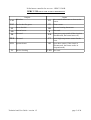
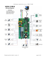
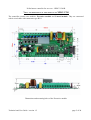
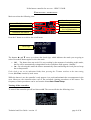
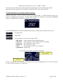
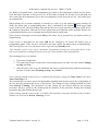
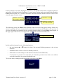
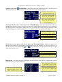
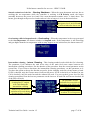
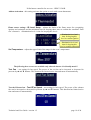
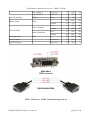
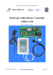
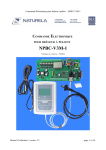
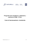
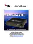
Pellet burner controller for an oven – NPBC-V3M-B
Electronic Controller
for Pellet Oven
NPBC-VM3-B
SOFTWARE VERSION 1.7/1.7
Technical and User Guide / version 1.5
page 1 of 24
Pellet burner controller for an oven – NPBC-V3M-B
INTRODUCTION
The controller NPBC-V3M-B is designed to run burners, that use a photo sensor to detect the
burning fire. It measures the level of illumination from the burning fire. The pulsing control of the
auger motor from the pellet tank allows the precise dosing of the amount of pellets that goes to the
burner. NPBC-V3M-B is able to control an optional internal auger motor that forwards the pellets
inside the burner. The controller runs two blowers: one that provides the air to the burning chamber
and the other one is an additional fan, for example, for taking out the exhaust gases, if necessary. The
power settings for the main air fan are applicable for both of the blowers at the same time and depend
on the amount of needed fresh air in the burner. An additional powerful blower could also be
connected to the controller to blow away the ashes from the burning chamber during the cleaning
procedures. All of the controlled mechanisms must work on 220VAC or 110VAC mains power
supply!
Main advantages of the controller:
•
Settings for all of the ignition and burning processes parameters
•
RS-232 interface for PC for remote monitoring, control or software upgrade.
•
Supports date and time
•
Full hardware and sensors self diagnostic. If a problem occurs, a short message with the reason
appears and, if necessary, the work mode automatically changes.
•
An option to set up automatic clean-ups, providing independent continuous performance with
no attendance needed.
•
Automatic three-level power regulation for reaching the set temperature in the oven and an
additional temporary Suspend mode to avoid ignition and extinction cycles during temporary
reduction of needed energy.
MECHANISMS AND SENSORS THAT COULD BE CONNECTED TO NPBC-V3M-B
•
•
•
•
•
•
•
•
•
•
Electric feed screw motor to transfer pellets from the bunker to the burner (power up to 180W)
Electric internal auger motor to forward the fuel to the burning area (power up to 180W)
Main blower with smooth speed control to regulate the air flow (power up to 180W)
Cleaner motor - an additional high power blower to clean the burner ( power up to 800W)
A blower for the flue gases (power up to 180W)
Heater for firing the pellets ( power up to 550W)
(Optional) Frequency inverter to power up a powerful air fan
Photo sensor to detect ignition
Thermostat to control the backfire
pt100 high temperature sensor for the oven
Technical and User Guide / version 1.5
page 2 of 24
Pellet burner controller for an oven – NPBC-V3M-B
NPBC-V3M INPUTS AND OUTPUTS DESCRIPTION:
Outputs
RT
An external thermostat to decrease the
power
FSG Fan for the flue gases
PS
Photo sensor
SF
Screw for fuel
RB
Reverse burning thermostat
SB
Internal screw
B
PH
Not used
WH
Emergency stop switch (if the circuit is
disconnected, the burner turns off)
PWH Not used
PT
pt100 high temperature sensor for the
oven
IGN Ignition heater
OD
Open door sensor (if the circuit is
disconnected, the burner works in
Suspend mode)
FM
FC
Main fan
Inputs
Fan for cleaning
Technical and User Guide / version 1.5
Not used
LED Not used
page 3 of 24
Pellet burner controller for an oven – NPBC-V3M-B
Technical and User Guide / version 1.5
page 4 of 24
Pellet burner controller for an oven – NPBC-V3M-B
VIEW AND DIMENSIONS OF THE MODULES OF NPBC-V3M
The controller consists two modules: Executive module and Control module. They are connected
with 4 wired cable with connectors type RJ11
Dimensions and mounting holes of the Executive module
Technical and User Guide / version 1.5
page 5 of 24
Pellet burner controller for an oven – NPBC-V3M-B
External dimensions of the Control module in a housing box
The control module could be mounted on a wall, by using 2 screws vertically placed on 60 mm from
each other with size of the head between 5 mm and 7.8 mm.
Technical and User Guide / version 1.5
page 6 of 24
Pellet burner controller for an oven – NPBC-V3M-B
NPBC-V3M-B TECHNICAL SPECIFICATION
1
Number of inputs
6
2
Temperature sensors type
pt100
3
Maximum measuring temperature
350°C
4
Detecting ignition
By a photo sensor
5
Temperature measuring accuracy
1%
6
Number of outputs
6
7
Supply voltage of each output
power supply voltage
8
Type of the motors of the air fan and the flue gases fan
induction motor with power
up to 180W
9
Ignition heater maximum power
550W
10
Additional cleaning blower maximum power
800W
11
Maximum power consumed by any other output
180W
12
Maximum short time current on each output
16A AC
13
Maximum section of the plugged in cables in each terminal
2.5mm2
14
Serial interface RS-232
Yes, with connector DB9
15
Power supply voltage
90-250V AC
16
Power consumed in Standby mode
<1W
17
Executive module PCB dimensions
180х90mm
18
Control module PCB dimensions
104х75mm
19
Maximum length of the connecting wire between Executive
module and Control module
up to 40m
Technical and User Guide / version 1.5
page 7 of 24
Pellet burner controller for an oven – NPBC-V3M-B
EXPLOITATION
INSTRUCTIONS
Main screen has the following view:
Work phase
Fuel screw motor
Air fan
Additional information
Internal screw motor
Work phase
Temperature in the oven
Flame indicator and
level of illumination
Clock
Press the F button to switch to the on/off menu:
Check sign
The buttons ▲ and ▼ move up or down the check sign, which indicates the mode you are going to
select. Press the F button again to select the mode.
•
•
Off – The burner does not work. If it was working by the moment of switching to this mode,
the fire will be automatically extinguished. In the work phase field appears „Standby”.
On – By selecting this mode the burner automatically starts and during the work process keeps
the set temperature.
If the clock is not set (its indication blinks) then pressing the F button switches to the time setting
screen (Set Time) instead of mode menu.
While the burner is on, the controller’s only purpose is to reach and maintain the set temperature in the
oven. Moreover, the controller takes care of the periodical cleaning procedures of the burner. The
frequency of these procedures can be set from the menu Auto Clean Setup.
Turning off the controller:
To turn off the controller press F and choose Off. The screen will take the following view:
Technical and User Guide / version 1.5
page 8 of 24
Pellet burner controller for an oven – NPBC-V3M-B
The controller automatically goes through the extinguishing the fire and cleaning procedures.
Remember that the complete extinction and cleaning the burner after that takes time.
General information for operating with the controller:
When the controller’s screen is in base position, by pressing the ▲ (+) or ▼(-) buttons you enter in a
mode for changing the temperature. Confirm and remember the settings by pressing the ↵ (Enter)
button or automatically by pressing no buttons for 6 seconds.
Press the Enter button to switch the additional information in the bottom left side of the screen:
set temperature
current date
error messages, if any. Error messages can be:
•
•
•
•
•
•
BB Alarm
Sensor E1
Sensor E2
Open Door
Frost
IgnitionFail
- alarm from the back burning thermistor
- the temperature sensor is disconnected or missing
- the temperature sensor is short
- the oven's door is open
- the temperature in the oven is negative
- ignition fail
View of the screen when a problem is registered:
Sign for a problem in
the controller
Description of the
problem(s)
If there is a sign „Е“ in the top right corner of the screen, press the Enter button to check the problem
up. The possible messages are listed above.
Technical and User Guide / version 1.5
page 9 of 24
Pellet burner controller for an oven – NPBC-V3M-B
WORKING METHOD
While working, the burner goes through several stages: cleaning, igniting, burning, extinguishing,
cleaning again and initial state.
Every ignition begins with a cleaning cycle, which is indicated by a symbol for a fan
in the upper
right corner of the screen (field work phase). The purpose is to clean all leftovers of the previous
burning. At first, for a certain time, set in the Cleaning on Start menu, only the primary fan works and
after that the additional cleaning fan turns on, if there is any and if it is not set off. After that the burner
goes to igniting phase.
The igniting is indicated by the symbol
in the upper right corner of the screen (field work phase).
A portion of pellets, which are going to be ignited by the electrical heater and the fan, are loaded.
When the flame sensor indicates the pellets are burning, a symbol
appears in the flame indicator
field and the burner goes to burning phase. If the pellets do not ignite before the set time is up, a new
portion of pellets is loaded and a new attempt for ignition is made. When the maximum ignition retries
are made, the burner stops and a message Ignition fail appears.
The logic on igniting is as follows:
1. At first the heater turns on and works without air fan for the time set in the menu Cycle Setup,
line Heater. The purpose is to heat up faster. Should watch out for the heater not to get
overheated and damaged, if the time for turning on the cooling is too long!
2. At the same time, while turning on the heater, a dose of pellets is fed for so long as it is set in
the menu: General Setup , line Feed.
3. After the time for the heater, working without air fan, runs out, there are two more steps on
which the air fan turns on. The idea is that the air fan works less intensive at first, so that it
doesn't extinguish the fire, but only keeps the needed oxygen level. After the fire is steady, the
fan's speed can be increased for full igniting of all the pellets.
4. If the photo sensor detects enough light, which can be set from the menu IR Level Setup, line
Ign, the ignition cycle breaks off and the burner goes to burning phase. Two parameters are
used for recognizing the light level – level of illumination, measured by the photo sensor and
time the light is over this level.
5. If by the end of the ignition cycle, the fire doesn't start, a few more cycles are performed,
starting with pellet feeding and turning on the heater without air fan. Set the number of retries
from General Setup, line Retries.
6. If the fire doesn't start after all of the retries, an alarm Ignition Fail occurs and no more retries
are going to be performed.
The burning phase is indicated by any of the following symbols in the upper right corner of the screen:
,
,
or
. The burner works on its lowest power level indicated by
while going from
igniting to burning until the fire flares up. After that the burner goes on its second power level
indicated by . The time for the burner to work on these two power levels can be set from the menu
Burning Startup. After igniting phase, the power is regulated depending on the difference between
the temperature in the oven and the set temperature. Power regulation is on three levels with additional
level for suspending the fire. For each level you can set the fan speed, amount of pellets and frequency
of loading. When the difference in temperatures is smaller than the set temperature for the first power
level, the burner goes to Suspend mode. If the temperature in the oven is still increasing and gets
higher than the set temperature with as many degrees as set in the menu Overheating, the burner turns
Technical and User Guide / version 1.5
page 10 of 24
Pellet burner controller for an oven – NPBC-V3M-B
off. While in Suspend mode, if the temperature gets equal to the temperature needed for first power
level, the burner switches to first power level. If the burner is turned off, because of Overheating and
after some time the temperature gets to the set temperature for the first power level, the burner turns
on automatically.
When turning off, no matter manually or caused by a timer or by the input Emergency turning off
(WH), the burner goes to extinguishing phase. This is indicated by the symbol
in the upper right
corner of the screen. The fuel feeding stops and the fan runs on low speed for preventing a back fire to
the container with pellets, while the rest of the pellets burn out. When the sensor indicates that the fire
is quenched the burner goes to cleaning phase and after that in initial state.
If the circuit is interrupted on the input OD by the sensor for an opened door, the burner works on
Suspend mode.
If the circuit is interrupted on the input WH by the emergency off switch, the burner goes to
extinguishing phase. If the circuit is restored by the same switch, the burner turns on automatically.
While turning off in this case, the burner doesn't goes through Standby mode.
The controller can be set for up to 4 automatic intermediate cleanings for twenty four hours. At the
time set for automatic cleaning the burner turns off, cleans and then starts automatically.
The cleaning process is as follows:
1. The burner extinguishes.
2. The main blower turns on and works on maximum power for time set in the menu Cleaning
on Stop, line Fan.
3. After the above time is up, the additional fan turns on and works along with the main blower
for time set in the menu Cleaning on Stop, line Cleaner.
If this cleaning method is unnecessary, it could be deactivated by setting the Clean Count in the menu
Auto Clean Setup to 0.
The controller has one more option for intermediate cleanings that doesn't require the extinguishing of
the fire and only increases the power of the blower. The settings for this cleaning method are in the
menu Interm. Cleaning. The parameters for this setting are: the interval between the cleaning
procedure, blower's speed for the cleaning and the duration of the procedure. During this cleaning
procedures the pellet feeding doesn't stop.
If this cleaning method is unnecessary, it could be deactivated by setting the duration of the procedure
(middle row in the menu Interm. Cleaning) to 0 sec.
Technical and User Guide / version 1.5
page 11 of 24
Pellet burner controller for an oven – NPBC-V3M-B
USER SETTINGS
To enter settings mode press and hold the F button for 1.5 seconds. User settings are always available
no matter in what mode the burner is working at the moment.
When the controller is in settings mode, the buttons have the following functions:
•
The Enter button switches to the next editable field on the current screen, if any
•
▲ and ▼ buttons increase or decrease the current value. If you hold the button, the value
automatically changes in the relevant direction. If the setting requests a choice from a list of
options the button ▲ selects the next option and the button▼ the previous, if any.
•
The F button forwards to the next setting screen and if any of the parameters has been changed,
it confirms the new values. If this was the last setting screen the controller switches to the main
screen.
•
If no buttons have been pressed for awhile, the controller shows the main screen and ignores
the changes made on the current screen.
Manual control of the feed screw motor Manual Feed. By using the
up or down arrow keys turn on or off the check box in front of Feed. If
the check box is checked the screw motor works for 10 minutes or
until the check box is unchecked manually again. You can use this
option to load the screw motor if it was left empty on any reasons.
This menu is available only in Standby mode!!!
Time setting - Set Time
Sets the clock
Date setting - Set Date
Sets the date
Contrast
Sets the contrast of the LCD display
Language
Choose the language you prefer for the menus.
Technical and User Guide / version 1.5
page 12 of 24
Pellet burner controller for an oven – NPBC-V3M-B
FACTORY SETTINGS
Factory settings are used for adapting the controller to the specifics of the burner, the pellets which are
going to be used and the boiler installation. To enter factory settings mode press and hold the F and the
Enter buttons together for 3 seconds. Information about the hardware and the software version of the
controller appears on the screen:
Software version of
the executive module
Controller version
Software version of
the control module
The following pressing the Enter button forwards to the first screen with factory settings. Browse the
menus by pressing the arrow buttons: ▲ forwards to the next menu and ▼returns to the previous. If
you want to change the parameters in the currently displayed menu, press the Enter button again. In
the upper right corner of the screen appears the sign , which indicates the Edit mode:
Sign for Edit mode
In this mode the buttons have the following functions:
•
the arrow buttons ▲ or ▼change the value of the currently blinking parameter in the relevant
direction;
•
the Enter button switches to the next editable parameter;
•
the F button saves the changes in the current menu and exits the Edit mode;
•
if no buttons are pressed for a certain time, the controller goes back to its main screen without
saving the settings in the currently displayed menu.
To exit the factory settings press F and confirm your choice with Enter:
Technical and User Guide / version 1.5
page 13 of 24
Pellet burner controller for an oven – NPBC-V3M-B
Factory settings are as follows:
Cleaning on Start – set the work time for the main (Fan) and the additional (Cleaner) air fan for
the cleaning cycle before ignition
Cleaning on Stop – set the work time for the main (Fan) and the additional (Cleaner) air fan for the
cleaning cycle after extinction. These settings also apply for the intermediate automatic cleanings.
Cleaning after extinction caused by Back Burning alarm – Cleaning on BB – set the work time
for the main (Fan) and the additional (Cleaner) air fan for the cleaning cycle if a back burning alarm
has been registered.
General Setup - set the number of ignition attempts (Retries), the work time of the auger for
initial feed (Feed) and the speed of the Exhaust Fan (EFan).
Technical and User Guide / version 1.5
page 14 of 24
Pellet burner controller for an oven – NPBC-V3M-B
Ignition cycle setup Cycle Setup – adjusts the work time of the heater before the fan turns on
and the following two work modes of the fan, which include speed and duration.
The heater works for 10 sec.
before the fan turns on
After that, along with the
heater, the fan works for
60 sec. on 5% of its power
Next 3 min., along with the
heater, the fan works on
15% of its power
Waiting for the first dose of fuel to burn out – Initial Burning – After detecting that the pellets are
burning, the controller can wait for the fire to get steady. During this initial burning, no new pellets are
fed and only the air fan and the exhaust fan work. To activate this setting, enter the duration of this
initial burning process without feeding new pellets (Dur.) and the speed of the fans (Fan).
If this parameter is 0 sec.,
this process will be skipped
The exhaust fan's speed
The air fan's speed
Work time on lower power until the fire flares up – Burning Startup – Right after ignition, the
burner doesn't work on its full power to prevent extinction of the unsteady fire. At first it works on its
two lower power levels indicated by and
. From this menu you can set the work time for each
of these two power levels
Work time on first power level
Work time on second power level
Burn Level – sets limits for power regulation. Set the difference between the set temperature and the
temperature in the oven for each level.
If the temperature difference
is more than 10 degrees, the
burner works on its 3rd level
If the temperature difference is
between 0 and 5 degrees, the
burner works on its 1st level
Technical and User Guide / version 1.5
If the temperature difference is
between 5 and 10 degrees, the
burner works on its 2nd level
page 15 of 24
Pellet burner controller for an oven – NPBC-V3M-B
3rd level Setup – adjusts the work mode for 3rd power level (maximum power). Set the active
time of the auger when loading a portion of pellets, the cycle time before loading a new portion of
pellets and the fan speed.
This screen means the following: on 3rd power level, on every 30 seconds (Cycle), the auger loads
pellets for 5 seconds (Feed). The fans work on 100% of their power (Fan).
2nd level Setup - adjusts the work mode for 2nd power level. Set the active time of the auger
when loading a portion of pellets, the cycle time before loading a new portion of pellets and the fan
speed.
1st level - Setup - adjusts the work mode for 1st power level. Set the active time of the auger when
loading a portion of pellets, the cycle time before loading a new portion of pellets and the fan speed.
Suspend – adjusts the Suspend mode. Set the active time of the auger when loading a portion of
pellets, the cycle time before loading a new portion of pellets and the fan speed. Settings here are the
same as above.
Technical and User Guide / version 1.5
page 16 of 24
Pellet burner controller for an oven – NPBC-V3M-B
Smooth extinction of the fire – Burning Shutdown – When the room thermostat activates due to
reaching the set temperature while the controller is working in CH Priority mode, the burner
smoothly decreases the power level and if the room thermostat remains active, it shuts down. The
burner goes through each power level and works on it for as long as it is set in the menu below:
If the burner is working on
this power level, in 60 seconds
it will switch to the lower one
Overheating while in Suspend mode – Overheating – When the temperature in the oven gets equal
to the Set temperature, the burner switches to Suspend mode. If the temperature is still increasing
and gets higher than the set temperature with as many degrees as set in this menu, the burner turns off.
Intermediate cleaning – Interm. Cleaning – This cleaning method works while the fire is burning.
The parameter Cycle indicates the total active time of the main feed screw motor between two
intermediate cleaning procedures. Set the duration of the procedure from the second parameter on the
second line. If you want to deactivate the intermediate cleaning procedures, set this parameter to 0.
You have the option to choose the fan that you prefer for the cleaning: main fan, cleaner motor or both.
If CM is checked, only the Cleaner motor works on full power. If Fan is checked (or if neither Fan, nor
CM is checked), only the main fan and the exhaust fan work. You can set their power level for this
cleaning procedures from the last two parameters on the last row. If both CM and Fan are checked, all
of the fans will work.
The procedure will be
If the box is checked, the
performed on every 600 sec
cleaning fan (FC output)
work time of the fuel feeder
will work during the
The procedure lasts
intermediate cleaning
for 30 seconds
If the box is checked, the
If activated, the main fan will
main fan will work during
work on 75% of its power
the intermediate cleaning
Technical and User Guide / version 1.5
page 17 of 24
Pellet burner controller for an oven – NPBC-V3M-B
Automatic cleanings - Auto Clean Setup – The burner has an option for Automatic cleaning
procedures. During these procedures, the burner turns off, cleans itself and automatically turns on
again. The parameter in this menu indicates the burning time between the automatic cleaning
procedures. If the burner turns off between two cleaning procedures for some reason (for example, it
has reached the set temperature, or the thermostat has activated, or else), the timer until the next
procedure starts from 0 again.
Hardware Setup – gives the opportunity for turning off the internal auger motor (Burner Feeder)
and the additional cleaning fan (Cleaner Motor), if the burner does not have these options. If Tstat
NO is checked, the room thermostat will be with normally opened sockets.
Burner feeder active time set - Burner Feeder – adjusts the internal auger motor's (if any) active
time in percents, depending on the active time of the feed screw motor. For example, if the feed screw
motor works for 5 seconds for each cycle and this setting is 150%, then the internal auger motor will
start spinning at the same time with the feed screw motor, but it will stop not in 5 seconds, but in 7.5
seconds.
Percent of the feed screw
motor's active time
Additional constant time
Delay for the Cleaner motor – Cleaner – This menu sets a delay time after every cleaning procedure
which uses the FC output. The delay time is equal to the active time of the FC output. For example, if
you use this output for a mechanical actuator, during the cleaning procedures it will be supplied with
power to push out the ashes. After that the actuator will have time to get back to its normal position
before the new portion of pellets is loaded.
Technical and User Guide / version 1.5
page 18 of 24
Pellet burner controller for an oven – NPBC-V3M-B
Addons Activation – this setting activates the option to work with a room thermostat.
Flame sensor settings - IR Level Setup – adjusts the limits of the flame sensor for recognizing
ignition and extinction and the minimum time for keeping these rates to confirm the condition. Each
row’s format is: <illumination level>/<time for keeping this level>
Illumination level and
time for keeping this
level to confirm ignition
Illumination level and
time for keeping this
level to confirm extinction
Set Temperature – adjusts the upper limit of the range for the oven’s temperature
The following three screens are available only when the burner is in Standby mode!!!
Test Fan – test setting for fan speed. The power of the air fan can be increased or decreased in
percents by ▲ and ▼ buttons. This function has limited active time and turns off automatically.
Test the Exhaust fan – Test EFan Speed – test setting for fan's speed. The power of the exhaust
fan can be increased or decreased in percents by ▲ and ▼ buttons. This function has limited active
time and turns off automatically.
Technical and User Guide / version 1.5
page 19 of 24
Pellet burner controller for an oven – NPBC-V3M-B
Test Outputs – When a row is checked, power is supplied to this output for test purposes.
Setup parameters range for NPBC-V3M-B
Setup Menu
Parameter
Unit
Min
Contrast
Contrast
level
0
20
10
Fan
seconds
10
600
180
Cleaner
seconds
1
60
20
Fan
seconds
10
600
180
Cleaner
seconds
1
60
20
Fan
seconds
10
600
180
Cleaner
seconds
1
60
20
0
5
3
Cleaning on Start
Cleaning on Stop
Cleaning on BB
Retries
General Setup
Cycle Setup
Feed
seconds
1
99
10
EFan
speed level
1
100
15
Heater
seconds
0
600
00
speed level
1
100
5
10
600
60
speed level
1
100
15
minutes
1
9
3
Duration
seconds
0
300
0
Fan column 1
speed level
1
100
20
Fan column 2
speed level
1
100
20
1st level
seconds
10
600
60
2 level
seconds
10
600
60
dT for 3rd Burn Level °C
0
50
10
dT for 2nd Burn Level °C
0
49
5
dT for 1st Burn Level °C
0
48
0
Fan phase 1
Fan phase 2
Initial Burning
Burning Startup
Burn Level
3rd Burn Level Setup
Max Default
nd
seconds
Feed
seconds
0.1
25.0
5.0
Cycle
seconds
4
120
30
Fan column 1
speed level
1
100
100
Technical and User Guide / version 1.5
page 20 of 24
Pellet burner controller for an oven – NPBC-V3M-B
1
100
100
seconds
0.1
25.0
3.0
Cycle
seconds
4
120
30
Fan column 1
speed level
1
100
50
Fan column 2
speed level
1
100
50
Feed
seconds
0.1
25.0
3.0
Cycle
seconds
4
120
20
Fan column 1
speed level
1
100
25
Fan column 2
speed level
1
100
25
Feed
seconds
0.1
25.0
2.0
Cycle
seconds
10
120
120
Fan column 1
speed level
1
100
5
Fan column 2
speed level
1
100
5
3rd Power Level
seconds
10
300
60
2nd Power Level
seconds
10
300
60
1st Power Level
seconds
10
300
60
Overheating
Max
°C
0
50
25
Interm. Cleaning
Cycle
seconds
10
900
600
Duration
seconds
0
120
30
2nd Burn Level Setup
1st Burn Level Setup
Suspend Burn Level
Burning Shutdown
Fan column 2
speed level
Feed
Technical and User Guide / version 1.5
page 21 of 24
Pellet burner controller for an oven – NPBC-V3M-B
Fan, column 1
speed level
1
100
75
Fan, column 2
speed level
1
100
75
Auto Clean Setup
Cycle
hours
0
24
2
Burner Feeder
Duty
110
500
150
seconds
0
30
0
level
1
150
100
10
240
20
0
150
40
seconds
10
240
60
°C
50
250
300
Detect Ignition
IR Level Setup
Detect Extinction
Set Temperature
Max
%
seconds
level
Test Fan Speed
speed level
0
100
0
Test EFan Speed
speed level
0
100
0
NPBC_Monitor.exe NPBC-V3M monitoring software
Technical and User Guide / version 1.5
page 22 of 24
Pellet burner controller for an oven – NPBC-V3M-B
Setting the parameters with NPBC_Monitor.exe
Technical and User Guide / version 1.5
page 23 of 24
Pellet burner controller for an oven – NPBC-V3M-B
Technical and User Guide / version 1.5
page 24 of 24