1
User’s Manual
Qosmio G40
Table of Contents
Copyright. . . . . . . . . . . . . . . . . . . . . . . . . . . . . . . . . . . . . . . . . . . . . . . . . vii
Disclaimer . . . . . . . . . . . . . . . . . . . . . . . . . . . . . . . . . . . . . . . . . . . . . . . . vii
Trademarks . . . . . . . . . . . . . . . . . . . . . . . . . . . . . . . . . . . . . . . . . . . . . . viii
Macrovision License . . . . . . . . . . . . . . . . . . . . . . . . . . . . . . . . . . . . . . viii
FCC information . . . . . . . . . . . . . . . . . . . . . . . . . . . . . . . . . . . . . . . . . . . ix
EU Declaration of Conformity . . . . . . . . . . . . . . . . . . . . . . . . . . . . . . . . . x
VCCI Class B Information . . . . . . . . . . . . . . . . . . . . . . . . . . . . . . . . . . . . x
Important Safety Information for Computers with TV tuner . . . . . . . . . x
Modem warning notice. . . . . . . . . . . . . . . . . . . . . . . . . . . . . . . . . . . . . . xi
Japan regulations . . . . . . . . . . . . . . . . . . . . . . . . . . . . . . . . . . . . . . . . . . xii
Instructions for IC CS-03 certified equipment . . . . . . . . . . . . . . . . . . xiv
Notes for Users in Australia and New Zealand . . . . . . . . . . . . . . . . . . xv
Optical disc drive safety instructions. . . . . . . . . . . . . . . . . . . . . . . . . xix
International precautions. . . . . . . . . . . . . . . . . . . . . . . . . . . . . . . . . . . xxi
Preface
Conventions . . . . . . . . . . . . . . . . . . . . . . . . . . . . . . . . . . . . . . . . . . . . xxiii
General Precautions
Creating a computer-friendly environment . . . . . . . . . . . . . . . . . . . xxvi
Stress injury . . . . . . . . . . . . . . . . . . . . . . . . . . . . . . . . . . . . . . . . . . . . xxvi
Heat injury . . . . . . . . . . . . . . . . . . . . . . . . . . . . . . . . . . . . . . . . . . . . . . xxvii
Pressure or impact damage. . . . . . . . . . . . . . . . . . . . . . . . . . . . . . . . xxvii
PC Card overheating . . . . . . . . . . . . . . . . . . . . . . . . . . . . . . . . . . . . . xxvii
Mobile phones . . . . . . . . . . . . . . . . . . . . . . . . . . . . . . . . . . . . . . . . . . xxvii
Instruction Manual for Safety and Comfort . . . . . . . . . . . . . . . . . . . xxvii
The cautions on use of a Qosmio G40 series computer . . . . . . . xxviii
Chapter 1
Introduction
Equipment checklist. . . . . . . . . . . . . . . . . . . . . . . . . . . . . . . . . . . . . . . 1-1
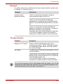
Hardware . . . . . . . . . . . . . . . . . . . . . . . . . . . . . . . . . . . . . . . . . . . . . . . . 1-3
Special features . . . . . . . . . . . . . . . . . . . . . . . . . . . . . . . . . . . . . . . . . 1-12
TOSHIBA Value Added Package . . . . . . . . . . . . . . . . . . . . . . . . . . . . 1-14
Utilities and Applications. . . . . . . . . . . . . . . . . . . . . . . . . . . . . . . . . . 1-15
User’s Manual
ii
Qosmio G40
Options . . . . . . . . . . . . . . . . . . . . . . . . . . . . . . . . . . . . . . . . . . . . . . . . 1-17
Chapter 2
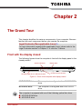
The Grand Tour
Front with the display closed . . . . . . . . . . . . . . . . . . . . . . . . . . . . . . . 2-1
Left side . . . . . . . . . . . . . . . . . . . . . . . . . . . . . . . . . . . . . . . . . . . . . . . . . 2-2
Right side . . . . . . . . . . . . . . . . . . . . . . . . . . . . . . . . . . . . . . . . . . . . . . . 2-4
Back . . . . . . . . . . . . . . . . . . . . . . . . . . . . . . . . . . . . . . . . . . . . . . . . . . . . 2-6
Underside . . . . . . . . . . . . . . . . . . . . . . . . . . . . . . . . . . . . . . . . . . . . . . . 2-8
Front with the display open . . . . . . . . . . . . . . . . . . . . . . . . . . . . . . . . . 2-9
System indicators. . . . . . . . . . . . . . . . . . . . . . . . . . . . . . . . . . . . . . . . 2-12
Optical disc drives . . . . . . . . . . . . . . . . . . . . . . . . . . . . . . . . . . . . . . . 2-15
AC adaptor . . . . . . . . . . . . . . . . . . . . . . . . . . . . . . . . . . . . . . . . . . . . . 2-19
Chapter 3
Getting Started
Connecting the AC adaptor . . . . . . . . . . . . . . . . . . . . . . . . . . . . . . . . . 3-2
Opening the display . . . . . . . . . . . . . . . . . . . . . . . . . . . . . . . . . . . . . . . 3-4
Turning on the power . . . . . . . . . . . . . . . . . . . . . . . . . . . . . . . . . . . . . . 3-5
Starting up for the first time . . . . . . . . . . . . . . . . . . . . . . . . . . . . . . . . 3-6
Turning off the power . . . . . . . . . . . . . . . . . . . . . . . . . . . . . . . . . . . . . . 3-6
Restarting the computer . . . . . . . . . . . . . . . . . . . . . . . . . . . . . . . . . . 3-10
System Recovery Options . . . . . . . . . . . . . . . . . . . . . . . . . . . . . . . . . 3-10
System Recovery . . . . . . . . . . . . . . . . . . . . . . . . . . . . . . . . . . . . . . . . 3-11
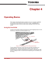
Chapter 4
Operating Basics
Using the Touch Pad . . . . . . . . . . . . . . . . . . . . . . . . . . . . . . . . . . . . . . 4-1
AV Controller. . . . . . . . . . . . . . . . . . . . . . . . . . . . . . . . . . . . . . . . . . . . . 4-2
Using the Fingerprint Sensor . . . . . . . . . . . . . . . . . . . . . . . . . . . . . . . 4-3
Web Camera . . . . . . . . . . . . . . . . . . . . . . . . . . . . . . . . . . . . . . . . . . . . 4-10
Using HD DVD-ROM drive and HD DVD-R drives . . . . . . . . . . . . . . 4-11
HD DVD . . . . . . . . . . . . . . . . . . . . . . . . . . . . . . . . . . . . . . . . . . . . . . . . 4-15
Writing CD/DVD/HD DVDs on HD DVD-R drives . . . . . . . . . . . . . . . 4-16
Media care . . . . . . . . . . . . . . . . . . . . . . . . . . . . . . . . . . . . . . . . . . . . . . 4-25
TV Tuner . . . . . . . . . . . . . . . . . . . . . . . . . . . . . . . . . . . . . . . . . . . . . . . 4-26
Sound system . . . . . . . . . . . . . . . . . . . . . . . . . . . . . . . . . . . . . . . . . . . 4-28
Modem . . . . . . . . . . . . . . . . . . . . . . . . . . . . . . . . . . . . . . . . . . . . . . . . . 4-30
Wireless communications . . . . . . . . . . . . . . . . . . . . . . . . . . . . . . . . . 4-34
LAN . . . . . . . . . . . . . . . . . . . . . . . . . . . . . . . . . . . . . . . . . . . . . . . . . . . 4-37
Cleaning the computer. . . . . . . . . . . . . . . . . . . . . . . . . . . . . . . . . . . . 4-39
Moving the computer . . . . . . . . . . . . . . . . . . . . . . . . . . . . . . . . . . . . . 4-39
Chapter 5
The Keyboard
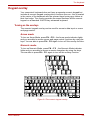
Typewriter keys. . . . . . . . . . . . . . . . . . . . . . . . . . . . . . . . . . . . . . . . . . .
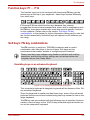
Function keys: F1 … F12 . . . . . . . . . . . . . . . . . . . . . . . . . . . . . . . . . .
Soft keys: FN key combinations . . . . . . . . . . . . . . . . . . . . . . . . . . . . .
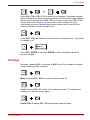
Hot keys. . . . . . . . . . . . . . . . . . . . . . . . . . . . . . . . . . . . . . . . . . . . . . . . .
Windows special keys . . . . . . . . . . . . . . . . . . . . . . . . . . . . . . . . . . . . .
Keypad overlay . . . . . . . . . . . . . . . . . . . . . . . . . . . . . . . . . . . . . . . . . . .
User’s Manual
5-1
5-2
5-2
5-3
5-5
5-6
iii
Qosmio G40
Generating ASCII characters . . . . . . . . . . . . . . . . . . . . . . . . . . . . . . . . 5-7
Chapter 6
Power
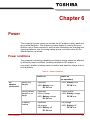
Power conditions . . . . . . . . . . . . . . . . . . . . . . . . . . . . . . . . . . . . . . . . . 6-1
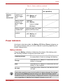
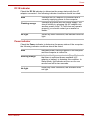
Power indicators. . . . . . . . . . . . . . . . . . . . . . . . . . . . . . . . . . . . . . . . . . 6-2
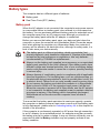
Battery types. . . . . . . . . . . . . . . . . . . . . . . . . . . . . . . . . . . . . . . . . . . . . 6-4
Care and use of the battery pack . . . . . . . . . . . . . . . . . . . . . . . . . . . . 6-6
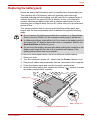
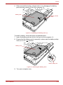
Replacing the battery pack . . . . . . . . . . . . . . . . . . . . . . . . . . . . . . . . 6-11
TOSHIBA Password Utility. . . . . . . . . . . . . . . . . . . . . . . . . . . . . . . . . 6-13
Starting the computer by password . . . . . . . . . . . . . . . . . . . . . . . . . 6-14
Power-up modes. . . . . . . . . . . . . . . . . . . . . . . . . . . . . . . . . . . . . . . . . 6-15
Panel power on/off . . . . . . . . . . . . . . . . . . . . . . . . . . . . . . . . . . . . . . . 6-15
System Auto Off . . . . . . . . . . . . . . . . . . . . . . . . . . . . . . . . . . . . . . . . . 6-16
Chapter 7
HW Setup & BIOS Setup
Accessing HW Setup . . . . . . . . . . . . . . . . . . . . . . . . . . . . . . . . . . . . . . 7-1
HW Setup window . . . . . . . . . . . . . . . . . . . . . . . . . . . . . . . . . . . . . . . . 7-1
BIOS Setup Program . . . . . . . . . . . . . . . . . . . . . . . . . . . . . . . . . . . . . . 7-7
Chapter 8
AV functions
Media Center . . . . . . . . . . . . . . . . . . . . . . . . . . . . . . . . . . . . . . . . . . . . . 8-1
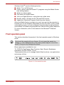
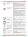
Front operation panel. . . . . . . . . . . . . . . . . . . . . . . . . . . . . . . . . . . . . . 8-2
Qosmio AV Controller . . . . . . . . . . . . . . . . . . . . . . . . . . . . . . . . . . . . . 8-5
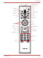
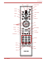
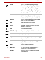
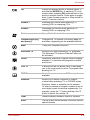
Remote Controller . . . . . . . . . . . . . . . . . . . . . . . . . . . . . . . . . . . . . . . . 8-6
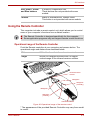
Using the Remote Controller . . . . . . . . . . . . . . . . . . . . . . . . . . . . . . . 8-11
Installing/Removing batteries . . . . . . . . . . . . . . . . . . . . . . . . . . . . . . 8-12
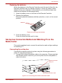
Set-top box Connection Method and Watching TV
on the Media Center . . . . . . . . . . . . . . . . . . . . . . . . . . . . . . . . . . . . . . 8-14
Connecting the Video devices. . . . . . . . . . . . . . . . . . . . . . . . . . . . . . 8-17
QosmioEngine . . . . . . . . . . . . . . . . . . . . . . . . . . . . . . . . . . . . . . . . . . 8-18
Chapter 9
Optional Devices
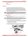
PC Card . . . . . . . . . . . . . . . . . . . . . . . . . . . . . . . . . . . . . . . . . . . . . . . . . 9-2
ExpressCard . . . . . . . . . . . . . . . . . . . . . . . . . . . . . . . . . . . . . . . . . . . . . 9-3
Bridge media slot . . . . . . . . . . . . . . . . . . . . . . . . . . . . . . . . . . . . . . . . . 9-5
Memory expansion . . . . . . . . . . . . . . . . . . . . . . . . . . . . . . . . . . . . . . . 9-10
Battery Packs . . . . . . . . . . . . . . . . . . . . . . . . . . . . . . . . . . . . . . . . . . . 9-14
Universal AC Adaptor . . . . . . . . . . . . . . . . . . . . . . . . . . . . . . . . . . . . 9-14
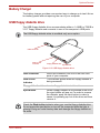
Battery Charger . . . . . . . . . . . . . . . . . . . . . . . . . . . . . . . . . . . . . . . . . 9-15
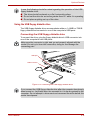
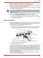
USB floppy diskette drive . . . . . . . . . . . . . . . . . . . . . . . . . . . . . . . . . 9-15
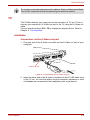
External monitor . . . . . . . . . . . . . . . . . . . . . . . . . . . . . . . . . . . . . . . . . 9-17
TV . . . . . . . . . . . . . . . . . . . . . . . . . . . . . . . . . . . . . . . . . . . . . . . . . . . . . 9-18
HDMI . . . . . . . . . . . . . . . . . . . . . . . . . . . . . . . . . . . . . . . . . . . . . . . . . . 9-20
S-Video-in . . . . . . . . . . . . . . . . . . . . . . . . . . . . . . . . . . . . . . . . . . . . . . 9-21
i.LINK (IEEE1394). . . . . . . . . . . . . . . . . . . . . . . . . . . . . . . . . . . . . . . . 9-22
Security lock . . . . . . . . . . . . . . . . . . . . . . . . . . . . . . . . . . . . . . . . . . . . 9-24
User’s Manual
iv
Qosmio G40
Chapter 10
Troubleshooting
Problem solving process . . . . . . . . . . . . . . . . . . . . . . . . . . . . . . . . . . 10-1
Hardware and system checklist . . . . . . . . . . . . . . . . . . . . . . . . . . . . 10-3
TOSHIBA support . . . . . . . . . . . . . . . . . . . . . . . . . . . . . . . . . . . . . . . 10-26
Chapter 11
Legal Footnotes
CPU*1. . . . . . . . . . . . . . . . . . . . . . . . . . . . . . . . . . . . . . . . . . . . . . . . . .
Memory (Main System)*2 . . . . . . . . . . . . . . . . . . . . . . . . . . . . . . . . . .
Battery Life*3 . . . . . . . . . . . . . . . . . . . . . . . . . . . . . . . . . . . . . . . . . . .
Hard Disk Drive (HDD) Capacity*4 . . . . . . . . . . . . . . . . . . . . . . . . . .
General HD DVD technology and playback*5 . . . . . . . . . . . . . . . . .
LCD*6. . . . . . . . . . . . . . . . . . . . . . . . . . . . . . . . . . . . . . . . . . . . . . . . . .
Graphics Processor Unit ("GPU”)*7 . . . . . . . . . . . . . . . . . . . . . . . . .
Wireless LAN*8 . . . . . . . . . . . . . . . . . . . . . . . . . . . . . . . . . . . . . . . . . .
Non-applicable Icons*9 . . . . . . . . . . . . . . . . . . . . . . . . . . . . . . . . . . .
Copy Protection*10 . . . . . . . . . . . . . . . . . . . . . . . . . . . . . . . . . . . . . .
TV Tuner*11 . . . . . . . . . . . . . . . . . . . . . . . . . . . . . . . . . . . . . . . . . . . . .
Images*12 . . . . . . . . . . . . . . . . . . . . . . . . . . . . . . . . . . . . . . . . . . . . . .
LCD Brightness and Eye Stain*13. . . . . . . . . . . . . . . . . . . . . . . . . . .
Safety Use for TV Tuner*14 . . . . . . . . . . . . . . . . . . . . . . . . . . . . . . . .
Appendix A
11-1
11-2
11-3
11-3
11-3
11-4
11-4
11-4
11-5
11-5
11-5
11-5
11-5
11-5
Specifications
Physical Dimensions . . . . . . . . . . . . . . . . . . . . . . . . . . . . . . . . . . . . . . A-1
Appendix B
Display Controller and Video modes
Display controller . . . . . . . . . . . . . . . . . . . . . . . . . . . . . . . . . . . . . . . . . B-1
Video modes . . . . . . . . . . . . . . . . . . . . . . . . . . . . . . . . . . . . . . . . . . . . . B-1
Appendix C
AT Commands
Appendix D
S-registers
S-register values. . . . . . . . . . . . . . . . . . . . . . . . . . . . . . . . . . . . . . . . . . D-1
AT command set result codes. . . . . . . . . . . . . . . . . . . . . . . . . . . . . . . D-5
Appendix E
V.90
V.90 mode . . . . . . . . . . . . . . . . . . . . . . . . . . . . . . . . . . . . . . . . . . . . . . . E-1
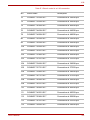
AT Command. . . . . . . . . . . . . . . . . . . . . . . . . . . . . . . . . . . . . . . . . . . . . E-3
Appendix F
Wireless LAN
Card Specifications . . . . . . . . . . . . . . . . . . . . . . . . . . . . . . . . . . . . . . . F-1
Radio Characteristics. . . . . . . . . . . . . . . . . . . . . . . . . . . . . . . . . . . . . . F-2
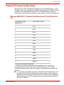
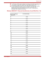
Supported Frequency Sub-bands . . . . . . . . . . . . . . . . . . . . . . . . . . . . F-3
Appendix G
Bluetooth wireless technology Interoperability
Bluetooth wireless technology and your Health . . . . . . . . . . . . . . . . G-3
Regulatory statements . . . . . . . . . . . . . . . . . . . . . . . . . . . . . . . . . . . . . G-3
Using Bluetooth® Card from TOSHIBA equipment in Japan . . . . . . G-5
Appendix H
AC Power Cord and Connectors
Certification agencies . . . . . . . . . . . . . . . . . . . . . . . . . . . . . . . . . . . . . H-1
User’s Manual
v
Qosmio G40
Appendix I
Usage Restrictions
Glossary
Index
User’s Manual
vi
Qosmio G40
Copyright
© 2007 by TOSHIBA Corporation. All rights reserved. Under the copyright
laws, this manual cannot be reproduced in any form without the prior
written permission of TOSHIBA. No patent liability is assumed, with respect
to the use of the information contained herein.
TOSHIBA Qosmio G40 Portable Personal Computer User’s Manual
First edition May 2007
Copyright authority for music, movies, computer programs, databases and
other intellectual property covered by copyright laws belongs to the author
or to the copyright owner. Copyrighted material can be reproduced only for
personal use or use within the home. Any other use beyond that stipulated
above (including conversion to digital format, alteration, transfer of copied
material and distribution on a network) without the permission of the
copyright owner is a violation of copyright or author's rights and is subject
to civil damages or criminal action. Please comply with copyright laws in
making any reproduction from this manual.
Please note that you may infringe the owner's rights protected by the
copyright laws if you use the screen mode switching functions (e.g. Wide
mode, Wide Zoom mode, etc.) of this product to display enlarged
images/video at coffee shops or hotels for the purposes of profits or
providing these to the public.
Disclaimer
This manual has been validated and reviewed for accuracy. The
instructions and descriptions it contains are accurate for the TOSHIBA
Qosmio G40 Portable Personal Computer at the time of this manual’s
production. However, succeeding computers and manuals are subject to
change without notice. TOSHIBA assumes no liability for damages incurred
directly or indirectly from errors, omissions or discrepancies between the
computer and the manual.
User’s Manual
vii
Qosmio G40
Trademarks
IBM is a registered trademark and IBM PC is a trademark of International
Business Machines Corporation.
Intel, Intel SpeedStep, Intel Core, Celeron and Centrino are trademarks or
registered trademarks of Intel Corporation.
Windows and Microsoft are registered trademarks and Windows Vista is a
trademark of Microsoft Corporation.
Photo CD is a trademark of Eastman Kodak.
Bluetooth is a trademark or registered trademark owned by its proprietor
and used by TOSHIBA under license.
Memory Stick is a registered trademark and i.LINK is a trademark of Sony
Corporation.
DVD MovieFactory is a registered trademarks of Ulead Systems, Inc.
Manufactured under license from Dolby Laboratories.
Dolby and the double-D symbol are trademarks of Dolby Laboratories.
Dolby Home Theater is a trademark of Dolby Laboratories.
EdgeMotion, PalmCheck, TouchPad and Synaptics are trademarks or
registered trademarks of Synaptics Incorporated.
Other trademarks and registered trademarks not listed above may be used
in this manual.
Macrovision License
This product includes copyright protection technology and intellectual
property that are patented in the U.S. and other countries. These patents
are the property of Macrovision Corporation. The use of copyright
protection must be authorized by Macrovision Corporation. It is intended for
home and other restricted-use applications, unless Macrovision
Corporation expressly authorizes otherwise. All forms of reverse
engineering or decompiling are forbidden.
User’s Manual
viii
Qosmio G40
FCC information
FCC notice "Declaration of Conformity Information"
This equipment has been tested and found to comply with the limits for a
Class B digital device, pursuant to part 15 of the FCC rules. These limits
are designed to provide reasonable protection against harmful interference
in a residential installation. This equipment generates, uses and can
radiate radio frequency energy and, if not installed and used in accordance
with the instructions, may cause harmful interference to radio
communications. However, there is no guarantee that interference will not
occur in a particular installation. If this equipment does cause harmful
interference to radio or television reception, which can be determined by
turning the equipment off and on, the user is encouraged to try to correct
the interference by one or more of the following measures:
■ Reorient or relocate the receiving antenna.
■ Increase the separation between the equipment and receiver.
■ Connect the equipment into an outlet on a circuit different from that to
which the receiver is connected.
■ Consult the dealer or an experienced radio/TV technician for help.
Only peripherals complying with the FCC class B limits may be attached to
this equipment. Operation with non-compliant peripherals or peripherals
not recommended by TOSHIBA is likely to result in interference to radio
and TV reception. Shielded cables must be used between the external
devices and the computer’s external monitor port, Universal Serial Bus
(USB 2.0) ports, i.LINK (IEEE1394) port, HDMI out port and microphone
jack. Changes or modifications made to this equipment, not expressly
approved by TOSHIBA or parties authorized by TOSHIBA could void the
user’s authority to operate the equipment.
FCC conditions
This device complies with part 15 of the FCC Rules. Operation is subject to
the following two conditions:
1. This device may not cause harmful interference.
2. This device must accept any interference received, including
interference that may cause undesired operation.
Contact
Address:
Telephone:
User’s Manual
TOSHIBA America Information Systems, Inc.
9740 Irvine Boulevard
Irvine, California 92618-1697
(949) 583-3000
ix
Qosmio G40
EU Declaration of Conformity
TOSHIBA declares that this product conforms to the following Standards:
Supplementary
Information:
“The product complies with the requirements of
the Low Voltage Directive 73/23/EEC, the EMC
Directive 89/336/EEC and/or the R&TTE
Directive 1999/5/EC.”
This product is carrying the CE-Mark in accordance with the related
European Directives. The party responsible for CE-Marking is TOSHIBA
Europe GmbH, Hammfelddamm 8, 41460 Neuss, Germany.
VCCI Class B Information
Important Safety Information for Computers with TV tuner
IEC60950-1/EN60950-1 Information technology equipment - Safety Coaxial cable connection to this computer must only be used if the cable
outer conductive shielding has been grounded by the cable installer at the
building premises as close to the point of cable entrance, or attachment, as
practicable and the connection complies with all local cable installation
requirements that are applicable in your area.
User’s Manual
x
Qosmio G40
Modem warning notice
This information is applicable to the models equipped with a built-in
modem.
Conformity Statement
The equipment has been approved to [Commission Decision “CTR21”] for
pan-European single terminal connection to the Public Switched Telephone
Network (PSTN).
However, due to differences between the individual PSTNs provided in
different countries/regions the approval does not, of itself, give an
unconditional assurance of successful operation on every PSTN network
termination point.
In the event of problems, you should contact your equipment supplier in the
first instance.
Network Compatibility Statement
This product is designed to work with, and is compatible with the following
networks. It has been tested to and found to conform with the additional
requirements conditional in EG 201 121.
Germany
ATAAB AN005,AN006,AN007,AN009,AN010
and DE03,04,05,08,09,12,14,17
Greece
ATAAB AN005,AN006 and GR01,02,03,04
Portugal
ATAAB AN001,005,006,007,011 and
P03,04,08,10
Spain
ATAAB AN005,007,012, and ES01
Switzerland
ATAAB AN002
All other countries/regions ATAAB AN003,004
Specific switch settings or software setup is required for each network,
please refer to the relevant sections of the user guide for more details.
The hookflash (timed break register recall) function is subject to separate
national type approvals. It has not been tested for conformity to national
type regulations, and no guarantee of successful operation of that specific
function on specific national networks can be given.
User’s Manual
xi
Qosmio G40
Japan regulations
Region selection
If you are using the computer in Japan, technical regulations described
under Telecommunications Business Law require that you select the Japan
region mode. It is illegal to use the modem in Japan with any other
selection.
Redial
Up to two redial attempts can be made. If more than two redial attempts are
made, the modem will return Black Listed. If you are experiencing
problems with the Black Listed code, set the interval between redials at one
minute or longer.
Japan’s Telecommunications Business Law permits up to two redials on
analogue telephones, but the redials must be made within a total of three
minutes.
The internal modem is approved by the Japan Approvals Institute for
Telecommunications Equipment.
A05-0413001
This label is located on the module.
User’s Manual
xii
Qosmio G40
Pursuant to FCC CFR 47, Part 68:
When you are ready to install or use the modem, call your local telephone
company and give them the following information:
■ The telephone number of the line to which you will connect the modem
■ The registration number that is located on the device
The FCC registration number of the modem will be found on either the
device which is to be installed, or, if already installed, on the bottom of the
computer, separate from the system information label.
■ The Ringer Equivalence Number (REN) of the modem, which can vary for the REN, please refer to the modem's label.
The modem connects to the telephone line by means of a standard jack
called the USOC RJ11C.
Type of service
Your modem is designed to be used on standard-device telephone lines.
Connection to telephone company-provided coin service (central office
implemented systems) is prohibited. Connection to party lines service is
subject to state tariffs. If you have any questions about your telephone line,
such as how many pieces of equipment you can connect to it, the
telephone company will provide this information upon request.
Telephone company procedures
The goal of the telephone company is to provide you with the best service it
can. In order to do this, it may occasionally be necessary for them to make
changes in their equipment, operations, or procedures. If these changes
might affect your service or the operation of your equipment, the telephone
company will give you notice in writing to allow you to make any changes
necessary to maintain uninterrupted service.
If problems arise
If any of your telephone equipment is not operating properly, you should
immediately remove it from your telephone line, as it may cause harm to
the telephone network. If the telephone company notes a problem, they
may temporarily discontinue service. When practical, they will notify you in
advance of this disconnection. If advance notice is not feasible, you will be
notified as soon as possible. When you are notified, you will be given the
opportunity to correct the problem and informed of your right to file a
complaint with the FCC. In the event repairs are ever needed on your
modem, they should be performed by TOSHIBA Corporation or an
authorized representative of TOSHIBA Corporation.
Disconnection
If you should ever decide to permanently disconnect your modem from its
present line, please call the telephone company and let them know of this
change.
User’s Manual
xiii
Qosmio G40
Fax branding
The Telephone Consumer Protection Act of 1991 makes it unlawful for any
person to use a computer or other electronic device to send any message
via a telephone fax machine unless such a message clearly contains in a
margin at the top or bottom of each transmitted page, or on the first page of
the transmission, the date and time it is sent, an identification of the
business, other entity or individual sending the message and the telephone
number of the sending machine or such business, other entity or individual.
In order to program this information into your fax modem, you should
complete the setup of your fax software before sending messages.
Instructions for IC CS-03 certified equipment
1. The Industry Canada label identifies certified equipment. This
certification means that the equipment meets certain
telecommunications network protective, operational and safety
requirements as prescribed in the appropriate Terminal Equipment
Technical Requirements document(s). The Department does not
guarantee the equipment will operate to the user’s satisfaction.
Before installing this equipment, users should ensure that it is
permissible to be connected to the facilities of the local
telecommunications company. The equipment must also be installed
using an acceptable method of connection.
The customer should be aware that compliance with the above
conditions may not prevent degradation of service in some situations.
Repairs to certified equipment should be coordinated by a
representative designated by the supplier. Any repairs or alterations
made by the user to this equipment, or equipment malfunctions, may
give the telecommunications company cause to request the user to
disconnect the equipment.
Users should ensure for their own protection that the electrical ground
connections of the power utility, telephone lines and internal metallic
water pipe system, if present, are connected together. This precaution
may be particularly important in rural areas.
Users should not attempt to make such connections themselves, but
should contact the appropriate electric inspection authority, or electrician,
as appropriate.
2. The user manual of analog equipment must contain the equipment’s
Ringer Equivalence Number (REN) and an explanation notice similar to
the following:
The Ringer Equivalence Number (REN) of the modem can vary - for the
REN, please refer to the modem's label.
User’s Manual
xiv
Qosmio G40
The Ringer Equivalence Number (REN) assigned to each terminal device
provides an indication of the maximum number of terminals allowed to be
connected to a telephone interface. The termination on an interface may
consist of any combination of devices subject only to the requirement that
the sum of the Ringer Equivalence Numbers of all the devices does not
exceed 5.
3. The standard connecting arrangement (telephone jack type) for this
equipment is jack type(s): USOC RJ11C.
The IC registration number of the modem is shown below.
Canada: 4005B-DELPHI
Notes for Users in Australia and New Zealand
Modem warning notice for Australia
Modems connected to the Australian telecoms network must have a valid
Austel permit. This modem has been designed to specifically configure to
ensure compliance with Austel standards when the country/region
selection is set to Australia. The use of other country/region settings while
the modem is attached to the Australian PSTN would result in your modem
being operated in a non-compliant manner. To verify that the
country/region is correctly set, enter the command ATI which displays the
currently active setting.
To set the country/region permanently to Australia, enter the following
command sequence:
AT%TE=1
ATS133=1
AT&F
AT&W
AT%TE=0
ATZ
Failure to set the modem to the Australia country/region setting as shown
above will result in the modem being operated in a non-compliant manner.
Consequently, there would be no permit in force for this equipment, with
the Telecoms Act 1991 prescribing a penalty of $12,000 for the connection
of non-permitted equipment.
User’s Manual
xv
Qosmio G40
Notes for use of this device in New Zealand
■ The grant of a Telepermit for a device in no way indicates Telecom
acceptance of responsibility for the correct operation of that device
under all operating conditions. In particular the higher speeds at which
this modem is capable of operating depend on a specific network
implementation which is only one of many ways of delivering high
quality voice telephony to customers. Failure to operate should not be
reported as a fault to Telecom.
■ In addition to satisfactory line conditions a modem can only work
properly if:
a/ It is compatible with the modem at the other end of the call, and;
b/ the application using the modem is compatible with the application
at the other end of the call - for example, accessing the Internet
requires suitable software in addition to a modem.
■ This equipment shall not be used in any manner which could constitute
a nuisance to other Telecom customers.
■ Some parameters required for compliance with Telecom’s PTC
Specifications are dependent on the equipment (PC) associated with
this modem. The associated equipment shall be set to operate within
the following limits for compliance with Telecom Specifications:
a/ There shall be no more than 10 call attempts to the same number
within any 30 minute period for any single manual call initiation, and;
b/ The equipment shall go on-hook for a period of not less than 30
seconds between the end of one attempt and the beginning of the
next, and;
c/ Automatic calls to different numbers shall be not less than 5
seconds apart.
■ Immediately disconnect this equipment should it become physically
damaged, and arrange for its disposal or repair.
■ The correct settings for use with this modem in New Zealand are as
follows:
ATB0 (CCITT operation)
AT&G2 (1800Hz guard tone)
AT&P1 (decadic dialing make-break ratio =33%/67%)
ATS0=0 (disable auto answer)
ATS6=4 (blind dial delay)
ATS7=Less than 90 (time to wait for carrier after dialing)
ATS10=Less than 150 (loss of carrier to hangup delay - the factory
default of 15 is recommended)
ATS11=90 (DTMF dialing on/off duration in milliseconds)
ATX2 (dial tone detect, but not USA call progress detect)
User’s Manual
xvi
Qosmio G40
■ When used in Auto Answer mode, the S0 register must be set with to a
value of either 3 or 4. This ensures:
■ a person calling your modem will hear a short burst of ringing before
the modem answers. This confirms that the call has been
successfully switched through the network.
■ caller identification information (which occurs between the first and
second ring cadences) is not destroyed.
■ The preferred method of dialing is to use DTMF tones (ATDT...) as this
is faster and more reliable than pulse (decadic) dialing. If for some
reason you must use decadic dialing, your communications program
must be set up to record numbers using the following translation table
as this modem does not implement the New Zealand “Reverse Dialing”
standard.
Number to be dialed: 0 1 2 3 4 5 6 7 8 9
Number to program into computer: 0 9 8 7 6 5 4 3 2 1
Note that where DTMF dialing is used, the numbers should be
entered normally.
■ The transmit level from this device is set at a fixed level and because of
this there may be circumstances where the performance is less than
optimal. Before reporting such occurrences as faults, please check the
line with a standard Telepermitted telephone, and only report a fault if
the phone performance is impaired.
■ It is recommended that this equipment be disconnected from the
Telecom line during electrical storms.
■ When relocating the equipment, always disconnect the Telecom line
connection before the power connection, and reconnect the power first.
■ This equipment may not be compatible with Telecom Distinctive Alert
cadences and services such as FaxAbility.
NOTE THAT FAULT CALLOUTS CAUSED BY ANY OF THE ABOVE
CAUSES MAY INCUR A CHARGE FROM TELECOM
User’s Manual
xvii
Qosmio G40
General conditions
As required by PTC 100, please ensure that this office is advised of any
changes to the specifications of these products which might affect
compliance with the relevant PTC Specifications.
The grant of this Telepermit is specific to the above products with the
marketing description as stated on the Telepermit label artwork. The
Telepermit may not be assigned to other parties or other products without
Telecom approval.
A Telepermit artwork for each device is included from which you may
prepare any number of Telepermit labels subject to the general instructions
on format, size and color on the attached sheet.
The Telepermit label must be displayed on the product at all times as proof
to purchasers and service personnel that the product is able to be
legitimately connected to the Telecom network.
The Telepermit label may also be shown on the packaging of the product
and in the sales literature, as required in PTC 100.
The charge for a Telepermit assessment is $337.50. An additional charge
of $337.50 is payable where an assessment is based on reports against
non-Telecom New Zealand Specifications. $112.50 is charged for each
variation when submitted at the same time as the original.
An invoice for $NZ1237.50 will be sent under separate cover.
Following information is only for EU-member states:
The use of the symbol indicates that this product may not be treated as
household waste. By ensuring this product is disposed of correctly, you will
help prevent potential negative consequences for the environment and
human health, which could otherwise be caused by inappropriate waste
handling of this product. For more detailed information about recycling of
this product, please contact your local city office, your household waste
disposal service or the shop where you purchased the product.
This symbol may not stick depending on the country and region where you
purchased.
User’s Manual
xviii
Qosmio G40
Optical disc drive safety instructions
Be sure to check the international precautions at the end of this section.
TOSHIBA
HD DVD-ROM drive TS-L802A
■ The HD DVD-ROM drive employs a laser system. To ensure proper
use of this product, please read this instruction manual carefully and
retain for future reference.
Should the unit ever require maintenance, contact an authorized
service location.
■ Use of controls, adjustments or the performance of procedures other
than those specified may result in hazardous radiation exposure.
■ To prevent direct exposure to the laser beam, do not try to open the
enclosure.
User’s Manual
xix
Qosmio G40
TOSHIBA
HD DVD-R drive SD-L902A
■ The HD DVD-R drive employs a laser system. To ensure proper use of
this product, please read this instruction manual carefully and retain for
future reference.
Should the unit ever require maintenance, contact an authorized
service location.
■ Use of controls, adjustments or the performance of procedures other
than those specified may result in hazardous radiation exposure.
■ To prevent direct exposure to the laser beam, do not try to open the
enclosure.
User’s Manual
xx
Qosmio G40
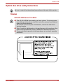
International precautions
CAUTION: This appliance contains a
laser system and is classified as a
“CLASS 1 LASER PRODUCT.” To use
this model properly, read the instruction
manual carefully and keep this manual
for your future reference. In case of any
trouble with this model, please contact
your nearest “AUTHORIZED service
station.” To prevent direct exposure to
the laser beam, do not try to open the
enclosure.
VORSICHT: Dieses Gerät enthält ein
Laser-System und ist als
“LASERSCHUTZKLASSE 1 PRODUKT”
klassifiziert. Für den richtigen Gebrauch
dieses Modells lesen Sie bitte die
Bedienungsanleitung sorgfältig durch
und bewahren diese bitte als Referenz
auf. Falls Probleme mit diesem Modell
auftreten, benachrichtigen Sie bitte die
nächste “autorisierte Service-Vertretung”.
Um einen direkten Kontakt mit dem
Laserstrahl zu vermeiden darf das Gerät
nicht geöffnet werden.
ADVARSEL: Denne mærking er anbragt
udvendigt på apparatet og indikerer, at
apparatet arbejder med laserstråler af
klasse 1, hviket betyder, at der anvendes
laserstrlier af svageste klasse, og at man
ikke på apparatets yderside kan bilve
udsat for utilladellg kraftig stråling.
APPARATET BOR KUN ÅBNES AF
FAGFOLK MED SÆRLIGT KENDSKAB
TIL APPARATER MED
LASERSTRÅLER!
Indvendigt i apparatet er anbragt den her
gengivne advarselsmækning, som
advarer imod at foretage sådanne
indgreb i apparatet, at man kan komme til
at udsatte sig for laserstråling.
User’s Manual
xxi
Qosmio G40
OBS! Apparaten innehåller
laserkomponent som avger laserstråining
överstigande gränsen för laserklass 1.
VAROITUS. Suojakoteloa si saa avata.
Laite sisältää laserdiodin, joka lähetää
näkymätöntä silmilie vaarallista
lasersäteilyä.
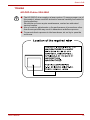
CAUTION: USE OF CONTROLS OR
ADJUSTMENTS OR PERFORMANCE
OF PROCEDURES OTHER THAN
THOSE SPECIFIED IN THE OWNER’S
MANUAL MAY RESULT IN
HAZARDOUS RADIATION EXPOSURE.
VORSICHT: DIE VERWENDUNG VON
ANDEREN STEURUNGEN ODER
EINSTELLUNGEN ODER DAS
DURCHFÜHREN VON ANDEREN
VORGÄNGEN ALS IN DER
BEDIENUNGSANLEITUNG
BESCHRIEBEN KÖNNEN
GEFÄHRLICHE
STRAHLENEXPOSITIONEN ZUR
FOLGE HABEN.
User’s Manual
xxii
Preface
Congratulations on your purchase of the Qosmio G40 series computer.
This powerful notebook computer provides excellent expansion capability,
includes multimedia functionality, and is designed to provide years of
reliable, high-performance computing.
This computer family includes a model with a built-in TV tuner. When you
wish to display a TV program or play CD/DVD with this model before
Windows starts, touch the TV panel or the CD/DVD panel (or the same
panels on the remote control) respectively during Windows startup. When
Windows is running, you can display or record a TV program using the My
TV feature of Media Center.
This manual tells how to set up and begin using your Qosmio G40
computer. It also provides detailed information on configuring your
computer, basic operations and care, using optional devices and
troubleshooting.
If you are a new user of computers or if you’re new to portable computing,
first read over the Introduction and The Grand Tour chapters to familiarize
yourself with the computer’s features, components and accessory devices.
Then read Getting Started for step-by-step instructions on setting up your
computer.
If you are an experienced computer user, please continue reading the
preface to learn how this manual is organized, then become acquainted
with this manual by browsing through its pages. Be sure to read the Special
features section of the Introduction, to learn about features that are
uncommon or unique to this computer, as well as the section on HW Setup
& BIOS Setup, to understand how to setup and configure these features.
If you are going to install PC Cards or connect external devices such as a
monitor, be sure to read Chapter 9, Optional Devices.
Conventions
This manual uses the following formats to describe, identify, and highlight
terms and operating procedures.
User’s Manual
xxiii
Qosmio G40
Abbreviations
On first appearance, and whenever necessary for clarity, abbreviations are
enclosed in parentheses following their definition. For example: Read Only
Memory (ROM). Acronyms are also defined in the Glossary.
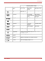
Icons
Icons identify ports, dials, and other parts of your computer. The indicator
panel also uses icons to identify the components it is providing information
on.
Keys
The keyboard keys are used in the text to describe many computer
operations. A distinctive typeface identifies the key top symbols as they
appear on the keyboard. For example, ENTER identifies the ENTER key.
Key operation
Some operations require you to simultaneously use two or more keys. We
identify such operations by the key top symbols separated by a plus sign (+).
For example, CTRL + C means you must hold down CTRL and at the same
time press C. If three keys are used, hold down the first two and at the same
time press the third.
ABC
When procedures require an action such as
clicking an icon or entering text, the icon's name
or the text you are to type in is represented in the
typeface you see to the left.
Display
S
ABC
Names of windows or icons or text generated by
the computer that appear on its display screen
are presented in the type face you see to the left.
Messages
Messages are used in this manual to bring important information to your
attention. Each type of message is identified as shown below.
Pay attention! A caution informs you that improper use of equipment or
failure to follow instructions may cause data loss or damage your
equipment.
Please read. A note is a hint or advice that helps you make best use of
your equipment.
User’s Manual
xxiv
Qosmio G40
Indicates a potentially hazardous situation, which could result in death or
serious injury, if you do not follow instructions.
Terminology
This term is defined in this document as follows:
Start
The word "Start" refers to the "
Microsoft®
User’s Manual
Windows
" button in
VistaTM.
xxv
General Precautions
TOSHIBA computers are designed to optimize safety, minimize strain and
withstand the rigors of portability. However, certain precautions should be
observed to further reduce the risk of personal injury or damage to the
computer.
Be certain to read the general precautions below and to note the cautions
included in the text of the manual.
Creating a computer-friendly environment
Place the computer on a flat surface that is large enough for the computer
and any other items you are using, such as a printer.
Leave enough space around the computer and other equipment to provide
adequate ventilation. Otherwise, they may overheat.
To keep your computer in prime operating condition, protect your work area
from:
■ Dust, moisture, and direct sunlight.
■ Equipment that generates a strong electromagnetic field, such as
stereo speakers (other than speakers that are connected to the
computer) or speakerphones.
■ Rapid changes in temperature or humidity and sources of temperature
change such as air conditioner vents or heaters.
■ Extreme heat, cold, or humidity.
■ Liquids and corrosive chemicals.
Stress injury
Carefully read the Instruction Manual for Safety and Comfort. It contains
information on the prevention of stress injuries to your hands and wrists
that can be caused by extensive keyboard use. Instruction Manual for
Safety and Comfort also includes information on work space design,
posture and lighting that can help reduce physical stress.
User’s Manual
xxvi
Qosmio G40
Heat injury
■ Avoid prolonged physical contact with the computer. If the computer is
used for long periods, its surface can become very warm. While the
temperature will not feel hot to the touch, if you maintain physical
contact with the computer for a long time, for example if you rest the
computer on your lap or if you keep your hands on the palm rest, your
skin might suffer a low-heat injury.
■ If the computer has been used for a long time, avoid direct contact with
the metal plate supporting the various interface ports as this can
become hot.
■ The surface of the AC adaptor can become hot when in use but this
condition does not indicate a malfunction. If you need to transport the
AC adaptor, you should disconnect it and let it cool before moving it.
■ Do not lay the AC adaptor on a material that is sensitive to heat as the
material could become damaged.
Pressure or impact damage
Do not apply heavy pressure to the computer or subject it to any form of
strong impact as this can damage the computer's components or otherwise
cause it to malfunction.
PC Card overheating
Some PC Cards can become hot during prolonged use which may result in
errors or instability in the operation of the device in question. In addition,
you should also be careful when you remove a PC Card that has been
used for a long time.
Mobile phones
Please be aware that the use of mobile phones can interfere with the audio
system. The operation of the computer will not be impaired in any way, but
it is recommended that a minimum distance of 30cm is maintained between
the computer and a mobile phone that is in use.
Instruction Manual for Safety and Comfort
All important information on the safe and proper use of this computer is
described in the enclosed Instruction Manual for Safety and Comfort. Be
sure to read it before using the computer.
User’s Manual
xxvii
Qosmio G40
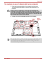
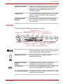
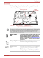
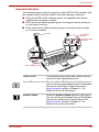
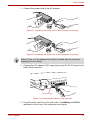
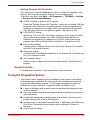
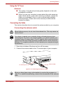
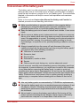
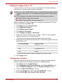
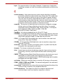
The cautions on use of a Qosmio G40 series computer
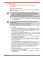
1. Clean any dust accumulated on the computer's cooling vents.
The cooling vents are located on the back and underside of the
computer.
When you use your computer in a dusty area, dirt and debris may
accumulate on the cooling vents at the under side of your unit. If this
occurs, the accumulated dust can cause insufficient heat dissipation which
may result in the computer shutting down during use. Carefully clean the
dust from the vents using a vacuum cleaner.
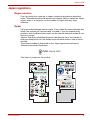
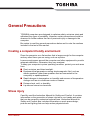
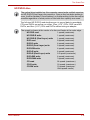
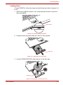
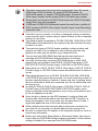
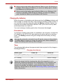
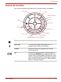
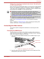
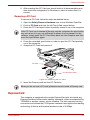
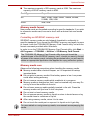
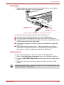
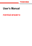
2. Cooling vents on the underside and back of the computer.
Cooling vents
Cooling vents
Speaker
(subwoofer)
Cooling vents
The above illustration is of the subwoofer equipped model. Models without
the subwoofer have cooling vents in the subwoofer location pictured
above. Models with the subwoofer do not have cooling vents in the
subwoofer location pictured above.
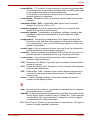
User’s Manual
xxviii
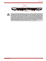
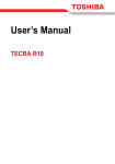
Qosmio G40
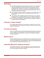
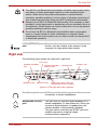
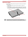
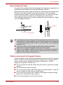
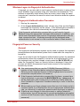
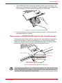
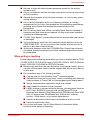
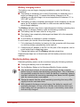
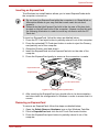
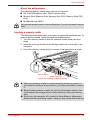
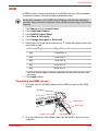
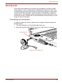
Cooling vents
Cooling vents
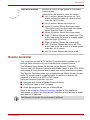
To prevent possible overheating of the CPU, make sure the cooling fan's
air intake is not blocked. The fan draws in air by creating a vacuum. If the
fan is blocked, it could cause the CPU to run at a lower performance level
or cause the computer to shut down. Loose items such as notebook and
tissue paper, plastic wrappers, or other similar materials can block the air
intake, preventing air from reaching the CPU. Do not use the computer on
surfaces with objects that can be drawn in by the cooling fan.
User’s Manual
xxix
Chapter 1
Introduction
This chapter provides an equipment checklist, and it identifies the
computer’s features, options and accessories.
Some of the features described in this manual may not function properly if
you use an operating system that was not pre-installed by TOSHIBA.
Equipment checklist
Carefully unpack your computer, taking care to save the box and packaging
materials for future use.
Hardware
Check to make sure you have all the following items:
■ Qosmio G40 Portable Personal Computer
■ AC adaptor and power cord (2-pin plug or 3-pin plug)
■ Battery pack (Is pre-installed in some computer)
■ Modular cable (Is included with some models)
■ VIDEO-IN cable
■ Remote Controller
■ Infrared transmitter cable
■ Two AA manganese batteries (for Remote Controller)
User’s Manual
1-1
Introduction
Documentation
■ Qosmio G40 Portable Personal Computer User’s Manual
(User’s Manual)
■ Qosmio HD DVD Guide
■ Instruction Manual for Safety and Comfort
■ End User License Agreement
If any of the items are missing or damaged, contact your dealer
immediately.
Software
The following Windows® operating system and utility software are preinstalled.
■ Microsoft® Windows VistaTM
■ TOSHIBA Value Added Package
■ Ulead DVD MovieFactory®
■ Fingerprint Utility
■ Windows Mobility Center
■ TOSHIBA Disc Creator
■ TOSHIBA Recovery Disc Creator
■ TOSHIBA ConfigFree
■ TOSHIBA Assist
■ TOSHIBA SD Memory Utilities
■ CD/DVD Drive Acoustic Silencer
■ TOSHIBA Password Utility
■ TOSHIBA HD DVD PLAYER
■ Online Manual
■ Qosmio G40 User’s Manual (This manual)
■ Discs
■ Windows Anytime Upgrade DVD (Is included with some models)
Please refer to the included Qosmio HD DVD Guide for more information
on using the TOSHIBA HD DVD PLAYER.
User’s Manual
1-2
Introduction
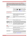
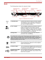
Hardware
This section describes the hardware of your computer.
The actual specifications may vary depending on the model you
purchased.
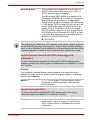
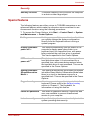
Processor
Built-in
The computer is equipped with one of the
following Intel® processor.
■ Intel® CoreTM 2 Duo Processor, which
incorporates 2MB Level-2 cache memory and
supports Enhanced Intel® SpeedStep®
Technology.
■ Intel® CoreTM 2 Duo Processor, which
incorporates 4MB Level-2 cache memory and
supports Enhanced Intel® SpeedStep®
Technology.
Some models in this series use Intel® Centrino® Duo processor technology
which is based on three separate components, the Intel® CoreTM 2 Duo
processor, Intel® PRO/Wireless network connection and the Mobile Intel®
965 Express Chipset family.
Legal Footnote (CPU)*1
For more information on the CPU, please refer to the Legal Footnotes
section in Chapter 11 or Click the *1 above.
Memory
Slots
User’s Manual
512, 1,024 or 2,048MB memory modules can be
installed in the computer's two memory slots for a
maximum of 4,096MB system memory.
This computer can be equipped with memory
modules of a maximum size of 4,096MB. The
actual amount of useable system memory will be
less than the installed memory modules.
1-3
Introduction
Video RAM
The amount of Video RAM available is
dependent on the computer's system memory.
Start -> Control Panel -> Appearance and
Personalization -> Personalization -> Display
Settings.
The amount of Video RAM can be verified by
clicking the Advanced Settings... button in the
Display Settings window.
Legal Footnote (Memory (Main System))*2
For more information regarding Memory (Main System), please refer to the
Legal Footnotes section in Chapter 11 or click the *2 above.
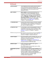
Power
Battery pack
The computer is powered by one rechargeable
lithium-ion battery pack.
Legal Footnote (Battery Life)*3
For more information regarding Battery Life, please refer to the Legal
Footnotes section in Chapter 11 or click the *3 above.
User’s Manual
RTC battery
The internal RTC battery backs up the Real Time
Clock and calendar.
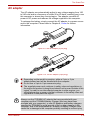
AC adaptor
The AC adaptor provides power to the system
and recharges the batteries when they are low. It
comes with a detachable power cord which will
either have a 2-pin or 3-pin plug enclosure.
As the AC adaptor is universal, it can receive a
range of AC voltages from 100 to 240 volts,
however you should note that the output current
varies among different models. Using the wrong
adaptor can damage your computer. Refer to the
AC adaptor section in Chapter 2, The Grand
Tour.
1-4
Introduction
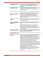
Disks
Hard disk drive
The following 6 types of hard disk drives can be
installed in this computer. The capacity of each
hard disk drive model is different.
■ 80.0 billion bytes (74.53 GB)
■ 100.0 billion bytes (93.16 GB)
■ 120.0 billion bytes (111.79 GB)
■ 160.0 billion bytes (149.05 GB)
■ 200.0 billion bytes (186.32 GB)
■ 250.0 billion bytes (232.90 GB)
Two computer models are available, a model
with a single hard disk drive and a model with two
hard disk drives.
Please note that part of the hard disk drive's
overall capacity is reserved as administration
space.
Legal Footnote (Hard Disk Drive (HDD) Capacity)*4
For more information regarding Hard Disk Drive (HDD) Capacity, please
refer to the Legal Footnotes section in Chapter 11 or click the *4 above.
User’s Manual
1-5
Introduction
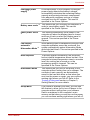
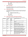
Optical disc drive
HD DVD-ROM drive
User’s Manual
Some models are equipped with a full-size HD
DVD-ROM drive module that lets you run CD's or
DVD's without using an adaptor. The drive reads
DVD-ROM's at a maximum 8x speed and CDROM's at a maximum 24x speed, and HD DVD's
at a maximum 1x speed and writes CD-R's at up
to 16x speed, CD-RW's at up to 10x speed, DVDR's and DVD+R's at up to 4x speed, DVD-RW's
and DVD+RW's at up to 4x speed, DVD-R (Dual
layer) at up to 2x speed, DVD+R (Double Layer)
at up to 2.4x speed and DVD-RAM at up to 3x
speed, and supports the following formats:
■ CD-R
■ CD-RW
■ DVD-ROM
■ DVD-Video
■ CD-DA
■ CD-Text
■ Photo CD™ (single/multi-session)
■ CD-ROM Mode 1, Mode 2
■ CD-ROM XA Mode 2 (Form1, Form2)
■ Enhanced CD (CD-EXTRA)
■ Addressing Method 2
■ DVD-R
■ DVD-R (Dual Layer)
■ DVD-RW
■ DVD+R
■ DVD+R (Double Layer)
■ DVD+RW
■ DVD-RAM
■ HD DVD-ROM
1-6
Introduction
HD DVD-R drive
Some models are equipped with a full-size HD
DVD-R drive module that lets you run CD's or
DVD's without using an adaptor.
The drive reads DVD-ROM's at a maximum 8x
speed and CD-ROM's at a maximum 24x speed,
and HD DVD's at a maximum 1x speed and
writes CD-R's at up to 16x speed, CD-RW's at up
to 10x speed, DVD-R's and DVD+R's at up to 4x
speed, DVD-RW's and DVD+RW's at up to 4x
speed, DVD-R (Dual layer) at up to 2x speed,
DVD+R (Double Layer) at up to 2.4x speed and
DVD-RAM at up to 3x speed, HD DVD-R at up to
1x speed, and supports the following formats in
addition to HD DVD-ROM drive:
■ HD DVD-R
The optical drive installed on this computer cannot write multiple sessions
on HD DVD-R Dual Layer disc sessions. Once a disc has been written to
once, it will be finalized. Once finalized, no further writing to the disc will be
possible regardless of what portion of the total disc capacity was used.
Legal Footnote (General HD DVD technology and
playback)*5
For more information regarding the General HD DVD technology and
playback, please refer to the Legal Footnotes section in Chapter 11 or click
the *5 above.
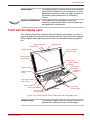
Display
The computer's internal display panel supports high-resolution video
graphics and can be set to a wide range of viewing angles for maximum
comfort and readability.
Built-in
17" TFT LCD screen, 32 million colors, with a
resolution of 1920 horizontal x 1200 vertical
pixels WUXGA.
Legal Footnote (LCD)*6
For more information regarding the LCD, please refer to the Legal
Footnotes section in Chapter 11 or click the *6 above.
Graphics controller
User’s Manual
Graphics controller maximizes display
performance. Refer to Display Controller and
Video modes section in Appendix B for more
information.
1-7
Introduction
Legal Footnote (Graphics Processor Unit ("GPU"))*7
For more information regarding the Graphics Processor Unit ("GPU"),
please refer to the Legal Footnotes section in Chapter 11 or click the *7
above.
Keyboard
Built-in
The internal keyboard provides the embedded
numeric overlay keys, dedicated cursor control
overlay keys,
and
Keys. The keyboard
is compatible with the IBM® enhanced keyboard.
Refer to Chapter 5, The Keyboard, for details.
Pointing Device
Built-in Touch Pad
The integrated Touch Pad and control buttons in
the palm rest allow control of the on-screen
pointer and support functions such as the
scrolling of windows.
Qosmio AV
Controller
This button allows you to operate the Media
Center.
Ports
External monitor
The analog VGA port provides support for VESA
DDC2B compatible functions.
Universal Serial Bus
(USB 2.0)
The computer supports multiple Universal Serial
Bus ports that comply with the USB 2.0 standard.
i.LINK™ (IEEE1394)
This port allows high-speed data transfer to take
place between the computer and external
devices such as digital video cameras.
Slots
User’s Manual
PC Card
The internal PC Card slot accommodates a
single Type II (5mm) card.
ExpressCard
The internal ExpressCard slot is a Universal slot.
This slot supports ExpressCard/54 and
ExpressCard/34 modules.
Bridge media
This slot lets you insert SD/SDHC memory card,
miniSD/microSD Card, Memory Stick (PRO/PRO
Duo), xD picture card and MultiMediaCard. Refer
to Chapter 9, Optional Devices.
1-8
Introduction
Multimedia
User’s Manual
Sound system
The integrated sound system provides support
for the computer's internal speakers and
microphone, as allowing an external microphone
and headphones to be connected via the
appropriate jacks.
Web Camera
Web Camera is a device that allows you to
record video or take photographs with your
computer. You can use it for video chatting or
video conferences using a communication tool
such as Windows Live Messenger. Camera
Assistant Software will help you to add various
video effects to your video or photograph.
Please refer to the Web Camera section in
Chapter 4, Operating Basics.
TV antenna port
Connect the antenna cable to this port to watch
TV programs on your computer or record them.
The dimensions and shape of the TV antenna
port vary for different regions.
S-Video-in Port
A camcorder or other recording device can be
connected to this port via the S-Video-in cable
(optional) for importing video data. Refer to the
S-Video-in section in Chapter 9, Optional
Devices.
S-Video out port
This S-Video out port lets you transfer NTSC or
PAL data to external devices. Refer to the TV
section in Chapter 9, Optional Devices.
VIDEO-IN port
With the bundled VIDEO-IN cable, the CATV or
satellite set top boxes can be connected to the
computer to view the channels.
Please refer to Chapter 8, Connecting the
VIDEO-IN port for details on how to connect the
computer with the VIDEO-IN cable.
HDMI out port
HDMI out port can connect with Type A
connector HDMI cable.
One HDMI cable can send and receive video,
audio and control signals.
Headphone (S/PDIF)
jack
This jack lets you connect digital speakers or a
stereo headphone (16 ohm minimum). When you
connect a digital speaker or headphones, the
internal speaker is automatically disabled.
This jack can be used also as S/PDIF jack and
enables connection of optical digital
correspondence apparatus.
1-9
Introduction
Headphone jack
A 3.5mm mini headphone jack enables
connection of stereo headphones or powered
speakers.
Microphone jack
A 3.5mm mini microphone jack enables
connection of a three-conductor microphone for
monaural input.
Line-in jack
A standard 3.5 mm mini line-in jack enables
connection of a stereo device for audio input.
Built-in TV Tuner
Built-in TV Tuner enables watching and
recording TV programs. Some models are
capable of simultaneously recording 2 different
television programs.
Infrared receiver
window
This is a sensor window that receives signals
from the Remote Controller which is provided
with your computer.
Infrared transmitter
cable port
Connect the Infrared transmitter cable to this
port.
Connecting the set top box or other external
device to the computer using the infrared
transmitter cable allows the external device to be
operated using the computer and specialized
remote control.
Remote Controller
Use this device to navigate when watching TV or
playing CDs/DVDs/HD DVDs.
Communications
Modem
User’s Manual
Some models are equipped with the integrated
modem. The integrated modem provides
capability for data and fax communications that
support the V.90 (V.92) standards and includes a
modem jack for connection to the telephone line.
Please note that both the V.90 and V.92
standards are only supported in the USA,
Canada, United Kingdom, France, Germany and
Australia - only the V.90 standard is supported in
other regions. You should also be aware that the
speed of data and fax transfer will depend on the
analog telephone line conditions.
The integrated model is only installed as a
standard device in some markets. Please refer to
the V.90 section in Appendix E for more
information.
1-10
Introduction
LAN
The computer has built-in support for Ethernet
LAN (10 megabits per second, 10BASE-T), Fast
Ethernet LAN (100 megabits per second,
100BASE-TX) and Gigabit Ethernet LAN (1000
megabits per second, 1000BASE-T).
It is pre-installed as a standard device in some
markets.
Bluetooth
Some computers in this series offer Bluetooth
wireless communication functionality which
eliminates the need for cables between
electronic devices such as computers and
printers. When implemented, Bluetooth provides
a fast, reliable and secure means to achieve
wireless communication in a small space.
Wireless LAN
Some computers in this series are equipped with
a Wireless LAN card that is compatible with other
LAN systems based on Direct Sequence Spread
Spectrum/Orthogonal Frequency Division
Multiplexing radio technology that complies with
the IEEE 802.11 Standard (Revision A, B, G or N
Draft Ver. 1.0).
■ The transmission speed over the wireless LAN and the distance over
which wireless LAN can reach may vary depending on surrounding
electromagnetic environment, obstacles, access point design and
configuration, and client design and software/hardware configurations.
The Transmit Rate (at X Mbit/s) is the theoretical maximum speed
under the IEEE802.11 (a/b/g) standard. The actual transmission speed
will be lower than the theoretical maximum speed.
■ The Wake-up on Wireless LAN function is effective only when it is
connected with an Access Point. This function becomes invalid when
the connection is broken.
Legal Footnote (Wireless LAN)*8
For more information regarding Wireless LAN, please refer to the Legal
Footnotes section in Chapter 11 or click the *8 above.
Wireless
communication
switch
User’s Manual
This switch turns the Wireless LAN and Bluetooth
functions on and off. Please note that all models
are provided with a Wireless communication switch
and some models are equipped with both Wireless
LAN and Bluetooth functionality.
1-11
Introduction
Security
Security lock slot
Connects a security lock to anchor the computer
to a desk or other large object.
Special features
The following features are either unique to TOSHIBA computers or are
advanced features which make the computer more convenient to use.
Access each function using the following procedures.
*1 To access the Power Options, click Start -> Control Panel -> System
and Maintenance -> Power Options.
User’s Manual
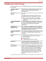
Hot keys
Hot keys are specific key combinations that let
you quickly change the system configuration
directly from the keyboard without running a
system program.
Display automatic
power off *1
This feature automatically cuts off power to the
computer's display panel when there is no
keyboard input for a specified time, with power
being restored the next time a key is pressed.
This can be specified in the Power Options.
HDD automatic
power off *1
This feature automatically cuts off power to the
hard disk drive when it is not accessed for a
specified time, with power being restored when
the hard disk drive is next accessed. This can be
specified in the Power Options.
System automatic
Sleep/Hibernation
Mode *1
This feature automatically shuts down the system
into either Sleep Mode or Hibernation Mode when
there is no input or hardware access for a
specified time. This can be specified in the Power
Options.
Keypad overlay
A ten-key numeric keypad is integrated into the
keyboard. Please refer to the Keypad overlay
section in Chapter 5, The Keyboard, for
information on using this feature.
Power on password
Two levels of password security, supervisor and
user, are available to prevent unauthorized
access to your computer.
Instant security
A specific hot key function automatically locks the
system providing data security.
1-12
Introduction
Intelligent power
supply *1
A microprocessor in the computer's intelligent
power supply detects the battery's charge,
automatically calculates the remaining battery
capacity and protects electronic components
from abnormal conditions such as a voltage
overload from the AC adaptor. This can be
specified in the Power Options.
Battery save mode *1 This feature lets you configure the computer in
order to save battery power. This can be
specified in the Power Options.
Panel power on/off
*1
User’s Manual
This feature automatically turns power to the
computer off when the display panel is closed,
and turns it back on when the display panel is
opened. This can be specified in the Power
Options.
Low battery
automatic
Hibernation Mode *1
When battery power is exhausted to the point that
computer operation cannot be continued, the
system automatically enters Hibernation Mode
and shuts itself down. This can be specified in the
Power Options.
Heat dispersal *1
To protect against overheating, the processor
has an internal temperature sensor so that, if the
computer's internal temperature rises to a certain
level, the cooling fan is turned on or the
processing speed is lowered. This can be
specified in the Power Options.
Hibernation Mode
This feature lets you turn off the power to the
computer without exiting from your software. The
contents of main memory are automatically
saved to the hard disk drive so that when you
next turn the power on again, you can continue
working right where you left off. Refer to the
Turning off the power section in Chapter 3,
Getting Started, for more details.
Sleep Mode
If you have to interrupt your work, you can use
this feature to allow you to turn off power to the
computer without exiting from your software.
Data is maintained in the computer's main
memory so that when you next turn on the power,
you can continue working right where you left off.
1-13
Introduction
TOSHIBA Value Added Package
This section describes the TOSHIBA Component features pre-installed on
the computer.
User’s Manual
TOSHIBA Power
Saver
TOSHIBA Power Saver provides you with the
features of more various power supply
managements.
TOSHIBA Button
Support
This utility controls the following computer panel
functions.
The applications associated with each of the
following panels can be assigned by the user.
■ Panels: Assign applications to the REC,
Brightness, Illumination On/Off, DOLBY, TVout panels.
TOSHIBA Zooming
Utility
This utility allows you to enlarge or reduce the
icon size on the Windows Desktop, or the zoom
factor associated with specific supported
applications.
TOSHIBA PC
Diagnostic Tool
The TOSHIBA PC Diagnostic Tool will display
basic system configuration information and allow
the functionality of some of the computer's builtin hardware devices to be tested.
TOSHIBA Password
Utility
The TOSHIBA Password utility allows you to set
a password in order to restrict access to the
computer.
TOSHIBA Flash
Cards
The TOSHIBA Flash Cards provide a quick way
to modify selected system functions and to
launch applications.
■ Hot key function
■ TOSHIBA utility launcher function
HW Setup
This utility allows you to customize your
hardware settings according to the way you work
with the computer and the peripherals you use.
TOSHIBA
Accessibility
The TOSHIBA Accessibility utility provides
support to movement impaired users when they
need to use the TOSHIBA Hot-key functions. In
use, the utility allows you to make the FN key
'sticky', that is you can press it once, release it,
and they press one of the 'F' keys in order to
access its specific function. When set, the FN
key will remain active until another key is
pressed.
1-14
Introduction
Utilities and Applications
This section describes the pre-installed utilities that come with the
computer and details how to start them. For further information on their
operation, please refer to each utility's online manual, help files or
README.TXT file.
Fingerprint Utility
This product has a fingerprint utility installed for
the purpose of enrolling and recognizing
fingerprints which can then be linked to a
username and password in order to remove the
need to input these details from the keyboard.
Just by swiping an enrolled finger against the
fingerprint sensor, the following functions will be
enabled:
■ Logon to Windows and access a security
enabled homepage through Internet Explorer.
■ Files and folders can be encrypted/decrypted
and third party access to them is prevented.
■ Disable the password-protected screen-saver
when returning from a power-saving mode
such as Sleep Mode.
■ Authentication of the User Password (and, if
applicable, the HDD(Hard Disk Drive)
Password) when booting up the computer
(Power-on Security).
■ Single Sign-on feature
Bluetooth Stack for
Windows by Toshiba
This software enables communication between
the computer and external Bluetooth devices
such as printers and mobile phones.
Bluetooth functions cannot be used in models that do not have a Bluetooth
module installed.
TOSHIBA Assist
TOSHIBA Assist is a graphical user interface that
provides access to specific tools, utilities and
applications that make the use and configuration
of the computer easier.
TOSHIBA ConfigFree TOSHIBA ConfigFree is a suite of utilities that
improve the ease and control of communication
devices and network connections, help in the
identification of communication problems and
allow the creation of profiles if you need to switch
between different locations and communication
networks. To access this utility, click Start -> All
Programs -> TOSHIBA -> Networking ->
ConfigFree.
User’s Manual
1-15
Introduction
TOSHIBA Disc
Creator
You can create CD's and DVD's in a number of
formats including audio CD's that can be played
on a standard CD player, and data CD's/DVD's
which can store copies of the files and folders on
your computer's hard disk drive. This software
can be used on models with either a HD DVDROM drive or a HD DVD-R drive.
To access this utility, click Start -> All Programs
-> TOSHIBA -> CD&DVD Applications -> Disc
Creator.
TOSHIBA DVD-RAM
Utility
TOSHIBA DVD-RAM Utility has the function of
Physical Format and Write-Protect to DVD-RAM.
This utility is contained the setup module of
TOSHIBA Disc Creator. To access this utility,
click Start -> All Programs -> TOSHIBA ->
CD&DVD Applications -> DVD-RAM Utility.
Ulead DVD
MovieFactory for
TOSHIBA
Ulead DVD MovieFactory for TOSHIBA allows
users to instantly create DVD video or slideshow
discs via a user-friendly wizard interface with
specific task oriented features.
TOSHIBA SD
This utility allows you to format an SD memory
Memory Card Format card by the SD standard format.
User’s Manual
Windows Mobility
Center
This section describes the Windows Mobility
Center. Mobility Center is a utility for accessing
several mobile PC settings quickly in one
window. A default maximum of eight tiles are
provided by the operating system, and the
additional two tiles are added to your Mobility
Center.
■ Lock Computer:
This can be used to lock your computer without
turning it off. This has the same function as the
Lock button at the bottom of the right pane in the
start menu.
■ TOSHIBA Assist:
This can be used to open TOSHIBA Assist if it is
already installed in your computer.
TOSHIBA HD DVD
PLAYER
This software is provided for playback of HD
DVD Video.
Please refer to the included Qosmio HD DVD
Guide for more information on using the
TOSHIBA HD DVD PLAYER.
1-16
Introduction
CD/DVD Drive
Acoustic Silencer
The CD/DVD Drive Acoustic Silencer utility
allows you to configure the read speed at which
the optical disc drive will operate. In use you can
select either Normal Mode, which will operate
the drive at its maximum speed for quick data
access, or Quiet Mode, which operates the drive
at single speed for audio CD playback and which
can lessen the operational noise. This utility does
not have any function when using DVD's.
Options
You are able to add a number of options and accessories in order to make
your computer even more powerful and convenient to use. For reference,
the following list details some of the items that are available from your
reseller or TOSHIBA dealer:
User’s Manual
Memory expansion
A 512MB, 1,024MB or 2,048MB memory module
(DDR2-667) can easily be installed in the
computer.
Battery Pack
An additional battery pack can be purchased for
use as either a spare or replacement. Please
refer to Chapter 6, Power for futher information.
Universal AC
Adaptor
If you frequently use your computer at more than
one site, it may be convenient to purchase an
additional AC adaptor to be kept at each site in
order to remove the need to always carry the
adaptor with you.
USB FDD kit
The USB floppy diskette drive accommodates
either a 1.44MB or 720KB floppy diskette through
connection to one of the computer's USB ports.
In use, please be aware that, while you cannot
format 720KB floppy diskettes under Windows
VistaTM, you are able to read and write to
diskettes that have already been formatted.
Battery Charger
The optional battery charger allows you to
charge extra battery packs outside of having to
use the computer.
Bluetooth USB
Adaptor
A Bluetooth adaptor that has a USB connector.
Wireless communications can be carried out with
Bluetooth-compatible equipment by connecting
to the USB port of the computer.
You can buy the module from a TOSHIBA dealer.
1-17
Introduction
User’s Manual
Bluetooth Wireless
Mouse
The Bluetooth Wireless Mouse is a wireless
optical mouse compatible with Bluetooth.
You can buy the Bluetooth Wireless Mouse from
a TOSHIBA dealer.
Bluetooth Wireless
Stereo
The Bluetooth Wireless Stereo is a wireless
stereo headphone set compatible with Bluetooth.
You can buy the Bluetooth Wireless Stereo from
a TOSHIBA dealer.
1-18
Chapter 2
The Grand Tour
This chapter identifies the various components of your computer. Become
familiar with each component before you operate the computer.
Legal Footnote (Non-applicable Icons)*9
For more information regarding Non-applicable Icons, please refer to the
Legal Footnotes section in Chapter 11 or click the *9 above.
Front with the display closed
The following figures show the computer’s front with its display panel in the
closed position.
System indicators
HD DVD-ROM drive or HD DVD-R drive
Display latch
Infrared receiver window
Figure 2-1 Front of the computer with display closed
HD DVD-ROM drive
The computer is configured with a HD DVD-ROM
drive.
HD DVD-R drive
The computer is configured with a HD DVD-R
drive.
The computer is equipped with one of the following optical disc drive.
■ HD DVD-ROM drive
■ HD DVD-R drive
User’s Manual
2-1
The Grand Tour
System indicators
These LED indicators allow you to monitor the
status of various computer functions and are
described in more detail within the System
indicators section.
Display latch
This latch secures the display panel in its closed
position - push the latch in order to open the
display for use.
Infrared receiver
window
This is a sensor window that receives signals
from the remote control which is provided with
your computer.
Left side
The following figure shows the computer's left side.
Security lock slot
Bridge media slot
Universal Serial Bus Wireless communication switch
(USB 2.0) port
i.LINK (IEEE1394) port
ExpressCard slot
PC Card slot
PC Card eject
button
ExpressCard
eject button
Universal Serial Bus
(USB 2.0) port
Figure 2-2 The left side of the computer
User’s Manual
Security lock slot
A security cable can be attached to this slot and
then connected to a desk or other large object in
order to deter theft of the computer.
ExpressCard slot
This slot allows you to install a single
ExpressCard device.
ExpressCard eject
button
This button is used in order to remove an
ExpressCard from within the computer.
PC Card slot
This slot can accommodate a single Type II, 16bit or 32-bit (CardBus) PC Card device.
PC Card eject button
This button is used in order to remove a PC Card
from within the computer.
2-2
The Grand Tour
Keep foreign metal objects, such as screws, staples and paper clips, out of
the ExpressCard slot and PC Card slot. Foreign metal objects can create a
short circuit, which can cause damage and fire, possibly resulting in
serious injury.
Universal Serial Bus
(USB 2.0) ports
Two Universal Serial Bus ports, which comply
with the USB 2.0 standard, are provided on the
left hand side of the computer. The ports with the
icon (
) has USB Sleep and Charge function.
Keep foreign metal objects, such as screws, staples and paper clips, out of
the USB connectors. Foreign metal objects can create a short circuit,
which can cause damage and fire, possibly resulting in serious injury.
Please note that it is not possible to confirm the operation of all functions of
all USB devices that are available. In view of this it may be noted that
some functions associated with a specific device might not operate
properly.
Bridge media slot
This slot lets you insert an SD/SDHC memory
card, miniSD/microSD Card, Memory Stick
(PRO/PRO Duo), xD picture card and
MultiMediaCard. Refer to Chapter 9, Optional
Devices.
Keep foreign metal objects, such as screws, staples and paper clips, out of
the Bridge media slot. Foreign metal objects can create a short circuit,
which can cause damage and fire, possibly resulting in serious injury.
Wireless
communication
switch
User’s Manual
Slide this switch to the right to turn off Wireless
LAN and Bluetooth functions. Slide it to the left to
turn on the functions.
All models are provided with a Wireless
communication switch although only some
models are equipped with both Wireless LAN
and Bluetooth functions.
2-3
The Grand Tour
■ Turn Wi-Fi® and Bluetooth functionalities off when near a person who
may have a cardiac pacemaker implant or other medical electric
device. Radio waves may affect pacemaker or medical device
operation, possibly resulting in serious injury. Follow the instruction of
your medical device when using any Wi-Fi or Bluetooth functionality.
■ Always turn off Wi-Fi or Bluetooth functionality if the computer is near
automatic control equipment or appliances such as automatic doors or
fire detectors. Radio waves can cause malfunction of such equipment,
possibly resulting in serious injury.
■ Do not use the Wi-Fi or Bluetooth functionalities near a microwave
oven or in areas subject to radio interference or magnetic fields.
Interference from a microwave oven or other source can disrupt Wi-Fi
or Bluetooth operation.
i.LINK (IEEE1394)
port
This port allows you to connect an external
device, such as a digital video camera, to the
computer for high-speed data transfer.
Right side
The following figure shows the computer’s right side.
Line-in jack
Headphone (S/PDIF)
jack
Headphone jack
Universal Serial Bus
(USB 2.0) port
Microphone jack
VIDEO-IN port
S-Video-in port
Modem jack (Some models are
equipped with a built-in modem)
Figure 2-3 The right side of the computer
User’s Manual
Headphone jack
A 3.5 mm mini headphone jack enables
connection of stereo headphones.
Headphone (S/PDIF)
jack
This jack lets you connect digital speakers or a
stereo headphone (16 ohm minimum). When you
connect a digital speaker or headphones, the
internal speaker is automatically disabled.
This jack can be used also as S/PDIF jack and
enables connection of optical digital
correspondence apparatus.
2-4
The Grand Tour
Microphone jack
A 3.5 mm mini microphone jack enables
connection of a three-conductor mini jack for
monaural microphone input.
Line-in jack
A standard 3.5 mm mini line-in jack enables
connection of a stereo device for audio input.
Universal Serial Bus
(USB 2.0) port
The Universal Serial Bus port, which complies
with the USB 2.0 standard, is provided on the
right side of the computer.
Modem jack
The modem jack allows you use to attach a
modular cable in order to connect the internal
modem directly to a telephone line.
Some models are equipped with a built-in
modem.
■ Connection to any communication line other than an analog phone line
could cause a computer system failure.
■ Connect the built-in modem only to ordinary analog phone lines.
■ Never connect the built-in modem to a digital line (ISDN).
■ Never connect the built-in modem to the digital connector on a
public telephone or to a digital private branch exchange (PBX).
■ Never connect the built-in modem to a key telephone system for
residences or offices.
■ Never operate your computer on AC power during a thunderstorm. If
you see lightning or hear thunder, immediately turn off the computer.
An electric surge caused by the storm, may result in a system failure,
loss of data or hardware damage.
User’s Manual
VIDEO-IN port
With the bundled VIDEO-IN cable, the CATV or
satellite set top boxes can be connected to the
computer to view the channels.
Please refer to Chapter 8, AV functions for
details on how to connect the computer with the
VIDEO-IN cable.
S-Video-in port
A camcorder or other recording device can be
connected to your computer via the S-Video-in
cable for importing video data. Connect the cable
to this port for this operation. Refer to the SVideo-in section in Chapter 9, Optional Devices.
2-5
The Grand Tour
Back
The following figure shows the computer’s back.
Infrared transmitter
cable ports
TV antenna port
Universal Serial Bus
(USB 2.0) ports
S-Video out port
DC IN 15V jack
LAN active indicator
(orange)
Link indicator
External monitor port
(green)
Cooling vents
HDMI out port
LAN jack
Figure 2-4 The back of the computer
TV antenna port
Connect the antenna cable to this port to watch
TV programs on your computer or record them.
The dimensions and shape of the TV antenna
port vary for different regions.
DC IN 15V jack
The AC adaptor connects to this jack in order to
power the computer and charge its internal
batteries. Please note that you should only use
the model of adaptor supplied with the computer
at the time of purchase - using the wrong adaptor
can cause damage to the computer.
Cooling vents
The computer's cooling vents help keep the
processor from overheating.
Do not block the cooling vents. Keep foreign metal objects, such as
screws, staples and paper clips, out of the cooling vents. Foreign metal
objects can create a short circuit, which can cause damage and fire,
possibly resulting in serious injury.
User’s Manual
Infrared transmitter
cable ports
Connect the infrared transmitter cable to the
infrared transmitter cable port on the computer
and to the set-top box.
S-Video out port
The S-Video out port supports the connection of
an optional S-Video cable to attach the computer
to a television or similar device.
Universal Serial Bus
(USB 2.0) ports
Two Universal Serial Bus ports, which comply
with the USB 2.0 standard, are provided on the
back of the computer.
2-6
The Grand Tour
External monitor
port
This port allows you to connect an external video
display to the computer.
HDMI out port
HDMI out port can connect with Type A
connector HDMI cable.
One HDMI cable can send and receive video,
audio and control signals.
LAN jack
This jack lets you connect to a LAN. The adaptor
has built-in support for Ethernet LAN (10
megabits per second, 10BASE-T), Fast Ethernet
LAN (100 megabits per second, 100BASE-TX)
and Gigabit Ethernet LAN (1000 megabits per
second, 1000BASE-T). The LAN has two
indicators. Refer to Chapter 4, Operating Basics,
for details.
■ Do not connect any cable other than a LAN cable to the LAN jack. It
could cause damage or malfunction.
■ Do not connect the LAN cable to a power supply. It could cause
damage or malfunction.
User’s Manual
Link indicator
(green)
This indicator glows green when the computer is
connected to a LAN and the LAN is functioning
properly.
LAN active
indicator (orange)
This indicator glows orange when data is being
exchanged between the computer and the LAN.
2-7
The Grand Tour
Underside
The following figure shows the underside of the computer. You should
ensure that the display is closed before the computer is turned over to
avoid causing any damage.
Memory module slots
Battery pack
Battery release latch
Speaker
(subwoofer)
Battery safety lock
Figure 2-5 The underside of the computer
The above illustration is of the subwoofer equipped model. Models without
the subwoofer have cooling vents in the subwoofer location pictured
above. Models with the subwoofer do not have cooling vents in the
subwoofer location pictured above.
User’s Manual
Memory module
slots
The memory module slots are located here. The
memory module slots allow for the installation,
replacement and removal of additional memory
modules. Please refer to the Memory expansion
section in Chapter 9, Optional Devices for more
information.
Battery safety lock
Slide this latch into its 'Unlock' position in order to
release the battery pack ready for removal.
Battery release
latch
Slide and hold this latch into its 'Unlock' position
in order to release the battery pack ready for
removal.
For more detailed information on removing the
battery pack please refer to Chapter 6, Power.
2-8
The Grand Tour
Battery pack
The battery pack provides power to the computer
when the AC adaptor is not connected. For more
detailed information on the use and operation of
the battery pack please refer to Chapter 6,
Power.
Speaker (subwoofer)
The subwoofer will reproduce of the low
frequency sounds generated. Some models are
equipped with a subwoofer.
Front with the display open
This section shows the computer with the display panel open. In order to
open the display, simply push the display latch on the front of the computer,
lift the display panel up and position it at a comfortable viewing angle for
you.
Web Camera LED
Web Camera
Microphone
Display screen
Stereo speaker
(tweeter right)
Stereo speaker
(tweeter left)
Display hinge
Stereo speaker
(Right)
Qosmio AV
Controller
Display hinge
Fingerprint
Sensor
Stereo speaker
(Left)
LCD Sensor switch
(Not shown)
Power button
Volume control dial
Touch Pad
Touch Pad
control buttons
Front operation panel
(eleven panels)
Figure 2-6 The front of the Touch Pad model with the display open
Display hinge
User’s Manual
The display hinges allow the display panel to be
position at a variety of easy-to-view angles.
2-9
The Grand Tour
Stereo speakers
The speakers will reproduce all of the sounds
generated through the installed software,
together with any alarms, such as that
accompanying a low battery condition, that are
generated by the system.
Keep foreign objects out of the speakers. Never allow metal objects, such
as screws, staples and paper clips, to enter the computer or keyboard.
Foreign metal objects can create a short circuit, which can cause computer
damage and fire, possibly resulting in serious injury.
User’s Manual
Speakers (tweeter)
The tweeter will reproduce of the high-frequency
sounds generated.
Display screen
The internal screen displays high-contrast text
and graphics images up to the maximum
resolution supported by the model in question.
For example, an WUXGA compatible model will
support resolutions between 800x600 and
1920x1200 pixels.
Please be aware that, when the computer is
operating on the AC adaptor, the image
displayed on the internal screen will be
somewhat brighter than when it operates on
battery power. This difference in brightness
levels is intended to save power when operating
on batteries. For more information on the
computer's display, please refer to the Display
Controller and Video modes section in Appendix
B.
Front operation
panel (eleven
panels)
Eleven panels are available for use:
TV, CD/DVD, Play/Pause, Stop, Previous, Next,
Record, Brightness, Illumination On/Off, DOLBY,
TV-out.
These panels allow you to manage Audio/Video,
run applications and access utilities.
Refer to Chapter 8, AV functions for details.
Power button
Press this button to turn the computer's power on
and off. The Power button will glow blue when
the computer's power is on.
Touch Pad
The Touch Pad mouse control device located in
the center of the palm rest is used to control the
movement of the on-screen pointer. For more
information, please refer to the Using the Touch
Pad section in Chapter 4, Operating Basics.
2-10
The Grand Tour
User’s Manual
Touch Pad control
buttons
The control buttons located below the Touch Pad
allow you to select menu items or manipulate text
and graphics as designated by the on-screen
pointer.
Fingerprint Sensor
Just by swiping a valid and enrolled finger against
the fingerprint sensor, the following functions will be
enabled:
■ Logon to Windows and access a security
enabled homepage through Internet Explorer.
■ Files and folders can be encrypted/decrypted
and third party access to them prevented.
■ Disable the password-protected screen-saver
when returning from a power-saving mode
such as Sleep Mode.
■ Power-on security and single sign-on
facilities.
Web Camera
Web Camera is a device that allows you to
record video or take photographs with your
computer. You can use it for video chatting or
video conferences using a communication tool
such as Windows Live Messenger. Camera
Assistant Software will help you to add various
video effects to your video or photograph.
Enables the transmission of video and use of
video chat via the internet using specialized
applications.
The effective pixel count for this web camera is
1.92 million.
Please refer to the Web Camera section in
Chapter 4, Operating Basics.
Web Camera LED
The Web Camera LED lights up when the Web
Camera is operating.
Qosmio AV
Controller
This button allows you to operate the Media
Center.
Please refer to the Qosmio AV Controller section
in Chapter 8, AV functions for more information.
2-11
The Grand Tour
LCD Sensor switch
This switch senses when the display panel is
either closed or opened and activates the Panel
Power Off/On feature as appropriate. For
example, when you close the display panel the
computer enters Hibernation Mode and shuts
itself down and then, when you next open the
display, the computer will automatically start up
and return you to the application you were
previously working on.
You can specify within the Power Options. To
access it, click Start -> Control Panel ->
System and Maintenance -> Power Options.
Do not put any magnetic objects close to this switch as they may cause the
computer to automatically enter Hibernation Mode and shut down even if
the Panel Power Off feature is disabled.
Volume control dial
Use this dial to adjust the volume of the internal
stereo speakers and optional external stereo
headphones (if connected).
Turn the dial clockwise to increase the volume
and turn it counter-clockwise to decrease the
volume.
Microphone
A built-in microphone allows you to import and
record sounds for your applications - please refer
to the Sound system section in Chapter 4,
Operating Basics for more information.
System indicators
The LED system indicators for specific computer operations glow when
those operations are in progress.
Figure 2-7 System indicators
DC IN
User’s Manual
The DC IN indicator normally glows blue when
power is being correctly supplied from the AC
power adaptor. However, If the output voltage
from the adaptor is abnormal, or if the computer's
power supply malfunctions, this indicator will
flash orange.
2-12
The Grand Tour
User’s Manual
Power
The Power indicator normally glows blue when
the computer is turned on. However, if you turn
the computer off into Sleep Mode, this indicator
will flash orange - approximately one second on,
two seconds off - both while the system is
shutting down and while it remains turned off.
Battery
The Battery indicator shows the condition of the
battery's charge - blue indicates the battery is
fully charged, orange indicates the battery is
charging, and flashing orange indicates a low
battery condition. Please refer to Chapter 6,
Power for more information on this feature.
Hard Disk Drive
The Hard Disk Drive indicator glows blue
whenever the computer is accessing the built-in
hard disk drive.
Optical Disc Drive
The Optical Disc Drive indicator glows blue
when the computer is accessing a disc in the
optical disc drive.
Bridge media slot
The Bridge media slot indicator glows blue
when the computer is accessing the Bridge
media slot.
Wireless
communication
The Wireless communication indicator glows
orange when the Bluetooth and wireless LAN
functions are turned on.
All models are provided with a Wireless
Communication switch although only some
models are equipped with both Wireless LAN
and Bluetooth functions.
2-13
The Grand Tour
Keyboard indicators
The following figures show the positions of the CAPS LOCK indicator and
the keypad overlay indicators which show the following conditions:
■ When the CAPS LOCK indicator glows, the keyboard will produce
capitals when any letter is typed.
■ When the Arrow Mode indicator glows, the keypad overlay allows you
to use cursor functions.
■ When the Numeric Mode indicator glows, the keypad overlay allows
you to enter numbers.
Arrow Mode
indicator
Numeric Mode
indicator
CAPS LOCK indicator
Figure 2-8 Keypad indicators
User’s Manual
CAPS LOCK
This indicator glows green when letter keys are
locked into their uppercase format.
Arrow Mode
When the Arrow Mode indicator lights green,
you can use the gray labeled keys on the keypad
overlay as cursor keys. Please refer to the
Keypad overlay section in Chapter 5, The
Keyboard for more information.
Numeric Mode
When the Numeric Mode indicator lights green,
you can use the gray labeled keys on the keypad
overlay for number entry. Please refer to the
Keypad overlay section in Chapter 5, The
Keyboard for more information.
2-14
The Grand Tour
Optical disc drives
One of the following optical disc drives is provided in the computer: HD
DVD-ROM and HD DVD-R drives. This optical drive uses an ATAPI
interface controller for CD and DVD operation and has an indicator at its
front which will glows to indicate that it is in use.
For further information on loading and unloading discs, please refer to the
Using HD DVD-ROM drive and HD DVD-R drives section in Chapter 4,
Operating Basics.
Region codes for DVD drives and media
HD DVD-ROM drive, HD DVD-R drives and their associated media are
manufactured according to the specifications of six marketing regions.
When you purchase DVD Video media you should ensure that it matches
the specification of your drive, otherwise it will not play properly.
Code
Region
1
Canada, United States
2
Japan, Europe, South Africa, Middle East
3
South East Asia, East Asia
4
Australia, New Zealand, Pacific Islands, Central
America, South America, Caribbean
5
Russia, Indian Subcontinent, Africa, North Korea,
Mongolia
6
China
Writable discs
This section describes the types of writable CD, DVD and HD DVD media
available, and should be used in conjunction with the specification of your
computer/optical drive in order to understand the type of discs that can be
written. Please refer to Chapter 4, Operating Basics for further information.
CDs
■ CD-R media can only be written to once - the recorded data cannot
subsequently be erased or changed.
■ CD-RW media, including multi-speed CD-RW discs, high-speed CDRW discs and ultra-speed CD-RW discs, can be recorded to more than
once.
User’s Manual
2-15
The Grand Tour
DVDs
■ DVD-R, DVD+R, DVD-R (Dual Layer) and DVD+R (Double Layer)
media discs can only be written to once - the recorded data cannot
subsequently be erased or changed.
■ DVD-RW, DVD+RW and DVD-RAM media can be recorded to more
than once.
HD DVDs
■ HD DVD-R and HD DVD-R (Dual Layer) media discs can only be
written to once - the recorded data cannot subsequently be erased or
changed.
Formats
The drives support the following formats:
■
■
■
■
■
■
■
CD-ROM
DVD-ROM
DVD-R
DVD-R (Dual Layer)
DVD-RW
DVD+R
DVD+R (Double
Layer)
■ DVD+RW
■ DVD-RAM
■ DVD-Video
■
■
■
■
■
CD-R
■
CD-RW
■
CD-DA
CD-Text
■
CD-ROM XA Mode 2
(Form1, Form2)
■ CD-ROM Mode 1,
■
Mode 2
■ Photo CD™
■
(single/multi-session)
■ Enhanced CD (CDEXTRA)
Addressing Method 2
HD DVD-ROM
(Single-sided SingleLayer)
HD DVD-ROM
(Single-sided DualLayer)
HD DVD (Twin format
disc)
HD DVD-Video
Some types and formats of DVD-R (Dual Layer) and DVD+R (Double
Layer) discs may be unreadable.
User’s Manual
2-16
The Grand Tour
HD DVD-ROM drive
The full-size HD DVD-ROM module allows you to record data to recordable
CD's and DVD's as well as run either 12cm (4.72") CD's, DVD's and HD
DVD's, and 8cm (3.15") CD's and DVD's without using an adaptor.
The speed is slower at the center of a disc and faster at the outer edge.
HD DVD read
1 speed (maximum)
DVD read
8 speed (maximum)
DVD-R write
4 speed (maximum)
DVD-R (Dual Layer) write
2 speed (maximum)
DVD-RW write
4 speed (maximum)
DVD+R write
4 speed (maximum)
DVD+R (Double Layer) write
2.4 speed (maximum)
DVD+RW write
4 speed (maximum)
DVD-RAM write
3 speed (maximum)
CD read
24 speed (maximum)
CD-R write
16 speed (maximum)
CD-RW write
10 speed (maximum,
Ultra-speed media)
User’s Manual
2-17
The Grand Tour
HD DVD-R drive
The optical drive installed on this computer cannot write multiple sessions
on HD DVD-R Dual Layer disc sessions. Once a disc has been written to
once, it will be finalized. Once finalized, no further writing to the disc will be
possible regardless of what portion of the total disc capacity was used.
The full-size HD DVD-R module allows you to record data to recordable
CD's and DVD's as well as run either 12cm (4.72") CD's, DVD's and HD
DVD's, and 8cm (3.15") CD's and DVD's without using an adaptor.
The speed is slower at the center of a disc and faster at the outer edge.
HD DVD read
1 speed (maximum)
HD DVD-R write
1 speed (maximum)
HD DVD-R (Dual Layer) write
1 speed (maximum)
DVD read
8 speed (maximum)
DVD-R write
4 speed (maximum)
DVD-R (Dual Layer) write
2 speed (maximum)
DVD-RW write
4 speed (maximum)
DVD+R write
4 speed (maximum)
DVD+R (Dual Layer) write
2.4 speed (maximum)
DVD+RW write
4 speed (maximum)
DVD-RAM write
3 speed (maximum)
CD read
24 speed (maximum)
CD-R write
16 speed (maximum)
CD-RW write
10 speed (maximum,
Ultra-speed media)
User’s Manual
2-18
The Grand Tour
AC adaptor
The AC adaptor can automatically adjust to any voltage ranging from 100
to 240 volts and to a frequency of either 50 or 60 hertz, enabling you to use
this computer in almost any country/region. The adaptor converts AC
power to DC power and reduces the voltage supplied to this computer.
To recharge the battery, simply connect the AC adaptor to a power source
and to the computer. Please refer to Chapter 6, Power for further
information.
Figure 2-9 The AC adaptor (2-pin plug)
Figure 2-10 The AC adaptor (3-pin plug)
■ Depending on the model in question, either a 2-pin or 3-pin
adaptor/power lead will be bundled with the computer.
■ Do not use a 3-pin to 2-pin conversion plug.
■ The supplied power cord conforms to safety rules and regulations in
the region the product is bought and should not be used outside of this
region. In order to use the adaptor/computer in other regions, you
should please buy a power cord that conforms to the safety rules and
regulations in that particular region.
Always use the TOSHIBA AC adaptor that was provided with your
computer and the TOSHIBA Battery Charger (that may have been
provided with your computer), or use AC adaptors and battery chargers
specified by TOSHIBA to avoid any risk of fire or other damage to the
computer. Use of an incompatible AC adaptor or Battery Charger could
cause fire or damage to the computer possibly resulting in serious injury.
User’s Manual
2-19
Chapter 3
Getting Started
This chapter provides basic information to start using your computer. It
covers the following topics:
■ All users should be sure to read the section Starting up for the first
time.
■ Be sure to read the enclosed Instruction Manual for Safety and Comfort
for information on the safe and proper use of this computer. It is
intended to help you be more comfortable and productive while using a
notebook computer. By following the recommendations in it you may
reduce your chance of developing a painful or disabling injury to your
hand, arms, shoulders or neck.
■
■
■
■
■
■
■
■
■
Connecting the AC adaptor
Opening the display
Turning on the power
Starting up for the first time
Turning off the power
Restarting the computer
Creating Optical Recovery Discs
Restoring the pre-installed software from the Recovery hard disk drive
Restoring the pre-installed software from your created Recovery Discs
■ Use a virus-check program and make sure it is updated regularly.
■ Never format storage media without checking its content. Formatting
destroys all stored data.
■ It is a good idea to periodically back up the internal hard disk drive or
other main storage device to external media. General storage media is
not durable or stable over long periods of time and under certain
conditions may result in data loss.
■ Before you install a device or application, save any data in memory to
the hard disk drive or other storage media. Failure to do so may result
in the loss of data.
User’s Manual
3-1
Getting Started
Connecting the AC adaptor
Attach the AC adaptor when you need to charge the battery or you want to
operate from AC power. It is also the fastest way to get started, because
the battery pack will need to be charged before you can operate from
battery power.
The AC adaptor can be connected to any power source supplying from 100
to 240 volts and 50 or 60 hertz. For details on using the AC adaptor to
charge the battery pack, refer to Chapter 6, Power.
■ Always use the TOSHIBA AC adaptor that was provided with your
computer and the TOSHIBA Battery Charger (that may have been
provided with your computer), or use AC adaptors and battery chargers
specified by TOSHIBA to avoid any risk of fire or other damage to the
computer. Use of an incompatible AC adaptor or Battery Charger could
cause fire or damage to the computer possibly resulting in serious
injury. TOSHIBA assumes no liability for any damage caused by use of
an incompatible adaptor or Battery Charger.
■ Never plug the AC adaptor or Battery Charger into a power source that
does not correspond to both the voltage and the frequency specified on
the regulatory label of the unit. Failure to do so could result in a fire or
electric shock, possibly resulting in serious injury.
■ Always use or purchase power cables that comply with the legal
voltage and frequency specifications and requirements in the country
of use. Failure to do so could result in a fire or electric shock, possibly
resulting in serious injury.
■ The supplied power cord conforms to safety rules and regulations in
the region the product is bought and should not be used outside this
region. For use in other regions, please buy power cords that conform
to safety rules and regulations in the particular region.
■ Do not use a 3-pin to 2-pin conversion plug.
■ When you connect the AC adaptor to the computer, always follow the
steps in the exact order as described in the User’s Manual. Connecting
the power cable to a live electrical outlet should be the last step
otherwise the adaptor DC output plug could hold an electrical charge
and cause an electrical shock or minor bodily injury when touched. As
a general safety precaution, avoid touching any metal parts.
■ Never place your computer or AC adaptor on a wooden surface,
furniture, or any other surface that could be marred by exposure to heat
since the computer base and AC adaptor's surface increase in
temperature during normal use.
■ Always place your computer or AC adaptor on a flat and hard surface
that is resistant to heat damage.
Refer to the enclosed Instruction Manual for Safety and Comfort for
detailed precautions and handling instructions.
User’s Manual
3-2
Getting Started
1. Connect the power cord to the AC adaptor.
Figure 3-1 Connecting the power cord to the AC adaptor (2-pin plug)
Figure 3-2 Connecting the power cord to the AC adaptor (3-pin plug)
Either a 2-pin or 3-pin adaptor/cord will be included with the computer
depending on the model.
2. Connect the AC adaptor's DC output plug to the DC IN 15V jack on the
back of the computer.
DC IN 15V jack
Figure 3-3 Connecting the adaptor to the computer
3. Plug the power cord into a live wall outlet - the Battery and DC IN
indicators on the front of the computer should glow.
User’s Manual
3-3
Getting Started
Opening the display
The computer's display panel can be opened to a wide range of angles for
optimal viewing.
1. Push the display latch on the front of the computer to unlatch the
display panel.
2. While holding down the palm rest with one hand so that the main body
of the computer is not raised, slowly lift the display panel - this will allow
the angle of the display panel to be adjusted to provide optimum clarity.
Display panel
Display latch
Figure 3-4 Opening the display
Use reasonable care when opening and closing the display panel.
Opening it vigorously or slamming it shut could damage the computer.
User’s Manual
3-4
Getting Started
■ As the display panel cannot be opened until 180 degrees, please be
careful of the angle when flipping open the display panel.
■ Be careful not to open the display panel too far as this could put stress
on the display panel’s hinges and cause damage.
■ Do not press or push on the display panel.
■ Do not lift the computer by the display panel.
■ Do not close the display panel with pens or any other objects left in
between the display panel and the keyboard.
■ When opening or closing the display panel, place one hand on the
palm rest to hold the computer in place and use the other hand to
slowly open or close the display panel (Do not use excessive force
when opening or closing the display panel).
Turning on the power
This section describes how to turn on the power - the Power indicator will
then indicate the status. Please refer to the Power indicators section in
Chapter 6, Power for more information.
■ After you turn on the power for the first time, do not turn it off until you
have set up the operating system. Please refer to the section Starting
up for the first time for more information.
■ Volume cannot be adjusted during Windows Setup.
1. Open the computer's display panel.
User’s Manual
3-5
Getting Started
2. Press and hold the computer's power button for two or three seconds.
Power button
Figure 3-5 Turning on the power
Starting up for the first time
The Microsoft Windows VistaTM Startup Screen will be the first screen
displayed when you turn on the power. Follow the on-screen instructions on
each screen in order to properly install the operating system.
When it is displayed, be sure to read the Software License Terms
carefully.
Turning off the power
The power can be turned off in one of three modes, either Shut Down
(Boot) Mode, Hibernation Mode or Sleep Mode.
Shut Down mode (Boot Mode)
When you turn off the power in Shut Down Mode no data will be saved and
the computer will boot to the operating system's main screen the next time
it is turned on.
1. If you have entered data, either save it to the hard disk drive or to other
storage media.
2. Make sure all disk/disc activity has stopped before removing the
CD/DVD/HD DVD or floppy diskette.
■ Make sure the Hard Disk Drive indicator is off. If you turn off the power
while a disk (disc) is being accessed, you may lose data or damage the
disk.
■ Never turn off the power while an application is running. Doing so could
cause loss of data.
■ Never turn off the power, disconnect an external storage device or
remove storage media during data read/write. Doing so can cause data
loss.
3. Click Start.
User’s Manual
3-6
Getting Started
4. Click the arrow button (
(
) located in the power management buttons
) and select Shut Down from the menu.
5. Turn off any peripheral devices connected to your computer.
Do not turn the computer or peripheral devices back on immediately - wait
a short period to avoid any potential damage.
Sleep Mode
If you have to interrupt your work, you are able to turn off the power without
exiting from your software by placing the computer into Sleep Mode. In this
mode data is maintained in the computer's main memory so that, when you
turn on the power again, you can continue working right where you left off.
Turning Off Your Computer where Electronic Devices are Regulated or
Controlled.
When you have to turn off your computer aboard an aircraft or in places
where electronic devices are regulated or controlled, always shut down the
computer completely or put the computer into Hibernation Mode instead of
allowing it to go into Sleep Mode, and turn off any wireless communication
switches or devices, while in Sleep Mode, the computer operating system
may reactivate itself to run pre-programmed tasks or to preserve unsaved
data, and might interfere with aviation or other systems, possibly causing
serious injury.
■ Before entering Sleep Mode, be sure to save your data.
■ Do not install or remove a memory module while the computer is in
Sleep Mode. The computer or the memory module could be damaged.
■ Do not remove the battery pack while the computer is in Sleep Mode
(unless the computer is connected to an AC power source). Data in
memory could be lost.
■ When the AC adaptor is connected, the computer will go into Sleep
Mode according to the settings in the Power Options (to access it, Start
-> Control Panel -> System and Maintenance -> Power Options).
■ To restore the operation of the computer from Sleep Mode, press and
hold the power button or any key on the keyboard for a short amount of
time. Please note that keyboard keys can only be used if the Wake-up
on Keyboard option is enabled within the HW Setup utility.
■ If the computer enters Sleep Mode while a network application is
active, the application might not be restored when the computer is next
turned on and the system returns from Sleep Mode.
■ To prevent the computer from automatically entering Sleep Mode,
disable Sleep Mode within the Power Options (to access it, Start ->
Control Panel -> System and Maintenance -> Power Options).
■ To use the Hybrid Sleep function, configure it in the Power Options.
User’s Manual
3-7
Getting Started
Benefits of Sleep Mode
The Sleep Mode feature provides the following benefits:
■ Restores the previous working environment more rapidly than does the
Hibernation Mode feature.
■ Saves power by shutting down the system when the computer receives
no input or hardware access for the time period set by the System
Sleep Mode feature.
■ Allows the use of the panel power off feature.
Executing Sleep Mode
You can also enable Sleep Mode by pressing FN + F3 - please refer to
Chapter 5, The Keyboard, for further details.
You can enter Sleep Mode in one of four ways:
■ Click Start then click the power button (
) located in the power
management buttons (
).
Please note that this feature must be enabled within the Power Options
(to access it, click Start -> Control Panel -> System and Maintenance
-> Power Options).
■ Click Start then click the arrow button (
) and select Sleep from the
menu.
■ Close the display panel. Please note that this feature must be enabled
within the Power Options (to access it, click Start -> Control Panel ->
System and Maintenance -> Power Options).
■ Press the power button. Please note that this feature must be enabled
within the Power Options (to access it, click Start -> Control Panel ->
System and Maintenance -> Power Options).
When you turn the power back on, you can continue where you left when
you shut down the computer.
■ When the computer is in Sleep Mode, the Power indicator will blink
orange.
■ If you are operating the computer on battery power, you can lengthen
the overall operating time by turning it off into Hibernation Mode - Sleep
Mode will consume more power while the computer is off.
Sleep Mode limitations
Sleep Mode will not function under the following conditions:
■ Power is turned back on immediately after shutting down.
■ Memory circuits are exposed to static electricity or electrical noise.
User’s Manual
3-8
Getting Started
Hibernation Mode
The Hibernation Mode feature saves the contents of memory to the hard
disk drive when the computer is turned off so that, the next time it is turned
on, the previous state is restored. Please note that the Hibernation Mode
feature does not save the status of any peripheral devices connected to the
computer.
■ Save your data. While entering Hibernation Mode, the computer saves
the contents of memory to the hard disk drive. However, for safety
sake, it is best to save your data manually.
■ Data will be lost if you remove the battery or disconnect the AC adaptor
before the save is completed. Wait for the Hard Disk Drive indicator to
go out.
■ Do not install or remove a memory module while the computer is in
Hibernation Mode. Data will be lost.
Benefits of Hibernation Mode
The Hibernation Mode feature provides the following benefits:
■ Saves data to the hard disk drive when the computer automatically
shuts down because of a low battery condition.
■ You can return to your previous working environment immediately when
you turn on the computer.
■ Saves power by shutting down the system when the computer receives
no input or hardware access for the time period set by the System
Hibernate feature.
■ Allows the use of the panel power off feature.
Starting Hibernation Mode
You can also enable Hibernation Mode by pressing FN + F4 - please refer
to Chapter 5, The Keyboard, for further details.
To enter Hibernation Mode, follow the steps below.
1. Click Start.
2. Click the arrow button (
(
) in the power management buttons
) and select Hibernate from the menu.
Automatic Hibernation Mode
The computer can be configured to enter Hibernation Mode automatically
when you press the power button or close the lid. In order to define these
settings, you can follow the steps as described below:
1. Click Start and click the Control Panel.
2. Click System and Maintenance and click Power Options.
3. Click Choose what the power button does or Choose what closing
the lid does.
User’s Manual
3-9
Getting Started
4. Enable the desired Hibernation Mode settings for When I press the
power button and When I close the lid.
5. Click the Save changes button.
Data save in Hibernation Mode
When you turn off the power in Hibernation Mode, the computer will take a
moment to save the current data in memory to the hard disk drive. During
this time, the Hard Disk Drive indicator will glow.
After you turn off the computer, and the content of memory has been saved
to the hard disk drive, turn off the power to any peripheral devices.
Do not turn the computer or devices back on immediately. Wait a moment
to let all capacitors fully discharge.
Restarting the computer
Certain conditions require that you reset the computer, for example if:
■ You change certain computer settings.
■ An error occurs and the computer does not respond to your keyboard
commands.
If you need to restart the computer, there are three ways this can be
achieved:
■ Click Start then click the arrow button (
buttons (
) in the power management
) and select Restart from the menu.
■ Press CTRL, ALT and DEL simultaneously (once) to display the menu
window, then select Restart from the Shut down options.
■ Press the power button and hold it down for five seconds. Once the
computer has turned itself off, wait between ten and fifteen seconds
before turning the power on again by pressing the power button.
System Recovery Options
About 1.5GB hidden partition is allocated on the hard disk drive for the
System Recovery Options.
This partition stores files which can be used to repair the system in the
event of a problem.
The System Recovery Options feature will be unusable if this partition is
deleted.
User’s Manual
3-10
Getting Started
System Recovery Options
The System Recovery Options feature is installed on the hard disk when
shipped from the factory. The System Recovery Options menu includes
tools to repair startup problems, run diagnostics or restore the system.
See the Windows Help and Support content for more information about
Startup Repair.
The System Recovery Options can also be run manually to repair
problems.
The procedure is as follows. Follow the instructions shown on the onscreen menu.
1. Turn off the computer.
2. While holding the F8 key, turn on the computer.
3. The Advanced Boot Options menu will be displayed.
Use the arrow keys to select Repair Your Computer and press
ENTER.
4. Follow the on-screen instructions.
The Windows VistaTM CompletePC Backup feature can be used on
Windows VistaTM Business Edition and Ultimate Edition.
System Recovery
This section describes the method of system recovery.
Creating Optical Recovery Discs
This section describes how to create Recovery Discs.
■ Be sure to connect the AC adaptor when you create Recovery Discs.
■ Be sure to close all other software programs except the Recovery Disc
Creator.
■ Do not run software such as screen savers which can put a heavy load
on the CPU.
■ Operate the computer at full power.
■ Do not use power-saving features.
■ Do not write to the disc when the virus check software is running. Wait
for it to finish, then disable virus detection programs including any
software that checks files automatically in the background.
■ Do not use utilities, including those intended to enhance hard disk drive
access speed. They may cause unstable operation and damage data.
■ Do not shut down/log off or Sleep/Hibernate while writing or rewriting
the disc.
■ Set the computer on a level surface and avoid places subjected to
vibrations such as airplanes, trains, or cars.
■ Do not use on unstable tables or other any other unstable surfaces.
User’s Manual
3-11
Getting Started
A recovery image of the software on your computer is stored on the hard
disk drive, and can be copied to DVD media by using the following steps:
1. Select either blank DVD media.
2. The application will allow you to choose from a variety of different media
onto which the recovery image can be copied including DVD-R, DVD-R
DL, DVD-RW, DVD+R, DVD+R DL and DVD+RW.
Please note that some of the above media may not be compatible with the
optical disc drive installed into your computer. You should therefore verify
the optical disc drive supports the blank media you have chosen before
proceeding.
3. Turn on your computer and allow it to load the Windows VistaTM
operating system from the hard disk drive as normal.
4. Insert the first blank media into the optical disc drive tray.
5. Double click the Recovery Disc Creator icon on the Windows VistaTM
desktop, or select the application from Start Menu.
6. After Recovery Disc Creator starts, select the type of media and the title
you wish to copy, and then click the Create button.
Restoring the pre-installed software from the Recovery hard disk
drive
A portion of the total hard disk drive space is configured as a hidden
recovery partition. This partition stores files which can be used to restore
pre-installed software in the event of a problem.
If you subsequently set up your hard disk drive again, do not change,
delete or add partitions in a manner other than specified in the manual,
otherwise you may find that space for the required software is not available.
In addition, if you use a third-party partitioning program to reconfigure the
partitions on your hard disk drive, you may find that it becomes impossible
to setup your computer.
When the sound mute feature has been activated by pressing the FN +
ESC key, be sure to disable this to allow sounds to be heard before
starting the restore process. Please refer to Chapter 5, The Keyboard, for
further details.
You can not use System Recovery Options if restoring the pre-installed
software without System Recovery Options.
When you reinstall the Windows operating system, the hard disk will be
reformatted and all data will be lost.
1. Turn off your computer.
2. While holding down 0 (zero) key on the keyboard, turn on your
computer.
3. A menu will be displayed from which you should follow the on-screen
instructions.
User’s Manual
3-12
Getting Started
Restoring the pre-installed software from your created Recovery
Discs
If the pre-installed files are damaged, you are able to either use the
Recovery Discs you have created or the hard disk drive recovery process
to restore the computer to the state it was in when you originally received it.
To perform this restoration, follow the steps below:
When the sound mute feature has been activated by pressing the FN +
ESC key, be sure to disable this to allow sounds to be heard before
starting the restore process. Please refer to Chapter 5,The Keyboard, for
further details.
You can not use System Recovery Options if restoring the pre-installed
software without System Recovery Options.
When you reinstall the Windows operating system, the hard disk will be
reformatted and all data will be lost.
1. Load the Recovery Discs into the optical disc drive and turn off the
computer's power.
2. While holding down F12 key on the keyboard, turn on your computer when the Qosmio logo screen appears, release the F12 key.
3. Use the left and right cursors key to select the CD-ROM icon from the
menu. Please refer to the Boot Priority section in Chapter 7, HW Setup
& BIOS Setup for further information.
4. A menu will be displayed from which you should follow the on-screen
instructions.
When removing pre-installed drivers / utilities or when installing, you can
setup the respective drivers / utilities from the following folder.
C:\TOSAPINS\***
User’s Manual
3-13
Chapter 4
Operating Basics
This chapter describes the basic operations of your computer, highlights
the precautions that should be taken when using it, and details the
considerations that should be made when handling CD/DVD/HD DVD
media.
Using the Touch Pad
To use the Touch Pad, simply touch and move your fingertip across it in the
direction you want the on-screen pointer to go.
Touch Pad
Touch Pad
control buttons
Figure 4-1 Touch Pad and Touch Pad control buttons
The two buttons below the Touch Pad are used like the buttons on a
standard mouse - press the left button to select a menu item or to
manipulate text or graphics designated by the pointer, and press the right
button to display a menu or other function depending on the software you
are using.
User’s Manual
4-1
Operating Basics
You can also tap the Touch Pad to perform functions similar to those of the
left button on a standard mouse.
Click: Tap once
Double-click: Tap twice
Drag and drop: Tap to select the item(s) you want to move, leave your
finger on the Touch Pad after the second tap and then move the
item(s) to their new destination.
AV Controller
The following functions are available in this computer for operating the
Media Center.
This section describes an overview of each function. Please refer to the
Qosmio AV Controller section in Chapter 8, AV functions for more
information.
■ Front operation panel
■ Qosmio AV Controller
■ Remote Controller
Front operation panel
The Front operation panel is located above the keyboard.
AV related functions, such as TV, CD/DVD, Play/Pause, Stop, Previous,
Next, Record, Illumination On/Off and DOLBY are available.
Qosmio AV Controller
The Qosmio AV Controller is located at the right of the keyboard.
Buttons in the inner circle of Qosmio AV Controller are the Arrow buttons
and OK button.
Buttons in the outer circle are the More info button, Back button and Fast
move buttons.
■ The inner button group (Arrow buttons and OK button) and the outer
button group (More info button, Back button, Fast move buttons)
cannot function at the same time. If both the inner and outer button
groups are pressed simultaneously, the outer buttons will function.
■ If a function of either button group is operating, functions of the other
button group will not function.
User’s Manual
4-2
Operating Basics
Setting Qosmio AV Controller
The Qosmio AV Controller Manager is used to change the settings of the
Qosmio AV Controller functions and the Front operation panel.
To access this utility, click Start -> All Programs -> TOSHIBA -> Utilities
-> Qosmio AV Controller Manager.
■ ON/OFF setting of Qosmio AV Controller
Select the "Enable Qosmio AV Controller" check box to enable (ON) the
functions of the Qosmio AV Controller and the Front operation panel.
Deselect the check box to disable (OFF) the functions of the Qosmio
AV Controller and the Front operation panel. The default is ON.
■ LED ON/OFF setting
Select the "Turn on LED" check box to always turn on (light up) LEDs.
When buttons are pressed, the LEDs of these buttons will turn off.
Deselect the check box to always turn off LEDs. When buttons are
pressed, the LEDs of these buttons will light up. The default is ON.
■ Click volume setting
Use the slider to change the click volume of the Qosmio AV Controller
and the Front operation panel.
■ Sensitivity setting
Use the slider to change the sensitivity of the Qosmio AV Controller and
the Front operation panel.
■ Scroll speed setting
Use the slider to change the cursor moving speed of the Fast move
buttons.
Remote Controller
Provided with all models. It can operate AV related functions.
Using the Fingerprint Sensor
This product has a fingerprint utility installed for the purpose of enrolling
and recognizing fingerprints. By enrolling the ID and password onto the
fingerprint authentication feature, it is no longer necessary to input the
password from the keyboard. Fingerprint feature enables you to:
■ Logon to Windows and access a security enabled homepage through
Internet Explorer.
■ Files and folders can be encrypted/decrypted and third party access to
them prevented.
■ Disable the password-protected screen-saver when returning from a
power-saving mode such as Sleep Mode.
■ Authentication of the User Password (and, if applicable, the HDD(Hard
Disk Drive) Password) when booting up the computer (Power-on
Security).
■ Single Sign-on facility
User’s Manual
4-3
Operating Basics
How to Swipe the Finger
Using the following steps when swiping fingers for fingerprint registration or
authentication will help to minimize authentication failures:
Align the first joint of the finger at the center of the sensor, then lightly touch
the sensor and swipe finger horizontally towards you until the sensor
surface becomes visible. In performing this process, you should also take
care to ensure that the center of your fingerprint is on the sensor.
The following illustrations show the recommended way to swipe your finger
over the fingerprint sensor.
Sensor
Sensor
Figure 4-2 Swipe the finger
■ Avoid swiping with your finger stiff or pressed too hard onto the sensor,
and take care to ensure that the center of the fingerprint is touching the
sensor before swiping. Either of these conditions may cause fingerprint
reading to fail.
■ Check the center of the fingerprint whirl before swiping and then
ensure this is swiped along the center line of the sensor.
■ There is a possibility of authentication failures if the finger is swiped too
quickly or too slowly - follow any on-screen instructions to adjust the
speed used during the swipe process.
Points to note about the Fingerprint Sensor
Please be aware of the following considerations when using the fingerprint
sensor. A failure to follow these guidelines might result in damage to the
sensor, sensor failure, fingerprint recognition problems or a lower
fingerprint recognition success rate.
■ Do not scratch or poke the sensor with your nails or any hard or sharp
objects.
■ Do not press the sensor strongly.
■ Do not touch the sensor with a wet finger or any wet objects - keep the
sensor surface dry and free from water vapor.
■ Do not touch the sensor with a soiled or dirty finger as minute foreign
particles of dust and dirt may scratch it.
■ Do not paste stickers or write on the sensor.
User’s Manual
4-4
Operating Basics
■ Do not touch the sensor with a finger or any other object which may
have a build-up of up static electricity on it.
Observe the following before you place your finger on the sensor whether
for fingerprint enrollment/registration or recognition.
■ Wash and dry your hands thoroughly.
■ Remove static electricity from your fingers by touching any metal
surface. Static electricity is a common cause of sensor failures,
especially when the weather is dry.
■ Clean the sensor with a lint-free cloth - do not use detergent or any
other chemicals to clean the sensor.
■ Avoid the following finger conditions for enrollment or recognition as
they may result in fingerprint enrollment errors or a drop in the
fingerprint recognition success rate
■ Soaked or swollen finger, for example as may occur after taking a
bath.
■ Injured finger
■ Wet finger
■ Soiled or oily finger
■ Extremely dry skin condition on finger
Observe the following to improve the fingerprint recognition success rate.
■ Enroll two or more fingers.
■ Enroll additional fingers if a recognition failure often occurs when using
already enrolled fingers.
■ Check the condition of your finger - any conditions which have changed
since enrollment, such as injury, rough skin, and extremely dry, wet,
soiled, dirty, oily, soaked or swollen fingers, may lower the recognition
success rate. Also if the fingerprint is worn down or the finger becomes
thinner or fatter, the recognition success rate may be lowered.
■ As the fingerprint for each finger is different and unique you should
ensure that only the registered or enrolled fingerprint or fingerprints are
used for identification.
■ Check the position and speed at which you slide your finger across the
sensor - please refer to the preceding drawing.
■ The fingerprint sensor compares and analyzes the unique
characteristics in a fingerprint. However, there may be instances where
certain users are unable to register their fingerprints due to insufficient
unique characteristics in their fingerprints.
■ The recognition success rate may differ from user to user.
User’s Manual
4-5
Operating Basics
How to Delete the Fingerprint Data
Saved fingerprint data is stored in special non-volatile memory inside the
fingerprint sensor. Therefore, if you give the computer to someone else, or
dispose of it in any way, the following process is recommended to delete
your fingerprint information:
1. To run this program, click Start -> All Programs -> Protector Suite QL
-> Control Center.
2. The Protector Suite Software screen is displayed.
3. Click Fingerprints and click Delete.
4. Click Settings and click Fingerprint Storage Inspector.
5. The Fingerprint Storage Inspector screen will be displayed. If
fingerprint data is displayed as part of the list, simply select all of this
information and then Remove.
6. Check whether all of the fingerprint data was deleted on the
Fingerprint Storage Inspector screen.
In use, please be aware of the following limitations of the fingerprint sensor:
■ A warning message will be displayed when recognition is abnormal or
recognition is not successful within a fixed duration.
■ The fingerprint sensor compares and analyzes the unique
characteristics in a fingerprint. However, there may be instances where
certain users are unable to register their fingerprints due to insufficient
unique characteristics in their fingerprints.
■ The recognition success rate may differ from user to user.
■ Toshiba does not guarantee that this fingerprint recognition technology
will be error-free.
■ Toshiba does not guarantee that the fingerprint sensor will recognize
the enrolled user or accurately screen out unauthorized users at all
times. Toshiba is not liable for any failure or damage that might arise
out of the use of this fingerprint recognition software or utility.
Points to note about the Fingerprint Utility software
You are able to backup saved fingerprint data and information within the
PasswordBank by using the Import or Export User Data facility under the
fingerprint management software. However, please be aware that any
encrypted files cannot be backup within FileSafe using this function - in
these instances it is recommended that you backup these files to external
media using standard file copy processes.
The Encrypting File System (EFS) is a Windows VistaTM feature.
If a file is encrypted using EFS, it cannot be encrypted further using the
fingerprint authentication function.
In the Help File, it is stated that this software's PasswordBank function can
be used for managing security relating to the Internet as well as for general
applications. However, please be aware that the Internet PasswordBank
function within the fingerprint utility provided on this computer can only be
used with Microsoft's Internet Explorer software.
User’s Manual
4-6
Operating Basics
Set Up Procedure
Please use the following procedure when first using fingerprint
authentication.
Fingerprint Registration
You should initially enroll the required authentication data using the User
Enrollment Wizard.
■ In use, the fingerprint authentication system will use the same
username and password as defined within the Windows operating
system. If no Windows password has been configured, you must do
this before starting the fingerprint registration process.
■ Up to twenty-one fingerprint patterns can be registered on this sensor.
1. To run this program, click Start -> All Programs -> Protector Suite QL
-> User Enrollment.
You are also able to start the User Enrollment Wizard by using the
following methods.
■ Click the Protector Suite QL icon in the Task Bar.
■ Swipe your finger across the Fingerprint Sensor.
2. Click Next.
3. At the User's Password screen which is then displayed, you should
ensure that the same Windows username is displayed before entering
the appropriate password into the Enter your password field. Once
this has been done, click Next.
4. At the Hints for Fingerprint Enrollment screen, confirm the message
displayed and ensure that there is a check mark in the Run Interactive
Tutorial box. Once this has been done, click Next.
5. At the Correct Swipe Procedure screen, confirm the message that is
displayed and then click Next.
6. At the Scanning Practice screen, you are able to practice swiping your
finger to ensure you use the correct method. Once you have finished
practicing, click Next.
7. At the User's Fingers screen, select the finger that you wish to enroll
from the illustration and then click Next. On this screen please be
aware that any previously enrolled fingerprints would have green check
marks, while the fingerprint that you are about to enroll will have a red
check mark. If any of the previously enrolled fingerprints is selected
again, the latest information will be enrolled and any previous
information over-written.
8. At Advanced Security screen, select whether you wish to enable the
security function, and then click Next.
9. At Finalization screen, click Finish - this will complete the fingerprint
registration process.
User’s Manual
4-7
Operating Basics
Windows Logon via Fingerprint Authentication
If required, you are also able to use fingerprint authentication in place of the
usual Windows logon process using your username and password. This
method is especially useful where there are many users using the same
computer as it removes the need for actual user selection when the system
is started.
Fingerprint Authentication Procedure
1. Start up the computer.
2. At the Logon Authorization screen, choose any of the enrolled fingers
and swipe the fingerprint on the sensor - if the authentication process is
successful, the user will automatically be logged in to Windows.
If the fingerprint authentication process fails you will need to log into
Windows using the appropriate username and password. In addition, you
should use this manual login process if fingerprint authentication fails for
three consecutive tries - a warning message will be displayed when
authentication is not normal or is not successful within a fixed duration.
Fingerprint Power-on Security
General
The fingerprint authentication system can be used to replace the keyboard
based password authentication system that is used when the computer is
turned on.
If you do not want to use the fingerprint authentication system for password
authentication when the computer is turned on, but instead prefer to use
the keyboard entry method instead, simply press the BACK SPACE key
when the Fingerprint Power-on Security screen is displayed. Using this
process will switch the password input screen across to the keyboard
based entry screen.
■ You must ensure that you use the TOSHIBA Password Utility to
register a User Password before using the Fingerprint Power-on
Security and its extended function to allow fingerprints to be used to
access the computer when it is turned on.
■ If the fingerprint authentication process fails five times, a preset time
limit is exceeded, or you press the BACK SPACE key, [Password =]
will be displayed on the screen and you will have to enter either the
User Password or Supervisor Password manually in order to start the
computer.
■ When swiping your finger, please ensure that you do it slowly and at a
constant speed. If you find that this does not improve the authentication
rate, you should try to adjust the speed at which the finger is swiped.
■ If there are any changes in the environment or settings related to
authorization, you will be required to provide authorization information
such as a User Password (and, if applicable, the HDD(Hard Disk Drive)
password).
User’s Manual
4-8
Operating Basics
How to Enable Fingerprint Power-on Security Settings
It is necessary to first enroll your fingerprint with the Protector Suite QL
application prior to enabling and configuring the Fingerprint Power-on
Security System. You should check that your fingerprint is enrolled before
configuring the settings (please refer to the Manual for Fingerprint
Registration/Enrollment for further instructions).
1. Swipe your finger across the fingerprint sensor.
2. MENU will appear in the lower right corner of the screen. Swipe your
finger on the fingerprint sensor and then select Control Center from the
items presented in this menu.
3. At the Fingerprint Software Management screen, click Settings and
then click Power-on Security.
4. At the Power-on Security screen, place a check mark in the Replace
the power-on and hard disk drive passwords with the fingerprint sensor
setting and then click OK.
Fingerprint Single Sign-on Feature
General
This is a feature that allows the user to complete the authentication for both
the User/BIOS Password and logging onto Windows using only one
fingerprint authentication when booting up. It is necessary to register the
User/BIOS Password and Windows Logon Password before using the
Fingerprint Power-on Security and this Fingerprint Single Sign-on Feature.
Please use the TOSHIBA Password Utility to register your User/BIOS
Password. If Windows Logon is not the default for your system, see Manual
to register your Windows Logon Password.
Only one fingerprint authentication is required to replace the User/BIOS
Password and the Windows Logon Password.
How to Enable Fingerprint Single Sign-on Feature
It is necessary to first enroll your fingerprint with the Protector Suite QL
application prior to enabling and configuring the Fingerprint Single Sign-on
feature. You should check that your fingerprint is enrolled before
configuring the settings (please refer to the Manual for Fingerprint
Registration/Enrollment for further instructions).
1. Swipe your finger across the fingerprint sensor.
2. MENU will appear in the lower right corner of the screen. Swipe your
finger on the fingerprint sensor and then select Control Center from the
items presented in this menu.
3. At the Fingerprint Software Management screen, click Settings and
then click System Settings.
4. At the Protector Suite Settings screen, place a check mark in the
Allow power-on security single sign-on setting within Enable logon
support and then click OK.
User’s Manual
4-9
Operating Basics
Fingerprint utility limitations
TOSHIBA does not guarantee that the fingerprint utility technology will be
completely secure or error-free, or that it will accurately screen out
unauthorized users at all times. TOSHIBA is not liable for any failure or
damage that might arise out of the use of the fingerprint software.
■ The fingerprint sensor compares and analyzes the unique
characteristics in a fingerprint. However, there may be instances where
certain users are unable to register their fingerprints due to insufficient
unique characteristics in their fingerprints.
■ The recognition success rate may differ from user to user.
Web Camera
Web Camera is a device that allows you to record video or take
photographs with your computer. You can use it for video chatting or video
conferences using a communication tool such as Windows Live
Messenger. Camera Assistant Software will help you to add various
video effects to your video or photograph.
Enables the transmission of video and use of video chat via the internet
using specialized applications.
The effective pixel count for this web camera is 1.92 million.
Please refer to the Camera Assistant Software Online Help for details.
Web Camera
Microphone
Web Camera LED
Figure 4-3 Web Camera
User’s Manual
4-10
Operating Basics
■ Do not point the web camera directly at the sun.
■ Do not touch or press strongly on the web camera lens. Doing so may
reduce image quality. Use an eyeglass cleaner (cleaner cloth) or other
soft cloth to clean the lens if it becomes dirty.
■ Setting the [Size] to more than "800x600" will cause a larger amount of
data to be written to the hard disk drive and may interfere with smooth
recording.
■ When recording in dimly lit environments, the following procedure can
be used to select "Night Mode" which allows for brighter images with
less noise.
1. Click the Properties button on the [Web Camera] menu.
2. Check Night Mode on the [Options] tab.
3. Click the OK button.
The number of frames per second is lowered when "video recording" in
"Night Mode". This may result in the playback of the recorded video file
seeming unsmooth.
Using HD DVD-ROM drive and HD DVD-R drives
This section describes the features and use of HD DVD-ROM drive and HD
DVD-R drives.
Please refer to the included Qosmio HD DVD Guide for more information
on using the HD DVD-ROM drive and HD DVD-R drives.
This computer is equipped with a full-size HD DVD-ROM drive or a HD
DVD-R drive module that lets you record data to rewritable CD/DVDs as
well as run 12cm (4.72") CD/DVD/HD DVDs and 8cm (3.15") CD/DVDs
without using an adaptor.
You should use the HD DVD playback software in order to view HD DVD
Video media.
If you have a HD DVD-ROM drive or a HD DVD-R drive, please also refer
to the Writing CD/DVD/HD DVDs on HD DVD-R drives section for
precautions on writing to CD's, DVD's and HD DVD’s.
If you have a HD DVD-ROM drive or a HD DVD-R drive, please refer to the
Qosmio HD DVD Guide for playback to HD DVD.
User’s Manual
4-11
Operating Basics
Loading discs
To load CD/DVD's, follow the steps as listed below and refer to figures 4-4
to 4-6.
1. When the computer's power is on, press the eject button to open the
disc tray slightly.
Eject button
Figure 4-4 Pressing the eject button
2. Grasp the disc tray gently and pull until it is fully opened.
Disc tray
Figure 4-5 Pulling the disc tray open
3. Lay the CD/DVD/HD DVD, label side up, in the disc tray.
Laser lens
Figure 4-6 Inserting a CD/DVD/HD DVD
User’s Manual
4-12
Operating Basics
When the disc tray is fully opened, the edge of the computer will extend
slightly over the area where you insert the media. Therefore, when loading
a CD, DVD, or HD DVD you will need to turn it slightly at an angle when
you place it in the disc tray. After loading the CD/DVD/HD DVD you should
ensure that it is properly positioned over the central spindle and that it lies
flat within the tray.
■ Do not touch either the laser lens or the area immediately around it doing so could cause misalignment and may damage the drive.
■ Make sure that no foreign objects are inserted into or otherwise enter
the drive.
Check the disc tray, especially the area behind the front edge, to
ensure that there are no foreign objects or material present before
closing the drive.
4. Press the center of the CD/DVD/HD DVD gently until you feel it click
into place on the center spindle. The disc should be slightly below the
top of the spindle and flush with the spindle base.
5. Press the center of the disc tray in order to close it - the tray will click
into place when it is locked.
If the CD/DVD/HD DVD is not seated properly when the disc tray is closed,
you may find that the media itself might become damaged, and/or the disc
tray might not open fully when you next press the eject button.
Removing discs
To remove CD/DVD/HD DVD's, follow the steps as listed below.
Do not press the eject button while the computer is accessing the media in
the drive, instead wait for the indicator to go out before you open the disc
tray. In addition, if the CD/DVD/HD DVD media is spinning when you open
the tray, wait for it to fully stop before you remove it.
1. When the computer's power is on, press the eject button to open the
disc tray slightly and then gently pull it out of the system until it is fully
opened.
After the disc tray has opened slightly, you should wait for a moment to
ensure the CD/DVD/HD DVD media has stopped spinning before you fully
open the tray.
User’s Manual
4-13
Operating Basics
2. The CD/DVD/HD DVD media will extend slightly over the sides of the
disc tray in order that you can hold it. Grasp it carefully by its edges and
lift it vertically off of the central spindle and out of the tray.
Figure 4-7 Removing a CD/DVD/HD DVD
3. Press the center of the disc tray in order to close it - the tray will click
into place when it is locked.
How to remove a CD/DVD/HD DVD when the disc tray will not open
Pressing the eject button will not open the disc tray when the computer is
turned off although, in these circumstances, you can open the tray by
inserting a slender object such as a straightened paper clip about 15mm
into the eject hole just to the right of the drive's eject button.
Disc tray LED
Eject button
Eject hole
Slender object about
15mm Diameter 1.0mm
Figure 4-8 Manual release with the eject hole
You must ensure that you turn off the power before you use the eject hole.
If the CD/DVD/HD DVD media is spinning when you open the disc tray, it
may fly off of the spindle and cause injury.
User’s Manual
4-14
Operating Basics
HD DVD
This section describes the features and use of HD DVD.
Please refer to the included Qosmio HD DVD Guide for more information
on the HD DVD.
Summary
HD DVD allows users to enjoy video, concerts and other packaged content
by taking advantage of its large amount of storage space and high-quality
audio and video. HD DVD also allows for the storage of long video when
combined with the latest video compression technologies.
The storage capacity and data transfer rate of HD DVD is superior to
standard DVD, with two types of playback-only discs in single-sided singlelayer 15GB and single-sided dual-layer 30GB (Gigabyte) formats.
■ Unfinalized DVDs created on home DVD recorders may not be
playable on the computer.
■ When inserting an unfinalized DVD-R DL disc into the computer,
Windows Vista™ may automatically finalize the disc and prevent
further writing.
HD DVD Media
■ Like CD and DVD, HD DVD is divided into the read-only and recordable
formats listed below.
■ Some media cannot be used with this product. Be sure to thoroughly
read section the HD DVD-ROM drive, Chapter 2, before using this
product.
■ HD DVD-Video: For video playback. Used to store movies and other
video.
■ HD DVD-ROM: Read-only media.
■ HD DVD-R: A recordable media which can be written to only once.
■ HD DVD (Twin format disc): Has both HD DVD and DVD recordable
layers.
Media Structures and Capacity
HD DVD
Recordable Surface
User’s Manual
Recordable Layer Structure
Capacity
Single-sided
Single-Layer
HD DVD Recordable Layer Only
15GB
Single-sided
Dual-Layer
HD DVD Recordable Layer Only
30GB
4-15
Operating Basics
Double-sided
Single-Layer
HD DVD Recordable Layer Only
30GB
Double-sided
Dual-Layer
HD DVD Recordable Layer Only
60GB
HD DVD (Twin format disc)
Recordable Surface
Single-sided
Dual-Layer
Recordable Layer Structure
Capacity
HD DVD Recordable Layer
15GB
DVD Recordable Layer
4.7GB
Writing CD/DVD/HD DVDs on HD DVD-R drives
The optical drive installed on this computer cannot write multiple sessions
on HD DVD-R Dual Layer disc sessions. Once a disc has been written to
once, it will be finalized. Once finalized, no further writing to the disc will be
possible regardless of what portion of the total disc capacity was used.
You can use the HD DVD-R drive to write data to either CD-R, CD-RW,
DVD-R, DVD-R (Dual Layer), DVD-RW, DVD+R, DVD+R (Double Layer),
DVD+RW, DVD-RAM, HD DVD-R or HD DVD-R (Dual Layer) discs.
TOSHIBA Disc Creator and Ulead DVD MovieFactory are provided as
writing software with this computer.
■ Please refer to the Writable discs, Chapter 2 for details about the types
of writable CD, DVD and HD DVD discs that can be supported by this
computer.
■ Do not turn off the power to the optical disc drive while the computer is
accessing it as this may cause you to lose data.
■ CD-R/RW media cannot be accessed using the Create CD/DVD option
in Media Center.
■ To write data to CD-R/-RW media, use the TOSHIBA Disc Creator
feature that is installed on your computer.
When writing information to media using an optical drive, you should
always ensure that you connect the AC adaptor to a live power socket. It is
possible that, if data is written while powered by the battery pack, the write
process may sometimes fail due to low battery power - in these instances
data loss may occur.
User’s Manual
4-16
Operating Basics
Important message
Before you write or rewrite to any of the media supported by the HD DVD-R
drive, please read and follow all of the setup and operating instructions in
this section. If you fail to do so, you may find that the HD DVD-R drive may
not function properly, and you may fail to write or rewrite information
successfully - this may cause you to either lose data or incur other damage
to the drive or media.
Legal Footnotes
TOSHIBA does not bear responsibility for the following:
■ Damage to any CD-R, CD-RW, DVD-R, DVD-R (Dual Layer), DVD-RW,
DVD+R, DVD+R (Double Layer), DVD+RW, DVD-RAM or HD DVD-R
disc that may be caused by writing or rewriting with this product.
■ Any change or loss of the recorded contents of CD-R, CD-RW, DVD-R,
DVD-R (Dual Layer), DVD-RW, DVD+R, DVD+R (Double Layer),
DVD+RW, DVD-RAM or HD DVD-R media that may be caused by
writing or rewriting with this product, or for any business profit loss or
business interruption that may be caused by the change or loss of the
recorded contents.
■ Damage that may be caused by using third party equipment or
software.
Given the technological limitations of current optical disc writing drives, you
may experience unexpected writing or rewriting errors due to disc quality or
problems with hardware devices. In view of this, it is good practice to make
two or more copies of important data, in case of any undesired change or
loss of the recorded contents.
Before writing or rewriting
■ Based on TOSHIBA's limited compatibility testing, we suggest the
following manufacturers of CD-R, CD-RW, DVD-R, DVD-R (Dual
Layer), DVD-RW, DVD+R, DVD+R (Double Layer), DVD+RW, DVDRAM, HD DVD-R (Single Layer) or HD DVD-R (Dual Layer) media,
however, it must be noted that disc quality can affect write or rewrite
success rates. Please also be aware that in no event does TOSHIBA
guarantee the operation, quality or performance of any disc.
CD-R:
TAIYO YUDEN CO., LTD.
MITSUBISHI CHEMICAL CORPORATION
RICOH Co., Ltd.
CD-RW: (Multi-Speed and High-Speed)
MITSUBISHI CHEMICAL CORPORATION
RICOH Co., Ltd.
CD-RW: (Ultra-Speed)
MITSUBISHI CHEMICAL CORPORATION
User’s Manual
4-17
Operating Basics
DVD-R:
DVD Specifications for Recordable Disc for General Version 2.0
TAIYO YUDEN CO., LTD.
Matsushita Electric Industrial Co., Ltd
DVD-R (Dual Layer):
MITSUBISHI CHEMICAL CORPORATION
DVD+R:
MITSUBISHI CHEMICAL CORPORATION
RICOH Co., Ltd.
DVD+R (Double Layer): (Double Layer Recordable drive only)
MITSUBISHI CHEMICAL CORPORATION
DVD-RW:
DVD Specifications for Recordable Disc for Version 1.1 or version
1.2
VICTOR COMPANY OF JAPAN.LIMITED
MITSUBISHI CHEMICAL CORPORATION
DVD+RW:
MITSUBISHI CHEMICAL CORPORATION
RICOH Co., Ltd.
DVD-RAM:
DVD Specifications for DVD-RAM Disc for Version 2.0, Version 2.1
or Version 2.2
Matsushita Electric Industrial Co., Ltd.
Hitachi Maxell Ltd.
HD DVD-R (Single Layer):
MITSUBISHI CHEMICAL CORPORATION
Hitachi Maxell Ltd.
HD DVD-R: (Dual Layer)
MITSUBISHI CHEMICAL CORPORATION
User’s Manual
4-18
Operating Basics
■ This drive cannot use discs that allow writing faster than 16x speed
(DVD-R and DVD+R media), 6x speed (DVD-RW media), 8x
(DVD+RW media), 5x speed (DVD-RAM media), 4x speed (DVD-R
(Dual Layer) media) and 8x speed (DVD+R (Double Layer media).
■ Some types and formats of DVD-R (Dual Layer) and DVD+R (Double
Layer) discs may be unreadable.
■ 2.6GB and 5.2GB DVD-RAM media cannot be read from or written to.
■ DISC created in DVD-R (Dual Layer) format4 (Layer Jump Recording)
cannot be read.
■ If the disc is poor in quality, or is dirty or damaged, writing or rewriting
errors may be noted - ensure that you check all discs for dirt or damage
before you use them.
■ The actual number of rewrites to CD-RW, DVD-RW, DVD+RW or DVDRAM media will be affected by the quality of the disc itself and the way
in which it is used.
■ There are two types of DVD-R media available, authoring discs and
general use discs. Do not attempt to use authoring discs as only
general use discs can be written to by a computer drive.
■ You can use both DVD-RAM discs that can be removed from a
cartridge and DVD-RAM discs designed without a cartridge.
■ You may find that other computer DVD-ROM drives or other DVD
players may not be able to read DVD-R, DVD-R (Dual Layer), DVDRW, DVD+R, DVD+R (Double Layer), DVD+RW or HD DVD-R discs.
■ Data written to a CD-R, DVD-R, DVD-R (Dual Layer), DVD+R, DVD+R
(Double Layer) or HD DVD-R discs cannot be deleted either in whole or
in part.
■ Data deleted/erased from a CD-RW, DVD-RW, DVD+RW, DVD-RAM
or HD DVD-R disc cannot be recovered. You must check the content of
the disc carefully before you delete it, taking care that, if multiple drives
that can write data to discs are connected, you do not delete data from
the wrong one.
■ In writing to DVD-R, DVD-R (Dual Layer), DVD-RW, DVD+R, DVD+R
(Double Layer), DVD+RW, DVD-RAM or HD DVD-R media, some
space is required for file management, so you may not be able to write
to the full capacity of the disc.
■ Since the disc is based on the DVD standard, it might be filled with
dummy data if the written data is less than about 1GB. Therefore, in
these circumstance, even if you write only a small amount of data, it
might take additional time to fill in the dummy data.
■ When multiple drives that can write data to discs are connected, be
sure that you do not write to or delete data from the wrong drive.
■ Be sure to connect the AC adaptor to the computer before you write or
rewrite any information.
■ Before you enter either Sleep Mode or Hibernation Mode, take care to
ensure that any DVD-RAM writing has been completed. In this instance,
writing is finished if you can eject the DVD-RAM media.
User’s Manual
4-19
Operating Basics
■ Be sure to close all other software programs except for the writing
software itself.
■ Do not run software such as a screen saver which can put a heavy load
on the processor.
■ Operate the computer at its full power settings - do not use any powersaving features.
■ Do not write information while virus checking software is running,
instead wait for it to finish, then disable the virus protection applications,
including any software that checks files automatically in the
background.
■ Do not use any hard disk utilities, including those that are intended to
enhance hard disk drive access speeds, as they may cause unstable
operation and damage data.
■ CD-RW (Ultra Speed +) media should not be used as data may be lost
or damaged.
■ You should always write from the computer's hard disk drive onto the
CD/DVD/HD DVD - do not try to write from shared devices such as a
server or any other network device.
■ Writing with software other than TOSHIBA Disc Creator has not been
confirmed, therefore operation with other software applications cannot
be guaranteed.
When writing or rewriting
Please observe the following points while you write or rewrite data to CD-R,
CD-RW, DVD-R, DVD-R (Dual Layer), DVD-RW, DVD+R, DVD+R (Double
Layer), DVD+RW, DVD-RAM or HD DVD-R media:
■ Always copy data from the hard disk drive to the optical media - do not
use the cut-and-paste function as the original data will be lost if there is
a write error.
■ Do not perform any of the following actions:
■ Change users in the Windows VistaTM operating system.
■ Operate the computer for any other function, including such tasks as
using a mouse or Touch Pad, or closing/opening the display panel.
■ Start a communication application such as a modem.
■ Apply impact or vibration to the computer.
■ Install, remove or connect external devices, including such items as
a PC Card, SD/SDHC memory card, miniSD/microSD Card,
ExpressCard, Memory Stick/Memory Stick PRO/Memory Stick PRO
Duo, xD picture card, MultiMediaCard, USB device, external
monitor, i.LINK device, or an optical digital device.
■ Use the audio/video control button to reproduce music or voice.
■ Open the optical disc drive.
■ Do not use shut down, log off, Sleep Mode or Hibernation Mode
functions while writing or rewriting.
User’s Manual
4-20
Operating Basics
■ Make sure that the write/rewrite operation is completed before going
into either Sleep Mode or Hibernation Mode (writing is completed if you
can remove an optical media on the HD DVD-R drive).
■ If the media is of poor quality, or is dirty or damaged, writing or rewriting
errors may occur.
■ Set the computer on a level surface and avoid places subject to
vibration such as airplanes, trains or cars. In addition, do not use the
computer on an unstable surface such as a stand.
■ Keep mobile phones and other wireless communication devices away
from the computer.
TOSHIBA Disc Creator
Please be aware of the following limitations when you use the TOSHIBA
Disc Creator:
■ DVD Video cannot be created using TOSHIBA Disc Creator.
■ DVD Audio cannot be created using TOSHIBA Disc Creator.
■ You cannot use TOSHIBA Disc Creator's 'Audio CD for Car or Home
CD Player' function to record music to DVD-R, DVD-R (Dual Layer),
DVD-RW, DVD+R, DVD+R (Double Layer), DVD+RW or HD DVD-R
media.
■ Do not use the 'Disc Backup' function of TOSHIBA Disc Creator in order
to copy DVD Video, DVD-ROM or HD DVD-R material that has
copyright protection.
■ DVD-RAM discs cannot be backed up using the 'Disc Backup' function
of TOSHIBA Disc Creator.
■ You cannot back up CD-ROM, CD-R or CD-RW media to DVD-R, DVDR (Dual Layer), DVD-RW or HD DVD-R media using the 'Disc Backup'
function of TOSHIBA Disc Creator.
■ You cannot back up CD-ROM, CD-R or CD-RW media to DVD+R,
DVD+R (Double Layer) or DVD+RW media using the 'Disc Backup'
function of TOSHIBA Disc Creator.
■ You cannot back up DVD-ROM, DVD Video, DVD-R, DVD-R (Dual
Layer), DVD-RW, DVD+R, DVD+R (Double Layer), DVD+RW or HD
DVD-R to CD-R or CD-RW media using the 'Disc Backup' function of
TOSHIBA Disc Creator.
■ TOSHIBA Disc Creator cannot record in packet format.
■ You might not be able to use the 'Disc Backup' function of TOSHIBA
Disc Creator to back up a DVD-R, DVD-R (Dual Layer), DVD-RW,
DVD+R, DVD+R (Double Layer), DVD+RW or HD DVD-R disc that was
made with other software on a different optical media recorder.
User’s Manual
4-21
Operating Basics
■ If you add data to a DVD-R, DVD-R (Dual Layer), DVD+R, DVD+R
(Double Layer) or HD DVD-R disc that you have already recorded to,
you might not be able to read the added data under some
circumstances. For example, it cannot be read under 16-bit operating
systems, such as Windows 98SE and Windows Me, while in Windows
NT4 you will need Service Pack 6 or later, and in Windows 2000, you
will need Service Pack 2. In addition to this, some DVD-ROM and DVDROM / CD-R/RW drives cannot read this added data regardless of the
operating system.
■ TOSHIBA Disc Creator does not support recording to DVD-RAM discs to achieve this you should use Windows Explorer or another similar
utility.
■ When you back up a DVD disc, be sure that the source drive supports
recording to DVD-R, DVD-R (Dual Layer), DVD-RW, DVD+R, DVD+R
(Double Layer) or DVD+RW media - if this is not the case then the
source disc might not be backed up correctly.
■ When you back up a DVD-R, DVD-R (Dual Layer), DVD-RW, DVD+R,
DVD+R (Double Layer), DVD+RW or HD DVD-R disc, be sure to use
the same type of disc.
■ You cannot partially delete any data written to a CD-RW, DVD-RW,
DVD+RW disc.
Data Verification
To verify that data has been written or rewritten correctly to a data
CD/DVD/HD DVD you should follow the steps below before you begin the
write/rewrite process:
1. Display the setting dialog box by one of the following two steps:
■ Click the Recording settings button (
) for writing on the main
toolbar in the Data Disc mode.
■ Select Setting for Each Mode -> Data Disc in the Setting menu.
2. Mark the Verify written data check box.
3. Select File Open or Full Compare mode.
4. Click the OK button.
How to learn more about TOSHIBA Disc Creator
Please refer to the Help files for additional TOSHIBA Disc Creator
information.
User’s Manual
4-22
Operating Basics
When Using Ulead DVD MovieFactory® for TOSHIBA
How to make a DVD-Video
There are two ways to create DVD-Video. Use Method 2 when using HD
DVD-R media.
Method 1: Simplified steps for making a DVD-Video from video data
captured from a DV-Camcorder:
1. Click Start -> All Programs -> DVD MovieFactory for TOSHIBA ->
Ulead DVD MovieFactory for TOSHIBA Launcher to launch DVD
MovieFactory.
2. Insert a DVD-RW or DVD+RW disc in Burner.
3. Click Video Disc -> Burn Video to Disc to launch Direct Recording
dialog box, choose DVD-Video/+VR to invoke Straight Capture to
Disc Page.
4. Choose DVD-Video format.
5. Choose the capture source is DV.
6. Press Capture button.
Method 2: Simplified steps for making a DVD-Video from adding video
source:
1. Click Start -> All Programs -> DVD MovieFactory for TOSHIBA ->
Ulead DVD MovieFactory for TOSHIBA Launcher to launch DVD
MovieFactory.
2. DVD: Click Video Disc -> New Project to invoke 2nd Launcher,
choose your project type, then invoke DVD MovieFactory.
HD DVD: Click Video Disc -> New Project to invoke 2nd Launcher,
choose Create an HD DVD, then invoke DVD MovieFactory.
3. Add source from HD Disk by click Add Video files button to invoke
browser dialog box.
4. Choose the source video then go to Next page to apply Menu.
5. After choose the menu template, press Next button to go to Burning
Page.
6. Choose the output type then press Burn button.
How to learn more about Ulead DVD MovieFactory®
Please refer to the Help and Manual files for additional Ulead DVD
MovieFactory information.
User’s Manual
4-23
Operating Basics
Important information for use
Note the following limitations when you write Video DVD:
1. Editing digital video
■ Log in with Administrator rights to use DVD MovieFactory.
■ Make sure that your computer is running on AC power when using
DVD MovieFactory.
■ Operate the computer at Full Power. Do not use power-saving
features.
■ While you are editing DVD, you can display preview. However, if
another application is running. The preview might not display
properly.
■ DVD MovieFactory cannot edit or play copy protected content.
■ Do not enter Sleep or Hibernation Mode while using DVD
MovieFactory.
■ Do not operate DVD MovieFactory immediately after turning on the
computer. Please wait until all Disc Drive activity has stopped.
■ When recording to a DV-Camcorder, to ensure you capture all of
your data, let the camcorder record for a few seconds before you
begin recording your actual data.
■ CD recorder, JPEG functions, DVD-Audio, mini DVD and Video CD
functions are not supported in this version.
■ While recording video to DVD, please close all other programs.
■ Do not run software like a screen saver because it can put a heavy
load on the CPU.
■ Do not support mp3 decode and encode.
2. Before recording the video to DVD
■ When you record DVD disc, please use only discs recommended by
the Drive manufacturer.
■ Do not set the working drive to a slow device like a USB1.1 hard
disk drive or it will fail to write DVD.
■ Do not perform any of the following actions:
■ Operate the computer for any other function, including using a
mouse or Touch Pad, or closing/opening the display panel.
■ Bump or cause vibration to the computer.
■ Use the Mode control button and Audio/Video control button to
reproduce music or voice.
■ Open the DVD drive.
■ Install, remove or connect external devices, including the
following: PC card, SD/SDHC memory card, USB device,
external display, i.LINK devices, optical digital devices.
■ Please verify your disc after recording important data.
■ DVD-R/+R/+RW disc cannot be written in VR format.
■ Not support to output VCD and SVCD format.
User’s Manual
4-24
Operating Basics
3. About Straight to Disc
■ Not support to record on DVD-R/+R disc
■ Not support to record DVD+VR format by HDV
■ HDV support to burn DVD-Video only
■ DVD-VR format not support to add Menu
4. About recorded DVDs
■ Some DVD-ROM drives for personal computers or other DVD
players may not be able to read DVD-R/+R/-RW/-RAM discs.
■ If you use an over-used rewritable disc, the full formatting might be
locked. Please use a brand new disc.
Media care
This section provides tips on protecting data stored on your CD's, DVD's
and floppy diskettes. Handle your media with care. Following the simple
precautions listed below will increase the lifetime of your media and protect
the data stored on it.
CD/DVDs
1. Store your CD's and DVD's in the containers they originally came in to
protect them and keep them clean.
2. Do not bend the CD's or DVD's.
3. Do not write on, apply a sticker to, or otherwise mar the surface of the
CD or DVD that contains the data.
4. Hold the CD or DVD by its outside edge or the edge on the center hole
- any fingerprints on the surface of the disc can prevent the drive from
properly reading data.
5. Do not expose the CD or DVD to direct sunlight, extreme heat or cold.
6. Do not place heavy objects on your CD's or DVD's.
7. If your CD's or DVD's become dusty or dirty, wipe them with a clean dry
cloth from the center hole outwards - do not wipe in a circular direction.
If necessary, you can use a cloth that has been lightly dampened in
water or a neutral cleaner but you must not use benzine, thinner or any
similar cleaning solution.
Floppy diskettes
The USB floppy diskette drive is available only as an option.
1. Store your floppy diskettes in the container they came in to protect them
and keep them clean. If a floppy diskette becomes dirty, clean it with a
soft, lightly dampened cloth - do not use cleaning fluid.
2. Never open the shutter or touch the magnetic surface of your floppy
diskette - doing this could permanently damage it and lose data.
User’s Manual
4-25
Operating Basics
3. Always handle floppy diskettes with care to prevent the loss of stored
data.
4. Always apply the floppy diskette label in the correct location and never
apply a new label on top of an existing one - in this instance the label
could come loose and damage the floppy drive.
5. Never use a pencil for writing on a floppy diskette label as the dust from
the pencil lead could cause a system malfunction if it found its way onto
the computer's components. In this instance, always use a felt-tipped
pen and write the label first before applying it to the floppy diskette.
6. Never put a floppy diskette in a location where water or other liquid may
make contact with it, or where it is excessively damp - either of these
conditions could cause data loss.
7. Never use a wet or damp floppy diskette - this could damage the floppy
diskette drive or other devices within the computer.
8. Data may be lost if the floppy diskette is twisted, bent, or exposed to
direct sunlight, extreme heat or cold.
9. Do not place heavy objects on your floppy diskettes.
10. Do not eat, smoke, or use items such as erasers near your floppy
diskettes as foreign particles inside the jacket of the floppy diskette can
damage the magnetic surface.
11. Magnetic energy can destroy the data on your floppy diskettes. In view
of this you should keep your floppy diskettes away from speakers,
radios, televisions and other sources of magnetic fields.
TV Tuner
Use the My TV feature of Media Center in Windows mode to watch TV
programs or record them.
The dimensions and shape of the TV antenna port vary for different
regions.
Some models are capable of simultaneously recording 2 different television
programs.
■ Some computer models are equipped with a tuner capable of receiving
digital broadcasts. These tuners can receive DVB-T digital broadcasts.
Digital broadcasts cannot be received in regions where DVB-T digital
broadcasts are not available.
■ Simultaneous reception and recording cannot be used when an
external video device is connected and the above settings are made.
Once the external video device is disconnected, simultaneous
reception and recording can again be used by following the instructions
in Configuring 2 tuners to receive simultaneously.
■ Simultaneous reception and recording cannot be used when the settop box is connected and the above settings are made.
■ According to the government regulations, it is not permitted to bring
PAL/SECAM TV tuners into Korea.
User’s Manual
4-26
Operating Basics
Using the TV Tuner
Antenna
■ The quality of sounds and pictures greatly depends on the radio
propagation conditions.
■ When you use your computer in areas where the radio waves are
weak, which results in poor radio receiving conditions, contact the
dealer you purchased it from, or use a commercially available
antenna booster. Please refer to the manual provided with the
booster for details.
Connecting the Cable
This section describes how to connect the antenna cable to your computer.
Connecting the antenna cable
When lightning occurs, do not touch the antenna line. This may cause an
electric shock.
If you have to operate your computer during a thunderstorm and are
connecting the TV tuner to an outside antenna, you should operate your
computer using AC power mode. The AC adaptor offers some protection
against (but does not entirely prevent) possible electric shock caused by
lightning. For complete protection, do not operate your computer during a
thunderstorm.
1. Save data, shutdown Windows and turn off the power.
2. Connect the antenna cable to the TV antenna port of your computer.
TV antenna port
Antenna cable
Figure 4-9 Connecting the antenna cable
When you have been using a descrambler to receive the programs on
cable TV or satellite broadcasting, connect the descrambler to the antenna
cable.
User’s Manual
4-27
Operating Basics
Sound system
This section describes some of the audio control functions.
Adjusting System Volume
You can control the overall level of sound using Windows Volume Mixer.
To launch Volume Mixer, follow the steps below.
1. Locate the Speaker icon on the task tray.
2. Right-click the Speaker icon on the task tray.
3. Select Open Volume Mixer from the menu.
Click the Device button to display available playback devices. Select
Speakers to use the internal speakers for listening. Adjust speaker volume
by moving the slider up or down to raise or lower the volume. Click the
Mute button
to mute the sound.
You may see another control under Applications in Volume Mixer. It is
the control for an application which is currently running. The Windows
Sounds is always displayed since it controls the system sounds’ volume.
Changing System Sounds
System sounds are assigned to inform you when certain events happen.
This section explains how select an existing scheme or save one you have
modified.
To launch the configuration dialog window for system sounds, follow the
steps below.
1. Right-click the Speaker icon on the task tray.
2. Select Sounds from the menu.
Realtek HD Audio Manager
You can confirm and change the audio configuration using the Realtek
Audio Manager. To launch the Realtek Audio Manager, click Start ->
Control Panel -> Hardware and Sound -> Realtek HD Audio Manager.
When you first launch the Realtek Audio Manager, you will see four device
tabs. Speakers is the default output device. Microphone is the default
input device. To change the default device, click the Set Default Device
button under the chosen device tab.
■ Speakers is the default output device. Select it when using the internal
speakers or headphones.
■ Digital Output should be selected when connecting the optical cable to
the S/PDIF jack for playing digital sound on digital audio equipment.
■ HDMI Output should be selected when connecting the HDMI cable to
the HDMI jack for playing digital sound on digital audio equipment.
■ Microphone is the default input device. It should be selected when
using the computer’s internal microphone or an external microphone
connected to the microphone jack to record sound.
User’s Manual
4-28
Operating Basics
■ Line In should be selected when connecting the audio cable to the Line
In jack for recording analog sound from audio equipment.
Information
Click the information button
to view hardware information, software
information, and language setting.
Power Management
The audio controller in your computer can be turned off when the audio
function is not used. To adjust the configuration of audio power
management, click the battery button
.
■ When audio power management is enabled, the circle button at the
upper left of the Power Management is blue and convex.
■ When audio power management is disabled, the button is black and
concave.
Speaker Configuration
Click the playback button
to confirm the internal speakers or the
headphone sound is coming from the right direction.
Sound Effects
This section explains how to select various sound effects.
■ Environment - simulates reverberations of sound for familiar
environments around us. You can select an existing preset in the menu.
■ Equalizer - raises or lowers a frequency of sound to simulate a popular
genre of music. You can select an existing preset in the menu.
■ Karaoke - cancels the specific frequency of sound and results in the
Vocal Cancellation. Clicking the Karaoke icon, lowers the vocal sound
within music. Using the arrow buttons will adjust the musical key of the
sound.
Dolby® Home Theater™
Dolby Home Theater enhances sound quality when you listen to audio of a
music CD or a DVD on your computer.
■ Dolby® Virtual Speaker simulates a 5.1-speaker surround sound
listening environment from just two speakers. To enable Dolby Virtual
Speaker, click Speakers -> Dolby Home Theater -> On.
■ Dolby® Headphone lets you enjoy a simulated 5.1-channel surround
sound experience from any set of headphones without disturbing
others. To enable Dolby Virtual Speaker, click Speakers -> Dolby
Home Theater -> On.
User’s Manual
4-29
Operating Basics
■ Dolby® Digital Live plays audio from your computer through a Dolby
Digital equipped a/v receiver or digital speaker system using a single
digital connection, eliminating the confusion of multiple cables and
ensuring the integrity of the audio signal. To enable Dolby Digital Live,
click Digital Output or HDMI Output -> Default Format -> Dolby
Digital Live button.
You will need to connect digital audio equipment such as an A/V receiver
or a home theater system to your computer experience Dolby Digital Live.
The selected equipment must support the Dolby Digital format.
Microphone Effects
Microphone Effects are only found within Microphone window.
■ Noise Suppression reduces background noise and fan noise.
■ Acoustic Echo Cancellation reduces feedback and feedback echo.
Default Format
You can change the sample rate and bit depth of sound.
Modem
This section describes how to connect and disconnect the internal modem
to and from a telephone jack.
■ Connection to any communication line other than an analog phone line
could cause a computer system failure.
■ Connect the built-in modem only to ordinary analog phone lines.
■ Never connect the built-in modem to a digital line (ISDN).
■ Never connect the built-in modem to the digital connector on a
public telephone or to a digital private branch exchange (PBX).
■ Never connect the built-in modem to a key telephone system for
residences or offices.
■ Never operate your computer on AC power during a thunderstorm. If
you see lightning or hear thunder, immediately turn off the computer.
An electric surge caused by the storm, may result in a system failure,
loss of data or hardware damage.
■ Modem functions cannot be used in models which are not equipped
with a modem.
This information is applicable to the models equipped with a built-in
modem.
User’s Manual
4-30
Operating Basics
Region selection
Telecommunication regulations vary from one region to another, so you will
need to make sure the internal modem’s settings are correct for the region
in which it will be used.
The built-in modem can be used only in specified countries and regions.
Using the modem in an area not specified for use may cause a system
failure. Check the specified areas carefully before using it.
To select a region, follow the steps as detailed below:
1. Click Start -> All Programs -> TOSHIBA -> Networking -> Modem
Region Select.
If it is available, do not use the Country/Region Select function included as
part of the modem setup utility within the Control Panel - if you change the
country/region setting this way you may find that the change does not take
effect.
2. The Region Selection icon will appear in the Windows Task Bar.
3. Click the icon with the primary (left) mouse button to display a list of
regions that the modem supports, together with a sub-menu which
details telephony location information - a check mark will appear next to
the currently selected region and telephony location.
4. Select either a region from the region menu or a telephony location from
the sub-menu.
■ When you click a region it becomes the modem's default selection
for any new dialling locations that are created within the Windows
Control Panel (Phone and Modem Options).
■ When you select a telephony location, the corresponding region is
automatically selected and becomes the modem's default setting.
Properties menu
Click the icon with the secondary (right) mouse button in order to display a
Properties menu on the screen.
Setting
Within the Properties menu you can are able to either enable or disable the
following settings:
AutoRun Mode
Allows you to configure whether the Modem Region Select utility starts
automatically whenever you start up the operating system.
Open the Dialing Properties dialog box after selecting region.
Allows you to configure whether the dialing properties dialog box will be
displayed automatically after you have selected a region.
User’s Manual
4-31
Operating Basics
Location list for region selection.
Displays a sub-menu appears which details location information.
Open dialog box, if the modem and Telephony Current
Location region code do not match.
Displays a warning if the current settings for both region code and
telephony location are different.
Modem Selection
If the computer cannot recognize the internal modem, a dialog box is
displayed from which you should select the appropriate communications
port for your modem to use.
Dialing Properties
You should select this item in order to display the dialing properties.
If you are using the computer in Japan, the Telecommunications Business
Law requires that you select Japan region mode. It is illegal to use the
modem in Japan with any other selection.
Connecting the modular cable
To connect the modem's modular cable, follow the steps as detailed below:
■ Connection to any communication line other than an analog phone line
could cause a computer system failure.
■ Connect the built-in modem only to ordinary analog phone lines.
■ Never connect the built-in modem to a digital line (ISDN).
■ Never connect the built-in modem to the digital connector on a
public telephone or to a digital private branch exchange (PBX).
■ Never connect the built-in modem to a key telephone system for
residences or offices.
■ Never operate your computer on AC power during a thunderstorm. If
you see lightning or hear thunder, immediately turn off the computer.
An electric surge caused by the storm, may result in a system failure,
loss of data or hardware damage.
1. Plug the end of the modular cable into the computer's modem jack.
User’s Manual
4-32
Operating Basics
2. Plug the other end of the modular cable into a telephone jack.
Telephone jack
Modem jack
Figure 4-10 Connecting the internal modem
Do not pull on the cable or move the computer while the cable is
connected.
If you use a storage device such as an optical drive or hard disk drive
connected to a 16-bit PC Card, you might experience the following
problems with the operation of the modem:
■ The modem speed is slow or communication is periodically interrupted.
■ Skips or jumps may be noted in sound.
Disconnecting the modular cable
To disconnect the modular cable, follow the steps as detailed below:
1. Pinch the lever on the plug in the telephone jack and pull it out from
within the connector.
2. Pinch the lever on the plug in the computer's modem jack and pull it out
from within the computer.
User’s Manual
4-33
Operating Basics
Wireless communications
The computer's wireless communication function supports both Wireless
LAN and Bluetooth devices.
All models are provided with Wireless Communication switch. Some
models are equipped with both Wireless LAN and Bluetooth functions.
Wireless LAN
The Wireless LAN is compatible with other LAN systems based on Direct
Sequence Spread Spectrum/Orthogonal Frequency Division Multiplexing
radio technology that complies with IEEE802.11 Wireless LAN standard
(Revision A, B, G or N Draft Ver. 1.0).
Do not install or remove a memory module while Wake-up on Wireless
LAN is enabled.
■ The Wake-up on Wireless LAN function consumes power even when
the system is off. Leave the AC adaptor connected while using this
feature.
■ The Wake-up on Wireless LAN function is effective only when it is
connected with an Access Point. This function becomes invalid when
the connection is broken.
■ Frequency Channel Selection of 5GHz for IEEE 802.11a or 2.4GHz for
802.11b/g
■ Roaming over multiple channels
■ Card power management
■ Wired Equivalent Privacy (WEP) data encryption, based on the 128 bit
encryption algorithm
■ Wi-Fi Protected Access (WPA) support
■ Advanced Encryption Standard (AES) data encryption
■ Wake-up on Wireless LAN
The transmission speed over the wireless LAN, and the distance over
which the wireless LAN can reach, may vary depending on surrounding
electromagnetic environment, obstacles, access point design and
configuration, client design and software/hardware configurations. The
transmission rate described is the theoretical maximum speed as specified
under the appropriate standard - the actual transmission speed will be
lower than the theoretical maximum speed.
Setting
1. Please make sure that the Wireless Communication Switch is turned
on.
2. Click Start and then click Connect To to display Connect to a network
window.
User’s Manual
4-34
Operating Basics
3. Click Set up a connection or network.
4. Follow the wizard. You will need the name of the wireless network
together with security settings. Consult the documentation
accompanied with your router or ask your wireless network
administrator for the settings.
Security
■ TOSHIBA strongly recommend that you enable encryption functionality,
otherwise your computer will be open to illegal access by an outsider
using a wireless connection. If this occurs, the outsider may illegally
access your system, eavesdrop, or cause the loss or destruction of
stored data.
■ TOSHIBA is not liable for the loss of data due to eavesdropping or
illegal access through the wireless LAN and the damage thereof.
Bluetooth wireless technology
Bluetooth® wireless technology eliminates the need for cables between
electronic devices such as desktop computers, printers and mobile phones.
You cannot use the computer's built-in Bluetooth functions and an optional
Bluetooth devices simultaneously. For reference, Bluetooth wireless
technology has the following features:
Worldwide operation
The Bluetooth radio transmitter and receiver operate in the 2.4GHz band,
which is license-free and compatible with radio systems in most countries
in the world.
Radio links
You can easily establish links between two or more devices, with these
links being maintained even if the devices are not within a line-of-sight of
each other.
Security
Two advanced security mechanisms ensure a high level of security:
■ Authentication prevents access to critical data and makes it impossible
to falsify the origin of a message.
■ Encryption prevents eavesdropping and maintains link privacy.
Bluetooth® Stack for Windows® by TOSHIBA
Please note that this software is specifically designed for the following
operating systems:
■ Microsoft® Windows VistaTM
Information regarding the use of this software with these operating systems
is listed below, with further details being contained with the electronic help
files supplied with the software.
User’s Manual
4-35
Operating Basics
This Bluetooth® Stack is based on the Bluetooth® Version
1.1/1.2/2.0+EDR specification. However, TOSHIBA cannot confirm the
compatibility between any computing products and/or other electronic
devices that use Bluetooth®, other than TOSHIBA notebook computers.
Release Notes related to the Bluetooth® Stack for Windows®
by TOSHIBA
1. Fax application software:
Please be aware that there is some fax application software that you
cannot use on this Bluetooth® Stack.
2. Multi-user considerations:
On Windows VistaTM, the use of Bluetooth is not supported in a multiuser environment. This means that, when you use Bluetooth, other
users that are logged into the same computer will not be able to use this
type of functionality.
Product Support:
The latest information regarding operating system support, language
support or available upgrades can be found on our web site
http://www.toshiba-europe.com/computers/tnt/bluetooth.htm in Europe or
www.pcsupport.toshiba.com in the United States.
Wireless communication switch
You can enable or disable Wireless communication function, with the on/off
switch. No transmissions are sent or received when the switch is off. Slide
the switch to the left to turn it on and to the right to turn it off.
■ Do not use the Wireless LAN (Wi-Fi) or Bluetooth functionalities near a
microwave oven or in areas subject to radio interference or magnetic
fields. Interference from a microwave oven or other source can disrupt
Wi-Fi or Bluetooth operation.
■ Turn Wi-Fi and Bluetooth functionalities off when near a person who
may have a cardiac pacemaker implant or other medical electric
device. Radio waves may affect pacemaker or medical device
operation, possibly resulting in serious injury. Follow the instruction of
your medical device when using any Wi-Fi or Bluetooth functionality.
■ Always turn off Wi-Fi or Bluetooth functionality if the computer is near
automatic control equipment or appliances such as automatic doors or
fire detectors. Radio waves can cause malfunction of such equipment,
possibly resulting in serious injury.
■ It may not be possible to make a network connection to a specified
network name using the ad hoc network function.
If this occurs, the new network(*) will have to be configured for all
computers connected to the same network in order to re-enable
network connections.
* Please be sure to use new network name.
User’s Manual
4-36
Operating Basics
Wireless communication indicator
The wireless communication indicator shows the status of the computer's
wireless communication functions.
Indicator status
Indication
Indicator off
The wireless communication switch is off - no
wireless functionality is available.
Indicator glows
Wireless communication switch is on. Wireless
LAN or Bluetooth is turned on by an application.
If you used the Task Bar to disable the Wireless LAN you will need to
restart the computer or follow the procedures below to enable the system to
once again recognize and use wireless communications. Open or click the
following: Start -> Control Panel -> System and Maintenance -> System
-> Device Manager -> Network adapters, and right click the wireless
device then choose enable.
LAN
The computer has built-in support for Ethernet LAN (10 megabits per
second, 10BASE-T), Fast Ethernet LAN (100 megabits per second,
100BASE-TX) and Gigabit Ethernet LAN (1000 megabits per second,
1000BASE-T). This section describes how to connect/disconnect to a LAN.
Do not install or remove a memory module while Wake-up on LAN is
enabled.
■ The Wake-up on LAN function consumes power even when the system
is off. Leave the AC adaptor connected while using this feature.
■ The Link speed (10/100/1000 megabits per second) changes
automatically depending on the network conditions (connected device,
cable or noise and so on).
LAN cable types
The computer must be configured properly before connecting to a LAN.
Logging onto a LAN using the computer's default settings could cause a
malfunction in LAN operation. Check with your LAN administrator
regarding set-up procedures.
If you are using Gigabit Ethernet LAN (1000 megabits per second,
1000BASE-T), be sure to connect with a CAT5E cable or higher. You
cannot use a CAT3 or CAT5 cable.
If you are using Fast Ethernet LAN (100 megabits per second, 100BASETX), be sure to connect with a CAT5 cable. You cannot use a CAT3 cable.
If you are using Ethernet LAN (10 megabits per second, 10BASE-T), you
can connect with either a CAT5 or a CAT3.
User’s Manual
4-37
Operating Basics
Connecting the LAN cable
To connect the LAN cable, follow the steps as detailed below:
■ Connect the AC adaptor before connecting the LAN cable. The AC
adaptor must remain connected during LAN use. If you disconnect the
AC Adaptor while the computer is accessing a LAN, the system may
hang up.
■ Do not connect any other cable to the LAN jack except the LAN cable.
Otherwise, malfunctions or damage may occur.
■ Do not connect any power supplying device to the LAN cable that is
connected to the LAN jack. Otherwise, malfunctions or damage may
occur.
1. Turn off the power to the computer and to all external devices
connected to the computer.
2. Plug one end of the cable into the LAN jack. Press gently until you hear
the latch click into place.
LAN jack
Link indicator (green)
LAN active indicator
(orange)
LAN cable
Figure 4-11 Connecting the LAN cable
3. Plug the other end of the cable into a LAN hub connector.
Check with your LAN administrator before connecting to a hub.
When the computer is exchanging data with the LAN, the LAN Active
indicator glows orange. When the computer is connected to a LAN hub but
is not exchanging data, the Link indicator glows green.
Disconnecting the LAN cable
To disconnect the LAN cable, follow the steps as detailed below:
Make sure the LAN Active indicator (orange LED) is out before you
disconnect the computer from the LAN.
1. Pinch the lever on the connector in the computer’s LAN jack and pull
out the connector.
2. Disconnect the cable from the LAN hub in the same manner.
Check with your LAN administrator before disconnecting from the hub.
User’s Manual
4-38
Operating Basics
Cleaning the computer
To help ensure long, trouble-free operation, keep the computer free of dust
and dirt, and use care with all liquids around it.
■ Be careful not to spill liquids into the computer. If the computer does get
wet, turn the power off immediately and let the computer dry completely
- in these circumstance you should get the computer inspected by an
authorized service provider in order to assess the scope of any
damage.
■ Clean the plastics of the computer using a slightly water dampened
cloth.
■ You can clean the display screen by spraying a small amount of glass
cleaner onto a soft, clean cloth and then wiping the screen gently with
the cloth.
Never spray cleaner directly onto the computer or let liquid run into any
part of it. Never use harsh or caustic chemical products to clean the
computer.
Moving the computer
The computer is designed for rugged durability. However, a few simple
precautions taken when moving the computer will help ensure trouble-free
operation.
■ Make sure all disk activity has ended before moving the computer check the indicators on the front of the computer.
■ If a CD or DVD is in the drive, remove it and make sure that the disc tray
is securely closed.
■ Turn off (shut down) the computer.
■ Disconnect the AC adaptor and all peripherals before moving the
computer.
■ Close the display panel.
■ Do not pick up the computer by its display panel.
■ Before carrying your computer, shut it down, disconnect the AC adaptor
and allow it to cool down - a failure to follow this instruction may result in
minor heat injury.
■ Be careful not to subject the computer to impact or shock - a failure to
follow this instruction could result in damage to computer, computer
failure or loss of data.
■ Never transport your computer with any cards installed - this may cause
damage to either the computer and/or the card resulting in product
failure.
■ Always use a suitable carry case when transporting the computer.
■ When carrying your computer, be sure to hold it securely so that it does
not fall or hit anything.
■ Do not carry your computer by holding any of its protruding elements.
User’s Manual
4-39
Chapter 5
The Keyboard
The computer's keyboard layouts are compatible with a 104/105-key
enhanced keyboard - by pressing some keys in combination, all of the
104/105-key enhanced keyboard functions can be performed on the
computer.
The number of keys available on your keyboard will depend on which
country/region your computer is configured for, with keyboards being
available for numerous languages.
In use there are six different types of keys, specifically typewriter keys,
function keys, soft keys, Hot keys, Windows special keys and the keypad
overlay.
Typewriter keys
The typewriter keys produce the upper-case and lower-case letters,
numbers, punctuation marks, and special symbols that appear on the
screen. However, there are some differences between using a typewriter
and using a computer keyboard:
■ Letters and numbers produced in computer text vary in width. Spaces,
which are created by a 'space character' may also vary depending on
line justification and other factors.
■ The lowercase l (el) and the number 1 (one), together with the
uppercase O (oh) and the 0 (zero), are not interchangeable on
computers as they are on a typewriter.
■ The CAPS LOCK function key locks only the alphabetic characters into
upper-case while the Shift Lock function on a typewriter places all keys
in the shifted position.
■ The SHIFT keys, the Tab key, and the BACK SPACE key perform the
same function as their typewriter counterparts but also have special
computer functions.
Never remove the key caps on your keyboard. Doing so could cause
damage to the parts under the key caps.
User’s Manual
5-1
The Keyboard
Function keys: F1 … F12
The function keys (not to be confused with the special FN key) are the
twelve keys at the top of your keyboard - these keys function differently
from other keys.
F1 through F12 are called function keys because they execute
programmed functions when pressed and, when used in combination with
the FN key, those keys marked with icons also execute specific functions
on the computer. Please refer to the section, Soft keys: FN key
combinations, in this chapter for further information, taking care to note that
the function executed by individual keys will depend on the software you
are using.
Soft keys: FN key combinations
The FN (function) is unique to TOSHIBA computers and is used in
combination with other keys to form soft keys. Soft keys are key
combinations that enable, disable or configure specific features.
Please note that some software may disable or interfere with soft-key
operations, and that the soft-key settings are not restored when the
computer returns from Sleep Mode.
Emulating keys on an enhanced keyboard
Figure 5-1 A 104-key enhanced keyboard layout
This computer's keyboard is designed to provide all the features of the 104key enhanced keyboard.
Since the keyboard is smaller and has fewer keys, some of the enhanced
keyboard functions must be simulated using two keys instead of one on the
larger keyboard.
The FN key can be combined with the following keys to simulate functions
similar to those of keys on the 104/105 key enhanced keyboard which are
not on this computer's keyboard.
User’s Manual
5-2
The Keyboard
Press FN + F10 or FN + F11 to access the computer's integrated keypad.
When activated, the keys with grey markings on their bottom edge become
either numeric keypad keys (FN + F11) or cursor control keys (FN + F10).
Please refer to the Keypad overlay section in this chapter for more
information on how to operate these keys, taking care to note that the
power on default for both settings is off.
Press FN + F12 (ScrLock) to lock the cursor on a specific line. The power
on default is off.
Press FN + ENTER to simulate ENTER on the enhanced keyboard’s
numeric keypad.
Hot keys
Hot keys (pressing FN + a function or ESC key) let you enable or disable
certain features of the computer.
Mute: Pressing FN + ESC turns the volume on and off.
Lock: Pressing FN + F1 enters ''Lock computer mode''. To restore your
desktop, you need to log on again.
Power Plan: Pressing FN + F2 changes the power settings.
User’s Manual
5-3
The Keyboard
Sleep: Pressing FN + F3 switches the system to Sleep mode.
Hibernate: Pressing FN + F4 switches the system to Hibernate mode.
Output: Pressing FN + F5 changes the active display device.
Brightness (Down): Pressing FN + F6 decreases the computer's display
panel brightness in individual steps.
Brightness (Up): Pressing FN + F7 increases the computer's display panel
brightness in individual steps.
Wireless: Pressing FN + F8 switches the active wireless devices if the
wireless communication switch is switched on.
If no wireless communication device is installed, no dialog box will appear.
Touch Pad: Pressing FN + F9 enables or disables the Touch Pad function.
User’s Manual
5-4
The Keyboard
Zoom: Pressing FN + Space changes the display resolution.
TOSHIBA Zooming Utility (reduce): Pressing FN + 1 reduces the icon
size on the desktop or the font sizes within one of the supported application
windows.
TOSHIBA Zooming Utility (enlarge): Pressing FN + 2 enlarges the icon
size on the desktop or the font sizes within one of the supported application
windows.
FN Sticky key
You can use the TOSHIBA Accessibility Utility to make the FN key sticky,
that is, you can press it once, release it, and then press an "F Number"
key. To start the TOSHIBA Accessibility utility, click Start -> All Programs
-> TOSHIBA -> Utilities -> Accessibility.
Windows special keys
The keyboard provides two keys that have special functions in Windows:
Windows Start Button activates the Start menu and the other, the
application key, has the same function as the secondary mouse button.
This key activates the Windows Start menu.
This key has the same function as the secondary (right) mouse button.
User’s Manual
5-5
The Keyboard
Keypad overlay
Your computer's keyboard does not have a separate numeric keypad but
includes a numeric keypad overlay which functions like one - this is located
in the center of the keyboard with the relevant keys having grey letters at
their front edge. The overlay provides the same functions as the numeric
keypad on a standard 104/105-key enhanced keyboard.
Turning on the overlays
The numeric keypad overlay can be used for numeric data input or cursor
and page control.
Arrow mode
To turn on Arrow Mode, press FN + F10 - the Arrow mode indicator lights
and you are able to access cursor and page control functions by using the
keys. You are able to press FN + F10 again to turn off this overlay function.
Numeric mode
To turn on Numeric Mode, press FN + F11 - the Numeric Mode indicator
lights and you are able to access numeric characters by using the keys.
You are able to press FN + F11 again to turn off this overlay function.
Figure 5-2 The numeric keypad overlay
User’s Manual
5-6
The Keyboard
Temporarily using normal keyboard (overlay on)
While using the overlay, you can temporarily access the normal keyboard
functions without having to turn the overlay off:
1. Hold FN and press any other key - this key will operate as if the overlay
were off.
2. Type upper-case characters by holding FN + SHIFT and pressing a
character key.
3. Release FN to continue using the selected overlay function.
Temporarily using overlay (overlay off)
While using the normal keyboard function, you can temporarily use the
keypad overlay without having to turn it on:
1. Press and hold down FN.
2. Check the keyboard indicators as pressing the FN key will turn on the
most recently used overlay function - if the Numeric Mode indicator
lights you can use the overlay for numeric entry, while if the Arrow Mode
indicator lights, you can use the overlay for cursor and page control
function.
3. Release FN to return to normal keyboard operation.
Temporarily changing modes
If the computer is in Numeric Mode, you can switch temporarily to Arrow
Mode by pressing a SHIFT key, while if it is in Arrow Mode, you can switch
temporarily to Numeric Mode by also pressing a SHIFT key.
Generating ASCII characters
Not all ASCII characters can be generated using normal keyboard
operation, but you are able to generate these characters using their specific
ASCII codes.
With the overlay on:
1. Hold down ALT.
2. Using the overlay keys, type the ASCII code of the character you
require.
3. Release ALT - the ASCII character will appear on the display screen.
With the overlay off:
1. Hold down ALT + FN.
2. Using the overlay keys, type the ASCII code of the character you
require.
3. Release ALT + FN - the ASCII character will appear on the display
screen.
User’s Manual
5-7
Chapter 6
Power
The computer's power resources include the AC adaptor, battery pack and
any internal batteries. This chapter provides details on making the most
effective use of these resources, and includes information on charging and
changing batteries, tips for saving battery power, and information on the
different power-up modes.
Power conditions
The computer's operating capability and battery charge status are affected
by different power conditions, including whether an AC adaptor is
connected, whether a battery pack is installed and what the charge level is
for that battery.
Table 6-1 Power conditions
AC
adaptor
connected
User’s Manual
Power on
Power off
(no operation)
Battery fully
charged
• Operates
• LED: Battery blue
DC IN blue
• LED: Battery blue
DC IN blue
Battery partially
charged or no
charge
• Operates
• Quick Charge
• LED: Battery orange
DC IN blue
• Quick charge
• LED: Battery orange
DC IN blue
No battery
installed
• Operates
• No charge
• LED: Battery off
DC IN blue
• No charge
• LED: Battery off
DC IN blue
6-1
Power
Table 6-1 Power conditions continued
Power on
AC
adaptor
not
connected
Battery charge
is above low
battery trigger
point
• Operates
• LED: Battery off
DC IN off
Battery charge
is below low
battery trigger
point
• Operates
• LED: Battery
flashes orange
DC IN off
Battery charge
is exhausted
Computer goes into Sleep
Mode and shuts down
No battery
installed
• Cannot operate
• LED: Battery off
DC IN off
Power off
(no operation)
Power indicators
As shown in the below table, the Battery, DC IN and Power indicators on
the system indicator alert you to the computer’s operating capability and
battery charge status.
Battery indicator
Check the Battery indicator to determine the status of the battery pack the following indicator conditions should be noted:
Flashing orange
The battery charge is low, the AC adaptor must
be connected in order to recharge the battery.
Orange
Indicates the AC adaptor is connected and the
battery is charging.
Blue
Indicates the AC adaptor is connected and the
battery is fully charged.
No light
Under any other conditions, the indicator does
not light.
If the battery pack becomes too hot while it is being charged, the charge
will stop and the Battery indicator will go out. When the battery pack's
temperature falls to a normal range, charging will resume - this process will
occur regardless of whether the computer's power is on or off.
User’s Manual
6-2
Power
DC IN indicator
Check the DC IN indicator to determine the power status with the AC
adaptor connected - the following indicator conditions should be noted:
Blue
Indicates the AC adaptor is connected and is
correctly supplying power to the computer.
Flashing orange
Indicates a problem with the power supply. You
should initially try plugging the AC adaptor into
another power outlet - if it still does not operate
properly, you should contact your reseller or
dealer.
No light
Under any other conditions, the indicator does not
light.
Power indicator
Check the Power indicator to determine the power status of the computer the following indicator conditions should be noted:
User’s Manual
Blue
Indicates power is being supplied to the computer
and the computer is turned on.
Blinking orange
Indicates that the computer is in Sleep Mode and
that there is sufficient power available (AC
adaptor or battery) to maintain this condition. In
Sleep Mode, this indicator will turn on for one
second and off for two seconds.
No light
Under any other conditions, the indicator does
not light.
6-3
Power
Battery types
The computer has two different types of batteries:
■ Battery pack
■ Real Time Clock (RTC) battery
Battery pack
When the AC adaptor is not connected, the computer's main power source
is a removable lithium ion battery pack, also referred to in this manual as
the battery. You can purchase additional battery packs for extended use of
the computer away from an AC power source although you should not
change the battery pack while the AC adaptor is connected.
Before you remove the battery pack, save your data and shut down the
computer, or place the computer into Hibernation Mode. Please be aware
that, when placing the computer into Hibernation Mode, the contents of
memory will be saved to the hard disk drive, although for safety sake, it is
best to also save your data manually.
■ The battery pack is a lithium ion battery, which can explode if not
properly replaced, used, handled or disposed of. Dispose of the battery
as required by local ordinances or regulations. Use only batteries
recommended by TOSHIBA as replacements.
■ Always use the battery pack supplied as an accessory or an equivalent
battery pack specified in the User's Manual. Other battery packs have
different voltage and terminal polarities. Use of non-conforming battery
packs could generate smoke or cause fire or rupture, possibly resulting
in serious injury.
■ Always dispose of used battery packs in compliance with all applicable
laws and regulations. Put insulating tape, such as cellophane tape, on
the electrode during transportation to avoid a possible short circuit, fire
or electric shock. Failure to do so could possibly result in serious injury.
■ Do not remove the battery pack while the computer is in Sleep Mode.
Data is stored in RAM, so if the computer loses power it will be lost.
When the computer is powered off in Sleep Mode, and the AC adaptor
is not connected, the battery pack supplies power to maintain data and
programs in memory. If the battery pack is completely discharged,
Sleep Mode will not function and the computer loses all data in
memory.
To ensure that the battery pack maintains its maximum capacity, operate
the computer on battery power at least once a month until the battery pack
is fully discharged - please refer to Extending battery life in this chapter for
details of the procedure.
If the computer is continuously operated on AC power through connection
to an AC adaptor for an extended period, for example more than a month,
the battery may fail to retain a charge, it may not function efficiently over its
expected life and the Battery indicator may not properly indicate a lowbattery condition.
User’s Manual
6-4
Power
Real Time Clock battery
The Real Time Clock (RTC) battery provides power for the internal real
time clock and calendar function and also maintains the system
configuration while the computer is turned off. If the RTC battery becomes
completely discharged, the system will lose this information and the real
time clock and calendar will stop working - in this instance the following
message will be displayed when you turn on the power:
S
**** RTC battery is low or CMOS checksum is
inconsistent ****
Press [F1] key to set Date/Time.
You can change the Real Time Clock settings by turning the computer on
while pressing the ESC key and then the F1 key when prompted. Please
refer to Chapter 10 Troubleshooting for further information.
The computer’s RTC battery is a Ni-MH battery and should be replaced
only by your dealer or by a TOSHIBA service representative. The battery
can explode if not properly replaced, used, handled or disposed of.
Dispose of the battery as required by local ordinances or regulations.
The RTC battery does not charge while the computer is turned off even if
the AC adaptor is attached.
User’s Manual
6-5
Power
Care and use of the battery pack
The battery pack is a vital component of portable computing and, as such,
taking proper care of it will help ensure a longer operating time on battery
power as well as deliver a longer life for your battery pack. The instructions
detailed in this section will help to ensure safe operation and maximum
performance.
Refer to the enclosed Instruction Manual for Safety and Comfort for
detailed precautions and handling instructions.
■ Make sure the battery is securely installed in the computer before
attempting to charge the battery pack. Improper installation could
generate smoke or fire, or cause the battery pack to rupture.
■ Keep the battery pack out of reach of infants and children. It can cause
injury.
■ Never expose a battery pack to abnormal shock, vibration or pressure.
Never use a battery pack which has been exposed to abnormal shock
even if the appearance is normal. The battery pack's internal protective
device could fail, causing it to overheat or ignite resulting in caustic
liquid leakage, or explosion or fire, possibly resulting in death or serious
injury.
■ Always immediately turn the power off and disconnect the power
cable/cord plug from the plug socket and stop using the battery pack if
you observe any of the following conditions:
■ Offensive or unusual odor
■ Excessive heat
■ Discoloration
■ Deformation, cracks or leaks
■ Smoke
■ Other unusual event during use, such as abnormal sound
In such an event, carefully and immediately remove the battery pack from
the computer. In some instances, you might have to wait for the computer
to cool down before removing the battery pack, in order to avoid any
possible minor injury due to heat exposure. Do not turn on the computer's
power again until an authorized Toshiba service provider has checked it for
safety. Continued use could cause a fire or rupture possibly resulting in
serious injury or computer failure including but not limited to the loss of
data.
■ Use only battery packs recommended by TOSHIBA as replacements.
■ Charge the battery pack only in an ambient temperature between 5 and
35 degrees Celsius. Otherwise, the electrolyte solution might leak,
battery pack performance might deteriorate and the battery life might
be shortened.
■ Never install or remove the battery pack without first turning off the
power and disconnecting the AC adaptor. Never remove the battery
pack while the computer is in Sleep Mode. Data will be lost.
User’s Manual
6-6
Power
■ Never remove the battery pack while the Wake-up on LAN function is
enabled. Data will be lost. Before you remove a battery pack, disable
the Wake-up on LAN function.
■ Never remove the battery pack while the Wake-up on Wireless LAN
function is enabled. Data will be lost. Before you remove a battery
pack, disable the Wake-up on Wireless LAN function.
Charging the batteries
When the power in the battery pack becomes low, the Battery indicator will
flash orange to indicate that only a few minutes of battery power remain. If
you continue to use the computer while the Battery indicator flashes, the
computer will enable Hibernation Mode so that you do not lose any data,
and automatically turn itself off.
You must recharge a battery pack when it becomes discharged.
Procedures
To recharge a battery pack while it is installed in the computer, connect the
AC adaptor to the DC IN 15V jack and plug the other end into a working
outlet - the Battery indicator will glow orange while the battery is being
charged.
Use only the computer connected to an AC power source or the optional
TOSHIBA Battery charger to charge the battery pack. Never attempt to
charge the battery pack with any other charger.
Time
The following table shows the approximate time required to fully charge a
discharged battery.
Charging time (hours)
Battery type
Power on
Power off
Battery Pack (7050mAh)
about 3.0 to 5.0 or longer about 3.0
RTC battery
24
Doesn’t charge
Please be aware that the charging time when the computer is on is
affected by ambient temperature, the temperature of the computer and
how you are using the computer - if you make heavy use of external
devices for example, the battery might scarcely charge at all during
operation. Please refer to the section Maximizing battery operating time for
further information.
User’s Manual
6-7
Power
Battery charging notice
The battery may not begin charging immediately under the following
conditions:
■ The battery is extremely hot or cold (if the battery is extremely hot, it
might not charge at all). To ensure the battery charges to its full
capacity, you should charge it at room temperature of between 10° to
30°C (50° to 86°F).
■ The battery is nearly completely discharged. In this instance you should
leave the AC adaptor connected for a few minutes and the battery
should begin charging.
The Battery indicator may show a rapid decrease in battery operating time
when you try to charge a battery under the following conditions:
■ The battery has not been used for a long time.
■ The battery has completely discharged and been left in the computer
for a long time.
■ A cool battery is installed in a warm computer.
In such cases you should follow the steps as detailed below:
1. Fully discharge the battery by leaving it in the computer with the power
on until the system automatically turns itself off.
2. Connect the AC adaptor to the DC IN 15V jack of the computer, and to
a wall outlet that is supplying power.
3. Charge the battery until the Battery indicator glows blue.
Repeat these steps two or three times until the battery recovers normal
capacity.
Monitoring battery capacity
Remaining battery power can be monitored using the following methods.
■ Clicking the battery icon on the task bar
■ Via the Battery Status in the Windows Mobility Center window
■ You should wait at least 16 seconds after turning on the computer
before trying to monitor the remaining operating time. This is because
the computer needs this time to check the battery's remaining capacity
and then calculate the remaining operating time, based on this together
with the current power consumption.
■ Please be aware that the actual remaining operating time may differ
slightly from the calculated time.
■ With repeated discharges and recharges, the battery's capacity will
gradually decrease. In view of this it will be noted that an often used,
older battery will not operate for as long as a new battery even when
both are fully charged.
User’s Manual
6-8
Power
Maximizing battery operating time
A battery's usefulness depends on how long it can supply power on a
single charge, while how long the charge lasts in a battery depends on:
■ Processor speed
■ Screen brightness
■ System Sleep Mode
■ System Hibernation Mode
■ Display power off period
■ Hard disk drive power off period
■ How often and for how long you use the hard disk drive, optical disc and
floppy diskette drives.
■ How much charge the battery contained to begin with.
■ How you use optional devices, such as a PC Cards, to which the
battery supplies power.
■ Whether you enable Sleep Mode, which can conserve battery power if
you are frequently turning the computer off and on.
■ Where you store your programs and data.
■ Whether you close the display panel when you are not using the
keyboard - closing the display saves power.
■ The environmental temperature - operating time decreases at low
temperatures.
■ The condition of the battery terminals - you should always ensure the
terminals stay clean by wiping them with a clean dry cloth before
installing the battery pack.
Retaining data with power off
When you turn off your computer with fully charged batteries, the batteries
retain data for the following approximate time periods.
Retention Time
User’s Manual
Battery type
State and Retention Time
Battery Pack (7050mAh)
about 5 days (Sleep Mode)
about 25 days (Boot Mode)
RTC battery
30 days
6-9
Power
Extending battery life
To maximize the life of your battery packs:
■ At least once a month, disconnect the computer from a power source
and operate it on battery power until the battery pack fully discharges.
Before doing so, follow the steps as detailed below.
1. Turn off the computer's power.
2. Disconnect the AC adaptor and turn on the computer's power - if it
does not turn on then go to Step 4.
3. Operate the computer on battery power for five minutes. If you find
that the battery pack has at least five minutes of operating time,
continue operating until the battery pack is fully discharged,
however, if the Battery indicator flashes or there is some other
warning to indicate a low battery condition, go to Step 4.
4. Connect the AC adaptor to the DC IN 15V jack of the computer, and
to a wall outlet that is supplying power. The DC IN indicator should
glow blue, and the Battery indicator should glow orange to indicate
that the battery pack is being charged, however, in the event that
DC IN indicator does not glow this indicates that power is not being
supplied - check the connections for the AC adaptor and the power
cord.
5. Charge the battery pack until the Battery indicator glows blue.
■ If you have extra battery packs, rotate their use.
■ If you will not be using the system for an extended period, for example
for more than one month, remove the battery pack from the computer.
■ Disconnect the AC adaptor when the battery is fully charged overcharging will make the battery hot and can shorten its operating
life.
■ If you are not going to use the computer for more than eight hours,
disconnect the AC adaptor.
■ Store spare battery packs in a cool dry place out of direct sunlight.
User’s Manual
6-10
Power
Replacing the battery pack
Please be aware that the battery pack is classified as a consumable item.
The operating life of the battery pack will gradually reduce through
repeated charging and discharging, and will need to be replaced when it
reaches the end of its operating life. In addition to this, you might also
replace a discharged battery pack with a charged spare when you are
operating your computer away from an AC power source for an extended
period of time.
This section explains how to remove and install the battery pack, and
begins with the removal process which is detailed through the following
steps.
■ Do not remove the battery pack while the computer is in Sleep Mode.
Data is stored in RAM, so if the computer loses power it will be lost.
■ In Hibernation Mode, data will be lost if you remove the battery pack or
disconnect the AC adaptor before the save is completed. Wait for the
Hard Disk Drive indicator to go out.
■ Do not touch the battery release latch while holding the computer or the
battery pack might fall out due to the unintentional release of the
battery release latch and cause injuries.
To remove a discharged battery, follow the steps as detailed below:
1. Save your work.
2. Turn the computer's power off - ensure that the Power indicator is off.
3. Remove all cables and peripherals that are connected to the computer.
4. Close the display panel and turn the computer upside down.
5. Slide the battery safety lock towards the release (
) position to make
the battery release latch movable.
Battery pack
Battery safety lock
Figure 6-1 Releasing the battery pack (1)
User’s Manual
6-11
Power
6. Slide and hold the battery release latch (1) to disengage the battery
pack and then remove it from the computer (2).
Battery pack
Battery release
latch
Figure 6-2 Releasing the battery pack (2)
To install a battery, follow the steps as detailed below:
7. Insert the battery pack as far as it will go into the computer (1).
8. Ensure that the battery pack is securely in place and the battery safety
lock (2) is in its ( ) position.
Battery pack
Battery safety lock
Figure 6-3 Securing the battery pack
9. Turn your computer over.
User’s Manual
6-12
Power
TOSHIBA Password Utility
The TOSHIBA Password Utility provides two levels of password security:
User and Supervisor.
Passwords set by the TOSHIBA Password Utility function are different
from the Windows password.
User Password
To start the utility, point to or click the following items:
Start -> All Programs -> TOSHIBA -> Utilities ->Password Utility
User Password field
■ Set (button)
Click this button to register a password of up to 50 characters. After a
password is set, you will be prompted to enter it when you start the
computer.
■ After you set the password, a dialog box will be displayed asking
whether you want to save it to a floppy diskette or other media. If you
forget the password, you can open the password file on another
computer. Be sure to keep the media in a safe place.
■ When entering the character string to register the password, enter from
the keyboard character by character and do not enter as ASCII code or
copy-and-paste the character string. In addition, ensure that the
registered password is correct by outputting the character string to the
password file.
■ When entering a password, do not enter any characters (for example
"!" or "#") produced by pressing the SHIFT or ALT keys and so on.
■ Delete (button)
Click this button to delete a registered password. Before you can delete
a password, you must first enter the current password correctly.
■ Change (button)
Click this button to change a registered password. Before you can
change a password, you must first enter the current password correctly.
■ Owner String (text box)
You can use this box to associate text with the password. After you
enter text, click Apply or OK. When the computer is started, this text
will be displayed together with the prompt asking you to enter a
password.
User’s Manual
6-13
Power
■ If you forget your HDD User Password, TOSHIBA will NOT be able to
assist you, and your HDD will be rendered COMPLETELY and
PERMANENTLY INOPERABLE. TOSHIBA will NOT be held
responsible for any loss of any data, any loss of use or access to your
HDD, or for any other losses to you or any other person or organization
that result from the loss of access to your HDD. If you can’t accept this
risk, don’t register the HDD User Password.
■ When saving the HDD User Password shut down or restart the
computer. If the computer is not shut down or restarted, the saved data
may not be correctly reflected. For more information on shutting down
or restarting the computer, refer to Turning on the power in Chapter 3.
Refer to Starting and Ending the BIOS Setup Program section in Chapter 7
for more information.
Supervisor password
If you set a Supervisor Password, some functions might be restricted when
a user logs on with the User Password. To set a Supervisor Password,
execute the file TOSPU.EXE. The file is located at:
C:\Program Files\Toshiba\PasswordUtility\TOSPU.exe
This utility lets you do the following:
■ Register, delete or change the Supervisor Password.
■ Specify restrictions for general users.
Starting the computer by password
If you have already registered a password, there are two ways to start the
computer:
■ Swipe your fingerprint on the sensor if you have already registered the
fingerprint with the Fingerprint utility and enabled Fingerprint System
Boot Authentication. If you would not like to swipe your finger or cannot
authenticate the fingerprint for some reasons, push the BACK SPACE
key to skip the fingerprint authentication screen. You can try to swipe
the fingerprint up to five times. If you failed fingerprint authentication
five times, you must enter the password manually to start the computer.
■ Enter the password manually.
The password is necessary only if the computer was Shutdown and
Hibernation in Boot Mode.
It is not needed in Sleep Mode and Restart.
User’s Manual
6-14
Power
To enter a password manually, follow these steps:
1. Turn on the power as described in Chapter 3, Getting Started. The
following message will appear in the screen:
S
Password=
2. Enter the Password.
3. Press ENTER.
If you enter the password incorrectly three times in a row, the computer
shuts off. In this case, you must turn the computer back on to retry
password entry.
Power-up modes
The computer has three different power-up modes as follows:
■ Boot Mode : The computer will shut down without saving data - in view
of this you must always save your work before you turn the computer
off.
■ Hibernation Mode : Data in memory will be saved to the hard disk drive.
■ Sleep Mode : Data will maintained in the computer's memory.
Please refer to the sections Turning on the power and Turning off the
power in Chapter 3, Getting Started for further information.
Windows utilities
You can configure various settings associated with both Sleep Mode and
Hibernation Mode within the Power Options (to access it, Start -> Control
Panel -> System and Maintenance -> Power Options).
Hot keys
You can use the FN + F3 hot key to enter Sleep Mode or FN + F4 to enter
Hibernation Mode - please refer to Chapter 5, The Keyboard for further
details.
Panel power on/off
You can set up your computer so that power is turned off automatically
when you close the display panel, and turned on again when you open it.
Please note that this function is only available for Sleep Mode or
Hibernation Mode, not for Boot Mode.
If the panel power off function is enabled, and you manually shut down
Windows, do not close the computer's display panel until the shut down
process has been completed.
User’s Manual
6-15
Power
System Auto Off
This feature turns the system off automatically if it is not used for a set
period of time, and can be configured for both Sleep Mode or Hibernation
Mode.
User’s Manual
6-16
Chapter 7
HW Setup & BIOS Setup
This chapter explains how to use the TOSHIBA HW Setup program to
configure your computer, and provides information on settings for various
functions.
Accessing HW Setup
To run the HW Setup program, click Start -> All Programs -> TOSHIBA ->
Utilities -> HWSetup.
HW Setup window
The HW Setup window contains a number of tabs (General, Boot Priority,
Keyboard, CPU, LAN, Device Config, USB and Button Setting) to allow
specific functions of the computer to be configured.
In addition there are also three buttons : OK, Cancel and Apply.
OK
Accepts your changes and closes the HW Setup
window.
Cancel
Closes the window without accepting your
changes.
Apply
Accepts all your changes without closing the HW
Setup window.
General
This window displays the BIOS version and contains two buttons : Default
and About.
User’s Manual
Default
Return all HW Setup values to the factory
settings.
About
Display the HW Setup version.
7-1
HW Setup & BIOS Setup
Setup
This field displays the installed BIOS version and date.
Boot Priority
Boot Priority Options
This tab allows you to select the priority for booting the computer - the
following settings are available:
"HDD" here refers to the Built-in HDD that is defined in the HDD Priority
Option so that it should be recognized first.
FDD −> HDD −> CDROM −> LAN
The computer looks for bootable files on devices
in the following order: 1. floppy diskette drive*1, 2.
hard disk drive, 3. CD-ROM*2, 4. LAN.
HDD −> FDD −> CDROM −> LAN
The computer looks for bootable files on devices
in the following order: 1. hard disk drive, 2. floppy
diskette drive*1, 3. CD-ROM*2, 4. LAN.
FDD −> CD-ROM −>
LAN −> HDD
The computer looks for bootable files on devices
in the following order: 1. floppy diskette drive*1, 2.
CD-ROM*2, 3. LAN, 4. hard disk drive.
HDD −> CD-ROM −>
LAN −> FDD
The computer looks for bootable files on devices
in the following order: 1. hard disk drive, 2. CDROM*2, 3. LAN, 4. floppy diskette drive*1.
CD-ROM −> LAN −>
FDD −> HDD
The computer looks for bootable files on devices
in the following order: 1. CD-ROM*2, 2. LAN, 3.
floppy diskette drive*1, 4. hard disk drive.
CD-ROM −> LAN −>
HDD −> FDD
The computer looks for bootable files on devices
in the following order: 1. CD-ROM*2, 2. LAN, 3.
hard disk drive, 4. floppy diskette drive*1.
You can override the settings and manually select a boot device by
pressing one of the following keys while the computer is booting:
U
Selects the USB floppy diskette drive.
N
Selects the network.
1
Selects the primary hard disk drive.
2
Selects the primary hard disk drive 2*3.
C
Selects the CD-ROM*2.
M
Selects the USB memory drive.
*1 The
floppy diskette drive is looked for when the boot disk is contained in
external floppy diskette drive.
*2 In
User’s Manual
this computer, CD-ROM refers to the Fixed optical disc drive.
7-2
HW Setup & BIOS Setup
*3 Only
the model with two HDDs is supported.
To change the boot drive, follow the steps below.
1. Hold down F12 and turn the computer on.
2. The following menu will be displayed with, from left to right, icons to
allow you to start from (a) the built-in hard disk drive 1, (b) the built-in
hard disk drive 2, (c) the optical drive, (d) a floppy diskette drive, (e) the
network and (f) USB Memory boot.
Please note that a highlighted bar will only appear under the selected
device.
3. Use the left/right cursor keys to highlight the boot device you want and
press ENTER.
If a Supervisor Password has been set, manual boot device selection
functions may be restricted.
The boot device selection methods described above will not change the
boot priority settings that have been configured in HW Setup. In addition, if
you press a key other than one of those listed, or if the selected device is
not installed, the system will continue to boot according to the current and
available settings in HW Setup.
HDD Priority Options
If more than one hard disk drive is installed in the computer, this option
allows you to set the priority associated with hard disk drive detection - the
first hard disk drive detected that has a valid boot command on it will be the
device from which the computer will start.
User’s Manual
Built-in HDD1 ->
Built-in HDD2 ->
USB
The priority is set as built-in HDD1 -> built-in
HDD2 -> USB (Default).
Built-in HDD2 ->
Built-in HDD1 ->
USB
The priority is set as built-in HDD2 -> built-in
HDD1 -> USB.
Built-in HDD1 ->
USB -> Built-in
HDD2
The priority is set as built-in HDD1 -> USB ->
built-in HDD2.
Built-in HDD2 ->
USB -> Built-in
HDD1
The priority is set as built-in HDD2 -> USB ->
built-in HDD1.
7-3
HW Setup & BIOS Setup
USB -> Built-in
HDD1 -> Built-in
HDD2
The priority is set as USB -> built-in HDD1 ->
built-in HDD2.
USB -> Built-in
HDD2 -> Built-in
HDD1
The priority is set as USB -> built-in HDD2 ->
built-in HDD1.
■ If a boot command is not found on the first detected hard disk drive, the
system will not boot from next hard disk drive in the list, instead it will
search for the next device in the Boot Priority list and startup from this
as appropriate.
■ Although, generally, most models have two hard disk drives installed,
some models have only one hard disk drive. In the case of models with
one hard disk drive, this setting item will not be displayed.
USB Memory BIOS Support Type
This option allows you to set the type of the USB memory to be used as a
startup device.
HDD
Sets the USB memory to be the equivalent of a
hard disk drive (default). With this setting, the
USB memory device can be used to start the
computer as though it were a hard disk drive
based on the hard disk drive settings within both
the Boot Priority and HDD Priority options
detailed previously.
FDD
Sets the USB memory to be the equivalent of a
floppy diskette drive. With this setting, the USB
memory device can be used to start the
computer as though it were a floppy diskette
based on the floppy diskette drive settings within
the Boot Priority option detailed previously.
Keyboard
Wake-up on Keyboard
When this feature is enabled, and the computer is in Sleep Mode, you can
turn on the system by pressing any key. However, please be aware that
this option will only work with the internal keyboard and only when the
computer is in Sleep Mode.
User’s Manual
Enabled
Enables the Wake-up on Keyboard function.
Disabled
Disables the Wake-up on Keyboard function
(Default).
7-4
HW Setup & BIOS Setup
CPU
This function allows you to set the processor's operating mode.
Dynamic CPU Frequency Mode
This option allows you to configure the power saving modes associated
with the processor - the following settings are available:
Dynamically
Switchable
The processor's power consumption and
automatic clock speed switching functions are
enabled - in use the processor's operation is
automatically switched when necessary (default).
Always High
The processor's power consumption and
automatic clock speed switching functions are
disabled - in use the processor will always run at
its highest level of power consumption and its
highest speed.
Always Low
The processor's power consumption and
automatic clock speed switching functions are
disabled - in use the processor will always run at
a lower level of power consumption and a low
speed.
LAN
Wake-up on LAN
This feature lets the computer’s power be turned on when it receives a
wake-up signal from the LAN.
Do not install or remove a memory module while Wake-up on LAN is
enabled.
The Wake-up on LAN function consumes power even when the system is
off. Leave the AC adaptor connected while using this feature.
Power will be automatically turned on when a signal is received from an
administrator’s computer which is connected via a network.
The following settings can be changed when the Built-in LAN is Enabled.
Connect the AC adaptor when using the Wake-up on LAN function. The
battery retention time will be shorted than the times listed in this manual
when this function is enabled. Refer to the section in chapter 6, Retaining
data with power off.
User’s Manual
Enabled
Enables Wake-up on LAN.
Disabled
Disables Wake-up on LAN (Default).
7-5
HW Setup & BIOS Setup
Built-in LAN
This feature enables or disables the Built-in LAN.
Enabled
Enables Built-in LAN functions (Default).
Disabled
Disables Built-in LAN functions.
Device Config
Device Configuration
This option allows you to set how the computer's hardware devices will be
configured.
All Devices
The computer's BIOS will setup and configure all
devices.
Setup by OS
The operating system will setup and configure all
of the devices that it can control (default).
USB
USB KB/Mouse Legacy Emulation
You can use this option to enable or disable USB keyboard/mouse legacy
emulation so that, even if your operating system does not support USB
devices, you can still use a standard USB mouse and keyboard - to achieve
this you should set the appropriate option(s) to Enabled.
Enabled
Enables the USB Keyboard/Mouse Legacy
Emulation function (Default).
Disabled
Disables the USB Keyboard/Mouse Legacy
Emulation function.
USB-FDD Legacy Emulation
You can use this option to enable or disable USB floppy diskette drive
legacy emulation so that, even if your operating system does not support
USB devices, you can still use a USB floppy diskette drive - to achieve this
you should set this option to Enabled.
User’s Manual
Enabled
Enables the USB floppy diskette drive legacy
emulation function (Default).
Disabled
Disables the USB floppy diskette drive legacy
emulation function.
7-6
HW Setup & BIOS Setup
Button Setting
Start Up Logo
This option lets you select from the following two types of logos which is
displayed at computer start up.
Animation
The Logo appears as an animated image
(Default).
Picture
The Logo appears as a static image.
Sound Logo
Use this option to enable or disable sound to sound, when a personal
computer is started.
Enabled
Enables sound to sound (Default).
Disabled
Disables sound to sound.
BIOS Setup Program
This section explains items and procedures other than those setup using
the HW Setup program.
Starting and Ending the BIOS Setup Program
Notes Before Using the BIOS Setup Application
■ In most cases, changes to the system's configuration should be made
within Windows by using applications such as TOSHIBA HW Setup,
TOSHIBA Password Utility, Windows Device Manager and so forth.
If you make changes to the configuration through the BIOS setup
program, please be aware that the configuration set through the
Windows applications will take priority.
■ Changes to the settings within the BIOS setup program will not be
erased even if the power supply is turned off and the main battery
removed. However, if the built-in Real Time Clock (RTC) battery runs
out of power, most of the settings will revert back to their default
values. However, please note that the following items will not be
affected in this instance:
• Password
• Hard Disk Drive Password
• Fingerprint patterns
User’s Manual
7-7
HW Setup & BIOS Setup
Starting the BIOS Setup Program
1. Turn on the computer while pressing the ESC key - if the Password =
prompt is displayed, enter either the Supervisor Password, if one is set,
or the User Password and press the ENTER key. Please refer to
Chapter 6, the TOSHIBA Password Utility for further details about the
User Password.
2. At the Check system. Then press [F1] key. prompt, press the
F1 key - the BIOS setup application will start up.
Ending the BIOS Setup Program
In order to save the changes you have made and end the BIOS setup
application, follow the steps as detailed below:
1. Press the END key - this will cause the Are you sure? (Y/N). The
changes you made will cause the system to reboot.
prompt to be displayed at the bottom of the screen.
2. Press the Y key - this will save the configuration changes and end the
BIOS setup application, automatically restarting the computer.
Ending the BIOS Setup Program Halfway
The configuration settings can be terminated halfway without saving any of
the changes made by following the steps detailed below:
1. Press the ESC key - the Exit without saving? (Y/N) prompt to
be displayed at the bottom of the screen.
2. Press the Y key - the BIOS setup application will exit and the computer
will automatically restart.
Supervisor Password
This setting, which is displayed on the first page of the setup screen, Allows
you to register a Supervisor Password of the computer.
Not Registered
Supervisor Password has not been registered
(Default).
Registered
Supervisor Password has been registered.
The User Password and Supervisor Password configured in BIOS SETUP
can also be changed or deleted using the TOSHIBA Password Utility.
When unable to perform the following operations, use the TOSHIBA
Password Utility to change the configuration or delete the Supervisor
Password.
■ Configuration changes in the BIOS Setup Program
■ Configuration changes in the HW Setup utility
■ Selection of the startup device during computer recovery
User’s Manual
7-8
HW Setup & BIOS Setup
Core Multi - Processing
The Core Multi-Processing sets the CPU operating mode.
The configuration for the Core Multi - Processing is carried out in the BIOS
setup program. This setting is displayed on the first page of the setup
screen.
Enabled
Enables Core Multi - Processing functions
(Default).
Disabled
Disables Core Multi - Processing functions.
Virtualization Technology
Virtualization Technology sets enable or disable of the Intel® Virtualization
Technology installed in the CPU.
Intel® Virtualization Technology is the technique that allows one machine to
operate as multiple virtual machines.
The Virtualization Technology is supported with some models.
The Disabled command does not allow use of the Intel® Virtualization
Technology.
The Enabled command allows use of the Intel® Virtualization Technology.
Enabled
Enables Virtualization Technology.
Disabled
Disables Virtualization Technology (Default).
Enhanced C-States
This feature enables or disables the Enhanced C-States.
The configuration for the Enhanced C-States is carried out in the BIOS
setup program. This setting is displayed on the second page of the setup
screen.
User’s Manual
Enabled
This lowers the power consumption (Default).
Disabled
This does not lower the power consumption.
7-9
HW Setup & BIOS Setup
Execute-Disable Bit Capability
This setting, which is displayed on the first page of the setup screen,
configures the Execute-Disable Bit function of the computer's processor.
This function is specific to Intel® processors and, when activated, helps to
reduce security threats to the computer by preventing certain classes of
malicious 'buffer overflow' attacks when combined with a supporting
operating system such as Windows VistaTM.
Available
Makes the processor's Execute-Disable Bit
Capability available for use (Default).
Not Available
Disables the processor's Execute-Disable Bit
Capability so that it is not available for use.
Auto Power On
This is a function for automatically turning on the computer. This item
shows the current Auto Power On setting. When Alarm Time, Wake-up on
LAN, or Critical Battery Wake-up are Enabled, Auto Power On is also
Enabled.
Alarm Time, Wake-up on LAN, on Battery and Critical Battery Wake-up can
be configured under OPTIONS.
Enabled
Either Alarm Time, Wake-up on LAN, or Critical
Battery Wake-up is set to Enabled (Default).
Disabled
Alarm Time, Wake-up on LAN, and Critical
Battery Wake-up are Disabled.
on Battery
The setting is available when the Wake-up on LAN is Enabled.
User’s Manual
Enabled
Enables Wake-up on LAN function when
operating from the battery.
Disabled
Disables Wake-up on LAN function when
operating from the battery (Default).
7-10
HW Setup & BIOS Setup
Critical Battery Wake-up
Configures what action is taken when the remaining battery power is close
to running out while the system is in Sleep Mode.
This setting is only available when the Critical battery action in Windows is
set to Hibernate (Default).
To access it, Start -> Control Panel -> System and Maintenance ->
Power Options -> Edit Plan Settings -> Change advanced power
settings -> Battery.
The operation of this function is dependent upon battery status.
Enabled
When the remaining battery power is about to run
out while the system is in Sleep Mode, the
system is automatically woken up and then
switched to Hibernation Mode (Default).
Disabled
No action is taken even if the remaining battery
power is about to run out while the system is in
Sleep Mode.
PCI Express Link ASPM
This feature lets you set the PCI Express power-saving configuration.
Auto
Power-saving is enabled when the computer is
operating from battery power and the PCI
Express device is not being used.
Disabled
Disables power-saving for performance.
Enabled
Enables power-saving when the PCI Express
device is not being used.
Qosmio AV Controller
This feature enables or disables the Qosmio AV Controller and the Front
operation panel.
User’s Manual
Enabled
Enables the Qosmio AV Controller and the Front
operation panel function for use (Default).
Disabled
Disables the Qosmio AV Controller and the Front
operation panel function for use.
7-11
Chapter 8
AV functions
This chapter explains how to use the AV functions.
■ Please refer to the included Qosmio HD DVD Guide for more
information on using the HD DVD-ROM drive or HD DVD-R drive
model.
■ The state where Windows VistaTM is active is referred to as Windows
mode.
Media Center
This section describes the Media Center.
■ You can record TV programs and pictures/movies from external input
devices using the TV tuner. To do this, please use the recommended
software below:
To record pictures/movies from external input devices:
■ Windows Media Center
You cannot use Windows Movie Maker or any other software for this
purpose.
User’s Manual
8-1
AV functions
Windows VistaTM has the following function.
■ Watch TV or a DVD movie.
■ Pause, rewind, and fast forward TV programs using the Media Center
time shifting feature.
■ Watch an instant replay.
■ Play back your digital videos.
■ View your digital pictures, or play them as a slide show.
■ Browse, select, and play music CDs and DVD movies.
■ Update the Television Program Guide from the Internet.
When the Media Center is going to be used, be sure that the computer is
hooked up to an AC adaptor, and please use the AC power. If this is used
under battery power, you are in danger of experiencing recording failures,
sound fades, or frames being dropped from videos due to battery depletion.
For more information, refer to the manual in the Microsoft® Windows
VistaTM.
Front operation panel
This section describes the panels of the front operation panel in Windows
mode.
Only touch the panels with your fingers. Do not press the panels too
strongly, or use a ballpoint pen or any other pointed object to touch the
panels. Doing so may damage the panels.
Eleven panels are available for use:
TV, CD/DVD, Play/Pause, Stop, Previous, Next, Record, Brightness,
Illumination On/Off, DOLBY, TV-out.
These panels allow you to manage Audio/Video functions, run applications
and access utilities.
Figure 8-1 Front operation panel
User’s Manual
8-2
AV functions
User’s Manual
TV panel
Starts Live TV.
If the application you wish to run is not selected
as the active window when these panels are
touched, please switch to the application
manually. For example, by clicking the taskbar
item for the application window you wish to make
active.
CD/DVD panel
Touching this panel will launch an application
program that allows you to watch a DVD or listen
to a CD.
Touching this panel while the computer is on or
in Sleep Mode, will launch Media Center. My
Music is started when a music CD is inserted in
the optical disc drive and My Video is started
when a DVD video is in the drive.
If the application you wish to run is not selected
as the active window when these panels are
touched, please switch to the application
manually. For example, by clicking the taskbar
item for the application window you wish to make
active.
Play/Pause panel
This panel allows you to play/pause chapters or
tracks.
STOP panel
Touch this panel to stop playing a track or
chapter.
Previous panel
Touch this panel to move to the previous audio
track, DVD chapter or recorded data.
Next panel
Touch this panel to move to the next audio track,
DVD chapter or recorded data.
Record panel
Touching this panel when Windows starts to
display Manual Recording while using Live TV.
Brightness panel
Touching this panel to change the brightness of
the built-in LCD.
Illumination On/Off
panel
Touch this panel to switch the lighting of
indicators (e.g. Front operation panel, power
button, Qosmio AV Controller, volume dial, etc).
DOLBY panel
Touching this panel, to display the windows of a
Sound function.
TV-out panel
Touching this panel while Windows is running will
switch the display output to a TV.
8-3
AV functions
Windows Media Center
Icon
Front operation Media Center panel
My TV (TV)
TV
User’s Manual
Media Center Play DVD
(DVD)
Start Live TV
Media Center My Music (CD)
-
-
CD/DVD
-
Run Media
Run Media
Center and play Center and start
My Music
DVD
Play/Pause
-
Play/Pause
Play/Pause
Stop
-
Stop
Stop
Previous
-
Previous
chapter
Previous track
Next
-
Next chapter
Next track
Rec
Start Recording
Brightness
Changes the brightness level of LCD: 1 -> 2 -> ...
-> 7 -> 8 -> 1 -> 2
Illumination
On/Off
Switch the lighting of indicators
DOLBY
Display the windows of a Sound function
TV-out
Switch the display output to TV
-
-
8-4
AV functions
Qosmio AV Controller
This section describes the Qosmio AV Controller buttons and panels.
OK
More Info
Arrow
Fast move buttons
Up (1)
Up (2)
Back
Down (2)
Arrows
Down (1)
Right (1)
Left (1)
Left (2)
Right (2)
Figure 8-2 Qosmio AV Controller
User’s Manual
Back
Displays the previous window.
More Info
The button provides more details on a TV
program than is listed in the Guide.
Arrows
Moves the cursor to navigate within Media
Center windows.
OK
Selects the desired action or window option. It
acts like the ENTER Key. If watching TV in full
screen mode, pressing OK switches back to the
previous viewed channel. Press again to toggle
back. It acts the same way as a Jump button on
some TV remote controls.
8-5
AV functions
Fast move buttons
Moves the cursor at high speed on the Media
Center screen.
Lightly touch the button to move the cursor.
■ Up (1) button: Moves the cursor up. This
button moves the cursor at a faster speed
than the Up (2) button.
■ Up (2) button: Moves the cursor up.
■ Down (1) button: Moves the cursor down.
This button can move the cursor at a faster
speed than the Down (2) button.
■ Down (2) button: Moves the cursor down.
■ Right (1) button: Moves the cursor right. This
button can move the cursor at a faster speed
than the Right (2) button.
■ Right (2) button: Moves the cursor right.
■ Left (1) button: Moves the cursor left. This
button can move the cursor at a faster speed
than the Left (2) button.
■ Left (2) button: Moves the cursor to left.
Remote Controller
Your computer includes a TV Remote Controller which enables you to
perform some functions of your computer from a distant location.
The following figure shows the buttons on the Remote Controller.
You can use your Remote Controller with Media Center to play CDs, DVDs
and videos, to view pictures and to watch and record television programs.
The Remote Controller helps you navigate through Media Center just as a
cable TV remote control navigates cable TV options or controls the
playback of a movie in a VCR or DVD player.
Using the Remote Controller, you can:
■ Navigate and control all Media Center windows.
■ Control the video or live TV display.
■ Place the computer in and out of Sleep Mode.
Refer to the Using the Remote Controller section in this chapter for
information on how to use the Remote Controller as well as how to install
and remove its batteries.
The Remote Controller for each model is different.
User’s Manual
8-6
AV functions
Play
Pause
Access indicator
Power
Record
Stop
Rewind
Fast Forward
Replay
Skip
Back
Start
More info
OK
Arrows
Mute
Volume +
Channel/Page
Volume Live TV
Guide
DVD Menu
Recorded TV
Numbers
Enter
Clear
Figure 8-3 Remote Controller
User’s Manual
8-7
AV functions
Play
Pause
Access indicator
Power
Record
Stop
Rewind
Fast Forward
Replay
Skip
Back
Start
More info
OK
Arrows
Mute
Volume +
Channel/Page
Volume Live TV
Guide
DVD Menu
Recorded TV
Numbers
Enter
Clear
Teletext
Blue
Red
Yellow
Green
Figure 8-4 Remote Controller
User’s Manual
8-8
AV functions
User’s Manual
Power
Starts or terminates the operating system.
This button functions like the Power button of
your computer. By default, the Sleep Mode is
equivalent to the Power Off state of your
computer. To change the setting, click Start,
select Control panel -> System and
Maintenance -> Power Options. The following
four options are available: Do nothing, Sleep,
Hibernate and Shut down.
Access indicator
This indicator will glow while the Remote
Controller is sending signals to the computer.
Please note that this indicator will not light after
the battery has been completely discharged.
Record
Records the selected television program and
stores it on your hand disk drive.
Stop
Stops the media currently playing.
Pause
Pauses an audio or video track, and live or
recorded TV programs.
Play
Plays the selected media.
REW (Rewind)
Moves the media (video, DVD, music, and so
on) backwards.
FWD (Fast Forward)
Moves the media (video, DVD, music, and so
on) forwards.
Replay
Moves media backward (seven seconds for
videos and live TV, one music track or one DVD
chapter at a time).
Skip
Moves media forward (30 seconds for videos
and live TV, one music track or one DVD
chapter).
Back
Displays the previous window.
More Info
The button provides more details on a TV
program than is listed in the Guide.
Arrows
Moves the cursor to navigate within Media
Center windows.
8-9
AV functions
User’s Manual
OK
Selects the desired action or window option. It
acts like the ENTER Key. If watching TV in full
screen mode, pressing OK switches back to the
previous viewed channel. Press again to toggle
back. It acts the same way as a Jump button on
some TV remote controls.
Volume +
Increases the volume while watching TV,
viewing DVD's or replaying CD's.
Volume -
Decreases the volume while watching TV,
viewing DVD's or replaying CD's.
Start
Opens Media Center to the main window.
Channel/Page up(+)
and down(-)
Changes the TV channel or moves a page up
and down, depending on the available options.
Mute
Turns your computer sound off.
Recorded TV
Allows you to start recording of TV programs.
The Recorded TV feature of Media Center will
be activated.
Guide
Opens the Television Program Guide to display
available TV channels and programs to watch
and record.
Live TV
A shortcut to the full screen view. It also takes
you to the current point in a live TV program after
pausing live TV.
DVD Menu
Opens the main menu on a DVD movie, if
available.
Numbers
Allows you to select a channel or chapter
number while watching TV, or CD/DVD replay.
Numbers, letters or symbols can be entered.
To select a channel or chapter number of two or
more digits, press the buttons sequentially. For
example, press the "1" button and then the "0"
button to select the number 10.
Clear
Deletes entered numbers, letters or symbols.
Enter
The OK button on the Remote Controller has the
same functions.
8-10
AV functions
Red, Green, Yellow
and Blue buttons
It jumps to a registration link.
These buttons are not provided with some
models.
Teletext
Starts or terminates the Teletext mode.
This button is not provided with some models.
Using the Remote Controller
This computer includes a remote control unit, which allows you to control
some of your computer’s functions from a distant location.
■ The Remote Controller is designed specifically for this computer.
■ Some application programs may not support remote control functions.
Operational range of the Remote Controller
Point the Remote controller at your computer and press a button. The
operational angle and distance are described below.
Distance
Within 5 m from the infrared receiver window.
Angle
Within a 30 degree horizontal and 15 degree
vertical range of the infrared receiver window.
Infrared receiver
window
30degrees
15degrees
(vertically)
30degrees
15degrees
(vertically)
5m
Remote Controller
Figure 8-5 Operational range of the remote control
* The appearance of the provided Remote Controller may vary from model
to model.
User’s Manual
8-11
AV functions
Even if within the effective scope as described above, the remote control
may malfunction or not work correctly in the following cases.
■ When an obstacle stands between the infrared receiver window of your
computer and the Remote Controller.
■ When direct sunlight or strong fluorescent light strikes the infrared
receiver window.
■ When the infrared receiver window or the infrared emission part of the
Remote Controller is dirty.
■ When other computers which use an infrared remote controller are
used near to your computer.
■ When a low battery condition is present
Installing/Removing batteries
Be sure to install the dry batteries provided with this product before using
the Remote Controller.
The procedures for installing and removing the batteries vary depending on
the type of the Remote Controller. Check the type and then install or
remove the batteries as instructed.
Store the battery for the remote control beyond the reach of children.
If a child swallows a battery, this might result in choking. If it happens,
contact a doctor immediately.
Observe the following precautions when using the battery of the Remote
Controller.
■ Do not use batteries other than those specified.
■ Ensure that you insert the batteries with their polarities correctly
aligned (+ or -).
■ Do not recharge, heat, disassemble or short the battery, or put it into a
fire or flame.
■ Do not use a battery whose 'recommended expiration date' has been
reached, or which is completely discharged.
■ Do not use different types of batteries or old and new batteries at the
same time.
■ Do not carry the battery together with metal necklaces, hairpins or
other metal accessories.
■ When storing or disposing of used batteries, make sure to put some
insulation tape on their terminals (+ and -) to avoid short-circuits.
If these precautions are not followed, heating, fluid leakage or explosion
may occur. This may cause burns or personal injury. If battery fluid gets on
your skin or clothes, wash immediately with clean water. If battery fluid
gets in your eyes, rinse your eyes with clean water immediately and see a
doctor. Do not touch the battery fluid on instruments or devices with bare
hands. Wipe off with a cloth or paper towel.
User’s Manual
8-12
AV functions
Type of battery that can be used for the Remote Controller
When the batteries shipped with the Remote Controller are discharged,
replace them with commercially available AA manganese batteries or AA
alkaline batteries. Other types or battery should not be used.
Installing the batteries
1. Open the battery cover on the back of the Remote Controller.
Slide the cover in the direction of the arrow to remove the cover.
Battery cover
Figure 8-6 Opening the battery cover
2. Insert the batteries in place.
Be sure to place the batteries with their polarities (+ and -) in the correct
position.
Batteries
Figure 8-7 Inserting the batteries
3. Close the battery cover.
Close the cover securely until it clicks.
Battery cover
Figure 8-8 Closing the battery cover
User’s Manual
8-13
AV functions
Replacing the batteries
When the batteries in the Remote Controller reach the end of their life, the
Remote Controller may not operate correctly or work only within a short
distance from your computer. In this instance, you should purchase new
batteries and replace the discharged ones.
1. Open the battery cover on the back of the Remote Controller.
2. Replace the batteries.
Be sure to place the batteries with their polarities (+ and -) in the correct
position.
Batteries
Figure 8-9 Removing the batteries
3. Close the battery cover.
Close the cover securely until it clicks.
Set-top box Connection Method and Watching TV on the
Media Center
This section explains how to connect the set-top box and configure settings
for watching TV.
Connecting the set-top box
Connect the computer and set-top box using the following procedure to
watch TV using the set-top box.
1. Connect the infrared transmitter cable to the computer. Please note that
the infrared remote control for your set-top box must be compatible in
order to function.
Infrared transmitter
cable port
Infrared transmitter cable
Figure 8-10 Connecting the infrared transmitter cable
User’s Manual
8-14
AV functions
2. Connect the VIDEO-IN cable that is bundled with the computer.
3. Insert the output cable plug for connecting to the set-top box to the
audio input terminals (red: audio right, white: audio left) and the video
input connector (yellow) of the VIDEO-IN cable.
Sound right input (red)
Sound left input (white)
Red
Video input (yellow)
White
Yellow
Figure 8-11 Connecting the cable
4. Insert one end of the VIDEO-IN cable into the VIDEO-IN port of your
computer.
VIDEO-IN port
VIDEO-IN cable
Figure 8-12 Connecting the VIDEO-IN port
5. Connect the other end of the output cable plug to the output terminals of
the set-top box.
Use the bundled VIDEO-IN cable and connect to
VIDEO-IN port on the right side of the computer.
CATV cable
(sold separately)
AV cable
(sold separately)
Coaxial cable
(sold separately)
Figure 8-13 Connection method for the computer and set-top box
User’s Manual
8-15
AV functions
Media Center Environment Settings
Activating Media Center for the first time
1. Activate Media Center.
The setup screen appears. Configure settings according to your
environment.
Follow the screen instructions and configure settings according to the
environment used.
Changing settings
Refer to the following procedures to change settings that are already
configured.
1. Activate Media Center.
2. Click in the following order: click Tasks -> settings -> TV -> Set Up TV
Signal.
3. The Set Up Your TV Signal window is displayed, and click Next.
4. Follow the screen instructions and configure settings according to the
environment used.
Image data cannot be imported, edited, watched or saved to DVD by
connecting the Media Center model to external devices such as TV, video
deck or analog video camera.
Dual Tuner configurations
Use the following procedure to configure Media Center environment
settings for dual tuner models.
Some computer models are equipped with a tuner capable of receiving
digital broadcasts. These tuners can receive DVB-T digital broadcasts.
Digital broadcasts cannot be received in regions where DVB-T digital
broadcasts are not available.
Configuring 2 tuners to receive simultaneously
This computer is equipped with 2 tuners, the TOSHIBA TV Tuner and the
TOSHIBA TV Tuner w/o AV-in. Both tuners can receive TV broadcasts.
In order to simultaneously receive broadcasts on both tuners, check both
the TOSHIBA TV Tuner and TOSHIBA TV Tuner w/o AV-in items on the
"TV Signal screen" configuration screen in Media Center.
If only one item is checked, only the tuner which corresponds to the
checked item will be configured, and simultaneous reception and recording
will not be possible.
User’s Manual
8-16
AV functions
Settings for connecting an external video device, the set-top box
or other external device
When connecting an external video device, the set-top box or other analog
device to the computer S-VIDEO or AV-IN ports, check the TOSHIBA TV
Tuner item on the "TV Signal screen" configuration screen in Media Center,
and uncheck the TOSHIBA TV Tuner w/o AV-in item.
■ Simultaneous reception and recording cannot be used when an
external video device is connected and the above settings are made.
Once the external video device is disconnected, simultaneous
reception and recording can again be used by following the instructions
in Configuring 2 tuners to receive simultaneously.
■ Simultaneous reception and recording cannot be used when the settop box is connected and the above settings are made.
Refer to the Connecting the set-top box for set-top box connection
methods.
Refer to Chapter 9, Optional Devices, when connecting an analog video
camera, video deck, or other external video device.
Connecting the Video devices
This section explains configuration methods for connecting the video
devices.
Connecting the VIDEO-IN port
This port allows you to import video data from analog video cameras or
video decks by connecting your computer to this type of device. Imported
video can be edited or written to a DVD disc.
1. Insert one end of the VIDEO-IN cable into the VIDEO-IN port of your
computer.
VIDEO-IN port
VIDEO-IN cable
Figure 8-14 Connecting the VIDEO-IN port
2. Insert the other end of the VIDEO-IN cable into the output port of the
analog device you wish to connect.
User’s Manual
8-17
AV functions
QosmioEngine
Users can select from three video quality modes depending on their
preferences for watching videos.
Modes
There are the following three modes.
■ Dynamic: Users can enjoy videos in a bright and exciting way.
■ Standard: Users can enjoy videos in their room in a relaxed way.
■ Theater: Users can enjoy videos as if they were in a theater in their
dimly-lit room.
Two sharpness levels are available: ON and OFF, with the Image
sharpness being emphasized if ON is selected.
Restrictions of the QosmioEngine
The current mode will be maintained, and should be restored the next time
the computer is turned on, and after the computer returns from Sleep Mode
or Hibernation Mode.
User’s Manual
8-18
Chapter 9
Optional Devices
Optional devices can expand the computer's capabilities and its versatility.
This chapter describes the connection or installation of the following
devices which should be available from your reseller or TOSHIBA dealer:
To connect optional devices (such as USB device or External monitor) to
the computer, be sure to check the shape and orientation of the connector
before connecting.
Cards/memory
■ PC Card
■ ExpressCard
■ Bridge media slot
■ Secure Digital (SD) Card (SD memory card, SDHC memory card,
miniSD Card, microSD Card)
■ Memory Stick (Memory Stick, Memory Stick PRO, Memory Stick
PRO Duo)
■ xD picture card
■ MultiMediaCard
■ Memory expansion
Power devices
■ Battery packs
■ Universal AC Adaptor
■ Battery Charger
Peripheral devices
■
■
■
■
■
■
User’s Manual
Hard disk drive pack
USB floppy diskette drive
External monitor
TV
HDMI
S-Video-in
9-1
Optional Devices
■ i.LINK (IEEE1394)
Other
■ Security lock
PC Card
The computer is equipped with a single PC Card slot that can
accommodate a Type II format card. Any PC Card that meets industry
standards, either manufactured by TOSHIBA or another vendor, can be
installed as the slot supports 16-bit PC Cards and 32-bit CardBus cards.
For reference, CardBus supports the newer standard of 32-bit PC Cards
and provides superior performance for the greater demands of applications
such as multimedia data transmission.
PC Cards can sometimes become hot during computer operation. Before
you remove a PC Card always wait for it to cool. You could get burned
removing a hot PC Card.
Inserting a PC Card
The Windows hot-install feature allows you to insert PC Cards while the
computer is turned on.
Do not insert a PC Card while the computer is in Sleep Mode or
Hibernation Mode as you may find that some cards do not work properly.
To insert a PC Card, follow the steps as detailed below:
1. Press the PC Card eject button to partially extend it out of the computer.
2. Press the extended PC Card eject button in order to eject the Dummy
card partially out of the computer.
3. Grasp the Dummy card and draw it.
4. Insert the PC Card into the PC Card slot on the side of the computer.
5. Press the PC Card gently to ensure a firm connection is made.
PC Card slot
PC Card
PC Card
eject button
Figure 9-1 Inserting the PC Card
User’s Manual
9-2
Optional Devices
6. After inserting the PC Card you should refer to its documentation and
also check the configuration in Windows in order to ensure that it is
correct.
Removing a PC Card
To remove a PC Card, follow the steps as detailed below:
1. Open the Safely Remove Hardware icon on the Windows Task Bar.
2. Point to PC Card and click the left Touch Pad control button.
3. Press the PC Card eject button to partially extend it out of the computer.
If the PC Card is not inserted all the way into the computer, the eject button
may not cause it to pop out sufficiently to allows it to be grasped. In this
instance, simply push the PC Card firmly back into the computer and then
press the eject button again.
4. Press the extended eject button in order to eject the PC Card partially
out of the computer.
5. Grasp the PC Card and remove it.
PC Card
PC Card eject button
Figure 9-2 Removing the PC Card
6. Insert the Dummy card into the PC Card slot.
When you do not use a PC card, please be sure to insert a Dummy card.
ExpressCard
The computer is equipped with a single ExpressCard slot into which any
ExpressCard device that meets industry standards, either manufactured by
TOSHIBA or another vendor, can be installed. The slot supports hot plug
connection and utilizes the PCI Express interface that supports the reading
and writing of data at a theoretical maximum rate of 2.5Gbps.
User’s Manual
9-3
Optional Devices
Inserting an ExpressCard
The Windows hot-install feature allows you to insert ExpressCards while
the computer is turned on.
■ Do not insert an ExpressCard while the computer is in Sleep Mode or
Hibernation Mode as you may find that some cards do not work
properly.
■ Please note that the ExpressCard slot is the top one of the two slots
located on the left hand side of the computer - please confirm this with
the following illustration in order to avoid any confusion with the PC
Card slot.
To insert an ExpressCard, follow the steps as detailed below:
1. Press the PC Card eject button to partially extend it out of the computer.
2. Press the extended PC Card eject button in order to eject the Dummy
card partially out of the computer.
3. Grasp the Dummy card and draw it.
4. Insert the ExpressCard into the ExpressCard slot on the side of the
computer.
5. Press the ExpressCard gently to ensure a firm connection is made.
ExpressCard slot
ExpressCard
PC Card eject button
Figure 9-3 Inserting the ExpressCard
6. After inserting the ExpressCard you should refer to its documentation
and also check the configuration in Windows in order to ensure that it is
correct.
Removing an ExpressCard
To remove an ExpressCard, follow the steps as detailed below.
1. Open the Safely Remove Hardware icon on the Windows Task Bar.
2. Point to ExpressCard and click the left Touch Pad control button.
3. Press the ExpressCard eject button to partially extend it out of the
computer.
User’s Manual
9-4
Optional Devices
If the ExpressCard is not inserted all the way into the computer, the eject
button may not cause it to pop out sufficiently to allows it to be grasped. In
this instance, simply push the ExpressCard firmly back into the computer
and then press the eject button again.
4. Press the extended eject button in order to eject the ExpressCard
partially out of the computer.
5. Grasp the ExpressCard and remove it.
ExpressCard
ExpressCard
eject button
Figure 9-4 Removing the ExpressCard
6. Insert the Dummy card into the PC Card slot.
When you do not use a PC card, please be sure to insert a Dummy card.
Bridge media slot
The computer is equipped with a Bridge media slot that can accommodate
some kinds of memory media with various memory capacities so that you
can easily transfer data from devices, such as digital cameras and
Personal Digital Assistants.
■ Keep foreign objects out of the Bridge media slot. Never allow metal
objects, such as screws, staples and paper clips, to enter the computer
or Keyboard. Foreign metal objects can create a short circuit, which
can cause computer damage and fire, possibly resulting in serious
injury.
■ Memory Stick Duo is not compatible with the Bridge media slot. Do not
insert Memory Stick Duo into the slot or you may not be able to remove
it. Data may be lost or damaged if you use any memory media other
than those supported.
User’s Manual
9-5
Optional Devices
■ This Bridge media slot supports the following memory media.
■ Secure Digital (SD) Card (SD memory card, SDHC memory card,
miniSD Card, microSD Card)
■ Memory Stick (Memory Stick, Memory Stick PRO, Memory Stick
PRO Duo)
■ xD picture card
■ MultiMediaCard (MMC)
■ Please note that an adaptor is required to use miniSD/microSD Card.
■ Please note that an adaptor is required to use Memory Stick PRO Duo.
■ Please note that not all memory media have been tested and verified to
work correctly. Therefore, it is not possible to guarantee that all
memory media will operate properly.
■ The slot does not support Magic Gate functions.
Secure Digital
(SD) Card
Memory Stick
xD picture card
MultiMediaCard
(MMC)
Figure 9-5 Examples of memory media
Memory media
This section provides the important safety precautions in order to handle
your memory media.
Points to note about the SD/SDHC memory card
SD/SDHC memory cards comply with SDMI (Secure Digital Music
Initiative), which is a technology adopted to prevent unlawful copy or
playback of digital music. For this reason, you cannot copy or playback
protected material on another computer or other device, and you may not
reproduce any copyrighted material except for your personal enjoyment.
Below is a simple explanation for distinguishing SD memory cards from
SDHC memory cards.
■ SD and SDHC memory cards appear the same externally.
■ The logo on SD and SDHC memory cards is different, so pay careful
attention to the logo when purchasing.
■ The SD memory card logo is (
■ The SDHC memory card logo is (
User’s Manual
).
).
9-6
Optional Devices
■ The maximum capacity of SD memory cards is 2GB. The maximum
capacity of SDHC memory cards is 8GB.
Card Type
Capacities
SD
8MB, 16MB, 32MB, 64MB, 128MB, 256MB,
512MB, 1GB, 2GB
SDHC
4GB, 8GB
Memory media format
New media cards are formatted according to specific standards. If you wish
to reformat a media card, be sure to do so with a device that uses media
cards.
Formatting an SD/SDHC memory card
SD/SDHC memory cards are sold already formatted in conformity to
specific standards. If you format the SD/SDHC memory card again, be sure
to format it with the TOSHIBA SD Memory Card Format utility, not with the
format command provided within Windows.
In order to run the TOSHIBA SD Memory Card Format utility, click Start ->
All Programs -> TOSHIBA -> Utilities -> SD Memory Card Format.
The TOSHIBA SD Memory Card Format utility does not format the
protected area of the SD/SDHC memory card - should you need to format
all areas of the memory card, including the protected area, you will need to
obtain an appropriate application that applies the copy protection system.
Memory media care
Observe the following precautions when handling the memory media.
■ Memory media have a limited lifespan, so it is important to backup
important data.
■ Do not write to memory media if the battery power is low. Low power
could affect writing accuracy.
■ Do not remove memory media while read/write is in progress.
■ Memory media is designed so that it can be inserted only one way. Do
not try to force the media into the slot.
■ Do not leave memory media partially inserted in the slot. Press the
memory media until you hear it click into place.
■ Do not twist or bend memory media.
■ Do not expose memory media to liquids or store in humid areas or lay
the media close to containers of liquid.
■ After using memory media, return it to its case.
■ Do not touch the metal part or expose it to liquids or let it get dirty.
For more details on using memory media, see manuals accompanying the
media.
User’s Manual
9-7
Optional Devices
About the write-protect
The following memory media have a function for protect.
■ SD Card (SD memory card, SDHC memory card)
■ Memory Stick (Memory Stick, Memory Stick PRO, Memory Stick PRO
Duo)
■ MultiMediaCard (MMC)
Set the write-protect switch to the lock position, if you do not want to record
data.
Inserting a memory media
The following instructions apply to all types of supported media devices. To
insert a memory media, follow the steps as detailed below:
1. Turn the memory media so that the contacts (metal areas) are face
down.
2. Insert the memory media into the Bridge media slot on the side of the
computer.
3. Press the memory media gently to ensure a firm connection is made.
Memory media
Bridge media slot
Figure 9-6 Inserting a memory media
■ Make sure memory media is oriented properly before you insert it. If
you insert the media in wrong direction, you may not be able to remove
it.
■ When inserting memory media, do not touch the metal contacts. You
could expose the storage area to static electricity, which can destroy
data.
■ Do not turn the computer off or switch to Sleep Mode or Hibernation
Mode while files are being copied - doing so may cause data to be lost.
User’s Manual
9-8
Optional Devices
Removing a memory media
The following instructions apply to all types of supported media devices. To
remove a memory media, follow the steps as detailed below:
1. Open the Safely Remove Hardware icon on the Windows Task Bar.
2. Point to memory media and click the left Touch Pad control button.
3. Press the memory media to partially extend it out of the computer.
4. Grasp the media and remove it.
Memory media
Bridge media slot
Figure 9-7 Removing memory media
■ Make sure the Bridge Media slot indicator is out before you remove
the memory media or turn off the computer’s power. If you remove the
memory media or turn off the power while the computer is accessing
the memory media, you may lose data or damage the media.
■ Do not remove the memory media while the computer is in Sleep or
Hibernation Mode. The computer could become unstable or data in the
memory media could be lost.
■ Do not remove only the miniSD/microSD Card while leaving the
adaptor in the Bridge Media slot.
User’s Manual
9-9
Optional Devices
Memory expansion
You can install additional memory into the computer in order to increase
the amount of system memory that is available. This section describes how
to install and remove optional memory modules.
■ You should place a mat beneath the computer in order to prevent the
computer's lid from becoming scratched or damaged when you are
installing/replacing the memory module. In this instance you should
avoid mats that are made of materials that hold or generate static
electricity.
■ When installing or removing a memory module, you must ensure that
you do not touch any other internal areas of the computer.
■ Insert the two memory modules into Slot A and Slot B respectively. The
computer will operate in dual channel mode.
You can access the inserted memory modules efficiently in dual
channel.
■ Use only memory modules approved by TOSHIBA.
■ Do not try to install or remove a memory module under the following
conditions.
a. The computer is turned on.
b. The computer was shut down in either Sleep or Hibernation Mode.
c. Wake-up on LAN is enabled.
d. Wake-up on Wireless LAN is enabled.
e. The wireless communication switch is turned on.
■ Be careful not to let screws or other foreign matter fall into the
computer. It could cause malfunction or electric shock.
■ Expansion memory is a precision electronic component that may be
fatally damaged by static electricity. Since the human body can carry
static electricity, it is important that you discharge yourself before
touching or installing any expansion memory modules. To discharge
your body’s static electricity, simply touch any metal close to you with
bare hands.
■ In order to ensure that the computer power is not turned on while
working, set the Wireless communication switch to OFF.
User’s Manual
9-10
Optional Devices
Point to note about memory module error
If you install a memory module that is not compatible with the computer, the
Power indicator will flashes (on for 0.5 seconds, off for 0.5 seconds) in the
following ways;
■ If there is an error in only Slot A or no memory module is inserted in Slot
A: repeatedly flashes orange twice, then green.
■ If there is an error in Slot B: repeatedly flashes orange, then green
twice.
■ If there are errors in both Slot A and Slot B: repeatedly flashes orange
twice, then green twice.
In all instances you should shut down the computer and remove the
incompatible module(s).
Use a #0 point Phillips screwdriver to remove and fasten the screws - the
use of an incorrect screwdriver can damage the screw heads.
Installing a memory module
The computer contains slots for two memory modules, one positioned
immediately over the other - the procedures are the same for installing
either module.
1. Set the computer to Boot Mode and turn its power off - make sure the
Power indicator is off (refer to the Turning off the power section in
Chapter 3, Getting Started if required).
2. Remove the AC adaptor and all cables and peripherals connected to
the computer.
3. Turn the computer upside down and remove the battery pack (refer to
Replacing the battery pack section in Chapter 6, Power, if required).
4. Loosen the two screws securing the memory module cover in place please note that this screw is attached to the cover in order to prevent it
from being lost.
5. Slide your fingernail or a thin object under the cover and lift it off.
Memory module cover
Screws
Figure 9-8 Removing the memory module cover
User’s Manual
9-11
Optional Devices
6. Align the notch of the memory module with that of the memory slot and
gently insert the module into the slot at about a 45 degree angle before
pressing it down until the latches on either side snap into place.
Slot B
Slot A
Figure 9-9 Seating the memory module
■ Slot A is reserved for the first memory module. Use slot B for expansion
memory modules. If only one module is installed, use slot A.
■ When inserting or removing memory modules, make sure to use the
correct slot (A or B). On this computer the lower slot is slot A.
■ Align the grooves along the edges of the memory module with the
locking tabs on the connector and insert the module into the connector
firmly - if you find it difficult to install the memory module, gently prise
the locking tabs outwards using the tip of your finger.
Please also ensure that you hold the memory module along its left and
right hand edges - the edges with the grooves in.
■ Never allow metal objects, such as screws, staples and paper clips, to
enter the computer or keyboard. Foreign metal objects can create a
short circuit, which can cause computer damage and fire, possibly
resulting in serious injury.
■ Do not touch the connectors on the memory module or on the
computer. Debris on the connectors may cause memory access
problems.
User’s Manual
9-12
Optional Devices
7. Seat the memory module cover in place and secure it with two screws.
Take care to ensure that the memory module cover is firmly closed.
Memory module cover
Screws
Figure 9-10 Seating the memory module cover
8. Install the battery pack - refer to Replacing the battery pack section in
Chapter 6, Power, if required.
9. Turn your computer over.
10. Turn the computer on and make sure the added memory is recognized
- to confirmed it, Start -> Control Panel -> System and Maintenance > System icon.
Removing a memory module
The slot A is reserved for main memory. Use the slot B for expanded
memory. If only one card is installed, use the slot A.
To remove the memory module, follow the steps as detailed below:
1. Set the computer to Boot Mode and turn its power off - make sure the
Power indicator is off (refer to the Turning off the power section in
Chapter 3, Getting Started if required).
2. Remove the AC adaptor and all cables and peripherals connected to
the computer.
3. Turn the computer upside down and remove the battery pack (refer to
Replacing the battery pack section in Chapter 6, Power, if required).
4. Loosen the two screws securing the memory module cover in place please note that this screw is attached to the cover in order to prevent it
from being lost.
5. Slide your fingernail or a thin object under the cover and lift it off.
6. Push the latches away from the module in order to release it - a spring
will force one end of the module up at an angle.
User’s Manual
9-13
Optional Devices
7. Grasp the module by its edges and remove it from the computer.
■ If you use the computer for a long time, the memory modules and the
circuits located close to the memory modules will become hot. In this
case, let them cool to room temperature before you replace them.
■ Do not touch the connectors on the memory module or on the
computer. Debris on the connectors may cause memory access
problems.
Latches
Slot B
Slot A
Figure 9-11 Removing the memory module
8. Seat the memory module cover in place and secure it with two screws.
Take care to ensure that the memory module cover is firmly closed.
9. Install the battery pack - refer to Replacing the battery pack section in
Chapter 6, Power, if required.
10. Turn your computer over.
Battery Packs
You can increase the portability of the computer with additional battery
packs so that, if you're away from an AC power source and your battery
runs low, you can replace it with a freshly charged battery. Please refer to
Chapter 6, Power for further information.
Universal AC Adaptor
If you frequently use your computer at more than one site, it may be
convenient to purchase an additional AC adaptor to be kept at each site in
order to remove the need to always carry the adaptor with you.
User’s Manual
9-14
Optional Devices
Battery Charger
The battery charger provides a convenient way to charge up to two Lithium
Ion battery packs without requiring the use of your computer.
USB floppy diskette drive
The USB floppy diskette drive accommodates either a 1.44MB or 720KB a
3 2/1" floppy diskette and connects to one of the computer's USB ports.
The USB floppy diskette drive is available only as an option.
USB connector
Disk-In-Use
Indicator
Floppy diskette slot
Eject button
Figure 9-12 USB floppy diskette drive
USB connector
Insert this connector into one of the free USB
ports of your computer.
Disk-In-Use
Indicator
This indicator glows when the floppy diskette is
being accessed.
Floppy diskette slot
Insert a floppy diskette into this slot.
Eject button
When a floppy diskette is fully seated in the drive,
the eject button will pop out. In order to remove
the diskette, push the eject button in order to
cause it to partially pop out of the drive and then
remove it.
Check the Disk-In-Use indicator when you use the floppy diskette drive.
Do not press the eject button or turn off the computer while the light is
glowing. Doing so could destroy data and damage the floppy diskette or
the drive.
User’s Manual
9-15
Optional Devices
In use, the following should be noted regarding the operation of the USB
floppy diskette drive:
■ The drive should be placed on a flat, horizontal surface.
■ Do not set the drive on an incline greater than 20° while it is operating.
■ Do not place anything on top of the drive.
Using the USB floppy diskette drive
The USB floppy diskette drive accommodates either a 1.44MB or 720KB
floppy diskette and connects to one of the computer's USB ports.
Connecting the USB floppy diskette drive
To connect the drive, plug the floppy diskette drive's USB connector into
one of the computer's free USB ports.
Make sure the connector is right side up and properly aligned with the
socket. Do not try to force the connection; doing so can damage the
connecting pins.
USB port
USB connector
Figure 9-13 Connecting the USB floppy diskette drive
If you connect the USB floppy diskette drive after the computer has already
been turned on, it will take about ten seconds for it to be recognized by the
computer. Do not attempt to disconnect and reconnect the drive before this
period has elapsed.
User’s Manual
9-16
Optional Devices
Disconnecting the USB floppy diskette drive
When you have finished using the USB floppy diskette drive, you can follow
the procedures below in order to disconnect it:
1. Wait for the Disk-In-Use Indicator light to go out to make sure all floppy
diskette activity has stopped.
If you disconnect the floppy diskette drive or turn off the power while the
computer is accessing the drive you may lose data or damage the floppy
diskette or the drive.
2. Click the Safely Remove Hardware icon on the Task Bar.
3. Click the USB floppy diskette drive device that you want to remove.
4. Carefully pull the floppy diskette drive's USB connector out from within
the computer's USB port.
External monitor
An external analog monitor can be connected to the computer's external
monitor port, with the computer supporting WUXGA video mode. In order to
connect a monitor, follow the steps as detailed below:
1. Turn the computer's power off.
2. Connect the monitor cable to the external monitor port and tighten the
screws on the left and right hand side of the connector as required.
Monitor cable
Screws
External monitor port
Figure 9-14 Connecting the monitor cable to the external monitor port
3. Turn the external monitor’s power on.
4. Turn the computer's power on.
When you turn on the power, the computer will automatically recognize the
monitor and determine whether it is a color or monochrome device. In the
event that you find that there are issues getting an image displayed on the
correct monitor, you should consider using the FN + F5 hot key to change
the display settings (if you then disconnect the external monitor before you
turn the computer's power off, be sure to press FN + F5 hot key again to
switch to the internal display).
Please refer to Chapter 5, The Keyboard, for further details on using hot
keys to change the display setting.
User’s Manual
9-17
Optional Devices
Do not disconnect the external monitor while in Sleep or Hibernation Mode.
Turn off the computer before disconnecting the external monitor.
TV
The S-Video data on your computer can be viewed on a TV set. To do so,
connect your computer’s S-Video out port to the TV using the S-Video out
cable.
You can use the hotkeys FN + F5 to change the display device. Refer to
Chapter 5, The Keyboard.
Installation
Connection via the S-Video out port
1. Plug one end of the S-Video out cable into the S-Video out port of your
computer.
S-Video out port
Figure 9-15 Connecting the S-Video out port
2. Insert the other end of the S-Video out cable into the S1-/S2 video input
of the TV set. You can then either use the computer's speakers or a set
of headphones connected to the headphone jack to get sound.
User’s Manual
9-18
Optional Devices
Settings for display video on TV
To view video on the TV set, be sure to configure the following settings
otherwise you may find that nothing is displayed.
■ Be sure to use the FN + F5 Hot Key to select the display device before
starting to play video. Do not change the display device while playing
video.
■ Do not change the display device under the following conditions.
■ While data is being read or written
■ While communication is being carried out
Before changing TV Type, please set to Intenal Flat Panel plus TV Dual
View or Clone mode by FN + F5.
1. Click Start and click Control Panel.
2. Click Additional Options.
3. Click NVIDIA Control Panel.
4. Click Video & Television.
5. Click Change the signal or HD format.
6. Select one of the connector type "S-Video - NTSC or PAL standard
definition televisions" or "Auto detected".
*Other selection may be listed but please don't select them.
7. Select the one of the below selection at "3. Select the signal format you
would like to use".
Country/Region
Signal Format
Any
M/NTSC
Any
M(Japan)/NTSC
Any
B/PAL
*Other selection may be listed but please don't select them.
8. Click Apply button.
Changing the resolution
After you connect an NTSC format television, follow the steps detailed
below in order to set the display resolution to 640x480 pixels.
1. Click Start and click Control Panel.
2. Click Appearance and Personalization, click Personalization and
click the Display Settings to open the Display Settings window.
3. Click the Advanced Settings... button.
4. Select the Adapter tab, then select List All Modes... button.
5. Select 640 by 480, True Color (32 bit), 60 Hertz.
User’s Manual
9-19
Optional Devices
HDMI
A HDMI monitor can be connected to the HDMI out port on the computer.
To connect monitor, follow the steps as detailed below:
As the port operation of all HDMI (High-Definition Multimedia Interface)
monitors have not been confirmed, some HDMI monitors may not function
properly.
1.
2.
3.
4.
5.
6.
Click Start and click Control Panel.
Click Additional Options.
Click NVIDIA Control Panel.
Click Video & Television.
Click Change the signal or HD format.
Select the one of the below selection at "3. Select the signal format you
would like to use".
Country/Region
Signal Format*
Any
1080p HDTV
Any
1080i HDTV
Any
720p HDTV
Any
576p EDTV
Any
480p EDTV
* Lists the actual Signal Formats supported by the HDMI monitor you
are using.
7. Click Apply button.
Connecting the HDMI out port
1. Plug one end of the HDMI cable into the HDMI out port of the HDMI
device.
HDMI out port
HDMI cable
Figure 9-16 Connecting the HDMI out port
2. Plug the other end of the HDMI cable into the HDMI out port on your
computer.
User’s Manual
9-20
Optional Devices
Settings for display video on HDMI
To view video on the HDMI device, be sure to configure the following
settings otherwise you may find that nothing is displayed.
■ Be sure to use the FN + F5 HotKey to select the display device before
starting to play video. Do not change the display device while playing
video.
■ Do not change the display device under the following conditions.
■ While data is being read or written.
■ While communication is being carried out.
VIDEO-IN
Refer to chapter 8, Connecting the VIDEO-IN port for details on how to
connect and use the computer with the VIDEO-IN cable.
S-Video-in
This port allows you to import video data from analog video cameras or
video decks by connecting your computer to this type of device. Imported
video can be edited or written to a DVD disc.
1. Insert one end of the S-Video-in cable into the S-Video-in port of your
computer.
S-Video-in port
Figure 9-17 Connecting the S-Video-in port
2. Insert the other end of the S-Video-in cable into the output port of the
analog device you wish to connect. To hear sounds, use a video cable
to connect the sound terminals of the audio device and your computer
(red: sound, right channel, white: sound, left channel).
After connecting an analog video camera or a video deck to your computer,
run Ulead DVD MovieFactory for TOSHIBA. Ulead DVD MovieFactory for
TOSHIBA is started by selecting Start -> All Programs -> Ulead DVD
MovieFactory for TOSHIBA.
User’s Manual
9-21
Optional Devices
i.LINK (IEEE1394)
i.LINK, also known as IEEE1394, is used for high-speed data transfer
between a range of compatible devices such as:
■ Digital video cameras
■ Hard disk drives
■ Magneto Optical drives
■ Writable optical disc drives
Please note that i.LINK uses a four-pin connector which does not carry any
power - therefore, any external device will need its own power supply in
order to operate.
Precautions
■ Make a back-up of your data before transferring it to the computer in
order to avoid the possibility that the original data will be damaged.
With regard to this, there is a particular risk that some frames will be
deleted in the case of digital video transfer - TOSHIBA assumes no
liability for such loss of data.
■ Do not transfer data in areas where static electricity is easily
generated or in areas subjected to electronic noise - this can result
in data being destroyed.
■ If you are transferring data through an IEEE1394 hub, do not
connect or disconnect other devices from the hub during the transfer
operation - there is a likelihood that data will be damaged. In
addition, you should connect all required devices to the hub before
you turn on the computer's power.
■ You may not use any copyrighted video or music data copied from a
video camera except for your personal enjoyment.
■ If you connect/disconnect an i.LINK device to/from another i.LINK
device that is currently exchanging data with the computer, data
frames may be dropped.
■ Make sure data transfer has ended or turn off the computer, before
you:
■ Connect/disconnect an i.LINK device to/from the computer.
■ Connect/disconnect an i.LINK device to/from another i.LINK
device that is connected to the computer.
User’s Manual
9-22
Optional Devices
Connecting
1. Make sure the connectors are properly aligned before you plug the
i.LINK (IEEE1394) cable into the computer.
i.LINK (IEEE1394)
connector
i.LINK (IEEE1394) port
Figure 9-18 Connecting the i.LINK (IEEE1394) port
2. Plug the other end of the cable into the i.LINK device.
Please take note of the following when you use i.LINK devices:
■ You may need to install drivers for your i.LINK devices to function.
■ Not all i.LINK devices have been tested, therefore compatibility with all
i.LINK devices cannot be guaranteed.
■ Some devices might not functions such as Sleep Mode or automatic
power off.
■ Do not connect or disconnect an i.LINK device while it is using an
application or when the computer is automatically shutting it down to
save power - doing so might cause data to be destroyed.
Disconnecting
To remove an i.LINK device, follow the steps as detailed below:
1. Open the Safely Remove Hardware icon on the Windows Task Bar.
2. Point to i.LINK (IEEE1394) device and click the left Touch Pad control
button.
3. Disconnect the cable from the computer and then from the i.LINK
device.
Please be aware that you should also refer to the documentation that was
supplied with your i.LINK device.
User’s Manual
9-23
Optional Devices
Security lock
A security locks enable you to anchor your computer to a desk or other
heavy object in order to help prevent unauthorized removal or theft. The
computer has a security lock slot on its left side into which you can attach
one end of the security cable, while the other end attaches to a desk or
similar object. The methods used for attaching security cables differ from
product to product. Please refer to the instructions for the product you are
using for more information.
Connecting the security lock
In order to connect a security cable to the computer, follow the steps as
detailed below:
1. Turn the computer so its left hand side faces you.
2. Align the security cable with the 'lock hole' and secure it in place.
Security lock slot
Figure 9-19 Security lock
User’s Manual
9-24
Chapter 10
Troubleshooting
TOSHIBA have designed this computer for durability, however, should
problems occur you are able to use the procedures detailed in this chapter
to help determine the cause.
All users should become familiar with this chapter as knowing what might
go wrong can help prevent problems from occurring in the first place.
Problem solving process
Resolving problems will be much easier if you observe the following
guidelines:
■ Stop immediately when you recognize a problem exists as taking
further action may result in data loss or damage, or you may destroy
valuable problem related information that can help solve the problem.
■ Observe what is happening - write down what the system is doing and
what actions you performed immediately before the problem occurred.
If you have a printer attached, print a copy of the screen using the
computer's PRTSC key.
Please also be aware that the questions and procedures described in this
chapter are meant only as a guide, they are not definitive problem solving
techniques. In reality many problems can be solved simply, but a few may
require help from your reseller, dealer or service provider - if you find you
need to consult others, be prepared to describe the problem in as much
detail as possible.
User’s Manual
10-1
Troubleshooting
Preliminary checklist
You should always consider the simplest solution first - the items detailed in
this checklist are easy to fix and yet can cause what appears to be a
serious problem:
■ Make sure you turn on all peripheral devices before you turn on the
computer - this includes your printer and any other external device you
are using.
■ Before you attach an external device you should first turn the computer
off, then when you turn the computer back on again it will recognize the
new device.
■ Make sure all options are configured properly in the computer's setup
program and that all required driver software has been loaded (please
refer to the documentation provided with the option for further
information on its installation and configuration).
■ Check all cables to ensure they are correctly and firmly attached to the
computer - loose cables can cause signal errors.
■ Inspect all connecting cables for loose wires and all connectors for
loose pins.
■ Check that your floppy diskette, CD, DVD or HD DVD media is correctly
loaded and, in the case of a floppy diskette, that its write protect tab is
correctly set.
Always try to make detailed notes of your observations and keep them in a
permanent error log - this will help you to describe your problems to your
reseller, dealer or service provider. In addition, if a problem recurs, the log
you have made will help to identify the problem faster.
Analyzing the problem
Sometimes the computer will give you clues that can help you identify why
it is malfunctioning. In view of this you should keep the following questions
in mind:
■ Which part of the computer is not operating properly - keyboard, floppy
diskette drive, hard disk drive, optical disc drive, display, touch pad,
touch pad control buttons - as each device will produce different
symptoms.
■ Check the options within the operating system to ensure that its
configuration is set properly.
■ What appears on the display? Does it display any messages or random
characters? If you have a printer attached, print a copy of the screen
using the PRTSC key and, if possible, look up the messages in the
documentation provided with the computer, software or operating
system.
■ Check that all connecting cables are correctly and firmly attached as
loose cables can cause erroneous or intermittent signals.
■ Do any indicators light, if so, which ones, what color are they and do
they stay on or blink? Write down what you see.
User’s Manual
10-2
Troubleshooting
■ Do you hear any beeps, if so how many, are they long or short and are
they high pitched or low pitched? In addition, is the computer making
any unusual noises? Write down what you hear.
Record your observations so you can describe them in detail to your
reseller, dealer or service provider.
Software
Hardware
The problems may be caused by your software or disk. If you
cannot load a software package, the media may be damaged
or the program might be corrupted - in these instances try
loading another copy of the software if possible.
If an error message appears while you are using a software
package you should refer to the documentation supplied with
it as this will usually include a problem solving section or a
summary of error messages.
Next, you should check any error messages against the
operating system documentation.
If you cannot find a software problem, you should then check
the setup and configuration of your hardware. First run
through the items in the preliminary checklist as described
previously then, if you still cannot correct the problem, try to
identify the source - the next section provides checklists for
individual components and peripherals.
Before using a peripheral device or application software that is not an
authorized Toshiba part or product, make sure the device or software can
be used with your computer. Use of incompatible devices may cause injury
or may damage your computer.
Hardware and system checklist
This section discusses problems caused by your computer’s hardware or
attached peripherals. Basic problems may occur in the following areas:
■ xD picture card
■ System start-up
■ MultiMediaCard
■ Self test
■ Infrared receiver window
■ Power
■ Pointing device
■ Password
■ Fingerprint Sensor
■ Keyboard
■ USB device
■ Internal display panel
■ Memory expansion
■ Hard disk drive
■ Sound system
■ HD DVD-ROM drive
■ External monitor
■ HD DVD-R drive
■ Modem
■ USB floppy diskette drive
■ LAN
■ PC Card
■ Wireless LAN
■ ExpressCard
■ Bluetooth
■ SD/SDHC memory card,
miniSD/microSD Card
■ TV output function
■ Memory Stick/Memory Stick
■ i.LINK (IEEE1394) device
PRO/Memory Stick PRO Duo
■ Video Playback
User’s Manual
10-3
Troubleshooting
System start-up
When the computer does not start properly, check the following items:
■ Self Test
■ Power Sources
■ Power-on Password
Self test
When the computer starts up, the self test will be run automatically, and the
following will be displayed:
S
This message remains on the screen for a few seconds.
If the self test is successful, the computer tries to load the operating system
according to how the Boot Priority option is set within the TOSHIBA HW
Setup program.
If any of the following conditions are present, the self test has failed:
■ The computer stops and does not proceed to display information or
messages except for the TOSHIBA logo.
■ Random characters appear on the screen and the system does not
function normally.
■ The screen displays an error message.
In these instances, turn off the computer, check all cable connections and
then restart it - if the self test fails again, contact your reseller, dealer or
service provider.
Power
When the computer is not plugged into an AC power outlet, the battery
pack is the primary power source. However, your computer also has a
number of other power resources, including an intelligent power supply and
a Real Time Clock (RTC) battery, all of which are interrelated with any one
having the ability to produce apparent power problems.
This section provides checklists for AC power and the battery. If you cannot
resolve a problem after following them, the cause may lie with another
power related resource - in such an instance you should contact your
reseller, dealer or service provider.
User’s Manual
10-4
Troubleshooting
Overheating power down
In the event that the computer's internal operating temperature becomes
too high, the system will automatically enter either Hibernation Mode or
Sleep Mode and shut itself down.
Problem
Procedure
Computer shuts down
and DC IN indicator
blinks orange
Leave the computer off until the DC IN indicator
stops blinking.
It is recommended to leave the computer off until the its interior reaches
room temperature even though the DC IN indicator stops blinking.
If the computer has reached room temperature
and it still does not start, or if it starts but shuts
down quickly, contact your reseller, dealer or
service provider.
Computer shuts down
and its DC IN indicator
is flashing in orange
This indicates a problem with the heat dispersal
system - you should contact your reseller, dealer
or service provider.
AC power
If you have trouble turning on the computer with the AC adaptor connected
you should check the status of the DC IN indicator. Please refer to Chapter
6, Power for further information.
Problem
Procedure
AC adaptor doesn’t
power the computer
(DC IN indicator does
not glow blue)
Check the connections to make sure that the
power cord/adaptor is firmly connected to the
computer and a working power outlet.
Check the condition of the cord and terminals. If
the cord is frayed or damaged it should be
replaced, while if the terminals are soiled, they
should be cleaned with a clean cotton cloth.
If the AC adaptor still does not power the
computer, you should contact your reseller,
dealer or service provider.
User’s Manual
10-5
Troubleshooting
Battery
If you suspect a problem with the battery, you should check the status of
the DC IN indicator as well as the Battery indicator. Please refer to Chapter
6, Power for more information on these indicators, together with general
battery operation.
Problem
Procedure
Battery doesn’t power
the computer
The battery may be discharged - connect the AC
adaptor to recharge the battery.
Battery doesn’t charge
when the AC adaptor
is attached (Battery
indicator does not
glow orange).
If the battery is completely discharged, it will not
begin charging immediately, in these instances
you should wait a few minutes before trying
again. If the battery still does not charge, you
should check that the power outlet the AC
adaptor is connected to is supplying power - this
can be tested by plugging another appliance into
it.
Check whether the battery is hot or cold to the
touch - if so, it will not charge properly and should
be allowed to reach room temperature before
you try again.
Unplug the AC adaptor and remove the battery to
make sure its connecting terminals are clean - if
necessary wipe them with a soft dry cloth lightly
dipped in alcohol.
Connect the AC adaptor and replace the battery,
taking care to ensure that it is securely seated in
the computer.
Check the Battery indicator - if it does not glow,
allow the computer to charge the battery for at
least twenty minutes. If the Battery indicator
starts to glow after this period, allow the battery
to continue to charge for at least another twenty
minutes before turning on the computer.
However, if the indicator still does not glow, the
battery may be at the end of its operating life and
should be replaced. However, if you do not
believe the battery is at the end of its operating
life, you should speak to your reseller, dealer or
service provider.
Battery doesn’t power
the computer as long
as expected
If you frequently recharge a partially charged
battery, the battery might not charge to its full
potential - in these instances you should fully
discharge the battery and then attempt to charge
it again.
Check the Power saver option under Select a
power plan in the Power Options.
User’s Manual
10-6
Troubleshooting
Real Time Clock
Problem
Procedure
The following
message is Displayed
on the LCD screen:
RTC battery is
low or CMOS
checksum is
inconsistent.
Press [F1] key to
set Date/Time.
The charge in the Real Time Clock (RTC) battery
has run out - you will need to set the date and
time in the BIOS setup application by using the
following steps:
1. Press the F1 key - the BIOS setup application
will load.
2. Set the date in the System Date field.
3. Set the time in the System Time field.
4. Press the END key - a confirmation message
will be displayed.
5. Press the Y key - the BIOS setup application
will end and the computer will restart.
Password
Problem
Procedure
Cannot enter
password
Please refer to the TOSHIBA Password Utility
section in Chapter 6, Power for further
information.
Keyboard
Keyboard problems can be caused by the setup and configuration of the
computer - please refer to Chapter 5, The Keyboard for further information.
User’s Manual
Problem
Procedure
Some letter keys
produce numbers
Check that the numeric keypad overlay is not
activated - press the FN + F11 hot key and try
typing again.
Output to screen is
garbled
Please refer to your software's documentation to
ensure that its is not remapping the keyboard in
any way (remapping involves changing or
reassigning the function of each key).
If you are still unable to use the keyboard, you
should contact your reseller, dealer or service
provider.
10-7
Troubleshooting
Internal display panel
Apparent display panel problems may be related to the computer's setup
and configuration - please refer to Chapter 7, HW Setup & BIOS Setup, for
further information.
Problem
Procedure
No display
Press the FN + F5 hot keys to adjust the display
priority, and to make sure it is not set for output to
an external monitor.
Markings appear on the These marks may have come from contact with
LCD screen.
the keyboard, Touch Pad while the display has
been closed. You should try to remove the marks
by gently wiping the display panel with a clean
dry cloth or, if this fails, with a good quality LCD
screen cleaner. In this latter instance you should
always follow the instructions with the screen
cleaner and always ensure you let the LCD
screen dry properly before closing it.
Problems above
remain unresolved or
other problems occur
You should initially refer to the documentation
supplied with you software to determine if it is
this that is causing the problems. Alternatively
you may wish to run the TOSHIBA PC
Diagnostic Tool to check the general operation
of the computer.
If you are still unable to resolve the problem,
contact your reseller, dealer or service provider.
Hard disk drive
Problem
Procedure
Computer does not
boot from hard disk
drive
Check to see whether that is a floppy diskette in
the floppy diskette drive or a CD-ROM/DVDROM in the optical disc drive - if so remove it and
try to start the computer again.
If this has no effect, check the Boot Priority
setting within the TOSHIBA HW Setup utility please refer to the Boot Priority section in
Chapter 7, HW Setup for further information.
Please refer to your operating system
documentation in order to determine whether
there is a problem with any of the operating
system files or settings.
User’s Manual
10-8
Troubleshooting
Problem
Procedure
Slow performance
The files on the hard disk drive may be
fragmented - in this instance you should run the
disk Defragmentation utility to check the
condition of your files and the hard disk drive.
Please refer to the operating system's
documentation or online Help File for further
information on operating and using the
Defragmentation utility.
As a last resort you should reformat the hard disk
drive and then reload the operating system and
all other files and data. If you are still unable to
resolve the problem, contact your reseller, dealer
or service provider.
HD DVD-ROM drive
For further information, please refer to Chapter 4, Operating Basics.
Problem
Procedure
You cannot access
a CD/DVD/HD DVD in
the drive
Make sure the drive's disc tray is securely closed
- press it gently into the computer until it clicks
into place.
Open the drive's disc tray and ensure the CD,
DVD, or HD DVD is properly seated - it should lie
flat with the label facing upwards.
A foreign object in the drive's disc slot could
block laser light from reading the CD, DVD, or
HD DVD - remove any foreign objects or
obstructions that may be present.
Check whether the CD, DVD, or HD DVD is dirty
- if it is, wipe it with a clean cloth lightly dipped in
water or a neutral cleaner. Please refer to the
Media care section in Chapter 4 for further details
on cleaning the media.
Some CD/DVD/HD
The computer's software or hardware
DVDs run correctly, but configuration may be causing a problem - ensure
others do not
that these configurations match the requirements
of the CD/DVD/HD DVD media (refer to the CD's,
DVD's, or HD DVD's documentation if available).
User’s Manual
10-9
Troubleshooting
Check the type of CD, DVD, or HD DVD media
that you are using - the drive supports the
following:
HD DVD: HD DVD-ROM (Single-sided SingleLayer), HD DVD-ROM (Single-sided
Dual-Layer), HD DVD-Video, HD
DVD (Twin format disc)
DVD:
DVD-ROM, DVD-Video
CD:
CD-DA, CD-Text, Photo CDTM
(single/multi-session), CD-ROM Mode
1, Mode 2, CD-ROM XA Mode 2
(Form1, Form2), Enhanced CD (CDEXTRA), Addressing Method 2
For DVD Videos, you should check the region
coding on the DVD to ensure that it matches that
on the HD DVD-ROM drive. For reference,
region codes are listed in the Optical disc drives
section in Chapter 2, The Grand Tour.
HD DVD-R drive
For further information, please refer to Chapter 4, Operating Basics.
The optical drive installed on this computer cannot write multiple sessions
on HD DVD-R Dual Layer disc sessions. Once a disc has been written to
once, it will be finalized. Once finalized, no further writing to the disc will be
possible regardless of what portion of the total disc capacity was used.
Problem
Procedure
You cannot access
a CD/DVD/HD DVD in
the drive
Make sure the drive's disc tray is securely closed
- press it gently into the computer until it clicks
into place.
Open the drive's disc tray and ensure the CD,
DVD, or HD DVD is properly seated - it should lie
flat with the label facing upwards.
A foreign object in the drive's disc slot could
block laser light from reading the CD, DVD, or
HD DVD - remove any foreign objects or
obstructions that may be present.
Check whether the CD, DVD, or HD DVD is dirty
- if it is, wipe it with a clean cloth lightly dipped in
water or a neutral cleaner. Please refer to the
Media care section in Chapter 4 for further details
on cleaning the media.
User’s Manual
10-10
Troubleshooting
The computer's software or hardware
Some CD/DVD/HD
DVDs run correctly, but configuration may be causing a problem - ensure
that these configurations match the requirements
others do not
of the CD/DVD/HD DVD media (refer to the CD's,
DVD's, or HD DVD's documentation if available).
Check the type of CD, DVD, or HD DVD media
that you are using - the drive supports the
following:
HD DVD: HD DVD-ROM (Single-sided SingleLayer), HD DVD-ROM (Single-sided
Dual-Layer), HD DVD-R (Singlesided Single-Layer), HD DVD-R
(Single-sided Dual-Layer), HD DVDVideo, HD DVD (Twin format disc)
DVD:
DVD-ROM, DVD-Video, DVD-R/-R
(Dual Layer), DVD+R/+R (Double
Layer), DVD-RW, DVD+RW, DVDRAM
CD:
CD-DA, CD-Text, Photo CDTM
(single/multi-session), CD-ROM Mode
1, Mode 2, CD-ROM XA Mode 2
(Form1, Form2), Enhanced CD (CDEXTRA), Addressing Method 2
For DVD Videos, you should check the region
coding on the DVD to ensure that it matches that
on the HD DVD-ROM drive. For reference,
region codes are listed in the Optical disc drives
section in Chapter 2, The Grand Tour.
USB floppy diskette drive
The USB floppy diskette drive is available only as an option.
For further information, please refer to Chapter 4, Operating Basics.
Problem
Procedure
Drive does not operate Check the connection between the computer and
the drive to ensure that it is properly attached.
Some programs run
correctly but others do
not
User’s Manual
The computer's software or hardware
configuration may be causing a problem - ensure
that these configurations match your
requirements (refer to any relevant
documentation, for example that supplied with
any software in use, for further information).
10-11
Troubleshooting
Problem
Procedure
You cannot access the
external floppy
diskette drive
Try another floppy diskette in the drive - if you are
able to access this disk then it indicates the
original disk and not the drive is probably causing
the problem.
If you are still unable to resolve the problem,
contact your reseller, dealer or service provider.
PC Card
For further information, please refer to Chapter 9, Optional Devices.
Problem
Procedure
PC Card error occurs
Remove the PC Card from the computer and
then reinsert it in order to ensure it is firmly
connected.
In the event that the PC Card is attached to an
external peripheral device, ensure that this
connection is properly made.
If the problem persists, then you should refer to
the documentation supplied with your PC Card
for further information.
If you are still unable to resolve the problem,
contact your reseller, dealer or service provider.
ExpressCard
For further information, please refer to Chapter 9, Optional Devices.
Problem
Procedure
ExpressCard error
occurs
Remove the ExpressCard from the computer and
then reinsert it in order to ensure it is firmly
connected.
In the event that the ExpressCard is attached to
an external peripheral device, ensure that this
connection is properly made.
If the problem persists, then you should refer to
the documentation supplied with your
ExpressCard for further information.
If you are still unable to resolve the problem,
contact your reseller, dealer or service provider.
User’s Manual
10-12
Troubleshooting
SD/SDHC memory card, miniSD/microSD Card
For further information, please refer to Chapter 9, Optional Devices.
Problem
Procedure
SD/SDHC memory
card, miniSD/microSD
Card error occurs
Remove the SD/SDHC memory card,
miniSD/microSD Card from the computer and
then reinsert it in order to ensure it is firmly
connected.
If the problem persists, then you should refer to
the documentation supplied with your SD/SDHC
memory card, miniSD/microSD Card for further
information.
You cannot write to an
SD/SDHC memory
card
Remove the SD/SDHC memory card from the
computer and check to ensure that it is not write
protected.
You cannot read a file
Check to ensure the required file is actually on
the SD/SDHC memory card, miniSD/microSD
Card that is inserted into the computer.
If you are still unable to resolve the problem,
contact your reseller, dealer or service provider.
Memory Stick/Memory Stick PRO/Memory Stick PRO Duo
For further information, please refer to Chapter 9, Optional Devices.
User’s Manual
Problem
Procedure
Memory Stick/Memory
Stick PRO/Memory
Stick PRO Duo error
occurs
Remove the Memory Stick/Memory Stick
PRO/Memory Stick PRO Duo from the computer
and then reinsert it in order to ensure it is firmly
connected.
If the problem persists, then you should refer to
the documentation supplied with your Memory
Stick/Memory Stick PRO/Memory Stick PRO
Duo for further information.
You cannot write to an
Memory Stick/Memory
Stick PRO/Memory
Stick PRO Duo
Remove the Memory Stick/Memory Stick
PRO/Memory Stick PRO Duo from the computer
and check to ensure that it is not write protected.
You cannot read a file
Check to ensure the required file is actually on
the Memory Stick/Memory Stick PRO/Memory
Stick PRO Duo that is inserted into the computer.
If you are still unable to resolve the problem,
contact your reseller, dealer or service provider.
10-13
Troubleshooting
xD picture card
For further information, please refer to Chapter 9, Optional Devices.
Problem
Procedure
xD picture card error
occurs
Remove the xD picture card from the computer
and then reinsert it in order to ensure it is firmly
connected.
If the problem persists, then you should refer to
the documentation supplied with your xD picture
card for further information.
You cannot read a file
Check to ensure the required file is actually on
the xD picture card that is inserted into the
computer.
If you are still unable to resolve the problem,
contact your reseller, dealer or service provider.
MultiMediaCard
For further information, please refer to Chapter 9, Optional Devices.
User’s Manual
Problem
Procedure
MultiMediaCard error
occurs
Remove the MultiMediaCard from the computer
and then reinsert it in order to ensure it is firmly
connected.
If the problem persists, then you should refer to
the documentation supplied with your
MultiMediaCard for further information.
You cannot write to a
MultiMediaCard
Remove the MultiMediaCard from the computer
and check to ensure that it is not write protected.
You cannot read a file
Check to ensure the required file is actually on
the MultiMediaCard that is inserted into the
computer.
If you are still unable to resolve the problem,
contact your reseller, dealer or service provider.
10-14
Troubleshooting
Infrared receiver window
If you are using a USB mouse, you should also refer to both the USB
device section in this chapter, and the documentation supplied with your
mouse.
Problem
Procedure
Infrared devices do
not work as expected
Make sure there is no obstruction blocking
communication between the computer and the
target device.
If you are still unable to resolve the problem,
contact your reseller, dealer or service provider.
Pointing device
If you are using a USB mouse, you should also refer to both the USB
device section in this chapter, and the documentation supplied with your
mouse.
Touch Pad
User’s Manual
Problem
Procedure
On-screen pointer
does not respond to
pointing device
operation
In this instance the system might be busy - Try
moving the mouse again after waiting a short
while.
Double-tapping does
not work
In this instance, you should initially try changing
the double-click speed setting within the Mouse
Control utility.
1. To access this utility, click Start -> Control
Panel -> Hardware and Sound -> Mouse
icon.
2. Within the Mouse Properties window, click
the Buttons tab.
3. Set the double-click speed as required and
click OK.
10-15
Troubleshooting
User’s Manual
Problem
Procedure
The mouse pointer
moves too fast or too
slow
In this instance, you should initially try changing
the speed setting within the Mouse Control utility.
1. To access this utility, click Start -> Control
Panel -> Hardware and Sound -> Mouse
icon.
2. Within the Mouse Properties window, click
the Pointer Options tab.
3. Set the pointer speed as required and click
OK.
If you are still unable to resolve the problem,
contact your reseller, dealer or service provider.
The reaction of Touch
pad is either too
sensitive or not
sensitive enough.
Adjust the touch Sensitivity.
1. Click Start -> Control Panel -> Hardware
and Sound -> Mouse icon.
2. Within the Mouse Properties window, click
the Device Settings tab.
3. Click the Settings button.
4. Properties for Synaptics TouchPad V6.3 on
PS/2 Port window is displayed.
5. Select Sensitivity from the Select an item
list.
6. Select Touch Sensitivity and move the
slider bar to adjust the sensitivity.
7. Click the OK button.
10-16
Troubleshooting
USB mouse
Problem
Procedure
On-screen pointer
does not respond to
mouse operation
In this instance the system might be busy - Try
moving the mouse again after waiting a short
while.
Remove the mouse from the computer and then
reconnect it to a free USB port it in order to
ensure it is firmly attached.
User’s Manual
Double-clicking does
not work
In this instance, you should initially try changing
the double-click speed setting within the Mouse
Control utility.
1. To access this utility, click Start -> Control
Panel -> Hardware and Sound -> Mouse
icon.
2. Within the Mouse Properties window, click
the Buttons tab.
3. Set the double-click speed as required and
click OK.
The mouse pointer
moves too fast or too
slow
In this instance, you should initially try changing
the speed setting within the Mouse Control utility.
1. To access this utility, click Start -> Control
Panel -> Hardware and Sound -> Mouse
icon.
2. Within the Mouse Properties window, click
the Pointer Options tab.
3. Set the pointer speed as required and click
OK.
The mouse pointer
moves erratically
The elements of the mouse responsible for
detecting movement might be dirty - please refer
to the documentation supplied with the mouse for
instructions on how to clean it.
If you are still unable to resolve the problem,
contact your reseller, dealer or service provider.
10-17
Troubleshooting
Fingerprint Sensor
Problem
Procedure
Reading of the
fingerprint was not
successful.
In this instance you should try the fingerprint
reading operation again using the correct finger
position - please refer to Using the Fingerprint
Sensor in Chapter 4, Operating Basics for further
information.
Alternatively, you should try the recognition
process again using another enrolled finger.
The fingerprint sensor compares and analyzes
the unique characteristics in a fingerprint.
However, there may be instances where certain
users are unable to register their fingerprints due
to insufficient unique characteristics in their
fingerprints.
The recognition success rate may differ from
user to user.
The fingerprint cannot
be read due to injuries
to the finger.
In this instance you should try the recognition
process again using another enrolled finger.
However, if fingerprints from all the enrolled
fingers cannot be read, you should instead log
into the computer by using the keyboard to input
the password.
If you are still unable to resolve the problem,
contact your reseller, dealer or service provider.
USB device
In addition to the information in this section, please also refer to the
documentation supplied with your USB device.
Problem
Procedure
USB device does not
work
Remove the USB device from the computer and
then reconnect it to a free port it in order to
ensure it is firmly attached.
Ensure that any required USB device drivers are
properly installed - to achieve this you should
refer to both the device documentation and the
operating system documentation.
If you are using an operating system that does
not support USB, you are still able to use a USB
mouse and/or USB keyboard by setting the USB
KB/Mouse Emulation option within the
TOSHIBA HW Setup utility to Enabled.
If you are still unable to resolve the problem,
contact your reseller, dealer or service provider.
User’s Manual
10-18
Troubleshooting
Memory expansion
Please also refer to Chapter 9, Optional Devices, for further information on
installing and removing memory modules.
Problem
Procedure
If there is a memory
malfunction, the Power
indicator will repeatedly
flash (on for 0.5
seconds, off for 0.5
seconds) in the
following patterns;
If there is an error in
only slot A or no
memory module is
inserted in Slot A:
orange twice, then
green once.
If there is an error in
Slot B: orange once,
then green twice.
If there are errors in
both Slot A and Slot B:
orange twice, then
green twice.
In the event of Power indicator flashes when the
computer is turned on you should initially ensure
that the installed memory module(s) are
compatible with the computer. If you determine
that an incompatible module has been installed,
you should follow the steps as detailed below:
1. Turn off the computer.
2. Disconnect the AC adaptor and all peripheral
devices.
3. Remove the battery pack.
4. Remove the incompatible memory module.
5. Install the battery and/or connect the AC
adaptor.
6. Turn on the computer.
If you are still unable to resolve the problem,
contact your reseller, dealer or service provider.
An error will occur if a
memory module is
inserted into Slot B
while no memory
module is inserted in
Slot A.
Remove the memory module from Slot B and
insert it into Slot A.
Sound system
In addition to the information in this section, please also refer to the
documentation supplied with your audio device.
Problem
Procedure
No sound is heard
Adjust the volume control dial.
Check the software volume settings.
Please check to see if Mute is turned to Off.
User’s Manual
10-19
Troubleshooting
Problem
Procedure
Check to make sure the headphone connection
is secure.
Check within the Windows Device Manager
application to ensure the sound function is
enabled.
If you are still unable to resolve the problem,
contact your reseller, dealer or service provider.
External monitor
Please also refer to Chapter 9, Optional Devices, and to the documentation
supplied with your monitor for further information.
Problem
Procedure
Monitor does not turn
on
After confirming that the monitor's power switch
is on, you should check the connections to make
sure that the power cord/adaptor is firmly
connected to the monitor and to a working power
outlet.
No display
Try adjusting the contrast and brightness controls
on the external monitor.
Press the FN + F5 hot key in order to change the
display priority and ensure that it is not set for the
internal display panel only.
Check to see if the external monitor is connected.
When the external monitor is set as the primary
display device in extended desktop mode, it will
not display when the computer wakes up from
Sleep Mode if the external monitor has been
disconnected while in Sleep Mode.
To keep this from happening, do not disconnect
the external monitor while the computer is in
Sleep or Hibernation Mode.
Remember to turn off the computer before
disconnecting the external monitor.
When the display panel and an external monitor
are set to clone mode and the monitors are
turned off by the timer, the display panel or the
external monitor may not display when turned on
again.
If this occurs, press FN + F5 to re-set the display
panel and external monitor to clone mode.
User’s Manual
10-20
Troubleshooting
Problem
Procedure
Display error occurs
Check that the cable connecting the external
monitor to the computer is firmly attached.
If you are still unable to resolve the problem,
contact your reseller, dealer or service provider.
Modem
For additional information, please also refer to Appendix C, AT Commands
and Appendix D, S-registers.
This information is applicable to the models equipped with a built-in
modem.
User’s Manual
Problem
Procedure
Communication
software can’t initialize
modem
Make sure the computer's internal modem
settings are correct - please refer to the Phone
and Modem Options link within the Windows
Control Panel.
You can hear a dial
tone but can’t make a
call
If the call is going through a Private Branch
Exchange (PBX), take care to ensure that the
communication application's tone dial detection
feature is disabled.
You are also able to use the ATX command please refer to Appendix C, AT Commands for
further information.
You place a call, but a
connection can’t be
made
Make sure that the settings are correct within
your communication application.
After making a call you
can’t hear a ring
Ensure that the communication application's tone
or pule dialling selection feature is set correctly.
You are also able to use the ATD command please refer to Appendix C, AT Commands for
further information.
Communication is cut
off unexpectedly
The computer will automatically cut off
communication when connection with the carrier
is not successful for a set time interval - try
lengthening this time interval within your
communication application.
A CONNECT display is
quickly replaced by NO
CARRIER
Ensure that the communication application's
error control feature is set correctly.
You are also able to use the AT\N command please refer to Appendix C, AT Commands for
further information.
10-21
Troubleshooting
Problem
Procedure
Character display
becomes garbled
during a
communication
When transmitting data you should ensure that
the parity bit and stop bit settings correspond
with those of the remote computer - you should
check the flow control and communication
protocol settings within your communication
application.
You cannot receive an
incoming call
Ensure that the communication application's
rings before auto answer feature is set correctly.
You are also able to use the ATS0 command please refer to Appendix D, S-registers for further
information.
If you are still unable to resolve the problem,
contact your reseller, dealer or service provider.
Problem
Procedure
Cannot access LAN
Check for a firm cable connection between the
LAN jack and the LAN HUB.
Wake-up on LAN does
not work
Make sure the AC adaptor is connected. The
Wake-up on LAN function consumes power even
when the system is off.
If problems persist, consult your LAN
administrator.
LAN
Wireless LAN
If the following procedures do not restore LAN access, consult your LAN
administrator. For more information on wireless communication, refer to
Chapter 4, Operating Basics.
User’s Manual
Problem
Procedure
Cannot access
Wireless LAN
Make sure the computer’s wireless
communication switch is set to on.
Wake-up on Wireless
LAN does not work
Make sure the AC adaptor is connected. The
Wake-up on Wireless LAN function consumes
power even when the system is off.
If problems persist, consult your LAN
administrator.
10-22
Troubleshooting
Bluetooth
For further information on Bluetooth wireless communication, please refer
to Chapter 4, Operating Basics.
Problem
Procedure
Cannot access
Bluetooth device
Check to ensure the computer's wireless
communication switch is set to on.
Check to ensure the Bluetooth Manager
application is running on the computer and that
power to the external Bluetooth device is turned
on.
Check to ensure that no optional Bluetooth
Adaptor is installed in the computer - the built-in
Bluetooth hardware cannot operate
simultaneously with another Bluetooth controller.
If you are still unable to resolve the problem,
contact your reseller, dealer or service provider.
TV output function
Problem
Procedure
Display on TV is poor
Check to ensure the television type is set
correctly your region - NTSC should be used for
the United States and Japan, while PAL should
be used for Europe.
No display
Try adjusting the contrast and brightness controls
on the television.
Press the FN + F5 hot key in order to change the
display priority and ensure that it is not set for the
internal display panel only.
If you are still unable to resolve the problem,
contact your reseller, dealer or service provider.
If you turn the computer off into Sleep Mode while the display is on TV, the
computer will select either the internal LCD or an external computer CRT
as the display device the next time is switched on.
User’s Manual
10-23
Troubleshooting
i.LINK (IEEE1394) device
Problem
Procedure
i.LINK device does not
function
Check that the cable connecting the external
device to the computer is firmly attached.
Check to ensure that power is being supplied to
the device and that the device is turned on.
Reinstall the drivers required for the device - this
can be achieved by clicking Start, Control
Panel, Hardware and Sound and then clicking
the Add Hardware icon at the left-hand side of
the screen and following the on-screen
instructions.
Restart the computer and the Windows
operating system to re-initialize the device.
If you are still unable to resolve the problem,
contact your reseller, dealer or service provider.
Video Playback
User’s Manual
Problem
Procedure
DVD does not play
smoothly when using
the Windows Media
Center of the DVD
playing software
Try setting the configuration in the BIOS setup.
However, note that when the BIOS setup
configuration is modified, the power saving
function of PCI Express becomes disabled. Refer
to Chapter 7, HW Setup & BIOS Setup for more
information.
Set the PCI Express Link ASPM in the BIOS
setup using the following steps:
1. Press the F1 key. The BIOS setup screen will
appear.
2. Set the PCI Express Link ASPM to Disabled
in BATTERY.
3. Press the END key. A confirmation message
will appear.
4. Press the Y key. The BIOS setup will
terminate and the computer will reboot.
If you are still unable to resolve the problem,
contact your reseller, dealer or service provider.
10-24
Troubleshooting
Disposing of computer and computer batteries
■ Discard this computer in accordance with applicable laws and
regulations. For further information, contact your local government.
■ This computer contains rechargeable batteries. After repeated use, the
batteries will finally lose their ability to hold a charge and you will need
to replace them. Under certain applicable laws and regulation, it may be
illegal to dispose of old batteries by placing them in the trash.
■ Please be kind to our shared environment. Check with your local
government authority for details regarding where to recycle old
batteries or how to dispose of them properly. This product contains
mercury. Disposal of this material may be regulated due to
environmental considerations. For disposal, reuse or recycling
information, please contact your local government.
■ If your hard disk drive or other storage media contains sensitive data,
you should be aware that standard deletion procedures do not remove
data from the media. These standard deletion procedures include:
■ Selecting Delete for a target file
■ Putting files in the Recycle Bin and emptying the Recycle Bin
■ Reformatting the media
■ Reinstalling an operating system from the recovery CD-ROM
The procedures above delete only the initial part of the data used for file
management. This makes the file invisible to the operating system, but
the data can still be read by specialized utilities. If you dispose of the
computer, please delete all the data on its hard disk drive. Doing so
prevents unauthorized use of such data. To ensure your data is not
used for unauthorized purposes, you can:
■ Physically destroy the hard disk drive
■ Use a proven specialized utility to overwrite all data
■ Take the hard disk drive to a professional deletion service
All data deletion costs will be borne by you.
User’s Manual
10-25
Troubleshooting
TOSHIBA support
If you require any additional help using your computer or if you are having
problems operating the computer, you may need to contact TOSHIBA for
additional technical assistance.
Before you call
Some problems you experience may be related to software or the operating
system so it is important that you investigate other sources of assistance
first. Before contacting TOSHIBA, try the following:
■ Review troubleshooting sections in the documentation supplied with
your software and/or peripheral devices.
■ If a problem occurs when you are running software applications, consult
the software documentation for troubleshooting suggestions and
consider calling the software company's technical support department
for assistance.
■ Consult the reseller or dealer from where you purchased your computer
and/or software - they are your best resource for current information
and support.
Where to write
If you are still unable to solve the problem and suspect that it is hardware
related, write to TOSHIBA at the nearest location listed below:
User’s Manual
Outside of Europe
In Europe
Australia
TOSHIBA Australia Pty. Ltd.
Information Systems Division 84-92
Talavera Road North Ryde N.S.W.
2113 Sydney
Germany & Austria
TOSHIBA Europe (I.E.) GmbH
Geschäftsbereich,
Deutschland-Österreich
Hammfelddamm 8, D-41460 Neuss,
Germany
Canada
TOSHIBA of Canada Ltd.
191 McNabb Street, Markham,
Ontario L3R 8H2
France
TOSHIBA Systèms France S.A.
7, Rue Ampère B.P. 131, 92804
Puteaux Cedex
China
TOSHIBA Personal Computer &
Network (Shanghai) Co., Ltd.
43F, Hong Kong New World Tower,
No. 300 Huaihai Zhong Road,
Shanghai, P. R. China 200021
Netherlands
TOSHIBA Information Systems,
Benelux B.V.
Rivium Boulevard 41 2909 LK
Capelle a/d IJssel
10-26
Troubleshooting
Outside of Europe
In Europe
Singapore
TOSHIBA Singapore Pte. Ltd.
438B Alexandra Road #06-01
Alexandra Technopark Singapore
119968
Spain
TOSHIBA Information Systems,
ESPAÑA
Parque Empresarial San Fernando
Edificio Europa, la Planta, Escalera
A 28830 Madrid
United States of America
TOSHIBA America Information
Systems, Inc.
9740 Irvine Boulevard Irvine,
California 92618 USA
United Kingdom
TOSHIBA Information Systems
(U.K.) Ltd.
TOSHIBA Court Weybridge
Business Park Addlestone Road
Weybridge, Surrey KT15 2UL
The Rest of Europe
TOSHIBA Europe (I.E.) GmbH
Geschäftsbereich, DeutschlandÖsterreich Hammfelddamm 8, D41460 Neuss, Germany
User’s Manual
10-27
Chapter 11
Legal Footnotes
This chapter states the Legal Footnotes information applicable to TOSHIBA
computers. In the text in this manual, *XX is used to show which Legal
Footnotes description is related to TOSHIBA computers.
Description(s) related to this computer are marked with a blue *XX in this
manual. Clicking on *XX will display the related description.
CPU*1
Central Processing Unit ("CPU") Performance Legal Footnotes.
CPU performance in your computer product may vary from specifications
under the following conditions:
■ use of certain external peripheral products
■ use if battery power instead of AC power
■ use of certain multimedia, computer generated graphics or video
applications
■ use of standard telephone lines or low speed network connections
■ use of complex modeling software, such as high end computer aided
design applications
■ use of several applications or functionalities simultaneously
■ use of computer in areas with low air pressure (high altitude >1,000
meters or >3,280 feet above sea level)
■ use of computer at temperatures outside the range of 5°C to 30°C
(41°F to 86°F) or >25°C (77°F) at high altitude (all temperature
references are approximate and may vary depending on the specific
computer model - please refer to your computer documentation or visit
the Toshiba website at www.pcsupport.toshiba.com for details).
CPU performance may also vary from specifications due to design
configuration.
User’s Manual
11-1
Legal Footnotes
Under some conditions, your computer product may automatically shutdown. This is a normal protective feature designed to reduce the risk of lost
data or damage to the product when used outside recommended
conditions. To avoid risk of lost data, always make back-up copies of data
by periodically storing it on an external storage medium. For optimum
performance, use your computer product only under recommended
conditions. Read additional restrictions under "Environmental Conditions"
in your computer documentation.
Contact Toshiba Technical Service and Support for more information.
64-Bit Computing
The following section applies only to Intel® CoreTM 2 Duo Processor
equipped models.
64-bit processors are designed to take advantage of 32 and 64 bit
computing.
64-bit computing requires that the following hardware and software
requirements are met:
■ 64-bit Operating System
■ 64-bit CPU, Chipset and BIOS (Basic Input/Output System)
■ 64-bit Device drivers
■ 64-bit applications
Certain device drivers and/or applications may not be compatible with a 64bit CPU and therefore may not function properly. A 32-bit version of the
operating system is preinstalled on your computer unless explicitly stated
that the operating system is 64-bit.
CoreTM 2 Duo or CoreTM Duo Processor.
Intel® Dual Core Technology is a new technology designed to deliver
improved performance to the notebook PC. Performance or compatibility
may vary. For more information on Intel's Core 2 Duo processors, visit:
http://www.intel.com/core2duo/
See 64-Bit Computing Legal Footnote, if applicable.
Memory (Main System)*2
Part of the main system memory may be used by the graphics system for
graphics performance and therefore reduce the amount of main system
memory available for other computing activities. The amount of main
system memory allocated to support graphics may vary depending on the
graphics system, applications utilized, system memory size and other
factors. For computer's configured with 4 GB of system memory, the full
system memory space for computing activities will be considerably less
and will vary by model and system configuration.
User’s Manual
11-2
Legal Footnotes
Battery Life*3
Battery life may vary considerably depending on product model,
configuration, applications, power management settings and features
utilized, as well as the natural performance variations produced by the
design of individual components. Published battery life numbers are
achieved on select models and configurations tested by Toshiba at the time
of publication. Recharge time varies depending on usage. Battery may not
charge while computer is consuming full power.
After a period of time, the battery will lose its ability to perform at maximum
capacity and will need to be replaced. This is normal for all batteries. To
purchase a new battery pack, see the accessories information that shipped
with your computer.
Hard Disk Drive (HDD) Capacity*4
1 Gigabyte (GB) means 109 = 1,000,000,000 bytes using powers of 10. The
computer operating system, however, reports storage capacity using
powers of 2 for the definition of 1 GB = 230 = 1,073,741,824 bytes, and
therefore shows less storage capacity. Available storage capacity will also
be less if the product includes one or more pre-installed operating systems,
such as Microsoft Operating System and/or pre-installed software
applications, or media content. Actual formatted capacity may vary.
General HD DVD technology and playback*5
Because HD DVD is a new format that makes use of new technologies,
certain disc, digital connection and other compatibility and/or performance
issues are possible. Advanced interactive and navigation features of the
HD DVD Video format including, but not limited to, Picture in Picture (PIP)
and network streaming features are not supported by this product. See
Toshiba HD DVD model ''Detailed Specs'' at www.computers.toshiba.com
for important information on HD DVD playback capabilities. HD DVD
Application Logo (HD DVD-ROM) represents the optical drive's conformity
with the DVD Forum's verification criteria for HD DVD physical format, and
does not represent compliance with the HD DVD Video specification
defined by the DVD Forum.
Advanced Access Content System (AACS) keys are integrated into your
PC for copy protection purposes. Occasional renewal of the AACS key is
required, and easily done by connecting to the Internet.
AACS key renewal will be provided at no charge to purchasers. If the AACS
key is not renewed, the TOSHIBA HD DVD PLAYER software will stop
playing AACS-protected HD DVD content. However, it will continue to play
other forms of content, such as DVD discs or non-protected HD DVD
content.
For more information on AACS, visit www.aacsla.com/home.
User’s Manual
11-3
Legal Footnotes
Depending on HD DVD content, you may experience ''frame dropping'' or
lower performance.
HD DVD viewing on external display requires an HDCP capable HDMITM or
DVI input.
External power required for viewing of HD DVD content.
Since CPU power is dedicated to support HD DVD playback function, you
must close all other applications before launching HD DVD playback.
Audio content with a high sampling (>48 kHz) rate will be down sampled
when using Dolby Virtualizer with the internal speakers or the analog audio
output or digital audio output (HDMI and S/PDIF).
Some content and/or discs may not be compatible.
LCD*6
Over a period of time, and depending on the usage of the computer, the
brightness of the LCD screen will deteriorate. This is an intrinsic
characteristic of LCD technology.
Maximum brightness is only available when operating in AC power mode.
Screen will dim when the computer is operated on battery power and you
will not be able to increase the brightness of the screen.
Graphics Processor Unit ("GPU”)*7
Graphics processor unit ("GPU") performance may vary depending on
product model, design configuration, applications, power management
settings and features utilized. GPU performance is only optimized when
operating in AC power mode and may decrease considerably when
operating in battery power mode.
Wireless LAN*8
The transmission speed over the wireless LAN and the distance over which
wireless LAN can reach may vary depending on surrounding
electromagnetic environment, obstacles, access point design and
configuration, and client design and software/hardware configurations.
The Intel® Next-Gen Wireless-N adaptor is based on a draft release
version of the IEEE 802.11n specification, also known as "Draft-N", which
may not be compatible with, or support all features (e.g., security) of,
certain Wi-Fi equipment.
User’s Manual
11-4
Legal Footnotes
Non-applicable Icons*9
Certain notebook chassis are designed to accommodate all possible
configurations for an entire product series. Your selected model may not
have all the features and specifications corresponding to all of the icons or
switches shown on the notebook chassis, unless you have selected all
those features.
Copy Protection*10
Applicable copy protection standards included in certain media may
prevent or limit recording or viewing of the media.
TV Tuner*11
TV Tuner will function only in the country where the computer was
purchased.
Images*12
All images are simulated for purposes of illustration.
LCD Brightness and Eye Stain*13
Your display panel has a brightness approaching that of a TV device. We
recommend that you adjust the brightness of your LCD to a comfortable
level to prevent possible strain on your eyes.
Safety Use for TV Tuner*14
If you have to operate your computer during a thunderstorm and are
connecting the TV tuner to an outside antenna, you should operate your
computer using AC power mode. The AC adaptor offers some protection
against (but does not entirely prevent) possible electric shock caused by
lightning. For complete protection, do not operate your computer during a
thunderstorm.
User’s Manual
11-5
Appendix A
Specifications
This appendix summarizes the computer’s technical specifications.
Physical Dimensions
Refer to User’s Manual about Weight and Size.
Environmental Requirements
Conditions
Ambient temperature
Relative humidity
Operating
5°C (41°F) to 35°C (95°F)
20% to 80%
Non-operating
-20°C (-4°F) to 65°C (149°F) 10% to 90%
Thermal Gradient
(operating)
15°C per hour maximum
Thermal Gradient
(non-operating)
20°C per hour maximum
Wet-bulb
temperature
26°C maximum
Conditions
Altitude (from sea level)
Operating
-60 to 3,000 meters
Non-operating
-60 to 10,000 meters
maximum
Power Requirements
AC adaptor
100-240 volts AC
50 or 60 hertz (cycles per second)
User’s Manual
A-1
Specifications
Computer
15 VDC
8.0 amperes
Built-in Modem
This information is applicable to the models equipped with a built-in
modem.
Network control unit (NCU)
Type of NCU
AA
Type of line
Telephone line (analog only)
Type of dialing
Pulse
Tone
Control command
AT commands
EIA-578 commands
Monitor function
Computer’s speaker
Communication specifications
User’s Manual
Communication
system
Data:
Fax:
Full duplex
Half duplex
Communication
protocol
Data
ITU-T-Rec
(Former CCITT)
Bell
Fax
ITU-T-Rec
(Former CCITT)
V.21/V.22/V.22bis/V.32/V.3
2bis/V.34/V.90
103/212A
V.17/V.29/V.27ter/V.21 ch2
Communication
speed
Data transmission and reception
300/1200/2400/4800/7200/9600/12000/14400/16
800/19200/21600/24000/26400/28800/31200/33
600 bps
Data reception only with V.90
28000/29333/30666/32000/33333/34666/36000/
37333/38666/40000/41333/42666/44000/45333/
46666/48000/49333/50666/52000/53333/54666/
56000 bps
Fax
2400/4800/7200/9600/12000/14400 bps
Transmitting level
-10 dBm
A-2
Specifications
User’s Manual
Receiving level
-10 to -40 dBm
Input/output
impedance
600 ohms ±30%
Error correcting
MNP class 4 and ITU-T V.42
Data compression
MNP class 5 and ITU-T V.42bis
Power supply
+3.3V (supplied by computer)
A-3
Appendix B
Display Controller and Video modes
Display controller
The display controller interprets software commands into hardware
commands that turn particular parts on the screen on or off.
Due to the display panel's increased resolution, lines may appear broken
in when displaying images in full-screen text mode.
The display controller also controls the video mode and uses industry
standard rules to govern the screen resolution and the maximum number of
colors that can be displayed at any one time. Therefore, software written for
a given video mode will run on any computer that supports that mode.
Video modes
Video mode settings are configured via the Display Properties dialog.
To open the Display Properties dialog, click Start -> Control Panel ->
Appearance and Personalization -> Personalization -> Display
Settings.
If you are running some applications (for example a 3D application or video
playback and so on), you may see some disturbance, flickering or frame
dropping on your screen.
If that occurs, adjust the resolution of display, lowering it until the screen is
displayed properly.
You could also disable Windows AeroTM to help correct this situation.
User’s Manual
B-1
Appendix C
AT Commands
This information is applicable to the models equipped with a built-in
modem.
In most cases, you will not need to type AT commands manually. However,
there might be some occasions when you will need to do so.
This chapter describes AT commands for data mode. Fax and voice
commands are taken care of by application software.
The format for entering AT commands is:
ATXn
where X is the AT command, and n is the specific value for that command.
After you type in the command press ENTER.
Any command issued is acknowledged with a response in either text or
numeric values known as result codes.
All commands and command-values accepted by the modem are
described in this section; any entry other than those listed results in an
error.
+++
Escape sequence
The escape sequence allows the modem to exit data mode and enter online command mode. While in on-line command mode, you can
communicate directly to your modem using AT commands. Once you
finish, you can return to data mode using the ATO command.
A pause, the length of which is set by Escape Guard Time (S12), must be
completed after an escape sequence is entered. This pause prevents the
modem from interpreting the escape sequence as data.
The value of the escape sequence character may be changed using
register S2.
User’s Manual
C-1
AT Commands
A/
Repeat last command
This command repeats the last command string entered. Do not precede
this command with an AT prefix or conclude it by pressing ENTER.
A
Answer command
This command instructs the modem to go off-hook and answer an incoming
call.
Bn
Communication standard setting
This command determines the communication standard CCITT or Bell.
B0
Selects CCITT V.22 mode when the modem is at 1200 bps.
B1
Selects Bell 212A when the modem is at 1200 bps (default).
B15 Selects V.21 when the modem is at 300 bps.
B16 Selects Bell 103J when the modem is at 300 bps (default).
Result Codes:
OK
n=0,1,15,16
ERROR Otherwise
Dn
Dial
This command instructs the modem to dial a telephone number. Enter n
(the telephone number and any modifiers) after the ATD command.
Any digit or symbol (0-9, *, #, A, B, C, D) may be dialed as touch-tone
digits. Characters such as spaces, hyphens, and parentheses do not count.
They are ignored by the modem, but you may want to include them to make
the number and modifiers easier to read.
The following may be used as phone number modifiers:
P
Pulse dialing.
T
Touch-tone dialing (default).
,
Pause during dialing. Pause for time specified in Register S8
before processing the next character in the dial string.
W
Wait for dial tone. Modem waits for a second dial tone before
processing the dial string.
@
Wait for quiet answer. Wait for five seconds of silence after
dialing the number. If silence is not detected, the modem
sends a NO ANSWER result code back to the caller.
!
Hook flash. Causes the modem to go on-hook for 0.5
seconds and then return to off-hook.
;
Return to command mode. Causes the modem to return to
command mode after dialing a number, without
disconnecting the call.
S=n Dial a telephone number previously stored using the &Zn=X
command (See &Zn=X command for more information). The
range is 0-3.
User’s Manual
C-2
AT Commands
En
Echo command
This command controls whether or not the characters entered from your
computer keyboard are displayed on your monitor (echoed) while the
modem is in command mode.
E0
Disables echo to the computer.
E1
Enables echo to the computer (default).
Result Codes:
OK
n=0,1
ERROR Otherwise
Hn
Hook control
This command instructs the modem to go on-hook to disconnect a call, or
off-hook to make the phone line busy.
H0
Modem goes on-hook (default).
H1
Modem goes off-hook.
Result Codes:
OK
n=0,1
ERROR Otherwise
In
Request ID information
This command displays product information about the modem.
I0
Returns modem identity string and driver version number.
I3
Same as I0.
I9
Returns region ID in English.
Result Codes:
OK
n=0,3,9
ERROR Otherwise
Ln
Monitor speaker volume
This command sets speaker volume to low, medium, or high.
L0
Low volume.
L1
Low volume. (Same as L0)
L2
Medium volume (default).
L3
High volume.
Result Codes:
OK
n=0,1,2,3
ERROR Otherwise
Mn
Monitor speaker mode
This command turns the speaker on or off.
M0
The speaker is off.
M1
The speaker is on until the modem detects the carrier signal
(default).
User’s Manual
C-3
AT Commands
M2
M3
The speaker is always on when modem is off-hook.
Speaker is on until the carrier is detected, except when
dialing.
Result Codes:
OK
n=0,1,2,3
ERROR Otherwise
Nn
Modulation handshake
This command controls whether or not the local modem performs a
negotiated handshake at connection time with the remote modem when the
communication speed of the two modems is different.
N0
When originating or answering, this is for handshake only at
the communication standard specified by S37 and the ATB
command.
N1
When originating or answering, begin the handshake at the
communication standard specified by S37 and the ATB
command (default).
During handshake, a lower transmission speed may be
selected.
Result Codes:
OK
n=0,1
ERROR Otherwise
On
Return on-line to data mode
O0
Instructs the modem to exit on-line command mode and
return to data mode (see AT escape sequence, +++).
O1
This command issues a retrain before returning to on-line
data mode.
O3
This command issues a rate renegotiation before returning to
on-line data mode.
Result Codes:
OK
n=0,1,3
ERROR Otherwise
P
Select pulse dialing
This command configures the modem for pulse (non touch-tone) dialing.
Dialed digits are pulsed until a T command or dial modifier is received.
Tone dial is the default setting.
Qn
Result code control
Result codes are informational messages sent from the modem and
displayed on your monitor. Basic result codes are OK, CONNECT, RING, NO
CARRIER, and ERROR. The ATQ command allows the user to turn result
codes on or off.
Q0
Enables modem to send result codes to the computer
(default).
User’s Manual
C-4
AT Commands
Q1
Disables modem from sending result codes to the computer.
Result Codes:
OK
n=0,1
ERROR Otherwise
T
Select tone dialing
This command instructs the modem to send DTMF tones while dialing.
Dialed digits are tone dialed until a P command or dial modifier is received.
This is the default setting.
Vn
DCE response format
This command controls whether result codes (including call progress and
negotiation progress messages) are displayed as words or their numeric
equivalents.
V0
Displays result codes as digits.
V1
Displays result codes as text (default).
Result Codes:
OK
n=0,1
ERROR Otherwise
Xn
Result code selection, call progress monitoring
This command selects which result codes will be used by the modem.
Command
Dial tone
detect
Busy
signal
detect
Supported Result Code
X0
Disable
Disable
OK, CONNECT, RING, NO CARRIER,
ERROR
X1
Disable
Disable
OK, RING, NO CARRIER, ERROR,
CONNECT <RATE>
X2
Enable
Disable
OK, RING, NO CARRIER, ERROR,
NODIALTONE, CONNECT <RATE>
X3
Disable
Enable
OK, RING, NO CARRIER, ERROR, BUSY,
CONNECT <RATE>, BLACKLISTED
X4 (default)
Enable
Enable
OK, RING, NO CARRIER, ERROR,
NODIALTONE, BUSY, CONNECT <RATE>,
DELAYED, BLACKLISTED, REORDER,
WARBLE, CALL WAITING DETECTED
X5
Enable
Enable
OK, RING, NO CARRIER, ERROR,
NODIALTONE, BUSY, CONNECT <RATE>,
RRING, NO BONGTONE, DELAYED,
BLACKLISTED, REORDER, WARBLE, CALL
WAITING DETECTED
User’s Manual
C-5
AT Commands
Dial tone detect
Disabled: The modem dials a call regardless of whether it detects a dial
tone.
Enabled: The modem dials only upon detection of a dial tone, and
disconnects the call if the dial tone is not detected within 10
seconds.
Busy tone detect
Disabled: The modem ignores any busy tones it receives.
Enabled: The modem monitors for busy tones.
Result Codes:
OK
n=0,1,2,3,4,5
ERROR Otherwise
Zn
Recall stored profile
The modem performs a soft reset and restores (recalls) the configuration
profile according to the parameter supplied. If no parameter is specified,
zero is assumed. Either Z0 or Z1 restores the profile.
Result Codes:
OK
n=0,1
ERROR Otherwise
&Cn Data Carrier Detect (DCD) control
Data Carrier Detect is a signal from the modem to the computer indicating
that a carrier signal is being received from a remote modem. DCD normally
turns off when the modem no longer detects the carrier signal.
&C0 The state of the carrier from the remote modem is ignored.
DCD circuit is always on.
&C1 DCD turns on when the remote modem’s carrier signal is
detected, and off when the carrier signal is not detected
(default).
Result Codes:
OK
n=0,1
ERROR Otherwise
&Dn DTR control
This command interprets how the modem responds to the state of the DTR
signal and changes to the DTR signal.
&D0 Ignore. The modem ignores the true status of DTR and treats
it as always on. This should only be used if your
communication software does not provide DTR to the
modem
&D1 If the DTR signal is not detected while in on-line data mode,
the modem enters command mode, issues an OK result
code, and remains connected.
User’s Manual
C-6
AT Commands
&D2
If the DTR signal is not detected while in on-line data mode,
the modem disconnects (default).
&D3 Reset on the on-to-off DTR transition.
Result Codes:
OK
n=0,1,2,3
ERROR Otherwise
&F
Load factory settings
This command loads the configuration stored and programmed at the
factory. This operation replaces all of the command options and the Sregister settings in the active configuration with factory values.
&F
Recall factory setting as active configuration.
&Gn V.22bis guard tone control
This command determines which guard tone, if any, to transmit while
transmitting in the high band (answer mode). This command is only used in
V.22 and V.22bis mode. This option is not used in North America and is for
international use only.
&G0 Guard tone disabled (default).
&G1 Sets guard tone to 550 Hz.
&G2 Sets guard tone to 1800 Hz.
Result Codes:
OK
n=0,1,2
ERROR Otherwise
&Kn Local flow control selection
&K0 Disable flow control.
&K3 Enable CTS/RTS flow control (default).
&K4 Enable XON/XOFF flow control.
Result Codes:
OK
n=0,3,4
ERROR Otherwise
&Pn Select Pulse Dial Make/Break Ratio (WW)
&P0
&P1
&P2
Selects 39% - 61% make/break ratio at 10 pulses per
second.
Selects 33% - 67% make/break ratio at 10 pulses per
second.
Selects 33% - 67% make/break ratio at 20 pulses per
second.
Result Codes:
OK
n=0,1,2
ERROR Otherwise
User’s Manual
C-7
AT Commands
&Tn Self-test commands
These tests can help to isolate problems if you experience periodic data
loss or random errors.
&T0 Abort. Stops any test in progress.
&T1 Local analog loop. This test verifies modem operation, as
well as the connection between the modem and computer.
Any data entered at the local DTE is modulated, then
demodulated, and returned to the local DTE. To work
properly, the modem must be off-line.
Result Codes:
OK
n=0
CONNECT n=1
ERROR
Otherwise
&V
Display Current Configuration
This command displays the current configuration of the modem. If
nonvolatile memory is supported the stored profiles are displayed as well.
&V
View profiles.
&W
Store current configuration
Saves the current (active) configuration (profile), including S-Registers.
The current configuration comprises a list of storable parameters illustrated
in the &V command. These settings are restored to the active configuration
upon receiving a Zn command or at power up. Refer to the &V command.
&W Stores the current configuration.
&Zn=x
Store telephone number
This command is used to store up to four dialing strings in the modem’s
nonvolatile memory for later dialing. The format for the command is
&Zn=“stored number” where n is the location 0-3 to which the number
should be written. The dial string may contain up to 34 characters. The
ATDS=n command dials using the string stored in location n.
Result Codes:
OK
n=0, 1, 2, 3
ERROR Otherwise
\Nn
Error control mode selection
This command determines the type of error control used by the modem
when sending or receiving data.
\N0
Buffer mode. No error control.
\N1
Direct mode.
\N2
MNP or disconnect mode. The modem attempts to connect
using MNP2-4 error control procedures. If this fails, the
modem disconnects.
This is also known as MNP reliable mode.
User’s Manual
C-8
AT Commands
\N3
V.42, MNP, or buffered (default).
The modem attempts to connect in V.42 error control mode.
If this fails, it attempts to connect in MNP mode. If this fails, it
connects in buffer mode and continues operation. This is
also known as V.42/MNP auto reliable mode (same as &Q5).
\N4
V.42 or disconnect. The modem attempts to connect in V.42
error control mode. If this fails, the modem disconnects.
\N5
V.42. MNP or buffered (same as \N3).
\N7
V.42. MNP or buffered (same as \N3).
Result Codes:
OK
n=0,1,2,3,4,5,7
ERROR Otherwise
\Qn
Local flow control selection
\Q0
Disable flow control.
\Q1
XON/XOFF software flow control.
\Q3
CTS/RTS to DTE (default).
Result Codes:
OK
n=0,1,3
ERROR Otherwise
\Vn
Protocol result code
\V0
\V1
Disable protocol result code appended to DCE speed.
Enable protocol result code appended to DCE speed
(default).
Result Codes:
OK
n=0,1
ERROR Otherwise
%B
View numbers in blacklist
If blacklisting is in effect, this command displays the numbers for which the
last call attempted in the past two hours failed. The ERROR result code
appears in regions that do not require blacklisting.
%Cn
Data compression control
This command determines the operation of V.42bis and MNP class 5 data
compression. On-line changes do not take effect until a disconnect occurs
first.
%C0 V.42bis/MNP 5 disabled. No data compression.
%C3 V.42bis/MNP 5 enabled. Data compression enabled
(default).
Result Codes:
OK
n=0,3
ERROR Otherwise
User’s Manual
C-9
Appendix D
S-registers
This information is applicable to the models equipped with a built-in
modem.
S-registers contain the settings that determine how a number of functions
of the internal modem operate. For example, how many times to let the
telephone ring before the modem answers and how long to wait before it
hangs up if a connection fails. You can also customize certain AT
commands such as the escape sequence and command line termination.
The contents of the registers are changed automatically when you modify
corresponding settings in your communication software. If you choose,
however, you can display and edit the contents of the registers manually
when the modem is in command mode. If the value is out of the acceptable
range, then an error is generated.
This chapter describes the settings for each S-register.
S-register values
The format for displaying the value of an S-register is:
ATSn?
where n is the register number. After you type in the register press ENTER.
The format for modifying the value of an S-register is:
ATSn=r
where n is the register number, and r is the new register value. After you
type in the register and its new value press ENTER.
Some registers vary from one country/region to another.
User’s Manual
D-1
S-registers
S0
Auto answer ring number
This register determines the number of rings the modem will count
before automatically answering a call. Enter 0 (zero) if you do not
want the modem to automatically answer at all. When disabled,
the modem can only answer with an ATA command.
Range:0-255
Default:0
Units:rings
S1
Ring counter
This register is read only. The value of S1 is incremented with
each ring. If no ring occurs over a six-second interval, this register
is cleared.
Range:0-225
Default:0
Units:rings
S2
AT escape character (user defined)
This register determines the ASCII values used for an escape
sequence. The default is the + character. The escape sequence
allows the modem to exit data mode and enter command mode
when on-line. Values greater than 127 disable the escape
sequence.
Range:0-255, ASCII decimal
Default:43
Units:ASCII
S3
Command line termination character (user defined)
This register determines the ASCII values as the carriage return
character. This character is used to end command lines and result
codes.
Range:0-127, ASCII decimal
Default:13 (carriage return)
Units:ASCII
S4
Response formatting character (user defined)
This register determines the ASCII value used as the line feed
character. The modem uses a line feed character in command
mode when it responds to the computer.
Range:0-127, ASCII decimal
Default:10 (line feed)
Units:ASCII
User’s Manual
D-2
S-registers
S5
Command line editing character (user defined)
This register sets the character recognized as a backspace and
pertains to asynchronous only. The modem will not recognize the
backspace character if it is set to a value that is greater than 32
ASCII. This character can be used to edit a command line. When
the echo command is enabled, the modem echoes back to the
local DTE the backspace character, an ASCII space character,
and a second backspace character. This means a total of three
characters are transmitted each time the modem processes the
backspace character.
Range:0-127, ASCII decimal
Default:8 (backspace)
Units:ASCII
S6
Wait before dialing
This register sets the length of time, in seconds, that the modem
must wait (pause) after going off-hook before dialing the first digit
of the telephone number. The modem always pauses for a
minimum of two seconds, even if the value of S6 is less that two
seconds. The wait for dial tone call progress feature (W dial
modifier in the dial string) will override the value in register S6.
This operation, however, may be affected by some ATX options
according to country/region restrictions. In some countries/regions,
S6 will set dial tone detect time.
Range:3-255
Default:3
Units:seconds
S7
Connection completion time-out
This register sets the time, in seconds, that the modem must wait
before hanging up because carrier is not detected. The timer is
started when the modem finishes dialing (originate), or goes offhook (answer). In originate mode, the timer is reset upon detection
of an answer tone if allowed by county restriction. The timer also
specifies the wait for silence time for the @ dial modifier in
seconds. S7 is not associated with the W dial modifier.
Range:1-255
Default:50
Units:seconds
User’s Manual
D-3
S-registers
S8
Comma pause time
This register sets the time, in seconds, that the modem must
pause when it encounters a comma (,) in the dial command string.
In some countries/regions, S8 will set both wait before dialing and
comma pause time.
Range:0-255
Default:2
Units:seconds
S11
DTMF dialing speed
This register determines the dialing speed which is prefixed for
each country/region.
Range:50-255
Default:95
Units:.001 seconds
S12
Escape guard time
This register sets the value (in 20 millisecond increments) for the
required pause after the escape sequence.
Range:0-255
Default:50
Units:.02 seconds
S37
User’s Manual
Dial line rate
S37 = 0 (default)
maximum modem speed
S37 = 1
reserved
S37 = 2
1200/75 bps
S37 = 3
300 bps
S37 = 4
reserved
S37 = 5
1200 bps
S37 = 6
2400 bps
S37 = 7
4800 bps
S37 = 8
7200 bps
S37 = 9
9600 bps
D-4
S-registers
S37 = 10
12000 bps
S37 = 11
14400 bps
S37 = 12
16800 bps
S37 = 13
19200 bps
S37 = 14
21600 bps
S37 = 15
24000 bps
S37 = 16
26400 bps
S37 = 17
28800 bps
S37 = 18
31200 bps
S37 = 19
33600 bps
AT command set result codes
The following table shows the result codes.
The result code summary
Result Code
Numeric
OK
0
Command executed
CONNECT
1
Modem connected to line
RING
2
A ring signal has been
detected
NO CARRIER
3
Modem lost carrier signal, or
does not detect carrier
signal, or does not detect
answer tone
ERROR
4
Invalid command
CONNECT 1200 EC*
5
Connection at 1200 bps
NO DIAL TONE
6
No dial tone detected
BUSY
7
Busy signal detected
NO ANSWER
8
No quiet answer
10
Connection at 2400 bps
1
CONNECT 2400 EC*
1
User’s Manual
Description
D-5
S-registers
CONNECT 4800 EC*
1
11
Connection at 4800 bps
*1
12
Connection at 9600 bps
13
Connection at 14400 bps
CONNECT 19200 EC*
14
Connection at 19200 bps
*1
24
Connection at 7200 bps
1
EC*
25
Connection at 12000 bps
*1
86
Connection at 16800 bps
CONNECT 9600 EC
CONNECT 14400 EC
*1
1
CONNECT 7200 EC
CONNECT 12000
CONNECT 16800 EC
CONNECT 300 EC*
1
40
Connection at 300 bps
CONNECT 21600 EC
*1
55
Connection at 21600 bps
CONNECT 24000 EC
*1
56
Connection at 24000 bps
CONNECT 26400 EC
*1
57
Connection at 26400 bps
1
58
Connection at 28800 bps
*1
59
Connection at 31200 bps
1
EC*
60
Connection at 33600 bps
DELAYED*2
88
Delay is in effect for the
dialed number
BLACKLISTED*2
89
Dialed number is blacklisted
BLACKLIST FULL*2
90
Blacklist is full
CONNECT 28800 EC*
CONNECT 31200 EC
CONNECT 33600
*1: EC only appears when the Extended Result Codes configuration option
is enabled. EC is replaced by one of the following symbols, depending
upon the error control method used:
V.42bis - V.42 error control and V.42bis data compression.
V.42 - V.42 error control only.
MNP 5 - MNP class 4 error control and MNP class 5 data
compression.
MNP 4 - MNP class 4 error control only.
NoEC - No error control protocol.
*2: In some countries/regions, these result codes may not appear.
User’s Manual
D-6
Appendix E
V.90
This information is applicable to the models equipped with a built-in
modem.
The TOSHIBA internal modem uses V.90 technology. The modem is
capable of downstream speeds of 56kbps (kilobits per second) when
connected to an Internet service provider that supports V.90. As with any
modem, the actual throughput (speed of data transfer) depends on analog
telephone line conditions, which can vary considerably. Therefore, many
users will experience throughput in the range of 28-50kbps under normal
telephone line conditions. Upstream data flows at the V.34 rate.
V.90 rates can be achieved only when one V.90-capable host modem is
connected to another. The TOSHIBA Internal modem will select
automatically V.34 if the remote modem lacks V.90 capability or if a
combination of network and/or phone line conditions prevent V.90
connection.
V.90 mode
User’s Manual
Function
Transmission speed
Data V.90
From 56kbps (maximum) to 28kbps
(minimum)
Reception only
E-1
V.90
Table E-1 Result codes for a V.90 connection
User’s Manual
No.
Result code
Description
70
CONNECT 32000 EC*
Connection at 32000 bps
72
CONNECT 36000 EC*
Connection at 36000 bps
74
CONNECT 40000 EC*
Connection at 40000 bps
76
CONNECT 44000 EC*
Connection at 44000 bps
78
CONNECT 48000 EC*
Connection at 48000 bps
80
CONNECT 52000 EC*
Connection at 52000 bps
82
CONNECT 56000 EC*
Connection at 56000 bps
100
CONNECT 28000 EC*
Connection at 28000 bps
101
CONNECT 29333 EC*
Connection at 29333 bps
102
CONNECT 30666 EC*
Connection at 30666 bps
103
CONNECT 33333 EC*
Connection at 33333 bps
104
CONNECT 34666 EC*
Connection at 34666 bps
105
CONNECT 37333 EC*
Connection at 37333 bps
106
CONNECT 38666 EC*
Connection at 38666 bps
107
CONNECT 41333 EC*
Connection at 41333 bps
108
CONNECT 42666 EC*
Connection at 42666 bps
109
CONNECT 45333 EC*
Connection at 45333 bps
110
CONNECT 46666 EC*
Connection at 46666 bps
111
CONNECT 49333 EC*
Connection at 49333 bps
112
CONNECT 50666 EC*
Connection at 50666 bps
113
CONNECT 53333 EC*
Connection at 53333 bps
114
CONNECT 54666 EC*
Connection at 54666 bps
E-2
V.90
* EC stands for the Error Control method, which appears only when the
extended result codes configuration option is enabled. EC is replaced by
one of the following symbols, depending on the error control method
used.
V42bis
V.42 error control and V.42bis data compression
V42
V.42 error control only
NoEC
No error control protocol
AT Command
User’s Manual
-V90=*
V.90 Dial Line Rate
-V90 sets the maximum V.90 downstream that the
modem attempts to connect.
-V90=0
V.90 disabled
-V90=1
V.90 enabled: automatic speed selection maximum modem speed (default)
E-3
Appendix F
Wireless LAN
This appendix is intended to help you get your Wireless LAN network up
and running, with a minimum of parameters.
Card Specifications
Form Factor
Compatibility
Network Operating
System
Media Access
Protocol
User’s Manual
PCI Express Mini Card
■ IEEE 802.11 Standard for Wireless LANS
■ Wi-Fi (Wireless Fidelity) certified by the Wi-Fi
Alliance. The ‘Wi-Fi CERTIFIED’ logo is a
certification mark of the Wi-Fi Alliance.
■ Microsoft Windows® Networking
■ CSMA/CA (Collision Avoidance) with
Acknowledgment (ACK)
F-1
Wireless LAN
Radio Characteristics
Radio Characteristics of Wireless LAN Cards may vary according to:
■ Country/region where the product was purchased
■ Type of product
Wireless communication is often subject to local radio regulations.
Although Wireless LAN wireless networking products have been designed
for operation in the license-free 2.4GHz and 5GHz band, local radio
regulations may impose a number of limitations to the use of wireless
communication equipment.
Refer to the sheet “Information to the User” for regulatory information that
may apply in your country/region.
R-F Frequency
■ Band 5GHz (5150-5850 MHz) (Revision A, N
Draft Ver. 1.0)
■ Band 2.4GHz (2400-2483.5 MHz) (Revision
B, G, N Draft Ver. 1.0)
The range of the wireless signal is related to the transmit rate of the
wireless communication. Communications at lower transmit range may
travel larger distances.
■ The range of your wireless devices can be affected when the antennas
are placed near metal surfaces and solid high-density materials.
■ Range is also impacted due to "obstacles" in the signal path of the radio
that may either absorb or reflect the radio signal.
User’s Manual
F-2
Wireless LAN
Supported Frequency Sub-bands
Subject to the radio regulations that apply in the countries/regions, your
Wireless LAN card may support a different set of 5 GHz/2.4 GHz channels.
Consult your Authorized Wireless LAN or TOSHIBA Sales office for
information about the radio regulations that apply in the countries/regions.
Wireless IEEE 802.11 Channels Sets (Revision B, G and N Draft Ver.
1.0)
Frequency Range
Channel ID
2400-2483.5 MHz
1
2412
2
2417
3
2422
4
2427
5
2432
6
2437
7
2442
8
2447
9
2452
10
2457*1
11
2462
12
2467*2
13
2472*2
*1 Factory-set default channels
*2 Refer to the sheet Approved Countries/Regions for use for the
countries/regions that in which these channels can be used. When
installing Wireless LAN cards, the channel configuration is managed as
follows:
■ For wireless clients that operate in a Wireless LAN Infrastructure, the
Wireless LAN card will automatically start operation at the channel
identified by the Wireless LAN Access Point. When roaming between
different access points the station can dynamically switch to another
channel if required.
User’s Manual
F-3
Wireless LAN
■ For Wireless LAN cards installed in wireless clients that operating in a
peer-to-peer mode, the card will use the default channel 10.
■ In a Wireless LAN Access Point, the Wireless LAN card will use the
factory-set default channel (printed in bold), unless the LAN
Administrator selected a different channel when configuring the
Wireless LAN Access Point device.
Wireless IEEE 802.11 Channels Sets (Revision A and N Draft Ver. 1.0)
Frequency Range
Channel ID
User’s Manual
5150-5850 MHz
36
5180
40
5200
44
5220
48
5240
52
5260
56
5280
60
5300
64
5320
100
5500
104
5520
108
5540
112
5560
116
5580
120
5600
124
5620
128
5640
132
5660
136
5680
140
5700
F-4
Wireless LAN
User’s Manual
149
5745
153
5765
157
5785
161
5805
165
5825
F-5
Appendix G
Bluetooth wireless technology
Interoperability
Bluetooth® Cards from TOSHIBA are designed to be interoperable with any
product with Bluetooth wireless technology that is based on Frequency
Hopping Spread Spectrum (FHSS) radio technology, and is compliant to:
■ Bluetooth Specification Ver. 2.0+EDR, as defined and approved by The
Bluetooth Special Interest Group.
■ Logo certification with Bluetooth wireless technology as defined by The
Bluetooth Special interest Group.
User’s Manual
G-1
Bluetooth wireless technology Interoperability
■ Bluetooth wireless technology is a new innovative technology, and
TOSHIBA has not confirmed compatibility of its Bluetooth® products
with all computers and/or equipment using Bluetooth wireless
technology other than TOSHIBA portable computers.
Always use Bluetooth® Cards from TOSHIBA in order to enable
wireless networks over two or more (up to a total of seven) TOSHIBA
portable computers using these cards. Please contact TOSHIBA PC
product support on Web site
http://www.toshiba-europe.com/computers/tnt/bluetooth.htm in Europe
or
http://www.pc.support.global.toshiba.com in the United States for more
information.
■ When you use Bluetooth® Cards from TOSHIBA close to 2.4 GHz
Wireless LAN devices, Bluetooth transmissions might slow down or
cause errors. If you detect certain interference while you use
Bluetooth® Cards from TOSHIBA, always change the frequency, move
your computer to the area outside of the interference range of 2.4 GHz
Wireless LAN devices (40 meters/43.74 yards or more) or stop
transmitting from your computer. Please contact TOSHIBA PC product
support on Web site
http://www.toshiba-europe.com/computers/tnt/bluetooth.htm in Europe
or
http://www.pc.support.global.toshiba.com in the United States for more
information.
■ Bluetooth® and Wireless LAN devices operate within the same radio
frequency range and may interfere with one another. If you use
Bluetooth® and Wireless LAN devices simultaneously, you may
occasionally experience a less than optimal network performance or
even lose your network connection.
If you should experience any such problem, immediately turn off either
one of your Bluetooth® or Wireless LAN.
Please contact TOSHIBA PC product support on web site
http://www.toshiba-europe.com/computers/tnt/bluetooth.htm in Europe
or
http://www.pc.support.global.toshiba.com in the United States for more
information.
User’s Manual
G-2
Bluetooth wireless technology Interoperability
Bluetooth wireless technology and your Health
The products with Bluetooth wireless technology, like other radio devices,
emit radio frequency electromagnetic energy. The level of energy emitted
by devices with Bluetooth wireless technology however is far much less
than the electromagnetic energy emitted by wireless devices like for
example mobile phones.
Because products with Bluetooth wireless technology operate within the
guidelines found in radio frequency safety standards and
recommendations, TOSHIBA believes Bluetooth wireless technology is
safe for use by consumers. These standards and recommendations reflect
the consensus of the scientific community and result from deliberations of
panels and committees of scientists who continually review and interpret
the extensive research literature.
In some situations or environments, the use of Bluetooth wireless
technology may be restricted by the proprietor of the building or responsible
representatives of the organization. These situations may for example
include:
■ Using the equipment with Bluetooth wireless technology on board of
airplanes, or
■ In any other environment where the risk of interference to other devices
or services is perceived or identified as harmful.
If you are uncertain of the policy that applies on the use of wireless devices
in a specific organization or environment (e.g. airports), you are
encouraged to ask for authorization to use the device with Bluetooth
wireless technology prior to turning on the equipment.
Regulatory statements
General
This product complies with any mandatory product specification in any
country/region where the product is sold. In addition, the product complies
with the following.
European Union (EU) and EFTA
This equipment complies with the R&TTE directive 1999/5/EC and has
been provided with the CE mark accordingly.
Canada - Industry Canada (IC)
This device complies with RSS 210 of Industry Canada.
Operation is subject to the following two conditions: (1) this device may not
cause interference, and (2) this device must accept any interference,
including interference that may cause undesired operation of this device.
User’s Manual
G-3
Bluetooth wireless technology Interoperability
L ‘ utilisation de ce dispositif est autorisée seulement aux conditions
suivantes: (1) il ne doit pas produire de brouillage et (2) l’ utilisateur du
dispositif doit étre prét à accepter tout brouillage radioélectrique reçu,
même si ce brouillage est susceptible de compromettre le fonctionnement
du dispositif.
The term “IC” before the equipment certification number only signifies that
the Industry Canada technical specifications were met.
USA-Federal Communications Commission (FCC)
This equipment has been tested and found to comply with the limits for a
Class B digital device, pursuant to Part 15 of FCC Rules. These limits are
designed to provide reasonable protection against harmful interference in a
residential installation. This equipment generates, uses, and can radiate
radio frequency energy. If not installed and used in accordance with the
instructions, it may cause harmful interference to radio communications.
However, there is no guarantee that interference will not occur in a
particular installation.
If this equipment does cause harmful interference to radio or television
reception, which can be determined by tuning the equipment off and on, the
user is encouraged to try and correct the interference by one or more of the
following measures:
■ Reorient or relocate the receiving antenna
■ Increase the distance between the equipment and the receiver.
■ Connect the equipment to outlet on a circuit different from that to which
the receiver is connected.
■ Consult the dealer or an experienced radio/TV technician for help.
TOSHIBA is not responsible for any radio or television interference caused
by unauthorized modification of the devices included with this Bluetooth®
Card from TOSHIBA, or the substitution or attachment of connecting cables
and equipment other than specified by TOSHIBA.
The correction of interference caused by such unauthorized modification,
substitution or attachment will be the responsibility of the user.
User’s Manual
G-4
Bluetooth wireless technology Interoperability
Caution: Exposure to Radio Frequency Radiation
The radiated output power of the Bluetooth® Card from TOSHIBA is far
below the FCC radio frequency exposure limits. Nevertheless, the
Bluetooth® Card from TOSHIBA shall be used in such a manner that the
potential for human contact during normal operation is minimized. The
antenna(s) used in this device are located at the upper edge of the LCD
screen, and this device has been tested as portable device as defined in
Section 2.1093 of FCC rules when the LCD screen is rotated 180 degree
and covered the keyboard area. In addition, Bluetooth has been tested with
Wireless LAN transceiver for co-location requirements. This device and its
antenna(s) must not be co-located or operating in conjunction with any
other antenna or transmitter. The installer of this radio equipment must
ensure that the antenna is located or pointed such that it does not emit RF
field in excess of Health Canada limits for the general population; consult
Safety Code 6, obtainable from Health Canada's website www.hcsc.gc.ca/rpb.
Taiwan
Article 12
Without permission granted by the DGT or NCC, any
company, enterprise, or user is not allowed to change
frequency, enhance transmitting power or alter original
characteristic as well as performance to an approved low
power radio-frequency devices.
Article 14
The low power radio-frequency devices shall not influence
aircraft security and interfere legal communications; If found,
the user shall cease operating immediately until no
interference is achieved.
The said legal communications means radio communications
is operated in compliance with the Telecommunications Act.
The low power radio-frequency devices must be susceptible
with the interference from legal communications or ISM radio
wave radiated devices.
Using Bluetooth® Card from TOSHIBA equipment in Japan
In Japan, the frequency bandwidth of 2,400 - 2,483.5 MHz for second
generation low-power data communication systems such as this equipment
overlaps that of mobile object identification systems (premises radio station
and specified low-power radio station).
1. Sticker
Please put the following sticker on computer incorporating this product.
User’s Manual
G-5
Bluetooth wireless technology Interoperability
The frequency bandwidth of this equipment may operate
within the same range as industrial devices, scientific
devices, medical devices, microwave ovens, licensed radio
stations and non-licensed specified low-power radio stations
for mobile object identification systems (RFID) used in
factory production lines (Other Radio Stations).
1. Before using this equipment, ensure that it does not
interfere with any of the equipment listed above.
2. If this equipment causes RF interference to other radio
stations, promptly change the frequency being used,
change the location of use, or turn off the source of
emissions.
3. Contact TOSHIBA Direct PC if you have problems with
interference caused by this product to Other Radio Stations.
2. Indication
The indication shown below appears on this equipment.
(1) 2.4 : This equipment uses a frequency of 2.4 GHz.
(2) FH : This equipment uses FH-SS modulation.
(3) 1: The interference range of this equipment is less than 10 m.
(4)
This equipment uses a frequency bandwidth from
2,400 MHz to 2,483.5 MHz.
It is impossible to avoid the band of mobile object
identification systems.
3. TOSHIBA Direct PC
User’s Manual
Monday - Friday
: 10:00-17:00
Toll Free Tel
: 0120-15-1048
Direct Dial
: 03-3457-4850
FAX
: 03-3457-4868
G-6
Bluetooth wireless technology Interoperability
Device Authorization
This device obtains the Technical Conditions Compliance Approval, and it
belongs to the device class of radio equipment of low-power data
communication system radio station stipulated in the Telecommunications
Business Law.
The Name of the radio equipment: EYXF3CS
JAPAN APPROVALS INSTITUTE FOR TELECOMMUNICATIONS
EQUIPMENT
Approval Number: D05-0074001
The following restrictions apply:
Do not disassemble or modify the device.
Do not install the embedded wireless module into other device.
User’s Manual
G-7
Appendix H
AC Power Cord and Connectors
The power cord’s AC input plug must be compatible with the various
international AC power outlets and the cord must meet the standards for
the country/region in which it is used. All cords must meet the following
specifications:
Length:
Minimum 1.7 meters
Wire size:
Minimum 0.75 mm2
Current rating:
Minimum 2.5 amperes
Voltage rating:
125 or 250 VAC
(depending on country/region’s power standards)
Certification agencies
U.S. and Canada: UL listed and CSA certified
No. 18 AWG, Type SVT or SPT-2
Australia:
AS
Japan:
DENANHO
Europe:
User’s Manual
Austria:
OVE
Italy:
IMQ
Belgium:
CEBEC
The Netherlands:
KEMA
Denmark:
DEMKO
Norway:
NEMKO
H-1
AC Power Cord and Connectors
Finland:
FIMKO
Sweden:
SEMKO
France:
LCIE
Switzerland:
SEV
Germany:
VDE
United Kingdom:
BSI
In Europe, two conductors power cord must be VDE type, H05VVH2-F or
H03VVH2-F and for three conductors power cord must be VDE type,
H05VV-F.
For the United States and Canada, two pin plug configuration must be a 215P (250V) or 1-15P (125V) and three pin plug configuration must be 615P (250V) or 5-15P (125V) as designated in the U.S. National Electrical
code handbook and the Canadian Electrical Code Part II.
The following illustrations show the plug shapes for the U.S.A. and Canada,
the United Kingdom, Australia and Europe.
USA and Canada
United Kingdom
UL approved
BS approved
Australia
Europe
AS approved
Canada
Approved by the
appropriate agency
CSA approved
User’s Manual
H-2
Appendix I
Usage Restrictions
This appendix describes the Usage Restrictions.
■ This configuration is designed to work with a signal from a conventional
(standard or analog) TV antenna.
■ TOSHIBA does not guarantee that signals received by satellite or cable
TV receivers will work properly and does not provide technical support
for them.
■ The TOSHIBA Qosmio’s AC power adaptor must be connected to get
the best possible audio and video performance.
■ For copyright protection reasons, TOSHIBA has incorporated CGMS
(Copy Generation Management System) restrictions into this product.
This allows a broadcasting channel to send a signal to prevent a motion
picture from being copied.
■ The Microsoft® Windows VistaTM’s radio features cannot be used
because the TV feature does not include a radio receiver (FM tuner).
■ If your computer is equipped with single tuner, it is not possible to
record a TV program on one channel and simultaneously view a TV
program on another channel because the computer only has one TV
feature. However, it is possible to view one recorded TV program and
simultaneously record another.
■ The TV feature lets you capture and record a video stream (SVideo/Composite Video) from a camcorder, DVD player, etc.
Because of the large number of peripherals currently on the market,
TOSHIBA does not guarantee that this type of configuration will work
properly and does not provide support for this functionality.
User’s Manual
I-1
Glossary
The terms in this glossary cover topics related to this manual. Alternate
naming is included for reference.
Abbreviations
AC: alternating current
AGP: accelerated graphics port
ANSI: American National Standards Institute
APM: advanced power manager
ASCII: American Standard Code for Information Interchange
BIOS: basic input output system
CD-ROM: Compact Disc Read Only Memory
CD-RW: Compact Disc ReWritable
CMOS: complementary metal-oxide semiconductor
CPU: central processing unit
CRT: cathode ray tube
DC: direct current
DDC: display data channel
DMA: direct memory access
DOS: disk operating system
DVD: digital versatile disc
DVD-R: Digital Versatile Disc Recordable
DVD-RAM: Digital Versatile Disc Random Access Memory
DVD-R (Dual Layer): Digital Versatile Disc Recordable Dual Layer
DVD-ROM: Digital Versatile Disc Read Only Memory
DVD-RW: Digital Versatile Disc ReWritable
DVD+R (Double Layer): Digital Versatile Disc Recordable Double Layer
ECP: extended capabilities port
FDD: floppy diskette drive
FIR: fast infrared
HDD: hard disk drive
HD DVD-R: High Definition Digital Versatile Disc Recordable
HD DVD-ROM: High Definition Digital Versatile Disc Read Only Memory
IDE: integrated drive electronics
User’s Manual
Glossary-1
Glossary
I/O: input/output
IrDA: Infrared Data Association
IRQ: interrupt request
KB: kilobyte
LCD: liquid crystal display
LED: light emitting diode
LSI: large scale integration
MB: megabyte
OCR: optical character recognition (reader)
PCB: printed circuit board
PCI: peripheral component interconnect
RAM: random access memory
RGB: red, green, and blue
ROM: read only memory
RTC: real time clock
SCSI: small computer system interface
SIO: serial input/output
TFT: thin-film transistor
UART: universal asynchronous receiver/transmitter
USB: Universal Serial Bus
VESA: Video Electronic Standards Association
VGA: video graphics array
VRT: voltage reduction technology
WUXGA: wide ultra extended graphics array
XGA: extended graphics array
A
adaptor: A device that provides an interface between two dissimilar
electronic devices. For example, the AC adaptor modifies the power
from a wall outlet for use by the computer. This term also refers to
the add-in circuit cards that control external devices, such as video
monitors and magnetic tape devices.
allocate: To assign a space or function for a specific task.
alphanumeric: Keyboard characters including letters, numbers and other
symbols, such as punctuation marks or mathematical symbols.
alternating current (AC): Electric current that reverses its direction of flow
at regular intervals.
analog signal: A signal whose characteristics such as amplitude and
frequency vary in proportion to (are an analog of) the value to be
transmitted. Voice communications are analog signals.
User’s Manual
Glossary-2
Glossary
ANSI: American National Standards Institute. An organization established
to adopt and define standards for a variety of technical disciplines.
For example, ANSI defined the ASCII standard and other
information processing requirements.
antistatic: A material used to prevent the buildup of static electricity.
application: A group of programs that together are used for a specific task
such as accounting, financial planning, spreadsheets, word
processing and games.
ASCII: American Standard Code for Information Interchange. ASCII code
is a set of 256 binary codes that represent the most commonly used
letters, numbers, and symbols.
async: Short for asynchronous.
asynchronous: Lacking regular time relationship. As applied to computer
communications, asynchronous refers to the method of transmitting
data that does not require a steady stream of bits to be transmitted
at regular time intervals.
B
backup: A duplicate copy of files kept as a spare in case the original is
destroyed.
batch file: A file that can be executed from the system prompt containing
a sequence of operating system commands or executable files.
binary: The base two number system composed of zeros and ones (off or
on), used by most digital computers. The right-most digit of a binary
number has a value of 1, the next a value of 2, then 4, 8, 16, and so
on. For example, the binary number 101 has a value of 5. See also
ASCII.
BIOS: Basic Input Output System. The firmware that controls data flow
within the computer. See also firmware.
bit: Derived from "binary digit," the basic unit of information used by the
computer. It is either zero or one. Eight bits is one byte. See also
byte.
board: A circuit board. An internal card containing electronic components,
called chips, which perform a specific function or increase the
capabilities of the system.
boot: Short for bootstrap. A program that starts or restarts the computer.
The program reads instructions from a storage device into the
computer’s memory.
bps: Bits per second. Typically used to describe the data transmission
speed of a modem.
buffer: The portion of the computer’s memory where data is temporarily
stored. Buffers often compensate for differences in the rate of flow
from one device to another.
bus: An interface for transmission of signals, data or electric power.
User’s Manual
Glossary-3
Glossary
byte: The representation of a single character. A sequence of eight bits
treated as a single unit; also the smallest addressable unit within the
system.
C
cache memory: High speed memory which stores data that increases
processor speed and data transfer rate. When the CPU reads data
from main memory, it stores a copy of this data in cache memory.
The next time the CPU needs that same data, it looks for it in the
cache memory rather than the main memory, which saves time. The
computer has two cache levels. Level one is incorporated into the
processor and level two resides in external memory.
capacity: The amount of data that can be stored on a magnetic storage
device such as a floppy diskette or hard disk drive. It is usually
described in terms of kilobytes (KB), where one KB = 1024 bytes
and megabytes (MB), where one MB = 1024 KB.
card: Synonym for board. See board.
CardBus: An industry standard bus for 32-bit PC Cards.
CD-ROM: A Compact Disc Read Only Memory is a high capacity disc that
can be read from but not written to. The CD-ROM drive uses a laser,
rather than magnetic heads, to read data from the disc.
CD-R: A Compact Disc Recordable disc can be written once and read
many times. See also CD-ROM.
CD-RW: A Compact Disc ReWritable disc can be rewritten many times.
See also CD-ROM.
character: Any letter, number, punctuation mark, or symbol used by the
computer. Also synonymous with byte.
chassis: The frame containing the computer.
chip: A small semiconductor containing computer logic and circuitry for
processing, memory, input/output functions and controlling other
chips.
CMOS: Complementary Metal-Oxide Semiconductor. An electronic circuit
fabricated on a silicon wafer that requires very little power.
Integrated circuits implemented in CMOS technology can be tightly
packaged and are highly reliable.
cold start: Starting a computer that is currently off (turning on the power).
COM1, COM2, COM3 and COM4: The names assigned to the serial and
communication ports.
commands: Instructions you enter at the terminal keyboard that direct the
actions of the computer or its peripheral devices.
communications: The means by which a computer transmits and
receives data to and from another computer or device.
User’s Manual
Glossary-4
Glossary
compatibility: 1) The ability of one computer to accept and process data
in the same manner as another computer without modifying the data
or the media upon which it is being transferred.
2) the ability of one device to connect to or communicate with
another system or component.
components: Elements or parts (of a system) which make up the whole
(system).
Composite Video (YUV): A standard video signal used to transmit
images, e.g. from a VCR to a TV.
computer program: A set of instructions written for a computer that
enable it to achieve a desired result.
computer system: A combination of hardware, software, firmware, and
peripheral components assembled to process data into useful
information.
configuration: The specific components in your system (such as the
terminal, printer, and disk drives) and the settings that define how
your system works. You use the HW Setup program to control your
system configuration.
control keys: A key or sequence of keys you enter from the keyboard to
initiate a particular function within a program.
controller: Built-in hardware and software that controls the functions of a
specific internal or peripheral device (e.g. keyboard controller).
co-processor: A circuit built into the processor that is dedicated to
intensive math calculations.
CPS: Characters Per Second. Typically used to indicate the transmission
speed of a printer.
CPU: Central Processing Unit. The portion of the computer that interprets
and executes instructions.
CRT: Cathode Ray Tube. A vacuum tube in which beams projected on a
fluorescent screen-producing luminous spots. An example is the
television set.
cursor: A small, blinking rectangle or line that indicates the current
position on the display screen.
D
data: Information that is factual, measurable or statistical that a computer
can process, store, or retrieve.
data bits: A data communications parameter controlling the number of bits
(binary digits) used to make up a byte. If data bits = 7 the computer
can generate 128 unique characters. If data bits = 8 the computer
can generate 256 unique characters.
DC: Direct Current. Electric current that flows in one direction. This type of
power is usually supplied by batteries.
User’s Manual
Glossary-5
Glossary
default: The parameter value automatically selected by the system when
you or the program do not provide instructions. Also called a preset
value.
delete: To remove data from a disk or other data storage device.
Synonymous with erase.
device driver: A program that controls communication between a specific
peripheral device and the computer. The CONFIG.SYS file contains
device drivers that MS-DOS loads when you turn the computer on.
dialog box: A window that accepts user input to make system settings or
record other information.
Digital Audio: An audio compression standard that enables high-quality
transmission and real-time playback of sound files.
disk drive: The device that randomly accesses information on a disk and
copies it to the computer’s memory. It also writes data from memory
to the disk. To accomplish these tasks, the unit physically rotates
the disk at high speed past a read-write head.
disk storage: Storing data on magnetic disk. Data is arranged on
concentric tracks much like a phonograph record.
display: A CRT, LCD, or other image producing device used to view
computer output.
documentation: The set of manuals and/or other instructions written for
the users of a computer system or application. Computer system
documentation typically includes procedural and tutorial information
as well as system functions.
DOS: Disk Operating System. See operating system.
driver: A software program, generally part of the operating system, that
controls a specific piece of hardware (frequently a peripheral device
such as a printer or mouse).
DVB-T (Digital Video Broadcasting - Terrestrial): Also known as
terrestrial digital TV. Digital TV broadcasting standard.
DVD-R (+R, -R): A Digital Versatile Disc Recordable disc can be written
once and read many times. The DVD-R drive uses a laser to read
data from the disc.
DVD-RAM: A Digital Versatile Disc Random Access Memory is a highcapacity, high performance disc that lets you store large volumes of
data. The DVD-RAM drive uses a laser to read data from the disc.
DVD-R (Dual Layer): A disc having two layers on one side with the DVD-R
storage capacity about 1.8 times larger than before. The DVD-RW
drive uses a laser to read data from the disc.
DVD-ROM: A Digital Versatile Disc Read Only Memory is a high capacity,
high performance disc suitable for play back of video and other
high-density files. The DVD-ROM drive uses a laser to read data
from the disc.
DVD-RW (+RW, -RW): A Digital Versatile Disc ReWritable disc can be
rewritten many times.
User’s Manual
Glossary-6
Glossary
DVD+R (Double Layer): A disc having two layers on one side with the
DVD+R storage capacity about 1.8 times larger than before. The
DVD-RW drive uses a laser to read data from the disc.
E
echo: To send back a reflection of the transmitted data to the sending
device. You can display the information on the screen, or output it to
the printer, or both. When a computer receives back data it
transmitted to a CRT (or other peripheral device) and then
retransmits the data to printer, the printer is said to echo the CRT.
erase: See delete.
escape: 1) A code (ASCII code 27), signaling the computer that what
follows are commands; used with peripheral devices such as
printers and modems.
2) A means of aborting the task currently in progress.
escape guard time: A time before and after an escape code is sent to the
modem which distinguishes between escapes that are part of the
transmitted data, and escapes that are intended as a command to
the modem.
execute: To interpret and execute an instruction.
Extended Capability Port: An industry standard that provides a data
buffer, switchable forward and reverse data transmission, and run
length encoding (RLE) support.
F
fast infrared: An industry standard that enables cableless infrared serial
data transfer at speeds of up to 4 Mbps.
file: A collection of related information; a file can contain data, programs,
or both.
fingerprint sensor: The fingerprint sensor compares and analyzes the
unique characteristics in a fingerprint.
firmware: A set of instructions built into the hardware which controls and
directs a microprocessor’s activities.
floppy diskette: A removable disk that stores magnetically encoded data.
floppy diskette drive (FDD): An electromechanical device that reads and
writes to floppy diskettes.
Fn-esse: A TOSHIBA utility that lets you assign functions to hot keys.
folder: An icon in Windows used to store documents or other folders.
format: The process of readying a blank disk for its first use. Formatting
establishes the structure of the disk that the operating system
expects before it writes files or programs onto the disk.
function keys: The keys labeled F1 through F12 that tell the computer to
perform certain functions.
User’s Manual
Glossary-7
Glossary
G
gigabyte (GB): A unit of data storage equal to 1024 megabytes. See also
megabyte.
graphics: Drawings, pictures, or other images, such as charts or graphs,
to present information.
H
hard disk: A non-removable disk usually referred to as drive C. The
factory installs this disk and only a trained engineer can remove it
for servicing. Also called fixed disk.
hard disk drive (HDD): An electromechanical device that reads and writes
a hard disk. See also hard disk.
HD DVD-R: A High Definition Digital Versatile Disc Recordable is a highcapacity, high performance disc that lets you store large volumes of
data. The HD DVD-R drive uses a laser to read data from the disc.
HD DVD-ROM: A High Definition Digital Versatile Disc Read Only Memory
is a high capacity, high performance disc suitable for play back of
video and other high-density files. The HD DVD-ROM drive uses a
laser to read data from the disc.
hardware: The physical electronic and mechanical components of a
computer system: typically, the computer itself, external disk drives,
etc. See also software and firmware.
hertz: A unit of wave frequency that equals one cycle per second.
hexadecimal: The base 16 numbering system composed of the digits 0
through 9 and the letters A, B, C, D, E, and F.
host computer: The computer that controls, regulates, and transmits
information to a device or another computer.
hot key: The computer’s feature in which certain keys in combination with
the extended function key, FN, can be used to set system
parameters, such as speaker volume.
HW Setup: A TOSHIBA utility that lets you set the parameters for various
hardware components.
I
icon: A small graphic image displayed on the screen or in the indicator
panel. In Windows, an icon represents an object that the user can
manipulate.
i.LINK (IEEE1394): This port enables high-speed data transfer directly
from external devices such as digital video cameras.
input: The data or instructions you provide to a computer, communication
device or other peripheral device from the keyboard or external or
internal storage devices. The data sent (or output) by the sending
computer is input for the receiving computer.
User’s Manual
Glossary-8
Glossary
instruction: Statements or commands that specify how to perform a
particular task.
interface: 1) Hardware and/or software components of a system used
specifically to connect one system or device to another.
2) To physically connect one system or device to another to
exchange information.
3) The point of contact between user, the computer, and the
program, for example, the keyboard or a menu.
interrupt request: A signal that gives a component access to the
processor.
I/O: Input/output. Refers to acceptance and transfer of data to and from a
computer.
I/O devices: Equipment used to communicate with the computer and
transfer data to and from it.
IrDA 1.1: An industry standard that enables cableless infrared serial data
transfer at speeds of up to 4 Mbps.
J
jumper: A small clip or wire that allows you to change the hardware
characteristics by electrically connecting two points of a circuit.
K
K: Taken from the Greek word kilo, meaning 1000; often used as
equivalent to 1024, or 2 raised to the 10th power. See also byte and
kilobyte.
KB: See kilobyte.
keyboard: An input device containing switches that are activated by
manually pressing marked keys. Each keystroke activates a switch
that transmits a specific code to the computer. For each key, the
transmitted code is, in turn, representative of the (ASCII) character
marked on the key.
kilobyte (KB): A unit of data storage equal to 1024 bytes. See also byte
and megabyte.
L
level 2 cache: See cache.
Light Emitting Diode (LED): A semiconductor device that emits light
when a current is applied.
Liquid Crystal Display (LCD): Liquid crystal sealed between two sheets
of glass coated with transparent conducting material. The viewingside coating is etched into character forming segments with leads
that extend to the edge of the glass. Applying a voltage between the
glass sheets alters the brightness of the liquid crystal.
User’s Manual
Glossary-9
Glossary
LSI: Large Scale Integration.
1) A technology that allows the inclusion of up to 100,000 simple
logic gates on a single chip.
2) An integrated circuit that uses large scale integration.
M
main board: See motherboard.
megabyte (MB): A unit of data storage equal to 1024 kilobytes. See also
kilobyte.
megahertz: A unit of wave frequency that equals 1 million cycles per
second. See also hertz.
menu: A software interface that displays a list of options on the screen.
Also called a screen.
microprocessor: A hardware component contained in a single integrated
circuit that carries out instructions. Also called the central
processing unit (CPU), one of the main parts of the computer.
mode: A method of operation, for example, the Boot Mode, Sleep Mode or
the Hibernation Mode.
modem: Derived from modulator/demodulator, a device that converts
(modulates) digital data for transmission over telephone lines and
then converts modulated data (demodulates) to digital format where
received.
monitor: A device that uses rows and columns of pixels to display
alphanumeric characters or graphic images. See also CRT.
motherboard: A name sometimes used to refer to the main printed circuit
board in processing equipment. It usually contains integrated
circuits that perform the processor’s basic functions and provides
connectors for adding other boards that perform special functions.
Sometimes called a main board.
N
non-system disk: A formatted floppy diskette you can use to store
programs and data but you cannot use to start the computer. See
system disk.
nonvolatile memory: Memory, usually read-only (ROM), that is capable
of permanently storing information. Turning the computer’s power
off does not alter data stored in nonvolatile memory.
numeric keypad overlay: A feature that allows you to use certain keys on
the keyboard to perform numeric entry, or to control cursor and
page movement.
User’s Manual
Glossary-10
Glossary
O
OCR: Optical Character Recognition (reader). A technique or device that
uses laser or visible light to identify characters and input them into a
storage device.
online state: A functional state of a peripheral device when it is ready to
receive or transmit data.
operating system: A group of programs that controls the basic operation
of a computer. Operating system functions include interpreting
programs, creating data files, and controlling the transmission and
receipt (input/output) of data to and from memory and peripheral
devices.
output: The results of a computer operation. Output commonly indicates
data.
1) printed on paper, 2) displayed at a terminal, 3) sent through the
serial port of internal modem, or 4) stored on some magnetic media.
P
PAL: PAL (Phase Alternating Line) is the dominant video and
broadcasting standard in Europe.
parity: 1) The symmetrical relationship between two parameter values
(integers) both of which are either on or off; odd or even; 0 or 1.
2) In serial communications, an error detection bit that is added to a
group of data bits making the sum of the bits even or odd. Parity can
be set to none, odd, or even.
password: A unique string of characters used to identify a specific user.
The computer provides various levels of password protection such
as user and supervisor.
pel: The smallest area of the display that can be addressed by software.
Equal in size to a pixel or group of pixels. See pixel.
peripheral component interconnect: An industry standard 32-bit bus.
peripheral device: An I/O device that is external to the central processor
and/or main memory such as a printer or a mouse.
Péritel: Péritel is a 21-pin connecting cable/port system that allows images
and high-quality stereo sound (including Dolby® Pro-Logic sound
formats) to be sent from one audio-visual device to another. It is
also known as a “SCART connector” or “Euro connector”.
pixel: A picture element. The smallest dot that can be made on a display
or printer. Also called a pel.
plug and play: A capability with Windows that enables the system to
automatically recognize connections of external devices and make
the necessary configurations in the computer.
port: The electrical connection through which the computer sends and
receives data to and from devices or other computers.
Power Saver Utility: A TOSHIBA utility that lets you set the parameters
for various power-saving functions.
User’s Manual
Glossary-11
Glossary
printed circuit board (PCB): A hardware component of a processor to
which integrated circuits and other components are attached. The
board itself is typically flat and rectangular, and constructed of
fiberglass, to form the attachment surface.
program: A set of instructions a computer can execute that enables it to
achieve a desired result. See also application.
prompt: A message the computer provides indicating it is ready for or
requires information or an action from you.
R
Radio frequency interference (RFI) shield: A metal shield enclosing the
printed circuit boards of the printer or computer to prevent radio and
TV interference. All computer equipment generates radio frequency
signals. The FCC regulates the amount of signals a computing
device can allow past its shielding. A Class A device is sufficient for
office use. Class B provides a more stringent classification for home
equipment use. TOSHIBA portable computers comply with Class B
computing device regulations.
Random Access Memory (RAM): High speed memory within the
computer circuitry that can be read or written to.
restart: Resetting a computer without turning it off (also called “warm boot”
or “soft reset”). See also boot.
RGB: Red, green and blue. A device that uses three input signals, each
activating an electron gun for a primary additive color (red, green
and blue) or port for using such a device. See also CRT.
RJ11: A modular telephone jack.
RJ45: A modular LAN jack.
ROM: Read Only Memory: A nonvolatile memory chip manufactured to
contain information that controls the computer’s basic operation.
You cannot access or change information stored in ROM.
S
S-Video: Short for Super-Video, a type of connection used by S-VHS
videocassette players, camcorders, DVD players, etc. to transmit
high-quality video signals.
SCSI: Small Computer System Interface is an industry standard interface
for connection of a variety of peripheral devices.
SD/SDHC memory card: Secure Digital cards are flash memory widely
used in a variety of digital devices such as digital cameras and
Personal Digital Assistants.
SECAM L: SECAM (Sequential Color Memory) is a broadcasting standard
used in France.
serial communications: A communications technique that uses as few as
two interconnecting wires to send bits one after another.
User’s Manual
Glossary-12
Glossary
serial interface: Refer to a type of information exchange that transmits
information sequentially, one bit at a time.
SIO: Serial Input/Output. The electronic methodology used in serial data
transmission.
soft key: Key combinations that emulate keys on the IBM keyboard,
change some configuration options, stop program execution, and
access the numeric keypad overlay.
software: The set of programs, procedures and related documentation
associated with a computer system. Specifically refers to computer
programs that direct and control the computer system’s activities.
See also hardware.
stop bit: One or more bits of a byte that follow the transmitted character or
group codes in asynchronous serial communications.
subpixel: Three elements, one red, one green and blue (RGB), that make
up a pixel on the color LCD. The computer sets subpixels
independently, each may emit a different degree of brightness. See
also pixel.
synchronous: Having a constant time interval between successive bits,
characters or events.
system disk: A disk that has been formatted with an operating system.
For MS-DOS the operating system is contained in two hidden files
and the COMMAND.COM file. You can boot a computer using a
system disk. Also called an operating system disk.
T
terminal: A typewriter-like keyboard and CRT display screen connected to
the computer for data input/output.
TFT display: A liquid crystal display (LCD) made from an array of liquid
crystal cells using active-matrix technology with thin film transistor
(TFT) to drive each cell.
Touch Pad: A pointing device integrated into the TOSHIBA computer
palm rest.
TTL: Transistor-transistor logic. A logic circuit design that uses switching
transistors for gates and storage.
U
Universal Serial Bus: This serial interface lets you communicate with
several devices connected in a chain to a single port on the
computer.
V
VGA: Video Graphics Array is an industry standard video adaptor that lets
you run any popular software.
User’s Manual
Glossary-13
Glossary
volatile memory: Random access memory (RAM) that stores information
as long as power is supplied to the computer.
W
warm start: Restarting or resetting a computer without turning it off.
window: A portion of the screen that can display its own application,
document or dialog box. Often used to mean a Microsoft Windows
window.
Wireless LAN: Local Area Network (LAN) through wireless
communication.
write protection: A method for protecting a floppy diskette from accidental
erasure.
User’s Manual
Glossary-14
Index
A
Cooling vents 2-6
AC adaptor 1-4
additional 1-17
connecting 3-2
DC IN 15V jack 2-6
ASCII characters 5-7
D
B
Battery
charging 6-7
extending battery life 6-10
indicator 2-13, 6-2
Monitoring capacity 6-8
real time clock 1-4, 6-5
save mode 1-13
types 6-4
Battery Charger 1-17, 9-15
Battery pack 1-4, 2-9
additional 9-14
replacing 6-11
BIOS Setup 7-7
Bluetooth 1-11, 4-35
Bluetooth Stack for Windows by
Toshiba 1-15
Bluetooth USB Adaptor 1-17
Bluetooth Wireless Mouse 1-18
Bluetooth Wireless Stereo 1-18
problems 10-23
Boot Priority 7-2
Bridge media slot 1-8, 2-3, 9-5
indicator 2-13
using 9-5
C
Cache memory 1-3
Cleaning the computer 4-39
User’s Manual
DC IN indicator 2-12, 6-3
Display 1-7, 2-9
automatic power off 1-12
brightness (down) 5-4
brightness (up) 5-4
controller B-1
hinge 2-9
opening 3-4
screen 2-9
Documentation list 1-2
E
Equipment checklist 1-1
ExpressCard 1-8, 9-3
inserting 9-4
problems 10-12
removing 9-4
External monitor 1-8, 2-7, 9-17
problems 10-20
F
Fingerprint Sensor
location 2-9
problems 10-18
using 4-3
FN + 1 (TOSHIBA Zooming Utility reduce)
5-5
FN + 2 (TOSHIBA Zooming Utility enlarge)
5-5
FN + ENTER 5-3
FN + ESC (Mute) 5-3
FN + F1 (Lock) 5-3
FN + F10 (Arrow mode) 5-6
Index-1
Qosmio G40
FN + F11 (Numeric mode) 5-6
FN + F12 (ScrLock) 5-3
FN + F2 (Power Plan) 5-3
FN + F3 (Sleep) 5-4
FN + F4 (Hibernate) 5-4
FN + F5 (Output) 5-4
FN + F6 (Brightness Down) 5-4
FN + F7 (Brightness Up) 5-4
FN + F8 (Wireless) 5-4
FN + F9 (Touch Pad) 5-4
FN + space (Zoom) 5-5
Front operation panel 8-2
Function keys 5-2
G
Graphics controller 1-7
H
Hard disk drive 1-5
automatic power off 1-12
HD DVD-R drive
problems 10-10
using 4-11
writing 4-11
HD DVD-ROM drive 1-6, 1-7
problems 10-9
using 4-11
Heat dispersal 1-13
Hibernation Mode 1-13
Hot keys 1-12
Brightness (Down) 5-4
Brightness (Up) 5-4
Hibernate 5-4
Lock 5-3
Mute 5-3
Output 5-4
Power Plan 5-3
Sleep 5-4
TOSHIBA Zooming Utility (enlarge)
5-5
TOSHIBA Zooming Utility (reduce) 5-5
Touch Pad 5-4
Wireless 5-4
Zoom 5-5
HW Setup
accessing 7-1
Boot Priority 7-2
User’s Manual
CPU 7-5
device config 7-6
general 7-1
keyboard 7-4
LAN 7-5
USB 7-6
window 7-1
I
i.LINK 1-8, 2-4, 9-22
connecting 9-23
disconnecting 9-23
precautions 9-22
problems 10-24
Indicators
Battery 2-13, 6-2
DC IN 2-12
Hard Disk Drive 2-13
Optical Disc Drive 2-13
Power 2-13
Wireless communication 2-13
Infrared receiver window 1-10, 2-2
problems 10-15
K
Keyboard 1-8, 5-1
emulating keys on enhanced 5-2
FN Sticky key 5-5
Function keys F1 ... F12 5-2
Hot keys 5-3
problems 10-7
Typewriter keys 5-1
Windows special keys 5-5
Keypad overlay 1-12, 5-6
arrow mode 5-6
numeric mode 5-6
temporarily using normal keyboard
(overlay on) 5-7
temporarily using overlay (overlay off)
5-7
turning on the overlays 5-6
L
LAN 1-11, 4-37
active indicator 2-7
cable types 4-37
connecting 4-38
Index-2
Qosmio G40
disconnecting 4-38
jack 2-7
Link indicator 2-7
problems 10-22
M
Media care 4-25
CD/DVDs 4-25
floppy diskettes 4-25
Memory 1-3
expansion 1-17, 9-10
installing 9-11
removing 9-13
Memory Stick/Memory Stick PRO/Memory
Stick PRO Duo
problems 10-13
Modem 1-10, 4-30
connecting 4-32
disconnecting 4-33
jack 2-5
problems 10-21
properties menu 4-31
region selection 4-31
Moving the computer 4-39
MultiMediaCard
problems 10-14
P
Password
power on 1-12
problems 10-7
starting the computer by 6-14
supervisor 6-14
user 6-13
PC Card 1-8, 9-2
inserting 9-2
location of slot 2-2
problems 10-12
removing 9-3
Pointing device
Touch Pad 2-10, 4-1
Touch Pad control buttons 2-11, 4-1
Ports 1-8
External monitor 1-8
i.LINK 1-8
USB 1-8
Power
User’s Manual
button location 2-9
conditions 6-1
Hibernation Mode 3-9
indicator 6-3
panel on/off 1-13
panel power on/off 6-15
Shut Down mode (Boot Mode) 3-6
Sleep Mode 3-7
system auto off 6-16
turning off 3-6
turning on 3-5
Power-up modes 6-15
Problems
AC power 10-5
Analyzing the problem 10-2
Battery 10-6
Bluetooth 10-23
ExpressCard 10-12
External monitor 10-20
Fingerprint Sensor 10-18
Hard disk drive 10-8
Hardware and system checklist 10-3
HD DVD-R drive 10-10
HD DVD-ROM drive 10-9
i.LINK (IEEE1394) device 10-24
Infrared receiver window 10-15
Internal display panel 10-8
Keyboard 10-7
LAN 10-22
Memory expansion 10-19
Memory Stick/Memory Stick PRO/
Memory Stick PRO Duo 10-13
Modem 10-21
MultiMediaCard 10-14
Overheating power down 10-5
Password 10-7
PC Card 10-12
Pointing device 10-15
Power 10-4
SD/SDHC memory card, miniSD/microSD Card 10-13
Self test 10-4
Sound system 10-19
System start-up 10-4
TOSHIBA support 10-26
Touch Pad 10-15
TV output signal 10-23
Index-3
Qosmio G40
USB device 10-18
USB floppy diskette drive 10-11
USB mouse 10-17
USB Sleep and Charge 10-7
Video Playback 10-24
Wireless LAN 10-22
xD picture card 10-14
Processor 1-3
Q
Qosmio AV Controller 1-8
QosmioEngine 8-18
R
Recovery Discs 3-13
Recovery hard disk drive 3-12
Remote Controller 8-6
Restarting the computer 3-10
S
SD/SDHC memory card, miniSD/microSD
Card
problems 10-13
Security lock
attaching 9-24
Sleep Mode 1-13
setting 3-7
System automatic 1-12
Soft keys
emulating keys on enhanced keyboard
5-2
ENTER 5-3
ScrLock 5-3
Sound system 1-9, 4-28
headphone jack 1-9, 2-4
Line-in jack 1-10
microphone 2-12
microphone jack 1-10, 2-5
Stereo speakers 2-10
Volume control dial 2-12
TOSHIBA support 10-26
TOSHIBA Zooming Utility 1-14
Touch Pad 1-8
location 2-9
using 4-1
TV Tuner 1-10, 4-26
TV 9-18
U
USB device 1-8
location 2-4
problems 10-18
USB floppy diskette drive 9-15
problems 10-11
using 9-16
V
Video modes B-1
Video RAM 1-4
Volume control dial 2-12
W
Web Camera 1-9
Wireless communication 4-34
indicator 2-13, 4-37
Wireless communication switch 1-11, 2-3,
4-36
Wireless LAN 1-11, 4-34
problems 10-22
X
xD picture card
problems 10-14
T
TOSHIBA Assist 1-15
TOSHIBA ConfigFree 1-15
TOSHIBA Disc Creator 1-16, 4-21
TOSHIBA PC Diagnostic Tool 1-14
TOSHIBA SD Memory Card Format 1-16
User’s Manual
Index-4