1
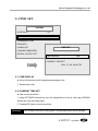
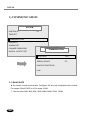
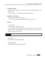
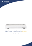
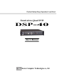
Perfect Safety! Easy Operation! Low Price! Stand-alone Quad DVR DSP-40 User’s Manual Korea Computer Technologies co., ltd. 1) This Manual is made for user of DSP-40. 2) This Manual includes features, handling method and setup of DSP-40. 3) This Manual must be read before using DSP-40. 4) If you have any question or have any difficulty in using, please contact your agency. Korea Computer Technologies, CO., LTD KCT B/D, 111-3, YANGJAE-DONG, SECHO-GU, SEOUL, KOREA (Tel) +82-2-575-2331 (FAX) +82-2-575-5450 http://www.kct21.com CONTENTS 0. Warning ··························································································2 1. Introduction·····················································································3 ■ Features ········································································································ 3 ■ Mainly Functions ··························································································· 4 ■ Names of each parts ····················································································· 5 2. Installation ······················································································7 3. Using Method ··············································································· 11 ■ ■ ■ ■ Booting ········································································································ 11 Bypass········································································································· 12 Recording ···································································································· 17 Replay ········································································································· 20 4. SETUP ·························································································23 ■ ■ ■ ■ Configuration SYSTEM ··············································································· 26 Configuration CAMERA ·············································································· 34 Configuration RECORD ·············································································· 36 OUTLINE of Setup items············································································· 40 5. Network ························································································41 ■ ‘DVR ETHERNET’ program for LAN ··························································· 42 ■ ‘DVR DIALUP’ program for serial port, modem ·········································· 47 ■ ‘DVR CONFIRM’ program for verify captured image ·································· 51 6. Specifications ···············································································53 7. Recording Table············································································54 8. APPENDIX ···················································································55 ■ ■ ■ ■ SELECTION OF NTSC/PAL········································································ 55 Installation of additional HDD······································································ 56 Pan/Tilt, Zoom, Focus ················································································· 58 Many DVR connected to One IP ································································· 60 9. Troubleshooting ············································································62 DSP-40 WARNING Thank you for choosing DSP-40. Before installation and use, please read and understand following instructions for your safety. Please install the product only after finding a suitable installment place. z Please install on a flat surface. z Please install in place with good ventilation Do not install in the following place z Sensitive to the vibration z Exposed to direct light z Heavy moisture Please do not put heavy materials on the equipment being installed. Please refer to the manual before using the recorder. Remember that the power cord may cause electric shock. z Please do not pull the power cord out of the electric outlet. z Please do not take out with wet hands. z The plug should be placed on safe places. Do not open the recorder. z It is very dangerous to touch the internal parts of the product. z Please contact the accredited shops that sell the product for repairs. Danger of explosion if battery is incorrectly replaced. Replace only with the same or equivalent type recommended by the manufacturer. Dispose of used batteries according to the manufacturer’s instructions. 2 Korea Computer Technologies, co., ltd Introduction 1. Features 1) This system is developed the first of the world that can record 4-channel at the same time, and display moving-image in quad screen. 2) Each channel can be displayed up to 30fps, and maximum 120fps totally. 3) Using Wavelet algorithm, this system realizes compression/extraction in high resolution. 4) This system is NON-PC, Self-OS, Stand-alone type PC, so 9 offers easy installation and using method to user, 9 and makes no trouble, i.e., breakdown or system down that PC-based surveillance system often makes. 1. Introduction 3 DSP-40 2. Mainly Functions ■ various bypass display (realtime quad, single sequential, auto switching, freezing) ■ 4 channel recording at the same time. Recording max 120fps totally ■ Various recording method by record button, reservation, sensor, motion detection ■ Fast and easy search for recording data ■ 320X240 resolution, true color recording ■ Warning through Buzzer or Digital output in sensor detection ■ transmission, printing, and capture image with RS232C, MODEM and LAN ■ 4 digital input / 1 digital out ■ Max 4 HDD ■ NTSC/PAL camera, monitor ■ PAN/TILT, Zoom, Focus camera support ■ Camera signal loss detection 4 Korea Computer Technologies, co., ltd 3. Names of each parts The Front side Enter SETUP mode or select item ENTER ESC Move cursor up/down/left/right Zoom the specific area in the screen Display single screen by each button Cancel selection or return to previous item Direction Rec Recording / Recording stop ZOOM Play DISPLAY Replay / Pause Stop Replay. Stop FF QUAD Search by fast forward Display quad screen at the same time NEXT FREEZE AUTO Freeze displaying screen Auto switching / Auto switching stop Search by 1 frame forward PREV REW Run Indicator Power Switch Search by 1frame rewind Search by fast rewind Green light twinkling when power on Power On / Off 1. Introduction 5 DSP-40 The Rear side Camera input Connect camera cable Monitor input Lan led Connect monitor cable Emit light when lan connection and working Connect Lan cable Emit light when sensor in LAN port Sensor led Connect sensor and digital out Sensor in/out Connect RS232C cable RS232C port Connect power cable 6 AC Power Korea Computer Technologies, co., ltd Installation 1. Contents of product 1) Main system (Embedded HDD, optional max 4EA) 2) Power cable 3) User’s manual, host program CD 1EA - If you have shortage or defects of parts, please contact your agency. 2. Step of Installation The Rear Side 2) Monitor Output 3) Sensor IN / OUT 1) Camera Input 4) RS232C port 5) LAN port 2. Installation 6) AC Power 7 DSP-40 1) Camera connection Connect camera to CAMERA INPUT of backward of system. 2) Monitor connection Connect monitor to MONITOR OUTPUT of backward of system. 3) Sensor connection (optional) Connect sensor to SENSOR IN of backward of system. 4) Network connection (optional) Construct RS232C, Modem and LAN connection referring to below network connection diagram. 5) Power connection Connect power cable to power connection of backward of system, and turn on the power switch of forward of system. 3. Network connection and serial cable connection 1) RS232C serial connection RS232C 9pin 2 Rx Rx 2 3 Tx Tx 3 5 Gnd Gnd Female 8 9pin 5 Female Korea Computer Technologies, co., ltd 2) Modem(PSTN) connection PSTN TEL. line RS232C TEL. line External Modem 9pin 25pin 4 5 2 Rx Rx 2 3 Tx Tx 3 6 Gnd 8 7 20 Male Gnd 5 Female 3) LAN connection LAN ※ Use cross cable when direct connection between PC and DVR using LAN cable. 2. Installation 9 DSP-40 4. After installation 1) Bypass, recording, replay, sensor test Confirm if bypass screen is displayed well. Then record and replay some data referring to in this manual. And confirm if sensor record is possible by making any event. If any problem, contact your agency. 2) RS232C, Modem (PSTN), LAN connection test Confirm if network print function is possible connecting the system to host computer. If any problem, contact your agency. 10 Korea Computer Technologies, co., ltd Using Method Booting 1) When system is booting, the follow screen is displayed. PLEASE WAIT VIDEO INITIALIZE QUAD INITIALIZE ENCODER INITIALIZE DECODER INITIALIZE RTC INITIALIZE VOICE INITIALIZE LAN INITIALIZE SYSTEM BIOS VERSION 20011008-20010928 STARTING SYSTEM… NTSC OK OK OK OK OK NONE 2) The “OK” means process success, and ‘FAIL’ means process failure. 3) If one of items(except LAN and VERSION) is FAIL, system reboot. 4) When all is OK, booting status screen is disappeared and quad bypass screen is displayed.. 3. Using Method - Booting 11 DSP-40 Bypass Principle of operation method ▶ User can display camera input to screen immediately, and can select 1-screen mode or split-screen mode. ▶ Auto Switch, Freeze, Zoom mode available ▶ Current time, camera name, and system status (i.e., Recording, Zoom, Freeze, Sensor) is displayed into screen. ▶ User can change from bypass status to setup mode and replay mode. ▶ Recording can be started or finished in the middle of bypass mode. If motion detection function is valid, blue recording icon is displayed. Refer to motion detection setup item in the SETUP mode in this manual. ▶Icon list 12 : Recording(RED) : Motion Detect(BLUE) : ZOOM : Freeze : Sensor : Switching Korea Computer Technologies, co., ltd 1. Quad Screen - If user press QUAD button in bypass status, the button emits light and quad screen is displayed. HDD-Status bar Display used quantity of HDD Display current time Current time 2001. 08. 01. 12:34:56 CAMERA 1 CAMERA 2 CAMERA 3 CAMERA 4 Display zoom in/out status ZOOM Camera name Recording On/Off Display recording on/off (blue means motion detect ready) Display freeze status Display sensor status Display camera name installed each channel. FREEZE Sensor In/Out 3. Using Method - Bypass 13 DSP-40 2. 1-Channel Screen - If user press camera button in bypass status, not in zoom or freeze mode, 1-channel screen is displayed. Display current time SWITCHING Display switching on/off Current time 2000. 01. 01. 12:34:56 Sensor In/Out Display Sensor status CAMERA 1 Camera Name Display camera name installed each channel FREEZE ZOOM Display freeze on/off Display zoom status Recording Display Recording status On/Off (blue means motion detect ready) 14 Korea Computer Technologies, co., ltd 3. Operation Method Freezing screen Auto Switching Zoom Screen AUTO FREEZE QUAD DISPLAY Cancel Direction ZOOM ENTER ESC Each Camera Quad screen Enter / Setup ▶ Screen Auto Switching (1-Channel screen mode only) 1) If user press AUTO button in 1-channel screen mode, the screen is auto switched according to switching gap of configuration in SETUP mode. (referring to p35.) (If user press AUTO button in quad screen mode, the screen mode is changed to 1channel mode and the screen is auto switched.) 2) In auto switching status, AUTO button emits light and auto switching icon is displayed. 3) In auto switching status, if user press AUTO button again, go back 1-channel screen. ▶FREEZE : display freeze-frame 1) In 1-channel screen mode, if user press FREEZE button, the screen displays freeze-frame. And if it is auto switching mode, auto switching stop immediately,(If freeze screen mode is deactivate, auto switching restarts,) In Freeze mode, the FREEZE button emits light and Freeze-icon is displayed in the screen. 2) In quad screen mode, if user press FREEZE button, the FREEZE button emits light. Then, pressing each camera button, the camera button emits light and freeze-icon is displayed with freeze-frame. 3) If user press freezed camera button or freeze button again, FREEZE mode is finished. 3. Using Method - Bypass 15 DSP-40 ▶zoom : selected area is zoomed (Quad screen mode only) 1) If user press zoom button, the button emits light and zoom area selection rectangle is displayed. 2) Using direction key, move zoom area. 3) Pressing enter key, selected area is zoomed and zoom-icon is displayed in up-left of each screen. 4) Using direction key, user can move select rectangle at the zoom-in status. 5) Pressing Esc, go back previous status. ▶HDD-Status Bar : Display used quantity of HDD 1) Red means used quantity and white means unused quantity. 2) The HDD-status bar is displayed as the number of HDD. Each HDD-status bar indicates quantity of each HDD. If HDD is not installed or not formatted, HDD-status bar is not displayed. 3) When ‘Auto delete’ is activated, recording is possible even though HDD is full. Then, HDD-status bar is displayed red entirely, only recording location of HDD is marked white. 4) The HDD-status bar is not displayed In AUTO SWITCHING / FREEZE / ZOOM / PTZ mode. 5) ‘Esc’ + ‘UP arrow’ : Display HDD-status bar ‘ESC’ + ‘DOWN arrow’ : Do not display HDD-status bar ▶Adjusting BRIGHT and CONTRAST of the Each Channel 1) Just touch ESC + DISPLAY n (n=1,2,3,4) then you can find the follow box which show BRIGHT and CONTRAST of selected Channel. CAMERA 1 BRIGHT 128 CONTRAST 216 2) Using UP/DOWN direction key for adjusting BRIGHT, and Using LEFT/RIGHT direction key for adjusting CONTRAST. 3) Using ZOOM key for default value(BRIGHT=128, CONTRAST=216). 4) Using ESC key for exit. 16 Korea Computer Technologies, co., ltd Recording Principle of operation method ▶ Recording method includes 1) button recording by user, 2) reserved recording by configured schedule, 3) recording by event of sensor. ▶ If motion detection function is valid, blue recording icon is displayed. If motion detection event occurs, blue changes to red. User can set up if motion detection is valid or not in the setup mode. Refer to appropriate part of this manual.(p37) ▶ If you change recording setup value in setup mode, you must finish record by record button, and restart record by record button. 3. Using Method - Recording 17 DSP-40 1. Recording by Button 1) If user press recording button, the button emits light, recording icon is displayed, and recording starts immediately. 2) Recording by button can be started in any status(bypass, replay and setup mode), but not in password input screen. 3) Pressing recording button again in recording mode, recording finishes and the button light is disabled and displayed icon is erased. 2. Reserved Recording 1) According to day of the week : by setting specific time range ▶ User can set enable reserved recording function on not each weekday (from Monday to Friday), Saturday, Sunday. ▶ User can set start time and end time of recording by hour and minute unit. ▶ Refer to appropriate part of this manual.(p38) 2) According to specific day : by setting specific time range ▶ Max 8 time-range can be set. ▶ User can set start time and end time of recording by month, day, hour and minute unit. ▶ Refer to appropriate part of this manual.(p38) 3. Recording by Event of Sensor 1) If event of sensor arises, recording starts in the channel connected that sensor. 2) Recording keeps up until the time set in setup mode, RECORD→SENSOR TIMEOUT item.(p38) 3) With event of sensor, the sensor-icon is displayed in the screen connected sensor 18 Korea Computer Technologies, co., ltd 4. Recording by Motion Detection 1) In the setup mode, if RECORD MOTION DETECTION SENSITIVITY item is not "NONE"(p37), motion detection is valid and color of recording icon is blue. 2) Objects in the screen move more than motion detection sensitivity, recording by motion detection start. If recording by motion detection occurs, recording icon changes to red from blue. 3) User can set up recording time after motion detection event. 4) Specific setting of Motion detection sensitivity and time is in the setup mode of this manual.(p37) 3. Using Method - Recording 19 DSP-40 Replay Principle of operation method ▶ In the bypass mode, pressing replay button, the screen changes to setting of replay start time screen. ▶ Select replay start time to play. ▶ And Pressing replay button again, replay starts. ▶ Search wanted screen by following method. ▶ If user press STOP button in replaying screen, replaying screen changes to setting of replay stat time screen. ▶ If user press STOP in setting of replaying start time screen, replay mode is finished. 20 Korea Computer Technologies, co., ltd 1. Setting of replay start time PLAY START FROM 2000. 01. 01. 00:00:00 RECORDED FROM 2000. 01. 01. 00:00:00 TO 2000. 01. 01. 12:34:56 ▶ Start time of replay is ending time of last replay. (If it is the first time of replay, displayed start time is head of recording time.) ▶ Setting of replay start time 1) Set by field ① Replay start time can be set by year, month, day, hour, minute, second unit. ② Using LEFT/RIGHT direction key, user can move between each field. And Using UP/DOWN direction key, value can be changed. ③ Default field is minute field. 2) Set continuously ① This is the quick method of changing replay start time, pressing REW, FF, PREV and NEXT button. ② Pressing REW button, replay start time changes forward quickly. And pressing FF button, replay start time changes backward quickly. ③ Pressing PREV button, replay start time changes forward by 1 second. And pressing NEXT button, replay start time changes backward by 1 second. 3. Using Method - Replay 21 DSP-40 2. Start of replay ▶ In the screen of replay start time setting, pressing PLAY button, then replay starts from the setting time. 3. Replay ▶Stop replay : Pressing STOP button in replay screen, replay stops and go back to the screen of replay start time setting. ▶Pause replay : Pressing STOP button in replay screen each time, the mode changes from PLAY to PAUSE, or from PAUSE to PLAY. ▶REW/FF : ① Pressing REW of FF button in replay screen, the mode changes fast rewind or fast replay. ② Just touch REW key then you can find the figures like 5,10,20, 30 and 60 on the left top of picture which can show you the max 60 times speed. FF is same too. ③ Pressing PLAY button in high speed replay, mode return to normal speed replay. ④ In the PAUSE status, pressing REW or FF for a while will change speed of replay. ▶PREV/NEXT : ① Pressing PREV or NEXT button in replay screen, play screen changes backward or forward by 1 frame. ② At this time, the mode always changes to PAUSE regardless of previous mode. 22 Korea Computer Technologies, co., ltd SETUP Principle of operation method ▷ Pressing ENTER/SETUP button in the bypass mode, changes to setup mode. ▷ Using UP/DOWN selection key, select the item to set. ▷ Button is displayed in selected item. ▷ Pressing ENTER button, go to lower grade item of selected item. ▷ When lower grade item is not exist, pressing ENTER button changes the condition of selected item to modifiable. ▷ In the modifiable condition, user can change value of item using direction key. ▷ Pressing ESC, go back previous status. ▷ Modified setup configuration is applied to system when the setup mode finishes. 4. SETUP 23 DSP-40 0. Input Password INPUT YOUR PASSWORD PASSWORD : USING DISPLAY KEY INPUT 8-DIGIT PASSWORD ▶User must input password to enter SETUP mode. ▶Password is composed of 8 digit number consisting integer from 1 to 4. (Factory default is 12341234. Do change password and use!) ▶Pressing display key from No.1 to No.4, input password. System displays "*" at the screen. ▶Pressing ESC button while input password, input cancels and return to bypass screen. ▶If input matches current password, setup mode starts automatically. ▶ If input does not match current password, below screen is displayed. Pressing ESC button, return to bypass screen. Confirm your password and retry. INPUT YOUR PASSWORD PASSWORD : WRONG PASSWORD ... PRESS ▼ESC▼ TO RETURN 24 Korea Computer Technologies, co., ltd ※ Common operation method ▶ SETUP mode is composed of three part, SYSTEM, CAMERA, RECORD. Pressing ENTER at each part, lower grade is displayed. SETUP SYSTEM CAMERA RECORD ▶ In lower grade, - Using direction key, select item. - Pressing ENTER, selected item is changeable and flashing. - Using direction key, set value. - Pressing ESC, go back previous status. ※ Outline of SETUP menu is At last of this SETUP item, . That is useful to understand SETUP menu. 4. SETUP 25 DSP-40 1. SYSTEM 1) SYSTEM ID SYSTEM SYSTEM ID 01 TIME SET COMMUNICATION DISK INFO ALARM LIST CHANGE PASSWORD DIGITAL OUTPUT SET ▶ Using several systems at the same time, user can set ID. ① Value from 0 to 99 can be used. ② default value is 00. 26 Korea Computer Technologies, co., ltd 2) TIME SET SYSTEM SYSTEM ID 01 TIME SET COMMUNICATION DISK INFO ALARM LIST TIME SET CHANGE PASSWORD DIGITAL OUTPUT SET TIME DISPLAY ON CURRENT TIME SET 2001. 07. 06. 09:00 FRI 2-1) TIME DISPLAY ▶ Set up if current time up-left of bypass screen displays or not. ① Default value is ON. 2-2) CURRENT TIME SET ▶ User can set current time. ① Using LEFT/RIGHT direction key, user can change field to be set up. And using UP/DOWN direction key, user can change value. ③ Pressing ESC button, set new current time. Warning! If you change current time in using system, recorded data can be heavily damaged. 4. SETUP - system 27 DSP-40 3) COMMUNICATION SYSTEM SYSTEM ID 01 TIME SET COMMUNICATION DISK INFO ALARM LIST COMMUNICATION COMMUNICATION CHANGE PASSWORD DIGITAL OUTPUT SET BAUD RATE 1152 SERIAL DEVICE PC PAN/TILR PROTOCOL LAN 3-1) BAUD RATE ▶ Set velocity of serial communication. Two figures, '00' at the tail of displayed value is omitted. For example, if BAUD RATE is 1152, it means 115200. ① User can select 2400, 4800, 9600, 19200, 28800, 38400, 57600, 115200. 28 Korea Computer Technologies, co., ltd 3-2) SERIAL DEVICE ▶ This system have 1 RS232C port. The port is made for PC and MODEM communication, and PAN/TILT control. ① Refer to explanation of Network(p8) and PAN/TILT(p63) in this manual. 3-3) PAN/TILT PROTOCOL ▶ Select the protocol used in PAN/TILT receiver. ① You can not select the number displayed with NONE.(Now support 3 protocol) 3-4) LAN (1) IP ADDRESS ▶ Select IP address used by LAN networking. ① IP address must be between 0 and 255. If user select the value out of range, warning message, "SELECT VALUE BETWEEN 0 AND 255", displayed. This message will be disappeared if the right value is selected. Warning! IP address can be used in LAN networking only after DVR system rebooting (2) GATEWAY ▶ Select GATEWAY used by LAN networking. (3) SUBNET MASK ▶ Select SUBNET MASK used by LAN networking. 4. SETUP - system 29 DSP-40 4) DISK INFO SYSTEM SYSTEM ID 01 TIME SET COMMUNICATION DISK INFO ALARM LIST DISK INFO CHANGE PASSWORD DIGITAL OUTPUT SET DISK 1 20.5GB 22.5% USED DISK 2 NO DISK DISK 3 NO DISK DISK 4 NO DISK SELECT DISK AND PRESS ENTER TO FORMAT ▶ Display disk information, i.e., if it is installed or not, disk storage, record condition. ▶ Display contents ① Disk is not installed : NO DISK ② Disk is not formatted : UNFORMATTED ③ Disk is in Use : ratio of used disk storage to total disk storage Warning! In time of auto-erasing record mode(p36), used storage always 100%, but recording is possible continuously. 30 Korea Computer Technologies, co., ltd 4-1) DISK FORMAT ▶Using UP/DOWN direction key, select disk to be formatted. ▶Pressing ENTER button, confirm message is displayed, and pressing again, disk formatting starts. ▶Formatting procedure is displayed by the ratio of formatted storage to total storage. ▶When the formatting finishes, the information of disk is displayed. ▶ If user attempt to format disk while recording, message "Formatting DISK 1 FAILED"(in case of disk #1) is displayed and format fails. Stop recording and retry format. Warning! Formatting disk erase all data forever, so you must be very careful. 5) ALARM LIST SYSTEM SYSTEM ID 01 TIME SET COMMUNICATION ALARM LIST DISK INFO 1 : 2001. 07. 06 11:03:20 CAM1 ALARM LIST 2 : 2001. 07. 06 14:23:38 CAM4 CHANGE PASSWORD 3 : 2001. 07. 06 16:03:16 CAM3 DIGITAL OUTPUT SET 4 : 2001. 07. 06 20:33:19 CAM2 5 : 2001. 07. 06 20:33:20 CAM4 6 : 2001. 07. 06 20:43:50 CAM4 7 : 2001. 07. 07 09:03:20 CAM1 8 : 2001. 07. 07 11:23:42 CAM3 ▶ Show sensor input history. 4. SETUP - system 31 DSP-40 6) CHANGE PASSWORD SYSTEM SYSTEM ID 01 TIME SET COMMUNICATION DISK INFO CHANGE PASSWORD ALARM LIST CHANGE PASSWORD CURRENT PASSWORD -------- NEW PASSWORD -------- DIGITAL OUTPUT SET NEW PASSWORD AGAIN -------- ▶Change current password to new password. ▶Pressing ESC button while input, input value is invalidated, and return to previous screen. ① Using display key, input 8 digit number consisting integer from 1 to 4. Using UP/DOWN direction key, input value in all 3 item. ② Input password does not match with current password, message "WRONG CURRENT PASSWORD" is displayed, and return to previous screen. ③ Though input password matches with current password, if input value in "NEW PASSWORD" is not similar to the value in "NEW PASSWORD AGAIN", message "PASSWORD NOT CHANGED" is displayed and return to previous screen. ④ If all value is inputted successfully, message "PASSWORD CHANGED SUCCESSFULLY" is displayed, and return to previous screen. New password is valid at the next setup mode. Warning! - When mode return from SETUP to Bypass,, New password is renewed, - Forgetting password, ask help to your agency. 32 Korea Computer Technologies, co., ltd 7) DIGITAL OUTPUT SET SYSTEM SYSTEM ID 01 TIME SET COMMUNICATION DISK INFO DIGITAL OUTPUT SET ALARM LIST CHANGE PASSWORD SENSOR 1 2 3 4 BUZZER ON ON ON ON DIGITAL OUTPUT SET TIME 10 OUTPUT ON TIME 10 ON ON ON ▶When sensor on, buzzer embedded in the system or output device in the digital output port works. Regardless of setup, back led of the system is turned on. ▶In this setup menu, user can determine if buzzer and digital output works or not on each sensor input. Besides, after sensor input, how long it keeps up (sec unit) without sensor input. ① In case of BUZZER and OUTPUT menu, using LEFT/RIGHT direction key, user can change field to be set up. Using UP/DOWN direction key, select ON or OFF. ② Default value is ON. ③ In case of TIME menu, using UP/DOWN direction key, user can increase/decrease value. ④ Value from 0 to 30(sec) can be used. default value is 10. 4. SETUP - system 33 DSP-40 2. CAMERA 1) INSTALLED CAMERA CAMERA INSTALLED CAMERA CC-- CAMERA 1 NAME STREET CAMERA 2 NAME DOOR CAMERA 3 NAME DESK 1 CAMERA 4 NAME DESK 2 CAMERA NAME DISPLAY ON SWITCHING TERM 03 ▶ Set up channel which is really installed camera among valid 4 channel. And classify Black/White camera and color camera. ① Using UP/DOWN direction key, changes status of selected camera. If you want to use camera, select 'C' or 'B'. If you don’t want to use, select symbol ‘-‘. ② Default status is using all cameras as color camera. Warning! 34 If each camera set C or B is unplugged, embedded buzzer works. Korea Computer Technologies, co., ltd 2) CAMERA NAME CAMERA INSTALLED CAMERA CC-- CAMERA 1 NAME STREET CAMERA 2 NAME DOOR CAMERA 3 NAME DESK 1 CAMERA 4 NAME DESK 2 CAMERA NAME DISPLAY ON SWITCHING TERM 03 ▶Set up camera name to be displayed in screen. ① Using LEFT/RIGHT direction key, select character to be set up. Selected character twinkles.. ② Using UP/DOWN direction key, changes character. English character, number, special symbol can be used. Default form is this : “CAMERA(camera number)” 3) CAMERA NAME DISPLAY ▶ Set up if current time in the bypass screen displays or not.. ① Using UP/DOWN direction key, select ON or OFF. ② Default selection is ON. 4) SWITCHING TERM ▶ Set up switching term by second unit. ① from 1 to 10 sec can be used.. Default value is 5. 4. SETUP - camera 35 DSP-40 3. RECORD RECORD RECORD FRAME 30 QUALITY 01 AUTO DELETE NO RECORD ON BOOT UP OFF MOTION DETECTION SENSOR TIMEOUT 03 RESERVED RECORDING 1) RECORD FRAME ▶ Set up compression rate of image to be recorded Set up record frame per second. ① From 1 to 30 can be used. Default value is 30. 2) QUALITY ▶ Set up compression rate of image to be recorded. ① If the quality value get smaller, screen quality get better and image data get bigger. ② From 1 to 10 can be used. Default value is 1. 3) AUTO DELETE ▶ Set up if auto delete function is valid or not. ▶ When hard disk is full in recording mode, Selecting NO, recording stops when hard disk is full in recording mode and Selecting YES, old data is deleted automatically. 36 Korea Computer Technologies, co., ltd 4) RECORD ON BOOT UP ▶ Set up if recording starts by itself on boot up or not. ① Selecting ON, recording starts automatically on boot up. ② Default selection is OFF. 5) MOTION DETECTION RECORD RECORD FRAME 30 QUALITY 01 AUTO DELETE NO RECORD ON BOOT UP OFF MOTION DETECTION SENSOR TIMEOUT RESERVED RECORDING MOTION DETECTION SENSITIVITY 03 NONE CONTINUE TIME 10 ▶ Motion detection means that recording starts automatically when moving object in the screen is detected. User can set up SENSITIVITY and CONTINUE TIME for motion detection in this section. ① User can select SENSITIVITY item as "VERY LOW", "LOW", "MEDIUM", "HIGH", "VERY HIGH". If SENSITIVITY is higher, recording starts automatically by less variation of moving object. ② If SENSITIVITY is NONE, motion detection is not valid. ③ CONTINUE TIME means recording time(sec) after motion detection event. ④ In case of CONTINUE TIME item, From 0 to 30 can be used. If CONTINUE TIME is 0, system records at a moment when motion is detected. 4. SETUP - record 37 DSP-40 6) SENSOR TIMEOUT ▶ Set up duration time(sec) of recording in case of sensor event. ① from 1 to 10 can be used. Default value is 10. 7) RESERVED RECORDING RESERVED RECORDING WEEKDAYS ON 00:00 - 00:00 SATURDAY ON 00:00 - 00:00 SUNDAY ON 00:00 - 00:00 SPECIFIC DAYS ▶ Set up schedule of reserved recording. ▶ This includes record according to day of week and record according to specific day. ▶ Use minute unit. ▶ Only if user select ON, reserved recording is valid. 7-1) WEEKDAYS ▶ Set up schedule of recording during weekdays. ① Using UP/DOWN direction key, select ON or OFF of function. ② Then, Using LEFT/RIGHT direction key, move recording time setup field.(Only Function On available) ③ Set up start time and finish time of recording up to hour and minute. 38 Korea Computer Technologies, co., ltd 7-2) SATURDAY ▶ Set up schedule of recording during Saturday. ① Set up method of this function is similar to recording during weekdays. 7-3) SUNDAY ▶ Set up schedule of recording during Sunday. ① Set up method of this function is similar to recording during weekdays. 7-4) SPECIFIC DAYS SPECIFIC DAYS 1 : ON 2 : ON 3 : ON 4 : ON 5 : ON 6 : ON 7 : ON 8 : ON 00. 00. 00:00 - 00. 00. 00:00 00. 00. 00:00 - 00. 00. 00:00 00. 00. 00:00 - 00. 00. 00:00 00. 00. 00:00 - 00. 00. 00:00 00. 00. 00:00 - 00. 00. 00:00 00. 00. 00:00 - 00. 00. 00:00 00. 00. 00:00 - 00. 00. 00:00 00. 00. 00:00 - 00. 00. 00:00 ▶ Set up schedule of recording during specific period of time. ▶ Use minute unit. ▶ Only if user select ON, reserved recording is valid. ▶ Set up start time and finish time of recording up to day, hour and minute. ▶ If finish time is earlier than start time, recording doesn’t start. 4. SETUP - record 39 DSP-40 ※ The Outline of SETUP menu SETUP SYSTEM SYSTEM ID TIME SET COMMUNICATION DISK INFO ALARM LIST CHANGE PASSWORD DIGITAL OUTPUT SET CAMERA INSTALLED CAMERA CAMERA 1 NAME CAMERA 2 NAME CAMERA 3 NAME CAMERA 4 NAME CAMERA NAME DISPLAY SWITCHING TERM RECORD RECORD FRAME QUALITY AUTO DELETE RECORD ON BOOT UP MOTION DETECTION SENSOR TIMEOUT RESERVED RECORDING 40 TIME DISPLAY CURRENT TIME SET BAUD RATE SERIAL DEVICE PAN/TILT PROTOCOL LAN FORMAT BUZZER OUTPUT SENSITIVITY CONTINUE TIME WEEKDAYS SATURDAY SUNDAY SPECIFIC DAYS IP GATEWAY SUBNETMASK PORT Korea Computer Technologies, co., ltd NETWORK Principle of operation method ▷ If user set up host program(“DVR ETHERNET”, "DVR DIALUP") in PC, between local system and host PC user can transmit moving image and can print specific frame. Microsoft Windows 98/ME have to be installed in the Host PC. ▷ Each program has different use as below. "DVR ETHERNET" : used for networking by LAN "DVR DIALUP" : used for networking by serial port and modem ▷ User can transmit and print 4-channel bypass image and recorded image from local system to host PC through RS232C, MODEM or LAN. ▷ User can save specific frame transmitted. (RS232C, MODEM). ▷ User can verify the captured image by “DVR CONFIRM” 5. Network 41 DSP-40 Host Program “DVR ETHERNET” for LAN 1) Start Microsoft Windows 98/ME, and put Software CD into PC CD drive. 2) Execute SETUP.EXE in “DVR ETHERNET” folder. And click NEXT button. 3) Input name and company. Then click NEXT button. 4) Select location to install, Then click NEXT button. 5) Select location to make at “start-program”. 6) Confirm information, Then click NEXT button. Installation is progressing. 7) With finishing installation, Program group “KCT” and execution file “DVR ETHERNET” is formed. 1. Set up DVR ETHERNET 1) Setup IP ADDRESS ① Clicking "Remote" menu, below screen is displayed. ② Set the name of remote DVR at "REMOTE NAME" item. ③ Set the IP address of remote DVR at "REMOTE IP ADDR". Selected IP address at 29 page in this manual must be the same as this IP address. ④ You can set each IP for many DVR (if need). Next time, only select correct IP for DVR you want to connect.(using direction key) ⑤ You need password for connecting remote DVR. That is same to password for entering setup mode in remote DVR. 42 Korea Computer Technologies, co., ltd 2) Setup Save path ① Clicking "Save" menu, sub menu “Setup”, below screen is displayed. ② Set the directory path to save screen, when you capture bypass or recorded screen. 2. Transmission method though LAN using "DVR ETHERNET” 1) Preparation of transmission ① Construct network referring to page 9 in this manual, and execute DVR ETHERNET program. ② Referring to previous "1. Set up DVR ETHERNET", finish set up. Then Transmission is ready. ③ Clicking "Connection" button, "On Line" message displayed in status bar and pc will be connected with remote DVR. ④ Clicking "Disconnection" menu, "Off Line" message will be displayed in status bar and pc disconnected with remote DVR . And sometimes below message is displayed. "TIMEOUT" item in this message means the time until forced disconnecting when the disconnecting is delayed by the unexpected situation. If this item becomes 0, LAN communication is forced to disconnect. Clicking “connection”, “BYPASS”, or “PLAYBACK” button, ※ case of displaying “Remote is connected with other user” : means another user controls remote DVR through “DVR Ethernet” now. Multi user can’t control remote DVR at the same time. ※ case of displaying “Remote replay work active” : means remote DVR is playing now. While remote DVR is playing, user can’t play remote DVR through “DVR ETHERNET”. Retry later. 5. Network – DVR ETHERNET 43 DSP-40 2) Transmitting bypass image. ① Clicking "Live Mode" button, bypass image will be transmitted. ② During transmission, "Live Mode" button is changed to "Stop" button. Clicking this, transmission stops. ③ If the Camera connected the DVR supports Pan, Tilt, Zoom, Focus function, you can use that function through this program in the remote area. (referring p56 about PTZ function) Select the camera to control and use PTZ function by clicking arrow key. 44 Korea Computer Technologies, co., ltd 3) Transmitting recorded image ① Clicking "Replay Mode" button, setting screen of play back start time is displayed Record start time and end time in the Remote DVR PLAY Start time PAUSE Play speed STOP ② Select replay start time and press "PLAY" button, playback starts. Press "PAUSE" button during playback, playback will be paused. ③ Press "STOP" button, playback stops, and the setting screen of play back start time will be disappeared. ④ The value of "SPEED" item has 5 level, from VERY SLOW to VERY FAST. 5. Network – DVR ETHERNET 45 DSP-40 3. Capture image ① Click the right button of the mouse on the each camera screen you want to capture. ② Clicking ‘capture’, displaying screen(bypass or recorded image) is captured. Captured image is saved in selected directory(referring to ‘1.setup DVR ETHERNET’) as ‘c#_yyyy_MM_dd-hh_mm_ss’ type.(ex : c1_2001_11_20-14_30_28) If you select ‘auto save’, automatic save is activated and the image is captured continuously. 46 Korea Computer Technologies, co., ltd Host Program “DVR DIALUP” for Serial port and Modem 1) Start Microsoft Windows 98/ME, and put Software CD into PC CD drive. 2) Execute SETUP.EXE in “DVR DIALUP” folder. And click NEXT button. 3) Input name and company. Then click NEXT button. 4) Select location to install, Then click NEXT button. 5) Select location to make at “start-program”. 6) Confirm information, Then click NEXT button. Installation is progressing. 7) With finishing installation, Program group “KCT” and execution file “DVR ETHERNET” is formed. 1. Set up "DVR DIALUP" ① Clicking “Communication”, sub menu of “Setup” menu, you can set up DEVICE and BAUD RATE. In case of modem communication, select the name of modem installed PC in "DEVICE". In case of serial communication, select port. (BAUD RATE must be same as DVR’s) ② Clicking “Option”, sub menu of “Setup” menu, you can set up if title and recording time of the frame is included or not in the time of saving that frame. And you can select your monitor mode as NTSC or PAL. (if setup is incorrectly, screen is displayed strangely.) 5. Network – DVR CONFIRM 47 DSP-40 ③ Clicking “Phonebook”, sub menu of “Setup” menu, you can set up remote name and telephone number using in modem communication. ④ Clicking "Update" after inputting name and telephone number, system registers that automatically. If you want to modify name or number, click "Update" after modify. When updating, confirm message as below is displayed. If you want to delete name, select name and click "Delete". 2. Transmission, save, print image through serial port 1) Preparation of transmission ① Construct network referring to page 9 in this manual, and execute DVR DIALUP program. ② Referring to previous "1. Set up “DVR DIALUP”, set up "DEVICE" and "BAUD RATE". In the status bar, message "online" is displayed. 2) Transmission, save, and print bypass image ① Use only bypass mode of DVR. ② Clicking “Request Current Image”, sub menu of “Commands” menu, bypass image is transmitted. Transmission rate is displayed. Transmission repeats over and over periodically. 48 Korea Computer Technologies, co., ltd ③ Double clicking the transmitted frame, “Title” window is displayed, in which you can fix the name of that frame. Fixed name is displayed in the status bar. ④ Clicking “Save as”, sub menu of “File” menu, you can save that frame as BMP format. ⑤ Clicking “Stop Current Image”, sub menu of “Commands” menu, transmission stops. Warning! Don’t operate at local DVR while transmission. 3) Transmission, save, and print recorded image ① In the replay mode, press PLAY/PAUSE button, it changes to PAUSE state. Then, press ENTER button, transmission from local system to host PC starts. (All button here is in DVR) ② And, transmission rate is displayed in the status bar of the host program. With transmission finishing, “completed..” is displayed. ③ Save and print bypass image is the same as ③ of item 2) follows. 5. Network – DVR CONFIRM 49 DSP-40 3. Transmission, save, print image through MODEM 1) Preparation of transmission ① Construct network referring to page 8 in this manual, and execute "DVRDIALUP.EXE". ② Referring to previous "1. Set up “DVR DIALUP", set up "DEVICE" and "BAUD RATE". In the status bar, message "online" is displayed. ③ If MODEM is initialized successfully, the name of MODEM is displayed in the status bar. ④ Clicking “Connect”, sub menu of “Connect” menu, the name and status of remote are displayed. Remote name is set up in “Phonebook”, sub menu of “Setup” menu. Refer to previous "1. Set up host program". ⑤ Clicking “Connect”, connection trial starts. And clicking “Disconnect”, connection trial fails. ⑥ In the middle of connecting, clicking “Disconnect”, sub menu of “Connect” menu, connection ends. 2) Transmission, save, and print bypass image This is the same as using serial network. Refer to page 48 of this manual. 50 Korea Computer Technologies, co., ltd “DVR CONFIRM” for Verify Captured Image forged or not. 1) Install the ‘DVR Confirm’ program in the software CD and execute it. 2) Open image to verify. (If it is not the image captured by our DVR, “This is NOT the image captured by our DVR!” message is displayed.) 5. Network – DVR CONFIRM 51 DSP-40 3) Then click ‘Verify’ button. 4) If it is the original image captured by our DVR, “This is the ORIGINAL image captured image” message is displayed. 5) If it is forged image, “This is forged image” message is displayed and forged area is filled with RED color. 52 Korea Computer Technologies, co., ltd Specifications System DSP-40 Operation type Stand-alone, Self operation system Save HDD Max 4 EA available Camera input 4CH (NTSC/PAL) Video output 1CH (NTSC/PAL) Resolution 320 × 240, 640 x 480, true color Recording speed 30fps, MAX 120fps, Available for change Recording type Wavelet, Recording 4CH at the same time Sensor input 4 ports Digital output 1 port Humidity 10~90% Temperature 5~40°C Network ETHERNET interface, RS232C, Modem PAN/TILT Support ( Now support 8 protocol ) Power 100W Voltage Free Voltage (AC 100~240V / 50~60Hz) Volume Weight DSP-40 435(W) ( 88(H) ( 385(D) 7.7kg (excepting HDD weight) 6. Specifications 53 DSP-40 Recording Time Table In case of recording in 4channel at the same time (Quality=1) FPS 1 3 5 10 15 30 40GB 347 h 115 h 69 h 34 h 23 h 11 h 80GB 694 h 230 h 138 h 68 h 46 h 22 h 120GB 1388 h 460 h 276 h 136 h 92 h 44 h 160GB 2776 h 920 h 552 h 272 h 184 h 88 h HDD ※ This Recording Time is changeable according to use environment and recording image. Use as reference. 54 Korea Computer Technologies, co., ltd APPENDIX Selection of NTSC/PAL User can selects NTSC/PAL type by setting jumper. But user need not change that except special case, because factory set the correct jumper for selling region. The Rear Side MONITOR OUT JP1 CAMERA IN NTSC POWER PAL BATT1 The Front side 8. APPENDIX 55 DSP-40 Installation of additional HDD 1. Embedded HDD 1) HDD is embedded in this system. 2) Max 4 HDD can be installed in each system. Warning! User must format new HDD before use that. 2. Installation of additional HDD 1) Turn off the system, and disconnect attached cable. 2) Unfasten the bolts in the top and side of system, and open referring to this picture. open 56 Korea Computer Technologies, co., ltd 3) You can see installed HDD. Additional HDD can be installed in specified position as this picture. The rear side HDD2 HDD4 (Slave) (Slave) HDD1 HDD3 (Master (Master POWER The front side 4) Connect data cable and power cable to additional HDD. ▶ Set up master/slave of HDD by jumper setting. ▶ Connect cables refer to this picture. The rear side The front side Power Cable Data Cable HDD1 HDD2 Connecting to HDD1 Connecting to HDD3 ▶ In case of HDD3 and HDD4 is the same thing. 8. APPENDIX 57 DSP-40 5) Put together case again. 6) Confirm HDD information ▶ Put on the system and press SETUP button, select system item. ▶ Using UP/DOWN direction key, select DISK INFO item. ▶ Confirm if new HDD is displayed, and using ratio is 0% or not. ▶ If the using ratio of any HDD is not 0%, it must be formatted. You can refer to page 30 of this manual. Pan/Tilt, Zoom, Focus 1. Introduction 1) User can handle the remote camera to move left/right(Pan) and up/down(Tilt). Besides, make camera zoom in/out and move focus of the camera near/far. 2) This function is valid only the camera with a built-in pan/tilt receiver, Now support 8 protocol, ①CNB SMART PTZ, ②SAERIM SSR-100, ③PELCO D PROTOCOL ④PELCO P PROTOCOL ⑤IKEGAWA SM-RX100 ⑥DONGYANG UNITECH ⑦CRYPTO A120 ⑧SUNGJIN 3) This function is valid only if SYSTEM->SERIAL PORT->DEVICE item value in the setup mode is PAN/TILT, and PROTOCOL item value is correct with user’s camera. (referring to p28,29) Refer to camera’s manual for more information. 4) If you want to enlarge screen in Pan/Tilt, Zoom, Focus mode, press ‘zoom’ button. Pressing ‘zoom’ button again, then return to original quad screen. 5) Pressing ‘ESC’ button to exit from Pan/Tilt, Zoom, Focus mode. 58 Korea Computer Technologies, co., ltd 2. Pan/Tilt 1) In 4-CH bypass screen, press REW button, user can enter Pan/Tilt mode. 2) Use direction key, select camera to be applied, and press ENTER button. 3) Press LEFT/RIGHT direction key, the camera move left/right. (Pan) 4) Press UP/DOWN direction key, the camera move up/down. (Tilt) 3. Zoom 1) In 4-CH bypass screen, press PREV button, user can enter Zoom mode. 2) Use direction key, select camera to be applied, and press ENTER button. 3) Press LEFT/RIGHT direction key, the camera zooms out/in. 4. Focus 1) In 4-CH bypass screen, press PREV button, user can enter Focus mode. 2) Use direction key, select camera to be applied, and press ENTER button. 3) Press LEFT/RIGHT direction key, the focus of camera moves far/near. 5. Power on/off 1) In 4-CH bypass screen, press one of REW, PREV, NEXT button, user can enter one of Pan/Tilt, Zoom, Focus mode. 2) Use direction key, select camera to be applied, and press ENTER button. 3) Press FF button, selected camera turns off. 4) If camera turns off, press FF button, selected camera turns on. 8. APPENDIX 59 DSP-40 Many DVR connected to One Static IP 1) You can connect many DVR to one static IP by setting each ‘SYSTEM ID’ at each DVR. So if you have only one static IP, you can watch many DVR in the remote PC. 2) Construct system like follow example. (example : static ID is 61.78.64.163) 192.168.123.0 61.78.64.163 (Static IP) ID 00 192.168.123.1 ID 01 ROUTER . . . . . 192.168.123.10 Set virtual IP at each ID 10 Set SYSTEM ID at DVR according to your each DVR(p.26) network rule.(p.29) 3) You can connect each DVR by setting IP and selecting SYSTEM ID. 60 Korea Computer Technologies, co., ltd 4) Install “DVR ETHERNET” program in the remote PC. Set up not virtual IP but static IP (case of above example : not 192.168.123.xxx but 61.78.64.163) and select SYSTEM ID of DVR you want to connect.(referring to p.42) 5) But first of all, you must set up PORT FORWARDING in your ROUTER. Reffering to your ROUTER’s manual, forward port 2000 to DVR’s IP set as ID 00(case of above example : 192.168.123.0), and port 2001 to DVR’s IP set as ID 01(case of above example : 192.168.123.1). Like this method, forward port 2002 to ID 02, port 2003 to ID 03,…. Ask to network administrator for more information. 8. APPENDIX 61 DSP-40 ♠ Troubleshooting ♠ Continuous warning sound, “beep~” ☞ If camera cable is unplugged from DVR, beep sound. Check this. (p34) ☞ If sensor in, beep sound. Check sensor in or not. (p33) Blank screen (or Shaking screen). ☞ Check connection camera and monitor. (p8) ☞ Check NTSC/PAL type of DVR setup. (p60) No recording ☞ If HDD is full and ‘auto delete’ function is not activate, recording is not work. Check this.(p36) No color even though color camera ☞ Check camera setup is color or black.(p35) No Auto Switching ☞ Auto switching pause while Freezing. Check screen Freeze or not. (15p) No control through Network ☞ Check setup of DVR and host program. (BAUD RATE must have the same value at DVR and program setup. When serial connection, DVR’s network setup must be PC. When modem connection, DVR’s network setup must be MODEM. Refer to SETUP item on this manual for more information.) ☞ Please remove and reinstall host program. 62 Digital Video Recorder DSP-40 Korea Computer Technologies ADDRESS KCT B/D 111-3 YANGJAE-DONG, SEOCHO-GU, SEOUL, KOREA TEL. +82-2-575-2331 FAX +82-2-575-5450 Web site http://www.kct21.com/