1
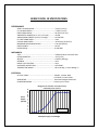
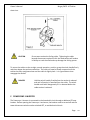
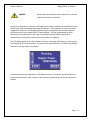
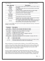
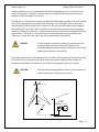
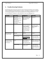
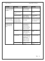
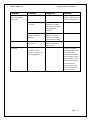
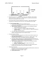
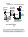
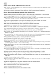
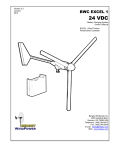
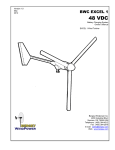
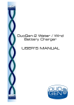
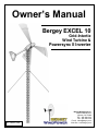
Owner’s Manual Bergey EXCEL 10 Grid-Intertie Wind Turbine & Powersync II Inverter Rev. 1 March, 2011 Bergey Windpower Co. 2200 Industrial Blvd. Norman, OK 73069 TEL: 405-364-4212 Fax: 405-364-2078 E-mail: [email protected] Web Site: www.bergey.com BERGEY EXCEL 10 SPECIFICATIONS PERFORMANCE START-UP WIND SPEED……………………………………………. 5 mph (2.2 m/s) CUT-IN WIND SPEED………………………………………………... 5 mph (2.2 m/s) RATED WIND SPEED……………………………………………...… 26 mph (11.6 m/s) AWEA RATED POWER (at 11 m/s or 25 mph) ……….…. 8.9 kW AWEA ANNUAL ENERGY (at 5 m/s average) ……………. 13,600 kWh CUT-OUT WIND SPEED………………………………………..…… none FURLING WIND SPEED……………………………………………… 36-40 mph (16-18 m/s) MAXIMUM DESIGN WIND SPEED………………………….…. 134 mph (60m/s) RATED POWER………………………………………………………... 10 kW ROTOR SPEED……………………………………………………….... 0-400 RPM MECHANICAL TYPE………………………………………………………………………… 3-Blade Upwind, Horizontal-Axis ROTOR DIAMETER……………………………………………………. 23 ft (7.0m) WEIGHT……….…………………………………………………….……. 1020 lbs (460 kgs) GEARBOX …………………………………………………………….…. none BLADE PITCH CONTROL……………………………………..….... none OVERSPEED PROTECTION………………………………….….... AUTOFURL® TEMPERATURE RANGE…………………………………………… -40 to 140 deg. F (-40 to 60deg. C) ELECTRICAL OUTPUT FORM………………………………………………..…….. 240VAC, 1-Phase, 60Hz or 220VAC, 1-Phase, 50Hz GENERATOR ………………………………………………………….. Permanent Magnet Alternator POWER PROCESSOR …………………………………………..…. Powersync II Inverter Bergey Excel 10 Power Curve (Sea Level) USDA Data per IEC 61400-12 Power Output (AC kW) 14 13 12 11 10 9 8 7 6 5 4 3 2 1 0 1 m/s = 2.237 mph 0 1 2 3 4 5 6 7 8 9 10 11 12 13 14 15 16 17 18 19 20 Wind Speed (m/s) at Hub Height Owner’s Manual Bergey EXCEL 10 Turbine INTRODUCTION This manual contains important information concerning your Bergey EXCEL 10 wind turbine system and its operational characteristics. We strongly recommend that you read and familiarize yourself with its contents. At several points in this manual items of special interest or significant impact are highlighted by one of the following symbols: DANGER Hazards or unsafe practices that could cause personal injury or death. WARNING Hazards or unsafe practices which could cause product damage. NOTE Significant points of interest. Serial Numbers Each Bergey EXCEL 10 wind turbine has a serial number located on the tower adapter. The turbine serial number can also be found on the outside of the shipping carton and on the warranty registration card. We recommend that the serial number be copied to this manual for possible future reference. Bergey EXCEL 10 Serial No.: ________________________ The Powersync II inverter has a serial number label on its right side. We recommend that this serial number also be copied to this manual. Powersync II Serial No.: __________________________ Page 2 Owner’s Manual Bergey EXCEL 10 Turbine Table of Contents Section 1 Title Page No. System Description A. Rotor System B. Alternator C. Mainframe D. Slip-Rings and Brushes E. Tail Assemble and AutoFurl® Operation F. Spinner and Nacelle G. Powersync II Inverter 2 System Operation A. Normal Operation B. High Winds - AutoFurl® C. Unloaded Operation D. Manual Furling E. Furling Procedure F. Powersync II Inverter 3 Installation A. B. C. D. Bergey EXCEL 10 Wind Turbine and Tower Fused Disconnect Switch Wire Sizes Powersync II Inverter 4 5 5 5 5 6 6 6 7 7 8 8 9 9 10 14 14 14 14 14 4 Inspections and Maintenance 16 5 Trouble-Shooting Problems 19 6 Appendix 22 A. Warranty B. Warranty Registration C. Vendors Manual for Powersync II inverter 23 24 25 Page 3 Owner’s Manual Bergey EXCEL 10 Turbine 1. SYSTEM DESCRIPTION The Bergey EXCEL 10 is an upwind horizontal-axis wind turbine designed for distributed generation applications, connected to the power grid on the customer’s side of the utility meter. The complete unit consists of the following major components, as shown in the figure below: 1. 2. 3. 4. 5. Spinner PowerFlex® Blades Alternator Mainframe Yaw Bearing 6. 7. 8. 9. 10. Slip-ring and Brushes Tail Assembly Nacelle Assembly Furling Winch Powersync II Inverter Alternator Nacelle Spinner Rotor Blades Mainframe Assembly Tail Assembly Powersync II Inverter Page 4 Owner’s Manual Bergey EXCEL 10 Turbine A. ROTOR SYSTEM The rotor system consists of three PowerFlex® fiberglass blades. Acting like aircraft wings, the blades convert the energy of the wind into rotational forces that drive the alternator. The PowerFlex® blades are rigidly attached to the alternator and they are fixed pitch. The Excel 10 rotor blades have a proprietary airfoil, the BWC-7, which was custom designed to provide high efficiency and low noise. The blades for the EXCEL 10 are extremely strong because they are made in a “pultrusion” process that puts more high-strength glass fibers in the structure than any other molding technique. This contributes to their long life and toughness. Blade sets are carefully matched for balance at the factory to ensure smooth operation of the wind turbine. Each blade has a serial number inscribed on its root pad at the inboard end. B. ALTERNATOR The alternator converts the rotational energy of the rotor into electricity. The alternator utilizes permanent magnets and has an inverted configuration in that the outside housing rotates, while the internal windings are stationary. It was specifically designed for the Bergey EXCEL 10 and produces power at low speeds, eliminating the need for a speed-increasing gearbox. Since it uses permanent magnets, the alternator is generating voltage whenever the rotor is turning. DANGER The output wiring of the BWC EXCEL presents shock hazard whenever the rotor is turning. Caution must be exercised at all times to avoid electrical shock. C. MAINFRAME The mainframe is the structural backbone of the wind turbine. It serves as the attachment point for the yaw bearing and the housing for the yaw-axis slip-ring brushes. The yaw-axis is the full 360 degree pivot that allows the turbine to freely align itself to the wind direction. D. SLIP-RINGS AND BRUSHES The slip-rings and brushes conduct the electricity generated in the alternator from the moving (as it orients with the direction) wind turbine to the fixed tower wiring. The slip-rings are Page 5 Owner’s Manual Bergey EXCEL 10 Turbine enclosed in a metallic housing to help protect them from lightning. E. TAIL ASSEMBLY AND AUTOFURL OPERATION The tail assembly keeps the rotor aligned into the wind at wind speeds below approximately 35 miles per hour (16 m/s). At about 35 mph the AutoFurl® action turns the rotor away from the wind to limit the rotor speed in high winds. The tail appears to fold, but in reality the tail stays stationary as the rotor turns sideways to the wind. The rotor furls to a maximum angle of 75 degrees (limited by rubber tail stops), so that the unit continues to produce power in high winds. When the high winds subside, the AutoFurl® system automatically restores the turbine into the normal straight position. The rotor continues to spin even in very high winds and this actually makes the blades stiffer. The AutoFurl® system works whether or not the Powersync II inverter is on or not. Unlike many other turbines designs, the Bergey EXCEL 10 can operate safely without an electrical load connected to the turbine. F. SPINNER AND NACELLE The spinner (nose cone) and nacelle provide additional weather protection for the bearings and the slip-ring assembly. The nacelle also improves lightning protection. G. Powersync II Inverter The UL-approved Powersync II inverter converts the “variable AC” from the Bergey EXCEL 10 turbine into utility grade electricity so that it can be connected to the wiring in your home. This conversion requires sophisticated electronics and is designed to operate automatically. The Powersync II has a digital display that provides information on the status of the system, its current output power, and its cumulative energy production. Page 6 Owner’s Manual Bergey EXCEL 10 Turbine 2. SYSTEM OPERATION A. NORMAL OPERATION The Bergey EXCEL 10 produces utility compatible power in the form of 240VAC, 60 Hz, single phase electricity (208 VAC/60Hz and 220 VAC/50 Hz options are available). It is connected through the Powersync II inverter to the utility distribution network in the same manner as household appliances. When the wind speed is too low to operate the wind turbine, all of the electrical power needed for the home will be supplied by the utility company. During these idle periods the Powersync II will consume approximately 0.3 kilowatt-hours of electricity per day. When the system begins producing power, the amount of power which must be purchased from the utility is reduced by an amount equal to the output of the wind system. From the perspective of the utility company the wind system output reduces the electrical load they have to supply, just as if you turned off lights and appliances. The output of the wind system fluctuates with the speed of the wind so the instantaneous amount of electricity being saved will be constantly changing. Quite often your home will be served simultaneously by the utility and your Bergey wind turbine. When the output of the wind system exceeds the power requirements of the house the excess electricity is sold back to the utility. Both the consumer’s right to interconnect a wind system and the utilities obligation to purchase excess power are prescribed by federal law (PURPA, Section 210). The amount you will be credited or paid for this excess production varies stateto-state and sometimes utility-to-utility. If your utility company offers “net metering” then your meter is allowed to turn backwards so that you essentially bank energy, at full value, for less windy periods. This banking can be done over a month or over a year depending on the policy of your state or your utility. If you do not get “net metering” then you will have a second utility meter to register excess production and your utility will pay or credit you for this, typically at less than full value. If your utility experiences an outage (blackout) the wind system will cease to produce power so that it does not present an electrical safety hazard to utility repair crews. Although the wind turbine will continue to operate, no power will be transferred from the Powersync II inverter to your circuit breaker panel. When utility power is restored, the Powersync II will automatically return the wind system to full working status following a five minute delay and then a two minute countdown. These time delays are dictated in the UL standards required by the utilities. The rotor of the EXCEL 10 should begin to rotate when the wind speed reaches approximately 8 mph (3.6 m/s). Once started, the rotor may continue to turn in winds below 5 mph (2.2 m/s), but the system will not be producing power below this wind speed. Page 7 Owner’s Manual NOTE Bergey EXCEL 10 Turbine All operational wind speeds given assume steady winds, sealevel conditions and moderate temperatures. Hot weather, high altitude, turbulence and gusting winds will reduce system performance. The rotor speed will increase with increasing wind speed and the system will produce a higher output. This output increases rapidly because the energy available in the wind varies as the third power (cube) of the wind speed. For example, if the wind speed increased form 5 mph to 10 mph, a factor of two, the energy in the wind would increase from one unit to eight units, a factor of eight (2 to the 3rd power). One result of this relationship is that there is very little energy available in light winds. For the average site, winds in the range of 12-20 mph (5.5 – 9 m/s) will provide most of the system’s energy production on an annual basis. B. HIGH WINDS - AUTOFURL® During periods of high wind speeds the AutoFurl® system will automatically protect the wind turbine. Furling means that the rotor is turned away from the wind. When furled, the power output of the turbine will be reduced. In winds between 33 mph (15 m/s) and 45 mph (20 m/s) it is normal for the turbine to repeatedly furl and then unfurl and then furl again. During intermittent cycling the turbine may produce output surges up to 13,000 watts. C. UNLOADED OPERATION If an abnormal condition occurs on the utility line, such as a voltage fluctuation or a complete interruption, the Powersync II inverter will automatically disconnect the wind turbine from the power grid. If sufficient wind is present, the rotor will continue to operate. Since it is unloaded it will spin at a higher speed and some increase in blade sound is to be expected. This is a perfectly safe and permissible condition as the AutoFurl system will continue to protect the turbine. DANGER During unloaded operation the alternator can still generate high voltages, so the EXCEL 10 electrical system should be handled with the same caution used during normal operation. In order to enhance the systems reliability, the power output of the Excel is limited to approximately 12.5 kilowatts. Since this output is reached at 31 mph (14 m/s), the rotor will become progressively unloaded as wind speeds increase up to the furling point at Page 8 Owner’s Manual Bergey EXCEL 10 Turbine approximately 35 mph (15.6 m/s). D. MANUAL FURLING The Bergey EXCEL 10 is designed for unattended operation over an extended period of time. Exceptional situations may occur, however, in which the wind turbine should be manually furled. These situations include: 1. EXCESSIVE VIBRATION - Uneven ice build-up, ice shedding, or blade damage may cause the wind turbine to experience excessive vibration. Always furl the turbine as soon as an increase in vibration is detected. Any new or excessive vibration in the turbine when ice is not present should be investigated immediately. 2. UNUSUAL SOUND - If the turbine begins making clinking, growling, or other unusual sound it should be furled and fully inspected as soon as possible. 3. INSPECTION AND MAINTENANCE - Whenever someone has to climb the tower the wind turbine must be manually furled, and the alternator dynamically braked (ie. electrically shorted), even if the wind speed is very low. Manual furling of the EXCEL 10 is accomplished by operating the furling winch located at the base of the tower. The winch cable is connected to the tail boom such that as the cable is tightened the tail “folds” and the rotor is pulled away form the wind. Furling the wind turbine will not stop the rotor completely and it may take some time for the rotor to be pulled around away from the wind. Fully furled the rotor will still be partly facing into the wind and will normally turn at a reduced rate. The rotor can only be brought to a complete stop by shorting the output leads of the turbine. DANGER Do not attempt to furl the wind turbine or approach any part of the tower when there is lightning in the area. E. FURLING PROCEDURE The furling winch is located at the base of the wind turbine tower. To furl the wind turbine, first make sure that the winch ratchet is engaged (a strong clicking sound should be heard as the handle is turned). The winch handle may then be turned until the tail comes to rest against its rubber stop. When the stop is reached the tail will stop rotating towards the blades and the force required to turn the handle will greatly increase. When fully furled, the tail will have come around approximately 70 degrees: it does not come around parallel to the blades. The turbine may not come out of the wind immediately because the rotor forces will sometimes resist the sideways force acting of the tail. This situation will correct itself after a Page 9 Owner’s Manual Bergey EXCEL 10 Turbine short time. CAUTION Do not over tension the furling cable. Tightening the cable beyond the amount required to furl the wind turbine will reduce its ability to track the wind and may damage the furling system. To return the turbine to the straight, normal operation, position, grasp the winch handle firmly and then release the ratchet mechanism. The cable can now be slowly unwound until the turbine has fully straightened out and the cable is slightly slack. It is a good idea to then reengage the ratchet. DANGER Hold the winch handle firmly before the ratchet is released and until all tension is removed from the cable. The winch handle could whirl dangerously if it is released before the cable tension is reduced. F. POWERSYNC II INVERTER The Powersync II inverter is connected to the household circuit through a dedicated 70 amp breaker. Before opening the Powersync II enclosure, the breaker must be turned off and the tower disconnect switch must be switched OFF, to avoid electrical shock. Page 10 Owner’s Manual DANGER Bergey EXCEL 10 Turbine Always remember that the system operates at 240 volts, so electrical shocks can be fatal! Using the utility grid as a reference, the Powersync II inverter converts the output of the wind turbine into utility-compatible alternating current (AC). The Powersync II inverter has been designed for automatic, unattended operation and it is programmed to provide maximum performance from your Bergey EXCEL 10 wind turbine. It is also programmed to safely disconnect the wind turbine in the event of a problem with the utility power and to automatically reconnect the turbine after the problem is remedied. The LCD digital display on the front of the Powersync II provides information on the status of your Bergey EXCEL 10 wind turbine. The contrast can be adjusted UP or DOWN using hidden buttons on the right side of the display. In normal operation the Powersync II will show the status as “Running” and will display the instantaneous Output Power in Watts. Other operating modes that may be indicated are as follows: Page 11 Owner’s Manual Bergey EXCEL 10 Turbine Using the Up and DOWN arrows you can scroll through the additional Powersync II information available, as shown below. When the Powersync II is starting up after initialization, or after the RESET button has been pushed, or after a power outage, it will go through a 300 second (5 minute) countdown that is required by UL 1741. This UL standard also dictates high and low limits for utility voltage and frequency, outside of which the inverter is required to shut down until they return to the acceptable range. This is called a FAULT condition. There are a number of possible FAULT conditions during which the Powersync II will be protecting itself or the power grid. When a FAULT occurs the Powersync II will shut down (no power production) and a Fault Code will be displayed on the digital display. A list of the Fault Codes can be found in the detailed instructions for the Powersync II inverter provided in the Page 12 Owner’s Manual Bergey EXCEL 10 Turbine Appendix. FAULTS will reset themselves automatically; assuming the underlying cause of the fault has been cleared, unless the inverter experiences three (3) FAULTS of any type in a one hour period. In this case a manual RESET is required on the digital display. CAUTION If a manual reset is required we highly recommend that you check the FAULT CODE list for indications that there is an equipment or wiring problem that needs addressing. One unique feature of the Powersync II inverter is its Soft Grid power limiting capability that can reduce the number of nuisance FAULTS on weak power lines during periods of high turbine power output. On a weak power line the EXCEL 10 wind turbine can, on a windy day, raise the local utility voltage above the UL 1741 threshold, causing a FAULT. The Soft Grid feature tries to prevent these FAULTS by reducing power output from the wind turbine. When the Powersync II is in this mode the digital display will show “Soft Grid”. The STOP pad on the digital display will shut down the Powersync II inverter. Press the RESET pad to restart (which will start the 300 sec. countdown). If the circuit breaker in your home or business load center (circuit breaker panel) trips, it should be reset by first switching it to the OFF position and then to the ON position. If the breaker trips again immediately, or if it continues to trip after brief periods of normal operation, switch the breaker OFF and contact your Bergey dealer for assistance. The following recommendations will help ensure the safe operation of the Powersync II inverter: 1. Keep all sources of moisture away from the Powersync II enclosure. 2. Do not work near the Powersync II with gasoline, paint thinner, or any material which produces flammable vapor. Do not store flammable materials near the Powersynce II enclosure. 3. Do not open the Powersync II enclosure unless the circuit breaker and Accessible Disconnect Switch (ADC) at the base of the tower have been switched OFF. Note that even with the circuit breaker and ADC switched OFF, a shock hazard will still be present inside the Powersync II enclosure for approximately 15 minutes (as the capacitor voltage drains down). 4. Do not block airflow around the Powersync II enclosure in any way. A six-inch clearance must be maintained around the sides, top, and bottom of the enclosure for adequate air circulation. Page 13 Owner’s Manual Bergey EXCEL 10 Turbine 3. INSTALLATION Please use the following instructions in assembling and commissioning your system. If you need any additional information, please contact us. A. BWC EXCEL WIND TURBINE and TOWER Please refer to the BWC EXCEL Installation Manual, and any addendum for the specific tower design, for instructions on installing the wind turbine and tower. B. FUSED DISCONNECT SWITCH The electrical output of the wind turbine is a three-phase alternating current (AC). We strongly recommend the installation of a fused three-phase AC disconnect switch between the wind turbine and the Powersync II, as shown in the drawing on Page 16. This switch is commonly referred to as an Accessible Disconnect Switch (ADC) and most utilities will require one to be installed. A 60A weather-tight switch box with 45A fuses for the 240 VAC, 60Hz or 220VAC, 50Hz system is recommended. The fuses will help protect the alternator in the event of a wiring, controller, or load short circuit. The fused disconnect switch is normally installed at the base of the tower. CAUTION Do not install a “short circuiting switch” that will provide dynamic braking of the alternator. These switches can be easily misused, leading to serious damage to the alternator. Such damage is not covered by the BWC warranty. C. WIRE RUN AND WIRE SIZES Please refer to the BWC EXCEL Installation Manual for recommended wire and conduit sizes for the tower-to-Powersync II wire run. Refer to the row labeled “BWC Excel-S” for appropriate wire sizes. D. POWERSYNC II INVERTER The Powersync II inverter should be installed indoors, near the main breaker enclosure if possible. The Powersync II is designed to operate in a clean environment and should never be Page 14 Owner’s Manual Bergey EXCEL 10 Turbine installed outdoors as it is not weatherproof and will be damaged by rain. A minimum of six inches of clearance is required on the top, bottom and sides of the Powersync II to ensure adequate air flow through the enclosure. The Powersync II should be connected to a dedicated 70A breaker installed in the main breaker box. System grounding is accomplished by attaching a wire, # 8 AWG minimum, from the grounding lug inside the Powersync II enclosure to the panel ground inside the main breaker box. Additionally, the tower “bond” ground wire should be connected to the grounding lug inside the Powersync II enclosure. A typical system wiring schematic for the Bergey EXCEL 10 is shown below. The three AC connections from the wind turbine can be connected to the Powersync II terminals in any order; there is no required phase orientation. DANGER Do not attempt to make the Powersync II connections with energized leads. Always have the wind turbine fully disconnected and the circuit breaker switched to “off” before making the Powersync II connections. All wiring should conform to the National Electric Code or other governing local electrical code. The use of electrical conduit for wiring between components is highly recommended. All terminations should be coated with an anti-oxidation compound to prevent corrosion. CAUTION All loads should be equipped with fuses or circuit breakers to avoid hazards from accidental short circuits. 10 kW Wind Turbine 24 m (80 ft) GuyedTower Safety Switch Cummulative Production Meter Power AC Load Processing Center Unit (Inverter) Page 15 Owner’s Manual Bergey EXCEL 10 Turbine 4. INSPECTIONS AND MAINTENANCE The Bergey EXCEL 10 turbine and tower should be inspected 30 days after installation, and then again 180 days after installation. Following these two inspections the installation should be inspected every two years and after any particularly severe weather. Inspections should be done on days when the wind is below 16 mph (7 m/s). Check List for Inspections 1. Inspect each of the anchor points. Ensure that all hardware is secure and the guy wires are properly tensioned. Check to ensure that no strands are broken and the turnbuckle safety cables are in place. 2. Furl the wind turbine and check that the damper restricts the tail's unfurling to a period of at least three seconds when the winch cable is rapidly unwound. 3. Disconnect the inverter, furl the turbine and short the alternator using the procedure given in the installation manuals. Climb the tower. Always use proper safety climbing gear and safe climbing practices. 4. Inspect the blades for: A. Cracks outboard of the hub pad, in the blade pultrusion itself. Cracks in the molded hub pad are normal after a few weeks of operation and will not affect the strength or reliability of the blade. B. Condition of the leading edge protection tape. Torn or peeling tape will need replacing. C. Leading or trailing edge damage. D. Condition of the paint. 5. Remove the spinner and hang it from the machine. Check the torque on the blade nuts; the recommended value is 150 ft-lbs. Check the front bearing for seal integrity and grease loss. Reattach the spinner and check that it is secure. 6. Open the hatch on the nacelle. Use a small rope to lash the hatch open. 7. At the 180 day inspection only: Inspect the flanged connection between the mainframe and alternator. Check the torque on each of the bolts; the recommended value is 80 ft-lbs. Page 16 Owner’s Manual Bergey EXCEL 10 Turbine 8. Check the rear alternator bearing for seal integrity and grease loss. 9. Inspect the mainframe for cracks. 10. Remove the slip-ring cover plate. Make the following inspections: A. Check brushes for ease or movement in the brush holder. B. Check slip rings for signs of arcing damage. C. Check that no grease from the yaw bearings has leaked on to the slip-rings. 11. Inspect damper. Some leakage around the front seal is okay. 12. Inspect the furling cable (particularly at the ball end/fork attachment to the tail boom) and furling cable conduit. 13. Check for cracks or loose hardware on the tail boom and fin. 14. Check the tail pivot pin and particularly its fasteners. 15. Close the nacelle and check that all of its fasteners are secure. 16. While descending the tower, inspect the following: A. Check that the tower wiring is properly secure. B. Check all fasteners. C. Look for any cracks in the tower structure. D. Check the condition of the guy wire attachment. E. Check the furling cable. 17. Check the furling winch and make sure that the furling cable is not twisted up. If the cable is twisted up, check the swivel. 18. Check the connection on all ground rods and hardware. 19. Remove the alternator shorting connection. Check the disconnect switch. 20. Switch the disconnect switch to "OFF" and unfurl the wind turbine. Listen to the sound of the machine as it speeds up. No mechanical sounds, such as a "clunking" or "banging," should be heard. Also watch for any new or significant vibration. The turbine operation should be smooth. 21. Inspect the wire run, particularly all electrical connections. 22. Use a Meggar to check the three-phase wiring from the turbine to the controller (the procedure is the same as used for commissioning). Page 17 Owner’s Manual Bergey EXCEL 10 Turbine 23. Use a VOM to check that the three legs of the AC output of the wind turbine are balanced. 24. Check condition of all wiring connections into and out of the Powersync II. 25. Check the fan filters on the Powersync II. At the second annual inspection, and at each alternate inspection thereafter, the right nacelle half should be opened and the slip-ring cover removed. This will allow the condition of the brushes and slip-rings, and internal fasteners to be checked. DANGER Only qualified personnel with proper safety equipment should climb the tower. Never climb the tower when the rotor is turning. Page 18 Owner’s Manual Bergey EXCEL 10 Turbine 5. Trouble-Shooting Problems The following guide can help to pin-point the cause of operational problems with the Bergey EXCEL 10 wind turbine and the Powersync II inverter For problems or symptoms not found in the following listing please contact the Service Department at Bergey Windpower Co. at Tel. No. 1-405-364-4212, Telefax No. 1-405-364-2078, or E-mail: [email protected] Problem Cause(s) Diagnosis Remedy Broken furling cable 1. Over-tightening of furling cable 2. Jammed cable furling cable conduit 3. Leaving turbine furled for long periods 4. Swivel not installed or not working Tail damper failure When replacing cable check for free play inside furling cable conduit. Check swivel. Replace cable and conduit as indicated. Check for damper effectiveness by furling the turbine and then rapidly unwinding the furling cable. It should take at least three (3) seconds for the tail to return to the straight position. 1. Have leading edge tape inspected If damper fails the test, the turbine should be furled during high winds until the damper is replaced. 2. Blade (pultrusion) structural damage 2. Have blades inspected. Cracks outboard of the molded hub can lead to blade failure. 1. Uneven ice build-up on blades 1. Ice on turbine and tower. Turbine ran smoothly before ice storm. Slow rotor speed. 2. If blade damage is suspected, the turbine should be furled until it is inspected. Contact your dealer. 1. Do nothing – ice will dislodge in a few days. No need to furl the turbine. 2. Blade damage 2. No ice. Turbine ran smoothly before Oil stain at rear of nacelle Turbine makes an unusual blade sound, such as whistling or buzzing Rotor is unbalanced, causing the turbine to move slightly back and forth as it spins 1. Damaged blade leading edge tape 1. Replace tape as necessary 2. If blade damage is suspected, the turbine should be furled until it is inspected. Contact your dealer. Page 19 Owner’s Manual Bergey EXCEL 10 Turbine Problem Cause(s) Diagnosis Remedy Turbine makes a banging or rattling sound once per revolution, particularly at low speeds 1. Loose spinner 1. More likely on pre2004 turbines (when design was changed) 1. Have spinner inspected 2. Alternator rear bearing ring fasteners loose or missing 2. Requires inspection 2. Have alternator inspected 3. Alternator bearings 3. Excessive grease leakage. Squeaking sounds at low speed. Sound comes and goes, but occurs at the same wind speed(s) 3. Have alternator inspected Turbine makes a “fog horn” sound at certain, typically low, wind speeds Electro-mechanical interaction between alternator and inverter that causes transient vibrations in the turbine Turbine makes a continuous growling or rumbling sound, which reduces at higher wind speeds This is normal, but contact your dealer or the Bergey Service Department if the noise is excessive Switch fused disconnect on tower to OFF. If growling disappears an electrical problem is indicated. If growling continues a mechanical problem is indicated 1. Wiring fault 1. Check fuses. Check wiring for continuity, phase-to-phase fault, or short to ground. 1. Repair or replace as needed 2. Inverter fault 2. After completing the wiring check, disconnect the inverter and reconnect wiring to the turbine. If the noise disappears an inverter problem is indicated. 2. Contact your dealer 3. Alternator bearings 3. Check for excessive grease loss 3. Have the alternator inspected Page 20 Owner’s Manual Bergey EXCEL 10 Turbine Problem Cause(s) Diagnosis Remedy Rotor turns slowly and does not speed up in higher winds 1. Ice build-up on blades 1. Check for ice 1. Do nothing – ice will dislodge in a few days. No need to furl the turbine. 2. Short circuit in wiring or inverter 2. Open tower disconnect. If turbine spins freely an electrical system problem is indicated 2. Contact your dealer 3. Short circuit in tower wiring, slip-rings, or alternator 3. The most likely problem is a shorted alternator. Diagnosis requires tower climbing Rotor does not turn even when winds exceed 15 mph (6.7 m/s) 3. Contact your dealer Rotor does not turn at all Mechanical failure inside alternator Powersync II display not functioning 1. No power to inverter 2. Display or other inverter component not functioning properly Contact your dealer 1. Turn off utility power to inverter, using the dedicated breaker in your breaker panel, for a minimum of 20 seconds. Then turn power back on using the breaker. Wait 300 seconds (5 minutes). If inverter does not resume operation, with full display functionality, contact your dealer Page 21 Owner’s Manual Bergey EXCEL 10 Turbine Appendix Page 22 Owner’s Manual Bergey EXCEL 10 Turbine Page 23 Owner’s Manual Bergey EXCEL 10 Turbine Page 24 Owner’s Manual Bergey EXCEL 10 Turbine Powersync II - 240 VAC (AMFA-27) and Powersync II - 208 VAC (AMFA-29) Operator's Manual & Installation Instructions Rev. 2.6 Date: 22 November, 2010 Page 25 AMFA-27/AMFA-29 Operators Manual Permanently-connected, utility Interactive, single-phase, inverters Model AMFA-27 WIND TURBINE INVERTER (240 VAC nominal output) The phase angle between L1 and L2 is 180°. Line to Neutral is 120 VAC nominal. Model AMFA-29 WIND TURBINE INVERTER (208 VAC nominal output) The phase angle between L1 and L2 is 120°. Line to Neutral is 120 VAC nominal. USL - Evaluated to the requirements of the Standard for Safety for Inverters, Converters, Controllers and Interconnection System Equipment for Use with Distributed Energy Resources, UL 1741, 2nd Edition, dated January 28, 2010. CNL - Additionally evaluated to CAN/CSA C22.2 No. 107.1-1, "General Use Power Supplies." 3rd Edition, Dated September 1st, 2001 with revision through 2006. The Diversified Technology Inc. Model AMFA-27 and AMFA-29 inverters are intended for variable frequency un-rectified 3-phase AC input from Wind Powered Turbines. Table of Contents 1. Ratings 2. Important Safety Instructions 3. Installation a. Mounting b. Electrical Connections 4. Markings 5. Operation 6. Touch Screen Display a. Stop / Reset b. Status c. Faults d. Parameters 7. Equipment Maintenance Page 1 AMFA-27/AMFA-29 Operators Manual Ratings Turbine Input Input Voltage Maximum (3 Phase Input) Input Start Voltage Minimum Input Operating Voltage Range Input Frequency Maximum Input Current Maximum Input Short Circuit Current Maximum AC Backfeed Current to Input Source 400 VAC 30 VAC 200 to 400 VAC 400 Hz 40 Amps 462 Amps N/A Utility Interactive Output Continuous Output Power Maximum Continuous Output Power Tolerance Continuous Output Current Maximum Continuous Output Current Tolerance Output Voltage Nominal (Single Phase) Line-Line Operating Voltage Range Line-Line Output Voltage Nominal (Single Phase) Line-Neutral Operating Voltage Range Line-Neutral Voltage Measurement Tolerance Operating Frequency Nominal Operating Frequency Range Operating Frequency Measurement Tolerance Output Power Factor Temperature Range Normal Operation Output Over-Current Protection Maximum Output Fault Current Maximum Synchronization In-Rush Current Maximum Utility Interconnection Trip Time Time Measurement Tolerance Page 2 AMFA-27 AMFA-29 12000 KW 10400 KW +/-10% 50 Amps +/- 10% 240 VAC 208 VAC 212-264 184-228 120 VAC 106-132 VAC +/- 10 VAC 60 Hz 59.3 to 60.5 Hz +/- 0.5 Hz 0.95 +/- 0.05 -20ºC to 45ºC 80 Amps 1030 Amps 6.3 Amps 100 msec +/- 85 msec AMFA-27/AMFA-29 Operators Manual Important Safety Instructions SAVE THESE INSTRUCTIONS This manual contains important instructions for Model AMFA-27 and AMFA-29 that shall be followed during installation and maintenance of the inverter. The output field wiring terminal can be used for connection of a maximum of: One 1/0 AWG wire per terminal (1 wire for each line) The input field wiring terminal can be used for connection of a maximum of: One 2 AWG wire per terminal (1 wire per phase per terminal provided). The field-wiring terminals shall be connected using the following wire types: Copper Conductors Only (Input connection) Use No. 6 - 2 AWG, 90 °C copper wire only Copper, Aluminum or Copper-Clad Aluminum Conductors Only (Output connection) Use No. 6 – 1/0 AWG, 90 °C Copper Conductors Use No. 4 – 1/0 AWG, 90 °C Copper Clad Aluminum, or Aluminum Conductors. The following symbols are used as markings on this product with the following meanings: Equipment grounding conductor – This inverter is intended for operation in an indoor NEMA 1 compatible environment having a maximum ambient temperature of 45 degrees C. This unit or system is provided with fixed trip limits and shall not be aggregated above 30 kW on a single Point of Common Connection CAUTION To reduce the risk of fire, connect only to a circuit provided with 80 amperes maximum branch-circuit over-current protection in accordance with the National Electrical Code, ANSI/NFPA 70. Note that the input and output circuits are isolated from the enclosure. In accordance with Clause 15.2.1.1 of CAN/CSA-C22.2 No. 107.1, system grounding, when required by the Canadian Electrical Code, Part I, is the responsibility of the installer. Page 3 AMFA-27/AMFA-29 Operators Manual 2. Installation a. Mounting i. The enclosure, having a NEMA 1 rating, is designed for indoor installation. ii. The enclosure is provided with four mounting feet with 0.281” dia. mounting holes. iii. For mounting to a 0.10” thick metal surface, use M6, ¼-20 or ¼-28 bolts grade 3 or higher with nuts and flat washers. iv. For mounting to concrete, use M6 or ¼” bolts using concrete anchors with an 800 pound or greater tension rating. v. The required bolt length is such that the internal threads need to be 100% engaged. vi. The enclosure is to be oriented with the conduit openings facing toward the floor. vii. Enclosure ventilation is to be provided such that the following guidelines are satisfied. 1. Provide a minimum of 12 inches clearance to the air inlet filters. 2. Provide a minimum of 6 inches clearance to the outlet side vents. 3. Use in a well ventilated area within the maximum ambient temperature rating. Page 4 AMFA-27/AMFA-29 Operators Manual b. Electrical Connections are made to the unit via the holes in the bottom of the enclosure. Holes are sized for 1.5’’ rated conduit. Wiring methods in accordance with the National Electrical Code, ANSI/NFPA 70 are to be used. c. The input and output circuits are isolated from the enclosure. System grounding when required by the Canadian Electrical Code, Part I, is the responsibility of the installer. d. AC Output Connection (Utility) i. The AC output is single phase and not bonded to ground. ii. Connect the two single phase 240VAC wires to the dual fuse block located on the lower left side of the enclosure. iii. Tightening torque, allowable wire size, and type, for the Field-Wiring Terminals: 1. 100 lbf-in tightening torque maximum 2. 6 AWG to a maximum of 1/0 AWG for Copper Conductors Only 3. 4 AWG to a maximum of 1/0 AWG for Aluminum Or Copper-Clad Aluminum Conductors Only 4. Wire type – rated 90C minimum iv. The inverter’s earth ground connection must be bonded directly to the service entrance’s earth ground which in turn is bonded to neutral. e. AC Input Connection (Turbine) i. Connect the three phase turbine wires to the DIN rail terminal block located on the lower right side of the enclosure. ii. The inverter’s wind turbine input must be connected to a 3-phase “delta” or “wye” connection with the neutral not connected to earth ground (left floating). iii. The inverter must be provided with 3, UL listed fuses rated, 400 VAC minimum, 50 Amp maximum for proper protection from the wind turbine input to the unit as well as an appropriate UL listed fuse holder to accommodate the fuses. iv. Tightening torque, allowable wire size, and type, for the Field-Wiring Terminals: 1. 22 lbf-in tightening torque 2. 6 AWG - to a maximum of 2 AWG for Copper Conductors Only 3. Wire type – rated 90C minimum v. An input ground connection must be made between the inverter and the ground terminal of the tower disconnect, wire size minimum of 8 AWG." f. Earth Ground Connection i. Earth ground is to be connected to the two terminals provided inside the enclosure as indicated by the earth ground equipment marking. ii. Allowable wire size range is 8 AWG – 4 AWG. iii. 50 lbf-in tightening torque Page 5 AMFA-27/AMFA-29 Operators Manual g. Connection Example i. Surge arrestors are not required but are recommended for a minimum amount of lightning and surge protection. No lightning protection system provides complete protection. Lightning damage is not covered under your warranty. 3. Markings a. Enclosure: Type 1 – for INDOOR USE ONLY b. Earth ground is indicated by the following marking: 4. Operation This equipment is a UL 1741 certified Utility Interactive Inverter and complies with the requirements of IEEE1547 which is the standard for interconnecting distributed resources with electric power systems. The Normal Operation of the inverter is as follows: When single phase 240VAC is applied to the inverter, the display will power up and a message stating that the unit is initializing is shown. A countdown timer set for 5 minutes (300 seconds) starts before the inverter is ready to transfer power to the utility grid. The inverter will automatically transfer power to the utility when AC voltages in the range of 30VAC to 400VAC are present at the Turbine input. Page 6 AMFA-27/AMFA-29 Operators Manual 5. Touch Screen Display a. The touch screen display located on the front panel of the enclosure provides manual override and status of the inverter’s operation. The touch screen display also provides a Stop and a Reset button. The Stop button is used when it is desired to disconnect the inverter from the power grid and the wind turbine. After Stop is pressed the inverter will remain in a poweredup stand-by mode until Reset is pressed or Grid voltage is removed. When Reset is pressed the inverter will resume normal operation. b. Status i. Status of the inverters operation is shown on the lines one and two of the display. The following table lists the status messages that may appear. Status Message Description Waiting Initializing Waiting For Wind AC Running Running Fault Manual Stop Press Reset Fault Limit Press Reset The inverter has been reset or that the 5 minute countdown delay is in progress The voltage from the turbine is lower than the factory set auto-start voltage threshold The active rectifier is regulating the internal DC Boost voltage The inverter is transferring power to the utility grid A fault has occurred. See fault messages Disconnected Soft Grid The manual stop button has been pressed Three faults have occurred in an hours time Indicates that a communication problem exists between the display and the inverter. Check for bad cable connection. The inverter has detected that the output voltage is approaching the over voltage limit and is reducing its output to compensate for the less than ideal current carrying ability of grid connection. Page 7 AMFA-27/AMFA-29 c. Operators Manual Fault Messages i. Fault messages are displayed when a fault occurs and when the last fault parameter is selected. The following table is a list of possible faults that may be displayed. Fault Message Fault Code INTERNAL ERROR 10 DC OVER VOLT 1 DC OVER VOLT 2 1000 1500 DC UNDER VOLT 1250 AC OVER VOLT 2030 AC UNDER VOLT 2280 TURBINE PHASE 2500 OVER CURRENT 3000 OVER CURRENT 3020 OVER CURRENT 3050 OVER TEMP 4000 UNDER TEMP GROUND FAULT 4250 7000 AC UNDER FREQ 8000 AC OVER FREQ 8100 Description IGBT Desat or control logic fault. An occurrence of this fault requires that the unit be completely powered down to reset it. The DC Bus voltage has exceeded its maximum threshold The DC Input voltage has exceeded its maximum threshold The internal DC Boost voltage has dropped below its minimum threshold The AC line voltage has exceeded its maximum threshold The AC line voltage has dropped below its minimum threshold Indicates that there is a problem with one or more of the turbine input phases. Bad connection, missing phase. Phase A line current sensed by the converter module has exceeded its maximum current threshold Phase C line current sensed by the converter module has exceeded its maximum current threshold The DC Boost phase of the converter module has exceeded its maximum current threshold The internal high temperature threshold has been exceeded The internal low temperature threshold has been exceeded An input phase appears to be shorted to chassis ground The frequency of the utility grid voltage went out of range. The upper range threshold was crossed The frequency of the utility grid voltage went out of range. The lower range threshold was crossed Page 8 AMFA-27/AMFA-29 Operators Manual d. Parameters i. The Up and Down arrow that is visible on the left side of the touch screen display* is used to scroll through a list of parameters. The list of viewable parameters is as follows: Parameter Grid Voltage Grid Frequency Bus Voltage DC Current Turbine Volts Output Power Accum. Energy VRef IRef Last Fault Description Magnitude of the connected single phase grid voltage Frequency of the connected single phase grid voltage Magnitude of the actively rectified DC bus voltage Averaged value of the DC current Averaged value of the rectified AC voltage from the Input Output power displayed in watts Output Power accumulated over time of operation. Accuracy within 10%. Used for factory setup** Used for factory setup** Displays the last fault that occurred since the inverter was powered up along with a fault code that may be useful when troubleshooting. *A hidden feature of the display is the contrast adjustment. The right side of the display has invisible up and down arrows that can be used to increase and decrease the contrast of the display. **Vref is used as an index look-up into a virtual table used for a customizable power curve, the graph of which is configured by parameters 81 through 93, called Iref request values. The virtual size of the table is 768 points. The table parameters configure every 64th value of the look-up curve for Iref. Iref is the current request in counts for a given DC input voltage tracked by Vref. Using this configuration the inverter can be adjusted to provide any power curve required. 6. Equipment Maintenance a. Periodically check the ventilation screen for the cooling fans. When necessary, use a vacuum to clean the screen from the outside of the enclosure. Do not force air or spray water into the enclosure. b. The touch screen display may become dirty over time. To clean the display use clean water applied to a soft non-abrasive cloth. Water sprayed directly onto the display could possibly leak inside and cause damage. Dirt and fingerprints do not affect the operation of the touch screen display. Page 9