1
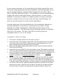
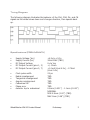
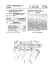
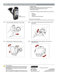
WW-02
WheelWatcher
Product Manual
Incremental quadrature encoder system
for gearhead motors
1 .0 3 8 / 3 1/ 2 0 0 5
W heelW atcher Features
<
<
<
<
<
<
<
<
easy installation
simple interface
preprinted 32 stripe self-adhesive reflective codewheel
hardwa re quadra ture decode w ith 4x multiply for 128 clocks per rotation
raw quadrature also provided
compa tible with Solarbotics GM-2, GM-3, GM -8, and GM -9 Gearh ead motors*
designed for use with standard injection-molded robot wheels – any color
code exam ple s for comm on rob ot controllers availab le
*GM-2 a nd GM -3 motors requ ire the use of the optional CS-100 Codewheel Spacer.
Description
The WW-02 WheelWatcher incremental encoder system enables robot
builders to quickly add closed-loop control to their robots. Both standard
ChA/ChB raw quadrature outputs (90° phase shift between channels), as
well as decoded Clock and Direction signals are provided. The clock signal
produces a 25:s pulse at each transition of ChA or ChB, providing a 4x
increase in resolution compared to the number of stripes – 128 clocks per
rotation – while the direction signal indicates the decoded direction of
rotation, making it very easy to add to any microcontroller.
W W -02 Parts List
1.
2.
3.
4.
5.
printed circuit board, preassembled
self-adhesive codewheel
6" four lead color-coded cable
two extra wires provided for use with raw-quadrature output
insulated washers
Installation
Proper spacing between the photodetectors and codewheel, as well as
alignment of the photodetectors to the codewheel, is essential to proper
operation.
WheelWatcher WW-02 Product Manual
Preliminary
2
Proper spacing depends on the board being held tightly against the top of
the motor using appropriate mounting hardware, and also depends on the
use of standard injection molded wheels designed for the GM-2, GM-3,
GM-8, and GM-9 gearhead motors. It is possible to use the WheelWatcher
system with other commercial wheels, custom wheels, or even to give
feedback on the rate of rotation or relative position of a leg or arm joint.
However, details of such use is up to the end user; Noetic Design, Inc.
does not provide support for such custom applications.
Accurate alignment of the photodetectors to the codewheel depends on
accurate placement of the sticker on the back of the wheel. It also
depends on reliable maintenance of that alignment by means of the
mounting hardware. The GM-series motor mounting holes are com patible
with #2 or #3 screws. The GM-3 and GM-9 mounting holes are
compatible with #2, #3, or #4 screws.
Installation Step by Step
1.
2.
3.
4.
5.
6.
7.
if the motor is already mounted on the robot, remove it
lower the board over the motor output shaft, with the shaft going into the largest
hole in the center of the WW-02, making sure the raised alignment pin on the
motor housing enters the matching hole on the board
Make sure the slightly raised area around the motor shaft fits entirely inside the
hole in the circuit board
mount the motor and WW-02 to the robot chassis, using 2-56 machine screws and
2-56 nuts; place insulated washers between the screw heads and the circuit board
wire up the cable to your microcontroller; black is ground, red is Vcc (regulated +5v
is recommended), and the rest are ChA, ChB, Dir, and Clk; see the Connector
Pinout for assembly and Interfacing Examples for details
For GM-2 or GM-3 motors: peel off the adhesive backing, then install the optional
CS-100 Codewheel Spacer onto the back of the wheel (the side into which the
motor shaft is inserted), being sure to center it; then attach the codewheel sticker
to the top of the Codewheel Spacer, while also ensuring it is centered with the hub
For GM-8 or GM-9 motors: place the codewheel sticker on the back of the wheel,
being sure to center it with the hub; the back of the wheel is the side into which
the motor shaft is inserted; the raised hub fits inside the sticker’s center hole
WheelWatcher WW-02 Product Manual
Preliminary
3
J1: 2mm C onnector Pinout
This connector is plug-compatible with the Nubotics WW-01. Early WW-01s had an
incorrect silkscreen for the pin numbering, but the signals were on the correct physical
pins.
Decoded
Quadrature
Grouping:
1. Clk: violet
2. Vcc: red
3. Dir: orange
4. Gnd
The se are the left
four pins in the
diagram.
Standard
Quadrature
Grouping:
5. ChB: blue
6. Vcc
7. ChA: yellow
8. Gnd: black
These are the right four pins in the diagram.
N OTE: the triangle m ark indicates pin 1 on both th e header an d the connector.
J2: .100" Connector Pinout
J2 includes both the encoder signals as well as connections to the motor itself. The
motor must be wired to SH1 and SH2 on the board; we highly recommend adding
decoupling caps directly between the motor terminals as well as from the motor case to
each motor terminal to reduce electrical noise. Pins 1-6 are compatible with the LEFT
and RIGHT motor/encoder connectors on the barello.net ARC 1.1 board.
1.
2.
3.
4.
5.
6.
7.
8.
ChA
Motor+
Vcc
MotorGnd
ChB
Dir
Clk
WheelWatcher WW-02 Product Manual
Preliminary
4
Timing Diagram
The following diagram illustrates the behavior of the ChA, ChB, Dir, and Clk
signals as the wheel slows down and changes direction, then speeds back
up.
Specifications (PRELIMINARY)
•
•
•
•
•
Supply Voltage (Vcc)
Supply Current (Icc)
DC Output Voltage
DC Output Current (pins 1, 3)
DC Output Current (pins 5, 7)
•
•
•
•
•
•
•
Clock pulse width
Radial misalignment
Tangential misalignment
Angular misalignment
Codewheel tilt
Phase error
detector top to codewheel
WheelWatcher WW-02 Product Manual
+4.5v to +5.5v
30mA MAX (TBD)
0v to Vcc
+/- 50mA
+1.0mA (Vout 4.5v), -1.75mA
(Vout 0.4v)
25 :s
TBD
TBD
TBD
TBD
TBD
0.8mm (0.031") - 1.1mm (0.043")
NOMINAL
MIN 0.5mm (0.02") (TBD)
MAX 2mm (0.08") (TBD)
Preliminary
5
Interfacing Examples
Please visit www.nubotics.com to view and download example code for
Atmel AVR Basic and C, Microchip PIC Basic and C, Kronos Robotics DIOS,
Motorola 68hc11 Interactive C and Ridgesoft RoboJDE Java, Parallax Basic
Stamp, and Savage Innovations OOPIC controllers.
Raw Quadrature: ChA / ChB Only
The ChA/ChB Raw Quadrature signals can be used with motor controllers
that accept industrial-style incremental encoder signals, such as the
Acroname BrainStem Moto, Savage Innovations OOPIC, or Solutions Cubed
MiniPID.
ChA and ChB are 50% duty cycle, 90° out of phase signals, created by
having two Omron EE-SY125 (or equivalent) photodetector packages
spaced at a very specific angle with respect to each other, at a specific
radius from the center of the axis of rotation, and expect to be used with a
32 stripe codewheel with a 50% silver/50% black radial stripe pattern.
Decoded Quadrature: Clk / Dir Only
The decoded outputs Clock and Dir are useful when interfacing the
WheelWatcher to the Parallax BasicStamp II, Microchip Technologies’ PIC
midrange family, or other microcontrollers with hardware counter inputs or
external interrupt pins. The clock line pulses low for 25 :s upon each
transition of either ChA or ChB. The direction line is high when the wheel
rotates one way, and low when it rotates the opposite way.
For example, on a Basic Stamp II, the PulsIn comm and operating on a
Clock signal results in a direct measurement of the period of rotation of a
wheel. Use that value to calculate a new motor PWM period to maintain a
desired velocity.
On a PIC 16F877, tie the Clock signals to T0CKI and T1CKI, then tie the
WheelWatcher WW-02 Product Manual
6
Direction signals to B4 and B5, which can issue an interrupt on change.
Whenever B4 or B5 change, read the timer value, add or subtract it from a
running position value based on the last direction value (since the counts
in the counter were from previous motion before the direction changed),
save the new direction value, then reset the hardware counter. Accurate,
relatively high-bandwidth measurements of wheel velocity can be taken by
using Timer2 to measure the time between pulses of the Clock signals.
This allows you to tightly control wheel velocity and acceleration despite
the low sample rate (up to 128 clock pulses per second for a 60 RPM
wheel speed).
Hybrid Signaling: ChA / Dir
The Acroname Brainstem cannot detect the 25 :s pulses, but has no
problem interfacing with ChA or ChB and the decoded Dir signal. A TEA
program can count the edges of ChA, resulting in 64 counts per rotation,
and, based on the level of Dir, decide whether to increment or decrement
a position counter. The pulse width timing capability might be used to
directly measure wheel velocity by timing the width of ChA. See
www.acroname.com for examples.
WheelWatcher WW-02 Product Manual
7
W heelWatcher Frequently Asked Questions
* Whe re can I buy it?
www.acroname .com, www.solarbotics.com, and www.robotstore.com.
* W ha t hap pe ns if the codew he el sticker is not ce ntered on the whe el?
This will result in a wobbling pattern to the signals that repeats for each wheel rotation. It would be
hard to correct for this in firmware, so go slowly an d take care wh en m ounting the sticker. This won 't
affect you mu ch if you are only using the W he elW atcher for odometry (distance m ea sureme nt), but will
affect you if you are using it for velocity control.
* What do the LEDs mean?
The RED LED (DL1) is connected to the ChA signal, so it pulses on and off 32 times per wheel
rotation to show that the WheelWatcher is working.
The GREEN LED (DL2) is connected to the DIR signal, so it turns off when the wheel rotates
clockwise (CW ) and on w hen it rotates counter clockwise (CC W).
This is the opposite of the behavior of DL2 on the W W-01 W heelWatcher Encod er.
* Why a m I not getting good counts from the e ncode rs?
Check the b eh avior of the LED s while you r motors a re turning . Do this either by turning the whe els
slowly by hand (rough turning can strip the gears in the motors, so be gentle!) with the power on to the
WW -02s but off to the motors, or by using your own test program. The gree n LEDs should be solid on or
off, an d should only ch an ge sta te when the d irection of whe el rota tion chan ge s. The red LED s should
blink on and off, once per stripe -- 32 times on and 32 off for each wheel rotation.
If the green LED is flashing when it shouldn't be, or if the red LED is not pulsing 32 times per
rotation, make sure your wheels are on tight. If the whee ls are too high above the W W-02 PCBs, there
won't be e noug h light reflected to the sensors on the b oards. It is be st to use screw s to hold the whee ls
in tight.
If you are still having problems, check that the codewheel stickers are flat against the wheel, without
bubbles under them, and that they are clean.
* How ca n I clean the cod ewhe el stickers?
We recomme nd only gentle cleaning with a tissue or Q-Tip moistened with clean warm wa ter. Do not
use isopropyl (rubbing) alcohol or other cleane rs, as they can cloud the silver area s and render them less
reflective. They could also damage the adhesive.
* What mounting hardware is provided?
The WW-02 is provided without mounting hardware at this time, as the app ropriate ha rdware
depends on the chassis to which the motor is attached.
* Can I run the W heelWatcher from my + 6v (or +9v, ...) battery pa ck?
No. The ICs on the board require Vcc to be be tween + 4.5v and +5.5v. We recomm end the use of a
regulated +5v supply.
* My robot u ses nonstan dard motors and whee ls. Can I use the W heelWatcher with it?
Maybe. You will need to mount the W W-02 such that it is aligned with your motor's shaft, and place
the codew he el sticker on a fla t surfa ce (your whee l or something a tta ched to the motor shaft) so th at it is
parallel to the surface of the WW -02 PCB (the CS-100 Codew heel Spacer is useful for this). The distance
between the top of the 2 sensors on the WW-02 and the codewheel sticker must be close to 1.1 mm
WheelWatcher WW-02 Product Manual
8
(0.43") for it to function.
Beyond that, good luck. We can't support nonstandard motors, wheels, and mounting schemes -- the
WW -01 is designed spe cifically for standa rd injection molded whee ls and Solarbotics GM -series motors.
Let us know how it works for you, though.
* How can I tell how far my robot has travelled?
This is called odome try. Simply count up Ch A and/or Ch B rising, falling or both edge s, or count CLK
pulses, as the robot moves. See the next question for clues as to how to convert these counts to real
world distance units. Note that whee l slippage or uneven terra in will result in inaccurate distance
me asure me nts, no m atter wh at encod er syste m you use ; this is the bane of dea d re ckoning..
* How can I m ea sure the velocity of the whee l?
Two methods are common ly employed. The easiest is to count the number of clock pulses N (or
changes to ChA and/or ChB) over a certain interval of time T. Velocity V = N / T in terms of counts per
unit time. If T is too small you sometimes won't get any counts, even if the wheel is still turning.
The standard injection molded wheel used with the WheelWatcher is 2.75" in diameter (for O-ring
wheels). Pi * D gives a circumference of 8.64". If you are using the CLK signal, the counts per rotation C
= 128. That gives C / (PI * D) = 128/8.64 = 14.8 clocks per inch of line ar tra vel.
So, if you measured N using CLK and T in seconds, then V = (N / T) * pi * D / C in terms of inches
per second.
The limitation with the first method is that you can only update your motor control pulse width or
PWM value every T seconds. For a normal motor, the highest rotation speed is usually around 60 RPM,
which is one rotation per second, or 128 CLK pulses per second; at slower speeds, you will get fewer
pulses per second. Your update rate (or control loop bandwidth, in control theory language) will be slow.
Another method is to measure the time, using your microcontroller's hardware timers, between each
CLK pulse (or ChA or ChB pulse), then take the inverse (1/T) to get counts per unit time. At 60RPM, you
could upd ate your m otor control pulse value or PW M value every 8 ms instead of every second , and have
much be tter resolution too.
However, regardless of how well aligned the board is and well centered the sticker is, manufacturing
error and alignment error will still result in some time variation from clock to clock, so we recommend
that your firmware calculates a running average of the time between the 4 most recent pulses when
using this method.
* My microcontroller is too slow to measure the C LK signals. What do I do?
For slow chips like the Basic Stamp, use the raw quadrature signals instead, such as ChA, ignoring
ChB and CLK. If you need your program to know the direction of wheel rotation, you can easily read the
DIR signals. While you will get less precision in positioning your robot, you will still get approximately 1/4"
resolution.
* How can I control the velocity of the whee l?
This is an area of engineering known as control systems theory. There are many methods for using
feedb ack to control velocity of a motor.
In the simplest method, one measures the actual velocity of the wheel, calculates an error signal by
subtracting the actual velocity from the commanded or goal velocity, multiplies that by a constant, then
WheelWatcher WW-02 Product Manual
9
feeds that value to the motor. Thus, if the wheel is spinning too slowly, the motor is told to speed up, and
vice versa. What I just described is known as a P loop -- proportional control loop -- since the only error
term is proportional to the difference in velocity.
One common technique tha t works better for varying terrain is called a PID loop, which stands for
Proportional Integral Differential. Much has been written about this technique, and Google is your friend.
See the Example Code area on www.nubotics.com for examples of P and PI loops using the
Wh eelWatche r for various robot platforms.
For m ore inform ation visit: www .nubotics.com
Produced by Noetic Design, Inc., 25 NW 23 rd PL, STE 6 PMB 181, Portland OR 97210
Copyright © 2004 N oetic Design, Inc. All rights reserved
WheelWatcher WW-02 Product Manual
10