1
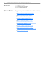
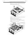
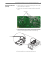
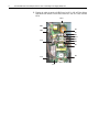
Service Bulletin
PowerFlex 400 Frame G and H Replacement
Procedure for Switching Power Supply (SPS)
Board
Contents
This publication provides instructions for replacing the switching power
supply (SPS) board for PowerFlex 400 Frame G and H drives. For
additional drive information, refer to the PowerFlex 400 User Manual,
publication 22C-UM001....
What This Kit Contains
•
•
•
•
•
Safety Precautions
The following general precautions apply to the PowerFlex 400 drive.
New SPS board
Five spare M4 screws to be used for the new SPS board
Three new steel clips to be used on power devices AD18, AQ3 and AQ4
A cable tie to be used on loose cables (for Frame H only)
This publication
!
ATTENTION: To avoid an electric shock hazard, verify that the
voltage on the bus capacitors has discharged before performing
any work on the drive. Wait five minutes for the capacitors to
discharge. Then, measure the DC bus voltage at the DC- and
DC+ terminals or at the DC- and P2 terminals on the power
terminal block. The voltage must be zero.
A darkened LCD display and LEDs are not an indication that
capacitors have discharged to safe voltage levels.
!
!
Only qualified electrical personnel familiar with the construction
and operation of this equipment and hazards involved should
install, start and/or adjust this equipment. Read and understand
these instructions in their entirety before proceeding. Failure to
observe this precaution could result in severe bodily injury or
loss of life.
ATTENTION: This drive contains ESD (Electrostatic
Discharge) sensitive parts and assemblies. Static control
precautions are required when installing, testing, servicing or
repairing this assembly. Component damage may result if ESD
control procedures are not followed. If you are not familiar with
static control procedures, reference A-B publication 8000-4.5.2,
“Guarding Against Electrostatic Damage” or any other
applicable ESD protection handbook.
5011677701-T3P1
2
PowerFlex 400 Frame G and H Replacement Procedure for Switching Power Supply (SPS) Board
What You Need
• A #1 Phillips screwdriver
• A small straight blade screwdriver
• A pair of diagonal cutting pliers
Replacement Procedure
The replacement procedure for the SPS board is described in the following
sections:
❐ Removing the Drive from the Package on page 3
❐ Removing and Locking Out Power on page 3
❐ Opening the Drive (Frame G) on page 4
❐ Checking the SPS board (Frame G) on page 6
❐ Replacing the SPS board (Frame G) on page 7
❐ Putting the Drive Back Together (Frame G) on page 11
❐ Opening the Drive (Frame H) on page 12
❐ Checking the SPS board (Frame H) on page 14
❐ Replacing the SPS board (Frame H) on page 15
❐ Putting the Drive Back Together (Frame H) on page 19
❐ Packaging the Drive on page 20
PowerFlex 400 Frame G and H Replacement Procedure for Switching Power Supply (SPS) Board
3
Removing the Drive from the If the drive is packaged, do the following.
Package
1. Cut the straps holding the box cover to the pallet of the drive.
2. Remove the box cover and foam.
3. Set aside the user manual and lifting instructions.
4. Open the plastic bag surrounding the drive.
Removing and Locking Out
Power
If the drive is in service, do the following.
1. Turn off and lock out all incoming power to the drive. Wait five minutes.
L1
L2
L3
I
O
2. Verify that there is no voltage at the input power terminals.
4
PowerFlex 400 Frame G and H Replacement Procedure for Switching Power Supply (SPS) Board
Opening the Drive (Frame G) 1. Loosen the four front cover captive screws.
2. Remove the front cover and set it aside.
!
ATTENTION: To avoid an electric shock hazard, verify that the
voltage on the bus capacitors has discharged before performing
any work on the drive. Wait five minutes for the capacitors to
discharge. Then, measure the DC bus voltage at the DC- and
DC+ terminals or at the DC- and P2 terminals on the power
terminal block. The voltage must be zero.
A darkened LCD display and LEDs are not an indication that
capacitors have discharged to safe voltage levels.
PowerFlex 400 Frame G and H Replacement Procedure for Switching Power Supply (SPS) Board
3. Remove the two screws for the clear plastic guard and set them aside.
4. Remove the plastic guard and set it aside.
5. Remove the two M5 screws for the top choke cover and set them aside.
6. Remove the choke cover and set it aside.
7. Disconnect the ribbon cable from the control board.
8. Remove the four M4 screws for the control tray and set them aside.
9. Remove the control tray and set it aside.
Choke cover
M5*P0.8
Ribbon cable
M4*P0.7
M4*P0.7
M5*P0.8
M4*P0.7
M4*P0.7
5
6
PowerFlex 400 Frame G and H Replacement Procedure for Switching Power Supply (SPS) Board
Checking the SPS board
(Frame G)
1. Locate and compare the transformers, AT3, AT4, and AT5 on the current
SPS board with the ones on the new SPS board.
Transformers,
AT3, AT4 and AT5
Capacitors, AC59
through to AC64
SPS board
Power board
The good board has larger AT3, AT4, and AT5 transformers.
Each of these transformers is labeled with a date code in the format
yyww where yy represents the year, and ww represents the week. For
example, a date code of 0801 means the transformer was dated in the
first week of the year 2008. If the transformer has a date code of 0801 or
later, it is not defective.
Date code on transformers
2. Locate and compare the capacitors, AC59 through AC64 on the current
SPS board with the ones on the new SPS board.
The good board has smaller capacitors at AC59 through AC64.
If the SPS board does not need to be replaced, skip to Putting the Drive
Back Together (Frame G) on page 11.
PowerFlex 400 Frame G and H Replacement Procedure for Switching Power Supply (SPS) Board
Replacing the SPS board
(Frame G)
1. Verify the rubber covers are properly installed on power devices AD18,
AQ3 and AQ4 on the new SPS board.
2. Verify the three nylon standoffs are properly installed on the new SPS
board.
Nylon standoffs
3. On the old SPS board, remove the three steel clips from the heatsinked
power devices AD18, AQ3 and AQ4. Pry between the clip and the heat
sink using a small straight blade screwdriver to loosen the clips.
Steel clips
4. Relax the four M4 screws on the bottom of the heat sink.
7
8
PowerFlex 400 Frame G and H Replacement Procedure for Switching Power Supply (SPS) Board
5. Unplug the cables from the old SPS board at AJ11, AJ4, AJ5, the ribbon
cable from AJ3 and the six fan cables from AJ1, AJ2, AJ7, AJ8, AJ9 and
AJ10.
AD18
AQ3
AJ2
AQ4
AJ1
AJ9
AJ10
AJ7
AJ4
AJ8
AJ3
AJ5
AJ6
AJ11
PowerFlex 400 Frame G and H Replacement Procedure for Switching Power Supply (SPS) Board
9
6. Remove the five M4 screws holding the SPS board and lift the SPS board
out of the drive.
M4*P0.7
M4*P0.7
M4*P0.7
M4*P0.7
M4*P0.7
7. Place the new SPS board where the old one was. Be careful to make sure
the black plastic insulator wraps around the edges of the SPS board and
that it is not pinched.
8. Place the five M4 screws back in to secure the SPS board.
Use a torque of about 0.9…1.1 N-m (7.8…9.6 lb.-in.).
9. Adjust the heat sink and power devices to make sure they are fully in
contact with each other with no gap in between.
10.Place the three new steel clips onto the power devices AD18, AQ3 and
AQ4. Make sure the hole on the clip is aligned with the bump on the heat
sink. Pull on the clip and make sure it will not fall off.
11.Tighten the four M4 screws on the bottom of the heat sink with a torque
of 1.4…1.6 N-m (12.2…13.9 lb.-in.).
12.Plug the ribbon cable back into AJ3.
!
ATTENTION: All the cable connectors are keyed and should
only fit the correct connector the proper way. If you find that two
connectors do not fit, do not force the connection.
10
PowerFlex 400 Frame G and H Replacement Procedure for Switching Power Supply (SPS) Board
13.Plug the three-wire cable with the ferrite bead back into AJ11.
14.Plug the two-wire cable routed from DJ2 on the power board into AJ5 on
the SPS board.
15.Plug the two-wire cable that routes from under the circuit boards to AJ4.
AJ6 is used for a ground jumper and is normally left open.
16.Plug the pair of five-wire fan cables into AJ1 and AJ2.
17.Plug a pair of three-wire fan cables into AJ8 and AJ17.
18.Plug the other pair of three-wire fan cables into AJ9 and AJ10.
AJ11 (3-pin connector)
AJ4 (2-pin connector)
AJ2 (5-pin fan connector)
AJ1 (5-pin fan connector)
AJ9 (3-pin fan connector)
AJ10 (3-pin fan connector)
AJ7 (3-pin fan connector)
AJ8 (3-pin fan connector)
AJ3 (20-pin connector)
AJ5 (2-pin connector)
19.Check that all of the cables are properly seated including the cables on
the power board that are close to the SPS board.
PowerFlex 400 Frame G and H Replacement Procedure for Switching Power Supply (SPS) Board
Putting the Drive Back
Together (Frame G)
11
1. Place the control tray over the circuit boards and plug the ribbon cable
back into the control board.
In order for the control tray to seat properly, the large ferrite on the
ribbon cable needs to be routed to the right of transformer ET9 on the
power board. The control ribbon cable slack should be pushed down
inside the drive.
2. With a torque of 1.4…1.6 N-m (12.2…13.9 lb.-in.), install the four M4
screws back in to secure the control tray.
3. Place the choke cover over the choke at the top of the drive.
4. With a torque of 2.5…2.9 N-m (21.7…26.0 lb.-in.), install the two M5
screws back in to secure the choke cover.
5. Install the clear plastic guard over the loosened M4 screws by the
terminal block. Torque the screws to about 1.2…1.4 N-m (10.4…12.2
lb.-in.).
6. Install the front cover and torque the four captive screws to about
1.3…1.5 N-m (11.3…13.0 lb.-in.).
Proceed to Packaging the Drive on page 20 if you need to package the drive.
12
PowerFlex 400 Frame G and H Replacement Procedure for Switching Power Supply (SPS) Board
Opening the Drive (Frame H) 1. Loosen the four front cover captive screws.
2. Remove the front cover and set it aside.
!
ATTENTION: To avoid an electric shock hazard, verify that the
voltage on the bus capacitors has discharged before performing
any work on the drive. Wait five minutes for the capacitors to
discharge. Then, measure the DC bus voltage at the DC- and
DC+ terminals or at the DC- and P2 terminals on the power
terminal block. The voltage must be zero.
A darkened LCD display and LEDs are not an indication that
capacitors have discharged to safe voltage levels.
3. Remove the six captive screws for the top choke cover.
4. Remove the choke cover and set it aside.
Choke cover
Front cover
PowerFlex 400 Frame G and H Replacement Procedure for Switching Power Supply (SPS) Board
5. Remove the four M4 screws for the clear plastic guard.
6. Remove the plastic guard and set it aside.
7. Disconnect the ribbon cable from the control board.
8. Remove the three M4 and two M5 screws for the control tray and set
them aside.
9. Remove the control tray and set it aside.
M4*P0.7
Ribbon cable
M5*P0.8
M4*P0.7
Control tray
M4*P0.7
M4*P0.7
Plastic
guard
M5*P0.8
M4*P0.7
M4*P0.7
M4*P0.7
13
14
PowerFlex 400 Frame G and H Replacement Procedure for Switching Power Supply (SPS) Board
Checking the SPS board
(Frame H)
1. Locate and compare the transformers, AT3, AT4, and AT5 on the current
SPS board with the ones on the new SPS board.
Transformers,
AT3, AT4 and AT5
Cable tie
Capacitors, AC59
through to AC64
SPS board
Power board
The good board has larger AT3, AT4, and AT5 transformers.
Each of these transformers is labeled with a date code in the format
yyww where yy represents the year, and ww represents the week. For
example, a date code of 0801 means the transformer was dated in the
first week of the year 2008. If the transformer has a date code of 0801 or
later, it is not defective.
Date code on transformers
2. Locate and compare the capacitors, AC59 through AC64 on the current
SPS board with the ones on the new SPS board.
The good board has smaller capacitors at AC59 through AC64.
If the SPS board does not need to be replaced, skip to Putting the Drive
Back Together (Frame H) on page 19.
PowerFlex 400 Frame G and H Replacement Procedure for Switching Power Supply (SPS) Board
Replacing the SPS board
(Frame H)
15
1. Verify the rubber covers are properly installed on power devices AD18,
AQ3 and AQ4 on the new SPS board.
2. Verify the three nylon standoffs are properly installed on the new SPS
board.
Nylon standoffs
3. On the old SPS board, remove the three clips from the heatsinked power
devices AD18, AQ3 and AQ4. Pry between the clip and the heatsink
using a small straight blade screwdriver to loosen the clips.
Remove clips
16
PowerFlex 400 Frame G and H Replacement Procedure for Switching Power Supply (SPS) Board
4. Relax the four M5 screws on the bottom of the heat sink.
5. Unplug the cables from the old SPS board at AJ11, AJ4, AJ5, the ribbon cable
from AJ3 and the six fan cables from AJ1, AJ2, AJ7, AJ8, AJ9 and AJ10.
6. Cut the cable tie by using a pair of diagonal cutting pliers.
AD18
AQ3
AJ2
AQ4
AJ1
AJ9
AJ10
AJ7
AJ4
AJ8
AJ3
Cable tie
AJ5
AJ6
AJ11
PowerFlex 400 Frame G and H Replacement Procedure for Switching Power Supply (SPS) Board
17
7. Remove the five M4 screws holding the SPS board and lift the SPS board
out of the drive.
8. Place the new SPS board where the old one was.
9. Place the five M4 screws back in to secure the SPS board.
Use a torque of about 1.2…1.8 N-m (10.4…12.2 lb.-in.).
10.Adjust the heat sink and power devices to make sure they are fully in
contact with each other with no gap in between.
11.Place the three new steel clips onto the power devices AD18, AQ3 and
AQ4. Make sure the hole on the clip is aligned with the bump on the heat
sink. Pull on the clip and make sure it will not fall off.
12.Tighten the four M5 screws on the bottom of the heat sink with a torque
of 2.5…2.9 N-m (21.7…26.0 lb.-in.).
18
PowerFlex 400 Frame G and H Replacement Procedure for Switching Power Supply (SPS) Board
13.Plug the ribbon cable back into AJ3.
!
ATTENTION: All the cable connectors are keyed and should
only fit the correct connector the proper way. If you find that two
connectors do not fit, do not force the connection.
14.Plug the three-wire cable back into AJ11 and secure the cable with a
cable tie.
15.Plug the two-wire cable routed from DJ2 on the power board into AJ5 on
the SPS board.
16.Plug the two-wire cable that routes from under the circuit boards to AJ4.
AJ6 is used for a ground jumper and is normally left open.
17.Plug the pair of five-wire fan cables into AJ1 and AJ2.
18.Plug a pair of three-wire fan cables into AJ8 and AJ17.
19.Plug the other pair of three-wire fan cables into AJ9 and AJ10.
AJ4 (2-pin connector)
AJ2 (5-pin fan connector)
AJ1 (5-pin fan connector)
AJ9 (3-pin fan connector)
AJ10 (3-pin fan connector)
AJ7 (3-pin fan connector)
AJ8 (3-pin fan connector)
AJ3 (20-pin connector)
AJ5 (2-pin connector)
AJ11 (3-pin connector)
Cable tie
20.Check that all of the cables are properly seated including the cables on
the power board that are close to the SPS board.
PowerFlex 400 Frame G and H Replacement Procedure for Switching Power Supply (SPS) Board
Putting the Drive Back
Together (Frame H)
19
1. Place the control tray over the circuit boards and plug the ribbon cable
back into the control board. The ribbon cable needs to go through a hole
in the control tray. The control ribbon cable slack should be pushed down
inside the drive.
2. Install the three shorter M4 screws with a torque of 1.4…1.6 N-m
(12.2…13.9 lb.-in.) and two M5 screws with a torque of 2.5…2.9 N-m
(21.7…26.0 lb.-in.) back in to secure the control tray.
3. Place the plastic guard over the terminal block and install the four
longer M4 screws. Torque the screws to about 1.2…1.4 N-m
(10.4…12.2 lb.-in.).
4. Place the choke cover over the choke at the top of the drive.
5. Tighten the six captive screws with a torque of 1.2…1.4 N-m
(10.4…12.2 lb.-in.) to secure the choke cover.
6. Install the front cover and torque the four captive screws to about
1.2…1.8 N-m (10.4…12.2 lb.-in.).
Proceed to Packaging the Drive on page 20 if you need to package the drive.
Packaging the Drive
If the drive is to be packaged, do the following:
1. Wrap the plastic bag around the drive and secure with tape.
2. Place the user manual and lifting instructions back on top of the drive.
3. Place the foam and box cover back on the drive.
4. Strap the box cover to the pallet of the drive.
www.rockwellautomation.com
Power, Control and Information Solutions
Americas: Rockwell Automation, 1201 South Second Street, Milwaukee, WI 53204-2496 USA, Tel: (1) 414.382.2000, Fax: (1) 414.382.4444
Europe/Middle East/Africa: Rockwell Automation SA/NV,Vorstlaan/Boulevard du Souverain 36, 1170 Brussels, Belgium, Tel: (32) 2 663 0600, Fax: (32) 2 663 0640
Asia Pacific: Rockwell Automation, Level 14, Core F,Cyberport 3, 100 Cyberport Road, Hong Kong, Tel: (852) 2887 4788, Fax: (852) 2508 1846
Publication 22C-SB001B-EN-P – June 2008
Copyright © 2008 Rockwell Automation. All rights reserved. Printed in Taiwan.