1
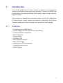
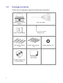
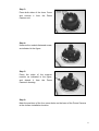
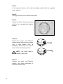
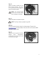
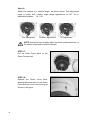
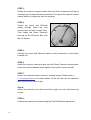
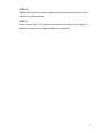
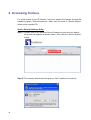
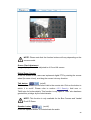
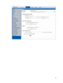
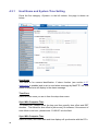
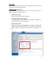
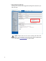
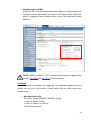
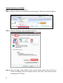
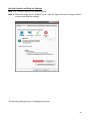
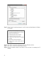
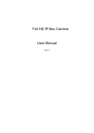
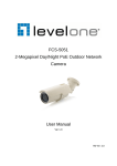
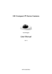
FCS-3081
H.264 2-Megapixel PoE Vandal Dome Camera
User Manual
Ver1.3
Table of Contents
1.
2.
Introduction.................................................................................................................3
1.1
Features ...................................................................................................................... 3
1.2
Package Contents ....................................................................................................... 4
1.3
Camera Overview ........................................................................................................ 5
1.4
Camera’s Connectors................................................................................................ 6
Preparations for IP Camera Setup ............................................................................7
2.1
System Requirements ................................................................................................. 7
2.2
Installation ................................................................................................................... 7
5.1
Power and Ethernet Cable Connection ........................................................................ 7
5.2
Hard Ceiling................................................................................................................. 8
5.3
4S Mount Electrical Box............................................................................................. 13
3. Accessing Camera.......................................................................................................16
Using recording software....................................................................................................... 20
Installing DC Viewer Software Online.................................................................................... 21
4.
Configuration & Operation.......................................................................................23
4.1
Browser-based Viewer Introduction ........................................................................... 23
4.2
Home Page................................................................................................................ 24
4.3
System Related Settings............................................................................................ 26
4.4
4.3.1
Host Name and System Time Setting......................................................... 28
4.3.2
Security ...................................................................................................... 29
4.3.3
Network...................................................................................................... 32
4.3.4
DDNS......................................................................................................... 37
4.3.5
Mail ............................................................................................................ 38
4.3.6
FTP ............................................................................................................ 39
4.3.7
Application (Excluding Compact IP Dome) ................................................. 40
4.3.8
Motion Detection ........................................................................................ 45
4.3.9
Storage Management................................................................................. 49
4.3.10
Recording................................................................................................... 51
4.3.11
File Location............................................................................................... 52
4.3.12
Iris Adjustment (Excluding Compact IP Dome) ........................................... 53
4.3.13
View Log File.............................................................................................. 54
4.3.14
View User Information ................................................................................ 55
4.3.15
View Parameters........................................................................................ 57
4.3.16
Factory Default........................................................................................... 58
4.3.17
Software Version........................................................................................ 59
4.3.18
Software Upgrade ...................................................................................... 60
4.3.19
Maintenance............................................................................................... 63
Video and Audio Streaming Settings ......................................................................... 64
1
4.5
4.6
4.4.1
Video Resolution and Rotate Type ............................................................. 64
4.4.2
Video Compression .................................................................................... 67
4.4.3
Video OCX Protocol ................................................................................... 69
4.4.4
Video Frame Skip....................................................................................... 70
4.4.5
Video Mask............................................................................................... 71
4.4.6
Audio Mode and Bit Rate Settings.............................................................. 72
Camera Settings........................................................................................................ 74
4.5.1
Exposure Setting ........................................................................................ 75
4.5.2
White Balance Setting ................................................................................ 76
4.5.3
Brightness Setting ...................................................................................... 77
4.5.4
Sharpness Setting ...................................................................................... 77
4.5.5
Contrast Setting ......................................................................................... 77
4.5.6
Saturation Setting....................................................................................... 77
4.5.7
Hue Setting ................................................................................................ 78
4.5.8
IR Function................................................................................................. 78
4.5.9
TV System Setup ....................................................................................... 78
Logout ....................................................................................................................... 79
Appendix A: Technical Specifications ...........................................................................80
Appendix B: Internet Security Settings .........................................................................81
Appendix C: DC Viewer Download Procedure ..............................................................85
Appendix D: Install UPnP Components .........................................................................87
Default ID / Password
Login ID
root
2
Password
1.
Introduction
The Full HD Vandal Proof IP Dome Camera is capable of serving real-time
streaming and makes image quality more smoothly. In addition to MJPEG real
time streaming, this camera develops H.264 codec to apply for high resolution
digital broadcast.
With compact and sophisticated mechanical design, the Full HD Vandal Proof
IP Dome Camera is easy installed and aesthetic. Additionally, the IP Dome
Camera’s vandal proof cover can protect the camera from heavy damage.
1.1
Features
• Progressive Scan CMOS Sensor
• Full HD 1080p / HD 720p real-time at dual streaming
• H.264 and MJPEG compression
• Motion Detection
• Privacy Masks
•
•
•
•
Day/Night (ICR)
Micro SD/SDHC support
BNC analog output
Weatherproof (IP66 international)
• Vandal proof dome cover
• ONVIF Support
3
1.2
Package Contents
Please check the package contains the following items listed below.
Vandal Proof IP Dome
All-in-One cable
Camera
Power Terminal Block
Self Tapping Screws
Plastic Screw Anchors
(×4)
(×4)
CD
Quick Guide
(bundled software and
documentation)
4
Security Torx
Rubber Washers (×6)
1.3
Camera Overview
Top View
Side View
5
1.4
Camera’s Connectors
The diagram below shows the IP Dome Camera’s reset button and various
connectors. Definition for each connector will be given as follows.
Connector
Remarks
-
Restore to factory default
BNC
-
Analog Video Output
1
Output+
2
Output-
3
Input+
4
Input-
1
Input
2
GND
3
Output (R)
4
Output (L)
1
Power
2
Reserved
3
GND
1
Power-1
2
Earth GND
3
Power-2
-
10/100 Mbps Ethernet / PoE
Audio I/O
DC 12V
Power
AC 24V
RJ-45
6
Definition
Reset Button
Alarm I/O
e
Pin No.
Alarm connection
Two-way audio transmission
Power connection
2.
Preparations for IP Camera Setup
This chapter provides information about system requirements for IP Camera
operation, power connection, Ethernet connection and ways to access to the
camera.
2.1
System Requirements
To perform the IP Camera via web browser, please ensure your PC is in good
network connection, and meet system requirements as described below.
Items
System Requirement
1. Intel○R Pentium○R M, 2.16 GHz or Intel○R CoreTM2 Duo,
Personal Computer
2.0 GHz
2. 2 GB RAM or more
2.2
Operating System
Windows VISTA or Windows XP
Web Browser
Microsoft Internet Explorer 6.0 or later
Network Card
10Base-T (10 Mbps) or 100Base-TX (100 Mbps) operation
Viewer
ActiveX control plug-in for Microsoft IE
Installation
Please read the instructions provided in this chapter thoroughly before installing
the Full HD Multi-Res Vandal Proof IP Dome Camera.
2.3
Power and Ethernet Cable Connection
Power Connection
Make sure the camera’s power cable is correctly and firmly connected; refer to
the pin definition table in section 2.2 Camera’s Connectors. If using Power over
Ethernet (PoE), make sure Power Sourcing Equipment (PSE) is in use in the
network.
Ethernet Cable Connection
Use of Category 5 Ethernet cable is recommended for network connection; to
have best transmission quality, cable length shall not exceed 100 meters.
Connect one end of the Ethernet cable to the RJ-45 connector of the IP Dome
Camera, and the other end of the cable to the network switch or PC.
7
NOTE: In some cases, you may need use an Ethernet crossover cable
when connecting the IP Dome Camera directly to the PC.
Check the status of the link indicator and activity indicator LEDs; if the LEDs are
unlit, please check LAN connection.
Green Link Light indicates good network connection.
Orange Activity Light flashes for network activity indication.
NETWORK
2.4
Hard Ceiling
The Vandal Proof IP Dome Camera can be installed directly on a wall or ceiling.
Please note that the wall or ceiling must have enough strength to support the IP
Dome Camera.
Follow the steps below to install the IP Dome Camera:
Step 1:
Unpack the Vandal Proof IP Dome Camera package and take out the IP
Dome Camera.
Step 2:
Use the supplied Security Torx to
unscrew the two Torx screws on the
side of the Dome Cover, as shown in
the figure, and open the Dome
Cover.
8
Step 3:
Press both sides of the Inner Cover
and remove
Camera unit.
it
from
the
Dome
Step 4:
Unscrew the module-fastened screw,
as indicated in the figure.
Step 5:
Press the sides of the snap-on
module, as indicated in the figure,
and detach it from the Dome
Camera’s housing.
Step 6:
Mark the positions of the four screw holes on the base of the Dome Camera
at the chosen installation location.
9
Step 7:
In the marked locations, drill each hole slightly smaller than the supplied
screw anchors.
Step 8:
Put supplied anchors into these drilled holes.
Step 9:
Fasten the Dome Camera’s housing
with the four equipped self tapping
screws.
Step 10:
Thread the power and Ethernet
cables through either the side conduit
entry or back conduit entry, as
illustrated. Users may use a coin to
screw off the conduit entry block.
NOTE: The Power Cable is
omitted if using PoE.
Step 11:
Connect the power and Ethernet
cables to the mating connectors on
the Dome Camera unit.
10
Step 12:
Attach the snap-on module into the
Dome Camera housing, and screw
the module-fastened screw tightly to
secure the camera module.
NOTE: The terminal blocks
should face the side conduit
entry, as shown in the figure.
Step 13:
Connect the power and network outputs.
NOTE: The Power Cable is omitted if using PoE.
STEP 14:
Access the camera browser-viewer for viewing images. Please refer to
Accessing Camera for further details. Users can also use the camera’s BNC
connector for video output.
Step 15:
Adjust the zoom ring screw to set the
desired
zoom;
subsequently,
modifying the focus ring screw to set
the desired focal length.
11
Step 16:
Adjust the camera to a desired angle, as shown below. Pan adjustment
range is nearly 360°; rotation angle range approach es to 270°. Tilt is
adjustable between ﹣10° ~ 90°.
Pan Adjustment
Rotation Adjustment
Tilt Adjustment
NOTE: Adjust the lens carefully within the limits mentioned above, or
the cables underneath would be harmed.
STEP 17:
Put the Inner Cover back to the
Dome Camera unit.
STEP 18:
Replace the Dome Cover back,
aligning the arrow mark on the Dome
Cover with the one on the housing as
shown in the figure.
12
STEP 19:
Screw on the two Torx screws on the
side of the Dome Cover tightly to
fasten the Dome Cover. Camera
installation is complete.
2.5
4S Mount Electrical Box
Before installing the IP Dome Camera in the 4S Electrical Box, please unscrew
and open the Dome Cover with the Security Torx.
Figure: 4S Mount Electrical Box
STEP 1:
Run the wires (Ethernet and power) through the wall.
NOTE: The power cable is omitted if using PoE.
STEP 2:
Disassemble the Dome Camera’s Inner Cover (see the illustration in 5.2
Hard Ceiling: Step 3) from the Dome Camera unit.
13
STEP 3:
Detach the snap-on camera module from the Dome Camera’s housing by
unscrewing the module-fastened screw first. Then press the sides of camera
module and pull it slightly up from the housing.
STEP 4:
Thread the power and Ethernet
cables through either the side
conduit entry or back conduit entry.
Then fasten the Dome Camera’s
housing on the Electrical Box with
the two screws.
STEP 5:
Connect the power and Ethernet cables to their connectors on the Dome
Camera unit.
STEP 6:
Attach the snap-on camera module onto the Dome Camera’s housing and.
screw the module-fastened screw tightly to secure the camera module.
STEP 7:
Access the camera browser-viewer for viewing images. Please refer to
6. Accessing Camera for further details. Users can also use the camera’s
BNC connector for video output.
Step 8:
Adjust the camera's zoom level and focal length via zoom and focus ring
screws.
STEP 9:
Position the camera at a desired angle by Pan/Tilt/Rotation adjustment.
14
STEP 10:
Replace the Dome Cover back, aligning the arrow mark on the Dome Cover
with the one on the housing.
STEP 11:
Screw on the two Torx screws on the side of the Dome Cover tightly to
fasten the Dome Cover. Camera installation is complete.
15
3. Accessing Camera
For initial access to the IP Camera, users can search the camera through the
installer program: DeviceSearch.exe, which can be found in “Device Search”
folder in the supplied CD.
Device Search Software Setup
Step 1: Double click on the program Device Search.exe (see the icon below);
its window will appear as shown below. Then click the “Device Search”
button.
Step 2: The security alert window will pop up. Click “Unblock” to continue.
16
Device Search
Step 3: Click “Device Search” again, and all the finding IP devices will be listed
in the page, as shown in the figure below. The IP Camera’s default
IP address is: 192.168.0.250.
Step 4: Double click or right click and select “Browse” to access the camera
directly via web browser.
Step 5: Then the prompt window of request for entering default username
and password (as shown below) will appear for logging in to the IP
Camera.
17
The default login ID and password are:
Login ID
Password
root
NOTE: ID and password are case sensitive.
NOTE: It is strongly advised that administrator’s password be
altered for the security concerns. Refer to section 5.3.2 Security
for further details.
Additionally, users can change the IP Camera’s network property, either DHCP
or Static IP, directly in the device finding list. Refer to the following section for
changing the IP Camera’s network property.
Example of Changing IP Camera’s Network Property
Users can directly change an IP Camera’s network property, ex. from static IP
to DHCP, in the finding device list. The way to change the IP Camera’s network
property is specified below:
Step 1: In the finding device list, click on the IP Camera that you would like to
change its network property. On the selected item, right click and select
“Network Setup.” Meanwhile, record the IP Camera’s MAC address, for
future identification.
Step 2: The “Network Setup” page will come out. Select “DHCP,” and press
“Apply” button down the page.
18
Step 3: Click “OK” on the Note of setting change. Wait for one minute to
re-search the IP Camera.
Step 4: Click the “Device Search” button to search all the devices. Then select
the IP Camera with the correct MAC address. Double click on the IP
Camera, and the login window will come out.
Step 5: Enter User name and Password to access the IP Camera.
19
Using recording software
The product software CD also contains recording software-IP CamSecure, allowing
simultaneous monitoring and video recording for multiple Network Cameras. Please install
the recording software; then launch the program to add the Network Camera to the
Channel list. For detailed information about how to use IP CamSecure, please refer to the
user’s manual of the software or download it at http://global.level1.com.
20
Installing DC Viewer Software Online
For the initial access to the IP Camera, a client program, DC Viewer, will be
automatically installed to your PC when connecting to the IP Camera.
If the Web browser doesn’t allow DC Viewer installation, please check the
Internet security settings or ActiveX controls and plug-ins settings (see
Appendix B: Internet Security Settings) to continue the process.
The Information Bar (just below the URL bar) may come out and ask for
permission to install the ActiveX Control for displaying video in browser (see the
figure below). Right click on the Information Bar and select “Install ActiveX
Control…” to allow the installation.
Then the security warning window will pop up. Click “Install” to carry on software
installation.
Click “Finish” to close the DC Viewer window when download is finished. For
the detailed software download procedure, please refer to Appendix C: DC
Viewer Download Procedure.
21
Once login to the IP Camera, users will see the Home page as shown below:
NOTE: The “talk” button below the screen only displays in Box Camera
and Vandal Proof IP Dome.
Administrator/User Privileges
“Administrator” represents the person who can configure the IP Camera and
authorize users access to the camera; “User” refers to whoever has access to
the camera with limited authority, i.e. entering Home and Camera setting pages.
Image and Focus Adjustment
The image displays on the Home page when successfully accessing to the IP
Camera. Adjust zoom and focus as necessary to produce a clear image.
22
4.
Configuration & Operation
The IP Camera is provided with a user-friendly browser-based configuration
interface, and a free bundled IP CamSecure Lite for record and playback video.
In this chapter, information about main page introduction, system related
settings and camera settings will be described in detail.
For further information about IP CamSecure, please refer to IP CamSecure user
manual.
4.1
Browser-based Viewer Introduction
The figure below shows the Home page of the IP Camera’s viewer window.
Time Display
Live Video Panel
Recording Button
Display Mode
Video Compression Info
Video Stream Pause Button
Snapshot Button
Speaker Button
Talk Button
NOTE: Only the Box Camera and Vandal Proof IP Dome support the
“Talk” function.
There are five tabs: Home, System, Streaming, Camera and Logout on the top
panel.
Home
Users can monitor live video of the targeted area.
23
System setting
The administrator can set host name, system time, root password, network
related settings, etc. Further details will be interpreted in section 4.3 System
Related Settings.
Streaming setting
The administrator can modify video resolution and rotate type and select audio
compression mode in this page.
Camera setting
Users can adjust various camera parameters, including <Exposure>, <White
Balance>, <Brightness>, <Sharpness>, <Contrast> and <Digital Zoom>.
Logout
Click on the tab to re-login the IP Camera with another username and
password.
4.2
Home Page
In the Home page, there are several function buttons right down the displayed
image.
24
NOTE: Please note that the function buttons will vary depending on the
camera model.
Screen Size Adjustment
Image display size can be adjusted to x1/2 and full screen.
Digital Zoom Control
In the full screen mode, users can implement digital PTZ by rotating the mouse
wheel (for zoom in/out), and drag the mouse into any direction.
(on/off)
Talk button
Talk function allows the local site to talk to the remote site. Click on the button to
switch it to on/off. Please refer to section 4.3.2 Security: Add user >>
Talk/Listen for further details. This function is only open to “User” who has been
granted this privilege by the Administrator.
NOTE: This function is only available for the Box Camera and Vandal
Proof IP Dome.
(on/off)
Speaker button
Press the Speaker button to mute/activate the audio.
25
Snapshot button
Press the button, and the JPEG snapshots will automatically be saved in the
appointed place. The default place of saving snapshots is: C:\. To change the
storage location, please refer to section 5.3.11 File Location for further details.
(pause/restart)
Video Streaming Pause /Restart button
Press the stop button to disable video streaming, the live video will be displayed
as black. Press the restart button to show the live video again.
(on/off)
Recording button
Press the button and the recordings from the Live View will be saved to the
location specified in the “File Location” (snapshot) page; see section 4.3.11 File
Location for further details.
4.3
System Related Settings
The figure below shows all categories under the “System” tab. Each category in
the left column will be explained in the following sections.
NOTE: The “System” configuration page is only accessible by the
Administrator.
26
27
4.3.1
Host Name and System Time Setting
Press the first category: <System> in the left column; the page is shown as
below.
Host Name
The name is for camera identification. If alarm function (see section 4.3.7
Application is enabled and is set to send alarm message by Mail/FTP, the host
name entered here will display in the alarm message.
Time Zone
Select the time zone you are in from the drop-down menu.
Sync With Computer Time
To enable DST, please check the item and then specify time offset and DST
duration. The format for time offset is [hh:mm:ss]; for instance, if the amount of
time offset is one hour, please enter “01:00:00” into the field.
Sync With Computer Time
Select the item, and video date and time display will synchronize with the PC’s.
28
Manual
The Administrator can set video date, time and day manually. Entry format
should be identical with that shown next to the enter fields.
Sync with NTP server
Network Time Protocol (NTP) is an alternate way to synchronize your camera’s
clock with a NTP server. Please specify the server you wish to synchronize in
the enter field. Then select an update interval from the drop-down menu. For
further information about NTP, please see the web site: www.ntp.org.
4.3.2
Security
Click the category: <Security>, and the page is shown as the figure below.
Root password
Change the administrator’s password by inputting the new password in both text
boxes. The input characters/numbers will be displayed as dots for security
purposes. After clicking <Save>, the web browser will ask the Administrator for
the new password for access. The maximum length of the password is 14 digits.
29
NOTE: The following characters are valid: A-Z, a-z, 0-9, !#$%&’-.@^_~.
Add user
Type the new user's name and password and click <Add> to add the new user.
Both user name and password can be up to 16 characters. The new user will be
displayed in the user name list. There is a maximum of twenty user accounts.
Each user can be assigned the privileges of “Camera control”, “Talk” and
“Listen”.
•
I/O access
This item supports fundamental functions that enable users to view
video when accessing to the camera.
•
Camera control
This item allows the appointed User to change camera parameters on
the Camera Setting page.
•
Talk/Listen
Talk and Listen functions allow the appointed user in the local site (PC
site) communicating with, for instance, the administrator in the remote
site.
NOTE: The Compact IP Dome does not have Talk function.
Manage User
Delete user
To delete a user, pull down the user list, and select the user name you wish to
delete. Then click <Delete> to remove it.
Edit user
Pull down the user list and select a user name. Click <Edit> to edit the user’s
password and privilege.
NOTE: It is required to enter the User password as well as select the
function open to the user. When finished, click <Save> to modify the
account authority.
30
31
4.3.3
Network
Click <Network> in the left column, and the page will display as shown below.
Users can choose to connect to the IP Camera with fixed or dynamic (DHCP) IP
address. The IP Camera also provides PPPoE support for users who connect to
the network via PPP over Ethernet (PPPoE).
Get IP address automatically (DHCP)
The camera’s default setting is “Use fixed IP address”. Please refer to the
previous section 4. Accessing Camera for login with the default IP address.
If select “Get IP address automatically”, after the IP Camera restarts, users
can search it through the installer program: DeviceSearch.exe, which can be
found in “DeviceSearch” folder in the supplied CD.
NOTE: Please make the record of the IP Camera’s MAC address, which
can be found in the label of the camera, for identification in the future.
32
Use fixed IP address
To setup static IP address, select “Use fixed IP address” and move the cursor
to the IP address blank (as indicated below) and insert the new IP address, ex.
192.168.7.123; then go to the Default gateway (explained latter) blank and
change the setting, ex. 192.168.7.254. Press “Save” to confirm the new setting.
When using static IP address to login to the IP Camera, users can access it
either through “DeviceSearch” software (see 4. Accessing Camera) or input the
IP address in the URL bar and press “Enter”.
•
IP address
This is necessary for network identification.
•
Subnet mask
It is used to determine if the destination is in the same subnet. The
default value is “255.255.255.0”.
33
•
Default gateway
This is the gateway used to forward frames to destinations in different
subnet. Invalid gateway setting will fail the transmission to destinations
in different subnet.
•
Primary DNS
Primary DNS is the primary domain name server that translates
hostnames into IP addresses.
•
Secondary DNS
Secondary DNS is a secondary domain name server that backups the
primary DNS.
Use PPPoE
For the PPPoE users, enter the PPPoE Username and Password into the fields,
and click on the “Save” button to complete the setting.
Advanced
•
Web Server port
The default web server port is 80. Once the port is changed, the user
must be notified the change for the connection to be successful. For
instance, when the Administrator changes the HTTP port of the IP
Camera whose IP address is 192.168.0.100 from 80 to 8080, the user
must type in the web browser “http://192.168.0.100:8080” instead of
http://192.168.0.100
•
RTSP port
RTSP port could be set from 1 to 65535. (Normal Setting Port: 554,
1024 ~65535)
•
MJPEG over HTTP port
The default setting of HTTP Port is 8008; setting range: 1024 ~65535.
NOTE: Be aware to choose the different port from the one set for the
web server port.
34
UPnP Setting
• Enable UPnP
When the UPnP is enable, whenever the IP Camera is presented to the LAN,
the icon of the connected IP Cameras will appear in My Network Places to
allow for direct access as shown below.
FCS-1131
FCS-1131
FCS-1141
FCS-3071
35
NOTE: To enable this function, please make sure the UPnP
component is installed on your computer. Please refer to
Appendix D: Install UPnP components for UPnP component
installation procedure.
• Enable UPnP port forwarding
When the UPnP port forwarding is enabled, the IP Camera is allowed to
open the web server port on the router automatically.
NOTE: To enable this function, please make sure that your router
supports UPnP and it is activated
•
Friendly name
Set the name for the IP Camera for identity.
36
4.3.4
DDNS
Dynamic Domain Name System (DDNS) allows a host name to be constantly
synchronized with a dynamic IP address. In other words, it allows those using a
dynamic IP address to be associated to a static domain name so others can
connect to it by name.
Enable DDNS
Check the item to enable DDNS.
Provider
Select one DDNS host from the provider list.
Host name
Enter the registered domain name in the field.
Username/E-mail
Enter the username or e-mail required by the DDNS provider for authentication.
37
Password/Key
Enter the password or key required by the DDNS provider for authentication.
4.3.5
Mail
The Administrator can send an e-mail via Simple Mail Transfer Protocol (SMTP)
when motion is detected. SMTP is a protocol for sending e-mail messages
between servers. SMTP is a relatively simple, text-based protocol, where one or
more recipients of a message are specified and the message text is transferred.
The configuration page is shown as follows:
Two sets of SMTP can be configured. Each set includes SMTP Server, Account
Name, Password and E-mail Address settings. For SMTP server, contact your
network service provider for more specific information.
38
4.3.6
FTP
The Administrator can set as sending alarm message to a specific File Transfer
Protocol (FTP) site when motion is detected. Users can assign alarm message
to up to two FTP sites. The FTP setting page is shown below. Enter the FTP
details, which include server, server port, user name, password and remote
folder, in the fields. Press “Save” when finished.
39
4.3.7
Application (Excluding Compact IP Dome)
The IP Camera (Box Camera and Vandal Proof Dome) equips one alarm input
and one relay output for cooperating with alarm system to catch events’ images.
Refer to alarm pin definition below to connect alarm devices to the IP Camera if
needed. The alarm configuration page is also shown below.
Alarm Pin Definition
1.
Output+
2.
3.
4.
OutputInput+
Input-
Alarm Switch
The Administrator can enable or disable the alarm function.
Alarm Type
Select an alarm type, “Normal close” or “Normal open,” that corresponds with
the alarm application.
40
Alarm Output
Define alarm output signal “high” or “low” as the normal alarm output status
according to the current alarm application.
Triggered Action (Multi-option)
The Administrator can specify alarm actions that will take when the alarm is
triggered. All options are listed as follows:
• Enable Alarm Output
Select the item to enable alarm relay output.
• Send Alarm Message by FTP/E-Mail
The Administrator can select whether to send an alarm message by FTP
and/or E-Mail when an alarm is triggered.
• Upload Image by FTP
Select this item, and the Administrator can assign a FTP site and
configure various parameters as shown in the figure below. When the
alarm is triggered, event images will be uploaded to the appointed FTP
site.
41
• Record Stream to SD Card
Select the item, and the alarm-triggered recording will be saved into your
Micro SD card.
NOTE: Please make sure the local recording (with Micro SD/
SDHC card) is activated so that this function can be implemented.
See section 4.3.10 Recording for further details.
42
• Upload Image by E-Mail
Select this item, and the Administrator can assign an e-mail address and
configure various parameters as shown in the figure below. When the
alarm is triggered, event images will be sent to the appointed e-mail
address.
NOTE: Make sure SMTP or FTP configuration has been completed. See
section 4.3.5 Mail and 4.3.6 FTP for further details.
File Name
Enter a file name in the blank, ex. image.jpg. The uploaded image’s file name
format can be set in this section. Please select the one that meets your
requirements.
•
Add date/time suffix
File name: imageYYMMDD_HHNNSS_XX.jpg
Y: Year, M: Month, D: Day
H: Hour, N: Minute, S: Second
X: Sequence Number
43
•
Add sequence number suffix (no maximum value)
File name: imageXXXXXXX.jpg
X: Sequence Number
•
Add sequence number suffix (limited value)
File Name: imageXX.jpg
X: Sequence Number
The file name suffix will end at the number being set. For example, if the
setting is up to “10,” the file name will start from 00, end at 10, and then
start all over again.
•
Overwrite
The original image in the FTP site will be overwritten by the new
uploaded file with a static filename.
Save
After complete all the settings mentions above, please click on the Save button
to save all the settings in this page.
44
4.3.8
Motion Detection
Motion Detection function allows detecting suspicious motion and triggering
alarms when motion volume in the detected area reaches/exceeds the
determined sensitivity threshold value.
In the Motion Detection setting page, there is a frame (Motion Detection
Window) displayed on the Live View Pane. The Motion Detection Window is for
defining the motion detection area. To change the size of the Motion Detection
Window, move the mouse cursor to the edge of the frame and draw it
outward/inward. Moving the mouse to the center of the frame can shift the frame
to the intended location.
Up 10 Motion Detection Windows can be set. Press the “add” button under the
Live View Pane to add a Motion Detection Window. To cancel a Motion
Detection Window, move the mouse cursor to the selected Window, and click
on the “delete” button.
45
If Motion Detection function is activated, the pop-off window (Motion) with
indication of motion will be shown.
When motion is detected, the signals will be displayed on the Motion window as
shown below.
Detailed settings of Motion Detection are described as follows:
Motion Detection
You will be able to turn on/off Motion Detection in System section. Default
setting is Off.
Motion Detection Setting
Users could adjust various parameters of Motion Detection in this section.
46
•
Sampling pixel interval [1-100]:
The default value is 10, which means system will take one sampling
pixel for every 10 pixel.
•
Detection level [1-100]:
The default level is 10. The item is to set detection level for each
sampling pixel; the smaller the value, the more sensitive it is.
•
Sensitivity level [1-100]:
The default level is 80, which means if 20% or more sampling pixels are
detected differently, system will detect motion. The bigger the value, the
more sensitive it is. Meanwhile, when the value is bigger, the red
horizontal line in the motion indication window will be lower accordingly.
•
Time interval (sec) [0-7200]:
The default interval is 10. The value is the interval between each
detected motion.
Triggered Action (Multi-option)
The Administrator can specify alarm actions that will take when motion is
detected. All options are listed as follows:
•
Enable Alarm Output
Check the item and select the predefined type of alarm output to enable
alarm relay output when motion is detected.
NOTE: This option is excluded in the Compact IP Dome
Camera.
•
Record stream to SD Card
Select this item, and the Motion Detection recording will be stored in
Micro SD/ SDHC card when motion is detected.
NOTE: Please make sure the local recording (with Micro SD/
SDHC card) is activated so that this function can be implemplemented. See section 4.3.10 Recording for further details.
•
Send Alarm Message by FTP/E-Mail
The Administrator can select whether to send an alarm message by
FTP and/or E-Mail when motion is detected.
•
Upload Image by FTP
Select this item, and the Administrator can assign a FTP site and
configure various parameters as shown in the figure below. When
motion is detected, event images will be uploaded to the appointed FTP
site.
47
•
Upload Image by E-Mail
Select this item, and the Administrator can assign an e-mail address
and configure various parameters as shown in the figure below. When
motion is detected, event images will be sent to the appointed e-mail
address.
NOTE: Make sure SMTP or FTP configuration has been completed. See
section 4.3.5 Mail and 4.3.6 FTP for further details.
File Name
The uploaded image’s filename format can be set in this section. Please select
the one that meets your requirements.
Save
Click the Save button to save all the Motion Detection settings mentioned
above.
48
4.3.9
Storage Management
Users can implement local recording to the Micro SD/SDHC card.
NOTE: Please format the Micro SD/SDHC card first before recording
starts.
Device information
When users insert the Micro SD/SDHC card, the card information such as the
memory capacity and status will be shown at Device Information section.
Device setting
Press the “Format” button to format the memory card.
Disk cleanup setting
Users can enable automatic recordings cleanup by specifying the time and
storage limits
49
Recording List
Each video file on the Micro SD/SDHC card will be listed in the Recording list as
shown below.
•
Remove
To remove a file, select the file first, and then press the “Remove”
button.
•
Sort:
Press the “Sort” button, and the files in the Recording list will be listed in
name and date order.
NOTE: The capital letter A/M/R appears in the very beginning of
name denotes the sort of the recording: A stands for Alarm; M
stands for Motion; R stands for regular recording.
•
Download:
To open/download a video clip, select the file first, and then press the
“download” button below the Recording list field. The selected file
window will pop up as shown below. Click on the AVI file to directly play
the video in the player or download it to a specified location.
50
4.3.10 Recording
In the Recording setting page, users can specify the recording schedule that fits
the present surveillance requirement.
Activating Micro SD/SDHC Card Recording
Two types of schedule mode are offered: Always and Time Frame setting.
Users can setup the time frame to fit the recording schedule or choose “Always”
to activate Micro SD/SDHC Card Recording all the time.
Please click on the “Save” button for confirming the schedule mode.
Terminating Micro SD/SDHC Card Recording
Select “Disable” to terminate the recording function.
51
4.3.11 File Location
Users can specify a storage location for the snapshots and live video recording.
The default setting is: C:\. Once confirm the setting, press “Save,” and all the
snapshots and recording will be saved in the designate location.
NOTE: Please make sure the selected file path contains valid characters
such as letters and numbers.
52
4.3.12 Iris Adjustment (Excluding Compact IP Dome)
For users who use Auto-iris lens, when it is required to implement iris
adjustment, please refer to the Iris adjustment procedure in the setting page to
adjust iris.
53
4.3.13 View Log File
Click on the link to view the system log file. The content of the file provides
useful information about configuration and connections after system boot-up.
54
4.3.14 View User Information
The Administrator can view each added user’s login information and privileges
(see 4.3.2 Security).
View User Login Information
All the users in the network will be listed in the “User information” zone, as
shown below. As the figure below shows:
root:
It indicates that one user’s login username is: root, and the password is blank.
55
View User Privilege
Press “get user privacy” down the page, and the Administrator can view each
user’s privileges.
As the figure above shows:
User: 1:1:0:1
1:1:0:1= I/O access : Camera control : Talk : Listen (see 4.3.2 Security)
Therefore, it denotes the user is granted privileges of I/O access, Camera
control and Listen.
56
4.3.15 View Parameters
Click on this item to view the entire system’s parameter setting.
57
4.3.16 Factory Default
The factory default setting page is shown as below. Follow the instructions to
reset the IP Camera to factory default setting if needed.
Set Default
Click on the “Set Default” button to recall the factory default settings. Then the
system will restart in 30 seconds.
NOTE: The IP address will be restored to default.
Reboot
Click on the “Reboot” button, and the system will restart without changing
current settings.
58
4.3.17 Software Version
The current software version is displayed in the software version page, which is
shown as the figure below.
59
4.3.18 Software Upgrade
Software upgrade can be carried out in the “Software Upgrade” page, as shown
below.
NOTE: Make sure the upgrade software file is available before carrying
out software upgrade.
The procedure of software upgrade is like the following:
60
Step 1: Click “Browse” and select the binary file to be uploaded, ex.
Userland.jffs2.
NOTE: Do not change the upgrade file name, or the system will fail to
find the file.
Step 2: Pull down the upgrade binary file list and select the file you want to
upgrade; in this case, select “userland.jffs2.”
Step 3:
Press “Upgrade”. The system will first check whether the upgrade
file exists or not, and then begin to upload the upgrade file. Subsequently, the
upgrade status bar will display on the page. When it runs to 100%, the upgrade
process is finished.
61
After the upgrade process is finished, the viewer will return to Home page.
Step 4: Close the video browser.
Step 5: Click “Control Panel”, and then double click “Add or Remove
Programs.” In the “Currently install programs” list, select “DCViewer”
and click the button “Remove” to uninstall the existing DC Viewer.
Step 6: Open a new web browser, re-login the IP Camera, and then allow the
automatic download of DC Viewer.
62
4.3.19 Maintenance
Users can export configuration files to a specified location and retrieve data by
uploading an existing configuration file to the IP Camera.
Export
Users can save the system settings by exporting the configuration file (.bin) to a
specified location for future use. Press the “Export” button, and the popup File
Download window will come out as shown below. Click “Save” and specify a
desired location for saving the configuration file.
63
Upload
To copy an existing configuration file to the IP Camera, please first click on
“Browse” to select the configuration file, and then press the “Upload” button for
uploading.
4.4
Video and Audio Streaming Settings
Press the tab ”Streaming” in the top of the page, and the configurable video and
audio items will display in the left column. In Streaming, the Administrator can
configure specific video resolution, video compression mode, video protocol,
audio transmission mode, etc. Further details of these settings will be specified
in the following sections.
4.4.1
Video Resolution and Rotate Type
The video setting page is shown below:
64
Video Format
Resolution for MJPEG & H.264 format includes:
• H.264 720p (30fps) + MJPEG 720p (30fps)
• H.264 720p (30fps) + MJPEG D1 (30fps)
•
•
•
•
H.264 720p (30fps) + MJPEG CIF (30fps)
H.264 720p (30fps) + H.264 D1 (30fps)
H.264 720p (30fps) + H.264 CIF (30fps)
MJPEG 1080p (15fps)
• H.264 1080p (15fps)
• MJPEG 720p (15fps)+BNC Output
Click “Save” to confirm the setting.
NOTE: BNC Output is only available for Box Camera and Vandal Proof
Dome.
Text Overlay Settings
Users can select the items to display data including date/time/text on the live
video pane. The maximum length of the string is 20 alphanumeric characters.
Click “Save” to confirm the Text Overlay setting.
Video Rotate Type
Users can change video display type if necessary. Selectable video rotate types
include Normal, Flip, Mirror and 180 degree. Differences among these types are
illustrated as below.
Suppose the displayed image of IP Camera is shown as the figure below.
65
To rotate the image, users can select “Flip”, for instance. Then the displayed
image will be reversed as shown below.
The following is descriptions for different video rotate type.
• Flip
If select <Flip>, the image will be rotated vertically.
• Mirror
If select <Mirror>, the image will be rotated horizontally.
• 180 Degree
Selecting <180 Degree> will make the image 180° counter-/clockwise
inversed.
Click “Save” to confirm the setting.
GOV Settings
Users can set the GOV length to determine the frame contracture (I-frames and
P-frames) in a video stream for saving bandwidth. Longer GOV means
decreasing the frequency of I-frames.
Click “Save” to confirm the GOV setting.
66
4.4.2
Video Compression
Users can select a proper MJPEG/H.264 compression mode in the video
compression page (see the figure below), depending on the application.
Users can also decide whether to display compression information on the Home
page.
Click “Save” to confirm the setting.
67
CBR Mode Setting
The CBR (Constant Bit Rate) mode could be the preferred bit rage mode if the
bandwidth available is limited. It is important to take account of image quality
while choosing to use CBR mode.
68
4.4.3
Video OCX Protocol
In the Video OCX protocol setting page, users can select RTP over UDP, RTP
over TCP, RTSP over HTTP or MJPEG over HTTP, for streaming media over
the network. In the case of multicast networking, users can select the Multicast
mode. The page is shown as follows.
Video OCX protocol setting options include:
•
RTP over UDP / RTP over RTSP(TCP) / RTSP over HTTP / MJPEG
over HTTP
Select a mode according to your data delivery requirements.
•
Multicast Mode
Enter all required data, including multicast IP address, H.264 video port,
MJPEG video port, audio port and TTL into each blank.
Click “Save” to confirm the setting.
69
4.4.4
Video Frame Skip
Video frame skipping is for saving bandwidth if necessary. The setting page is
shown as below.
Video Frame Skip options include:
• No skipping, default
• Frame skipping at 5 frame internal
• Frame skipping at 10 frame internal
• Frame skipping at 15 frame internal
NOTE: Higher frame skipping rate will decrease video smoothness.
70
4.4.5
Video Mask
There are up to five video masks can be set by users.
Active Mask Function
• Add a Mask
Check a Video Mask checkbox, and a red frame will come out in the Live
Video pane at the right side. Use the mouse to drag and drop to adjust the
mask’s size and place it on the target zone.
NOTE: It is suggested to set the Video Mask twice bigger than the
object.
• Cancel a mask
Uncheck the checkbox of the Video Mask meant to be deleted, and the
selected mask will disappear from the Live Video pane instantly.
71
Mask Setting
• Mask color
The selections of Mask color include red, black, white, yellow, green, blue,
cyan, and magenta.
• Type
Select to change the mask type as solid or transparent.
4.4.6
Audio Mode and Bit Rate Settings
The audio setting page is show as below. In the Audio page, the Administrator
can select one transmission mode and audio bit rate.
Transmission Mode
• Full-duplex (Talk and Listen simultaneously)
In the Full-duplex mode, the local and remote sites can communicate with
each other simultaneously, i.e. both sites can speak and be heard at the
same time.
72
NOTE: This option is only available in the Box Camera and Vandal
Proof Dome.
• Half-duplex (Talk or Listen, not at the same time)
In the Half-duplex mode, the local/remote site can only talk or listen to the
other site at a time.
NOTE: This option is only available in the Box Camera and Vandal
Proof Dome.
• Simplex (Talk only)
In the Talk only Simplex mode, the local/remote site can only talk to the
other site.
NOTE: This option is only available in the Box Camera and Vandal
Proof Dome.
• Simplex (Listen only)
In the Listen only Simplex mode, the local/remote site can only listen to the
other site.
• Disable
Select the item to turn off the audio transmission function.
Server Gain Setting
Set the audio input/output gain levels for sound amplification. The audio gain
values are adjustable from 1 to 6. The sound will be turned off if the audio gain
is set to “Mute”.
Bit Rate
Selectable audio transmission bit rate include 16 kbps (G.726), 24 kbps (G.726),
32 kbps (G.726), 40 kbps (G.726), uLAW (G.711) and ALAW (G.711). Both
uLAW and ALAW signify 64 kbps but in different compression formats. Higher
bit rate will let higher audio quality and require bigger bandwidth.
Click “Save” to confirm the setting.
73
4.5
Camera Settings
The figure below is the camera configuration page. Details of each parameter
setting are described in the following subsections.
NOTE: Camera settings and function buttons will vary depending on
the camera model.
74
4.5.1
Exposure Setting
The Exposure pull-down menu is shown as follows:
The exposure is the amount of light received by the image sensor and is
determined by the width of lens diaphragm opening, the amount of exposure by
the sensor (shutter speed) and other exposure parameters. With this item, users
can define how the Auto Exposure function works.
Each exposure mode is specified as follows:
Full Auto Mode
In this mode, the camera’s Shutter Speed, IRIS and AGC (Auto Gain Control)
control circuits work together automatically to get consistent video output level.
The shutter speed range is from 1 to 1/8 sec. with 4 options. Users could select
suitable shutter speed according to the environmental illuminance.
NOTE: The minimum shutter speed set in the Full Auto Mode will be
applied to Auto Iris Mode.
Auto Iris
In this mode, the exposure gives priority to the auto iris. Shutter speed and AGC
circuit will function automatically in cooperating with IRIS to get consistent
exposure output.
NOTE: The minimum shutter speed will vary depending on the setting in
Full Auto Mode.
75
Fixed Shutter Mode
In this mode, fixed shutter speed could be selected from the dropdown menu.
The shutter speed range is from 1/10000 to 1 sec. with 19 options. Users could
select suitable shutter speed according to the environmental illumination.
4.5.2
White Balance Setting
The White Balance pull-down menu is shown as follows:
A camera needs to find reference color temperature, which is a way of
measuring the quality of a light source, for calculating all the other colors. The
unit for measuring this ratio is in degree Kelvin (K). Users can select one of the
White Balance Control modes according to the operating environment. The
following table shows the color temperature of some light sources for reference.
Light Sources
Cloudy Sky
Noon Sun and Clear Sky
Household Lighting
75-watt Bulb
Candle Flame
Color Temperature in K
6,000 to 8,000
6,500
2,500 to 3,000
2,820
1,200 to 1,500
Auto Mode
The Auto Balance White mode is suitable for environment with light source
having color temperature ranging from 2700 ~ 7600K.
ATW Mode (Auto Tracking White Balance)
With Auto Tracking White Balance function, the white balance in a scene will be
automatically adjusted while temperature color is changing. The ATW Mode is
suitable for environment with a wider range of lighting conditions from 2500 ~
9800K.
76
Manual Mode
In this mode, users can change the White Balance value manually. Users can
select a number between 0 ~127 of “Rgain/ Bgain” item to gain the red/ blue
illuminant on the Live Video Pane. Press <SET> to confirm the new setting.
4.5.3
Brightness Setting
Users can adjust the image’s brightness by adjusting the item. To increase
video brightness, select a bigger number. Press <SET> to confirm the new
setting.
4.5.4
Sharpness Setting
Increasing the sharpness level can make the image looked sharper; especially
enhance the object’s edge. Press <SET> to confirm the new setting.
4.5.5
Contrast Setting
Camera image contrast level is adjustable; please select ranging from -6 to +19.
Press <SET> to confirm the new setting.
4.5.6
Saturation Setting
Camera image saturation level is adjustable; please select ranging from -6 to
+19. Press <SET> to confirm the new setting.
77
4.5.7
Hue Setting
Camera image hue level is adjustable; please select ranging from -12 to +13.
Press <SET> to confirm the new setting.
4.5.8
IR Function
With the IR cut filter, the Dome Camera can still catch clear image at night time
or in low light conditions. Press <SET> to confirm the new setting.
4.5.9
TV System Setup
Select the video format that matches the present TV system.
78
4.6
Logout
Press the tab “Logout” in the top of the page, and the login window will pop up.
This enables login with another user name.
79
Appendix A: Technical Specifications
Camera
Full-HD
Image Sensor
1/2.5" Progressive CMOS
Picture Elements
1920(H) x 1080(V)
Minimum Illumination
0.2 lux @ F 1.2
Shutter Speed
1~ 1/10000 sec.
White Balance
Manual / ATW (1500 ~ 15000K)
Operation
Video Compression
H.264 Main Profile / MJPEG
Video Streaming
Resolution
Simultaneously H.264 + MJPEG
H.264
MJPEG
Frame Rate
Brightness
Manual
Exposure
Auto / Manual
Sharpness
Manual
White Balance
Manual
Hue
Manual
Zoom In / Zoom Out
Motion detection
On / Off
Privacy Mask
On / Off
Privacy Mask Type
ICR; optional
Alarm
Manual
Auto / Manual
Saturation
Digital Zoom
Audio
Full-HD 1080p / HD 720p / D1 / CIF
HD 25/30 fps / Full-HD 15 fps
Contrast
Image Setting
Full-HD 1080p / HD 720p
Two-way Audio
Compression
Input
Output
Transparent, Color
Auto / On / Off
Line out, Line in/Mic in
G.711 / G.726
5V 10kΩ pull up
Photo Relay Output 300VDC / AC
Network
Interface
10/100Mb Ethernet (RJ-45)
Protocol
TCP/IP, UDP, RTP, RTSP, HTTP, ICMP, FTP, SMTP, DHCP,
PPPoE, UPnP and IGMP
Password Levels
User and Administrator
Internet Browser
Internet Explorer (6.0+)
User Account
20
Mechanical
Lens Mounting
Vari-Focus Board Lens
Power
Connectors
Ethernet
Micro SD; optional
RJ-45
SDHC support
Audio
Stereo phone jack, ∅ 3.5 mm
Alarm
4 pins terminal block, pitch 3.5 mm
Auto Iris (optional)
80
DC jack
DC Drive
Analog Video (optional)
LED Indicator
1.0 Vp-p / 75Ω, BNC
Power, Link, ACT
General
Operating Temperature
Power Source
Power Consumption
0°C ~ 50°C
Humidity: 10% to 90%, No Condensation
DC 12V / PoE
4W
Regulatory
CE, FCC, RoHS Compliant
Dimensions
125 x 82 x 52 mm (L x W x H) (w/o lens)
Weight
360 g (0.80 lbs)
Appendix B: Internet Security Settings
If ActiveX control installation is blocked, please either set Internet security level to default or
change ActiveX controls and plug-ins settings.
81
Internet Security Level: Default
Step 1: Start the Internet Explorer (IE).
Step 2: Select <Tools> from the main menu of the browser. Then Click <Internet Options>.
Step 3: Click the <Security> tab, and select <Internet>.
Step 4: Down the page, press “Default Level” (see the figure above) and click “OK” to
confirm the setting. Close the browser window, and open a new one later when
accessing the IP Camera.
82
ActiveX Controls and Plug-ins Settings
Step 1~3: Refer to the previous section above.
Step 4: Down the page, press “Custom Level” (see the figure below) to change ActiveX
controls and plug-ins settings.
The Security Settings screen is displayed as below:
83
Step 5: Under “ActiveX controls and plug-ins”, set ALL items (as listed below) to <Enable>
or <Prompt>.
ActiveX controls and plug-ins settings:
1. Automatic prompting for ActiveX controls
2. Binary and scrip behaviors
3. Download signed ActiveX controls
4. Download using ActiveX controls
5. Initialize and script ActiveX not marked
as safe
6. Run ActiveX controls and plug-ins
7. Script ActiveX controls marked safe for
scripting
Step 6: Click <OK> to accept the settings and close the <Security> screen.
Step 7: Click <OK> to close the Internet Options screen.
Step 8: Close the browser window, and restart a new one later for accessing the IP
Camera.
84
Appendix C: DC Viewer Download Procedure
The procedure of DC Viewer software download is specified as follows.
Step 1: In the DC Viewer installation page, click “Next” for starting installing.
Step 2: Setup starts. Please wait for a while until the loading bar runs out.
85
Step 3: Click “Finish” to close the DC Viewer installation page.
Then, the IP Camera’s Home page will display as follows:
86
NOTE: Please note that the function buttons will vary depending on the camera
model.
Appendix D: Install UPnP Components
Please follow the instructions below to install UPnP components.
Step 1: Go to “Start”, click on “Control Panel”, and then double click “Add or Remove
Programs”.
Step 2: Click on “Add/Remove Windows Components” in the Add or Remove Programs
page..
87
Step 3: Select “Networking Services” from the Components list in the Windows
Components Wizard window, and then click “Details”.
Step 4: Select “UPnP User Interface” in the Networking Services’ subcomponents list and
then click “OK”.
88
Step 5: Click “Next” in the Windows Components Wizard page.
Step 6: Click “Finish” to complete installation.
89
90