1
Chapter Five
Tubes
The job of the telescope tube is pretty straightforward; it holds the optical
components in alignment regardless of viewing angle. It also must allow the
components to be exposed to the sky, allow them to come to thermal equilibrium with
the outside air as quickly as possible, and survive being dragged around while bumping
into people and things. We need to consider the tube first, because its weight is what
the mount has to support; it must be designed and a weight known before the mount
can be designed.
I need to be careful about terminology here. When I say tube, most of you think
of a hollow structure, like a pipe, with optics at one or both ends and an observer at one
end. I'm also referring to truss structures that are largely open space, and simple
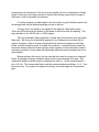
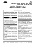
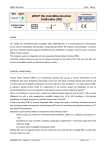
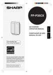
supports that are almost entirely open. Figure one shows a few tube types. To use
one catch-all phrase, I'll borrow a term from the commercial world and call it the OTA,
short for Optical Tube Assembly. In this chapter we’ll examine solid tubes, truss tubes,
simple supports/open tubes and the new string telescopes. I'll examine the solid tube
first.
Figure 1- Three Types of Tubes – Solid, Truss, Simple support
Despite the straightforward task of the OTA, it is the most important structure
we'll deal with when it comes to image degradation. If the tube deforms under its own
weight, or under the combined weights of the components and cameras, finders, etc.,
the image can be degraded. This is most noticeable in very short focus Newtonians,
and Cassegrains or other designs where the secondary contributes magnification. The
longer focus Newtonian design is more forgiving; the image simply shifts due to the
displacement of the reflection from the flat secondary. It will distort, but can shift quite a
bit before that happens.
In contrast to these effects, deformation in the mount is less serious. It means
that the instrument is not pointing at the precise spot in the sky that we think it is, and
the inescapable tolerances of assembly and alignment guarantee that will be the case
anyway. In that sense, we can compensate for deformation in the mount by simply repointing it. Photographers do this all the time when they use a guide star and control
the drive on their telescope.
I. Overview
In the analyses that follow, the approach we'll use is to model the telescope tube
as being held in a cantilever. This is a clamp like the rings commonly used on
equatorials, or the box around a Dobsonian. If you're a woodworker, think of how a
dado joint captures the board in its groove and adds strength to a case. From an
engineering standpoint, this is important because it keeps the tube from moving, and
thereby eases the calculations. Furthermore, we will assume the tube is horizontal with
the full weight at each end acting to deflect the tube. Now horizontal is not the best
position to observe from, so we have chosen the worst case to analyze. As the tube
moves to point higher in elevation, the weight divides into two components, one along
the axis of the tube compressing it, the other perpendicular to the tube causing a
bending moment which decreases as the angle to the horizon increases.
Why a cantilever and not a simple support? The tube is being held in a clamp
ring or box, and that is a cantilever. The clamp may be on a simple support (it is in a
Dobsonian), but that is not the part we are analyzing. Movement of the clamp box does
not affect the image.
The sag in a cantilevered circular tube was covered in chapter two. To review,
sag caused by a load concentrated at one point on a tube clamped at some distance l
from the load is:
F l3
S=
3EI
(1)
where:
I=
π
64
( Do4 - Di4 )
(2)
Do and Di are the outer and inner diameters, respectively, F is the force (usually
weight), E is the Modulus of Elasticity, and l is the length. The angular rotation at the
end (theta, in radians) is described by:
F l2
Θ=
2EI
(3)
Another thing to bear in mind is that the tube will sag under its own weight. You
have seen this when you have lifted something like a long fishing rod by its center; the
ends hang down below the lift point. This was also covered in chapter two, and the
equation for this sag in a cantilever support is:
w L4
Sag wt =
8EI
(4)
The weight shown here is the linear weight density, expressed as pounds per
inch or Newtons per meter. It is obtained by dividing the weight of the tube by its
length. L is the length it acts over (the unsupported length) and the other variables are
3
the same as before. You may find this expressed as WL /8EI where W is the total
weight. The units end up the same, but it is easier to handle the sag in each half of the
OTA the first way. Likewise, the angle at the end can be found by:
w l3
Θ=
6EI
(5)
How Good Does It Have to Be?
This raises the most important question in the design of the tube: how much can
it sag? This is really an optical specification and depends on the type of optical system.
The best way to determine the requirements is through optical raytracing, using a
computer program that allows you to tilt the elements. The companion software to
“Telescope Optics, Evaluation and Design” by Harrie Rutten, and Martin Van Venrooij,
published by Willmann-Bell, will perform this analysis.
Sag will both translate (move in a straight line) and rotate (about the center) the
ends of a tube. In the case of a Newtonian design, the effect is seen on both the
primary and diagonal.
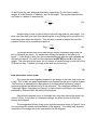
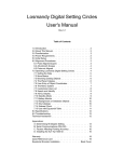
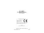
The exaggerated effects of sag on an optical system are shown in Figure 2; here
I've only shown the rotation and translation of the diagonal. The dotted lines show the
movement of the image due to the new position for the diagonal.
Figure 2 - Exaggerated effects of sag on optical performance.
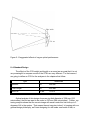
II. A Standard Design
The effects of the OTA weight and length on a mount are so great that it is not
very meaningful to compare mounts if the OTA's are very different. For that reason, I
am going to define an OTA for the analyses in the chapters that follow:
Type
Newtonian
Aperture
10"
250 mm
Focal Length
60"
1525 mm
Mirror wt.
12 lbs.
53.3 N
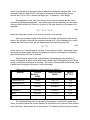
Optical analysis of this design shows an airy disk diameter of .008 mm (315
microinches); the limit we want to be under is .025 mm (984 microinches). Further, raytracing analysis shows that the on-axis image will remain under this limit with up to 2
degrees of tilt in the system. That means the end sags two inches! In keeping with our
general design philosophy, we'll start designing for well under one-fourth of that, or
under 0.5 degree. As you'll soon see, you can do considerably better than even our
safety margin.
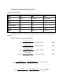
III. Solid Tubes
First, let's look at a round steel tube. This is what a lot of people would think of
first. If we use standard components, we need a tube diameter of at least 11 7/8", so
assume we get a 12" inside diameter cold rolled steel tube that has a 62 mil (1/16")
wall. Here is the design process.
First, calculate I:
I=
π
64
π
( Do4 - Di4 )
(7)
(12.1244 - 12.004 )
(8)
I=
64
I = 42.73 in4
(6)
Since we know the tube will be 60 inches long we can calculate its weight by
π
π
V = ( Do2 - Di2 )h
4
(9)
V = (12.1242 - 12.00 2 )60.00
4
(10)
calculating the volume of the metal and multiplying by the density of steel.
V = 141 in3
wt = 0.284
lb
in
3
(12)
x141 in3 = 40lbs
(11)
We have gathered up all of the other components and weighed them. The
mirror cell weighs three pounds and the mirror 12. The spider and diagonal together
with the focuser weighs 1.5 pounds while the finder and its brackets weigh four pounds.
Given all of this information we can find the CG of the OTA.
Item
Ycg
Wt
Wi*yi
Tube
30 in.
40 lbs.
Mirror
3
12
36
Cell
2
3
6
Focuser/spider
50
1.5
75
Finder
50
4
200
60.5
1517
Sums
1200 in.-lbs.
Thus the CG is at:
Y cg =
1517
= 25.1 in
60.5
(13)
that is, 25.1 inches up the tube from the point we chose as the reference, the bottom.
We'll assume a ring clamp centered at this point.
We need this number to determine the length we use in the sag equation. At this
point, you might to decide to use half the weight of everything except the tube at each
end, since the tube is balanced; this is not accurate, but will give sags worse than the
real value. I will use only the weight that appears on each side (that is, mirror and cell
total of 15 pounds on one side and the spider/focuser/finder total of 5.5 on the other
side), but place that weight at the end of the tube instead of its true position. Since the
sag is strong function of this length (L3), it will also give a worse sag than actual.
So given a length of 25 and 35 inches, the sags due to the weight hanging from
the tube are given by:
3
S = Fl
3EI
(14)
(15)( 253 )
= 63.0x 10⁻⁶ inch
S1 =
6
3(29x 10 )(42.73)
(15)
(5.5)( 353 )
= 63.4x10 - 6 inch
S2 =
3(29x 106 )(42.73)
(16)
so:
and
The sags due to the tube's own weight are:
(40/60) 254
= 26.3x 10⁻⁶ inch
6
8(29x 10 )(42.73)
(17)
(40/60) 354
= 101x 10-6 inch
Swr =
6
8(29x 10 )(42.73)
(18)
Swl =
and
2
3
Θ = FL + wL
2EI 6EI
(19)
In angular terms (expressed in radians) the total is the sum of the rotation from
the load and the tube's own weight:
(40/60)( 253 )
(15) 252
= 5.2x 10⁻⁶
+
Θl =
6
6
2(29x 10 )(42.73) 6(29x 10 )(42.73)
ΘR =
(40/60)( 353 )
(5.5) 352
= 6.6x 10⁻⁶
+
6
6
2(29x 10 )(42.73) 6(29x 10 )(42.73)
(20)
(21)
-6
-6
This sag is equivalent to 676 x 10 degrees (5.2 + 6.6 = 11.8 x 10 radians *
180o/(π radians)). Our requirement of 1/2 degree is 500,000 x 10-6 degrees, so we are
over 700 times better than we need to be.
Many of us would say we're done now, but I don't like the results. In particular, I
don't like the idea of dragging around 60 pounds worth of tube and optics every time I
want to observe. What do we do? How about trading some of that design margin of
700 times for an improvement in weight? Let's look at a different material; aluminum
has a density of 0.098 lbs/in3, or about 1/3 of steel, so a tube of the same size weighs:
W = 0.098
lbs
in
3
141 in3 = 13.8 lbs
(22)
Doesn't 13.8 pounds sound better than 40?
Let's find the CG again:
Item
Ycg
Wt
Wi
Tube
30 in.
13.8 lbs.
414 in.-lbs.
Mirror
3
12
36
Cell
2
3
6
Focuser/spider
50
1.5
75
Finder
50
4
200
34.30
731.00
Sums
Dividing the third column sum by the second column sum, we find that Ycg=21.3
inches.
Now substitute into the same equations:
(15)(21.33 )
= 113x 10-6 inch
6
3(10x 10 )(42.73)
(5.5)(38.7 3 )
= 249x 10-6 inch
S1 =
6
3(10x 10 )(42.73)
(13.8/60)21.34
= 13.8x 10⁻⁶ inch
Swl =
6
8(10x 10 )(42.73)
(13.8/60)38.7 4
= 150.9x 10⁻⁶ inch
Swr =
6
8(10x 10 )(42.73)
S1 =
Again, in angular terms:
(13.8/60)(38.7 3 )
(5.5)38.7 2
= 14.8x 10⁻⁶ (27)
+
Θl =
6
6
2(10x 10 )(42.73) 6(10x 10 )(42.73)
(13.8/60)(21.33 )
(15)21.32
= 8.8x 10⁻⁶ (28)
+
Θl =
6
6
2(10x 10 )(42.73) 6(10x 10 )(42.73)
(23)
(24)
(25)
(26)
Then 14.8 x 10⁻⁶+ 8.8 x 10-6 = 23.6 x 10⁻⁶ radian. Converting this to degrees
yields approximately .0014 degree.
This result is still around 350 times better than we need to be. We saved 26.2
pounds of weight and sacrificed nothing in optical performance. Furthermore, this
weight we just saved turns into even more weight saved in the mount that would have to
be designed to support the heavier telescope tube.
We can repeat this process for any tube you'd care to analyze. A solid kevlar
tube, (75% kevlar, 25% epoxy by volume) has a density of about half that of aluminum,
3
.050 lb/in . A tube with the same dimensions would weigh 7.05 lbs., and would sag less
due to the higher modulus for kevlar (13.6 vs. 10 MPSI for Al.). It may well cost more,
though.
As a point of interest, here's a tube made of a single .010" layer of E glass type
fiberglass.
I=
π
64
(12.024 - 124 ) = 6.80
(29)
E = 0.50( 107 ) + 0.50(4x 10⁵ ) = 5.2x 10⁶
ρ = 0.50(.092) + 0.50(.043) = .067(
lb
in
3
π
(30)
)
Vol = (12.022 - 12.00 2 )60 = 22.64 in3
4
Wt = 22.64 in3 x.067
Given all this we can find the CG again:
lb.s
in
3
= 1.52 lbs
(31)
(32)
(33)
Item
Ycg
Wt
Wi
Tube
30 in.
1.52 lbs.
45.6 in.-lbs.
Mirror
3
12
36
Cell
2
3
6
Focuser/spider
50
1.5
75
Finder
50
4
200
22.02
362.60
Sums
This yields a CG at 16.5 inches. Going straight to the angular calculations
(which is all we really need):
(15)(16. 52 )
= 57.7x 10⁻⁶ rad.
θ1=
6
2(5.2x 10 )(6.8)
(5.5)(43. 52 )
= 147x 10-6 rad.
=
θ2
6
2(5.2x 10 )(6.8)
(.030)(16. 53 )
= 0.6x 10⁻⁶ rad.
θ w 1=
6
6(5.2x 10 )(6.8)
(.030)(43. 53 )
= 11.6x 10⁻⁶ rad
2
=
θw
6
6(5.2x 10 )(6.8)
(34)
(35)
(36)
(37)
where the first two are the angles due to the weight load, and the second two are due to
the tube's own weight.
When you add these sags and convert to degrees, the resultant sag is .012
degree. This is far more than the other designs, but is still over 40 times better than we
need it to be. The only problem with this tube is that the wall is quite thin and the tube
therefore might be prone to buckling. Still, it is strong enough by itself.
To prevent buckling while minimizing weight, we can make the tube thicker with
lightweight foam. The foam doesn't contribute to the tensile strength of the tube, but
adds a great deal to the area moment of inertia. The usual method of construction is to
lay down a layer or two of fiberglass, attach the foam, and then lay down another
couple of layers of fiberglass over the foam. As was just shown, the inner fiberglass
layer is strong enough by itself; the additional material makes it stronger. This ignores
the outer layer. You may have seen pictures of tubes made this way, and some have
shown people standing on the tube. This is impressive, but the load is so different that
it says little about the suitability of the tube as a telescope.
You know from experience that if you take a piece of foam in your fingers, you
can often crush it with fingertip pressure, but can't crush it with the force applied by your
flat hand. For example, I can stand on bubble wrap without breaking it, but can pop the
bubbles by applying much less force with my fingers. Pressure is force divided by area;
a small load on a small area can represent more pressure than a larger load on a larger
area. A small woman in high heels can do more damage to a soft vinyl floor than a
football player in flat shoes; it's due to the small area and high pressure of her heels.
The same situation applies to foam-core fiberglass tubes. A screw going into a
mirror cell or other component can crush the tube in the vicinity of the screw head. This
can be prevented by laminating aluminum flashing strips into the structure, or applying
them to the outside. If laminated in, they must be outside the foam layer. Metal
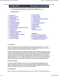
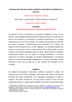
bushings are another good option. Figure 3 shows a cross-section of a composite
tube.
Figure 3 Cross section of a foam-core tube.
Let's look at the design of a foam-core fiberglass tube. Foam core tubes belong
to a class of structures called sandwiches. A sandwich structure is analogous to an I
beam with the facings of fiberglass corresponding to the flanges of the I beam, and the
core to the connecting web. The core must sustain shear stress while preventing the
facings from buckling. The foam and facing must be well bonded to each other with
some sort of adhesive; typically we use the same epoxy used to make the fiberglass. It
is important that the epoxy “wet” the plastic foam and bond thoroughly to both it and the
fiberglass.
There are several approaches to the calculation of the modulus of elasticity for a
sandwich tube, and they vary in the accuracy that they can give. My philosophy in this
analysis is to keep the approach simple. I realize that I could potentially obtain greater
accuracy with another method, but that is balanced by the fact that we don't have the
choice of materials and processes that an industrial composites designer has. If my
calculation tells me that a 0.015 inch layer of fiberglass is strong enough and my
choices are .010 or .025, I choose the larger one. In essence, I over-design.
The approach to use, then, is a version of the rule of mixtures that we use to
calculate the fiberglass properties. This version says that the sandwich can be said to
have an effective value for E that is a function of the area fractions of the parts of the
sandwich.
E eff = E f A f + E c Ac
(38)
where the subscript c refers to the core and f refers to the facings.
Since the numerical value for the areas of the faces and the core is almost the
same if the cylinder is thin and the numerical values for E of the fiberglass is so much
greater than that of the foam, we can approximate the result by saying that:
E eff ≈ E f
(39)
or the value for E is determined by the skin of the composite alone. Essentially, when
the composite piece takes the load, the weak core wants to come apart, but the load
gets carried by the stiff shell of the tube.
What we have gained, then, is dramatically increasing the area moment of
inertia, making the structure much stiffer than a single layer of fiberglass by itself while
giving it much more resistance to buckling. The foam, if bonded well to the facing, adds
a great deal of strength at the cost of very little weight.
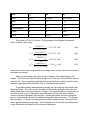
Plastics often encountered in foams are listed in table 3-1.
Material
Young's
Modulus
(KPSI)
Tensile Strength
(KPSI)
Density
(10-6 PCI)
Polyethylene LD
15-40
0.60-3.0
19.2
Polyethylene HD
60-180
3.00-5.50
20.1
PVC
300-600
5.00-9.00
29.2
Polystyrene
380-450
3.20-8.00
22.2
Nylon
400-500
11.0-12.0
23.8
The quantities listed are for the plastics themselves, to use these values for a
foam, you need to know the volume fraction for the plastic in the foam and then use the
rule of mixtures. Most foams are in the range of 3-5% plastic and the rest gas of some
sort. Just use 3-5% of the table's values to approximate the value for the foam.
Let's look at a tube made from two layers of .010 in. S-glass, separated by 0.25
inch of PVC foam. We'll assume a 50-50 mix of S glass and epoxy. Using the Rule of
Mixtures, we find:
Ec = (12.6x 10⁶ )(0.50) + (4x 10⁵ )(0.50) = 6.5x 10⁶
(40)
and
ρ = (0.090)(0.50) + (.043)(0.50) = .0665
lbs
in
3
(41)
In this sort of composite tube, the glass is in two shells and the foam in the
middle. The areas of the glass and foam can be used to find the percentage of each.
Aglass =
π
4
((12.0102 - 122 ) + (12.2702 - 12.2602 )) = .381 in2 (42)
A foam =
π
4
(12. 2602 - 12.0102 ) = 4.765 in2
(43)
The percentage of glass in the mixture is:
% glass =
.381
x100 = 7.4%
4.765 + .381
(44)
Finally, the percent foam is what's left, 92.6%. The foam is only part plastic,
though, so we'll say it's 4% (a rough number from the above discussion). The density
of the tube is then:
ρ tube = (.0665)(.074) + (29.2x 10⁻⁶ )(.926)(.04) = 4.92x 10⁻³ (45)
The tube volume is:
Vol =
π
4
(12. 2702 - 12.002 )60 = 308.8 in3
(46)
and 308.8 * .00492 weighs 1.52 pounds. Remarkably, and purely by coincidence, this
is the same as the E glass tube we just looked at. We fill in the table again:
Item
Ycg
Wt
Wi
Tube
30 in.
1.52 lbs.
45.6 in.-lbs.
Mirror
3
12
36
Cell
2
3
6
Focuser/spider
50
1.5
75
Finder
50
4
200
22.02
362.60
Sums
This yields a balance point up 16.5 inches from the base.
The moment of inertia for this tube is larger than before, I=84.75 in4. The linear
weight density is 1.52 pounds over 60 inches, or 0.0253 pounds/inch, less than before.
Going straight to the angular calculations (which, again, is all we really need),
first due to the end loads:
θ1=
(15)(16.52 )
= 3.71x 10⁻⁶ rad.
6
2(6.5x 10 )(84.75)
(47)
(5.5)(43.52 )
= 9.4x 10⁻⁶ rad.
6
2(6.5x 10 )(84.75)
(48)
θ2=
and the following are due to the tube's weight.
θw 2=
(.0253)(43.53 )
= 6.3x 10⁻⁶ rad
6
6(6.5x 10 )(84.75)
θ w 1=
(49)
(.0253)(16.53 )
= 0.34x 10⁻⁶ rad.
6
6(6.5x 10 )(84.75)
(50)
When you add these sags you get 19.75 microradians. When converted to
-3
degrees, the resultant sag is 1.13 x 10 degree.
This value is around 450 times better than our requirement. We have gained an
improvement of over 10 times in stiffness over the thin fiberglass tube above and the
only thing it cost us is the labor to build such a tube.
Finally note that this tube approaches the rigidity of steel in less than two
pounds, while the steel tube weighed in at 40 pounds. Later on, we’ll discuss how to
build this kind of tube.
V. Simple Supports
To contrast with the ultimate in high tech tubes that we just examined, let's look
at the simplest OTA you can make. Besides, it leads in to the next area nicely.
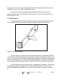
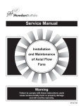
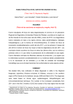
Figure 4 – A Simple Support
Figure 4 shows a support made from a single piece of 2x12 dimensional lumber.
If you buy it in finished form from the lumber store, this piece will measure close to 1.5
x 11.5. The mirror cell is mounted to supports that are joined to the beam; the diagonal
holder also is attached to it. The flange on the side supports a couple of pieces of pipe
for an old fashioned pipe-thread mount, so the OTA can move in azimuth or elevation.
All of the analysis we have shown so far is applicable to this design. The density
of southern pine given in chapter two is .022 pounds per cubic inch: a 2 x 12 x 60
(inches) will therefore weigh about 22.7 pounds. The moment of inertia for this beam
is:
I=
1 3
1
3
4
bh = (1.5)(11.5 ) = 190 in
12
12
(51)
Assuming a value for E of 1.6x10⁶ psi, the total sag is 2.3x10⁻³ degree, well
within our desired limit.
This OTA, though, will exhibit a characteristic we haven't examined yet: torsion
or twisting. There is a torque applied to the end of the board at the center of gravity of
the mirror. The 12 pound mirror and its mounting cell put a downward force that acts at
their center of gravity six inches from the end of the beam. The angle of the twist is
described by:
φ=
TL
3
c2 a b G
(52)
where T is the torque in inch-pounds, L is the length of the rectangular beam that is
twisting, a is the long dimension of the rectangle, b is the short dimension, G is the
shear modulus and c2 is a constant that depends on the ratio of a to b. Here is a table
of values for c2 and c1 (another constant I'll get to in a minute).
a/b
c2
c1
1.0
.141
.208
1.2
.166
.219
1.5
.196
.231
2.0
.229
.246
2.5
.249
.258
3.0
.263
.267
4.0
.281
.282
5.0
.291
.291
10
.312
.312
infinite
.333
.333
The value for G is often not tabulated for woods, but can be approximated by 1/4
of E, if the stress is perpendicular to the grain as it is here.
That said, all that is left is to plug numbers into the equation. T = 12lbs x 6in =
72 in-lbs.; L= 23 in (to the support), a/b = 7.6 so I'll approximate c2 as 0.3. Then
φ=
72in - lbs x23in
lb.s
0.3(11.75in )(1.75 in )(300x 10 2 )
in
3
3
3
= 0.016°
(53)
The maximum shear stress caused is:
T
2
c1 a b
(54)
lb.s
72in - lb.s
=
6.7
2
0.3(11.75in )(1.752in2 )
in
(55)
τ max =
τ max =
The value of 6.7 psi compares to the bursting stress of around 380,000 psi.
The simple support can be improved by supporting the mirror in a box that is
attached to the bottom of the wooden beam. The altitude bearings are attached to the
box and the support on both sides eliminates the torsion twist caused by the weight of
Figure 5
the mirror. See figure 5. It also provides a very large moment of inertia. Since the sag
contributed by the back end of the box is much smaller (due to its combination of short
length to the mirror and large moment of inertia) than the sag caused by the length of
the beam, it can be ignored in the analysis.
It is often necessary to add weight to the mirror box to get the balance point to be
far enough back that the altitude bearings can be on the box.
The sag, then, is caused by the weight of the diagonal, finder and focuser.
These are 50 inches from the bottom of the beam or 44 inches from the bearing. The
sag calculates to be .00139 inch, or .0026 degree.
This is a moderately heavy approach, heavier than the aluminum tube yet lighter
than steel. Still it may be an attractive approach for a Dobsonian mount that will be
used in one place. Due to its open construction that won't even support a cloth light
shield, it will be limited for use in truly dark sky locations. It could be broken down for
travel with clamps where the beam and box come together, but the demands of travel
are better served by a truss made with lightweight pipes that can be wrapped up into a
small bundle.
Before we leave this mount, let me note that the board is serving as a classical I
beam; its strength is being contributed solely by the outer extremes of its area. This
means that weight could be saved by replacing the solid 2 x 12 with something like a
pair of 2 x 4s. The focuser and finder could be accommodated by adding a 1 x 8, 1 foot
long at the top. You could even replace the two by fours with angle iron or aluminum
pipe.
Figure 6 - Ron Ravneberg's "Scope Like Alice"
One of the most copied small scope designs found online is built like this: a box
holding the mirror and cell, with two poles supporting the focuser, spider and diagonal.
The original was called “Alice”, and several adaptations have been made. ATM Ron
Ravneberg published his version online at:
http://www.atmsite.org/contrib/Ravneberg/alice/ It’s obvious that Ron is quite a
talented woodworker, too!
VI. Truss Tubes
In contrast to the solid tubes, the truss is an open tube. In contrast to the simple
supports just covered, it is more closed. Regardless, trusses are familiar to anyone
with any reading exposure in astronomy. They are the mainstay of the professional
observatories and extensively used in the amateur community. The truss itself has
been used in civil engineering for centuries as an essential part of bridge and building
construction. Virtually every roof on every house in America uses trusses to support
the load. It is an old civil engineer's axiom that bigger and heavier is not always
stronger; it's also one that I've adopted.
In the size of our standard design, there is not necessarily a weight decrease by
going to a truss, especially if the tube is a foam/fiberglass composite. There is, though,
a strong advantage in portability, something that is a big concern if you are taking your
telescope places in your car.
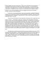
There are two main types of truss assemblies commonly used in telescopes and
shown in Figure 7. The design on the left is a simple truss often used in Dobsonian
mounts, such as the Tectron® and Obsession® models. It is also used in professional
instruments such as the 4 meter Mayall Telescope on Kitt Peak. In Dobsonians, these
telescopes are balanced back-heavy (easier to do with a full-thickness mirror) and
supported by altitude bearings on the bottom box. The other type of truss, shown on
the right, is called the Serrurier truss. This is used in homebrew scopes as well, and
was designed by Serrurier for the 200 inch Hale telescope on Mt. Palomar. The truss
members are mounted at 90 degree intervals around all of the segments, with the ends
at the top and bottom optics-holding rings rotated 45 degrees with respect to the middle
ring.
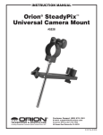
The Serrurier truss has a property that almost seems magical, even today, half a
century since its development. When a load is applied at both ends, the truss sags into
essentially a parallelogram, with the ends rotating much less than a solid tube will
rotate. Since the ends remain essentially parallel, the effects on image quality are very
much reduced. The Serrurier truss is an excellent choice for a large telescope that will
have a high center of gravity.
Figure 7 A simple truss (left) and a Serrurier truss (right)
The analysis of a truss is not as straightforward and as the analyses we've done
so far, although it is part of virtually every mechanical engineer's training. The basic
approach is to compute the forces on each member and from that calculate its
deformation. Each member is described by six equations (three force and three
moment), so a simple, four-tube truss requires the solution of up to 24 equations. You
can see that this is tedious work. There is a simplification of this that is valid only for
altazimuth mounts; I'll get to it in a few paragraphs.
Because of this, I recommend a computer approach to the problem, using what
is called the Finite Element Method (or Finite Element Analysis). The FEM programs
take as input a description of the truss, usually the coordinates of the ends of members,
called nodes; a description of the elements of the truss; material used; geometry (tube,
2x4, etc.); and the expected loading. Depending on the program's features, it may
allow point loads, uniform loads, and thermal gradients. The output can be graphical
displays, tables of the new positions of the nodes, or both, and (rarely) resonant
vibration frequencies. Since the deformations we are concerned with are small, the
programs typically magnify the effects of the deformation so that they can be seen on
the scale of the whole assembly.
For those who are interested in pursuing this sort of analysis, I've evaluated a
pair of FEM programs available as shareware for the IBM PC family and its clones.
They are called PCSTRAN (PC STRuctural ANalysis) and GRAPE3D (Graphic Realtime Analysis Programs for Engineering). Both were obtained from a shareware
vendor. Both are capable of the required analysis and give good performance. My
personal choice is GRAPE3D, primarily because I like its graphical interface better. I
have used it for the analyses in this section.
A simple truss was modeled as a part of a 60 inch long OTA. The base section
holding the primary and the top section holding the secondary and focuser are each
one foot long, leaving a 36 inch long simple truss to join them. The truss is designed
like the one on the left in figure 6, and modeled as aluminum tubing on 13" centers.
A truss made of 1/2 inch OD #18 aluminum and one of 1 inch OD #16 aluminum
were both modeled. The small tube will allow roughly .006 inch of sag, while the larger
tube will allow .002 inch. This is due to the effects of its own weight and a six pound
load at the end. The angular sag for the small tube is 2.41 x 10⁻³ o; for the large tube it's
-3 o
1.02 x 10 . Either one will provide excellent results. These numbers are essentially
the same as those of the solid 12" aluminum OTA, yet the truss uses less material and
weighs less than the solid aluminum one.
The angular sag I've calculated comes from the displacement of the ends of the
truss, a different calculation than the one I've used before. The FEM program outputs
the coordinates in three-dimensions of the ends of the truss. The angle I've calculated
is the angle between the planes formed by the end of the truss before and after
deformation.
Several times in this book, I've emphasized the idea of using triangles in your
structures instead of squares. For comparison, I modeled a square truss with four 1/2
inch # 18 Aluminum tubes at the corners of a 13 inch box. The beginner may be
tempted by this design: it is simple and uses half the number of tubes that the trianglebased truss does. Don't do it. It deflects a whopping 0.4 inch; 165 times the deflection
of the triangular truss, and much more than anything we've looked at.
The triangular truss transforms bending forces into forces of compression and
tension in the elements; this is the strongest way to load any structure. The truss
elements tend to deflect more at the middle than they do at the ends (they are trying to
buckle), and the middles of the truss tubes can be reinforced to increase their crosssectional area and reduce deflection even more.
How would you scale up a truss for a larger telescope? The important
parameters are the weight that it must support at the end, and the length of the truss. I
modeled a truss like the previous one, except with a diameter of 26 inches and a length
of 100 inches. Such a truss may be needed for a 24 inch f5 Newtonian. I increased
the load at the top end to 10 pounds. When built of 1" tubing, this truss showed a
deformation of about 0.15 inch. Going to 1.5" #16 tubing reduced this to .02 inch.
Even for the largest amateur telescopes, 30 inches or greater, tubing less than 2 inches
OD should suffice. If you are going to invest that sort of money in a mirror and
telescope, I urge you to look into the design with an FEM program.
A Simplification for the Altazimuth Mount
If you are going to put a truss tube on an equatorial mount, there is no substitute
for the FEM analysis just discussed. In the case of the Dobsonian (or any other
altazimuth mount), though, there is a simplification that is powerful enough to deserve
separate mention.
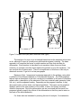
Figure 8 Gary Wolanski’s aluminum 16" truss Dob can be analyzed with this method.
Consider the side view of a Dobsonian with a square mirror box as shown in
Figure 8. One of the great advantages of an altazimuth mount is that the load on the
mount is always in one direction. This fact simplifies the analysis. The truss can be
thought of as four triangles made from tubes; two are vertical and two are horizontal.
The two horizontal triangles are loaded like simple cantilever beams and the triangular
shape doesn't add strength because the load is perpendicular to the long base of the
triangle. The vertical triangles, on the other hand, are loaded parallel to their base and
the strength does get improved by the triangular shape. The shape transfers the
bending load from the weight into a load that stretches the top piece and compresses
the lower piece. The top and bottom triangles would deflect more than the side
triangles, but the stronger sides end up carrying the load. In fact, we can safely ignore
the top and bottom triangles and find the deflection simply by calculating the deflection
for one side carrying one half of the weight from the secondary and supporting tube
section.
The deflection in the truss is then easily calculated by the following equation:
3
S = WL
2
c AE
(56)
where c is the base length of the triangle (the distance between the ends of the truss
tubes), A is the cross-sectional area of the truss tubes, W is one half of the load and E
has its usual meaning. This method was pointed out by Roy Diffrient in Sky and
Telescope for February 1994. It ignores the deflection in the truss from the tube's
weight, something that can be accommodated in an FEM program, but the simple
equation makes it worthwhile to do this for altazimuth mounts. A cheap and dirty
approximation to including the effects of the tubes weight is to add the weight of half of
the tubing to W (half because we only do this for one side of the truss).
How good is this approximation? I have compared results from a 10 pound load
on a truss tube simulated with FEM software and this simplified method. The results
are within 10%, and the simple model gives more pessimistic answers; that is, it says
the sag is worse than the FEM software says. If a design meets your requirements with
this method, it will be better than you think.
It is possible to use this as an approximation for the deflection that would be
found with an equatorial mount, but more analysis should be done (or larger truss tubes
used) if you find that the deflection is too great. Buckling could possibly be a concern
with very small diameter truss elements. Suffice it to say that a large safety margin is
called for here, because buckling would be a terrible catastrophe for the telescope.
Picture your secondary falling onto your primary, and you get the idea! As pointed out
above, even moderately sized tubes work well in a truss, so there's no reason to push
your luck except for the most ambitious attempts to minimize weight.
Remember that Euler's equation for the load that causes buckling is:
P= π
2
EI
L
2
(57)
and including the equation for moment of inertia of a circular tube, this reduces to:
P= π
3
E( d o4 - d i4 )
64 L2
(58)
If you want to be very cautious, multiply that 64 by 8 or 10 to give yourself that safety
factor. I'd recommend staying with at least 6.
Figure 9 - The side triangles provide all the strength in this geometry. The top and
bottom triangles are easier to bend.
A whole new generation of giant Dobsonians is being born based on these truss
designs, and will be discussed in a later chapter. For the optical use these telescopes
get, the smaller truss tubes are sufficient.
VII. String Telescopes
One of the more interesting innovations of the late 1990’s/early 2000’s in
telescope making is the idea of string telescopes. It appears that the original was
invented by Dan Gray for friend named Jane, and posted on this web page, which may
be the most circulated web page in ATM history:
http://www.tms-usa.com/grayarea/janes16/jane16.htm
The principal of the string telescope is to replace the elements of a truss that are
only in tension with non-stretchable string. Kevlar cords from the archery world were
the first strings. Of course, there is no such thing as loading a string in compression so
there must be some elements that take the compressive loading. If you keep these
elements loaded in tension pinned at the corners of a triangle, they can only move
perpendicular to the plane of the triangle. By using a group of them tied to the upper
cage assembly, no movement can take place: all that is needed is to keep the strings
under tension.
To quote from Dan Gray (8),
“To further explain the concept, imagine two strings anchored in your garage
floor about 2 feet apart, and tied together about 5 feet in the air. Grab the knot with
your finger, pull the strings taut, and now you can only move the string in an arc,
forward and back, not left to right. Now make another pair of strings, and anchor them
to the floor, 120 deg.s apart from the first pair. Grab the knot with your other hand, and
it also is only able to move in its own arc, 120 deg.s from the first arc. Add a third pair
another 120 deg.s apart, and have your imaginary friend hold it at its knot, and it too
has its own arc. Now tie the three knots together with a secondary cage, and now the
only way to move the secondary cage is to slack a string. Keep enough tension on it,
and it will stay in the same place relative to the garage floor. Now it should be easy to
see how it would work on a telescope.
This has five advantages over a truss tube telescope:
1. It will be lighter; you would need at least three pairs of trusses to do the same thing.
These trusses can be pretty light if you use expensive carbon fiber, but will certainly be
much heavier than string and two spring poles.
2. It is much quicker to set up. The strings are always connected when the telescope is
not in use. To set up the telescope, simply grab the secondary cage and extend it, and
then insert the two (or three) spring loaded side poles.
3. No collimation is necessary after setup, as the fiberglass strings do not stretch, and
will always position the secondary cage to exactly the same place.
4. Less wind resistance.
5. Simplifies the secondary holder design, as the secondary adjustment (in relation to
the primary mirror) is done with the strings.
Keep 4 things in mind if you intend to make a successful string telescope:
1. Use low stretch string, and double it over many times. Dan uses Kevlar bow string.
2. Use 3 pairs of strings, and 3 poles. Using 3 poles means your secondary cage
doesn't have to be as stiff, and you need 1/3 less pressure to keep the strings taut.
3. Be sure your mirror box is stiff enough not to warp with the pressure from the strings
and poles.
4. Make your secondary cage as light as possible!”
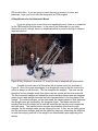
Figure 10 - Dan Gray's 28" and 16" ("Jane's String Telescope") at RTMC. Copyright
Dan Gray
Practical string telescopes use two or three rods loaded in compression as the
springs that keep everything positioned. This creates push-pull couples – a
combination of 2 forces acting on a body through the same center of rotation – on the
rocker box and upper cage assemblies. This increases the amount of strength required
out of the assemblies compared to static loading from gravity and their own weights. A
couple can only cause rotation, but the fasteners can rip out of the rocker box or upper
cage if they are not secure enough under those loads.
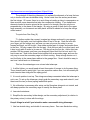
VIII. Wind Induced Vibration in Truss Tubes.
The preceding analysis shows that you can use surprisingly thin truss tubes and
yet maintain adequate mechanical stiffness to preserve acceptable collimation. That's a
good analysis of static forces in a static environment. Now let's step outdoors into the
breeze.
Recently ATM’s Martin Cibulski and Tom Krajci (6) pointed out that the diameter
required to reduce sag and hold collimation may not be optimum, and that the designer
should pay attention to another aspect of truss tube design. Specifically truss tube
resonant frequency, and the frequency of vortex shedding (from the truss tubes) that
occurs in moving air. Why is this a big deal? Because if the resonant frequency of a
truss tube matches the frequency of vortex shedding, you may get significant,
continuous vibration. Yes, but doesn't this only happen in very high winds? Not
necessarily. It depends on several factors.
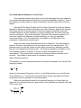
Ever notice how a flag waves back and forth in a breeze? This was studied by
physicist Theodore Von Karman and is now known as the Von Karman effect. The
breeze moving over the flag causes a vortex which moves along, detaching from the
flag only to be replaced by another vortex. This behavior happens at all scales of size,
from islands to cables in a breeze. Ever seen a spiral rail wrapped around a
smokestack? This is being done to break up the vortex and reduce stresses on the
structure. The problem is even worse in underwater structures.
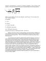
Martin Cibulski pointed out:
The frequency of the air turbulence behind a truss can be calculated. (It is used for flow
metering in pipes.)
f
0.2 ⋅
v
D
where f is the resonant Frequency in Hertz, v is the Wind velocity in m/s, and D is the
Truss diameter in m. The formula shows that thinner trusses have higher turbulence
frequencies, since the diameter is in the denominator.
Martin also provided the math for the resonant frequency of a truss tube: the
formula is for a cylindrical bar (not a pipe) which is held rotatable at both ends (like most
ATM trusses are):
f
( D ⋅π )
( 8 ⋅L2)
⋅
E
ρ
where D = outer diameter, L = length, E = modulus of elasticity, ρ (rho) = density of the
material. This can be corrected for a pipe by compensating for the missing material:
f
(π )
( 8 ⋅L )
2
⋅
E
ρ
⋅
4
4
2
2
D −d
D −d
With one new variable, d for the inner diameter. Use SI Units: l, D, d in meters, E in
N/m2, and rho in kg/m3.
An example:
l = 1.5 m
D = 20 mm
d = 18 mm (1mm wall)
E = 69e9 N/m2 (aluminum)
rho = 2650 kg/m3 (aluminum)
The resonant frequency calculates as 23.96 – call it 24 Hz.
Based on the above math for vortex shedding, what wind speed is needed for a
20mm diameter tube to have a vortex shedding frequency of 24 Hz? Only 2.4 meters
per second (5.4 miles per hour). This sort of wind occurs virtually every night in my
observing areas.
If you look at the first equation, that shows the resonant frequency of a truss, it
shows that the resonant frequency is directly proportional to the diameter, but only to
the square root of the Elastic modulus. That means that making the diameter larger
has a larger effect than increasing the stiffness of the tube. Assuming carbon fiber
tubes, for example, your truss tube resonant frequency goes up 40 - 53 Hz. That’s nice,
but with the same diameter, it will only take a breeze of 4-5 meters per second (9-12
miles per hour) to reach the resonant frequency. These wind speeds are still very
common where I observe. What if we go back to aluminum, but double the diameter of
the truss tube to 40mm? Truss tube resonant frequency jumps to 50 Hz (same as for a
smaller carbon tube), but because the tube is twice the diameter...it takes a higher wind
speed...about 10 meters per second (22 miles per hour). This is windy enough so that
you probably stop setting up your scope to observe. Earlier in the book, I
recommended designing for resonant frequencies above 30 Hz; this is an example of
why you would go higher.
In the quest to push ultra-light truss tube amateur telescopes to new limits, there
is a risk of making your instrument unusable in any but dead calm winds. Do you
observe in such a place?
You may note that many of the truss tubes use foam pipe insulation around the
tubes. This acts to enlarge the diameter that affects this vortex formation. That may be
why there seem to be so few complaints about this problem.
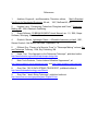
What about string telescopes? What sort of vortex shedding properties do they
present? The resonant frequency of a string is taught in all basic physics classes. The
resonant frequency, F, is:
T
m
f
L
2 ⋅L
(m/L) is a quantity called the “Linear Density” of the string, its mass divided by its length.
L = the length of the string and
T = the tension in the string.
There is no particular need to use SI units, just be consistent.
The undersea drilling industry has this problem with current flowing around
pipes. They use strakes to break up the vortex. A strake is a helical member wrapped
round the outside of a cylinder. It causes the vortex separation point to be at different
positions along the cylinder. The vortex shedding then becomes incoherent (different in
phase at different positions) along the cylinder, which minimizes most of the
undesirable effects. Strakes are used in a variety of applications, from these undersea
pipes to steel chimneys. There are even commercial standards for the size and pitch of
the strakes in different applications.
References
1.
Avallone, Eugene A., and Baumeister, Theodore, editors,
Mark's Standard
Handbook for Mechanical Engineers, 9th ed., 1957, McGraw-Hill, Inc.
2.
Hughes, Larry, “Constructing Tubes from Fiberglass and Foam”, Telescope
Making #42, 1990, Kalmbach Publishing
3.
Grape Software, 3D BEAM ELEMENT User's Manual, ver. 1.5, 1992, Grape
Software, Winnipeg, Manitoba, Canada.
4.
Overholt, Steven, Lightweight Giants -- Affordable Astronomy at Last!, 1991,
Steven Overholt, Owl Books, San Juan Capistrano, CA
5.
Diffrient, Roy, “Flexure of a Serrurier Truss” in “Telescope Making” column, Sky
and Telescope, February, 1994, Sky Publishing, MA
6.
Krajci, Tom, “One Approach to the Dobsonian Telescope”, published online:
http://www.atmsite.org/contrib/Krajci/scope-design.htm
7.
Mark Tools Products, “Vortex Induced Vibration Suppressors”, at
http://www.marktool.com/suppressors.html and http://www.marktool.com/vivs.html
8.
Gray, Dan, “MY 28 INCH STRING TELESCOPE”, published online at:
http://www.siderealtechnology.com/28inch/
9.
Gray, Dan, “Jane’s String Telescope”, published online at:
http://www.tms-usa.com/grayarea/janes16/jane16.htm