1
Czech Technical University in Prague
Faculty of electrical engineering
DIPLOMA THESIS
Řı́zenı́ pohonů na FPGA v sı́ti Profinet
Praha, 2015
Autor: Tomáš Ryčl
Prohlášenı́
Prohlašuji, že jsem svou diplomovou (bakalářskou) práci vypracoval samostatně a použil
jsem pouze podklady (literaturu, projekty, SW atd.) uvedené v přiloženém seznamu.
V Praze dne
podpis
i
Acknowledgment
I would like to express my gratitude mainly to Ing. Pavel Burget, Ph.D. for his supervision in a form of consultations, help with obtaining important material for the work,
constructive comments and help with solving some practical issues that arose during the
process. I would like to thank as well the experts from Softing Industrial Automation
GmbH and Siemens, s.r.o. for their quick and top quality technical support.
ii
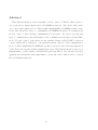
Abstrakt
Tato diplomová práce se zabývá návrhem zařı́zenı́, založeném na FPGA, které bude
schopné fungovat jako vzdálené vstupně-výstupnı́ zařı́zenı́ v PROFInet sı́ti. Zařı́zenı́ bude
obsluhovat jeden či vı́ce třı́fázových motorů. Bude potřeba na FPGA implementovat
PROFInet stack, který umožnı́ komunikaci v PROFInet sı́ti. Pro synchronnı́ řı́zenı́ vı́ce
vzdálených motorů je důleľžitá rychlá real-time komunikace, proto je třeba zvolit takovou
implementaci sı́ťového protokolu, která umožňuje komunikaci v režimu Isochronous Real
Time. Pro lokálnı́ řı́zenı́ samotných motorů bude použita dostupná softwarová knihovna
pro řı́zenı́ motorů zvaná PXMC, která bude upravena pro náš konkrétnı́ systém. Nad
komunikačnı́m protokolem bude implementován PROFIdrive profil pro řı́zenı́ motorů a
jejich snadnou integraci do existujı́cı́ch procesů. Práce se nezabývá detailnı́m návrhem
jednotlivých součástı́, ale využitı́m existujı́cı́ch aplikacı́ a knihoven a jejich úpravou a
syntézou k vytvořenı́ zařı́zenı́ schopného fungovat ve skutečné průmyslové sı́ti.
iii
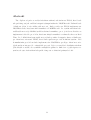
Abstract
This diploma thesis is about designing a device, based on FPGA, that is able to
act as an remote input-output device in PROFInet network. The device will control
one or more three-phase motors. That requires implementing a PROFInet stack on the
device that allows the device to communicate in PROFInet network. For synchronous
motion control, a fast real-time communication is necessary. In order to provide this
type of communication, the stack must be able communicate in Isochronous Real Time
mode. For the control of the drives we use available library called PXMC for motion
control, which will be adjusted to our particular system. On top of the communication
protocol will be implemented PROFIdrive profile for motion control and easy integration
of the device into already existing industrial processes. This diploma thesis doesn’t cover
implementing of each software and hardware part but aims to use already developed
applications and libraries and adjust them to create the device that is able to work in
the real industrial network.
iv
v
vi
Contents
List of Figures
ix
List of Tables
xi
1 Introduction
1
2 System Description
5
2.1
System overview
. . . . . . . . . . . . . . . . . . . . . . . . . . . . . . .
5
2.1.1
System controller . . . . . . . . . . . . . . . . . . . . . . . . . . .
7
2.1.2
PROFInet IO device . . . . . . . . . . . . . . . . . . . . . . . . .
8
2.1.2.1
PROFInet Stack . . . . . . . . . . . . . . . . . . . . . .
9
2.1.2.2
PROFIdrive Stack . . . . . . . . . . . . . . . . . . . . .
9
2.1.2.3
Main Application . . . . . . . . . . . . . . . . . . . . . .
9
2.1.2.4
Motion Control . . . . . . . . . . . . . . . . . . . . . . .
10
Motor and adaptation circuit . . . . . . . . . . . . . . . . . . . .
10
2.1.3
3 Components and Technologies Used
3.1
11
Communication Protocol - PROFInet . . . . . . . . . . . . . . . . . . . .
11
3.1.1
Industrial Ethernet . . . . . . . . . . . . . . . . . . . . . . . . . .
11
3.1.2
PROFInet RT/IRT . . . . . . . . . . . . . . . . . . . . . . . . . .
13
3.1.2.1
Cyclic data exchange . . . . . . . . . . . . . . . . . . . .
13
3.1.2.2
Acyclic data exchange . . . . . . . . . . . . . . . . . . .
14
GSDML . . . . . . . . . . . . . . . . . . . . . . . . . . . . . . . .
15
PROFInet Stack . . . . . . . . . . . . . . . . . . . . . . . . . . . . . . .
18
3.2.1
Hardware Components . . . . . . . . . . . . . . . . . . . . . . . .
19
3.2.2
SDAI . . . . . . . . . . . . . . . . . . . . . . . . . . . . . . . . . .
20
3.3
Altera board . . . . . . . . . . . . . . . . . . . . . . . . . . . . . . . . . .
20
3.4
Altera tools . . . . . . . . . . . . . . . . . . . . . . . . . . . . . . . . . .
21
3.1.3
3.2
vii
3.5
3.4.1
Quartus II . . . . . . . . . . . . . . . . . . . . . . . . . . . . . . .
21
3.4.2
Eclipse IDE for NIOS II . . . . . . . . . . . . . . . . . . . . . . .
22
3.4.3
NIOS II Command Shell . . . . . . . . . . . . . . . . . . . . . . .
22
3.4.4
NIOS II Processor . . . . . . . . . . . . . . . . . . . . . . . . . .
23
PXMC . . . . . . . . . . . . . . . . . . . . . . . . . . . . . . . . . . . . .
24
4 Implementation
4.1
PROFInet stack
4.1.1
4.1.2
4.2
4.3
4.4
25
. . . . . . . . . . . . . . . . . . . . . . . . . . . . . . .
26
Hardware design . . . . . . . . . . . . . . . . . . . . . . . . . . .
27
4.1.1.1
Inputs/Outputs for motor . . . . . . . . . . . . . . . . .
27
4.1.1.2
PWM generator . . . . . . . . . . . . . . . . . . . . . .
28
4.1.1.3
Quadrature Counter . . . . . . . . . . . . . . . . . . . .
30
4.1.1.4
Complete Design . . . . . . . . . . . . . . . . . . . . . .
32
. . . . . . . . . . . . . . . . . . . .
32
4.1.2.1
Note about Debugging . . . . . . . . . . . . . . . . . . .
33
4.1.2.2
SDAI Initialization
. . . . . . . . . . . . . . . . . . . .
34
4.1.2.3
SDAI Data Exchange
. . . . . . . . . . . . . . . . . . .
40
4.1.2.4
Main Application . . . . . . . . . . . . . . . . . . . . . .
42
. . . . . . . . . . . . . . . . . . . . . . . . . . . . . . . . . . . .
43
4.2.1
Hardware design . . . . . . . . . . . . . . . . . . . . . . . . . . .
44
4.2.2
Software design . . . . . . . . . . . . . . . . . . . . . . . . . . . .
46
PXMC
Software Application Design
PROFIdrive
. . . . . . . . . . . . . . . . . . . . . . . . . . . . . . . . .
46
4.3.1
Module specifications . . . . . . . . . . . . . . . . . . . . . . . . .
50
4.3.2
Parameter model . . . . . . . . . . . . . . . . . . . . . . . . . . .
51
Testing . . . . . . . . . . . . . . . . . . . . . . . . . . . . . . . . . . . . .
53
4.4.1
PLC . . . . . . . . . . . . . . . . . . . . . . . . . . . . . . . . . .
53
4.4.2
PROFIdrive Profile Tester . . . . . . . . . . . . . . . . . . . . . .
54
5 Conclusion
57
A Contents of the CD
I
viii
List of Figures
1.1
Printing Press
. . . . . . . . . . . . . . . . . . . . . . . . . . . . . . . .
2
2.1
Overall schema . . . . . . . . . . . . . . . . . . . . . . . . . . . . . . . .
6
3.1
SendCycle example . . . . . . . . . . . . . . . . . . . . . . . . . . . . . .
14
3.2
GSDML Header
17
3.3
FPGA hardware components
3.4
Altera interconnection schema
. . . . . . . . . . . . . . . . . . . . . . . . . . . . . . .
. . . . . . . . . . . . . . . . . . . . . . . .
19
. . . . . . . . . . . . . . . . . . . . . . .
23
4.1
Top level functionality . . . . . . . . . . . . . . . . . . . . . . . . . . . .
26
4.2
Qsys application subsystem IO
. . . . . . . . . . . . . . . . . . . . . . .
28
4.3
Modelsim pwm simulation . . . . . . . . . . . . . . . . . . . . . . . . . .
29
4.4
Quadratic counter simulation . . . . . . . . . . . . . . . . . . . . . . . .
31
4.5
Debounce filter . . . . . . . . . . . . . . . . . . . . . . . . . . . . . . . .
31
4.6
Top-level IO for motion control . . . . . . . . . . . . . . . . . . . . . . .
32
4.7
SDAI and stack initialization
. . . . . . . . . . . . . . . . . . . . . . . .
34
4.8
SDAI units plugging . . . . . . . . . . . . . . . . . . . . . . . . . . . . .
39
4.9
IO application memory
. . . . . . . . . . . . . . . . . . . . . . . . . . .
40
4.10 Plugging of IO modules
. . . . . . . . . . . . . . . . . . . . . . . . . . .
40
4.11 SDAI data exchange . . . . . . . . . . . . . . . . . . . . . . . . . . . . .
41
4.12 PXMC schema . . . . . . . . . . . . . . . . . . . . . . . . . . . . . . . .
43
4.13 Wire crossing to connect boards into series
. . . . . . . . . . . . . . . .
45
4.14 PROFIdrive mapping to profinet IO
. . . . . . . . . . . . . . . . . . . .
47
4.15 PROFIdrive mapping to profinet IO
. . . . . . . . . . . . . . . . . . . .
48
4.16 PROFIdrive cyclic communication
. . . . . . . . . . . . . . . . . . . . .
49
4.17 Debug output telegram 6 modules
. . . . . . . . . . . . . . . . . . . . .
51
. . . . . . . . . . . . . . . . . . . .
52
4.19 PROFIdrive write parameter request . . . . . . . . . . . . . . . . . . . .
53
4.18 PROFIdrive read parameter request
ix
4.20 Step7 network configuration . . . . . . . . . . . . . . . . . . . . . . . . .
54
4.21 Application Relation establishment with 8bit input module
. . . . . . .
55
. . . . . . . . . . . . . . . . . . . . . . . .
56
4.22 Expected modules from PLC
4.23 Expected modules response from board
x
. . . . . . . . . . . . . . . . . .
56
List of Tables
4.1
Pin assignment for PXMC motion control . . . . . . . . . . . . . . . . .
xi
45
xii
Chapter 1
Introduction
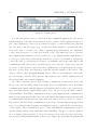
In manufacturing industry but not only limited to it, the production speed is critical
in order to achieve desired profit for the companies. The production itself is usually
controled by an industrial computer or PLC and the motion itself is caried on by simple
single-axis drives or more complex multi-axis drives. Usually multiple drives need to act
in some kind of synchronized manner in order to create the whole product. But as the
production speed is still increased, the quality of the product could decrease, because
little inaccuracies in synchronization that were permisible at lower speeds are beginning
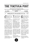
to turn into significant inaccuracies at higher speeds. A good example of such a process
where production speed is critical and has a direct impact on the profit is a newspaper
printing. Printing press is capable of printing about 10 pages per second which yields
in paper speed about 3 meters per second. There are several stages connected in series
that compose the printing press. First there is storage for a long paper sheet, which
is fed through high speed rollers further into machine. Then there is a series of rollers
touching each other that transfers the ink from the so called plate onto the paper (hence
the method is called the offset printing). This part is repeated 4 times, once for each
basic color and once for black (even though black could be mixed from basic color, it
is cheaper to have a black color separated). Then the paper is folded and chopped to
create the product. All the drives moving the rollers and other parts must be tightly
synchronized to produce the newspaper at such a speed. The synchronization has to be
in order of few miliseconds or submiliseconds since during 1ms the sheet could be 3mm
out of position, which could lead into a blurred image.
1
2
CHAPTER 1. INTRODUCTION
Figure 1.1: Printing Press
For fast and precise motion control in today’s industrial applications, the precise
synchronization of the drives is necessary in order to achieve desired quality and speed of
the control application. Since it is not always possible to connect all the drives directly
into the same controller device (e.g. because the drives might be operating far away
from each other or because of too much computational requirements), the distributed
control network needs to be developed in such a case. The usual way, how to decrease
the computational demands for devices and how to cope with placement requirements, is
to develop a device, that would run the fast closed control loop and that would directly
control the drive (or few drives) according to its dynamics and at the same time would
communicate with other devices and with the process controller. As process controller
we refer to controller that controls the whole industrial process and thus needs to know
the state of each device and in turn provides the reference inputs for the devices. The
devices could be called IO (Input-Output) devices. They act as an interface between the
process and the controller. They measure important process variables (Input) and feed
the system with control signals (Output).
As could be already foreseen, fast, real-time communication between the device and
the process controller (and possibly between the devices as well) must be used. Real-Time
communication ensures that the input process variables that are sent to the controller are
up-to-date and that the output signals will be fed to the process in some kind of timely,
reliable manner. Real-Time communication alone doesn’t imply that the communication
must be fast. It means that there are some well defined time limits in which the data will
be transfered through the network. Since this work aims to develop a device for controlling a drives, fast Real-Time communication is necessary. Another important aspect that
has to be considered when designing an industrial network or network devices is the price
of the cabling. The communication protocol that will fulfill the requirements for speed
and its cabling is cheap at the same time is the PROFInet. The protocol will be desribed
more in chapter (Dat referenci). To allow easy incorporation of the developed device into
the already working industrial plant, behavior according some well defined standards will
3
be helpful. The standard for motion control built on top of the PROFInet stack is called
PROFIdrive profile and this standard will be implemented in the device. Since the whole
PROFIdrive profile is a huge system with great variability in the sense of used drives,
implement whole profile would be too demanding. Only the neccessary part of the profile,
directly related to our particular drive will be implemented. But since the main mechanism is needed for that, adding the support for broader range of drives will be simplier.
The content of this document is divided as follows. In chapter II (Reference) will be
presented hardware and software configuration that will be used and will be given some
theoretical background about PROFInet in order to justify it’s choice as communication
protocol for our device. The theory will as well bring more light into some implementation
details described later so that they will be understandable to the reader in the scope of
the whole application. In chapter III (Reference) will be provided implementation details
and their role in overall functionality. Some areas in this chapter might be described
step by step in order to allow reader to replicate the developed device functionality. In
chapter IV (Reference) will be described the testbed for testing the functionality of the
device. In chapter V (Reference) will be given conclusion and summary of achieved goals
as well as contemplation about possible changes in the future.
4
CHAPTER 1. INTRODUCTION
Chapter 2
System Description
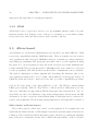
In this chapter will be described our system. In first section a general overview of the
system will be provided from both software and hardware perspective.In the next section
used communicaiton protocol will be described and will be compared to some other possibilities. That should provide neccessary information in order to understand the desired
device functionality. In the next section will be described used hardware configuration,
including the drive, the IO device and its interface towards the drive,towards the users
and towards the process controller. In the last section used software, including source
code, and toolchain will be described. The particular importance in describing the source
code will have the interfaces between various parts of the application.
2.1
System overview
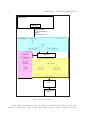
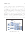
In this section we will describe the designed system as a whole and try to show the
relations between individual devices and their subsystems. Let us start with the schema
of the system shown on the following figure.
5
6
CHAPTER 2. SYSTEM DESCRIPTION
PN Controller
Process Control
Application
Cyclic (IO data)
Acyclic (Parameters)
Alarms
Clock Synchronous
PN IO Device
PN Interface
SDAI
SDAI Callbacks
SDAI Functions
PROFIdrive
PD Parameter
Manager
Application
PXMC Functions
Cyclic interrupt service
PD Object
Dictionary
PD Axis
Control
PXMC Library
VHDL Quadr
Encoder
VHDL PWM
Generator
Motor Interface
Motor Adaptation
Circuit
3Phase Brushless
Motor
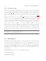
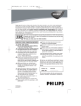
Figure 2.1: Overall schema
On the figure the hardware parts as well as software parts are shown. As for the
hardware components of the system, in working setup, it consist of system controller,
2.1. SYSTEM OVERVIEW
7
PROFInet IO device, motor adaptation circuit and a 3-phase brushless motor. In the
industry there will be typically one PROFInet system controller and multiple PROFInet
IO devices each with 1 or 2 motors connected.
2.1.1
System controller
There are actually two angles of view of how to describe the system controller.
First one is when we consider the functional part and the control logic of the system.
Then the system controller could be described as a device on which the main process
control logic is implemented. This device executes the main control loop in a sense of
processing the process input data, computing new state of the system and providing the
new output data for the actuators. From this point of view there is no difference whether
the inputs are connected directly to the controller or provided by remote devices and
whether the actuators are connected directly or located as well on the remote devices.
Second angle is to consider the device roles from the networking point of view. Then
we would describe the controller as a device capable of acting as a PROFInet master in the
PROFInet topology. The role of PROFInet master is to control the network data cycle
and in the case of Isochronous Real Time to provide the reference clock for other devices.
There are 3 devices capable of acting as a PROFInet controller that are considered in
our system. Each has it’s own qualities which are important in different part of IO device
development.
Simatic PROFInet controller
This standard PROFInet controller is used for basic connection to the IO device. It
is used in order to observe and investigate the communication establishment process between the IO device and the controller. Then the simple application on the controller
is run to observe the communication and IO data exchange. Another advantage of using the standard controller is not many restrictions and rules for connected IO devices.
Simotion controller
Simotion controller is PROFIdrive compliant PROFInet controller. This device is
used in combination with PROFIdrive aware and compliant IO devices. On top of the
PROFIdrive communication it provides the advanced tools for motion control. For example trajectory interpolation. It can be used to test and run PROFIdrive applications as a
8
CHAPTER 2. SYSTEM DESCRIPTION
whole.
PROFIdrive Tester
PROFIdrive Tester is an PC application in combination with the special network
interface card. The device then acts in PROFInet network as standard controller and
the same set of tools for programming the Simatic controller can be used. It could be
used to test whether the IO device PROFIdrive features are implemented according to
PROFIdrive profile specifications. The advantege is that individual features can be tested
independently and with no need for an running application.
2.1.2
PROFInet IO device
PROFInet IO device is peripheral device to the PROFInet controller. It is capable of
sensing the process data and/or control the actuators/process directly. It reads the output
data provided through the network by the controller and it provides the Input data to the
controller. There are different reasons and situations where it is advantageous or necessary
to use IO device instead of connecting the inputs and outputs to the controller directly.
Localization
In a large processes taking place over the large area, it is necessary to read the data
close to the system that generated them. Over the large distance a signal containing the
data could get polluted by electromagnetic noise from the environment. Reading the signal close to the source and transfering it into some data representation reduces the impact
of the noise to the signal. It can reduce the cabling costs as well since there will be only one
cable from the IO device to the controller while for the raw signal there might be needed
more
cabling.
Computational complexity
Process control can be computationaly complex task. For example computing the
ideal trajectories for series of motors, reacting to the feedback and adjusting the values accordingly, implementing some advanced feedback control that requires a lot of
memory and processing and so on. It might be then desirable to move some computation from the central controller into the peripheral devices. The tasks that peripheral IO devices perform usually include some initial Input signal processing (filtering, averaging, scaling, decoding) or some Output signal processing (PWM, scaling).
9
2.1. SYSTEM OVERVIEW
Logical decomposition
Developing and maitaining more smaller parts of the application all with its own purpose can be easier than mantaining one central application that takes care for everything
from converting inputs and outputs to some meaningful values to maintaining internal
states
of
application.
We will now briefly describe the subsystems of the IO Device while their implementation and functionality will be described in detail in later chapters.
2.1.2.1
PROFInet Stack
PROFInet stack is a subsystem of the application, that takes care of networking. In our
particular case it allows the device to act as a PROFInet slave device in a PROFInet
network, handles the incoming and outgoing messageses and provides the means for the
application to create or read message content to some extent. In terms of ISO/OSI model,
it provides hardware and software components to control the first two/three layers and
provide the programming tools or interface to the networking services for the application.
While for non real-time communication, standard ethernet network interface hardware
would be sufficient, for real-time PROFInet modes, the ethernet switch has to be adjusted
to provide all the services.
2.1.2.2
PROFIdrive Stack
PROFIdrive stack is set of software components that implement PROFIdrive profile on
top of the PROFInet stack. Profile uses PROFInet services and doesn’t require any
changes to the PROFInet stack if all the networking services are available. It defines
certain rules, procedures, module types, alarms and state machines that are typical for
the most of the motion control applications and provides a the instructions on how to
implement them with PROFInet. It can be used with other PROFIdrive IO devices or
controllers.
2.1.2.3
Main Application
As the main application we call a part of our program where the ”main” loop is running. It actually connects all the other applicaiton subsystems together(PROFInet stack,
PROFIdrive stack, motion control) and takes care of propper initialization of each part. It
10
CHAPTER 2. SYSTEM DESCRIPTION
is the application part that is notified about the external events (either through hardware
or stack callbacks) and uses the services provided by modules. Our application initializes
the PROFInet stack, PXMC library for motion control and listens on a callback methods
from PROFInet API and has an access to PXMC data and PXMC functions to change
the drive behavior. It also handles the hardware events from the Altera board.
2.1.2.4
Motion Control
Motion control subsystem takes care of converting the control data provided by the main
application into signals that are fed directly to the drives. On the other hand it handles
converting the raw signal provided by the sensors on the drives into some meaningful
representation for the main applications. It is composed of 3 parts from which one is
PXMC-Portable highly eXtendable Motion Control library. That is a software component
that handles the internal state machine for the motion control and keeps track of motor
state, provides services for computation of speed and position and on the other hand
provides methods to control motor state. It allows programmer to implement some
basic feedback controller. In our case PID controller is used. The other part is a Pulse
Width Modulator, implemented as a FPGA block, that translates the control voltage
into to PWM signal fed into the drive. Last importantant part is Quadratic decoder that
converts signal from quadratic encoder into the pulse counter, that is in the end used for
determining the speed and position of the drive.
2.1.3
Motor and adaptation circuit
Motor and adaptation circuit is the part of the system that directly controls the process.
Motor is connected via the adaptation circuit into the IO device board. Adaptation circuit
solves the power requirements of the drive that cannot be supplied from the boards, it
provides the galvanic isolation of control signal and power signal and it allows the board
to disable any of 3 3-phase control PWMs.
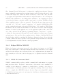
Chapter 3
Components and Technologies Used
In this chapter we will describe what particular hardware and software was used for our
device. What particular software components, what tools and why were they chosen for
our implementation. We will provide more theoretical overview of the system components
in this chapter and in the following chapter we will describe the implementation process
in the detail. This chapter should provide necessary initial knowledge to understand used
components, their capabilities and to make reader familiar with the technology used. This
allow us to follow up with the implementation details and focus on the implementation
without the need to describe the technology and tools in between technological details.
3.1
Communication Protocol - PROFInet
Select the right communication protocol for the device is important decision and has to
be made at the beginning of the design. According to the selected protocol, the hardware
with
sufficient
peripherals
3.1.1
Industrial Ethernet
and
performance
can
be
chosen.
Over the last years, Industrial Ethernet is increasing its popularity as a protocol of
choice for process industries. It is estimated that about 45% of all the nodes connected
in process industries is communicating via Industrial Ethernet. Ethernet is widely used
in offices and households, more than 85% of LAN connected devices uses Ethernet [1].
11
12
CHAPTER 3. COMPONENTS AND TECHNOLOGIES USED
This widespread of Ethernet actually increases the ethernet technology development and
therefore makes it more affordable and suitable to various environments, including industrial environment. Using ethernet for industrial processes also allows for seamless
information integration from field control layer to management layer. The advantages of
Industrial Ethernet against other protocols often used in field control layer is it’s high
data transfer rate, high reliability, easy to maintenance and quite long range availability [2]. It is also possible to use traditional office network elements like routers and
switches if no special requirements like deterministic communication are required. The
disandvantages of ethernet are that it’s not naturally reliable and real-time protocol so
if it is needed, the upper protocol layers need to provide those features. Another adjustments that usually needs to be made for industrial ethernet are related to the harsh
environment the devices are in. Therefore the connectors, cables and switches are usually
rugged and can resist higher temperatures. Ethernet cabling has naturally pretty good
resistance against electromagnetic disturbances, which is important in industrial environments. Using ethernet switches also allows to separate sets of devices into domains
called sub-networks. It allows for better logical division, for separation of the data flow
from another parts of the network, eg. the devices in subnet manage their own rules for
access to shared resources and does not need to care about the rest of the whole network.
For our project we chose PROFInet as a communicaiton protocol. It provides the
needed functionality in terms of available real-time modes to be able to transfer data
between IO devices and process controller in reasonable low time, that is critical for controling tightly synchronized drives. At the same time, PROFInet belongs to the family of
Industrial Ethernet protocols. That means, that for physical and link layer (according to
ISO/OSI model) could be used the same hardware and the same cabling as for Ethernet.
On top of that, expansion to the PROFInet called PROFIdrive profile provides a set of
rules and description of the interfaces between PROFIdrive conformant devices and controller and therefore stands for the standard for motion control in PROFInet-based network.
PROFInet distingueshes between 3 device types. Those are [23]:
Controller is a PROFInet master device that provides desired output data for devices
and receives from them the input data (cyclic data). It also exchanges acyclic data
with devices.
13
3.1. COMMUNICATION PROTOCOL - PROFINET
Device is a PROFInet slave device in the field that reads inputs and writes outputs to
the controlled process. It exchanges cyclic and acyclic data with controller.
Supervisor is a machine used for configuration and monitoring of the process.
”PROFInet devices are based on a modular device model” [19]. That means that device
can be equiped with various modules, which are plugged into device slots, most of them
usually being I/O modules. Particulary important module is DAP-Device Access Point.
That is module that represents the network interface of the device. Slots can be further
divided into submodules. While modules can represent either real physical device or virtual device, submodules has no physical counterpart and represent only virtual division.
Data interpretation
3.1.2
PROFInet RT/IRT
PROFInet Real-Time modes ensure that IO data are always exchanged in defined time
intervals. This is achieved by diving the available bandwith between real-time cyclic
communication and non real-time acyclic communication. Cyclic data are transfered
with preference over acyclic data using RT/IRT channel. When there is still available
bandwith, then the acyclic data are transfered.
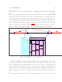
3.1.2.1
Cyclic data exchange
IO data are exchanged between devices as a cyclic data. The base period for cyclic data
exchange is called SendClock which is 31.25µs long and is divided into phases. SendClockFactor is integer defining multiple of SendClocks that compose a network SendCycle.
Although it can get more complicated in particular scenarios, the basic division is to Red
phase and Green phase. More precise division would be important if we were to develop
the PROFInet stack, for users, using PROFInet stack services, this division is sufficient.
Red
In
phase
the
red
phase
all
IO
data
are
transmited
between
devices.
Red phase is defined so that maximum lenght must leave leftover for the Green period so
that
• Must allow transmision of non-fragmentable frames
• Must allow transmision of at least one such a frame
[18]
14
CHAPTER 3. COMPONENTS AND TECHNOLOGIES USED
• Cannot exceed MaxRedPeriodLength defined in GSD metadata
Each IRT device has to know when exactly red period starts and when it ends. Device calculates it for both Rx and Tx directions. Red phase always begins at start
of the SendClock period.
Red phase ends when the last IRT frame is transmited.
Green
phase
As described in red phase definition, green phase length is a leftover in SendClock period
after all IRT frames has been transmitted. Data transmission uses standard UDP/IP
protocol.
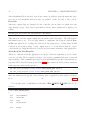
3.1.2.2
Acyclic data exchange
Acyclic data exchange is used for sending all other data than IO. Those contain configuration
and
diagnostic
information,
alarms
and
parameter
record
Parameter Record Data
• Write Request
• Write Response
• Read Request
• Read Response
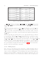
Example of SendCycle for SendClockF actor = 2 can be seen on the figure 3.1.
Figure 3.1: SendCycle example
data.
15
3.1. COMMUNICATION PROTOCOL - PROFINET
3.1.3
GSDML
Slot and subslot data exchange is in general done as an exchange of bytes between the
devices. GSDML file stands for General Station Description Markup Language [9]. It is
a XML based device description that supports device description according to PROFInet
device
model
mentioned
in
[19][23].
Element top level topology will be now described with emphasis on elements that will
be used in our device description. All the module specific elements will be described for
better readability later.
• ISO15745Profile is the root element of GSDML file.
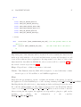
– ProfileHeader Header must always look like (REF fig gsdml header).
– ProfileBody Includes main parts of device description.
∗ DeviceIdentity Attributes are VendorID and DeviceID.
· InfoText
· VendorName
∗ DeviceFunction
· Family Contains vendor information about what family of devices
this device belongs to.
∗ ApplicationProcess Contains all the information about device modules.
ApplicationProcess
This is the parent element for all the module specific information. This includes module
I/O type, usable slots and subslots, general list of modules and DAP modules. it’s structure will be now described. Not all the elements will be described, only those with some
siginificance in our application. Whole specification can be found in [9].
• DeviceAccessPointList List of DAP modules.
– DeviceAccessPointItem Describes 1 DAP module. With attributes ID,
PhysicalSlots-telling in which slots the module can be inserted and ModuleIdentNumber -the number that is used in exchanged data to identify the module.
∗ ModuleInfo
· Name
· InfoText
16
CHAPTER 3. COMPONENTS AND TECHNOLOGIES USED
· VendorName
· HardwareRelease
· SoftwareRelease
∗ CertificationInfo Information about certification.
∗ SubslotList List of subslots of the module.
· SubslotItem Contains attributes SubslotNumber and TextId.
∗ IOConfigData Contains attributes like MaxInputLength, MaxOutputLength meaning the maximum IO data in octets (CITE GSDML). This is
the sum of all the data that can be exchanged by submodules.
∗ UsableModules List of references to the modules described in GSDML
that can be used with this DAP.
· ModuleItemRef With attributes ModuleItemTarget and AllowedInSlotstelling in which slots the modules can be used.
• ModuleList Contains list of all modules, not all need to be used by application.
– ModuleItem Describes 1 module available in the device with attributes ID
and ModuleIdentNumber -number that is used by application and sent by network. Must match the number assigned in application.
∗ ModuleInfo With attribute CategoryRef -telling from which category of
modules the module is (e.g. Input Module, Output Module ...)
· Name
· InfoText
· OrderNumber
· HarwareRelease
· SoftwareRelease
∗ VirtualSubmoduleList Contains virtual submodules available for each
module. Since submodules aren’t physical devices, all the submodules
available for the device are listed here.
· VirtualSubmoduleItem Contains attributes like VirtualSubmoduleNumber -which must much the number assigned by the application
in the device and API -meaning Application Process Identifier in this
context. Defines to which process VirtualSubmoduleItem belongs. For
3.1. COMMUNICATION PROTOCOL - PROFINET
17
example PROFIdrive has its own API number defined. Users can define their API to distinguish for which process the modules is supposed
to be used.
Again for better readability the most important element for IO data exchange VirtualSubmoduleItem will be described in more detail:
• IOData Contains attributes IOPS Length-IO Producer Status and IOCS LengthIO Consumer Status. Both those lengths cannot exceed 1440 octets (CITE GSDML). Child elements contain information about particular input and output data
that the submodule can exchange through network.
– Input Containing child important child element DataItem that contains particular data information like DataType-e.g. unsinged8, float32 describing the
data representation and UseAsBits flag, telling the engineering tool that the
data should be displayed/represented as individual bits, not being translated
to for example decimal number.
– Output Contains similiar information as Input but for Output module
– InputOutput The bits of this VirtualSubmoduleItem can be represented as
both input or output.
• RecordDataList Contains list of ParameterRecordDataItem
• ModuleInfo
On the next figure is the standard ProfileHeader used in GSDML v2.31.
Figure 3.2: GSDML Header
18
CHAPTER 3. COMPONENTS AND TECHNOLOGIES USED
3.2
PROFInet Stack
”Softing Protocol IP for PROFINET is a combination of IP cores and Industrial Ethernet
device protocol software designed to offer all required communication capabilities for an
implementation based on the Altera FPGA.” [19] There can be used various industrial
communication protocol with the stack while all use the same programming API called
SDAI-Simple
Device
Aplication
Interface.
According to documentation [3][19] it can be used for:
• Verify the functionality of available protocols.
• To learn about the protocol integration.
• To integrate the protocol into field devices.
• To work as a PROFInet, PROFInet RT/IRT device.
The package contains:
• Documentation
• IP core license
• Real time ethernet switch IP core
• Other utility IP cores
• NIOS II project and source code
• NIOS II software project
• NIOS II demo application
• SDAI code and documentation
There is a 2 hour evaluation period timer, which block the functionality after the timer
expires. This is for the users to test the functionality without buying the product. After
purchase the timer is disabled. For our development we were using this evaluation feature.
According to [19] the stack is compliant with PROFInet version 2.3, GSDML version 2.31
and PROFIdrive version 4.1.
19
3.2. PROFINET STACK
3.2.1
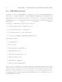
Hardware Components
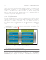
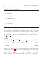
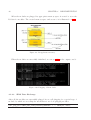
In this section we will describe hardware components used in the FPGA design. An
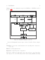
overview of the components and their interconnection is on the 3.3
MM-Bridge
IRQ-PIO
MM-Bridge
Remote
Update
SysId
Flash
Controller
MM-Bridge
Reset-Bridge
RAM
Controller
Reset-Bridge
MM-Bridge
MM-Bridge
IRQ-PIO
Mutex
NIOS II
NIOS II
DPRAM
Timer
Reset-PIO
Peripherals(LED,
LCD, pushbuttons)
Clock-Bridge
RTE Switch
Timer
PLL
Figure 3.3: FPGA hardware components
”The IE subsystem (Switch subsystem) contains the switch IP core from Softing and
the Nios II core. The Nios II uses a MM Bridge to access Flash and RAM. The memory provided is transparent for the Nios II. It has to be implemented outside of the
subcomponent. Interaction with the Application subsystem is implemented via a DP
RAM in the IE subsystem. Mutex and IRQ are used to control access to the DP RAM.
The second subcomponent is the Application subsystem. It contains a Nios II on which
the sample application runs. Furthermore various IP cores to interact with the peripherals
are
part
of
this
subcomponent”
[19].
For users of the stack the most important is the Application subsystem. That is because unlike RT Switch subsystem, the application subsystem is accessible to user via
standart Altera FPGA tools and can therefore make modifications in the application subsystem. RT Switch subsystem is unaccessible to the user and is provided as and IP core.
We will be making some modifications in order to connect the motors and to allow some
MM-Bridge
20
CHAPTER 3. COMPONENTS AND TECHNOLOGIES USED
supervision through Altera board physical interface.
3.2.2
SDAI
SDAI-Simple Device Application Interface is a programming interface built on top the
hardware system. It is desinged for use of the protocol features, to create initial configuration and receive and send data between device and the controller.
3.3
Altera board
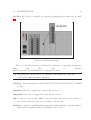
As a hardware for our IO device implementation we decided to use Altera DE2-115. Main
reason was compatibility with the PROFInet stack. There is actually very few vendors
and organisations that developed PROFInet stack as a standalone software/hardware
and defined programming API, giving the users full control over the application using
the stack. For our development we used the stack developed by Softing Industrial Automation GmbH. They provide the stack for PROFInet slave device with a lot of freedom
for the programmer and with Isochronous Real Time communication mode available.
The stack is distributed as Altera Quartus files describing the hardware and a software application written in C on top of that. Altera DE2-115 is amongs the devices on
which the stack was tested so there was lower risk of possible compatibility problems.
Cyclone IV is the heart of the Altera DE2-115 board. The FPGA contains 114480
LEs(Logical elements, LUTs-LookUp Tables or Slices) and 439 M9K memory blocks.
Those two attributes are important in FPGA design since they represent how ”big” design can fit onto the board. Hardware components and their interconnections use the LEs
and memory blocks to create the desired functionality. FPGA pins can be connected directly to the peripherals. The most important peripherals in our design will be described.
Slide switches and Push buttons
Those will be used for direct user control over the application. For example they can
switch the information shown on LCD display between the stack information and drive information. They can directly disable the signal going to the drive by exciting the disabling
pins on the motor adaptation circuit. Motor disable through switches on the board have
21
3.4. ALTERA TOOLS
actually priority over the software wanting to enable it. They can be as well used to control
the
speed
of
the
drive.
LCD display and LED diodes
Are used to display various information for the user. We use it to display PROFInet
stack
state,
motor
state
and
values
fed
into
the
motor.
GPIO
GPIO pins on the board are General Peripheral IO pins allowing the FPGA to drive
the singal out of the board. We use those to control the motor. There are 2 connectors
available for that purpose. Both allowing the user to chose the High level between 2.5V,
3.3V or 5V. The GPIO connector provides as well the ground and limited power supply
with 5V voltage and up to a 1A current [14].
3.4
Altera tools
As a development environment we have chosen a toolchain from Altera providing a tools
for graphical hardware design, hardware and software programming environment and
compilation, build and deployment tools to load the application onto the board. It is
possible to develop an application without those tools, using only compilers for Alteras
FPGAs, but the toolchain is a kind of waranty that application developed with Altera
toolchain will run on Altera FPGA. Another important argument to use Altera toolchain
is that a lot of PROFInet stack components is available as a file to be used with Altera
toolchain and then we can modify or observe the design with those tools.
3.4.1
Quartus II
Quartus II is a software for designing and compiling an FPGA design. It allows smooth
integration of 3rd party IP cores and design and validation of the FPGA components on
various levels, for example meeting timing constraints, whether the design can fit into
the FPGA, allows to easily create and interconnect IP cores with Qsys builder tool. This
tool is important when designing a processor, network switch and peripherals into the
FPGA, therefore we will use this tool a lot. Then it provides a basic editor for VHDL
22
CHAPTER 3. COMPONENTS AND TECHNOLOGIES USED
files. Quartus II as well allows users to configure the compilation preferences. Between
many configurable parameters the most important is tradeoff between the speed of the
circuits and designs size. When the FPGA is driven by a fast clock source, the time
to propagate the signal in the circuit cannot be neglected anymore. For our design we
instructed the synthetizer to use timing-driven synthesis so the emphasis was placed
on meeting the timing constraints, which is important for real-time PROFInet switch.
After compilation many of files are generated. From the the most imporant are the
ones with ”.sof”, ”.jdi” and ”.sopcinfo” extensions. ”.sof” stands for SRAM Object File
and it contains the information about the FPGA design. ”.jdi” stands for JTAG Debug
Information and it contains the information for the device about the JTAG debugging
interface. It is used by the application to see the application print on the console window of the connected PC through the programming interface of the device. ”.sopcinfo”
contains the Qsys generated information about the application address space, settings
and preferences. It is used by other compliers in the toolchain to build the BSP-Board
Specific Package which is something like Hardware Abstraction Layer. It provides the
constant, defines and macros specific for the particular design and therefore hides the
board implementation details from the software programmer.
3.4.2
Eclipse IDE for NIOS II
Eclipse development environment was used for the software development onto the NIOS
II processor, that is part of our design. Except text editor it provides the tools to compile
and dowload the design to the board and see the console output and write the input. We
used it mainly as a text editor and for the purposes of compilation used the command
shell.
3.4.3
NIOS II Command Shell
NIOS II command shell provides posix-like command shell environment for programming the altera device. It allows to run various tools from the console terminal. For
example ”nios2-configure-sof” command to download the .sof desing to the device or
”nios2-terminal” to watch the printouts of the application running on the board. It also
allows to compile whole HW/SW desing for the nios II processor using GCC compiler
for NIOS. For the latest version of our design, the 14.0 Altera toolchain was used, which
comes with version 4.5.3.
23
3.4. ALTERA TOOLS
3.4.4
NIOS II Processor
Software part of our application - written in C - will be running on the NIOS II soft
processor implemented on the FPGA (CITE NIOS II software developer’s handbook,
NII exception handling, NII cpu manual). Since there is a thin line between what is
processed in hardware and what in software, it is important to understand capabilities of NIOS II processor and to be able to adjust it’s functionality when necessary.
NIOS II is a general-purpose RISC processor [8] with 32-bit instruction set, registers and
address space. Between important features belongs 32 interrupt sources, access to variety on chip peripherals, hardware-assisted debug module, software development based
on GNU C/C++ toolchain, interfaces to on-chip and off-chip memory. User can decide
what features the processor will implement and therefore customize it to his needs. For
example NIOS II offers floating point arithmetic instructions, but for the cost of additional resources. User can decide what side of trade-off to take, wheter the speed is
more important than resource usage or the other way around. Then the functionality
can be implemented directly by the processor, emulated in software or omitted entirely.
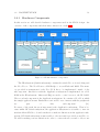
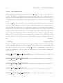
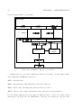
On the next figure we can se the interconnections between the processor and peripherals.
Figure 3.4: Altera interconnection schema
NIOS II offers to customize the processor core attributes (such as speed, creat-
24
CHAPTER 3. COMPONENTS AND TECHNOLOGIES USED
ing custom registers, ...) and allows to easy interconnect the processor with standard
peripherals such as SDRAM, general puprose I/O, ethernet interface, debug module
and with custom peripherals or hardware blocks(We will later connect the processor
to motion control hardware blocks, in order to reduce processor load and to achieve
high enough speed) as well. Access to peripherals is implemented by memory mapping of peripherals to the data bus address space.
Registers can be configured to
support single-bit write/read operations as well as full byte write/read (by default).
NIOS II processor provides simple non-vectored exception controller. When an interrupt
occurs, exception controller controller passes the control to appropriate exception handler
[8]. This functionality will be used to invoke motion control library in regular short intervals. Generated board support package and hardware abstraction layer provides the the
software with methods to define timers that trigger processor interrupt and methods to
define respective exception handlers. NIOS II Internal Interrupt controller can distinguish
between 32 interrupt requests. Interrupt requests can be disabled/enabled by modifying
the processors control registers. This can be done at runtime and will be important for our
application.
NIOS II supports separate data and instruction space, there classifying it as Hardware architecture [8]. Instruction and data busses are implemented as Avalon-Memory Mapped
master ports. While the data master port connects to both memory and peripheral
components, instruction master port connects only to memory.
3.5
PXMC
PXMC is a software library project for motion control. It is a multi platform code
designed to be easily run on different platforms and with different motors [16]. There
is actually one flaw to the portability and that is that there must exist C/C++ compiler for target platform. It is software library and a system core, meaning it has some
strict requirments on some services provided by hardware that must be met for flawless
operation. Those requirments include execption handling, operation atomicity and availability of some hardware components. Particular requirements will be described later.
Variants of the code have been succesfully used on many targets for robotics, laboratory
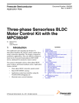
and medical projects [24]. On the following figure we can see PXMC data flow schematic.
Chapter 4
Implementation
In this chapter we will describe how the implementation was done. At first we will
described the protocol in 4.1. What is the provided files structure, what is and what
is not part of the PROFInet stack. We will describe how we deployed the application on the device, what changes have been made and how the design was verified.
Next we will describe how the PXMC was adjusted in order to be ported onto NIOS II architecture in section 4.2. What files have been used, what important functions and object
PXMC provides, what hardware adjustment needed to be done and how the motor is connected
to
the
device.
After that we describe obtained PROFIdrive stack implementation and it’s integration
into our device in order to create PROFIdrive IRT application. This process is described
in
4.4.2.
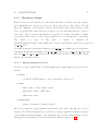
Before diving deep into implementation details we will remind what is the planned functionality of the device on the figure 4.1. Most important parts of the implementation are
as well described in 2.1
25
26
CHAPTER 4. IMPLEMENTATION
Figure 4.1: Top level functionality
4.1
PROFInet stack
As already mentioned in 3.2, PROFInet stack includes both hardware and software desing.
For non real-time communication, standard ethernet switch could be used, but real-time
modes require some functionality on the hardware side because of strict timing requirements.
Hardware is distributed as a Quartus II project and a set of IP core files and licences that
are needed for succesfull compilation of hardware design. The files contained in the distribution, process of hardware design and compilation and important generated files will be
described
in
4.1.1.
When the hardware is compiled and all the necessary files generated, software development can start (actually it can start independently when the interface is well known in advance). In section 4.1.2 will be described the software files used for the C application, important
methods,
design
features
and
objects.
27
4.1. PROFINET STACK
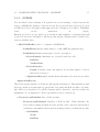
4.1.1
Hardware design
In this section we will describe how the initial hardware looks like and what changes
and adjustments were made, how they were made and what do they affect. We will
put some emphasis on the interface between the hardware and software design. That
is set of generated files called BSP-Board Support Package and HAL-Hardware Abstraction Layer. Those software subsystems are created as a result of hardware compilation and provides a layer for the software application to access hardware components.
The
main
tool
used
in
this
part
of
design
is
Quartus
II.
Obtained hardware design for Altera DE2-115 board is located under hardware/fpga/profinet/altera ink switch/.
Most important files for hardware design are altera ink pn.vhd which is top level hardware
description file and three Qsys files altera ink appl subsystem.qsys, qsys profinet system.qsys
and softing profinet device subsystem.qsys. First it was necessary to add motor related
IOs into the hardware design.
4.1.1.1
Inputs/Outputs for motor
For motion control with PXMC, following inputs and outputs must be provided by the
system:
• Output
– 3x PWM - PWM signal to control each phase of the motor
• Input
– IRC counter - Value of IRC counter
– IRC index - Value of IRC index
– HAL sensor value
• InputOutput
– Status - Contains e.g. Enable/Disable
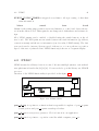
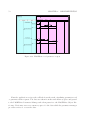
Those were added into Qsys application subsystem and ”wired” through the top level
system to the memory-mapped area accessible by software application. Memory address
in the NIOS II system is relative to the subsystem. We chose free address range between
0x00000 010 and 0x00000 070. Created IO and their wiring is shown on 4.2.
28
CHAPTER 4. IMPLEMENTATION
Figure 4.2: Qsys application subsystem IO
pio axis0 hal defined as 3-bit input, pio axis0 irc cnt and pio axis0 irc index as 32-bit
inputs, pio axis0 irc status as 8-bit bidirectional signal and pio axis0 pwm(1,2,3) as 16-bit
output.
Signal clk clock is being connected to master clk system clk signal, reset to the clk system
clk reset signal and s1 to the cpu data master port. By setting the Conduit to external connection value, we mean that the signal will be read/written outside of the subsystem. In this case we need first to export the signal from the application subsystem into
qsys system.
When the Qsys files gets generated, there are two important files that we will need
to locate and use. First is qsys profinet system.qip that needs to be added as a source
file in the quartus project in order to compile the project right. The other one being
qsys profine system inst.vhd containig vhdl component description of the qsys profinet system.
In this file we need to find the names which have been assigned to our new signals in
order to use them in top level vhdl file. How the components are connected together in
the top level hardware description file will be described in 4.1.1.4. It is necessary first to
introduce other developed hardware components.
4.1.1.2
PWM generator
Since our motion control library provides only means to compute the numeric value for
the motor and since software interrupt periods cannot achieve short enough time, it is necessary to develop a PWM generator block in hardware and connect it between memorymapped area used by PXMC for output data and real physical output pins of the board.
PWM generator hardware block is block that takes a numeric value as an input (can be
29
4.1. PROFINET STACK
absolute or scaled) and outputs a signal that oscilates between High and Low levels. The
oscilation must be fast enough compared to the system that receives the signal in order
for the receiver of the PWM not to react to individal signal changes. The effect is that
slower system is capable of sensing only mean value of the signal, not reacting to individual
pulses.
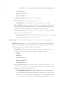
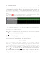
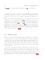
On the figure 4.3 can be seen simulation results for our vhdl pwm generator. All the
input and output ports and internal signals will be described then.
Figure 4.3: Modelsim pwm simulation
From the input/output point of view, the entity pwm generator was designed with
clk - Input port for 50MHz clock signal.
duty cycle - 15-bit input signal controlling pwm duty cycle. We decided to accept values
between 0 and 1000 (000001111101000).
pwm out - Output pwm signal.
It is important to design PWM generator to achieve a compromise between the frequency
and resolution of the output pwm signal. The rule that applies is
fclock = fpwm ṙpwm
where fclock is frequency of the driving clock signal, fpwm is a frequency of the pwm
signal and rpwm represents the number of descrete pwm output levels. There is a tradeoff between pwm frequency and pwm granularity. The higher the frequency of pwm
signal is, the lower is the granularity of the signal and vice versa. For example if
1
fpwm =
fclock we can achive only 100 pwm levels with range between output sig100
1
(HIGH − LOW ). Therefore we must choose
nal LOW and HIGH and granularity
100
the values in order for pwm signal to be ”fast enough” compared to the motor and
with granularity being lower than the required lowest speed step. For example if our
30
CHAPTER 4. IMPLEMENTATION
motor is running with speedmax = 1000 revolutions per second with 24V driving signal and we want the precision of the set speed to be at least step = 0.1 revolutions
1000
speedmax
=
= 10000 levels.
per second, than our PWM has to support at least
step
0.1
In our design we decided that reasonable pwm frequency is 50KHz leaving the PWM
granularity to be 1000 levels. Hence the input duty cycle is required to be 0-1000.
On the 4.3 we can see that with duty cycle = 256, the pwm out duty cycle is approximately 25%.
4.1.1.3
Quadrature Counter
IRC decoder is a hardware block that takes IRC quadrature encoder signals as an input
and outputs a single value representing the absolute position of the motor. Signals that
are received from the encoder are Channel A, Channel B and Index channel. Signals
comming from Channel A and Channel B are pulses shifted by 90 deg to each other.
Edge detection is used to count the changes and phase shift allows to determine the
way of the rotation. Combination of rising/falling edge of either channel and respective
LOW/HIGH value of the other channel then uniquelly identifies whether to increment or
decrement the counter. If channel A leads channel B, then the counter is incremented,
if channel B leads then the counter is decremented. Index channel pulse signals 1 full
rotation of the motor. There are 3 modes how the quadratic counter signal can be decoded
X1 - Counter is changed only on falling or rising edge of one channel.
X2 - Counter is changed on both edges of one channel.
X4 - Counter is changed on both edges of both channels.
We
will
use
X4
mode
for
better
resolution
Input/Output ports of quad count are
clk
chan A in - Input Channel A from encoder.
chan B in - Input Channel B from encoder.
irc index in - Input Index channel.
cnt out - Output 32-bit counter value.
irc index out - Output 32-bit offset of index pulse to counter value.
of
position.
31
4.1. PROFINET STACK
irc index cnt out - Output 4-bit index counter value.
cnt ovrflw - Output pulse when counter wraps around.
cnt way - Output 1-”UP”, 2-”DOWN”
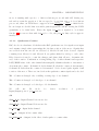
Simulation results of the designed quadrature counter for the positive increment are on
figure 4.4
Figure 4.4: Quadratic counter simulation
After testing the quad count hardware block in the design on the real motor, it turned
out that we need to solve some practical problems first because the value of the counter
started to drift away from the real position of the motor. That is because real physical encoders encounters problems like signal bouncing and also it was necessary to synchronize
the
timing
of
the
”outer
world”
with
the
FPGA
timing.
The first issue was solved by introducing the debounce filter hardware component in
between the quadrature encoder signals and quad count logic. The debounce filter logic
is to wait for some time after the edge is detected on the signal and output the new signal
only after the wait delay ends. This removes some possible counter miscalculation due
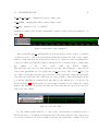
to bouncing. Simulation of designed debounce filter for the threshold of 5 clock period is
shown on figure 4.5. On the figure we can see that bouncing does not affect the output
signal of the hardware block and only after the delay when the level is steady is the new
value fed to the output.
Figure 4.5: Debounce filter
For the timing synchronization of ”outer world” and internal clock-driven world of
FPGA, the series of 3 D flip-flop circuits was used. It ensures that the value is preserved
for exactly 3 master clock periods until it gets into the quadrature counture logic and
32
CHAPTER 4. IMPLEMENTATION
therefore making it synchronized to the internal clock, instead of feeding the counter logic
with new data whenever they are available.
4.1.1.4
Complete Design
All the designed hardware components are put together in the top level vhdl file and portmapped to the right input/output ports of the top-level design 4.6 and/or to the ports
of qsys profinet system component as described in 4.1.1.1. As mentioned in 4.1.1, toplevel file for the vhdl hardware design is altera ink pn.vhd with the altera ink pn entity.
It’s input/output ports are meant to be assigned to the physical pins of the FPGA and
provides the access point between FPGA design and physical I/O.
Figure 4.6: Top-level IO for motion control
4.1.2
Software Application Design
In this section we will describe how the design application works and how the functionality
was evaluated. We will show the implementation in detail, provide the description of
the most important data structures and functions. Everything in this section revolves
around SDAI programming API which provides functions, processes and callbacks for
programmers to use the PROFInet stack in the device. It also implements necessary
data structures to send/receive the data through the network and to configure the device.
The initial application skeleton provided together with the stack is used, because it defines
some usefull data structures that simplyfies the coding and readability of the code. Most
important files used in the design are:
demo.c Initialization, main loop, callbacks and finalization.
4.1. PROFINET STACK
33
profinet.c Important data structures related to PROFInet are filled and defined here,
configuration functions are implemented here.
platform.c Board specific functions and interfaces are defined here such as writing to
LED display, reading button values.
pxmc nios ink.c Altera board specific PXMC, ported to NIOS II architecture.
It is important to note, that during implementation we encountered some bugs and
some functionality not being fully working so we had to actually implement everything
again from the scratch when the new version 1.20 of the stack was released, since it
implemented some features that are critical for our application. When speaking about
implementation, we will refer to implementation in the later 1.20 version but we will mention the features that are not working in the previous stack version on respective places.
Another note worth to mention is that application running on board configured with
JTAG debug module and connected to PC via USB can use terminal running on PC
for its standard input and output. To do this, host PC has to have USB Blaster driver
installed and then by running nios2terminal.exe command from the console, the console
starts to act as a terminal for the board. This was used for the debug of the board and
can be used as well for some runtime adjustments on the board.
4.1.2.1
Note about Debugging
SDAI comes with defined debugging macros that are defined in platform.h. There are 3
main debugging levels that could be used and can be enabled in the file:
Debug This macro is used as a highest debugging level. We use it in application to
notify about various events like callback calls, SDAI initialized ...
Error Use in application to notify about errors.
Trace This debug macro is used throughout the application to trace the call hierarchy.
We enhanced macros to display the file and the line of the print as well to make tracking
the bugs and problems easier. Trace can be used to track the call hierarchy deep into
the SDAI driver, but it is not recommended though. Because the nature of JTAG Debug
chain using JTAG UART is serial connection connecting stdin, stderr and stdout of device
to user console [8]. Serial connection with high traffic can be performance demanding
on the system resources. According to nios2 documentation ”the debug module gains
34
CHAPTER 4. IMPLEMENTATION
control of the processor either by asserting a hardware break signal, or by writing a break
instruction into program memory to be executed. In both cases, the processor transfers
execution to the routine located at the break address” [8]. Therefore debugging with
high rate of printouts can lead into application being slowed by the prints or (what we
observed) the output or the whole application freezes.
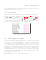
4.1.2.2
SDAI Initialization
Before the PROFInet Application Relation can be established between the device and the
controller, the device has to be configured first, which is programmed locally on the device.
Although there is possibility to tell the device to take some configuration from the controller during connection establishment, we went with aproach when the configuration is
coded
in
the
device.
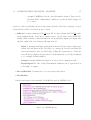
Initialization Let us first describe how the stack and SDAI are initialized. The
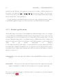
process is ilustrated on the figure 4.7.
Figure 4.7: SDAI and stack initialization
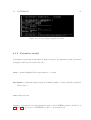
The initialization process is started by calling
U8 sdai_init (struct SDAI_INIT* pApplicationInitData)
Before we can do that, we must first assign some configuration data to the pApplicationInitData pointer. Mapping of the structure to the PROFInet IO is described in [3].
35
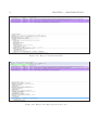
4.1. PROFINET STACK
The structure and its fields will be now described.
struct SDAI_INIT
{
U8
BackEnd;
U8
Alignment [3];
struct SDAI_IDENT_DATA Ident;
struct SDAI_DEVICE_DATA Info;
struct SDAI_CALLBACKS
Callback;
};
First we start with description of the SDAI CALLBACKS. This structure is filled with
functions to be called on various SDAI callbacks to notify the application about stack
events. The functionality of each callback is described in [3].
IdentDataCbk is called when the network parameter(e.g. ip address) is changed. When
the callback is called, application stores new identification data like device name,
ip address, connection status into the internal structure for holding those data and
prints new data on the LED.
ExceptionCbk is called when fatal error occurs. Exception information is printed. No
automatic recovery was implemented.
DataCbk is called when the cyclic output data change.
WriteReqCbk is called when Write Request is received. This is used to process the
asynchronous data exchange between devices.
ReadReqCbk is called when Read Request is received
ControlReqCbk is called when a control command is received
SyncSignalCbk is called when a synchronization signal is received (IRT) (in the initial
version of the stack we used this callback was not implemented yet and should have
always been set to NULL.
What particular function was assinged to which function pointer can be easily found in
the code so we will not write here the assignments. The important is what actually happens when the callback is invoked so we will try to describe that for important callbacks.
IdentDataCbk
36
CHAPTER 4. IMPLEMENTATION
After IdentDataCbk is invoked, new device name, ip address, network mask and gateway are stored internally and new data are printed on the led and to the console.
DataCbk
After the output data are changed by the controller, the modules for which were the
data changed (resp. their data representation in the main appliation) is updated by
calling
U8 sdai_get_data (U32 Id, U8* pStatus, U8* pData)
This function read the input/output data from the stack data space. We will describe
this function more in . Now we just wanted to emphasize the relation between DataCbk and function for reading the data from the stack space. Using them in this
connection allows the reading of new output data to be event driven instead of periodical checks (pooling) and therefore lowers some perfomance demands of the application.
WriteReqCbk/ReadReqCbk
These two callback notify the application about the controller requesting to read or write
some record data. These requests belongs to the acyclic communication part of network
data exchange. This communication type is used in PROFIdrive profile for parameter access and will be described in more detail in 4.4.2. The request should be always answered
with respective write/read response.
U8 sdai_write_response (const struct SDAI_WRITE_RES* pWrite)
U8 sdai_read_response (const struct SDAI_READ_RES* pRead)
Since the functions belongs into data exchange part of application, they will be described
more
in
4.1.2.3
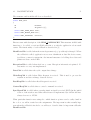
Now another part of initialization structure, SDAI DEVICE DATA will be described.
struct SDAI_DEVICE_DATA
{
U32
SerialNumber;
U32
VendorID;
U32
Type;
U32
ProductCode;
U32
Flags;
37
4.1. PROFINET STACK
union
{
struct SDAI_PN_DEVICE_DATA Pn;
struct SDAI_EIP_DEVICE_DATA Eip;
struct SDAI_PBDP_DEVICE_DATA PbDp;
struct SDAI_ECAT_DEVICE_DATA Ecat;
struct SDAI_MB_DEVICE_DATA Mb;
struct SDAI_EPL_DEVICE_DATA Epl;
} UseAs;
char
ProductName [SDAI_PRODUCTNAME_MAX_LEN]; /**< The product name of the
device */
char
OrderId [SDAI_ORDERID_MAX_LEN];
/**< The order ID of the device
*/
};
Important parts of the structure will be described. For those usually the data from the
skeleton provided with the code are used and their name is pretty self descripted, we will
focus on those that need more explanation. It is important to note, that lot of those data
must match the data filled in GSDML file, whose creation will be covered in 4.4.2 and
theoretical overview is provided in 3.1.3.
Flags - Flags allows to adjust some features of the stack.
UseAs - This illustrates that the SDAI API is designed to be used with many communication protocols. We use Pn for our PROFInet application.
Flags
Flags allow the programmer to specify or adjust some features of the stack to be used in
the application. For the PROFInet protocol the only important flag is SDAI DYNAMIC IO CONFIG
Enabling this flag allow the device to plug/unplug modules and change IO data layout by
the controller during runtime [3]. The change is triggered by ControlReqCbk() with the
control code SDAI CONTROL CODE CFG DATA INFO received from the controller.
After receiving the the request, the application is responsible to plug in or pull out the
modules
to
match
SDAI PN DEVICE DATA
the
configuration
of
the
controller.
38
CHAPTER 4. IMPLEMENTATION
This structure holds PROFInet specific initialization data. Those are mainly network
configuration data for ethernet interface.
struct SDAI_PN_IDENT_DATA
{
U8
Address [4];
U8
Netmask [4];
U8
Gateway [4];
U8
MacAddressDevice [6];
U8
MacAddressPort1 [6];
U8
MacAddressPort2 [6];
U8
StorePermanent;
U8
Alignment;
};
Although the device name and ip address are configured in controller project and stored to
the device from the network, it is important to initialize the device so that it can communicate with the controller, in case they are not connected directly and there is some ethernet switch between. In that case we must choose the ip address, netmask and gateway
in the same subnet so the devices can communicate before new configuration is applied.
SDAI IDENT DATA
Stores
currently
used
device
and
interface
name.
BackEnd
Is
set
to
SDAI BACKEND PN
to
indicate
use
of
PROFInet.
All the fields for initialization are now filled in so that sdai init can be called. After that
we
can
start
with
plugging
of
IO
modules.
Module
plugging
After the initialization structure is filled, we can start to plug in modules to configure IO
data layout for cyclic and acyclic data exchange with controller. It’s position in the initialization process is shown in 4.7. Basically we first define modules to use according to SDAI
rules, then plug them using SDAI API and in the end call SDAI function to notify the
stack
that
plugging
of
the
modules
is
done.
Plugging of modules by the SDAI implements the modular device design feature of
39
4.1. PROFINET STACK
PROFInet IO. It can be imagined as a physically plugging the IO units into the rack
4.8.
Figure 4.8: SDAI units plugging
There are some rules and more consideration to take into account while plugging the
units
and
those
will
be
discused
First let us desribe the SDAI function for plugging the units.
U8 sdai_plug_unit (U8 UnitType, U8 InputSize, U8 OutputSize, U32* pId,
const struct SDAI_CFG_DATA* pCfgData)
UnitType defines whether the module is INPUT, OUTPUT, INPUTOUTPUT or HEAD
module
InputSize is the size of input data of the module in bytes
OutputSize is the size of output data of the module in bytes
pId is 4-byte id of the module. SDAI composes id that 2 first bytes are the subslot of
the module and next 2 bytes are slot number of the module
pCfgData contains moduleIdentNumber and submoduleIdentNumber and this number
must match the number defined in GSDML for the module
40
CHAPTER 4. IMPLEMENTATION
AFter the modules are plugged in, appropriate memory space is created to store the
IO data for modules. The created memory space and access to it is illustrated on 4.9.
Figure 4.9: IO application memory
When the modules are succesfully initialized, we can see 4.10 on the output console.
Figure 4.10: Plugging of IO modules
4.1.2.3
SDAI Data Exchange
After all the modules are succesfully plugged in, we call plugging for a special type of
module, by which we are telling the stack that we are done plugging modules
sdai_plug_unit (SDAI_UNIT_TYPE_PLUGGING_COMPLETE ,0, 0, &DummyId, NULL);
41
4.1. PROFINET STACK
Figure 4.11: SDAI data exchange
Now the device is ready to exchange cyclic and acyclic data, alarms and PROFInet
data through the network. There are 4 important functions from SDAI API that provide
access to the IO data exchange:
U8 sdai_get_data (U32 Id, U8* pStatus, U8* pData)
U8 sdai_set_data (U32 Id, U8 Status, const U8* pData)
WriteReqCbk
ReadReqCbk
While the first two are called by the application, the other two being pointers to funtions
called by stack when respective event occurs. The functions are assigned to pointers during
SDAI
initialization
4.1.2.2.
In the demo application when controller changes the value of the output (which represents
setpoint for the motor speed), callback function DataCbk signals the application that the
output data value has changed. The application reacts by reading respective data from the
sdai data space (by calling sdai get data) and stores them as a setpoint for the PXMC motor
position
(in
the
testing
application).
On the other hand when the value of the input data changes, in our case the quadrature
encoder position, the testing application calls sdai set data to write the input data to the
stack data space,
from where it is cyclicaly transfered to the controller.
Write request and read request are callbacks for acyclic data exchange, it allows the
controller to read and write various parameters stored in the device. Those parameteres
are application specific and are standardized for devices compliant with PROFIdrive
profile specification.
42
CHAPTER 4. IMPLEMENTATION
4.1.2.4
Main Application
Main application is initialized and started in demo platform.c, where main() function is
located. The main loop implementation itself is the in the demo.c file. As the base for the
application was used the application provided with SDAI stack [20], as it provides a lot
of useful structures and sdai function wrappers which can be easily tailored to the applications
needs.
In the demo platform.c the LCD access is initialized, the fieldbus processor is restarted
and two periodic timers are started to trigger NIOS II interrupts. One of them is periodical interrupt timer, this is used for application to detect some external events (buttons
pressed and so on). The second one is timer for PXMC motion control. Since both doesn’t
require less then 1ms interval, they can be started using Altera HAL API, without the
need to trigger the interrupts by harware interrupt generator. 1ms is one tick of the Altera
HAL clock. For periodic application interrupt we choose 10ms and for PXMC 1ms. If the
motion control needed lower step size, it would require us employ interrupt generator in
the
hardware.
Internal
Communication
Internal communication is preserved from the demo application delivered with [20]. That
is the events like callbacks are detected in the demo.c and stored as a particular event
into shared variable between demo.c and demo platform.c. In the main loop the shared
variable is examined for various events and appropriate actions are taken. Events that
can occur are:
EVENT OUTPUT DATA CHANGED is set in callback function for output data
change.
EVENT IDENT DATA CHANGED is set in callback function for identification
data change.
EVENT WRITE IND RECEIVED is set when write request from controller is received.
EVENT READ IND RECEIVED is set when read request from controller is received.
EVENT CONTROL IND RECEIVED is set when control request is received from
controller.
43
4.2. PXMC
EVENT CYCLIC TIMER is triggered every 10ms to allow processing of other than
stack information.
Motor
control
from
board
Mainly for the testing purposes there was created interface to control and observe the motor from the Altera board. This required some changes in both hardware and software design.
All 3 PWM outputs can be enabled or disabled using the switch buttons on the altera board. The LCD printout can switch between the stack information (ip address,
connection status) and the motor information (encoder value, PXMC status). The buttons can be used to increase/decrease speed of the motor or to move the motor position.
Speed of the motor (values fed into PXMC functions) is shown on 7-segment display.
4.2
PXMC
PXMC was used as a library for motion control. It’s succesful deployment to various hardware platforms is described in [12][13][16]. Now we needed to port the library onto NIOS II
processor.
Overview of the PXMC functionality is provided on the figure 4.12.
IRC
C core
DC motor
Figure 4.12: PXMC schema
pxmc do inp is a pointer to a function that is responsible for update of pxmc ap-pxmc
actual positon and pxmc as-pxmc actual speed values.
pxmc do gen is a trajectory generator. We don’t use it in our application.
pxmc do con is a pointer to a position controller which computes pxmc ene.
44
CHAPTER 4. IMPLEMENTATION
pxmc do out is an output generator that translates pxmc ene into PWM signal.
In general scenario there is a feedback loop, where inputs are the date from IRCIncrementary Rotary Encoder and motor and output is the PWM-Pulse Width Modulated signal to control the motor. The other parts of the schema are PXMC specific objects
Discrete control should be run with step intervals around 1ms or less. The execution
of PXMC control loop is then handled by pxmc sfr isr which must be regist as an interrupt handler for an interrupt timer. This is started after pxmc initialization and
it handles the execution of pxmc do inp, pxmc do out and other necessary functions.
It is important to note, that during running of pxmc sfr isr the process shouldn’t be interrupted since it can influence the functionality greatly. This can be achieved either by
defining atomic operation on a processor level or by disabling interrupts during PXMC
execution. This will be described in 4.2.2.
4.2.1
Hardware design
In this section we will describe how the hardware had to be adjusted in order for the device
to be used with a motor. For the motion control application we had a motor adaptation
circuit made. This circuit was created during the application development, therefore we
could discuss the solution with circuit designers during development on Altera board.
After considering the interface available on the board, we decided to use 40-pin GPIO
connector on the board. Assigned signals to GPIO ports as described in [14] are shown
in the following table:
The pinout on the circuit between the board and the motor was designed in a way
that it allow connecting 2 motors to 1 Altera board. It would be done by connecting
another adaptation circuit into series to the first one and each adaptation board would
have 1 motor connected. On the side of altera board, only minor change would be needed
by adding the second set of the signals to the FPGA design and wire them to appropriate
pins. Circuit wiring to allow connect adaptation boards into series is shown on the 4.13
45
4.2. PXMC
Pin Name
Purpose
Direction
GPIO2
axis0 pwm0
Output
GPIO6
axis0 pwm1
Output
GPIO6
axis0 pwm2
Output
GPIO0
axis0 pwm0En
Output
GPIO4
axis0 pwm1En
Output
GPIO8
axis0 pwm2En
Output
GPIO12
axis0 pwm0St
Input
GPIO14
axis0 pwm1St
Input
GPIO16
axis0 pwm2St
Input
GPIO30
axis0 hal0
Input
GPIO32
axis0 hal1
Input
GPIO34
axis0 hal2
Input
GPIO24
axis0 irc cnt chA
Input
GPIO26
axis0 irc cnt chB
Input
GPIO28
axis0 irc index
Input
Table 4.1: Pin assignment for PXMC motion control
Figure 4.13: Wire crossing to connect boards into series
46
4.2.2
CHAPTER 4. IMPLEMENTATION
Software design
As for the software design for PXMC integration, the following steps were necessary. First
to chose the functions from PXMC we need to use and get the source files for them. After
that create pxmc nios ink.c where the board specific PXMC top level calls are implemented. That is mainly to use address space that was created after compilation of hardware
from
4.1.1.
As a base was used the source code from the LX ROCON project developed by PiKRON
for motion control. We used hardware independent PXMC files for initialization, input
reading, output generation and HAL sensor align to the motor position. In the hardware
specific file we put the addresses to read the inputs from the quadrature decode hardware
block
and
write
outputs
to
the
PWM
generator
block.
It was necessary to ensure that during every call to the PXMC routine, all reads and
writes will be atomic processor calls. Since the NIOS II processor doesn’t support atomic
operations [8], we ensured atomicity by disabling all interupts before PXMC routine
started and allowing them again after routine ended. For this we used Altera HAL API
function
InterruptContext = alt_irq_disable_all ();
alt_irq_enable_all (InterruptContext);
4.3
PROFIdrive
PROFIdrive profile specification defines set of rules, modules and objects that take part
in a motion control via PROFInet network.
Those are implemented on top of the
stack, using it’s functions and therefore don’t require intervention to networking stack.
Specification of the PROFIdrive is in [11] and as a code base was used the PROFIdrive
community project from Hilscher [22]. Main ares into which the PROFIdrive can be
decomposed are
Base model Describes the devices in a PROFIdrive application
Cyclic data exchange
Acyclic data exchange
47
4.3. PROFIDRIVE
Mapping of the both communication types from PROFInet to PROFIdrive model is
shown on 4.15.
PN Controller
IO Data
Control
Indication
Alarms
IO Data
Space
Input
Parameter
Access
Output
Response
Setpoin
Application
Peri
Parameter
Manager
ntrol
Peri
Figure 4.14: PROFIdrive mapping to profinet IO
Base model distingueshes between 3 types of devices: Controller, P-Device, Supervisor.
Controller is a host for the overall automation. It is controlling device connected to 1
or more axis.
PDevice is a field peripheral device.
Supervisor is engineering device for supervision.
The P-Device, which is most important for us is composed from 1 or more Drive Units,
each composed of 1 or more Drive Objects. Each object is using PROFInet networking
48
CHAPTER 4. IMPLEMENTATION
services independently of other DOs.
PN Controller
IO Data
Control
Indication
Alarms
IO Data
Space
Input
Parameter
Access
Output
Response
Setpoin
Application
Peri
Parameter
Manager
ntrol
Peri
Figure 4.15: PROFIdrive mapping to profinet IO
Applications are sorted into Application Classes according to needed functionality
and complexity. PROFIdrive classes are:
AP1 - Standard drive
AP2 - Standard drive with distributed controller technology
AP3 - Single axis positioning drive with local motion control
AP4 - Motion control with central interpoaltion and speed setpoint interface
For the simple application in our setup, we might use AP1 or AP3. For using central
interpolation, provided by some PROFIdrive controllers, we would need to use AP4 and
49
4.3. PROFIDRIVE
PROFInet IRT mode since the interpolation on multiple axis requires tight synchronization
of
the
drives.
For the time synchronization will be used the network clock as a base. PROFInet IRT
specification and Precision Time Control Protocol(PTCP) used to sychronize the device
clocks with master clock ensure tight synchronization of the devices. PTCP takes care
of synchronizing the clock in the mean of jitter and deviation, that those cannot rise too
high. PROFInet IRT phases computation that ensures that IRT Red phase ends and
starts at exaclty the same time. On the 4.16 we can se how this is used in order to
synchronize the axis in multiaxis application with tight synchronization demands.
Send Clock
TimeToInput
TimeToOutput
Red Phase
Red Phase
Application
D
PD Param
Manager
P C
D f
P
D
RedPhaseEndDetection
ReadOutputReq
ReadOutputRsp
NewSetpoints
O GOt
ReadInput
D
ues
Proces s
Figure 4.16: PROFIdrive cyclic communication
After the red phase ends, it is certain that all the devices has aquired new data. After
some delay called Time To Output all the devices should apply the values to the axis.
Time To Output is the time that takes the slowest device to write it’s outputs and each
device should modify the value according to it’s own Time To Output. At least Time To
Input time before the next Red phase starts, all the devices should write their inputs to the
stack for transmission in order to ensure the data will be delivered in the next network cycle.
In our application the detection of the Red phase start could by done by wiring the
50
CHAPTER 4. IMPLEMENTATION
signals from the FPGA to the application respectively creating a callback functions for
the signal. The signal switch signal 31 25us base clk is reset according to the Send cycle
of the network and can be use for the purpose, but we didn’t implement the functionality
in the current state of the application.
Profile describes some standard data sets that are being exchanged between devices
for particular appliation purposes. Those data sets are called Standard Telegrams.
4.3.1
Module specifications
The profile defines some values for the PROFInet modules that must be used. For example
every module used as PROFIdrive module must provide parameter access to the controller
and this must be done via Parameter Access Point (PAP) being as submodule 0 of each
module (This made impossible to use the first version of SDAI stack we had, as there only
subslot 0 could be used. There we would have only all PAP modules, or vialoate this rule).
Then
the
IO
specific
submodules
are
plugged.
Profile defines as well the API=14848 to be used with the devices and defines the module
and submodule identification numbers. In our application we used Standard Telegram 6
as it defines IO for single axis 1 setpoint write and read. The module that we created is
therefore composed of:
submodule0 : PAP with submodule number being 0x0000FFFF as defined by specification.
submodule1 : Telegram 6 module with 28 bits input and 20 bits output and submodule
number 0x10000006 as defined by the specification for telegram 6 submodule.
We can see succesfull plugging of the IO module for Parameter access and Standard
telegram 6 on the 4.17.
51
4.3. PROFIDRIVE
Figure 4.17: Debug output telegram 6 modules
4.3.2
Parameter model
A parameter represents an information memory that stores parameter value, parameter
description and text as described in [11].
value contains simplified data representation of a value.
description contains information such as identifier, number of array elements, standardization factor.
text additional text.
Mapping of parameter read and parameter write to the PROFInet stack is described on
4.18 and 4.19. As a base for PROFIdrive source code was used [22].
52
CHAPTER 4. IMPLEMENTATION
)*+,-./0v1
PD Param Manager
PD Para uest
!"# $"#$%&a'(
23ae3 arameter(p#'t4
3ae3Parameter(p#'t4
p#'t
23ae3 aram#'u5#6p#'t4
3ae3Parameter(p#'t4
p#'t
Figure 4.18: PROFIdrive read parameter request
First the application receives the callback from the stack, signalizing parameter read
or parameter write request. The data are taken from the stack memory space and passed
to the PROFIdrive Parameter Manager who then passes it to the PROFIdrive Object Dictionary. Dictionary serves as a memory space for the data while the parameter manager
provides services to access the data.
53
4.4. TESTING
JKLMNQRSTU
PD Param Manager
PD Par78 9:;uest
<= >?@:AB =CABCEF7HI
<VWXHCB:W<7HameterYZBH[\
>=WXHCB:W< arameter(pBH[\
9:B]HF^alue
9:B]HF^alue
<VW9:7_W<aram:B:H9:;]:`BYZBH[\
>=W9:7_W Parameter(ZBH[\
ZBH[
Figure 4.19: PROFIdrive write parameter request
4.4
Testing
At the first stages of development, we tried to test the functionality as isolated as possible. That is to isolate the PXMC, SDAI and PROFIdrive. When we verified the
individual application parts we could move to test the whole PROFIdrive application
with PROFIdrive profile tester.
4.4.1
PLC
For the testing of connection between the device and the controller, we created simple
PROFInet IO network project in Step7 and modified/monitor the remote IO modules.
Simple network with our device and Simatic CPU 315 is on the figure 4.20.
54
CHAPTER 4. IMPLEMENTATION
Figure 4.20: Step7 network configuration
We used this setup with 16bit input and 16bit output modules plugged in to see
wheter the values get updated on the device side and on the controller side respectively.
When this proved to be working, we considered the stack working.
4.4.2
PROFIdrive Profile Tester
For the more complex testing we intended to use PROFIdrive profile tester with CP1616
PCI ethernet card from Siemens. The card can be used as a controller device in a
PROFInet IO network. After connecting the device to the card and running the profile
tester we were unable to establish connection though. Therefore we connected the packet
sniffer
in
between
to
observe
the
communication
with
First let’s see how succesful connection establishment looks in 4.21
the
Wireshark.
4.4. TESTING
55
Figure 4.21: Application Relation establishment with 8bit input module
The controller sends Connect Request message with expected modules listed in the
message. The device compares that with own internal module configuration and sends the
Connect Response. When the modules match, no ModuleDiffBlock is part of the response.
In our application though, using PROFIdrive API 14848, ModuleDiffBlock is part of
the response and therefore making the connection unable to establish. On the figures
4.22 and 4.23 we can see that the device replies with ModuleDiffBlock saying that
for the required API and respective modules and submodules there are no modules.
This was later recognized as a bug from Softing and was being fixed for the new release.
But the bug made the testing with PROFIdrive profile tester impossible with the current
release.
56
CHAPTER 4. IMPLEMENTATION
Figure 4.22: Expected modules from PLC
Figure 4.23: Expected modules response from board
Chapter 5
Conclusion
We developed a device for the motion control capable of communication in the PROFInet
IO network. The device is based on Altera FPGA board DE2-115. In order to achieve
this, we had ported PXMC library onto the NIOS II hardware platform. Porting PXMC
onto new hardware platform required to create necessary FPGA hardware blocks for motion control which were PWM generator and quadrature decoder. Then the software layer
between PXMC generic functions and board specific functions was implemented. Using
PXMC for local motion control was part of a solution in [12][13][16]. We continued in their
work by implementing the library to new hardware platform and using it for a remote motion
control
via
industrial
ethernet
network.
To implement PROFInet IO functionality, we used the SDAI PROFInet stack for Altera
FPGA. We did the enhancements to the hardware design to allow motion control and to
connect the motor. Than we connected the stack software functions with the motion control library in the demo application to test the basic functionality. We implemented part
of the PROFIdrive profile specification, namely Parameter Manager on top of the stack.
As a basis we used PROFIdrive community source code from Hilscher, did modifications
in order to use it in a new hardware platform and integrated it into our design. For the
basic motion control with PROFIdrive controller we created new IO module based on
PROFIdrive standard Telegram 6 for simple 1 axis motor. As a necessary part of that we
developed a GSDML description of the module for integration with standard PROFInet
IO
tools.
During the development we encountered few bugs in the PROFInet stack like unavailability to use arbitrary slots and subslots for the modules or the unavailability to use
PROFIdrive
API
(Application
Process
Identifier)
for
the
data
exchange.
This together with waiting for the bug fixes and consecutive implementing of the func57
58
CHAPTER 5. CONCLUSION
tionality for the new PROFInet stack version greatly slowed the development. We were
not able to test any of the PROFIdrive functionality because this unavailability was in a
oposition with PROFIdrive profile specification requirements. There were as well troubles with the firmware and driver version of the CP1616 card and the version of the
PROFIdrive profile tester. This incompatibility between versions we managed to overcome but the results of the testing couldn’t be taken as a prove of function/disfunction.
Therefore in the end we mapped the way how to use the respective PROFIdrive functions
in our application in order to finish the PROFIdrive compliant IRT application but were
not able to test it ourselves. Except for module specification for standard telegram 6 we
weren’t able to implement any of the cyclic data exchange specification from PROFIdrive
such as application or controller state machine. The main benefit of the work is in the
combining the motion control with PROFInet IRT stack and mapping the PROFIdrive
profile to this particular PROFInet device with partial development of the PROFIdrive
functionality. Since such a projects for PROFIdrive and industrial ethernet motion control in general are usually proprietary solutions with fixed functionality, this can serve as
a starting platform for custom PROFIdrive/PROFInet IRT motion control applications.
,
Bibliography
[1] John A. Kay; Rob A. Entzminger; David C. Mazur:
INDUSTRIAL
ETHERNET- OVERVIEW AND BEST PRACTICES, IEEE (2014)
[2] Hui Li; Hao Zhang; Daogang Peng; Tianyu Chen : Research and Implementation of Embedded Remote Measurement and Control System Based on Industrial
Ethernet, Springer-Verlag Berlin Heidelberg (2012)
[3] SOFTING Industrial Automation GmbH: Simple Device Application Interface
(SDAI) Documentation, SOFTING Industrial Automation GmbH (2014)
[4] PROFINET IRT: Getting Started with the Siemens CPU 315 PLC, Altera
[5] PROFINET Reference design bootstrap and flash access, Altera
[6] Adding new design components to the PROFINET IP , Altera
[7] NIOS II Software Developer’s Handbook , Altera
[8] NIOS II Classic Processor Reference Guide, Altera
[9] GSDML Technical Specificaiton for Profinet IO , PROFIBUS Nutzerorganisation e.V.
(2014)
[10] Michal Sojka; Pavel Pisa: Ocera Make System Manual , 2011
[11] Profile Drive Technology PROFIdrive Technical Specification for PROFIBUS and
PROFINET, PROFIBUS Nutzerorganisation e.V. (2006)
[12] Bc. Martin Meloun: Master’s Thesis: FPGA Based Robotic Motion Control
System , CTU FEE (2014)
[13] Vladimir Burian: Bakalarska prace: Vyuziti programovatelneho pole pro rizenĂ
bezkartacovych motoru , CTU FEE (2011)
59
60
BIBLIOGRAPHY
[14] DE2-115 User Manual , Altera
[15] Somsubhra Ghosh;
Ranjit Kumar Barai; Samar Bhattarcharya;
Prarthana Bhattacharyya; Shubhobrata Rudra; Arka Dutta; Rownick Pyne :An FPGA Based Implementation of a Flexible Digital PID Controller For
a Motion Control System , ICCCI (2013)
[16] Konrad R. Skup Diploma Thesis: Motion Control for Mobile Robots, CTU FEE
(2007)
[17] Siemens Simatic PROFINET system description, Siemens (2008)
[18] PI Working Group PG6 PROFINET IO: PROFINET IRT Engineering,
Guideline for PROFINET, PROFIBUS Nutzerorganisation e.V. (2014)
[19] User Manual: Softing Protocol IP for Profinet v1.20, Softing Industrial Automation
GmbH (2014)
[20] SDAI source code, Softing Industrial Automation GmbH (2014)
[21] PXMC source code, Pavel Pisa, PiKRON Ltd. (2005)
[22] PROFIdrive profile source code, Hilscher Gesellschaft fur Systemautomation GmbH.
(2010)
[23] Manfred Popp:Industrielle komunikation mit profinet, PROFIBUS Nutzerorganisation e.V.
[24] Pavel Pisa; Isabelle Rieucros; Michal Sojka; Konrad Skup :PXMC Documentation
APPENDIX A
Contents of the CD
To the thesis is enclosed the CD with the following items.
• DP.pdf - Diploma thesis in PDF format.
• project.zip - Compressed project source files.
I