1
OC3port Plus
®
Handheld OC3 / ATM Network Analyzer
Users Manual
PN 686284
June 1996, Rev 1, 5/99
© 1996, 1999 Fluke Corporation, All rights reserved. Printed in USA.
All product names are trademarks of their respective companies
Limited Warranty & Limitation of Liability
Each Fluke product is warranted to be free from defects in material and workmanship under normal use and
service. The warranty period is one year and begins on the date of shipment. Parts, product repairs and services
are warranted for 90 days. This warranty extends only to the original buyer or end-user customer of a Fluke
authorized reseller, and does not apply to fuses, disposable batteries or to any product which, in Fluke’s opinion,
has been misused, altered, neglected or damaged by accident or abnormal conditions of operation or handling.
Fluke warrants that software will operate substantially in accordance with its functional specifications for 90 days
and that it has been properly recorded on non-defective media. Fluke does not warrant that software will be error
free or operate without interruption.
Fluke authorized resellers shall extend this warranty on new and unused products to end-user customers only but
have no authority to extend a greater or different warranty on behalf of Fluke. Warranty support is available if
product is purchased through a Fluke authorized sales outlet or Buyer has paid the applicable international price.
Fluke reserves the right to invoice Buyer for importation costs of repair/replacement parts when product
purchased in one country is submitted for repair in another country.
Fluke’s warranty obligation is limited, at Fluke’s option, to refund of the purchase price, free of charge repair, or
replacement of a defective product which is returned to a Fluke authorized service center within the warranty
period.
To obtain warranty service, contact your nearest Fluke authorized service center or send the product, with a
description of the difficulty, postage and insurance prepaid (FOB Destination), to the nearest Fluke authorized
service center. Fluke assumes no risk for damage in transit. Following warranty repair, the product will be
returned to Buyer, transportation prepaid (FOB Destination). If Fluke determines that the failure was caused by
misuse, alteration, accident or abnormal condition of operation or handling, Fluke will provide an estimate of
repair costs and obtain authorization before commencing the work. Following repair, the product will be returned
to the Buyer transportation prepaid and the Buyer will be billed for the repair and return transportation charges
(FOB Shipping Point).
THIS WARRANTY IS BUYER’S SOLE AND EXCLUSIVE REMEDY AND IS IN LIEU OF ALL OTHER
WARRANTIES, EXPRESS OR IMPLIED, INCLUDING BUT NOT LIMITED TO ANY IMPLIED WARRANTY OF
MERCHANTABILITY OR FITNESS FOR A PARTICULAR PURPOSE. FLUKE SHALL NOT BE LIABLE FOR
ANY SPECIAL, INDIRECT, INCIDENTAL OR CONSEQUENTIAL DAMAGES OR LOSSES, INCLUDING LOSS
OF DATA, WHETHER ARISING FROM BREACH OF WARRANTY OR BASED ON CONTRACT, TORT,
RELIANCE OR ANY OTHER THEORY.
Since some countries or states do not allow limitation of the term of an implied warranty, or exclusion or limitation
of incidental or consequential damages, the limitations and exclusions of this warranty may not apply to every
buyer. If any provision of this Warranty is held invalid or unenforceable by a court of competent jurisdiction, such
holding will not affect the validity or enforceability of any other provision.
To locate an authorized service center, visit us on the World Wide Web at:
www.fluke.com
Or call Fluke using the phone numbers listed below:
USA and Canada: 1-888-99-FLUKE (1-888-993-5853)
Europe: +31 402-678-200
Japan: +81-3-3434-0181
Singapore: +65-738-5655
Anywhere in the world: +1-425-356-5500
Fluke Corporation
P.O. Box 9090
Everett, WA 98206-9090
U.S.A.
Fluke Europe B.V.
P.O. Box 1186
5602 BD Eindhoven
The Netherlands
Table of Contents
Chapter
Title
Page
1
Introduction ........................................................................................
Introduction ....................................................................................................
About This Manual .........................................................................................
Who This Manual Is For ..........................................................................
What You Should Know ..........................................................................
How to Use This Manual .........................................................................
Notations and Typographical Conventions ..............................................
OC3port Plus Features and Capabilities .........................................................
The OC3port Plus Handheld Tester: at a Glance .....................................
Specifications ...........................................................................................
Notices, Warnings, Operating Restrictions.....................................................
Laser Operation ..............................................................................................
Checking Your Package .................................................................................
Technical Support...........................................................................................
Service Center Repair .....................................................................................
1-1
1-3
1-3
1-3
1-3
1-3
1-4
1-4
1-6
1-7
1-10
1-11
1-11
1-11
1-12
2
Getting Started ...................................................................................
Introduction ....................................................................................................
OC3port Plus Controls and Connections ........................................................
The Connector Panel ................................................................................
The Front Panel ........................................................................................
The LCD ..............................................................................................
Direct Access Keys ..............................................................................
Status Section.......................................................................................
System Control Keys ...........................................................................
Getting Acquainted with the OC3port Plus Menus.........................................
Accessing a Menu ....................................................................................
Using the Directional Arrow Keys...........................................................
Scrolling through Menu Options..........................................................
Changing the Setting for an Option .....................................................
2-1
2-3
2-3
2-3
2-4
2-4
2-5
2-7
2-10
2-12
2-13
2-14
2-14
2-15
i
OC3port Plus
Users Manual
3
Editing the Setting for an Option..........................................................
Accessing OC3port Plus Submenus..........................................................
Exiting OC3port Plus Submenus ..............................................................
Connecting the OC3port Plus..........................................................................
Connecting the OC3port Plus to Network Devices...................................
Connecting to Remote Devices.................................................................
Connecting the OC3port Plus to a PC or Laptop..................................
Connecting the OC3port Plus to a Modem...........................................
Connecting to a Printer .............................................................................
Connecting to an External Power Supply .................................................
2-16
2-17
2-18
2-18
2-19
2-19
2-19
2-20
2-20
2-21
Setting Up and Operating the OC3port Plus ...................................
Introduction.....................................................................................................
Programming the Overall Operation of the OC3port Plus ..............................
Changing the Default Scrolling Method ...................................................
Turning on the Warning Buzzer ...............................................................
Setting the System Date and Time............................................................
Setting the Communications Speed ..........................................................
Turning Off the Automatic Diagnostic Tests............................................
Parameter Sets ..........................................................................................
Creating a Parameter Set ......................................................................
Naming a Parameter Set .......................................................................
Switching to a Different Parameter Set ................................................
Editing a Parameter Set ........................................................................
Performing Basic Operations ..........................................................................
Turning on the OC3port Plus....................................................................
Turning on the Laser Transmitter .............................................................
Returning to the Introductory Display ......................................................
Resetting the OC3port Plus ......................................................................
Restoring Factory Default Settings...........................................................
Clearing the Error Counters......................................................................
Responding to Low Battery Warnings......................................................
Obtaining Information about Your OC3port Plus.....................................
Storing and Retrieving Test Results .........................................................
Manually Storing Test Results .............................................................
Automatically Storing Test Results in Memory ...................................
Displaying Stored Test Results ............................................................
Deleting Stored Test Results ................................................................
Deleting a Single Record......................................................................
Deleting All Stored Records in a Test Group.......................................
Printing, Downloading, and Remote Control............................................
Connecting to the Serial Port................................................................
Printing Reports and Configuration Information..................................
Pausing a Print Job ...............................................................................
3-1
3-3
3-3
3-4
3-5
3-5
3-6
3-7
3-8
3-8
3-10
3-11
3-11
3-12
3-12
3-14
3-15
3-15
3-15
3-16
3-16
3-17
3-17
3-18
3-19
3-22
3-24
3-25
3-25
3-26
3-26
3-29
3-30
ii
Contents (continued)
Preventing a Report from Being Printed.............................................. 3-30
Controlling the OC3port Plus Remotely .................................................. 3-30
Running the Automatic Diagnostic Tests ....................................................... 3-31
4
SONET/SDH Configuration and Testing ..........................................
Introduction ....................................................................................................
Configuring the Framing Format ....................................................................
Differences between SONET OC3 STS-3c and SDH STM-1..................
Changing the Framing Format .................................................................
Changing the S-Bit Values (optional) ......................................................
Setting Up for Testing STS-3c and STM-1 Signals........................................
Generating Automatic Alarms..................................................................
Setting the Transmit Clock Source...........................................................
Scrambling Payloads................................................................................
Changing the Threshold Setting for Counters ..........................................
Enabling/Disabling PATH FERF Support ...............................................
Monitoring Incoming STS-3c or STM-1 Signals ...........................................
Inserting Errors ...............................................................................................
Modifying the Value of the Payload Pointer ..................................................
Generating Alarms..........................................................................................
Transmitting an Alarm .............................................................................
Turning Off an Alarm ..............................................................................
Viewing Alarms Stored in the Alarm Log ...............................................
Removing All Alarms from the Alarm Log .........................................
Responding to an LOS Condition ........................................................
In-Service Signal Monitoring .........................................................................
4-1
4-3
4-3
4-3
4-4
4-5
4-7
4-7
4-9
4-10
4-11
4-12
4-13
4-15
4-17
4-18
4-19
4-20
4-20
4-22
4-23
4-23
5
Configuring for ATM Network Testing .............................................
Introduction ....................................................................................................
Configuring a Receive Filter...........................................................................
Configuring an ATM Cell Transmission Stream ............................................
Some Suggestions for Configuring Multiple Cell Streams ......................
Configuring a VBR / Poisson Transmission Source.................................
Other ATM Configuration Options ................................................................
Payload Scrambling Option .....................................................................
Coset Polynomial Option .........................................................................
Correction Algorithm Option ...................................................................
Background Traffic Option ......................................................................
Header Type Option.................................................................................
Changing the Form for Expressing the PCR and SCR .............................
Large Transmit Queue..............................................................................
5-1
5-3
5-3
5-7
5-17
5-18
5-18
5-19
5-20
5-21
5-22
5-22
5-24
5-25
6
Testing ATM Networks ...................................................................... 6-1
Introduction .................................................................................................... 6-3
iii
OC3port Plus
Users Manual
Starting Stream Transmission .........................................................................
Transmitting OAM Cells on a Single Circuit ...........................................
Transmitting OAM Cells on Multiple Circuits .........................................
Monitoring an ATM Network .........................................................................
Monitoring ATM Traffic with a Receive Filter ........................................
Capturing ATM Cells ...............................................................................
Configuring the OC3port Plus for Capturing ATM Cells ....................
Starting a Cell Capture .........................................................................
Looking at the Captured Cells..............................................................
Displaying the Results of the Previous Cell Capture............................
Capturing ILMI Cells ...............................................................................
Configuring the OC3port Plus for Capturing ILMI Cells.....................
Starting an ILMI Cell Capture..............................................................
Looking at Captured ILMI Cells ..........................................................
Capturing OAM Cells...............................................................................
Configuring the OC3port Plus for Capturing OAM Cells ....................
Starting an OAM Cell Capture .............................................................
Looking at Captured OAM Cells .........................................................
Searching for AAL Traffic on an ATM Network .....................................
Scanning Circuits for ATM Activity...............................................................
Setting Up an ATM Activity Scan............................................................
Scanning an ATM Circuit.........................................................................
Printing the Results of an Activity Scan ...................................................
Displaying the Results of the Previous Activity Scan ..............................
Using the ATM Traffic Templates..................................................................
ATM Traffic Templates: a Description ....................................................
20% SPREAD ......................................................................................
RAMPDOWN ......................................................................................
BER Test ..............................................................................................
POLICE 10MBS ..................................................................................
Selecting and Loading an ATM Traffic Template....................................
Starting Transmission with a Loaded Template .......................................
Editing a Template....................................................................................
Quality of Service Tests ..................................................................................
Cell Loss Test ...........................................................................................
Setting Up a Cell Loss Test ..................................................................
Running a Cell Loss Test .....................................................................
Re-running a Cell Loss Test .................................................................
Remote Cell Loss Test..............................................................................
Setting Up a Remote Cell Loss Test.....................................................
Setting up the Master Unit....................................................................
Setting Up the Slave Unit.....................................................................
Running a Remote Cell Loss Test ........................................................
Understanding Cell Loss Test Results..................................................
Exiting and Returning to a Test in Progress .........................................
iv
6-4
6-5
6-7
6-9
6-9
6-14
6-15
6-19
6-20
6-22
6-22
6-23
6-27
6-27
6-28
6-28
6-29
6-30
6-31
6-34
6-34
6-38
6-40
6-42
6-42
6-42
6-43
6-43
6-43
6-43
6-43
6-45
6-46
6-46
6-47
6-47
6-50
6-51
6-51
6-52
6-53
6-59
6-64
6-65
6-65
Contents (continued)
Cell Delay Variation Tests .......................................................................
1-point CDV Test.................................................................................
Setting Up a 1-point CDV Test............................................................
Running a 1-point CDV Test ...............................................................
2-point CDV Test.................................................................................
Setting Up a 2-point CDV Test............................................................
Running a 2-point CDV Test ...............................................................
Cell Transfer Delay Test ..........................................................................
Setting Up a Cell Transfer Delay Test .................................................
Running a Cell Transfer Delay Test ....................................................
Understanding Cell Transfer Delay Test Results .................................
Exiting a Cell Transfer Delay in Progress Test....................................
Bit Error Rate Test (BERT) ............................................................................
Setting up a BERT Test .......................................................................
Creating Your Own BERT Test Pattern...............................................
Running an ATM BERT Test ..............................................................
Injecting Individual BERT Errors........................................................
IP Ping Test ....................................................................................................
Setting Up the OC3port Plus to Send an IP Message...............................
Sending an IP Message ............................................................................
Receiving an IP Message .........................................................................
6-66
6-66
6-66
6-68
6-70
6-70
6-71
6-72
6-73
6-74
6-75
6-75
6-76
6-76
6-78
6-79
6-80
6-81
6-81
6-85
6-87
Appendices
A Applications ............................................................................................. A-1
B OC3port Plus ATM Transmission............................................................ B-1
C Glossary ................................................................................................... C-1
Index
v
OC3port Plus
Users Manual
vi
List of Tables
Table
2-1.
2-2.
2-3.
2-4.
3-1.
3-2.
3-3.
3-4.
3-5.
4-1.
4-2.
4-3.
4-4.
5-1.
5-2.
5-3.
6-1.
6-2.
6-3.
Title
OC3port Plus Direct Access Keys and their Function ....................................
OC3port Plus General Status LEDs................................................................
SONET Alarms Detected by the OC3port Plus on the Status LEDs ..............
Description of the System Control Keys on the OC3port Plus .......................
Storage Limits for Test Records .....................................................................
RJ-11 Pin Descriptions ...................................................................................
Serial Port 25-pin Computer Connection Pin Descriptions ............................
Serial Port 25-Pin Modem/Printer Connection Pin Descriptions....................
OC3port Plus Diagnostic Test Results for ATM and SONET........................
STS-3c/STM-1 Alarms...................................................................................
STS-3c/STM-1 Measurement Results ............................................................
Description of STS-3c/STM-1 Errors.............................................................
Alarms Transmitted by the OC3port Plus.......................................................
Receive Filter Setup Parameters .....................................................................
OC3port Plus Transmission Stream Parameters .............................................
Valid Combinations of Traffic Parameter and Traffic Source Selections.......
Captured Buffer Size ......................................................................................
BERT Test Patterns ........................................................................................
BERT Error Injection Rates............................................................................
vii
Page
2-6
2-8
2-9
2-11
3-18
3-27
3-27
3-27
3-32
4-8
4-15
4-16
4-20
5-6
5-15
5-17
6-15
6-78
6-78
OC3port Plus
Users Manual
viii
List of Figures
Figure
1-1.
2-1.
2-2.
2-3.
2-4.
2-5.
3-1.
4-1.
5-1.
6-1.
6-2.
Title
OC3port Plus at a Glance ...............................................................................
OC3port Plus Connector Panel .......................................................................
OC3port Plus LCD and Direct Access Keys ..................................................
OC3port Plus Status LEDs .............................................................................
The System Keys Control the Entire Unit. .....................................................
OC3port Plus Menu System (Version 3.3) .....................................................
OC3port Plus ON/OFF switch........................................................................
In-service Monitoring of Network Performance.............................................
UNI and NNI Cell Structure Differences........................................................
Remote Cell Loss test connections .................................................................
Remote Cell Loss Testing...............................................................................
ix
Page
1-6
2-3
2-5
2-7
2-11
2-14
3-12
4-24
5-23
6-52
6-53
OC3port Plus
Users Manual
x
Chapter 1
Introduction
Contents
Introduction ....................................................................................................
About This Manual .........................................................................................
Who This Manual Is For ..........................................................................
What You Should Know ..........................................................................
How to Use This Manual .........................................................................
Notations and Typographical Conventions ..............................................
OC3port Plus Features and Capabilities .........................................................
The OC3port Plus Handheld Tester: at a Glance .....................................
Specifications ...........................................................................................
Notices, Warnings, Operating Restrictions.....................................................
Laser Operation ..............................................................................................
Checking Your Package .................................................................................
Technical Support...........................................................................................
Service Center Repair .....................................................................................
Page
1-3
1-3
1-3
1-3
1-3
1-4
1-4
1-6
1-7
1-10
1-11
1-11
1-11
1-12
1-1
OC3port Plus
Users Manual
1-2
Introduction
Introduction
1
Introduction
The OC3port Plus portable hand-held tester provides an extensive set of OC3
and ATM testing capabilities that address a broad range of test requirements for
OC3- and ATM-based transmission and communications systems. The OC3port
Plus is specifically designed to allow you to test any type of OC3/ATM equipment
for proper operation, configuration, compliance, and interoperability.
This chapter describes the features and capabilities of the OC3port Plus and
provides important information about the operation and use of the tester.
About This Manual
The OC3port Plus Users Manual describes how to operate the OC3port Plus
network analyzer and provides step-by-step instructions on how to perform
network testing and evaluation of ATM networks and equipment.
Who This Manual Is For
This manual provides pertinent technical information and instruction on the
operation and use of the OC3port Plus. It is written for anyone who uses this
product to test and troubleshoot OC3 and ATM network problems, for those
involved in network installation and maintenance, and for individuals who perform
network acceptance testing.
What You Should Know
This manual is not meant to be a SONET or ATM tutorial. A basic familiarity with
wide-area networking, in general, and an in-depth understanding of SONET, OC3
networks and ATM protocols, in particular, are required to effectively understand
and use this manual.
How to Use This Manual
We suggest that the first-time user continue with this chapter, “Introduction”. This
chapter describes the features and capabilities of the OC3port Plus and familiarizes
you with the safety precautions regarding its use.
Next read Chapter 2 “Getting Started”. Before you begin using the OC3port Plus,
you should understand the functions of the keys and status indicators as well as
other elements on the unit’s front panel. You also need to understand the menu
interface and how to navigate through the OC3port Plus menus. This chapter
covers these fundamentals.
After you configure the OC3port Plus, you can go directly to any of the
subsequent chapters that show you how to perform specific tests or operations.
1-3
OC3port Plus
Users Manual
This book also contains a Glossary of terms that are used throughout this manual.
Terms found in the Glossary area highlighted in text when they are first used.
Notations and Typographical Conventions
The following notations and typographical conventions are used in this manual:
Key names
The names of keys are in boldface type.
For example, the AUTOTEST key and the Print key.
Key sequences
A plus sign, as in SHIFT 1 + M, indicates that you should press and hold down
the SHIFT 1 key and then press the M key.
Screen names
The names of screens are in capital letters and boldface type.
For example, the SYSTEM INFORMATION screen.
Options
Options are boldface type. For example, the Date option.
Arrow keys
The arrow keys are the four keys that encircle the ENTER key.
The name of an individual arrow key refers to the direction in which the arrow
points: the Down Arrow key, the Left Arrow key, the Right Arrow key, and
the Up Arrow key.
Italics
Italic type is used for emphasis.
For example: Do not operate the unit in the presence of flammable gases.
Lists
Procedures are shown in sequentially numbered lists.
Monospace
Monospace type is used to indicate messages displayed on the tester’s LCD.
For example, INITIALIZING ANALYZER.
Cautions
A caution message advises you that failure to take or avoid a specific action
can result in loss of data.
All cautions are preceded by the word Caution.
Warnings
A warning message cautions you that failure to take or avoid a specific action
can result in physical harm to you or damage to the tester.
All warnings are preceded by the symbol
and the word Warning.
OC3port Plus Features and Capabilities
The OC3port Plus combines SONET testing features with advanced ATM testing
features, giving you the ability to quickly test and troubleshoot any OC3 circuit as
well as test ATM equipment and services for proper operation and conformance.
At the physical layer, the OC3port Plus can be used to diagnose many common
OC3 network problems. The tester provides complete OC3 Section, Line, and Path
error and alarm transmission and monitoring capabilities that enable you to
1-4
Introduction
OC3port Plus Features and Capabilities
1
effectively monitor and test OC3 networks from any access point. The OC3port
Plus also provides the following:
•
OC3 pointer control and monitoring
•
Support for SONET and SDH framing formats
•
Date and time stamping of OC3 alarm occurrences
•
A passive monitoring mode, which allows for non-intrusive testing
•
Automatic testing of OC3 circuits so that you can obtain immediate pass/fail
results and quickly assess problems with SONET networks.
In addition, the OC3port Plus offers a comprehensive set of advanced ATM testing
capabilities, which includes:
•
Automatic scanning of active virtual circuits
•
Ability to transmit up to eight ATM traffic sources simultaneously
•
Quality of Service tests: Cell Delay, Cell Variation, and Cell Loss
•
Cell payload capture and viewing
•
Various cell transmission modes, including single cell, programmable burst
size, and constant rate
•
Transmission of ATM traffic that simulates CBR, VBR, and UBR service
categories with programmable random, poisson, or constant traffic distribution
patterns
•
AAL type recognition
•
OAM cell transmit and monitoring of AIS, RDI, and loopback F4 and F5
flows
•
Quality of service measurements: CTD (mean, max), CDV (max), CLR, and
CMR.
In addition to advanced diagnostic and testing capabilities, the OC3port Plus gives
you immediate feedback on the condition of any OC3 circuits under test through
its front-panel LEDs. The tester also lets you store and print test results, making it
possible for you to gather and later examine network statistics.
For long-term monitoring, the OC3port Plus can be connected to a network, which
can be monitored remotely through a modem connected to a PC with Fluke’s
remote control software. This gives you the added advantage of being able to leave
the OC3port Plus connected at a customer premise or central office location and
dial into the tester from a PC or laptop computer from a central monitoring
location.
1-5
OC3port Plus
Users Manual
The OC3port Plus Handheld Tester: at a Glance
The OC3port Plus is an easy-to-use handheld tester. It is rugged yet lightweight, so
you can use it anywhere.
RS-232 port provides an interface
for connecting to a printer, remote
control, and downloading test results
For-line by 20-characters
backlit LCD displays test
results and setup
parameters
Six function keys provide
direct access to setup and
configuration options
OC3port
PLUS
Arrow keys navigate through
menu items. Up and Down
keys display options. Left
and Right keys choose
settings
SONET
ATM
BERT
AUTO
ALARMS
OPTIONS
ENTER
START
STOP
EDIT
Front panel LEDs provide
immediate indications of
OC3 Section, Line, and Path
errors and alarms
HISTORY
STATUS
CURRENT
STATUS
START/STOP key to
easily control the running
of tests
SECTION LOS
ATM CELL LOCK
SECTION LOF
ALARMS
SECTION OOF
PATTERN / ERROR INSERT
LOOPBACK
LINE FERF
LINE AIS
PATH FERF
PATH AIS
PATH YELLOW
POWER
PRINT
PATH LOSS OF POINTER
MEMORY
CLEAR
DELETE
ESC
Print stored test results to a
printer or PC
za001f.eps
Figure 1-1. OC3port Plus at a Glance
1-6
Introduction
OC3port Plus Features and Capabilities
1
Specifications
This section describes the physical and operational characteristics of the OC3port
Plus.
OC3 Physical
Bit rate: 155.52
Mbps ± 20 ppm
Receiver:
•
Single-mode version:
Maximum input power: -8 dBm
Minimum receive sensitivity: -28 dBm
•
Multi-mode version:
Maximum input power: -14 dBm
Minimum receive sensitivity: -32.5 dBm
•
UTP-155 version: ATM Forum UTP-155-PMD compliant
Transmit Outputs:
•
Single-mode version:
Average output power: -12.5 dBm (typical)
Range: -15 dBm to -8 dBm
Center wavelength: 1260 to 1360 nm, spectral width: 7.7 nm
•
Multi-mode version:
Average output power range: -19 dBm to -14 dBm
Center wavelength: 1270 to 1380 nm, spectral width: 130 nm
•
UTP-155 version: ATM Forum UTP-155-PMD compliant
NRZ encoded
Transmit level: 0.90 - 1.10 Vpp
1-7
OC3port Plus
Users Manual
Physical
Size:
Approximately 10 in (L) by 6.75 in (W) by 2 in (H)
Weight:
2.50 lbs.
Display:
Back-light, 4-line by 20-character text
Connectors:
Single-mode version: FC/PC or SC Duplex
Multi-mode version: SC Duplex
UTP-155 version: RJ-45
Power
AC operations:
Battery type:
Battery life:
Operates from an external AC adapter/charger.
Operates from internal rechargeable Ni-Cad battery.
Minimum battery life is three hours of continuous use.
Recharge time:
12 hours.
Environmental
Operating temperature:
Storage temperature:
Humidity:
0 °C to 50 °C
-20 °C to +60 °C
5 % to 90 % non-condensing
Serial Communications Port
Port: EIA/RS-232
Connector:
RJ-11 connector
Baud rates:
1200, 2400, 9600
Flow control:
XON/XOFF or RTS/CTS
Standards Compliance
Applicable sections of ATM Forum UNI 3.1
Applicable sections of ANSI T1.105
Applicable sections of BellCore TR-NWT-000253
Applicable sections of ITU I.432, ITU I.610, and ITU I.510
1-8
Introduction
OC3port Plus Features and Capabilities
1
Regulatory Compliance
Instrument complies with ETL product category 31
Instrument complies with FCC Part 15, Subpart B, Class A
OC3 Errors Detected
Section, Line, and Path Bit Interleave Parity errors; Line and Path Far-End-Block
errors.
OC3 Alarms Detected
Signal Loss, Loss of Frame, Line FERF, Line AIS, Path FERF, Path AIS, Path
YELLOW, Loss of Pointer alarms.
OC3 Alarms Generated
Signal Loss, Loss of Frame, Line FERF, Line AIS, Path FERF, Path AIS,
Path YELLOW alarms.
SDH-STM-1 Support
SDH option available which provides control and monitoring of S-bits.
Pointer Features
Positive and negative pointer adjustment, programmable pointer value, viewable
received pointer value: current, minimum, and maximum.
ATM Layer
Cell mapping:
ATM cells carried in the OC3 payload are byte-aligned.
Cell rate adaptation:
Provided by the insertion of idle cells.
Performed using the HEC mechanism as described in ITU I432.
HEC is generated and checked as described in ITU I.432.
Cell delineation:
1-9
OC3port Plus
Users Manual
Notices, Warnings, Operating Restrictions
This product complies with UL 1950 (2/26/93). This compliance has been certified
for both the United States and Canada by ETL Testing Laboratories and will carry
the ETL listing mark. This product meets the requirements of
FCC Part 15-Subpart A, electronics emission and susceptibility.
Service and adjustment of this unit is to be performed only by trained Fluke
service personnel. The following general safety precautions must be observed
during all phases of operation, service and repair of this instrument. Failure to
comply with these precautions or with specific warnings in this book violate safety
standards of design, manufacture, and intended use of this instrument. Fluke
Corporation assumes no liability for the customer’s failure to comply with these
requirements.
•
Potential Danger
Explosion Hazard: Do not operate the system in the presence of flammable
gases.
•
Hazardous Material: Should the LCD display become damaged, the liquid
crystal material can leak. Avoid all contact with this material, especially
swallowing. Use soap and water to thoroughly wash all skin and clothing
contaminated with the liquid crystal material.
•
Electric Shock Hazard: Do not remove the system covers. To avoid electric
shock, use only the supplied power module.
•
Laser: This product contains a Class 1 Laser Device. Do not look into the
connector labeled "output". Invisible laser energy is emitted from that
connector whenever the laser is on.
Warning
AC adapter/charger:
Only the Fluke-supplied AC adapter/charger may be used
with this equipment. The use of any other AC
adapter/charger is expressly forbidden and will void all
warranty rights.
Outlet:
The AC socket outlet shall be installed near the equipment
and shall be easily accessible. Failure to have this outlet
easily accessible may constitute a safety hazard.
1-10
Introduction
Laser Operation
1
Laser Operation
The single-mode version of the OC3port Plus contains a laser transmitting device.
As a safety precaution, this transmitter is off when the tester is powered on. For
the tester to function, you must turn on the laser setting. See "Starting the OC3port
Plus" in Chapter 3 for instructions on how to turn on the laser transmitter. The
laser turns on automatically if there is an input signal while you are running the
automatic diagnostic tests.
Checking Your Package
Take time to check your OC3port Plus package. The following items are included:
• 3'TSVX4PYW2IX[SVO%REP]^IV9WIVW1ERYEP
• %'EHETXIVGLEVKIV
• 3'TSVX4PYWRIX[SVOEREP]^IV
• 6.XS6.GEFPI
• 6.XS(&JIQEPIEHETXIV
• (&XS(&JIQEPIEHETXIV
• DB-9 to DB-25 male adapter
If your package does not contain an item from this list contact Fluke at one of the
telephone numbers listed under "Technical Support" below.
Technical Support
Fluke Corporation offers a variety of support options to help you get the most from
your OC3port Plus. If you require technical support, please have the following
information available:
•
•
•
•
•
•
Your name and company.
OC3port Plus model number and serial number.
OC3port Plus software revision that appears when you power on the unit.
Any error messages or flags that appear on the screen.
Make, model numbers, and configurations of equipment under test.
A printout of the setup parameters for the OC3port Plus.
For application or operation assistance or information about the OC3port Plus,
call:
USA and Canada: 1-888-993-5853
Europe: +31 402-678-200
Japan: +81-3-3434-0181
Singapore: +65-738-5655
Anywhere in the world: +1-425-356-5500
Or, visit Fluke’s web site at www.fluke.com.
1-11
OC3port Plus
Users Manual
Service Center Repair
If the OC3port Plus requires service, pack it in the original shipping container and
send it, postage paid and insured, to the nearest Fluke Service Center. Include a
written description of the problem. Fluke assumes no responsibility for shipping
damage.
If the OC3port Plus is covered under warranty, it will be properly repaired or
replaced (at Fluke’s option) and returned to you, postage paid, at no charge. See
the registration card for warranty terms. If the warranty has lapsed, Fluke will
repair the unit for a fixed fee and return it to you postage paid. Contact the nearest
Service Center for information and repair prices.
For service information in the USA, call 1-888-99-FLUKE (1-888-993-5853).
Outside the USA, contact the nearest Service Center.
Visit Fluke’s web site at www.fluke.com.
1-12
Chapter 2
Getting Started
Contents
Introduction......................................................................................................
OC3port Plus Controls and Connections .........................................................
The Connector Panel .................................................................................
The Front Panel .........................................................................................
The LCD ...............................................................................................
Direct Access Keys...............................................................................
Status Section........................................................................................
System Control Keys ............................................................................
Getting Acquainted with the OC3port Plus Menus .........................................
Accessing a Menu .....................................................................................
Using the Directional Arrow Keys............................................................
Scrolling through Menu Options ..........................................................
Changing the Setting for an Option ......................................................
Editing the Setting for an Option..........................................................
Accessing OC3port Plus Submenus..........................................................
Exiting OC3port Plus Submenus ..............................................................
Connecting the OC3port Plus ..........................................................................
Connecting the OC3port Plus to Network Devices...................................
Connecting to Remote Devices .................................................................
Connecting the OC3port Plus to a PC or Laptop..................................
Connecting the OC3port Plus to a Modem...........................................
Connecting to a Printer..............................................................................
Connecting to an External Power Supply .................................................
Page
2-3
2-3
2-3
2-4
2-4
2-5
2-7
2-10
2-12
2-13
2-14
2-14
2-15
2-16
2-17
2-18
2-18
2-19
2-19
2-19
2-20
2-20
2-21
2-1
OC3port Plus
Users Manual
2-2
Getting Started
Introduction
2
Introduction
Chapter 2 first acquaints you with the physical layout of the OC3port Plus so that
you know where the various controls and connections are located and understand
the functions of the keys and general status indicators. Next, it describes the menu
interface and shows you how to access the menus and navigate through them.
Finally, chapter 2 describes how to connect the OC3port Plus to an external power
source and how to connect the tester to the network and to remote devices.
OC3port Plus Controls and Connections
The OC3port Plus has two main panels: a connector panel and a front panel with
status and control sections. Take a moment to become familiar with these two
panels so that you can work more efficiently.
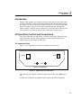
The Connector Panel
Figure 2-1 is a representation of the OC3port Plus connector panel.
5VDC
RS232
IN
OUT
Single mode displayed
za002f.eps
Figure 2-1. OC3port Plus Connector Panel
The connector panel, which is located on the top of the tester, has a 5V DC input
jack.
Use this jack to attach the AC adapter/charger supplied by Fluke Corporation.
2-3
OC3port Plus
Users Manual
Warning
Do not disconnect the AC adapter/charger while the
OC3port Plus is powered on. Doing so can result in the
corruption of current or stored test results.
Only an AC adapter/charger supplied by Fluke can safely
be used with the OC3port Plus. Use of any other adapter
voids your warranty and can damage the tester.
Network connectors. The IN and OUT connector jacks are
attached to the OC3 network. Depending on the type of
interface, you will attach single-mode, multi-mode, or
twisted pair connections to these jacks.
EIA-232 serial port. This is a RJ-11 female jack that
accepts the Fluke-supplied serial conversion cable. Using
this cable, you can download to a PC or a printer and
upload the latest version of OC3port Plus software.
The Front Panel
The front panel contains four main sections:
•
LCD
•
Direct access keys
•
Status section
•
System keys
Descriptions of these sections follow.
The LCD
The LCD is located at the top of the tester. It is a four-line by 20-character backlight display that presents the OC3port Plus menus, test configurations, and results
of specific tests.
2-4
Getting Started
OC3port Plus Controls and Connections
2
Direct Access Keys
The OC3port Plus has six direct access keys that provide immediate access to tests
and user setup options. These keys are located on the upper left side of the unit
directly across from the ENTER key.
Figure 2-2 is a representation of the LCD and the direct access keys.
OC3port
SONET
ATM
BERT
AUTO
ALARMS
OPTIONS
START
STOP
PLUS
ENTER
EDIT
za003f.eps
Figure 2-2. OC3port Plus LCD and Direct Access Keys
2-5
OC3port Plus
Users Manual
The Table 2-1 lists the six direct access keys other front panel keys and describes
their function.
Table 2-1. OC3port Plus Direct Access Keys and their Function
Direct Access Key
Function
SONET
Accesses OC3 and STS-3c setups and tests.
ATM
Accesses ATM setups and tests.
BERT
Accesses Bit Error Rate test parameters and tests.
AUTO
Accesses automatic diagnostic tests and identifies virtual
paths/channels with ATM activity.
ALARMS
Displays, clears, and controls SONET alarms.
OPTIONS
Stores user-defined opt8ions in internal memory.
START/STOP
Starts and stops testing.
In burst mode, pressing this key initiates a burst of ATM cells.
In transmit mode, pressing this key once pauses transmission;
pressing the key again causes transmission to resume.
2-6
EDIT
Places the tester in Edit mode for changing the parameters for an
option.
ENTER
Accepts user options and editing changes.
Getting Started
OC3port Plus Controls and Connections
2
Status Section
The lower middle section of the front panel on the OC3port Plus contains 24 LEDs
that represent the operating and alarm status of the OC3port Plus and any attached
network.
Figure 2-3 is a representation of the status section.
HISTORY
STATUS
CURRENT
STATUS
SECTION LOS
ATM CELL LOCK
SECTION LOF
ALARMS
SECTION OOF
PATTERN / ERROR INSERT
LOOPBACK
LINE FERF
LINE AIS
PATH FERF
PATH AIS
PATH YELLOW
POWER
PATH LOSS OF POINTER
za004f.eps
Figure 2-3. OC3port Plus Status LEDs
The six general status LEDs appear on the left.
These LEDs provide laser transmitter status, ATM status, and power status
information.
2-7
OC3port Plus
Users Manual
Table 2-2 lists the general status LEDs and their meanings.
Table 2-2. OC3port Plus General Status LEDs
LED Name
STATUS
LED Condition
Meaning
Slow blinking
Indicates that the laser transmitter is set to
OFF. (for single-mode units only)
Constant Green
Indicates that the laser transmitter is set to
ON. (For single-mode units only).
ATM CELL LOCK
On
Indicates that ATM cell delineation has been
achieved.
ALARMS
On
Indicates that alarms are being transmitted
PATTERN / ERROR
INSERT
On
Indicates that patterns or errors are being
transmitted.
LOOPBACK
On
Indicates that the unit is in line loopback or in
cell loopback mode.
POWER
ON
Indicates adequate AC or battery power.
Blinking
Indicates that the battery is low on power.
The remaining 18 LEDs, found on the right side of the tester, indicate the status of
the connected SONET network.
The OC3port Plus can detect nine separate alarms.
The red LEDs indicate active or current alarms, while the yellow (History) LEDs
indicate that an alarm occurred at some time in the past but is no longer being
detected.
2-8
Getting Started
OC3port Plus Controls and Connections
2
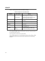
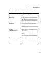
Table 2-3 lists the alarms the OC3port Plus can detect and their meanings.
Table 2-3. SONET Alarms Detected by the OC3port Plus on the Status LEDs
SONET Status LED
Description
SECTION LOS
(Loss of Signal)
Lights when an incoming optical OC3 signal cannot be
detected.
SECTION LOF
(Loss of Frame)
Declared when a Section OOF condition persists for
three milliseconds.
This three-millisecond timer does not reset until an inframe condition also persists for three milliseconds,
prohibiting oscillations and the declaration of an LOF
in the presence of intermittent OOF conditions.
SECTION OOF
(Out of Frame)
Declared when four consecutive STS-3c frames
containing one or more framing pattern errors are
received.
A Section OOF alarm is removed when two sequential
frames with correct framing patterns are detected (an
in-frame condition).
LINE FERF
(Far End Receive Failure)
Detects the presence of a Line FERF in the received
STS-3c stream.
Declared when a “110” pattern is detected in bits 6, 7
and 8 of the K2 framing byte for five consecutive
frames.
A LINE FERF alarm is removed when a pattern other
than “110” is detected for five consecutive frames.
LINE AIS
(Line Alarm Indication Signal)
Detects the presence of a Line FERF in the received
STS-3c stream.
Declared when a “111” pattern is detected in bits 6, 7
and 8 of the K2 framing byte for five consecutive
frames.
A Line AIS alarm is removed when a pattern other
than “111” is detected for five consecutive frames.
2-9
OC3port Plus
Users Manual
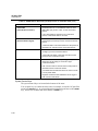
Table 2-3. SONET Alarms Detected by the OC3port Plus on the Status LEDs (cont.)
SONET Status LED
PATH FERF
(Far End Receive Failure)
Description
Dedicated when the 4th bit FEBE field within the Path
Status Byte (G1) is set to “1001” for two consecutive
frames.
If any other pattern is present for two consecutive
frames, a Path FERF alarm is removed.
PATH AIS
(Alarm Indication Signal)
Declared when an all-ones pattern is detected in the
pointer bytes (H1 and H2) for three consecutive STS-3c
frames.
A Path AIS alarm is removed whenever a valid pointer is
detected in H1 and H2 for three consecutive frames.
PATH YELLOW
Declared whenever bit 5 of the Path Status Byte (G1) is
set high (1) for five consecutive frames.
A path YELLOW alarm is removed when bit 5 returns
low (0) for five consecutive frames.
PATH LOSS OF POINTER
Declared whenever a normal pointer (generally values
within the 0 to 782 range) is not found in eight
consecutive frames.
Path Loss of Pointer is removed when a valid pointer is
detected for three consecutive frames.
A received Path AIS indication does not result in a Path
Loss of pointer alarm.
Negative and Positive stuff indications do not trigger a
Path Loss of Pointer alarm.
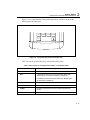
System Control Keys
The system control keys are located at the bottom of the tester.
You use these keys to control the entire unit; for example, to turn the OC3port Plus
on and off (ON/OFF key), to print configuration information and test results (PRINT
key), and to clear counters and delete alarms. (CLEAR key)
2-10
Getting Started
OC3port Plus Controls and Connections
2
Figure 2-4 is a representation of the system control keys, which are found on the
bottom part of the front panel.
PRINT
MEMORY
CLEAR
DELETE
ESC
za005f.eps
Figure 2-4. The System Keys Control the Entire Unit.
Table 2-4 lists the system control keys and describes their usage.
Table 2-4. Description of the System Control Keys on the OC3port Plus
Key Name
Description
ON/OFF
Turns the unit on and off.
ESC
A single press returns you to the introductory display (see
“Returning to the Introductory Display” in Chapter 3).
A double-press resets the OC3port Plus (see “Resetting the
OC3port Plus” in Chapter 3).
PRINT
Prints test results and configuration information.
MEMORY
Stores and retrieves test results.
CLEAR
Resets the test result counters and deletes individual test
results.
DELETE
Clears the alarm history LEDs and deletes stored results.
2-11
OC3port Plus
Users Manual
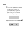
Getting Acquainted with the OC3port Plus Menus
The OC3port Plus is a menu driven system. Each time you power on the unit, a
series of self-tests and automatic ATM and SONET diagnostic tests is performed.
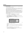
Note
The single-mode version of the OC3port Plus contains a laser
transmitting device. As a safety precaution, this transmitter is off
when the unit is powered on. You must turn the laser on each time
you turn on the unit. It remains on until you shut off the unit.
See "Turning on the Laser Transmitter" in this chapter for
instructions on how to turn on the laser transmitter. Note that the
laser comes on automatically if the OC3port Plus detects an input
signal while you are running the automatic diagnostic tests.
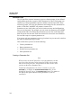
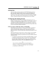
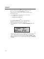
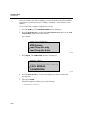
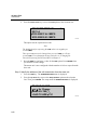
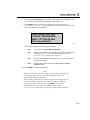
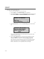
While the automatic tests are running, you see displays similar to this:
******************************
ANALYZING
SIGNAL 14
******************************
za006f.eps
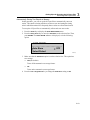
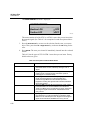
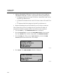
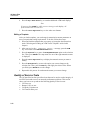
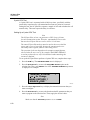
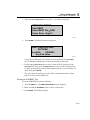
When the tests are completed, you hear a "beep" and see the AUTOTEST SUMMARY
display, which looks like this:
AUTOTEST SUMMARY
------------------------ATM Detected:
OK
Background:
UNAS
za007f.eps
From this display, you can access any of the OC3port Plus menus. See "Accessing
a Menu", which follows in this chapter.
2-12
Getting Started
Getting Acquainted with the OC3port Plus Menus
2
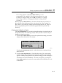
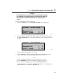
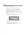
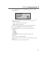
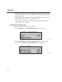
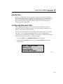
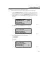
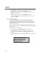
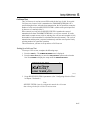
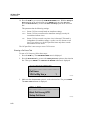
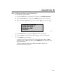
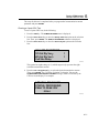
Accessing a Menu
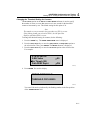
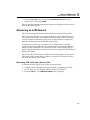
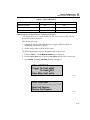
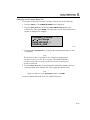
You can access any OC3port Plus menu by simply pressing one of the six direct
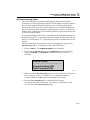
access keys located under the LCD. For example, press the OPTIONS key. The
OC3port Plus displays the following:
OPTION
SELECTIONS
----------------------Parameter Set
1
RS-232 Speed
96
za008f.eps
The display has four lines of information:
•
Line 1 contains the menu title, which in this example is named OPTIONS
SELECTIONS.
•
Line 2 is a dashed line. Depending on its location, this line indicates where
you are on a menu. If the line appears directly under the menu title, as it does
in this example, it is the top-of-menu bar. If it appears at the bottom of the
menu, it is the end-of-menu bar.
•
Line 3 is the selection line. The arrow (È) to the left of the option means that
it can be selected or changed (when you are in edit mode). To the right of the
option is a greater-than symbol ("), which is followed by a . A greater-than
symbol can be followed by a number, a word, or a three-letter abbreviation,
which is the current value of the option. In this example, the current value for
the Parameter Set option is .
•
•
Note
When you press the Left or Right Arrow key to change the setting of an option
that has a greater-than symbol (") after it, that new setting takes effect
immediately.
Line 4 displays the next item on the menu, which in this case is the RS-232
Speed option
The OC3port Plus main menus contain a variety of items. These include:
•
Options
These present choices for you to make when programming
the OC3port Plus
•
Actions
These let you perform a test or setup function; for example,
Start BERT or Setup RX Filtrs.
•
Test items
These let you start or monitor test results
2-13
OC3port Plus
Users Manual
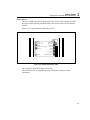
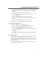
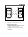
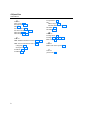
Figure 2-5 is an illustration of the OC3port Plus menu system. All of the tester’s
functions are accessed through this menu system. On the first level is the
introductory display, which is the display you see when you first turn on or reset
the tester. On the second level are the six direct access keys. These keys control the
operation of the entire tester. When you press any one of these keys, you gain
direct access to the selected function and any of its related subfunctions.
FLUKE CORPORATION
OC3port+ 3.3
03-14-99 7:22:10 PM
SELECT MENU FUNCTION
Press ESC twice
to reset the OS3port+
SONET
SONET
SELECTIONS
Laser
Moniter STS-3c
Insert Errors
Setup STS-3c
Pointer Actions
Loopback STS-3c
ATM
ATM
SELECTIONS
Moniter ATM
Setup RX Filtrs
Setup XMIT Streams
Load XMIT Streams
ATM XMIT Mode
Cell Capture
Quality of Service
OAM Transmit
OAM Moniter
ATM Options
Load Temp Trfc Only
Load Temp Trfc & Hdr
BERT
AUTO
ALARMS
OPTIONS
BERT
SELECTIONS
AUTO
SELECTIONS
ALARM
SELECTIONS
OPTIONS
SELECTIONS
Start BERT
Select BERT Pat
Setup Error Inj
IP Ping
AAL Type Detect
Auto Store
ATM Activity Scan
Start Auto Test
Review Auto Test
Section LOS
Line AIS
Line FERF
Path AIS
Path FERF
Path YELLOW
LOS Action
View Alarm Log
Parameter Set
RS-232 Speed
Scroll Method
Set Buzzer
Factory Defaults
User Info
General Info
Modem Init String
Date Time Editor
Beep Alarm/Err
Auto Test Featre
za009f.eps
Figure 2-5. OC3port Plus Menu System (Version 3.3)
Using the Directional Arrow Keys
You use the directional arrow keys to scroll through OC3port Plus menus and,
where applicable, to change parameters or edit values for options. There are four
arrow keys, each named for the direction in which they point: the Up Arrow key,
the Down Arrow key, the Left Arrow key, and the Right Arrow key.
Scrolling through Menu Options
The Up and Down Arrow keys are used to scroll through the options listed on
OC3port Plus menus.
2-14
Getting Started
Getting Acquainted with the OC3port Plus Menus
2
Note
The scrolling behavior of the Up and Down Arrow keys is userprogrammable. The examples in this book assume that you are using
the default scrolling method, which is WIN (for Windows). To change
this scrolling method, see "Changing the Default Scrolling Method"
in Chapter 3.
When you press the Down Arrow key, the menu selection that was previously on
the fourth line of the display moves up to the selection line. If you continue to
press this key, you eventually reach the end-of-menu bar, and the unit "beeps" if
you try to go past this point. To scroll in the opposite direction, press the Up
Arrow key.
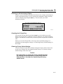
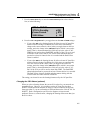
Changing the Setting for an Option
The Left and Right Arrow keys are used to change the settings for options found on
OC3port Plus menus. The following example shows you how to use these keys to
change the setting for an option.
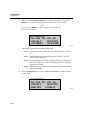
1. Press the Up or Down Arrow key to move the option whose setting you want to
change to the selection line. For example:
OPTION
SELECTIONS
----------------------Parameter Set
1
RS-232 Speed
96
za008f.eps
Note that the Parameter Set option is on the selection line as indicated by the
arrow to its left.
2. Press the Left or Right Arrow key. Notice that the value of the current setting
(in this example, the ) changes to one of the other available settings for this
option. Continue pressing the arrow key until the setting you want is displayed.
The change takes effect immediately. The value you display by pressing the
or Right Arrow key becomes the current setting for the option that is on the
selection line.
Left
2-15
OC3port Plus
Users Manual
Editing the Setting for an Option
Some settings for an option require you to supply a value rather than select an item
from a menu. You do this by editing the current value of the setting. This example
shows you how to edit a setting.
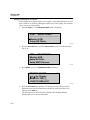
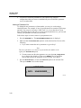
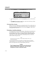
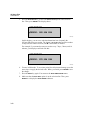
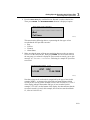
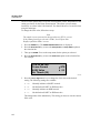
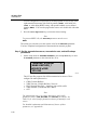
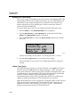
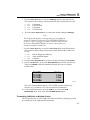
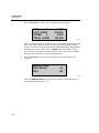
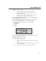
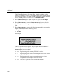
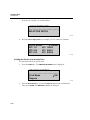
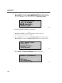
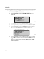
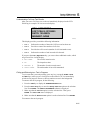
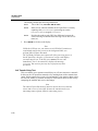
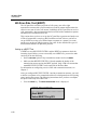
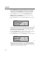
1. Press the ATM key. The ATM SELECTIONS menu is displayed:
ATM
SELECTIONS:
----------------------Monitor ATM
Setup RX Filters
za010f.eps
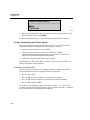
2. Press the Down Arrow key until the Setup RX Filtrs option is on the selection
line, as in:
ATM
SELECTIONS:
Monitor ATM
Setup RX Filtrs
Setup XMIT Streams
za011f.eps
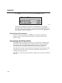
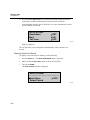
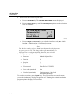
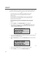
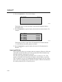
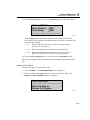
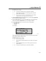
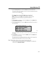
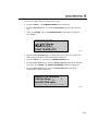
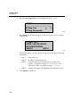
3. Press ENTER. You see the RECEIVE FILTER 1 submenu:
RECEIVE FILTER:
or for Change
NAME:FILTER_1_
LOAD TX HDR TX1
1
za012f.eps
4. Press the Down Arrow key until the VCI setting is on the selection line (as
indicated by the blue directional arrows located on each side of the LCD).
Then, press the EDIT key.
The first character of the VCI field is flashing. This flashing character
indicates that you are now in Edit mode.
2-16
Getting Started
Getting Acquainted with the OC3port Plus Menus
2
5. Press the Up or Down Arrow key until the value you want in the first position of
the VCI field is displayed. Then, press the Right Arrow key to move to the next
position.
6. Continue pressing the Up or Down Arrow key to display the desired value and
the Right Arrow key to move to the next position in the field.
7. When you are finished making changes, do one of the following:
a. Press the ENTER key. You exit Edit mode. The tester saves your changes.
b. Press the EDIT key. You exit Edit mode. The tester does not save your
changes and restores the original value.
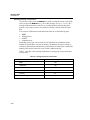
Accessing OC3port Plus Submenus
Many options on the OC3port Plus menus have an extended menu or submenu that
you have to access when you need to change their parameters. Some of the
OC3port Plus tests, for example, have many parameters, so to modify these, you
may have to access a submenu.
Typically, any option on a menu that appears by itself (that is, with no setting to its
right) has an additional menu (submenu) associated with it.
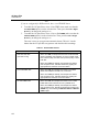
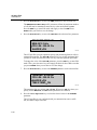
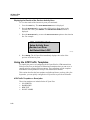
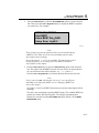
The following example shows you how to access an OC3port Plus submenu.
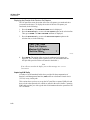
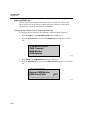
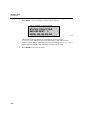
1. Press the SONET direct access key. The SONET SELECTIONS main menu is
displayed. For example:
SONET
SELECTIONS
----------------------Monitor STS-3c
Insert Errors
za013f.eps
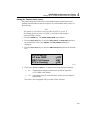
2. Press the Down Arrow key until the Setup STS-3c option is on the selection line
as in the following:
SONET
SELECTIONS
Insert Errors
Setup STS-3c
Pointer Actions
za014f.eps
2-17
OC3port Plus
Users Manual
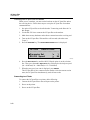
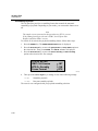
3. Press ENTER. You are now accessing the STS-3c SETUP submenu:
STS-3c SETUP:
----------------------Path Auto YEL
OFF
Line Auto FERF
OFF
za015f.eps
This submenu contains all of the STS-3c setup parameters. You navigate
through this and all other submenus by pressing the Up or Down Arrow key to
move an option to the selection line and then pressing the Left or Right Arrow
key to choose a value for the option.
Exiting OC3port Plus Submenus
To leave a submenu, simply press the ESC key to return to the introductory
display, or press any one of the direct access keys to begin a specific test or
perform a setup.
Connecting the OC3port Plus
Depending on the specific physical interface, the OC3port Plus is designed to be
connected to either intermediate-range, single-mode fiber systems, multi-mode
fiber optic systems, or unshielded twisted pair-155 systems. A single-mode
OC3port Plus uses fiber optic connectors located on the top of the tester.
The multi-mode version of the OC3port Plus is designed to be connected to multimode fiber systems. This version uses the SC Duplex fiber-optic connectors
located on the top of the tester.
The UTP-155 version of the OC3port Plus is designed to be connected to UTP-155
networks.
2-18
Getting Started
Connecting the OC3port Plus
2
Connecting the OC3port Plus to Network Devices
You need the appropriate type of cable to connect the OC3port Plus to network
devices. You can contact Fluke to obtain a variety of fiber optic and UTP cables.
Warning
Do not move the fiber connectors from side to side as you
insert them into the receptacles. Doing so can cause the
alignment ferrule to break.
1. To receive signals from network devices, connect the fiber optic cable to the
OC3port Plus IN jack.
2. To send signals on the line, connect the fiber optic cable to the OC3port Plus
OUT jack.
To create a loopback situation, complete both steps.
Connecting to Remote Devices
The OC3port Plus provides two methods of making remote (RS-232) connections:
direct and modem. The direct method allows you to connect the OC3port Plus to a
PC. You can then use the PC to control the OC3port Plus or to print test results. If
you prefer this type of connection, the PC must have the appropriate software to
control these functions. Contact Fluke Corporation for a programming book or
information about the Testview package.
As an alternative, you can use the RS-232 line to connect the OC3port Plus to a
modem. After these connections are made, you must set the baud rate from the
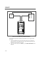
OC3port Plus and change the communication settings from the receiving device.
Connecting the OC3port Plus to a PC or Laptop
To connect the OC3port Plus to a PC or laptop computer, do the following:
1. Connect the RS-232 line to the OC3port Plus.
2. Connect the other end to the computer serial port. If the computer has a DB-9
connector, use a DB-25-to-DB-9 converter.
3. Turn on the OC3port Plus.
4. Start the appropriate PC software.
2-19
OC3port Plus
Users Manual
Connecting the OC3port Plus to a Modem
When you use a modem, you must set the baud rate on the OC3port Plus and on
the receiving device. Follow these steps to set up the OC3port Plus for modem
communications:
1. Set up the OC3port Plus as described under "Connecting to the Network" in
this chapter.
2. Use the RS-232 line to connect the OC3port Plus to the modem.
3. Make the necessary hardware and software connections on the receiving end.
4. Turn on the OC3port Plus. Wait until the self-test ends (when the tester
"beeps").
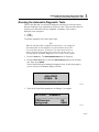
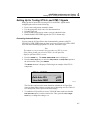
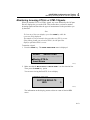
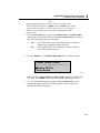
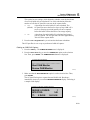
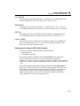
5. Press the OPTIONS key. The OPTION SELECTIONS menu is displayed:
OPTION
SELECTIONS
----------------------Parameter Set
1
RS-232 Speed
96
za008f.eps
6. Press the Down Arrow key until the RS-232 Speed option is on the selection
line. Then, press the Left or Right Arrow key to display the desired port speed
(96 = 9600 baud; 24 = 2400 baud; or 12 = 1200 baud).
7. When the port speed you want is displayed, press ENTER.
The OC3port Plus is now connected to the modem. After the remote session
starts, the OC3port Plus simultaneously sends all test results.
Connecting to a Printer
To connect the OC3port Plus to a printer, do the following:
1. Connect the OC3port Plus to the serial port on the printer.
2. Power on the printer.
3. Power on the OC3port Plus.
2-20
Getting Started
Connecting the OC3port Plus
2
Connecting to an External Power Supply
The power supply allows you to recharge the tester’s battery.
When the OC3port Plus is connected to an AC outlet, you can also use the power
supply as a continuous power source. In this way, you can test for long periods of
time without worrying about batteries.
To connect the OC3port Plus to an AC outlet, follow these steps:
1. Plug the power cable into an AC outlet.
2. Connect the power supply jack to the 5V DC outlet on the OC3port Plus.
Turn on the OC3port Plus and begin usage.
2-21
OC3port Plus
Users Manual
2-22
Chapter 3
Setting Up and Operating
the OC3port Plus
Contents
Introduction.....................................................................................................
Programming the Overall Operation of the OC3port Plus ..............................
Changing the Default Scrolling Method ...................................................
Turning on the Warning Buzzer ...............................................................
Setting the System Date and Time............................................................
Setting the Communications Speed ..........................................................
Turning Off the Automatic Diagnostic Tests............................................
Parameter Sets ..........................................................................................
Creating a Parameter Set ......................................................................
Naming a Parameter Set .......................................................................
Switching to a Different Parameter Set ................................................
Editing a Parameter Set ........................................................................
Performing Basic Operations ..........................................................................
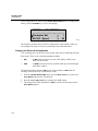
Turning on the OC3port Plus....................................................................
Turning on the Laser Transmitter .............................................................
Returning to the Introductory Display ......................................................
Resetting the OC3port Plus ......................................................................
Restoring Factory Default Settings...........................................................
Clearing the Error Counters......................................................................
Responding to Low Battery Warnings......................................................
Obtaining Information about Your OC3port Plus.....................................
Storing and Retrieving Test Results .........................................................
Manually Storing Test Results .............................................................
Automatically Storing Test Results in Memory ...................................
Displaying Stored Test Results ............................................................
Deleting Stored Test Results ................................................................
Deleting a Single Record......................................................................
Deleting All Stored Records in a Test Group.......................................
Printing, Downloading, and Remote Control ...........................................
Page
3-3
3-3
3-4
3-5
3-5
3-6
3-7
3-8
3-8
3-10
3-11
3-11
3-12
3-12
3-14
3-15
3-15
3-15
3-16
3-16
3-17
3-17
3-18
3-19
3-22
3-24
3-25
3-25
3-26
3-1
OC3port Plus
Users Manual
Connecting to the Serial Port................................................................
Printing Reports and Configuration Information..................................
Pausing a Print Job ...............................................................................
Preventing a Report from Being Printed ..............................................
Controlling the OC3port Plus Remotely...................................................
Running the Automatic Diagnostic Tests........................................................
3-2
3-26
3-29
3-30
3-30
3-30
3-31
Setting Up and Operating the OC3port Plus
Introduction
3
Introduction
This chapter covers the basics of setting up and operating the OC3port Plus. The
first section shows you how to program the overall operation of the tester to
configure such elements as the scrolling method and the status of the key beeping
mechanism and how to set the date and time. It also shows you how to create
parameter sets so that you can store different but commonly used configurations in
separate groups and switch quickly between groups.
The second section covers basic OC3port Plus operations. You learn how to turn
on the unit and perform such fundamental tasks as clearing the display, resetting
the unit, storing and retrieving test results, and running diagnostic tests.
Programming the Overall Operation of the OC3port Plus
The OC3port Plus has a number of programmable setup options that enable you to
determine its overall operating characteristics. Any settings that you choose for
these options when you configure the OC3port Plus are stored in internal memory
so that even when you shut off the tester, you do not lose valuable configuration
information.
Following is a list of OC3port Plus setup options available for you to change:
•
Scroll method
Determines the behavior of the arrow keys when you scroll through menus.
•
Buzzer operation
Enables/disables the sounding of a warning buzzer whenever you press an
invalid key.
•
Date/time setting
Sets the system date and time.
•
Communications speed
Sets the baud rate.
•
Automatic tests
Enable/disable the execution of a series of automatic diagnostic tests when you
power on the tester.
•
Parameter sets
Store two different configuration sets under the respective labels, Parameter
Set 1 and 2.
3-3
OC3port Plus
Users Manual
These setup options are found on the OPTION SELECTIONS menu. To display this
menu, press the OPTIONS key. You see this display:
OPTION
SELECTIONS
----------------------Parameter Set
1
RS-232 Speed
96
za008f.eps
The following sections show you how to change these setup options so that you
can configure the tester to suit your personal style and work preferences:
Changing the Default Scrolling Method
You can change the way the arrow keys operate when you scroll through OC3port
Plus menus. There are two scrolling methods available:
•
WIN
In WIN mode, the arrow keys move the display window up or
down over the menus.
•
ARW
In ARW mode, the arrow keys pull the menu up or down through
the display window.
The default scrolling method is WIN. If you want to change to ARW mode for
scrolling, follow these steps: (for Windows) mode
1. From the OPTION SELECTIONS menu, press the Down Arrow key to move the
Scroll Method option to the selection line.
2. Press the Left or Right Arrow key to display the ARW setting.
3. The change takes effect immediately. ARW is now the current setting for the
Scroll Method option.
3-4
Setting Up and Operating the OC3port Plus
Programming the Overall Operation of the OC3port Plus
3
Turning on the Warning Buzzer
The OC3port Plus has a warning buzzer that causes the unit to issue a "beep" when
you try to go beyond the top-of-menu or end-of-menu bar, or when you press the
MEMORY key to store information in the tester’s memory. This buzzer is controlled
by the Set Buzzer option, which can be set to ON or OFF (the default).
To turn on the warning buzzer, do the following:
1. From the OPTION SELECTIONS menu. Then, press the Down Arrow key to
move the Set Buzzer option to the selection line.
2. Press the Left or Right Arrow key to change the setting for this option to ON.
The change takes effect immediately. The warning buzzer is now activated.
Setting the System Date and Time
The DateTime Editor is used to set the internal clock on the OC3port Plus. With
this editor, you can set the date in month : day : year format and the time in
hour : minute : time-of-day format. The tester uses the date and time you supply to
time-stamp stored test results and alarm information.
To set the date and time, follow these steps:
1. From the OPTION SELECTIONS menu, press the Down Arrow key to move the
DateTime Editor option to the selection line.
2. Press ENTER. The SET DATE and TIME submenu displays. For example:
SET DATE and TIME
----------------------MONTH JUN
DATE:07
za016f.eps
3. Press the EDIT key to enter Edit mode. The current setting for MONTH flashes.
Press the Up or Down Arrow key to display the desired month. Then, press
ENTER to save your selection.
3-5
OC3port Plus
Users Manual
4. Press the Down Arrow key to move DATE to the selection line. Then, press the
EDIT key. The number in the first position of the DATE field flashes.
Press the Up or Down Arrow key to display the desired number. Then, press the
Right Arrow key to move to the next position and enter the desired value there.
Finally, press ENTER to save your selection.
5. Press the Down Arrow key to move YEAR to the selection line. Press the EDIT
key to enter Edit mode and make the necessary changes. Make sure you press
ENTER when you are done to save the change.
6. Press the Down Arrow key to move TIME to the selection line. Press the EDIT
key to enter Edit mode and set the time. When you finish, press ENTER to save
your selection.
7. The tester is now configured with your date and time selections.
Setting the Communications Speed
To set the communications speed on the OC3port Plus, complete these steps:
1. From the OPTION SELECTIONS menu, press the Down Arrow key to move the
RS-232 Speed option to the selection line:
OPTION
SELECTIONS
Parameter Set
1
RS-232 Speed
96
Scroll Method
WIN
za017f.eps
This option has these three settings:
•
96
9600 baud
•
24
2400 baud
•
12
1200 baud
2. Press the Left or Right Arrow key to select the correct communications speed.
The change takes effect immediately. The OC3port Plus is configured with the
baud rate you selected.
3-6
Setting Up and Operating the OC3port Plus
Programming the Overall Operation of the OC3port Plus
3
Turning Off the Automatic Diagnostic Tests
When you first power on the OC3port Plus, it automatically conducts a series of
self-tests and diagnostic tests that assess the basic health of any OC3 signal
provided to its input connector. If no signal is present or if theOC3port Plus is not
yet connected to a network, the tester waits until a signal is detected.
After a signal is detected, the OC3port Plus begins a 25-second analysis of the
signal and its format. Then, the OC3port Plus displays a set of summary statistics
for both ATM and SONET. For information on the results provided by these tests,
see "Running the Automatic Diagnostic Tests" later in this chapter.
The automatic tests are conducted and results are displayed every time you power
on the OC3port Plus unless you prevent the tester from running them. The
instructions in this section show you how to do this.
Note
You can run the automatic tests under your own control. For
information on how to do this, see "Running the Automatic
Diagnostic Tests" later in this chapter.
If you want to prevent the OC3port Plus from running the diagnostic tests every
time you turn on the tester, do the following:
1. From the OPTION SELECTIONS menu, press the Down Arrow key until the
AutoTest Featre option is on the selection line:
OPTION
SELECTIONS
Beep Alarm/Err
OFF
Auto Test Featre
ON
----------------------za018f.eps
2. Press the Left or Right Arrow key to change the setting for this option to OFF.
The change takes effect immediately. The OC3port Plus does not perform the
automatic tests when you power on the unit.
3-7
OC3port Plus
Users Manual
Parameter Sets
The OC3port Plus can store in memory up to two distinct groups of user-defined
configurations under the respective labels Parameter Set 1and 2. Each group can
contain any of the programmable options available on the OC3port Plus. These
include any setups you create, the parameters and settings for tests, transmission
modes, ATM states, and BERT test patterns, to name a few.
Parameter sets are useful when you need to retain test setups and configurations
that you use frequently. For example, you can create one parameter set for BERT
testing and the other for ATM testing. Parameter sets are also useful when more
than one person uses the unit. Each user can store his or her own user definitions
for tests and setups in a separate parameter set.
You can use only one parameter set at any given time, but you can easily switch to
the other set and begin using its setups.
This section shows you how to do the following:
•
Create a parameter set
•
Name a parameter set
•
Switch between parameter sets
•
Edit a parameter set.
Creating a Parameter Set
Note
When you turn on the OC3port Plus, it uses the parameter set that
was in use when the unit was last turned off. If this is the first time
that you are using the tester, the parameter set that is active when
you turn on the unit is Parameter Set 1.
To find out what parameter set you are currently in, press the
OPTIONS key to display the OPTION SELECTIONS menu. Scroll
through the list until you see the Parameter Set option. The number to
the right of this option indicates which parameter set you are
currently in.
3-8
Setting Up and Operating the OC3port Plus
Programming the Overall Operation of the OC3port Plus
3
Caution
Be careful when you restore the factory defaults because
any settings and configurations you previously stored in
Parameter Sets will be replaced by the factory default
values.
To create a parameter set, do the following:
1. Press the OPTIONS key. The OPTION SELECTIONS menu is displayed:
OPTION
SELECTIONS
----------------------Parameter Set
1
RS-232 Speed
96
za008f.eps
2. Make sure that the Parameter Set option is on the selection line. Then, press
the Left or Right Arrow key to select the parameter set you want to create. For
example:
OPTION
SELECTIONS
----------------------Parameter Set
2
RS-232 Speed
96
za019f.eps
In this example, Parameter Set 2 is selected.
3. Press the ENTER key. The tester resets itself and activates the parameter set
you selected. In this example, Parameter Set 2 is now activated.
Note
To make sure that the parameter set you selected is the active one,
press the OPTIONS key again. The number of parameter set that is
currently active is displayed to the right of the Parameter Set option.
In this example, the setting for the Parameter Set option is 2, which indicates
that Parameter Set 2 is the active parameter set.
3-9
OC3port Plus
Users Manual
4. You can now create the parameter set you selected. Any setups or
configurations that you create are automatically stored within this parameter
set as you make them.
Naming a Parameter Set
To distinguish one parameter set from another, you can give each a unique,
identifying name. For example, if one of your parameter sets contains ATM setups
and tests, you can give it the name "ATM Tests". Or, if you share the OC3port
Plus with another person and each of you has created a parameter set, you can each
identify your parameter set with your own name.
Follow these steps to create a name for your parameter sets.
1. Press the OPTIONS key. The OPTION SELECTIONS menu is displayed.
2. Make sure that the Parameter Set option is on the selection line. Do one of the
following:
a. If you want to name the active parameter set, go to Step 3.
Note
The active parameter set is the one represented by the number to the
right of the Parameter Set option.
b. If want to name one the other parameter set, press the Left or Right Arrow
key to display the desired set. Then, press ENTER. The OC3port Plus
reboots and activates the parameter set you selected. Go to Step 3.
3. Press the Down Arrow key to move the User Info option to the selection line.
Then, press ENTER. You see this display:
USER INFO
INFO:
UNASSIGNED_ _
za020f.eps
3-10
Setting Up and Operating the OC3port Plus
Programming the Overall Operation of the OC3port Plus
3
You are in Edit mode as indicated by the flashing "U" in the first position of
the INFO field. The name UNASSIGNED is the default name assigned to each
parameter set.
The name you choose can be one to ten characters long.
4. Press the Up or Down key to display the desired letter or number in the first
position of the INFO field.
5. Then, press the Right Arrow key to move to the next position.
6. Continue pressing the arrow keys in this manner until the name you want is
displayed.
7. When you finish, press ENTER to save the newly created name.
Complete this procedure for each parameter set that you want to name.
Switching to a Different Parameter Set
To switch to the other parameter set, follow these steps:
1. Press the OPTIONS key. The OPTION SELECTIONS menu is displayed.
2. Make sure that the Parameter Set option is on the selection line.
3. Then, press the Left or Right Arrow key to display the number of the parameter
set that you want to switch to.
4. Press ENTER.
The OC3port Plus immediately reboots and switches to the parameter set that
you selected.
Editing a Parameter Set
When you change the setting for an option or re-configure a setup, those changes
are automatically stored in the parameter set that is currently active.
Therefore, when you want to edit a parameter set, first activate the parameter set
that you want to edit. (See "Creating a Parameter Set" if you need to know how to
activate a parameter set.)
Then, make the desired changes, which the OC3port Plus automatically stores in
the parameter set you are working in.
3-11
OC3port Plus
Users Manual
Performing Basic Operations
You need to know some fundamental things about how to operate the OC3port
Plus before you can start configuring the unit to perform tests or acquiring test
results.
In this section, you learn how to turn on the unit then how to do essential tasks that
you will need to operate the OC3port Plus.
Turning on the OC3port Plus
The OC3port Plus has an ON/OFF switch built into the membrane keypad.
This switch is located in the lower right corner as shown in Figure 3-1.
PRINT
MEMORY
CLEAR
DELETE
ESC
za005f.eps
Figure 3-1. OC3port Plus ON/OFF switch
3-12
Setting Up and Operating the OC3port Plus
Performing Basic Operations
3
To turn on the OC3port Plus, do the following:
1. Press the ON/OFF switch.
The OC3port Plus performs a series of automatic self-tests and other signal
verification tests. When these tests are completed, all of the status LEDs on its
front panel light. The unit "beeps" and you see a display similar to the
following:
AUTOTEST SUMMARY
------------------------ATM Detected:
OK
Background:
UNAS
za007ff.eps
Note
If you want to prevent the OC3port Plus from performing these
automatic tests, see "Turning Off the Automatic Diagnostic Tests" in
this chapter. If you want information about this test and the types of
results it provides, see "Running the Automatic Diagnostic Tests"
also in this chapter.
2. You can now press any one of the direct access keys to select tests or set up
configurations.
Note
If you are using a single-mode OC3port Plus, the first line of the
display flashes a *LASER OFF* message if you power on the unit
with no input signal present. If you want to perform tests that use the
SONET transmitter, you must turn the laser on. For information on
how to do this, see "Turning on the Laser Transmitter" in this
chapter.
3. When you finish using the unit, press the ON/OFF switch.
The OC3port Plus shuts off and saves all of your setup information in its
internal memory.
3-13
OC3port Plus
Users Manual
Turning on the Laser Transmitter
Notes
This procedure applies only if you are using a single-mode OC3port
Plus.
When the laser transmitter is off, the top line of all OC3port Plus
flashes the *LASER OFF* message, and the STATUS LED blinks.
After you turn on the transmitter, the message disappears and the
STATUS LED emits a steady green light.
When you first turn on the single-mode version of the OC3port Plus, the laser
transmitter may be set to OFF. If you want to transmit, you must set the transmitter
to ON.
To turn the laser on, follow these steps.
1. Press the SONET key. The SONET SELECTIONS menu is displayed. For
example:
SONET
SELECTIONS
----------------------Laser
OFF
Monitor STS-3c
za022f.eps
2. The Laser option is on the selection line. In this example, notice that the
setting is OFF.
3. Press the Right Arrow key to change the setting to ON.
The change takes effect immediately. The *LASER OFF* message
disappears, indicating that the transmitter is now on.
3-14
Setting Up and Operating the OC3port Plus
Performing Basic Operations
3
Returning to the Introductory Display
Whenever you are finished with a particular function (for example, monitoring test
results or performing setups), you can return to the introductory display from any
menu or submenu by pressing the ESC key. The unit returns you to this
introductory display:
FLUKE CORPORATION
OC3port+
3.3
03-14-99
7:22:10 PM
SELECT MENU FUNCTION
za023f.eps
Resetting the OC3port Plus
You reset the OC3port Plus by pressing the ESC key twice within one second.
When you reset the tester, it performs a self-test and leaves you at the introductory
display. This function is useful when you want to put the OC3port Plus in a known
state.
When you reset the OC3port Plus, it does not restore the default settings. For
information on restoring these settings, see "Restoring Factory Default Settings" in
this chapter.
Restoring Factory Default Settings
You can reset the OC3port Plus so that the settings for menu options are the same
as they were when the unit was shipped from the factory. To restore the factory
default settings, follow these steps:
Caution
Be careful when you restore the factory defaults because
any settings and configurations you previously stored in
Parameter Sets 1 through 4 are replaced by the factory
default values.
3-15
OC3port Plus
Users Manual
1. Press the OPTIONS key. The OPTION SELECTION menu is displayed:
OPTION
SELECTIONS
----------------------Parameter Set
2
RS-232 Speed
96
za019f.eps
2. Press the Down Arrow key until the Factory Defaults option is on the selection
line:
3. Press ENTER. The unit issues a short "beep" and resets to the factory defaults.
You return to the introductory display.
Clearing the Error Counters
If there are errors on a signal, they are presented on the LCD. As certain errors are
detected, the counters on the display continuously increase. To clear the display of
any errors and reset the error counter to zero, press the CLEAR key while you are
viewing the errors on the LCD.
Responding to Low Battery Warnings
The OC3port Plus uses NiCad internal batteries. These batteries last for about one
year. When the battery charge is low, the OC3port Plus issues periodic "beeps"
and then displays a LOW BATTERY warning on the LCD. When this situation
occurs, the unit has approximately five minutes of battery power remaining. We
suggest that you use the remaining time to immediately store any current test
results and then recharge the unit.
Note
If the battery does not charge, contact Fluke Customer Service for
replacement batteries.
You can connect the tester to the supplied AC adapter/charger and charge it
without shutting it off. On a full battery charge, which takes between 12 to 14
hours, the OC3port Plus will run for approximately three hours.
Caution
The AC adapter/charger should never be disconnected
while the OC3port Plus is powered on. This can cause
corruption of current or stored test results.
3-16
Setting Up and Operating the OC3port Plus
Performing Basic Operations
3
Obtaining Information about Your OC3port Plus
If you ever require technical assistance you will need to provide certain
information about your OC3port Plus, such as the software revision number, serial
number, and model type. This procedure shows you how to obtain this and other
pertinent information about your OC3port Plus.
1. Press the OPTIONS key. The OPTIONS SELECTIONS menu is displayed.
2. Press the Down Arrow key to move the General Info option to the selection
line. Then, press ENTER. You see a display similar to the following:
GENERAL INFO
-----------------------SOFTWRE REV: 3.3
MODEL TYPE :OC3-P1
za025f.eps
This display contains the following information:
•
•
•
•
•
•
7SJX[EVIVIZMWMSRRYQFIV
1SHIPX]TI
0MWXSJMRWXEPPIHSTXMSRW
8VERWGIMZIVX]TI WMRKPIQSHIQYPXMQSHISV984
)PIGXVSRMGWIVMEPRYQFIV
Remote (indicates whether your unit is enabled or disabled for remote
control).
Storing and Retrieving Test Results
You can store results from the many OC3port Plus tests in memory for later use
and review. These results remain in memory even after you shut off the unit. This
section shows you how to do the following:
•
•
•
•
7XSVIXIWXVIWYPXWQERYEPP]ERHEYXSQEXMGEPP]
(MWTPE]WXSVIHXIWXVIWYPXW
(IPIXIWXSVIHXIWXVIWYPXW
Print stored test results.
Using the Auto Store option, you can program the OC3port Plus to automatically
store test results in memory as they are acquired. The Auto Store option can also be
used to automatically send test results periodically to the printer. This section also
shows you how to set up the OC3port Plus for automatic test storage.
3-17
OC3port Plus
Users Manual
Manually Storing Test Results
To store test results, press the MEMORY key while viewing the results on the LCD.
After you press the MEMORY key, you see this message: RECORD SAVED. This
message indicates that the result you are viewing has been stored in the tester’s
memory. Any results you store are retained even after you turn off the OC3port
Plus.
You can store LED status records and results from any of the following tests:
•
•
•
•
&)68
%81'IPPPSWW
732)8
Automatic tests.
Depending on the type of test record, the OC3port Plus has a limitation on the
number of records that it can store in memory. In addition, the tester’s storage is
circular so that when the limitation for a particular test is reached, the record at the
bottom of the stack is deleted as a new record is added to the top.
Table 3-1 provides a list of storage limitations for each group of test records that
you can store:
Table 3-1. Storage Limits for Test Records
Test Records
3-18
Storage Limit
BERT
100
LED Status
100
ATM cell loss
128
Alarm
128
Counters
32
Automatic diagnostic tests
10
Setting Up and Operating the OC3port Plus
Performing Basic Operations
3
Automatically Storing Test Results in Memory
In this procedure, you will set up the OC3port Plus to automatically store test
results. This entails selecting which test results to store and setting the timing
criteria which determines how frequently those results are collected and stored.
To set up the OC3port Plus to automatically collect and store test results:
1. Press the AUTO key to display the AUTO SELECTIONS menu.
2. Press the Down Arrow key to move the Auto Store to the selection line. Then,
press ENTER. The AUTO STORE submenu is displayed, as in the following:
option
AUTO STORE:
-----------------------Auto Store
OFF
Select Period
za026f.eps
3. Make sure that the Auto Store option is on the selection line. This option has
two settings:
•
OFF
(the default)
Turns off the automatic test storage feature.
•
ON
Turns on the automatic test storage feature.
4. Press the Left or Right Arrow key to change the Auto Store setting to ON.
3-19
OC3port Plus
Users Manual
5. Press the Down Arrow key to move the Select Period option to the selection
line. Then, press ENTER. The display shows:
SET PERIOD
PERIOD: 00D 00H 01M
za027f.eps
On this display, you can set a value that determines how frequently the
OC3port Plus stores test results. The format is D / H / M, where D is the number
of days, H is the number of hours, and M is the number of minutes.
For example, if you wanted to store test results every 7 days, 5 hours, and 10
minutes, your display would look like this:
SET PERIOD
PERIOD: 07D 05H 10M
za028f.eps
6. You are in Edit mode. To set a time period for collection and storage, press the
arrow keys to supply the desired value. When, you finish, press ENTER to save
the change.
7. Press the AUTO key again. You return to the AUTO SELECTIONS menu.
8. Make sure that the Auto Store option is on the selection line. Then, press
ENTER to re-display the AUTO STORE submenu.
3-20
Setting Up and Operating the OC3port Plus
Performing Basic Operations
3
9. Press the Down Arrow key to move the Destination option to the selection line,
as in the following:
AUTO STORE:
Select Period
Destination
Bert
PRT
OFF
za029f.eps
This option determines where the OC3port Plus sends the test results. This
option has three settings:
•
PRT
Sends results to an attached printer.
•
MEM
Stores results in memory.
•
BTH
Sends results to an attached printer and stores them in memory.
10. Press the Left or Right Arrow key to choose the desired destination.
11. Press the Down Arrow key to move each of the following options to the
selection line:
•
•
•
•
Bert
Cell Loss
Counters
Alarm Status
These options determine which test records the OC3port Plus stores
automatically.
Each option has two settings, ON and OFF.
When set to ON, test records for the selected option are automatically collected
and stored.
When set to OFF, no records are automatically stored.
3-21
OC3port Plus
Users Manual
12. Press the Left or Right Arrow key to choose the desired setting for each test
record that you want to automatically collect and store records for.
In the following example, the OC3port Plus is set up to automatically collect
and store BERT test records.
AUTO STORE:
Destination
Bert
Cell Loss
PRT
ON
OFF
za030f.eps
Setup is completed.
The OC3port Plus is now configured to automatically collect and store test
records.
Displaying Stored Test Results
To display test results stored in memory, do the following:
1. Press the AUTO key. The AUTO SELECTIONS menu is displayed.
2. Make sure that the Auto Store option is on the selection line.
3. Then, press ENTER.
The AUTO STORE submenu is displayed:
AUTO STORE:
-----------------------Auto Store
OFF
Select Period
za026f.eps
3-22
Setting Up and Operating the OC3port Plus
Performing Basic Operations
3
4. Press the Down Arrow key until the Review Records is on the selection line.
Then, press ENTER. The REVIEW RECORDS submenu is displayed: option
REVIEW RECORDS:
-----------------------Bert
Cell Loss
za031f.eps
This menu has the following choices, representing the four types of test
records that the OC3port Plus can store:
•
•
•
•
&IVX
'IPPPSWW
'SYRXIVW
Alarm Status
5. Make sure that the name of the group containing the test results you want to
review is on the selection line. Then, press ENTER. The first record stored in
the test group you selected is displayed. If no records are stored, you see this
message: NO RECORDS COLLECTED. Following is a sample OC3port Plus
test record:
BERT RECORD 5/11
6797 OOF
03-12-99
11:44:19AM
za032f.eps
Note that, when saved, each result is categorized by the type of test (in this
example, BERT). A counter to the right of the test name indicates which
record you are viewing (in this example, record 5 out of a total of 11). Line 2
of the display indicates the number and type of error recorded (in this
example, 6797 OOF). At the bottom of the display, the date and time that the
record was stored is given (in this example, the record was stored on March
12, 1996 at 11:44:19 a.m.).
3-23
OC3port Plus
Users Manual
The Left and Right Arrow keys can be used to cycle through the various display
formats available for the particular record you are reviewing. For example, by
pressing these keys, you can view these two additional displays for BERT
records stored in memory:
BERT RECORD 5/11
1.00E-03
BER
3.016E+05 ERRORS
3.016E+08 BITS
za033f.eps
BERT RECORD 5/11
5 E/S
1 ESEC
0 THSEC
za034f.eps
Press the Up or Down Arrow key to view additional records that you have
stored. In this example, pressing the Up or Down Arrow key allows you to see
the ten remaining BERT records.
Deleting Stored Test Results
You can delete stored test records individually or you can delete all records in a
particular group from memory.
3-24
Setting Up and Operating the OC3port Plus
Performing Basic Operations
3
Deleting a Single Record
To delete a single test record, follow these steps:
Caution
Be careful when you delete a stored test record. Deleting
a stored test record cannot be undone.
1. Press the AUTO key to display the AUTO SELECTIONS menu.
2. Make sure that the Auto Store option is on the selection line. Then, press
ENTER. The AUTO STORE submenu is displayed.
3. Press the Down Arrow key to move the Review Records to the selection line.
Then, press ENTER. The REVIEW RECORDS submenu is displayed: option
REVIEW RECORDS:
-----------------------Bert
Cell Loss
za031f.eps
4. Move the name of the group containing the test record you want to delete to
the selection line. Then, press ENTER. The first test record in the group you
selected is displayed.
5. Press the Up or Down Arrow key to display the particular test record you want
to delete. Then, press the CLEAR key. The individual test record you selected
is deleted from the tester’s memory.
Deleting All Stored Records in a Test Group
To delete all test records in a group from storage, do the following:
Warning
Be careful when you delete a stored test record. Deleting
a stored test record cannot be undone.
1. Press the AUTO key to display the AUTO SELECTIONS menu.
2. Make sure the Auto Store option is on the selection line. Then, press ENTER.
The AUTO STORE submenu is displayed.
3. Press the Down Arrow key to move the Delete Records option to the selection
line. Then, press ENTER. The DELETE RECORDS submenu is displayed:
3-25
OC3port Plus
Users Manual
DELETE RECORDS:
-----------------------Bert
Cell Loss
za035f.eps
4. Make sure that the name of the group whose records you want to delete is on
the selection line. Then, press ENTER.
All of the tests in the group you selected are deleted from the tester’s memory.
Printing, Downloading, and Remote Control
On its connector panel, the OC3port Plus has an EIA-232 serial port, which is
designed into an RJ-11 (telephone) jack. With this port, you can:
•
Connect the OC3port Plus to a serial printer.
•
Connect the OC3port Plus to a PC that is running any standard
communications terminal program (such as Procomm or Crosstalk) and
capture test results and configuration information.
•
Control the operation of the OC3port Plus remotely.
The information in this section shows you how to set up your OC3port Plus for
printing and remote control operation.
Connecting to the Serial Port
To connect your OC3port Plus to a computer, printer, or modem you need the
following equipment, which is supplied with the OC3port Plus:
•
RJ-11 to RJ-11 cable
•
RJ-11 to DB-25s female adapter for connection to a computer
•
RJ-11 to DB-25s male adapter for connection to modems and printers
•
RJ-11 to DB-9 female adapter.
To assist you in establishing working connections, Tables 3-2, 3-3, and 3-4 are
provided, which describe the serial control signals available at the RJ-11 connector
and 25-pin computer and modem/printer connectors.
3-26
Setting Up and Operating the OC3port Plus
Performing Basic Operations
3
Table 3-2. RJ-11 Pin Descriptions
Pin
Description
Pin
Description
3
CTSClear to Send
5
TXDTransmit Data
4
RXDReceive Data
6
RTSRequest to Send
Pin
1,2
Description
GndSignal Ground
Table 3-3. Serial Port 25-pin Computer Connection Pin Descriptions
Pin
Description
Pin
2
TXDTransmit
Data
3
Description
RXDReceive
Data
Pin
4
Description
RTSRequest to
Send
Pin
5
Description
Pin
CTSClear to
Send
7
Description
GNDSignal
Ground
Table 3-4. Serial Port 25-Pin Modem/Printer Connection Pin Descriptions
Pin
Description
Pin
Description
2
RXDReceive
Data
3
TXDTransmit
Data
7
GNDSignal
Ground
20
DTRData
Terminal
Ready
Pin
Description
Pin
Description
4
CTSClear to
Send
5
RTSRequest
to Send
Pin
6
Description
DSRData Set
Ready
To connect your OC3port Plus to a printer or PC, follow these steps:
1. Plug one end of the RJ-11 to RJ-11 cable into the RS-232 jack, which is
located on the connector panel.
2. Plug the other end of this cable into the appropriate adapter.
3. Plug the adapter into the serial port on the printer or PC.
3-27
OC3port Plus
Users Manual
4. Set the baud rate on the OC3port Plus:
a. Press the OPTIONS key. The OPTION SELECTIONS menu is displayed.
b. Press the Down Arrow key until the RS-232 Speed option is on the selection
line. For example:
OPTION SELECTIONS
Parameter Set
RS-232 Speed
Scroll Method
1
96
WIN
za036f.eps
c. Press the Right or Left Arrow key to select the interface speed (96 = 9600
baud, 24 = 2400 baud, 12 = 1200 baud) you want.
Note
For the best results, select the baud rate that matches the fastest rate
on your printer or PC. The change takes effect immediately. The
OC3port Plus is configured with the baud rate you selected.
5. Configure your printer or PC as follows:
•
Baud rate
Match OC3port Plus
•
Data bits
8
•
Stop bits
1
•
Parity
None
•
Flow control
Xon/Xoff or CTS/RTS
•
Local echo (terminals)
On
•
Line feed (terminals)
Carriage return = line feed
(inbound /outbound).
To test the connection, press the ESC key. The OC3port Plus resets and returns
you to the introductory display. The printer or PC running the terminal emulation
program prints or displays OC3port Plus.
3-28
Setting Up and Operating the OC3port Plus
Performing Basic Operations
3
Printing Reports and Configuration Information
The OC3port Plus prints configuration reports and test results for reference
purposes. To obtain a printout of a report, complete these steps:
1. Press the PRINT key. The PRINT SELECTIONS menu is displayed.
PRINT SELECTIONS
-----------------------Print Mode
ON
Reports
za037f.eps
2. Leave Print Mode setting ON.
Note
We suggest that you leave the print mode setting ON (the default).
When set to ON, printing is done in the background, making it
secondary to any network testing or monitoring that is going on.
3. Press the Down Arrow key to move the Reports option to the selection line.
Then, press ENTER. You see this submenu:
REPORTS:
-----------------------Config Params
Activity Scan
za038f.eps
This menu lists the following types of reports that you can print.
•
•
•
•
•
'SRJMK4EVEQW
%GXMZMX]7GER
%PEVQ0SK
)VVSV%PEVQ-RWIVX
Auto Store Params
4EVEQIXIVWIXW
%GXMZMX]WGERVITSVXW
%PEVQPSKHEXE
)VVSVWEPEVQW
Automatic test storage parameter
4. Press the Down Arrow key to move the report that you want to print to the
selection line. Then, press the PRINT key. The report you selected begins to
print.
3-29
OC3port Plus
Users Manual
Pausing a Print Job
To pause a job that is currently printing, do the following:
1. From the PRINT SELECTIONS main menu, make sure that the Print Mode option
is on the selection line.
2. Press the Right Arrow key to display the PSE (pause) setting.
The print job temporarily stops.
Preventing a Report from Being Printed
To prevent a report from being printed, follow these steps:
1. From the PRINT SELECTIONS main menu, make sure that the Print Mode option
is on the selection line.
2. Press the Right Arrow key to display the OFF setting.
All printing is currently prevented from occurring.
Controlling the OC3port Plus Remotely
For information about remote control software, contact Fluke at:
*09/)MRXLI97%ERH'EREHE
MR)YVSTI
MR.ETER
7MRKETSVI
206-356-5500 anywhere in the world
Visit Fluke’s web site at www.fluke.com.
To connect the OC3port Plus to a modem, follow these steps:
1. Make sure that the OC3port Plus and the modem are powered off.
2. Plug one end of the RJ-11 to RJ-11 cable into the RS-232 jack, which is
located on the connector panel. Plug the other end of this cable into the RJ-11
to DB-25s adapter marked "modem/printer".
3. Plug the RJ-11 to DB-25s adapter into the serial port on the modem.
4. Connect the modem to the phone jack.
5. Turn on the modem.
6. Turn on the OC3port Plus.
3-30
Setting Up and Operating the OC3port Plus
Running the Automatic Diagnostic Tests
3
Running the Automatic Diagnostic Tests
The OC3port Plus has a set of built-in diagnostic tests that you can run to assess
the basic condition of any signal that is present on a line. These tests take about 25
seconds to run. When the tests are completed, a summary of the results is
displayed in two categories:
•
•
%81
SONET
To start the diagnostic tests, follow these steps:
Note
When the OC3port Plus is shipped from the factory, it is configured
to automatically run the diagnostic tests described in this section
every time that you power on the unit. For instructions on how to
prevent the tester from running these tests when you turn it on, see
"Turning Off the Automatic Diagnostic Tests" earlier in this chapter.
1. Press the AUTO key. The AUTO SELECTIONS menu is displayed. .
2. Press the Down Arrow key to move the Start AutoTest option to the selection
line. Then, press ENTER.
The OC3port Plus begins running the diagnostic tests. As the tests progress,
you see a series of countdown displays like this:
******************************
ANALYZING
SIGNAL 24
******************************
za039f.eps
3. Then, the OC3port Plus summarizes its findings. For example:
AUTOTEST SUMMARY
------------------------ATM Detected:
OK
Background:
UNAS
za007f.eps
3-31
OC3port Plus
Users Manual
The diagnostic test results provided by the OC3port Plus are listed in the Table
3-5. Press the Down Arrow key to scroll through the list.
Table 3-5. OC3port Plus Diagnostic Test Results for ATM and SONET
Network
ATM
Results
ATM Detected:
OK
NO
ERR
Background:
UNAS
IDLE
BOTH
OAM F4:
YES
NO
OAM 5:
YES
NO
ILMI:
SONET
YES
NO
Section:
OK
ERR
Line:
OK
ERR
Path:
OK
ERR
Pointer:
OK
LOSS
Alarms:
YES
NONE
3-32
Meaning
Indicates condition of ATM traffic detected:
• OK (if ATM cell delineation is obtained)
• NO (no ATM cell delineation)
• ERR (header checksum errors found)
Indicates type of background traffic detected:
• UNAS (unassigned cells detected)
• IDLE (idle cells detected)
• BOTH (both idle and unassigned cells detected)
Indicates whether OAM F4 cells were detected on VCI 3
or VCI 4:
• YES (detected)
• NO (not detected)
Indicates where OAM F5 cells were detected with
payload types of 4 or 5:
• YES (detected)
• NO (not detected)
Indicates where ILMI cells were detected on VCI 16:
• YES (detected)
• NO (not detected)
Indicates whether any section-level errors were found:
• OK (no section errors found)
• ERR (section errors found)
Indicates whether any line-level errors were found:
• OK (no line errors found)
• ERR (line errors found)
Indicates whether any path-level errors were found:
• OK (no path errors found)
• ERR (path errors found)
Indicates whether there is a problem with SONET pointer:
• OK (valid pointer was detected)
• LOSS (loss of pointer)
Indicates whether SONET alarms have been detected:
• YES (alarms detected)
• NONE (no alarms detected)
Chapter 4
SONET/SDH Configuration
and Testing
Contents
Introduction ....................................................................................................
Configuring the Framing Format ....................................................................
Differences between SONET OC3 STS-3c and SDH STM-1..................
Changing the Framing Format .................................................................
Changing the S-Bit Values (optional) ......................................................
Setting Up for Testing STS-3c and STM-1 Signals........................................
Generating Automatic Alarms..................................................................
Setting the Transmit Clock Source...........................................................
Scrambling Payloads................................................................................
Changing the Threshold Setting for Counters ..........................................
Enabling/Disabling PATH FERF Support ...............................................
Monitoring Incoming STS-3c or STM-1 Signals ...........................................
Inserting Errors ...............................................................................................
Modifying the Value of the Payload Pointer ..................................................
Generating Alarms..........................................................................................
Transmitting an Alarm .............................................................................
Turning Off an Alarm ..............................................................................
Viewing Alarms Stored in the Alarm Log ...............................................
Removing All Alarms from the Alarm Log .........................................
Responding to an LOS Condition ........................................................
In-Service Signal Monitoring .........................................................................
Page
4-3
4-3
4-3
4-4
4-5
4-7
4-7
4-9
4-10
4-11
4-12
4-13
4-15
4-17
4-18
4-19
4-20
4-20
4-22
4-23
4-23
4-1
OC3port Plus
Users Manual
4-2
SONET/SDH Configuration and Testing
Introduction
4
Introduction
The OC3port Plus constantly monitors the SONET/SDH framing structure to
detect errors. This chapter describes how to set up your OC3port Plus to test
STS-3c and STM-1 signals. It shows you how to monitor these signals and
describes the various results provided by the OC3port Plus about the transmitted
signals. Finally, this chapter describes the alarms that you can transmit. It shows
you how to generate an alarm and view information about received alarms.
Configuring the Framing Format
If your OC3port Plus has been factory configured and shipped to work on a
SONET OC3 STM-1 network, you have the ability to do testing that is compliant
with Synchronous Digital Hierarchy (SDH) standards. This section describes the
major differences between SONET OC3 STS-3c and SDH STM-1 standards and
then shows you how to configure the framing format on the OC3port Plus so that
you can work with SDH-compliant equipment.
Differences between SONET OC3 STS-3c and SDH STM-1
The differences between SONET OC3 STS-3c and SDH STM-1 standards are
minimal. Both technologies operate at 155 Mbits per second. SONET OC3
networks use STS-3c frames. SDH networks, on the other hand, use STM-1
frames. ATM traffic is carried on both of these formats and the formats are nearly
identical.
Although the differences are minor, STS-3c frames can only be used on SONET
OC3 networks, and STM-1 frames can only be used on SDH networks. The
following information summarizes the differences between the SONET and SDHcompliant networks:
•
To configure the OC3port Plus for compliance with SDH standards, you need
to change the framing format. When you choose STS as the framing format,
the OC3port Plus automatically sets the S-bits to "00" for SONET STS-3c
networks. When you choose STM as the framing format, the OC3port Plus
automatically sets the S-bits to "10" for the SDH STM-1 networks.
Note
After you choose a framing format, you can (for diagnostic
purposes) override the S-bit settings used by the framing format.
To do this, see "Changing the S-Bit Values" later in this chapter
for information on how to do this.
4-3
OC3port Plus
Users Manual
•
In SONET, the Path FERF alarm is indicated by setting the Path FEBE bits in
the STS-3c frames to "1001". In the SDH STM-1 networks, the 5th bit in the
G1 byte is set to "1".
•
SDH networks require equipment to declare a Path FERF alarm whenever the
alarm condition is present for five consecutive frames.
•
In the SONET network, there is a YELLOW alarm indication. In the SDH
networks, there is no such alarm.
Changing the Framing Format
To change the framing format, follow these steps:
1. Press the SONET key. The SONET SELECTIONS menu is displayed:
SONET
SELECTIONS
----------------------Laser
OFF
Monitor STS-3c
za022f.eps
2. Press the Down Arrow key until the Setup STS-3c option is on the selection
line. Then, press ENTER. The STS-3c SETUP submenu is displayed:
STS-3c SETUP:
----------------------Path Auto YEL
OFF
Line Auto FERF
OFF
za015f.eps
4-4
SONET/SDH Configuration and Testing
Configuring the Framing Format
4
3. Press the Down Arrow key to move the Frame Format option to the selection
line, as in the following:
STS-3c SETUP:
STS-3c Scrmblg
Frame Format
S-Bit Value
ON
STS
00
za041f.eps
4. Press the Left or Right Arrow key to toggle between the STS and STM settings.
•
If you select STS as the framing format, all of the relevant OC3port Plus
menus reflect this change. In addition, the S-bit values automatically
change to the correct network values (when you toggle between the two
settings, notice the change in the S-Bit Value option, which is next on the
menu). That is, when transmitted, the S-bits are set to the value of "00".
FEBE bits are used to detect Path FERF, and Bit 5 of the G1 byte is used
to indicate a Path Yellow alarm. The Yellow alarm indication must be
present for at least 10 frames before it is recorded and the Path Yellow
Alarm is enabled.
•
If you select STM as the framing format, all of the relevant OC3port Plus
menus reflect this change. In addition, the S-bit values are automatically
set to the correct network values (when you toggle between the two
settings, notice the change in the S-Bit Value option, which is next on the
menu). That is, when transmitted, the S-bits are set to the value of "10".
Bit 5 of the G1 byte will be used to detect Path FERF. The Path FERF
alarm indication must be present for at least 5 frames before it is recorded.
The Path Yellow Alarm is disabled and other menus dealing with the
Yellow Alarm are either removed or disabled.
The setting you selected is now the framing format used by the OC3port Plus.
Changing the S-Bit Values (optional)
When you select a framing format, the correct S-bit values for your network are
automatically set. However, it is possible to set the OC3port Plus for either
SONET or SDH operation and then use the S-bit values to indicate the opposite
frame type (that is, you can set framing to STM and then set the S-bits to "00" for
SONET). Such a configuration can be used to diagnose various network
problems. However, as noted earlier, changing the framing affects more than just
the S-bit values.
4-5
OC3port Plus
Users Manual
The S-bit value option can be set to one of four possible values, independent of the
setting you choose for the Frame Format option. This allows you to transmit
incorrectly set values in the S-bit locations. You should, however, be careful when
using this technique.
To change the S-bit value, follow these steps:
Note
The sample screens presented in this procedure are STS-3c screens.
If the framing format you selected is STM-1, the OC3port Plus
displays equivalent STM-1 screens.
1. Press the SONET key. The SONET SELECTIONS menu is displayed.
2. Press the Down Arrow key to move the Setup STS-3c or Setup STM-1 option to
the selection line.
3. Then, press ENTER. You see the setup menu for the option you selected.
4. Press the Down Arrow key to move the S-Bit Value option to the selection line.
For example:
STS-3c SETUP:
Frame Format
S-Bit Value
Err Thresh (30)
STS
00
za042f.eps
5. Press the Left or Right Arrow key to change the S-bit value to the desired
setting. The following settings are available:
•
00
Normally indicates a SONET network.
•
01
Not defined on SONET or SDH networks.
•
10
Normally indicates an SDH network
•
11
Not defined on SONET or SDH networks
The change takes effect immediately. The setting you chose is now the current
S-bit value.
4-6
SONET/SDH Configuration and Testing
Setting Up for Testing STS-3c and STM-1 Signals
4
Setting Up for Testing STS-3c and STM-1 Signals
Setting up the OC3port Plus for testing STS-3c and STM-1 signals entails
configuring the tester to do the following:
•
•
•
•
•
(IXIGXIVVSVWERHKIRIVEXIEYXSQEXMGEPEVQW
9WIXLIETTVSTVMEXIGPSGOWSYVGIJSVHEXEXVERWQMWWMSR
7GVEQFPITE]PSEHW
6IGSVHVIWYPXW[LIRERIVVSVGSYRXIVI\GIIHWEXLVIWLSPHZEPYI
Enable/disable PATH FERF support (for STS-3c format only).
Generating Automatic Alarms
You can setup the OC3port Plus so that it automatically generates a PATH
YELLOW or LINE FERF alarm any time it receives a respective PATH or LINE
error from the transmitting equipment. To do this, follow these steps:
Note
The sample screens presented in this procedure are STS-3c screens.
If the framing format you selected is STM-1, the OC3port Plus
displays equivalent STM-1 screens.
1. Press the SONET key. The SONET SELECTIONS menu is displayed.
2. Press the Down Arrow key to move the Setup STS-3c or Setup STM-1 option to
the selection line. Then, press ENTER.
The SETUP submenu is displayed. Following is an example of the STS-3c
setup menu:
STS-3c SETUP:
----------------------Path Auto YEL
OFF
Line Auto FERF
OFF
za015f.eps
The first three options on this menu determine whether the OC3port Plus
issues an alarm when it detects a certain type of incoming error. See Table 5.1
for a description of these options and their settings.
3. To enable the OC3port Plus to issue a YELLOW alarm, make sure that the
Path Auto YEL option is on the selection line. Then, press the Left or Right
Arrow key to change the setting to ON.
4-7
OC3port Plus
Users Manual
Note
If you are configured for SDH networks, there is no YELLOW alarm.
4. To enable the OC3port Plus to issue a Line FERF alarm, make sure that the
Line Auto FERF option is on the selection line. Then, press the Left or Right
Arrow key to change the setting to ON.
5. To enable the OC3port Plus to issue a Line or Path FEBE, make sure that the
L/P Auto FEBE option is on the selection line. Then, press the Left or Right
Arrow key to change the setting to ON.
The tester is now set up to generate automatic alarms. Table 4-1 lists the
alarms that the OC3port Plus can generate and describes their meanings.
Table 4-1. STS-3c/STM-1 Alarms
Alarm
Path Auto YEL:OFF
(For STS-3c only)
Description
When set is ON, the OC3port Plus issues a Path YELLOW
alarm immediately upon detection of a loss of signal (LOS),
loss of frame (LOF), Line AIS, loss of pointer (LOP), or STS
Path AIS.
When set to OFF (the default), the OC3port Plus detects
and accepts the error, indicates detection by lighting the
appropriate LED, but does not issue an alarm.
Line Auto FERF: OFF
When set to ON, the OC3port Plus issues a Line FERF
alarm when it detects an LOS, LOF, or line AIS.
When set to OFF (the default), the OC3port Plus detects
and accepts the error, indicates detection by lighting the
appropriate LED, but does not issue an alarm.
L/P Auto FEBE: OFF
When set to ON, the OC3port Plus issues a Line or Path
FEBE alarm when it detects a line or a path BIP error.
When set to OFF (the default), the OC3port Plus detects
and accepts the error. Results are obtained by pressing the
SONET key, then selecting the Monitor STS-3c or Monitor
STM-1 option.
4-8
SONET/SDH Configuration and Testing
Setting Up for Testing STS-3c and STM-1 Signals
4
Setting the Transmit Clock Source
For proper testing and valid results, clock synchronization of theOC3port Plus
with the network under test may be required. To set the transmit clock source, do
the following:
Note
The sample screens shown in this procedure are STS-3c screens. If
the framing format you selected is STM-1, the OC3port Plus displays
equivalent STM-1 screens.
1. Press the SONET key. The SONET SELECTIONS menu displays.
2. Press the Down Arrow key to move the Setup STS-3c or Setup STM-1 option to
the selection line. Then, press ENTER. The STS-3c SETUP submenu is
displayed.
3. Press the Down Arrow key to move the XMIT CLK Source option to the selection
line:
STS-3c SETUP:
L/P Auto FEBE
XMIT CLK Source
STS-3c Scrmblg
OFF
INT
ON
za043f.eps
4. Then, press the Left or Right key to change to one of the following settings:
•
INT
Transmits data using the internal clock on the OC3port Plus
(155.52 MHz) (the default)
•
LPR
(Loop Recovered). Uses the frequency of the recovered signal to
transmit data.
The tester is now configured with your clock source selection.
4-9
OC3port Plus
Users Manual
Scrambling Payloads
The OC3port Plus provides a scrambling feature that controls the automatic
scrambling of payloads. Depending on your needs, you can turn this feature on or
off.
Note
The sample screens presented in this procedure are STS-3c screens.
If the framing format you selected is STM-1, the OC3port Plus
displays equivalent STM-1 screens.
To activate or de-activate the payload scrambling feature, follow these steps:
1. Press the SONET key. The SONET SELECTIONS menu is displayed.
2. Press the Down Arrow key to move the Setup STS-3c or Setup STM-1 option to
the selection line. Then, press ENTER. The SETUP submenu is displayed.
3. Press the Down Arrow key to move the STS-3c Scrmblg or STM-1 Scrmblg
option to the selection line. For example:
STS-3c SETUP:
XMIT CLK Source
STS-3c Scrmblg
Frame Format
INT
ON
STS
za044f.eps
4. Then, press the Left or Right key to change to one of the following settings:
• ON
Scrambles payloads
• OFF
Does not scramble payloads
The tester is now configured with your payload scrambling selection.
4-10
SONET/SDH Configuration and Testing
Setting Up for Testing STS-3c and STM-1 Signals
4
Changing the Threshold Setting for Counters
The Err Thresh option on the STS-3c or STM-1 SETUP submenu is used to specify
the number of errors or events that must occur in one second for the threshold
counter to increment by one. The default setting for this option is 30.
Note
The sample screens presented in this procedure are STS-3c screens.
If the framing format you selected is STM-1, the OC3port Plus
displays equivalent STM-1 screens.
To change the threshold setting for counters, do the following:
1. Press the SONET key. The SONET SELECTIONS menu is displayed.
2. Press the Down Arrow key to move the Setup STS-3c or Setup STM-1 option to
the selection line. Then, press ENTER. The SETUP submenu is displayed.
3. Press the Down Arrow key to move the Err Thresh option to the selection line.
For example:
STS-3c SETUP:
S-Bit Value
Err Thresh (30)
Path FERF Suprt
00
ON
za045f.eps
4. Press ENTER. You see this display:
ERROR THRESHOLD
THRESHLD CNT:000030
za046f.eps
You enter Edit mode as indicated by the flashing number in the first position
of the THRESHLD CNT field.
4-11
OC3port Plus
Users Manual
5. Press the Up or Down Arrow key to change the value in the first position. Then,
press the Right Arrow key to move to the next position and make the necessary
change. Continue in this manner until the new value is displayed. Then, press
ENTER.
The tester stores the value you specified, which is now the current setting for
the Err Thresh option.
Enabling/Disabling PATH FERF Support
Note
You can enable/disable PATH FERF support only if you configured
the framing format for STS-3c.
When you enable (select ON) PATH FERF support, the OC3port Plus detects and
generates the FERF pattern in the Path FEBE bits of the G1 byte and uses the G1
byte in Bit 5 for Yellow alarms. When you disable (select OFF) PATH FERF
support, the OC3port Plus interprets G1 bits as an RDI (FERF) indication.
To enable or disable support for PATH FERF, do the following:
1. Press the SONET key. The SONET SELECTIONS menu is displayed.
2. Press the Down Arrow key to move the Setup STS-3c option to the selection
line. Then, press ENTER. The SETUP submenu is displayed.
3. Press the Down Arrow key to move the Path FERF Suprt option to the selection
line:
STS-3c SETUP:
Err Thresh (30)
Path FERF Suprt
ON
----------------------za047f.eps
4. Press the Left or Right Arrow key to set this option to ON or OFF.
The tester is now configured with your PATH FERF selection.
4-12
SONET/SDH Configuration and Testing
Monitoring Incoming STS-3c or STM-1 Signals
4
Monitoring Incoming STS-3c or STM-1 Signals
When you monitor STS-3c or STM-1 signals, any errors detected by the OC3port
Plus are displayed to you on the LCD. This section shows you how to monitor
incoming signals and describes the types of measurement results provided to you
by the tester.
Note
To clear any of the error displays, press the CLEAR key while the
errors are being displayed.
The sample screens presented in this procedure are STS-3c screens.
If the framing format you selected is STM-1, the OC3port Plus
displays equivalent STM-1 screens.
To monitor a signal:
1. Press the SONET key. The SONET SELECTIONS menu is displayed:
SONET
SELECTIONS
----------------------Monitor STS-3c
Insert Errors
za048f.eps
2. Make sure that the Monitor STS-3c or Monitor STM-1 is on the selection line.
Then, press the ENTER key. option
You are now viewing the first STS-3c error display:
ERROR COUNT
SECTION RESULTS
BIP8
0
za049f.eps
The information on this display presents a discrete count of Section BIP8
errors.
4-13
OC3port Plus
Users Manual
Note
A count is only one of six available formats available for viewing
STS-3c errors. Press the Left or Right Arrow key to view the
remaining formats. See Table 4.2 for a complete list and description
of measurement results.
3. Press the Up Arrow key to view these next two error displays:
•
Line BIP24 and Line FEBE errors
•
Path BIP8 and Path FEBE errors
Note
Press the Left or Right Arrow key to view other measurements
available for each of these types of errors. See Table 4.3 for a
complete list and description of these measurements.
4. Press the Up Arrow key to display the POINTER INFORMATION display. For
example:
POINTER INFORMATION
CURRENT
391
MIN 391
MAX 391
S-BIT VALUE 00 STS
za050f.eps
The OC3port Plus samples the received SONET pointer value five times every
second. It then maintains a record of the MIN, MAX, and current pointer
values. The display indicates this using the format MIN << CURRENT << MAX.
Whenever the pointer is lost or invalid, the center value changes to ERROR and
then LOSS.
4-14
SONET/SDH Configuration and Testing
Inserting Errors
4
Table 4-2 lists the five different measurement results provided when you
monitor STS-3c or STM-1 signals.
Table 4-2. STS-3c/STM-1 Measurement Results
Measurement
Description
ERROR COUNT
The total number of errors that have occurred.
ERRORS, LAST SECOND
The number or errors that have occurred each second
(rate in errors per second). This value is updated
every second.
BIT ERROR RATE
The bit error rate (BER) in errors per bit received.
ERRORED SECONDS
The number of seconds in which one or more errors
have occurred.
THRESHOLD ERRD SECS
The number of seconds in which the number of errors
that have occurred exceed the threshold value.
Note: This value is set by the Err Thresh option,
which is found on the Setup STS-3c submenu
accessed from the SONET SELECTIONS menu.
% SECONDS ERROR FREE
The percent of time (since the error counters were last
cleared) that the OC3port Plus has operated without a
particular error occurring.
Inserting Errors
The OC3port Plus allows you to insert six different types of errors into the SONET
or SDH overhead stream. To insert an error, follow these steps:
1. Press the SONET key. The SONET SELECTIONS menu is displayed.
2. Press the Down Arrow key until the Insert Errors is on the selection line. Then,
press the ENTER key. option
4-15
OC3port Plus
Users Manual
The INSERT ERRORS submenu is displayed:
INSERT ERRORS:
----------------------Section LOS
OFF
Section LOF
OFF
za051f.eps
This menu contains all of the STS-3c or STM-1 errors that you can insert into
the transmit signal. (See Table 4-3 for a complete list and description of these
errors.)
3. Press the Down Arrow key to move to the selection line the error you want to
inject. Then, press the Left or Right Arrow key to choose the ON setting for the
error.
4. Press ENTER. The error you selected is immediately inserted into the overhead
stream.
Table 4-3 lists the types of STS-3c/STM-1 errors that you can insert. Factory
default values are given.
Table 4-3. Description of STS-3c/STM-1 Errors
Errors
Section LOS: OFF
Section LOF: OFF
Section BIP8: OFF
Line BIP24: OFF
Path BIP8: OFF
4-16
Description
Specifying ON forces the OC3port Plus to transmit a
continuous stream of zeros, effectively causing a Loss of
Signal.
Specifying ON causes continuous framing error to occur by
inverting on bit of the framing byte information. (Sets A1
Framing byte to 76 instead of F6)
Specifying ON inverts the B1 Section parity byte, which
results in the transmission of continuous BIP8 error
indications. Eight BIP8 errors are indicated per frame.
Equipment receiving this signal should indicate 64,000 BIP8
errors every second.
Specifying ON inverts the B2 Line parity bytes, which results
in the transmission of continuous BIP24 error indications.
Twenty-four BIP24 errors are indicated per frame. Equipment
receiving this signal should indicate 192,000 BIP24 errors
every second.
Specifying ON inverts the B3 Path parity byte which results in
the transmission of continuous BIP8 error indications. Eight
BIP8 errors are indicated per frame. Equipment receiving this
signal should indicate 64,000 BIP8 errors every second.
SONET/SDH Configuration and Testing
Modifying the Value of the Payload Pointer
4
Table 4-3. Description of STS-3c/STM-1 Errors (cont)
Errors
Path FEBE: TX1-TX8
Description
Pressing ENTER forces the transmitted PATH FEBE indicator
to indicate a Far End Block Error. Each time ENTER is
pressed another FEBE indication is sent.
The Right or Left Arrow key can be used to change the TX1
setting to TX2…TX8. Each of these selections represents an
increase in the number of transmitted FEBE indications that
can be sent with each press of the ENTER key (for example,
selecting TX4 results in the transmission of four FEBE
indications every time you press ENTER).
Modifying the Value of the Payload Pointer
Both the SONET and SDH transmit overhead contains a payload pointer, which is
used to determine where the beginning of the Synchronous Payload Envelope
(SPE) is located. The starting location of the SPE within the frame may change in
order to respond to small frequency differences among various elements in a
communications network. For this reason, you may need to modify the value of
the payload pointer to determine the location of the first byte of the SPE. This
pointer can take on any value from 0 to 782 decimal. It represents the offset from
the start of the frame required to locate the SPE.
To change the value of the payload pointer, follow these steps:
1. Press the SONET key. The SONET SELECTIONS menu is displayed.
2. Press the Down Arrow key to move the Pointer Actions option to the selection
line:
SONET
SELECTIONS
Setup STS-3c
Pointer Actions
Loopback STS-3c
OFF
za052f.eps
4-17
OC3port Plus
Users Manual
3. Press ENTER. The POINTER ACTIONS submenu is displayed:
POINTER ACTIONS:
----------------------Pos Pntr Adjsmt
Neg Pntr Adjsmt
za053f.eps
This menu contains these three options, which allow you to choose how you
want to modify the transmitted payload pointer:
•
Pos Pntr Adjsmt
Increases the value of transmitted pointer in single
increments up to a value of 782 (the top of the
valid pointer range).
•
Neg Pntr Adjsmt
Decreases the transmitted pointer by one. The
pointer can be decreased to zero.
•
Set New Pointer
Directly switches to a new pointer value. Allows
you to view and edit the current transmit payload
pointer. Values from 0 to 1023 can be entered.
4. Press the Down Arrow key until the option you want to use is on the selection
line. Then, press ENTER. The OK message flashes next to the option to indicate
that the selection was accepted.
Generating Alarms
The OC3port Plus can generate a variety of alarms. It can also detect alarms and
events on received OC3 signals and store these in its alarm log. The information in
this section describes the alarm transmission capabilities of the OC3port Plus. It
shows you how to generate alarms and how to view alarms that are stored in the
tester’s alarm log.
4-18
SONET/SDH Configuration and Testing
Generating Alarms
4
Transmitting an Alarm
You can transmit up to five alarms. These alarms can be independently turned on
or off. When turned on, the OC3port Plus continuously transmits the alarm until
you turn it off. For information on turning off an alarm, see "Turning Off an
Alarm", which follows in this section.
To transmit an alarm, do the following:
1. Press the ALARMS key. The ALARM SELECTIONS menu is displayed:
ALARM SELECTIONS
----------------------Section LOS
OFF
Line AIS
OFF
za054f.eps
2. Press the Down Arrow key to move the alarm you want to transmit to the
selection line. Then, press the Left or Right Arrow key to select the ON setting
for the alarm you want to transmit. For example, on the following display, the
setting for Line AIS is now set to ON:
ALARM SELECTIONS
Section LOS
Line AIS
Line FERF
OFF
ON
OFF
za055f.eps
Note
See Table 4.4 for a complete list of alarms and the action performed
when you select the ON setting.
The alarm you selected is immediately sent. It continues to be sent until you
stop transmission by selecting OFF or until you turn off or reset the tester.
Table 4-4 lists the types of alarms you can send.
4-19
OC3port Plus
Users Manual
Table 4-4. Alarms Transmitted by the OC3port Plus
Alarm
Action Performed When You Select ON
Section LOS
Forces the transmission bit stream to all zeros, which causes
transmission to stop.
Line AIS
Sets all bits in the SONET STS-3c frame to logic 1 prior to scrambling.
Line FERF
Transmits a binary value of ‘110’ in bit positions 6, 7 and 8 of the STS3c K2 byte.
Path AIS
Overwrites the SPE and Pointer bytes H1, H2, and H3 with ones.
Path FERF
Sets the G1-FEBE field to a binary value of ‘1001’.
Turning Off an Alarm
To turn off an alarm, do the following:
1. Press the ALARMS key. The ALARM SELECTION menu displays.
2. Press the Down Arrow key to move the alarm you want to turn off to the
selection line.
3. Press the Left or Right Arrow key to select the OFF setting for any of the alarms
on this menu. See Table 5-4 for a complete list and description of SONET
alarms.
The alarm you select is immediately turned off.
Viewing Alarms Stored in the Alarm Log
The OC3port Plus keeps a history of the alarms received in an alarm log. The
tester can store as many as 128 alarms in this log along with such information as
the type of alarm, the date the alarm was received, the starting and ending times of
the alarm, and the duration of the alarm.
This section shows you how to access the alarm log and the type of information
the tester maintains on the alarms in the log. It also shows you how to remove all
the alarms from the alarm log.
To view alarms stored in the alarm log, follow these steps:
1. Press the ALARMS key. The ALARM SELECTIONS menu is displayed.
4-20
SONET/SDH Configuration and Testing
Generating Alarms
4
2. Press the Down Arrow key to move the View Alarm Log option to the selection
line:
ALARM SELECTIONS
LOS Action
View Alarm Log
MTN
----------------------za056f.eps
3. Press ENTER. The alarm log is displayed. You see the first alarm listed in the
log, which looks similar to this:
SLOS
S: 03-20-99
E: 03-20-99
DURATION
1 of 78
11:27:46
11:27:46
1 Sec
za057f.eps
Line 1 of the display shows the type of alarm (in this example, SLOS) that was
detected and the number of this alarm (1 of 78) in the alarm log.
The alarm log uses the following prefixes to identify the type of alarm:
•
S
Indicates "Section".
For example, SLOS is a SECTION LOS alarm.
•
L
Indicates "Line".
For example, LAIS is a Line AIS alarm.
•
P
Indicates "Path".
For example, PYEL is a PATH YELLOW alarm.
An ATM Cell Lock alarm or cell delineation alarm is identified as CELLD in
the alarm log.
4-21
OC3port Plus
Users Manual
and POWERUP indicate when the OC3port Plus was last reset and when
it was last powered up, respectively.
RESET
Line 2 gives you the start time (as indicated by the S), and Line 3 provides the
end time (as indicated by the E) of the alarm. Line 4 indicates the duration
(one second) of the alarm.
4. Press the Up or Down Arrow key to display remaining alarms in the alarm log.
Note
The alarm log is a circular list. When you reach the last alarm in the
list and then press the Up Arrow key, the first alarm in the list is redisplayed.
Removing All Alarms from the Alarm Log
To remove all alarms from the alarm log, do the following:
Warning
Deleting alarms from the alarm log cannot be undone.
1. Press the ALARMS key. The ALARM SELECTIONS menu is displayed.
2. Press the Down Arrow key to move the View Alarm Log option to the selection
line. Then, press ENTER. One of the alarms in the alarm log is displayed.
3. Press the CLEAR key. All of the alarms in the alarm log are removed. You see
this display:
ALARM LOG:
----------------------NO ALARMS RECORDED
za058f.eps
This display indicates that currently there are no alarms stored in the alarm
log.
4-22
SONET/SDH Configuration and Testing
In-Service Signal Monitoring
4
Responding to an LOS Condition
You can configure the OC3port Plus so that it maintains its error counter during an
LOS condition or restarts the counter from zero after a signal is regained. To do
this, complete the following:
1. Press the ALARMS key. The ALARM SELECTIONS menu is displayed.
2. Press the Up or Down Arrow key to move the LOS Action option to the selection
line:
ALARM SELECTIONS
Path YELLOW
LOS Action
View Alarm Log
OFF
MTN
za059f.eps
The LOS Action option has two settings:
•
MTN
Maintains the error counter, continuing to increment it from the
value it had before the LOS occurred.
•
CLR
Clears the alarm log and resets the error counter to zero whenever
an LOS occurs.
3. Press the Left or Right Arrow key to display the desired setting.
In-Service Signal Monitoring
With the OC3port Plus, you can do in-service signal testing, which is a method of
monitoring the performance of a live signal in one direction without any disruption
of the service on a line.
Loopback is a state in which a signal is transmitted into the OC3port Plus and
routed back out. The signal is analyzed and sent back out along with any alarm or
error conditions that may have been detected on the line.
Figure 4-1 illustrates how the OC3port Plus connects to a circuit to perform unidirectional monitoring and analysis of live data on an STS-3c/STM-1 signal.
4-23
OC3port Plus
Users Manual
In
In
Out
Out
In
Out
OC3port
SONET
ATM
BERT
AUTO
ALARMS
OPTIONS
Switch
PLUS
ENTER
START
STOP
EDIT
HISTORY
STATUS
CURRENT
STATUS
SECTION LOS
ATM CELL LOCK
SECTION LOF
ALARMS
SECTION OOF
PATTERN / ERROR INSERT
LOOPBACK
LINE FERF
LINE AIS
PATH FERF
PATH AIS
PATH YELLOW
POWER
PRINT
PATH LOSS OF POINTER
MEMORY
CLEAR
DELETE
ESC
za060f.eps
Figure 4-1. In-service Monitoring of Network Performance
To set up the OC3port Plus to monitor the performance of a live signal, follow
these steps:
1. Connect the transmit side of the OC3port Plus to the receiver of the device
under test (DUT). Then, connect the receive side of the OC3port Plus to the
transmitter of the other DUT or network.
2. Turn on the tester and press the SONET key. The SONET SELECTIONS menu is
displayed.
4-24
SONET/SDH Configuration and Testing
In-Service Signal Monitoring
4
Note
If the framing format you selected is STM-1, the option on the
SONET SELECTIONS menu is STM-1 instead of STS-3c. The sample
screens in this procedure are STS-3c setup screens. If you selected
STM-1 as the framing format, the OC3port Plus displays STM-1
setup screens.
3. Press the Down Arrow key to move the Loopback STS-3c or Loopback STM-1
option to the selection line. Then, press the Left or Right Arrow key to choose
one of the following settings for this option:
•
OFF
The OC3port Plus receives data and analyzes it. Sends out
what the user programs the unit to transmit.
•
ON
Line loopback state. The OC3port Plus analyzes data and
routes the same data back out.
4. Press the SONET key. The SONET SELECTIONS menu is displayed again:
SONET SELECTIONS
-----------------------Monitor STS-3c
Insert Errors
za061f.eps
Make sure that the Monitor STS-3c or Monitor STM-1 option is on the selection
line. Then, press ENTER. The OC3port Plus begins monitoring the DUT.
5. To view results of the monitoring, press the Up or Down Arrow key. See
"Monitoring Incoming STS-3c or STM-1 Signals" in this chapter for a
description of the result displays.
4-25
OC3port Plus
Users Manual
4-26
Chapter 5
Configuring for ATM Network Testing
Contents
Introduction ....................................................................................................
Configuring a Receive Filter...........................................................................
Configuring an ATM Cell Transmission Stream ............................................
Some Suggestions for Configuring Multiple Cell Streams ......................
Configuring a VBR / Poisson Transmission Source.................................
Other ATM Configuration Options ................................................................
Payload Scrambling Option .....................................................................
Coset Polynomial Option .........................................................................
Correction Algorithm Option ...................................................................
Background Traffic Option ......................................................................
Header Type Option.................................................................................
Changing the Form for Expressing the PCR and SCR .............................
Large Transmit Queue..............................................................................
Page
5-3
5-3
5-7
5-17
5-18
5-18
5-19
5-20
5-21
5-22
5-22
5-24
5-25
5-1
OC3port Plus
Users Manual
5-2
Configuring for ATM Network Testing
Introduction
5
Introduction
Before you can transmit cells into a network or monitor incoming ATM traffic,
you need to configure the OC3port Plus for ATM testing. This chapter shows you
how to configure the tester by showing you how to program a receive filter to
check incoming cells on input OC3 signals and how to set up a transmission
stream to generate ATM traffic.
Configuring a Receive Filter
The OC3port Plus has four receive filters that can be configured to perform
statistical analyses on ATM cell streams. The OC3port Plus uses these receive
filters to route cells to statistical counters.
There are nine parameters that you can modify when configuring a receive filter.
See Table 5-1 for a complete list and description of these setup parameters.
This procedure uses RECEIVE FILTER 1 as an example. Complete the following
steps for each receive filter that you want to configure:
1. Press the ATM key. The ATM SELECTIONS menu is displayed.
2. Press the Up or Down Arrow key to move the Setup RX Filtrs option to the
selection line:
ATM
SELECTIONS:
Monitor ATM
Setup RX Filtrs
Setup XMIT Streams
za062f.eps
5-3
OC3port Plus
Users Manual
3. Press ENTER. The setup menu for RECEIVE FILTER 1 is displayed:
Note
If the setup menu displayed is for a receive filter other than RECEIVE
FILTER 1, press the Left or Right Arrow key to display RECEIVE
FILTER 1.
RECEIVE FILTER:
or for Change
NAME:FILTER_1_
LOAD TX HDR TX1
1
za012f.eps
You are viewing the NAME parameter for RECEIVE FILTER 1. Each of the four
receive filters can be given a specific name to help you identify it when you
analyze results. The name you choose can be from one to ten characters long.
Each character can be set to a value between 0 and 9 and from A to Z. The
space (underscore) is also allowed and counts as a character. It is located in the
character set between 9 and A.
4. To give the receive filter a name, do the following:
Note
The filter names are provided for your convenience and do not have
to be changed. You can leave them set to their default values, for
example FILTER 1 and FILTER 2.
a. Press the EDIT key to enter edit mode. The F in the first field of the filter
name is flashing.
b. Press the Up or Down Arrow key to display the desired letter or number in
the first position of the NAME field. Then, press the Right Arrow key to
move to the next position. Continue pressing the arrow keys in this manner
until the name you want is displayed.
c. Press ENTER. The name you entered is now the new name for
Receive Filter 1.
5. Press the Down Arrow key to move the next setup parameter, which is
LOAD TX HDR, to the selection line.
In certain situations, you will want to set up one or more receive filters to
match headers that you configured for your transmission streams. For
example, test streams are often sent to equipment under test and returned to the
OC3port Plus using the same virtual circuit. To facilitate the setup, you can
5-4
Configuring for ATM Network Testing
Configuring a Receive Filter
5
program the LOAD TX HDR parameter, which allows you to copy the GFC,
VPI, VCI, PT, and CLP values directly from any one of the eight transmission
streams into a receive filter with one press of a key.
Do one of the following:
•
If you want to copy the parameters from a transmission stream into this
receive filter, press the Left or Right Arrow key to display the name of the
transmit header (TX1 through TX8) whose values you want to copy.
•
Next, press ENTER. The OC3port Plus copies the parameters from the
transmit stream you selected and places them into Receive Filter 1.
•
Finally, press the Down Arrow key to confirm that the values for all the
parameters were transferred.
•
Go to Step 6.
•
If you do not want to copy the parameters from a transmission stream into
this receive filter, go to Step 6.
6. Press the Down Arrow key to move each of the following parameters to the
selection line:
Note
These parameters define the ATM cell header. Instead of supplying
specific values for each parameter in this list, you can skip them all
and simply supply an exact value for the hexadecimal header. To do
this, go to Step 7.
•
•
•
•
•
VCI
VPI
PT
CLP
GFC
:MVXYEP'LERRIP-RHMGEXSV
:MVXYEP4EXL-RHMGEXSV
4E]PSEH8]TI
'IPP0SWW4VMSVMX]
Generic Flow Control
Each of these parameters can be changed. Depending on the type of parameter,
complete the instructions that follow:
a. If the parameter is followed by a colon ( : ), press the EDIT key to enter
edit mode. Then, press the arrow keys to change the parameter’s setting.
Values for these parameters range from 0 to 9 and x. Choose the x when
you want the OC3port Plus to ignore the field when it attempts to match
this filter.
Make sure that you press ENTER to save each change.
b. If the parameter is followed by a greater-than symbol (>), press the Left or
Right Arrow key to change the parameter’s setting. The change takes effect
immediately.
5-5
OC3port Plus
Users Manual
7. Press the Down Arrow key to move the HDR parameter to the selection line.
This is a hexadecimal representation of the ATM cell header which, in most
cases, should not be changed.
If you want to change the hexadecimal value, press the EDIT key to enter Edit
mode. Then, press the arrow keys to make the change. Press ENTER when you
finish to save the change.
8. Press the Down Arrow key to move the DET ALARM parameter to the selection
line. This parameter has two settings, ON and OFF.
If you select ON, the tester "beeps" once a second whenever ATM traffic that
matches the receive filter is detected. If you select OFF, the tester issues no
"beep" when it detects filter matches.
You are finished configuring the receive filter.
Table 5-1 lists the setup parameters that define the configuration of a receive
filter.
Table 5-1. Receive Filter Setup Parameters
5-6
Parameter
Description
NAME: FILTER_1_2
A ten-character label that identifies the receive filter. Any of the ten
characters in this name can be set to a value between 0-9 and A-Z.
The space is also allowed and counts as a character.
LOAD TX HDR>TX1
When activated, causes the OC2poirt Plus to automatically copy the
VPI, VCI, PT, CLP, and GFC values from the selected transmission
stream (TX1 through TX8) into the receive filter.
VPI: 0000
Virtual Path Indicator. This parameter can be programmed by the
user. Values range from 0 to 255 (UNI) and from 0 to 4095 (NNI).
When x is specified, the OC3port Plus ignores the parameter when
attempting to match the receive filter.
VCI: 00000
Virtual Channel Indicator. This parameter can be programmed by the
user. Values range from 0 to 65535. When x is specified, the OC3port
Plus ignores the field when attempting to match the receive filter.
PT>x
Payload Type. Indicates whether the contents of the cell are user data
or network signaling information. Value range from 0-7. When x is
specified, the OCe3port Plus ignores the parameter when attempting
to match the receive filter.
Configuring for ATM Network Testing
Configuring an ATM Cell Transmission Stream
5
Table 5-1. Receive Filter Setup Parameters (cont)
Parameter
Description
CLP>x
Cell Loss Priority. Indicates whether or not the contents of the cell can
be discarded by the network. Values range from 0-1. If set to 0, the
cell has a higher priority and should not be discarded. If set to 1, the
cell can be discarded by the network. When x is specified, the
OCe3port Plus ignores the parameter when attempting to match the
receive filter.
GFC>x
Generic Flow Control. Values range from 0-F. When x is specified, the
OC3port Plus ignores the parameter when attempting to match the
receive filter.
HDR: 00 00 00 00 55
Hexadecimal header. A representation of the values programmed into
the individual header fields. Editing is not recommended unless you
know the exact value to supply.
DETALARM>
OFF/ON
Alarm detection mechanism. Determines whether or not the OC3port
Plus issues an alarm when ATM traffic matching the receive filer is
detected. When set to ON, an alarm sounds once every second.
When set to OFF, the alarm does not sound.
Configuring an ATM Cell Transmission Stream
The OC3port Plus can be configured to provide up to eight individual ATM cell
transmission streams.
There are 17 parameters that can be configured to define a cell stream. Of the 17,
one provides an alphanumeric label or name for the stream, seven configure the
ATM cell header, three alter the payloads carried by the cells, and six affect the
transmission rate and traffic shape.
During actual testing, you can configure the header once. Then, you can make
minor adjustments to the transmission stream parameters and/or the header to run
additional tests.
Table 5-2 lists the 17 parameters and describes their use.
5-7
OC3port Plus
Users Manual
The following procedure shows you how to configure an ATM cell transmission
stream. Because there are many parameters, the procedure is divided into three
parts, which show you how to do the following:
1. Name a cell transmission stream and configure the ATM cell header
2. Define the payload carried by the cells
3. Set the transmission rate and traffic shape.
Detailed steps follow. This procedure uses TRANSMIT STREAM 1 as an
example. Complete this procedure for each transmission stream that you want to
set up.
Step 1: Naming a Transmission Stream and Configuring the ATM Cell
Header
To name a transmission stream and configure the ATM cell header, do the
following:
1. Press the ATM key. The ATM SELECTIONS menu is displayed.
2. Press the Up or Down Arrow key to move the Setup XMIT Streams option to the
selection line. Press ENTER. The setup for TRANSMIT STREAM 1 is displayed:
Note
If the setup menu displayed on the LCD is for a transmission stream
other than TRANSMIT STREAM 1, press the Left or Right Arrow key to
display TRANSMIT STREAM 1.
TRANSMIT STREAM:
or for Change
NAME:XMITHDR_1
SOURCE CBR
1
za063f.eps
The NAME parameter for TRANSMIT STREAM 1 is on the selection line. Each of
the eight transmission streams can be given a specific name to help you
identify it when you analyze results.
The name you choose can be from one to nine characters long. Each character
can be set to a value between 0 and 9 and from A to Z. The space is also
allowed and counts as a character.
5-8
Configuring for ATM Network Testing
Configuring an ATM Cell Transmission Stream
5
3. To give the transmission stream a name, do the following:
Note
The names are provided for your convenience and do not have to be
changed. You can leave them set to their default values, for example
XMITHDR 1 and XMITHDR 2.
a. Press the EDIT key to enter edit mode. The X in the first field of the NAME
parameter is flashing.
b. Press the Up or Down Arrow key to display the desired letter or number in
the first position of the NAME field. Then, press the Right Arrow key to
move to the next position. Continue pressing the arrow keys in this manner
until the name you want is displayed.
c. Press ENTER to save the change. The name you entered is now the current
name of TRANSMIT STREAM 1.
4. Define the ATM cell header. Do one of the following:
a. If you want to define the ATM cell header by changing the individual
parameters that make up the ATM cell header, press the Down Arrow key
to move each of the following parameters to the selection line:
•
•
•
•
•
•
:4:'48
'04
+*'
CHECK SUM
After you move a parameter to the selection line, press the EDIT key to
enter Edit mode. Then, press the arrow keys to set the parameter’s value.
Make sure that you press ENTER after you make a change to save it.
The ATM cell header is configured after you change the value for the
CHECK SUM parameter.
5-9
OC3port Plus
Users Manual
b. If you want to define the ATM cell header by changing the hexadecimal
header representation only, press the Down Arrow key to move the HDR
parameter to the selection line:
Note
The HDR parameter is a hexadecimal representation of the ATM cell
header parameters. You can edit the value of this parameter;
however, in the majority of cases, it should be left alone.
TRANSMIT STREAM:
1
CHECK SUM ON/OK
HDR:00 00 00 00 55
----------------------za064f.eps
Press the EDIT key to enter Edit mode. Then, press the arrow keys to set a
value. Make sure that you press ENTER after you make the change to save it.
The ATM header is configured after you press ENTER.
Step 2: Define the payload carried by the cells
Three parameters can be used to configure the payload carried by a transmission
stream’s cells.
1. On the setup menu for TRANSMIT STREAM 1, press the Up Arrow key to move
the TIME STAMP parameter to the selection line:
TRANSMIT STREAM:
SHAPER ON
TIME STAMP OFF
FIXED PAYLOAD:6A
1
za065f.eps
This parameter has two settings: ON and OFF. When set to ON, the OC3port
Plus places a 24-bit time stamp value in the first three bytes of each cell’s
payload.
5-10
Configuring for ATM Network Testing
Configuring an ATM Cell Transmission Stream
5
2. Press the Left or Right Arrow key to select the desired setting.
The setting you selected is now the current value for the TIME STAMP
parameter.
3. Press the Down Arrow key to move the FIXED PAYLOAD parameter to the
selection line:
TRANSMIT STREAM:
TIME STAMP OFF
FIXED PAYLOAD:6A
PAYLOAD FIXED
1
za066f.eps
This hexadecimal value is used to fill the payloads of all cells in a transmission
stream when the PAYLOAD parameter is set to FIXED. The hexadecimal value
can be set from 00 to FF.
If you want to change this parameter, press the EDIT key to enter Edit mode.
Then, press the arrow keys to supply the desired value. Make sure that you
press ENTER to save the change.
The value you specified is now the current value of the FIXED PAYLOAD
parameter.
4. Press the Down Arrow key to move the PAYLOAD parameter to the selection
line:
TRANSMIT STREAM:
FIXED PAYLOAD:6A
PAYLOAD FIXED
CHECK SUM ON/OK
1
za067f.eps
The PAYLOAD parameter selects the type of payload used by every cell in the
transmission stream. This parameter has three settings:
•
•
•
*-<)(
3%1
BERT
5-11
OC3port Plus
Users Manual
You can configure the OC3port Plus to fill the payloads of cells on any of the
eight transmission streams with fixed bit patterns (FIXED), with OAM cells
(OAM), or, when doing BERT testing, with pseudo-random or user-defined
patterns (BERT). You can also program the tester to mix OAM cells with other
traffic.
5. Press the Left or Right Arrow key to select the desired setting:
Note
To generate BERT cells, the PAYLOAD parameter must be set to
BERT.
The setting you selected is now the current value for the PAYLOAD parameter.
You have completed configuration of the transmission stream’s payload.
Step 3: Set the transmission source, transmission rate, and traffic shape
parameters
1. On the setup menu for TRANSMIT STREAM 1, press the Up Arrow key to move
the SOURCE parameter to the selection line, as in:
TRANSMIT STREAM:
NAME:XMITHDR_1
SOURCE CBR
VPI:0000
1
za068f.eps
The OC3port Plus supports four different transmission sources. These
configure the traffic pattern to be:
•
•
•
•
•
'&6 'SRWXERX&MX6EXI
:&64SMWWSR :EVMEFPI&MX6EXI4SMWWSR
4(9 4VSXSGSP(EXE9RMXWMQYPEXIWRIX[SVOJMPIXVEJJMG
:&6&9678 :EVMEFPI&MX6EXI&YVWX
OFF
Note
The transmission source you choose determines which traffic
parameters (that is, PCR, SCR, MBS, and CDV LIM) you can use. See
Table 5.3 for a list of traffic parameters that are permitted for each
source.
For detailed explanations and illustrations of the use of these
parameters, see Appendix B.
5-12
Configuring for ATM Network Testing
Configuring an ATM Cell Transmission Stream
5
2. Press the Left or Right Arrow key to display the desired setting.
The change takes effect immediately. The setting you selected is now the
current transmission source.
3. Press the Down Arrow key to move the PCR parameter to the selection line.
TRANSMIT STREAM:
GFC 0
PCR:000000.00 MBPS
SCR:000000.00 MBPS
1
za069f.eps
The PCR (Peak Cell Rate) traffic parameter defines the upper limit on the
number of cells that can be transmitted on a given virtual channel.
Note
The default form for expressing PCR is in MBPS (megabits per
second). You can change the representation to a percent (%BW) or
cells per second (CPS). For information on how to change the format
for expressing PCR, see " Changing the Default Form for Expressing
the PCR and SCR" later in this chapter.
Press the EDIT key to enter Edit mode and supply a value for PCR. Press
ENTER when you finish to save the change.
4. Press the Down Arrow key to move the SCR traffic parameter to the selection
line. The SCR (Sustained Cell Rate) traffic parameter defines the average
number of cells that can be transmitted on a given virtual channel.
Note
The default form for expressing SCR is in MBPS (megabits per
second. You can change this representation to a percent (%BW) or
cells per second (CPS). For information on how to change the format
for expressing SCR, see "Changing the Default Form for Expressing
the PCR and SCR" later in this chapter.
Press the EDIT key to enter Edit mode and supply a value for SCR. Press
ENTER when you finish to save the change.
5-13
OC3port Plus
Users Manual
5. Press the Down Arrow key to move the MBS parameter to the selection line.
The MBS (Maximum Burst Size) traffic parameter defines the maximum number
of cells that can be transmitted consecutively at the rate defined by PCR.
Press the EDIT key to enter Edit mode and supply a value for MBS. Press
when you finish to save the change.
ENTER
6. Press the Down Arrow key to move the CDV LIM to the selection line: parameter
TRANSMIT STREAM:
MBS:0010 Cells
CDV LIM: 020.00 Cls
SHAPER ON
1
za070f.eps
The OC3port Plus provides optimum spacing and positioning between cells in
a transmission stream. The CDV LIM parameter lets you set the maximum limit
(in units of ATM cells) that the tester can vary from this optimum placement.
To change the value of the CDV LIM parameter, press the EDIT key to enter Edit
mode. Then, press the arrow keys and supply the desired value. Make sure that
you press ENTER when you are done to save the change.
7. Press the Down Arrow key to move the SHAPER parameter to the selection line:
TRANSMIT STREAM:
CDV LIM: 020.00 Cls
SHAPER ON
TIME STAMP ON
1
za071f.eps
This parameter has two settings: ON and OFF. When set to ON, the values you
specify for the MBS, PCR, and SCR traffic parameters are enforced.
8. Press the Left or Right Arrow key to select the desired value for the SHAPER
parameter.
The OC3port Plus is now configured with your transmission source, traffic
rate, and traffic shape selections.
5-14
Configuring for ATM Network Testing
Configuring an ATM Cell Transmission Stream
5
Table 5-2 lists the setup parameters that define how an ATM transmission
stream is configured.
Table 5-2. OC3port Plus Transmission Stream Parameters
Parameter
NAME:XMITHDR_1
Description
A nine - character label that identifies the transmission stream.
Any of the nine characters in this name can be set to a value
between 0-9 and A-Z. The space is also allowed and counts as a
character.
SOURCE>CBR
Identifies the source of the transmission stream traffic. Has five
settings
•
OFF: use when the transmission stream is not being
transmitted.
•
CBR: generates ATM cells as a rate equal to the specified
peak cell rate (PCR).
•
VBR / POISSON: random Poisson distribution of individual
cells.
•
PDU: random Poisson distribution of groups of cells.
•
VBR / BURST: a special stress-test pattern that runs at the
PCR for the maximum burst size.
VPI:0000
Sets the Viral Path Indicator parameter as a decimal value
between 0 and 255 (UNI) and between 0 and 4095 (NNI).
VCI:00000
Sets the Virtual Channel Indicator parameter as a decimal value
between 0 and 65535.
PT>0
Sets the payload type parameter as a decimal value between 0
and 7.
CLP>0
Sets the cell loss priority bit to binary 1 or 0.
GFC>0
Sets the generic flow control field to a hexadecimal number
between 0 and F (UNI).
PCR:000037.44 MBPS
Sets the peak cell rate using on eof the following formats:
•
Decimal number in MBPS (from 0 % to 149.76)
•
Percent (from 0 % to 100 %)
•
Cells per Second (from 0 to 353207.00)
5-15
OC3port Plus
Users Manual
Table 5-2. OC3port Plus Transmission Stream Parameters (cont)
Parameter
Description
SCR:000000.00 MPS
Sets the sustained cell rate using one of the following formats:
•
Decimal number in MBPS (from 0 to 149.76)
•
Percent (from 0 % to 100 %)
•
Cells per Second (from 0 to 353207.00)
MBS:010 Cells
Sets the maximum burst size in units of ATM cells.
Values range from 0 to 8000.
CDV LIM:020.00 Cls
Sets the cell delay variation limit.
SHAPER
Activates (ON) or de-activates (OFF) the shaping function for a
particular transmission stream. When activated, the shaper
function guarantees that the PCR, SCR, and MBS values are
respected.
ON
OFF
TIME STAMP
ON
OFF
Activates (ON) or de-activates (OFF) the placement of a 24-bit
time stamp value in the first three bytes of the payload of each
cell. The time stamp can then be analyzed by a receiving unit to
provide cell delay measurements.
FIXED PAYLOAD: 6A
Hexadecimal byte used to fill the payloads of all cells in a stream
when the PAYLOAD parameter (see next entry in this table) is
set to FIXED.
PAYLOAD>FIXED
Selects the type of payload used by every cell in a particular
transmission stream. Has three settings:
FIXED: on byte repeats throughout the cell’s payload
OAM: predefined OAM F4 and F5 payloads.
BERT: pseudo-random or user-defined patterns for BER tests.
CHECK SUM?ON/OK
Determines the validity of the header checksum used in each
ATM cell. Has three settings:
ON / OK: forces the checksum byte to be correct
OFF: allows the user to modify the checksum byte
ON / BAD: forces an incorrect value for the header checksum
HDR:00 00 00 00 55
5-16
Five hexadecimal header bytes that represent the header as
defined by the VPI, VCI, PT, CLP, and GFC parameters. Can be
edited by the user.
Configuring for ATM Network Testing
Configuring an ATM Cell Transmission Stream
5
Table 5-3 lists the traffic parameters that must be set for each transmission source.
The traffic parameters are listed in the first column and the traffic source selections
are listed across the table. To use the table, find the traffic source you want to use.
If the traffic source must be used with a particular traffic parameter, the
intersecting cell indicates "required". If selection of a particular traffic parameter is
optional, the intersecting cell indicates "optional".
Table 5-3. Valid Combinations of Traffic Parameter and Traffic Source Selections
CBR
VBR / Position
PDU
VBR / Burst
PCR
Required
Required
Required
Required
SCR
N/A*
Required
Required
Required
MBS
N/A
Required
Required
Required
CDV LIM
Optional
Optional
Optional
Optional
* N/A = not applicable
Some Suggestions for Configuring Multiple Cell Streams
The OC3port Plus can transmit up to eight ATM cell streams. To effectively take
advantage of this capability, keep the following in mind:
•
The sum of the allocated bandwidths of all eight transmission streams cannot
equal more than 100 % of the OC3 payload-carrying capability.
•
Configuring multiple transmission streams that must contend for the same
slotted transmission media results in contention for the available transmission
slot times, which, in turn, forces the resulting streams to deviate more from the
requested values.
An individual transmission stream can be shaped or can bypass the shaper at the
user’s discretion. Because of this, consider the following:
•
Shaped cell streams are always constrained by their traffic contract
parameters. In some cases, the combination of cell slot contention and shaper
operation causes effective transmission rates to be lower than expected.
•
Cell streams that are not shaped have an intrinsic advantage over shaped
streams as time slots are allocated and may instantaneously exceed some
equipment’s capability to buffer traffic.
Combining well-behaved and rogue transmission streams provides a realistic
environment for stress testing all types of ATM equipment.
5-17
OC3port Plus
Users Manual
When multiple transmission streams are defined and carry specific payload types
(for example, BERT, OAM, or a user-defined payload), the OC3port Plus may
issue the message:
TRAFFIC SELECTIONS OVERFLOW TX BUFFER
after it attempts to load the traffic pattern. This message indicates that the tester
could not produce the requested traffic pattern. To correct the problem, try
reducing the total bandwidth allocation for the transmissions streams or changing
one or more of the payload types to FIXED.
Configuring a VBR / Poisson Transmission Source
Each ATM transmission stream can be configured to operate as a CBR or
VBR / Poisson source. These cell sources can then be passed through a cell
"shaper" that applies PCR, SCR, MBS, and CDVT traffic parameters to each
stream to guarantee compliance.
A CBR source is specified in the OC3port Plus by setting a PCR value. ATM cells
are then generated at intervals equal to 1/PCR. A VBR / Poisson source is
specified in the OC3port Plus by setting an SCR value. The OC3port Plus then
generates randomly spaced ATM cells that have a Poisson distribution and a mean
rate equal to 1/SCR. The instantaneous transmission rate will not exceed the PCR
value specified.
The shaper regulates the output of each traffic source so that its specified traffic
parameters are not exceeded. The shaper must adjust for deviations in ideal cell
placement because of the slotted nature of ATM transmission and the contention
for time slots among the eight transmission streams. The shaper’s parameters,
especially the CDV LIM (Cell Delay Variation limit), constrain and limit the
quantity of cells that can be generated by the OC3port Plus. If you specify transmit
streams and parameters that conflict with the shaper’s settings, the effective
transmission rates of the various streams will be less than you expect.
Other ATM Configuration Options
There are five additional ATM setup options available that allow you to further
configure the OC3port Plus for ATM testing. These options let you configure the
tester to do the following:
•
•
•
•
•
•
•
7GVEQFPI%81GIPPTE]PSEHW
)REFPISVHMWEFPIXLI'SWIX4SP]RSQMEP
'SVVIGXWMRKPIFMX,'7IVVSVW
7TIGMJ]XLIX]TISJGIPPWXSYWIEWFEGOKVSYRHXVEJJMG
-HIRXMJ]XLIX]TISJLIEHIV UNIZWNNI
'LERKIXLIJSVQJSVI\TVIWWMRKXLIPCRERHSCRTEVEQIXIVW
Large transmit queue selection.
These options are described in the following sections.
5-18
Configuring for ATM Network Testing
Other ATM Configuration Options
5
Payload Scrambling Option
The OC3port Plus has a payload scrambling option that turns the automatic
scrambling of ATM cell payloads on and off. The advantage of using this option is
that it lets you further differentiate the header bytes from the payload, thereby
improving the efficiency of the cell delineation process. Payload scrambling can
provide a solution to some transmission equipment that is sensitive to certain bit
patterns in the ATM payload. The scrambler guarantees a higher ones density and
no false triggering of alarms.
In payload scrambling, ATM cells are extracted from the transmitted payload and
scrambled using an X43 +1 self-synchronizing polynomial. On the receive side, the
process is reversed and the X43 +1 polynomial is used to de-scramble the received
payload.
Payload scrambling is activated or de-activated by changing the setting for the
option. To change this setting, follow these steps:
Payload Scrblng
1. Press the ATM key. The ATM SELECTIONS menu is displayed.
2. Press the Up or Down Arrow key to move ATM Options to the selection line.
Then, press ENTER. The ATM Options submenu is displayed, as in the
following:
ATM OPTIONS:
----------------------Payload Scrblng ON
Coset Polynmial ON
za072f.eps
3. Make sure that the Payload Scrblng option is on the selection line. This option
has two settings: ON and OFF. When set to ON, payload scrambling is
activated. When set to OFF, payload scrambling is de-activated.
4. Press the Left or Right Arrow key to select the desired setting.
The change takes effect immediately. The setting you selected is now the
current value of the Payload Scrbling option.
5-19
OC3port Plus
Users Manual
Coset Polynomial Option
The OC3port Plus has a coset polynomial (X6+X4+X2+ 1) option, which is used to
verify the incoming header checksum.
One of the chief benefits of using this option is that you can improve the efficiency
of the cell delineation process and facilitate the recovery of the frame structure,
thereby reducing the likelihood of signal loss errors.
Whether you choose to use the coset polynomial or not depends on your particular
application. Most ATM equipment supports the coset polynomial, but some
equipment does not. If you set this option to OFF on the tester and the equipment
supports the coset polynomial, it can cause interoperability problems. It is best to
check and then make sure that both sides (the OC3port Plus and the equipment)
have the same setting.
To enable or disable the Coset Polynomial option, do the following:
1. Press the ATM key. The ATM SELECTIONS menu is displayed.
2. Press the Down Arrow key to move ATM Options to the selection line. Press
ENTER. The ATM OPTIONS submenu is displayed.
3. Press the Down Arrow key to move the Coset Polynomial option to the selection
line, as in:
ATM OPTIONS:
Payload Scrblng ON
Coset Polynmial ON
Correction Algr OFF
za073f.eps
This option has two settings: ON and OFF.
When set to ON (the default), the OC3port Plus adds the coset polynomial to
the HEC.
When set to OFF, the OC3port Plus does not add the coset polynomial to the
HEC.
4. Press the Left or Right Arrow key to select the desired setting.
The change takes effect immediately. The setting you selected is now the
current value of the Coset Polyn0mial option.
5-20
Configuring for ATM Network Testing
Other ATM Configuration Options
5
Correction Algorithm Option
The OC3port Plus has a Correction Algorithm option that provides a means for
finding and correcting single-bit errors in the ATM cell header. You can turn this
option ON to enable correction of these errors or OFF to prevent correction of these
errors.
To enable or disable correction of single-bit errors, follow these steps:
1. Press the ATM key. The ATM SELECTIONS menu displays.
2. Press the Down Arrow key to move the ATM Options to the selection line. Press
ENTER. The ATM OPTIONS submenu is displayed.
3. Press the Down Arrow key to move the Correction Algr option to the selection
line, as in:
ATM OPTIONS:
Coset Polynmial ON
Correction Algr OFF
Bckgrnd Traffic UNA
za074f.eps
This option has two settings: ON and OFF.
When set to ON, the OC3port Plus corrects cells with single-bit HCS errors.
The cells are not reported as having checksum errors because these errors were
corrected.
When set to OFF (the default), if the OC3port Plus finds errors in the cell
header, the cells are treated as non-correctable. The cells are then discarded
and reported as having checksum errors.
4. Press the Left or Right Arrow key to select the desired setting for this option.
The change takes effect immediately. The setting you selected is now the
current value of the Correction Algr option.
5-21
OC3port Plus
Users Manual
Background Traffic Option
There are two types of cells that you can specify for use as background traffic: idle
and unassigned. An idle cell is defined as one with a five-byte ATM header set to
00 00 00 01 52 (hex), and an unassigned cell is defined as one with a five-byte
header of 00 00 00 00 55 (hex). Both types of cells are used in the ATM cell
stream to fill unused bandwidth.
To specify which type of cell to use as background traffic, follow these steps:
1. Press the ATM key. The ATM SELECTIONS menu is displayed.
2. Press the Down Arrow key until ATM Options is on the selection line. Press
ENTER. The ATM OPTIONS submenu is displayed.
3. Press the Down Arrow key to move the Bckgrnd Traffic option to the selection
line, as in:
ATM OPTIONS:
Correction Algr
Bckgrnd Traffic
Header Type
OFF
UNA
UNI
za075f.eps
There are two settings for this option: UNA (unassigned) and IDL (idle).
4. Press the Left or Right Arrow key to select the desired setting.
The OC3port Plus is now set up to use as background traffic the setting you
selected.
Header Type Option
Two different header schemes are used for ATM cells: one for UNI (User Network
Interface) and one for NNI (Network-to-Network Interface). UNI is an interface
that connects ATM users with a private ATM switch that is managed locally, such
as within the same corporate network. NNI, on the other hand, is an interface that
connects ATM users with an ATM switch deployed in the public
telecommunications network. NNI is typically more global or far-reaching, and
capable of spanning long distances such as that between two countries.
Both UNI and NNI cells use five-byte headers. The header format of UNI cells and
NNI cells is identical, except that for NNI cells the GFC field is replaced by an
additional four bits of VPI, resulting in a 12-bit VPI. Figure 5-1 illustrates the
differences in structure between the UNI and NNI cells.
5-22
Configuring for ATM Network Testing
Other ATM Configuration Options
5
BIT
8
7
6
5
4
3
2
1
GFC
GFC
VPI
1
VPI
VCI
2
3
VCI
PT
VCI
CLP
4
O
C
T
E
T
5
HEC
Data
(48-byte payload)
ATM UNI Cell Structure
BIT
8
7
6
5
4
3
2
1
1
VPI
2
VCI
VPI
3
VCI
PT
VCI
CLP
4
O
C
T
E
T
5
HEC
Data
(48-byte payload)
ATM NNI Cell Structure
GFC: Generic Flow Control
VCI: Virtual Channel Identifier
VPI: Virtual Path Identifier
CLP: Cell Loss Priority
PT: Payload Type
HEC: Header Error Control
za076f.eps
Figure 5-1. UNI and NNI Cell Structure Differences
5-23
OC3port Plus
Users Manual
One further difference between UNI and NNI cells is that the VPI address range
for UNI is 0 - 255 while the address range for NNI is 0 - 4095.
Depending on the type of network you are connecting to, you need to set the
OC3port Plus so that the header type (either UNI or NNI) conforms to the ATM
cell structure of that network. Follow these instructions to define the header type
for the network you are testing:
1. Press the ATM key. The ATM SELECTIONS menu is displayed.
2. Press the Down Arrow key until ATM Options is on the selection line. Press
ENTER. The ATM OPTIONS submenu is displayed.
3. Press the Down Arrow key to move the Header Type option to the selection line,
as in:
ATM OPTIONS:
Bckgrnd Traffic
Header Type
PCR/SCR Entry
IDL
UNI
MBS
za077f.eps
This option has two settings: UNI (the default) and NNI.
4. Press the Left or Right Arrow key to select the desired setting.
The OC3port Plus is now set up to use the setting you selected as the current
value of the Header Type option.
Changing the Form for Expressing the PCR and SCR
The default form for expressing the PCR and SCR parameters is in megabits per
second (MPBS). You can change the default representation to a percent (%BW) or
cells per second (CPS). To do this, follow these steps:
1. Press the ATM key. The ATM SELECTIONS menu is displayed.
2. Press the Down Arrow key until ATM Options is on the selection line. Press
ENTER. The ATM OPTIONS submenu is displayed.
5-24
Configuring for ATM Network Testing
Other ATM Configuration Options
5
3. Press the Down Arrow key to move the PCR/SCR Entry option to the selection
line, as in:
ATM OPTIONS:
Header Type
PCR/SCR Entry
Large Tx Queue
UNI
MBS
OFF
za078f.eps
4. Press the Left or Right Arrow key to change the format to PCT (%BW) or CPS
(cells per second). The setting you selected is now the current format for
expressing the PCR and SCR parameters.
Large Transmit Queue
The eight transmit streams are shaped in a transmit queue. In most cases traffic can
be shaped in a smaller queue (the default selection). However, there are
combinations of parameters (i.e., smaller PCR / SCR, larger MBS values) that
require a large queue in order to meet the traffic requested.
The OC3port Plus will display a warning when the combination of traffic
parameters cannot be met. Enabling the large transmit queue allows a wider range
of parameters to be met. The drawback to using the large transmit queue, however,
is that loading the selected traffic pattern can take considerably longer.
To enable or disable the use of the large transmit queue, do the following:
1. Press the ATM key.
The ATM SELECTIONS menu is displayed.
2. Press the Down Arrow key until ATM Options is on the selection line.
3. Press ENTER.
The ATM OPTIONS submenu is displayed.
4. Press the Down Arrow key to move the Large Tx Queue option to the selection
line.
5. Press the Left Arrow or Right Arrow key to select the desired setting.
The transmit queue selection will be used the next time transmit streams are
loaded.
5-25
OC3port Plus
Users Manual
5-26
Chapter 6
Testing ATM Networks
Contents
Introduction ....................................................................................................
Starting Stream Transmission.........................................................................
Transmitting OAM Cells on a Single Circuit...........................................
Transmitting OAM Cells on Multiple Circuits.........................................
Monitoring an ATM Network.........................................................................
Monitoring ATM Traffic with a Receive Filter........................................
Capturing ATM Cells...............................................................................
Configuring the OC3port Plus for Capturing ATM Cells ....................
Starting a Cell Capture.........................................................................
Looking at the Captured Cells .............................................................
Displaying the Results of the Previous Cell Capture ...........................
Capturing ILMI Cells ...............................................................................
Configuring the OC3port Plus for Capturing ILMI Cells ....................
Starting an ILMI Cell Capture .............................................................
Looking at Captured ILMI Cells..........................................................
Capturing OAM Cells ..............................................................................
Configuring the OC3port Plus for Capturing OAM Cells....................
Starting an OAM Cell Capture.............................................................
Looking at Captured OAM Cells .........................................................
Searching for AAL Traffic on an ATM Network.....................................
Scanning Circuits for ATM Activity ..............................................................
Setting Up an ATM Activity Scan ...........................................................
Scanning an ATM Circuit ........................................................................
Printing the Results of an Activity Scan ..................................................
Displaying the Results of the Previous Activity Scan..............................
Using the ATM Traffic Templates .................................................................
ATM Traffic Templates: a Description....................................................
20% SPREAD......................................................................................
RAMPDOWN......................................................................................
BER Test..............................................................................................
POLICE 10MBS ..................................................................................
Page
6-3
6-4
6-5
6-7
6-9
6-9
6-14
6-15
6-19
6-20
6-22
6-22
6-23
6-27
6-27
6-28
6-28
6-29
6-30
6-31
6-34
6-34
6-38
6-40
6-42
6-42
6-42
6-43
6-43
6-43
6-43
6-1
OC3port Plus
User Manual
Selecting and Loading an ATM Traffic Template....................................
Starting Transmission with a Loaded Template .......................................
Editing a Template....................................................................................
Quality of Service Tests ..................................................................................
Cell Loss Test ...........................................................................................
Setting Up a Cell Loss Test ..................................................................
Running a Cell Loss Test .....................................................................
Re-running a Cell Loss Test .................................................................
Remote Cell Loss Test..............................................................................
Setting Up a Remote Cell Loss Test.....................................................
Setting up the Master Unit....................................................................
Setting Up the Slave Unit.....................................................................
Running a Remote Cell Loss Test ........................................................
Understanding Cell Loss Test Results..................................................
Exiting and Returning to a Test in Progress .........................................
Cell Delay Variation Tests........................................................................
1-point CDV Test .................................................................................
Setting Up a 1-point CDV Test ............................................................
Running a 1-point CDV Test................................................................
2-point CDV Test .................................................................................
Setting Up a 2-point CDV Test ............................................................
Running a 2-point CDV Test................................................................
Cell Transfer Delay Test...........................................................................
Setting Up a Cell Transfer Delay Test..................................................
Running a Cell Transfer Delay Test .....................................................
Understanding Cell Transfer Delay Test Results .................................
Exiting a Cell Transfer Delay in Progress Test ....................................
Bit Error Rate Test (BERT) ............................................................................
Setting up a BERT Test........................................................................
Creating Your Own BERT Test Pattern ...............................................
Running an ATM BERT Test...............................................................
Injecting Individual BERT Errors ........................................................
IP Ping Test.....................................................................................................
Setting Up the OC3port Plus to Send an IP Message ...............................
Sending an IP Message.............................................................................
Receiving an IP Message..........................................................................
6-2
6-43
6-45
6-46
6-46
6-47
6-47
6-50
6-51
6-51
6-52
6-53
6-59
6-64
6-65
6-65
6-66
6-66
6-66
6-68
6-70
6-70
6-71
6-72
6-73
6-74
6-75
6-75
6-76
6-76
6-78
6-79
6-80
6-81
6-81
6-85
6-87
Testing ATM Networks
Introduction
6
Introduction
This chapter describes the ATM network testing functions of the OC3port Plus. It
shows you how to start cell stream transmission and how to monitor ATM cells on
an OC3 signal.
The OC3port Plus has the ability to capture cell payloads and store them in a
buffer for later viewing and analysis. This chapter also describes the cell capture
process and shows you how to set up the OC3port Plus to capture and analyze
ATM, ILMI, and OAM cell streams.
To facilitate testing and enable you to quickly assess problems with a network, the
OC3port Plus has an automatic testing function. These tests can automatically scan
virtual circuits for ATM activity and identify for you which circuits are in use.
This chapter shows you how to set up and run these tests and how to interpret the
results provided about the detected circuits.
To simplify the process of configuring the OC3port Plus to perform ATM network
testing, the OC3port Plus provides four pre-configured traffic templates. These
templates, which are described in this chapter, provide complete transmission
stream parameters for up to four transmit streams. Using these templates, you can
easily set up and modify more complicated cell streams.
The OC3port Plus has three Quality of Service (QoS) tests: Cell Loss, Cell Delay
Variation, and Cell Transfer Delay. This chapter provides details about the
operation of these tests and shows you how to set up, run them, and interpret their
results.
The OC3port Plus can transmit ATM BERT test patterns. This chapter describes
the operation of the BERT test and shows you how to configure the tester’s BERT
function and run a BERT test.
The OC3port Plus provides IP Ping capability, which enables you to test
connectivity to devices on the IP layer. This chapter shows you how to set up the
tester so that you can send and receive IP messages.
6-3
OC3port Plus
User Manual
Starting Stream Transmission
The OC3port Plus can simultaneously transmit up to eight cell transmission
streams using up to 100 % of the available OC3 bandwidth. To transmit one or
more cell transmission streams, do the following:
1. Press the ATM key. The ATM SELECTIONS menu is displayed.
2. Press the Down Arrow key to move the Setup XMIT Streams option to the
selection line. Then, press ENTER. The setup menu for TRANSMIT STREAM 1 is
displayed:
Note
Press the Left or Right Arrow key to display the setup menus for the
seven remaining cell transmission streams.
TRANSMIT STREAM:
or for Change
NAME:XMITHDR_1
SOURCE CBR
1
za063f.eps
3. Edit the options on this menu (see "Configuring an ATM Cell Transmission
Stream" in Chapter 5 for details).
4. Press the ATM key to return to the ATM SELECTIONS menu.
5. Press the Down Arrow key to move the ATM XMIT Mode option to the selection
line. Then, press the Left or Right Arrow key to select one of these transmission
modes:
•
STR
Constantly transmits ATM cells based on the traffic patterns
configured for the eight transmission streams. Repeats the cycle
of transmission until you end transmission.
•
BUR
Transmits a burst of cells based on the traffic pattern configured
for TRANSMIT STREAM 1 each time you press the
START/STOP key. The size of each burst is equal to the MBS
setting.
Note
You can transmit a burst of cells by pressing the START/STOP key
from any display. When you press this key to transmit the burst, the *
SENT BURST * message is displayed to indicate that the
transmission took place.
6-4
Testing ATM Networks
Starting Stream Transmission
6
6. Press the Up Arrow key to move the Load XMIT Streams option to the selection
line. Then, press ENTER.
The patterns defined for the configured transmission streams are loaded. This takes
a few seconds while the OC3port Plus prepares the cell generator and shaper for
operation. After the traffic patterns are loaded, the OC3port Plus displays results to
you on the LCD.
Note
When multiple transmissions streams are defined and carry valuespecific payload types (for example, BERT, OAM, or a user-defined
payload), the OC3port Plus may issue the message TRAFFIC
SELECTIONS OVERFLOW TX BUFFER after it attempts to load
the traffic patterns. This message means that the OC3port Plus
cannot produce the traffic pattern you specified. Try reducing the
total bandwidth allocation for the transmission streams or change
one or more of the payload types to FIXED to remedy the problem.
Transmitting OAM Cells on a Single Circuit
The OC3port Plus allows you to transmit one of the following Fault Management
OAM cells at a rate of one OAM cell per second:
•
•
•
•
•
•
•
•
•
•
•
•
F4 Segment RDI
F4 Segment AIS
F4 Segment Loopback
F4 End-to-End RDI
F4 End-to-End AIS
F4 End-to-End Loopback
F5 Segment RDI
F5 Segment AIS
F5 Segment Loopback
F5 End-to-End RDI
F5 End-to-End AIS
F5 End-to-End Loopback.
To perform OAM transmission, the OC3port Plus does the following:
1. Builds the correct OAM payload as defined in the setup.
2. Combines the OAM payload with TRANSMIT STREAM 1.
6-5
OC3port Plus
User Manual
3. Modifies TRANSMIT STREAM 1’s value to reflect the correct OAM flow.
TRANSMIT STREAM 1’s header is used with the following modifications:
•
F4 Segment OAM cells force the VCI field to 3 and set bits 0 and 2 of the
Payload Type Indicator to 0.
•
F4 End-to-End OAM cells force the VCI field to 4 and set PT0 and PT2 to
0.
•
F5 Segment OAM cells change the Payload Type Indicator to 4.
4. Begins transmitting the specified OAM cell at a one-cell-per-second rate.
This section shows you how to configure the OC3port Plus for OAM cell
transmission and how to transmit cells on one circuit at a one-second rate.
1.
Press the ATM key. The ATM SELECTIONS menu is displayed.
2. Press the Down Arrow key to move the Setup XMIT Streams to the selection
line. Press ENTER. Then, edit the setup options for TRANSMIT STREAM 1.
3. Press the ATM again. Then, press the Down Arrow key to move the OAM
Transmit option to the selection line. For example:
ATM OPTIONS
Quality of Service
OAM Transmit
OAM Monitor
za079f.eps
4. Press ENTER. The OAM TRANSMIT submenu is displayed:
OAM TRANSMIT
----------------------Start OAM Xmit
OAM Type
F4S
za080f.eps
6-6
Testing ATM Networks
Starting Stream Transmission
6
5. Press the Down Arrow key to move the OAM Type option to the selection line.
This option has four settings, which represent the type of OAM cell to be sent:
•
•
•
•
6.
F4S
F4E
F5S
F5E
F4 Segment
F4 End-to-End
F5 Segment
F5 End-to-End.
Press the Left or Right Arrow key to choose the desired setting for OAM Type.
Note
The OC3port Plus displays a warning message if you attempt to
transmit F5 OAM cells when the VCI for TRANSMIT STREAM 1 is
set to zero. This is an illegal cell format. Therefore, make sure that
the VCI for TRANSMIT STREAM 1 is non-zero value before you
attempt to transmit F5 OAM cells.
7. Press the Down Arrow key to move the Cell Format option to the selection line.
This option has three settings, which represent the format of the OAM cell to
be sent:
• RDI Remote Diagnostics Indicator
• AIS Alarm Indication Signal
• LBK Loopback
8. Press the Left or Right Arrow key to choose the desired setting for Cell Format.
9. Press the Up Arrow key to move the Start OAM Xmit option to the selection line.
Then, press ENTER. OAM cell transmission begins and you see a display
similar to this:
TX STR1
TX STR2
TX STR3
TX STR4
143 Cnt
0 Cnt
0 Cnt
0 Cnt
za081f.eps
This is the Transmit Stream display. The TX STR1 counter consecutively
increases every second or every time an OAM cell is transmitted.
10. To stop OAM transmission, press the ATM key to return to the ATM
SELECTIONS menu. Then, select the Load XMIT Streams option.
Transmitting OAM Cells on Multiple Circuits
The OC3port Plus lets you mix OAM cells with other traffic by setting the payload
to OAM for any of the eight transmission streams.
6-7
OC3port Plus
User Manual
To transmit OAM cells on a number of circuits at the same time, complete this
procedure for each transmission stream that you want to send OAM cells on.
Notes
The OAM parameters (for OAM Type and OAM Format) that are
used to construct the cell are programmable under the OAM
Transmit menu.
Selecting OAM as the payload modifies portions of the transmission
stream’s header (the VCI and PT fields), but this modification does
not show up in the setup options.
Multiple transmission streams can simultaneously have their payload
set to OAM. They all generate the same OAM cell, but with different
headers.
1. Press the ATM key. The ATM SELECTIONS menu is displayed.
2. Press the Down Arrow key to move the Setup XMIT Streams option to the
selection line. Press ENTER. The setup menu for one of the transmission
streams is displayed. For example:
TRANSMIT STREAM:
or for Change
NAME:XMITHDR_1
SOURCE CBR
1
za063f.eps
3. Press the Left or Right Arrow key to display the transmission stream that you
want to use to transmit OAM cells.
4. Press the Down Arrow key to move the PAYLOAD parameter to the selection
line:
TRANSMIT STREAM:
FIXED PAYLOAD:6A
PAYLOAD FIXED
CHECK SUM ON/OK
1
za067f.eps
5. Press the Left or Right Arrow key to change the setting to OAM.
6. Press the ATM key to return to the ATM SELECTIONS menu.
6-8
Testing ATM Networks
Monitoring an ATM Network
6
7. Press the Down Arrow key to move the Load XMIT Streams option to the
selection line. Then, press ENTER.
The OC3port Plus loads the transmission streams, then displays results to you on
the transmit stream displays.
Monitoring an ATM Network
This section describes the network monitoring functions of the OC3port Plus.
The OC3port Plus has four receive filters that can be used to monitor the input
OC3 signal for ATM cells. The information in the first part of this section shows
you how to monitor ATM traffic using a receive filter and how to interpret the
statistical measurements provided by the OC3port Plus.
Using the receive filters, you can monitor "live" ATM traffic as it is being
generated. The OC3port Plus also lets you capture active cells and put them in a
storage for later examination. The second part of this section describes the cell
capture operation and shows you how to store and view captured ATM, ILMI, and
OAM cell payloads.
The OC3port Plus can monitor an ATM network for the presence of AAL traffic.
The last part of this section shows you how to set up the OC3port Plus to detect
AAL cells and identify their format.
Monitoring ATM Traffic with a Receive Filter
To monitor an traffic using a receive filter, do the following:
1. Configure the OC3port Plus for the input signal by configuring one of the
receive filters (see "Configuring a Receive Filter" in Chapter 5).
2. Press the ATM key. The ATM SELECTIONS menu is displayed.
6-9
OC3port Plus
User Manual
3. Make sure that the Monitor ATM option is on the selection line. Then, press
ENTER. You see the result display for the receive filter. For example:
Note
If you press the CLEAR key while viewing a result display, all
counters are set to zero.
R1: CIRCUIT A
125 0016 PT0 CP1 G0
1.76E+09 C
353207CPS
146.76MBPS
100.00%BW
za082f.eps
This display contains the following information:
•
Line 1
Identifies the receive filter (R1) by name (in this case, "Circuit
A").
•
Line 2
Provides the header information (values of the VPI, VCI, PT,
CLP, and GFC settings).
•
Line 3
Provides both the total count of ATM cells received that match
the receive filter and a count of matching cells received during
the previous second.
•
Line 4
Indicates the cell reception rate in megabits per second and the
percent bandwidth.
4. Press the Right Arrow key. You see additional information on Line 4 for the
receive filter:
R1: CIRCUIT A
125 0016 PT0 CP1 G0
1.76E+09 C
353207CPS
AVER CPS
353166.70
za083f.eps
6-10
Testing ATM Networks
Monitoring an ATM Network
6
This display presents the cell reception rate in average cells per second (AVER
CPS).
Note
AVER CPS is the average number of cells received per second since
the test began, since the filter was activated, or since the CLEAR key
was last pressed.
5. Press the Right Arrow key again. Line 4 now shows you the bandwidth
statistics for the receive filter:
R1: CIRCUIT A
125 0016 PT0 CP1 G0
1.76E+09 C
353207CPS
BW:100% 100% 100%
za084f.eps
The bandwidth percentages provided represent the MINIMUM <CURRENT
bandwidth achieved since the test began, since the filter was
activated, or since the CLEAR key was last pressed.
<MAXIMUM
6. Press the Up Arrow key to view result displays for the remaining receive filters.
Note that if a receive filter is currently not active, you see a display similar to
this one:
R3: FILTER 3
255 1000 PTx CPx G0
NOT ACTIVE: PRESS
ENTER TO ACTIVATE
za085f.eps
•
•
Note
Only two of the four receive filters can be active at any one time.
To activate or de-activate a receive filter, press ENTER while
viewing that receive filter’s result display.
6-11
OC3port Plus
User Manual
7. Press the Up Arrow key until you see a display similar to this one:
FLT1
0
FLT3 353207
OTHER
0
TOTAL 353207
0.00%
100.00%
0.00%
100.00%
za086f.eps
This is a summary display of ATM cell activity being detected by the OC3port
Plus. Lines 1 and 2 show the number of cells received (the number steadily
increases if cells are being detected) and the bandwidth settings that match the
currently active receive filters. Line 3 (OTHER) shows the number of cells
received that do not match the currently active receive filters. Line 4 displays
the total cell count and the overall bandwidth percent.
8. Press the Up Arrow key again. You see the first of six result displays. For
example:
ERROR COUNT
CELL DELNT
HCS
23
132
za087f.eps
This is the ERROR COUNT display. It provides counts of cell delineation (23)
and header checksum errors (132).
6-12
Testing ATM Networks
Monitoring an ATM Network
6
9. Press the Left or Right Arrow key to view the remaining ATM error displays.
These include the following:
•
•
•
•
•
ERRORS, LAST SECOND
BIT ERROR RATE
ERRORED SECONDS
THRESHOLD ERRD SECS
% SECONDS ERROR FREE
Following are two examples of displays from this list and the information they
provide:
ERRORS, LAST SECOND
CELL DELNT
0
HCS
0
za088f.eps
The ERRORS, LAST SECOND display gives you the number of errors received
in the previous second. Following from the previous example, this display
indicates that of the 23 cell delineation errors detected, none (0) occurred in
the previous second, and of the 132 header checksum errors detected, none (0)
occurred in the previous second.
Consider this next display:
ERRORED SECONDS
CELL DELNT
HCS
11
10
za089f.eps
The ERRORED SECONDS display provides the number of seconds in which
one or more errors occurred. Following from the previous example, these
results indicate that of the 23 cell delineation errors detected, there were 11
seconds in which one or more of the errors occurred, and that of the 132
header checksum errors, there were 10 seconds in which one or more of these
types of errors occurred.
6-13
OC3port Plus
User Manual
10. Press the Up Arrow key. You see this display:
TX BCK
0 Cnt
za090f.eps
This display shows you the percentage of transmitted background (idle or
unassigned) cells.
11. Press the Up Arrow key again to display the transmission stream counters. For
example:
TX
TX
TX
TX
STR5
STR6
STR7
STR8
0 Cnt
0 Cnt
0 Cnt
0 Cnt
za091f.eps
This display provides a count of the cells transmitted on Transmit Streams
5 - 8 since the time the traffic pattern was loaded.
12. Press the Up Arrow key again to display the counts of cells transmitted on
Streams 1 - 4.
Capturing ATM Cells
The OC3port Plus allows you to capture and store complete ATM cells, ATM cells
with headers and the first three bytes of the payload, and ATM cell headers only.
Note that the header checksums are not saved.
The cells can be captured with the timestamp set to OFF or to ABS/REL. The
quantity of data that the OC3port Plus can capture is shown Table 6-1. After the
cells are captured, you can view information about them on the LCD. This section
shows you how to configure the OC3port Plus to capture ATM cells and describes
the reports generated by the cell capture process.
6-14
Testing ATM Networks
Monitoring an ATM Network
6
Table 6-1. Captured Buffer Size
Capture Type
Qty -- Timestamp OFF
Qty -- Timestamp ABS / REL
Header and payload
630
595
Header and first 3 bytes of payload
4681
3276
Header only
8192
4681
Configuring the OC3port Plus for Capturing ATM Cells
To configure the tester to capture ATM cells, first set up a receive filter with the
appropriate header information.
Then, do the following:
1. Program the OC3port Plus with the desired trigger condition (criteria for
determining which cells to capture).
2. Set the storage controls (which cells to store).
The following procedure steps you through this part of the process.
1. Press the ATM key. The ATM SELECTIONS menu is displayed.
2. Press the Down Arrow key to move the Cell Capture option to the selection line.
3. Press ENTER. The CELL CAPTURE submenu is displayed:
CELL CAPTURE
Trigger On Cnd1 ANY
Or Cnd2 OFF
Store Mtch Cnd1 ALL
za092f.eps
CELL CAPTURE
-----------------------Start Cell Capture
Review Cell Capture
za093f.eps
6-15
OC3port Plus
User Manual
4. Press the Down Arrow key to locate these options:
•
•
Set A to Filter
Set B to Filter
For example:
CELL CAPTURE
Review Cell Capture
Set A to Filter
Set B to Filter
1
1
za094f.eps
The OC3port Plus has two cell capture filters, A and B, which are used to
control the capturing of cells. You can set each capture filter to match any one
of the four receive filters, or you can set both capture filters to match the same
receive filter. By default, both capture filters are set to Receive Filter 1.
5. With the Set A to Filter option on the selection line, press the Left or Right
Arrow key to set it to the desired receive filter.
6. Press the Down Arrow key to move the Set B to Filter option to the selection
line. Then, press the Left or Right Arrow key to set it to the desired receive
filter.
7. Press the Down Arrow key to locate the following options, which represent the
trigger conditions (the criteria for storing cells):
•
•
Trigger On Cnd1
Or Cnd2
These two options are used together. They set up an either/or condition for
determining the criteria for storing cells.
Trigger On Cnd1
6-16
has these four settings:
•
ANY
Begins storing cells when any ATM cell is received.
•
A
Begins storing cells when a cell matching the receive filter set for
capture filter A is received.
•
!A
Begins storing cells when a cell matching any receive filter
except the one set for capture filter A is received.
•
OFF
Tells the OC3port Plus not to evaluate this condition.
Testing ATM Networks
Monitoring an ATM Network
Or Cnd2
6
has these three settings:
•
OFF
Tells the OC3port Plus not to evaluate this condition.
•
B
Begins storing cells when a cell matching capture filter B’s
receive filter is received.
•
!B
Begins storing cells when a cell matching any receive filter
except the one set for capture filter B is received.
8. With the Trigger On Cnd1 on the selection line, press the Left or Right Arrow
key to set the desired trigger condition.
9. Press the Down Arrow key to move the Or Cnd2 option to the selection line.
Then, press the Left or Right Arrow key to set its trigger condition.
10. Press the Down Arrow key to locate these next two setup options:
•
•
Store Mtch Cnd1
Or Cnd2
For example:
CELL CAPTURE
Store Mtch Cnd1 ALL
Or Cnd2 OFF
Store Payload
OFF
za095f.eps
These options determine which cells the OC3port Plus stores in the capture
buffer after the trigger condition is met.
Store Mtch Cnd1 has
these four settings:
•
ALL
Stores all cells received.
•
A
Stores only the cells that match the receive filter set for capture
filter A.
•
!A
Stores cells that match any receive filter except the receive filter
set for capture filter A.
•
OFF
Tells the OC3port Plus not to evaluate this condition.
6-17
OC3port Plus
User Manual
Or Cnd2
has these three settings:
•
OFF
Tells the OC3port Plus not to evaluate this condition.
•
B
Stores only the cells that match the receive filter set for capture
filter B.
•
!B
Store cells that match any receive filter except the receive filter
set for capture filter B.
11. Press the Down Arrow key to move the Store Payload option to the selection
line:
CELL CAPTURE
Or Cnd2 OFF
Store Payload
OFF
Time Stamp
REL
za096f.eps
The Store Payload option determines whether the OC3port Plus stores
complete ATM cells (headers and payloads) or partial ATM cells (header and
timestamp information only).
This option has two settings:
•
ON
Stores complete ATM cells. The OC3port Plus has the capacity
to store about 700 complete ATM cells.
•
OFF
Store partial ATM cells. The OC3port Plus has the capacity to
store about 4600 partial ATM cells.
12. Press the Left or Right Arrow key to set a value for the Store Payload option.
6-18
Testing ATM Networks
Monitoring an ATM Network
6
13. Press the Down Arrow key to move the Time Stamp option to the selection line:
CELL CAPTURE
Store Payload
OFF
Time Stamp
REL
----------------------za097f.eps
The Time Stamp option determines whether the OC3port Plus records the
arrival time between captured cells and how that arrival time is calculated. The
option has three settings:
•
REL
Records each cell’s arrival time relative to the time that the
previous cell was captured.
•
OFF
Does not record the arrival time between captured cells.
•
ABS
Records the absolute arrival time (uses zero as the reference
point) of each cell from the time the cell capture began.
14. Press the Left or Right Arrow key to set a value for the Time Stamp option.
The setup is completed. The OC3port Plus is now configured for capturing ATM
cells.
Starting a Cell Capture
To start a cell capture, complete these steps:
1.
Press the ATM key. The ATM SELECTIONS menu is displayed.
2. Make sure that the Cell Capture option is on the selection line. Then, press
ENTER. The CELL CAPTURE submenu is displayed:
CELL CAPTURE
-----------------------Start Cell Capture
Review Cell Capture
za093f.eps
6-19
OC3port Plus
User Manual
3. Make sure that the Start Cell Capture option is on the selection line. Then,
press ENTER. You see this display:
CELL CAPTURE STATE
-----------------------CAPTURE: TRIGGER RCVD
za098f.eps
The OC3port Plus immediately begins to fill the capture buffer with cells.
When the buffer is full, the contents are displayed to you on the LCD. See
"Looking at the Captured Cells", which follows for an explanation of the cell
capture result displays.
Looking at the Captured Cells
When you run a Cell Capture, the OC3port Plus immediately displays results to
you on its LCD. Following is a sample display of the information provided about
Cell 0001, the first cell captured by the OC3port Plus:
0001)000 - 00000 0.00u
01-05:6a - 6a - 6a - 6a - 6a
06-10:6a - 6a - 6a - 6a - 6a
11-15:6a - 6a - 6a - 6a - 6a
za099f.eps
Note
The first cell in the buffer, Cell 0001, is always the cell that triggered
the capture.
This information, which is displayed on four lines, tells you the following:
6-20
•
Line 1
The first field contains the number of the cell you are currently
viewing. In this example, you are viewing Cell 0001. This field is
followed by the VPI (000), VCI (00000), and the cell’s time stamp
(u stands for microseconds and m stands for milliseconds).
•
Line 2
Contains hexadecimal representation (6a) of payload bytes 1 - 5.
•
Line 3
Contains hexadecimal representation (6a) of payload bytes 6 - 10.
•
Line 4
Contains hexadecimal representation (6a) of payload bytes 11 - 15.
Testing ATM Networks
Monitoring an ATM Network
6
To view the rest of the payload for Cell 0001, press the Left or Right Arrow key.
For example:
0001)000 - 00000 0.00u
16-20:6a - 6a - 6a - 6a - 6a
21-25:6a - 6a - 6a - 6a - 6a
26-30:6a - 6a - 6a - 6a - 6a
za100f.eps
This display shows you the contents of bytes 16 - 30. To view the rest of the
payload, continue pressing the Left or Right Arrow key.
To view other cells captured in the buffer, press the Down Arrow key. For example:
0002)125 - 00016 2.83u
01-05:27 - 08 - ac - 12 - 12
06-10:12 - 12 - 12 - 12 - 12
11-15:12 - 12 - 12 - 12 - 12
za101f.eps
Note that in this example, you are viewing Cell 0002. It has a VPI of 125, a VCI of
16, and a time stamp of 16.9 microseconds. The majority of payload bytes are 12,
except for the first three bytes, which carry the transmit time stamp.
If you want to see additional header information, press ENTER. For example:
0002)G0 P0 C0 2.83u
01-05:27 - 08 - ac - 12 - 12
06-10:12 - 12 - 12 - 12 - 12
11-15:12 - 12 - 12 - 12 - 12
za102f.eps
This display shows you the GFC, Payload Type, and CLP bit on Line 1. If you
press ENTER again, you see the full header in hexadecimal format.
6-21
OC3port Plus
User Manual
Displaying the Results of the Previous Cell Capture
The OC3port Plus stores the results of the last cell capture you conducted since
you turned on the tester. To display the results of the last cell capture you
conducted, do the following:
1. Press the ATM key. The ATM SELECTIONS menu is displayed.
2. Press the Down Arrow key to move the Cell Capture option to the selection line.
Then, press ENTER. The CELL CAPTURE submenu is displayed.
3. Press the Down Arrow key to move the Review Cell Capture option to the
selection line, as in the following:
CELL CAPTURE
Start Cell Capture
Review Cell Capture
Set A to Filter
1
za103f.eps
4. Press ENTER. The results of the previously conducted cell capture are
displayed. (See "Looking at the Captured Cells" for information that the
OC3port Plus provides on the cells stored in the buffer.)
Note
If no cells are stored in the buffer, you see this message:NO CELLS
CAPTURED.
Capturing ILMI Cells
A number of ATM standards bodies have provided for the transportation of
Interim Local Management Interface (ILMI) traffic on a dedicated virtual circuit
(VCI 16) in any virtual path.
This section shows you how to set up the OC3port Plus to capture ILMI cells and
how to look at the captured cells, which are stored in the tester’s buffer. Capturing
ILMI cells provides you with a good deal of information about the operation of an
OC3-ATM link.
6-22
Testing ATM Networks
Monitoring an ATM Network
6
Configuring the OC3port Plus for Capturing ILMI Cells
To configure the OC3port Plus for capturing ILIMI cells, do the following:
1. From the ATM SELECTIONS menu, set up the receive filter you want to use to
check the incoming cells. Edit this receive filter so that its VCI is set to 00016.
2. Press the ATM key to re-display the ATM SELECTIONS menu. Then, press the
Down Arrow key to move the Cell Capture option to the selection line, as in the
following:
ATM SELECTIONS:
ATM XMIT Mode
Cell Capture
Quality of Service
STR
za104f.eps
3. Press ENTER. The CELL CAPTURE submenu is displayed:
CELL CAPTURE
-----------------------Start Cell Capture
Review Cell Capture
za093f.eps
4. Press the Down Arrow key to locate these options:
•
•
Set A to Filter
Set B to Filter
For example:
CELL CAPTURE
Review Cell Capture
Set A to Filter
Set B to Filter
1
1
za094f.eps
6-23
OC3port Plus
User Manual
The OC3port Plus has two cell capture filters, A and B, which are used to
control the capturing of cells. You can set each capture filter to match any one
of the four receive filters, or you can set both capture filters to match the same
receive filter. By default, both filters are set to RECEIVE FILTER 1.
5. With the Set A to Filter option on the selection line, press the Left or Right
Arrow key to set it to the desired receive filter.
6. Press the Down Arrow key to move the Set B to Filter option to the selection
line. Then, press the Left or Right Arrow key to set it to the desired receive
filter.
7. Press the Down Arrow key to locate the following options, which represent the
trigger conditions (the criteria for storing cells):
•
•
Trigger On Cnd1
Or Cnd2
For example:
CELL CAPTURE
Trigger On Cnd1 ANY
Or Cnd2 OFF
Store Mtch Cnd1 ALL
za092f.eps
These two options are used together. They set up an either/or condition for
determining the criteria for storing cells.
Trigger On Cnd
6-24
1 has these settings:
•
ANY
Begins storing cells when any ATM cell is received.
•
A
Begins storing cells when a cell matching the receive filter set for
capture filter A is received.
•
!A
Begins storing cells when a cell matching any receive filter
except the one set for capture filter A is received.
•
OFF
Tells the OC3port Plus not to evaluate this condition.
Testing ATM Networks
Monitoring an ATM Network
Or Cnd2
6
has these settings:
•
OFF
Tells the OC3port Plus not to evaluate this condition.
•
B
Begins storing cells when a cell matching capture filter B’s
receive filter is received.
•
!B
Begins storing cells when a cell matching any receive filter
except the one set for capture filter B is received.
8. With the Trigger On Cnd 1 on the selection line, press the Left or Right Arrow
key to set the desired trigger condition.
9. Press the Down Arrow key to move the Or Cnd2 option to the selection line.
Then, press the Left or Right Arrow key to set its trigger condition.
10. Press the Down Arrow key to locate these next two setup options:
•
•
Store Mtch Cnd1
Or Cnd2
For example:
CELL CAPTURE
Store Mtch Cnd1 OFF
Or Cnd2
!B
Store Payload
OFF
za105f.eps
These options determine which cells the OC3port Plus stores in the capture
buffer after the trigger condition is met.
Store Mtch Cnd1
has these settings:
•
ALL
Stores all cells received.
•
A
Stores only the cells that match the receive filter set for capture
filter A.
•
!A
Store cells that match any receive filter except the one set for
capture filter A.
•
OFF
Tells the OC3port Plus not to evaluate this condition.
6-25
OC3port Plus
User Manual
Or Cnd2
has these settings:
•
OFF
Tells the OC3port Plus not to evaluate this condition.
•
B
Stores only the cells that match the receive filter set for capture
filter B.
•
!B
Store cells that match any receive filter except the one set for
capture filter B.
11. With the Store Mtch Cnd 1 on the selection line, press the Left or Right Arrow
key to set the cell storage condition.
12. Press the Down Arrow key to move the Or Cnd2 option to the selection line.
Then, press the Left or Right Arrow key to set its cell storage condition.
13. Press the Down Arrow key to move the Store Payload option to the selection
line:
CELL CAPTURE
Or Cnd2 OFF
Store Payload
OFF
Time Stamp
REL
za096f.eps
The Store Payload option determines whether the OC3port Plus stores
complete ATM cells (headers and payloads) or partial ATM cells (header and
timestamp information only). This option has two settings:
•
ON
Stores complete ATM cells. The OC3port Plus has the capacity to
store about 700 complete ATM cells.
•
OFF
Store partial ATM cells. The OC3port Plus has the capacity to
store about 4600 partial ATM cells.
14. Press the Left or Right Arrow key to set a value for the Store Payload option.
6-26
Testing ATM Networks
Monitoring an ATM Network
6
15. Press the Down Arrow key to move the Time Stamp option to the selection line:
CELL CAPTURE
Store Payload
OFF
Time Stamp
REL
----------------------za097f.eps
The Time Stamp option determines whether the OC3port Plus records the
arrival time between captured cells and how that arrival time is calculated. The
option has three settings:
•
REL
Records each cell’s arrival time relative to the time that the
previous cell that was captured.
•
OFF
Does not record the arrival time between captured cells.
•
ABS
Stores the absolute arrival time (uses zero as the reference
point) of each cell from the time the cell capture began.
16. Press the Left or Right Arrow key to set a value for the Time Stamp option. The
setup is completed. The OC3port Plus is now configured for capturing ILMI
cells.
Starting an ILMI Cell Capture
To start the cell capture, follow the steps under "Starting a Cell Capture" earlier in
this chapter.
Looking at Captured ILMI Cells
For a description of the information stored on the captured cells, see "Looking at
the Captured Cells" earlier in this chapter. To view results from the last cell
capture you conducted since you turned on the OC3port Plus, see "Displaying the
Results of the Previous Cell Capture" earlier in this chapter.
6-27
OC3port Plus
User Manual
Capturing OAM Cells
The OC3port Plus can capture and analyze received OAM cells. This section
shows you how to set up and run an OAM cell capture and how to look at the
captured cells, which are stored in the tester’s buffer.
Configuring the OC3port Plus for Capturing OAM Cells
To configure the OC3port Plus for capturing OAM cells, do the following:
1. Press the ATM key. The ATM SELECTIONS menu is displayed.
2. Press the Down Arrow key to move the OAM Monitor option to the selection
line:
ATM SELECTIONS:
OAM Transmit
OAM Monitor
ATM Options
za106f.eps
3. Press ENTER. The OAM MONITOR submenu is displayed.
4. Press the Down Arrow key to move the OAM Check Sum option to the selection
line:
OAM MONITOR:
Review OAM Monitor
OAM Check Sum
OFF
----------------------za107f.eps
6-28
Testing ATM Networks
Monitoring an ATM Network
6
This option has two settings, which determine whether or not the checksums
of received OAM cells are calculated. Use of this calculation affects the
number of cells the OC3port Plus can store in the capture buffer.
•
OFF
(default)
A checksum for each OAM cell is not calculated. The
OC3port Plus stores the first few bytes of any OAM cell it
receives, allowing up to 4600 partial cells to be captured
before the buffer reaches the limit of its storage capacity.
•
ON
A checksum for each OAM cell is calculated and errored
cells are ignored. The OC3port Plus can store approximately
700 cells in the capture buffer.
5. Press the Left or Right Arrow key to activate the checksum calculation.
The OC3port Plus is now set up to perform an OAM cell capture.
Starting an OAM Cell Capture
1. Press the ATM key. The ATM SELECTIONS menu is displayed.
2. Press the Down Arrow key to move the OAM Monitor option to the selection
line. Then, press ENTER. The OAM MONITOR submenu is displayed:
OAM MONITOR:
----------------------Start OAM Monitor
Review OAM Monitor
za108f.eps
3. Make sure that the Start OAM Monitor option is on the selection line. Then,
press ENTER.
The OC3port Plus begins to capture detected OAM cells. Results are
immediately shown to you on the OAM EVENT MONITOR display. Following is
a sample result display:
OAM EVENT MONITOR
UNIQUE/ LOGGED:
1
DETECTED:
348
ET:
0 DAYS
00:03:58
za109f.eps
6-29
OC3port Plus
User Manual
This display gives you the following information about the captured OAM
cells:
•
Line 2
Unique / Logged count provides a count of unique OAM cells
received, where "unique" is defined in terms of the ATM cell
header and OAM cell type (for example, F4 Segment AIS cell).
•
Line 3
Detected displays a count of the total number of OAM cells
received.
•
Line 4
ET indicates the amount of time that has elapsed (in
days : hours : minutes : seconds format) since the monitoring
began.
4. Press ENTER to end the monitoring.
Looking at Captured OAM Cells
Captured OAM cells are stored in the OAM capture buffer. This buffer stores only
unique instances of OAM cells. After a new OAM cell is detected, it is stored and
any duplicates (cells that match the header and cell type) are discarded.
To view OAM cells stored in the buffer, do the following:
1. Press the ATM key. The ATM SELECTIONS menu is displayed.
2. Press the Down Arrow key to move the OAM Monitor option to the selection
line. Then, press ENTER. The OAM MONITOR submenu is displayed:
OAM MONITOR:
----------------------Start OAM Monitor
Review OAM Monitor
za108f.eps
3. Press the Down Arrow key to move the Review OAM Monitor option to the
selection line. Then, press ENTER. You are now viewing information about the
first cell in the buffer. For example:
001/002) 0125-00016
05-13-99
11:07:29AM
FUNC: F4 End to End
TYPE: AIS
za110f.eps
6-30
Testing ATM Networks
Monitoring an ATM Network
6
In this example, there are two OAM cells stored in the capture buffer. The
following information is recorded on for the first cell:
•
Line 1
Captured cell being viewed (001) / Total number of cells in the
buffer (002)
•
Line 2
Date and time that the cell was received
•
Line 3
Type of OAM cell received (F4 End-to-End)
•
Line 4
OAM cell type (AIS)
4. Press the Up or Down Arrow key to display information about the next cell in
the buffer.
Searching for AAL Traffic on an ATM Network
To search for the presence of AAL traffic, do the following:
1. Press the ATM key. The ATM SELECTIONS menu is displayed.
2. Press the Down Arrow key to move the Setup RX Filtrs option to the selection
line. Then, press ENTER. One of the receive filter submenus is displayed.
3. Program the receive filter that you want to use to monitor the signal with the
correct header information.
4. Press the AUTO key. The AUTO SELECTIONS menu is displayed.
5. Press the Down Arrow key to move the AAL Type Detect option to the selection
line. Then, press ENTER. The AAL TYPE DETECT submenu is displayed:
AAL TYPE DETECT
----------------------Start AAL Detct
1
AAL Detect Timeout
za111f.eps
6-31
OC3port Plus
User Manual
6. Press the Down Arrow key to move the AAL Detect Timeout option to the
selection line. Then, press ENTER. You see this display:
AAL TYPE DETECT
DETECT TIMEOUT: 010
za112f.eps
The DETECT TIMEOUT parameter determines the amount of time that the
OC3port Plus searches for AAL traffic on the designated VPI/VCI. The
default setting is 10 seconds.
7. You are in Edit mode as indicated by the flashing number in the first position
of the DETECT TIMEOUT field. Press the arrow keys to supply the desired
duration for the search. When you finish, press ENTER to save the change.
8. Press the AUTO key to return to the AUTO SELECTIONS menu.
9. Make sure that the AAL Type Detect option is on the selection line. Then, press
ENTER to return to the AAL TYPE DETECT submenu:
AAL TYPE DETECT
----------------------Start AAL Detct
1
AAL Detect Timeout
za111f.eps
10. Make sure that the Start AAL Detct option is on the selection line. This option,
which is used to start the search, has four settings (1-4), which respectively
correspond to the four receive filters.
11. Press the Left or Right Arrow key to display the number corresponding to the
receive filter that you set up earlier to monitor AAL traffic. Then, press ENTER
to start the search.
6-32
Testing ATM Networks
Monitoring an ATM Network
6
The OC3port Plus begins searching for AAL traffic on the designated circuit.
While the search is in progress, you see a display similar to this:
AAL DETERMINATION
STATUS: COLLECTING
ET: 0 days
00:00:15
za180f.eps
This display indicates the status of the test (COLLECTING) and the amount of
time that has elapsed since the test began (ET).
After the time you specified for the search expires, you see a display similar to
the following if AAL traffic is detected:
AAL DETERMINATION
STATUS: COMPLETE
AAL 3/4 DETECTED
za113f.eps
This display indicates the status of the test (COMPLETE) the type of AAL
traffic found (in this example, AAL 3/4).
If no AAL traffic is detected, you see this display:
AAL DETERMINATION
STATUS: COMPLETE
INSUFFICIENT DATA
(INCREASE TIMEOUT)
za114f.eps
One reason why the OC3port Plus failed to detect AAL traffic may be because
you did not allow enough time for the search. You may want to increase the
value of the DETECT TIMEOUT option and try running the test again. If after
several attempts, you continue to receive this same INSUFFICIENT DATA
message, you can assume that no AAL traffic is present on the designated
VPI/VCI.
6-33
OC3port Plus
User Manual
Scanning Circuits for ATM Activity
The OC3port Plus can automatically scan an ATM network and record the virtual
paths and channels on which ATM activity is found. This type of scan is best
suited for testing networks when you know little about the virtual circuit
configurations.
During the test, the OC3port Plus systematically scans the input signal, changing
its receive filters and "don’t care" conditions until all areas of cell activity have
been isolated and identified. The scan takes place in two phases. In the first phase,
each VPI is checked for cell activity and a list of active VPIs is constructed. In the
second phase, each active path in the VPI list is scanned for circuit cell activity.
This section first shows you how to set up an ATM activity scan. Then, it shows
you how to run the test and describes the types of results generated by the OC3port
Plus. Finally, it shows you how to print an activity scan report.
Setting Up an ATM Activity Scan
Note
The information in this section shows you how to configure the
OC3port Plus so that it performs more efficient and quicker scanning
of ATM circuits. If you prefer, you can skip this setup information
and go directly to "Running an ATM Activity Scan", which follows
this section.
This three-part setup procedure shows you how to do the following:
1. Configure the VPI and VCI address ranges.
If you know the range of virtual path and virtual channel addresses, it is
advisable to use these to set the upper and lower search boundaries, thereby
limiting the address space over which the OC3port Plus searches. By doing
this, you can increase the efficiency of the scan and effectively reduce the
duration of the scan.
2. Determine the duration of the scan.
You can select a scan rate that determines the amount of time spent searching
for individual addresses.
3. Turn on the activity detection alarm.
You can configure the unit to issue an audible alarm (a "beep") whenever
activity is found within the search boundaries you establish.
6-34
Testing ATM Networks
Scanning Circuits for ATM Activity
6
Step One: Set up the boundaries of the search
To set up the boundaries of the scan, do the following:
1. Press the AUTO key. The AUTO SELECTIONS menu is displayed.
2. Press the Down Arrow key to move the ATM Activity Scan option to the
selection line. Then, press ENTER. The ATM ACTIVITY SCAN submenu is
displayed:
ATM ACTIVITY SCAN:
----------------------Start Activity Scan
Setup Activity Scan
za115f.eps
3. Press the Down Arrow key to move the Setup Activity Scan option to the
selection line. Then, press ENTER. The AUTO-SCAN PARAMETERS submenu is
displayed:
AUTO-SCAN PARAMETERS
----------------------VPI MIN: 0000
VPI MAX: 0255
za116f.eps
From this submenu, you can set the search boundaries to limit the address
space over which the OC3port Plus searches for ATM activity. There are four
items that you can edit:
VPI MIN: 0000
Minimum virtual path address to begin the search with.
VPI MAX: 0255
Maximum virtual path address to end the search with.
VCI MIN: 00000
Minimum virtual circuit address to begin the search with.
VCI MAX: 65535
Maximum virtual circuit address to end the search with.
6-35
OC3port Plus
User Manual
4. Press the EDIT key. You enter Edit mode. The number in the first position of
the VPI MIN field is flashing to indicate that Edit mode is active.
Press the arrow keys to supply a value for VPI MIN. When you finish, press
to save the change.
ENTER
5. Repeat Step 4 for each of the remaining AUTO-SCAN parameters.
You are finished setting up the search boundaries for the scan after you save
the value for VCI MAX.
Step Two: Set the Scan Rate
The scan rate determines the amount of time that the OC3port Plus spends
searching for individual addresses. This time can be adjusted to provide a,
relatively speaking, longer or shorter scan time. The value you specify determines
the minimum amount of time that traffic must arrive on a particular VPI/VCI
combination to be recorded.
Most scans take at least 30 seconds to complete. The more activity that is present
on a circuit and the slower the scan duration, the longer the actual time required to
complete a scan.
To select a scan rate, follow these steps:
1. Press the AUTO key. The AUTO SELECTIONS menu is displayed.
2. Press the Down Arrow key to move the ATM Activity Scan option to the
selection line. Then, press ENTER. The ATM ACTIVITY SCAN submenu is
displayed.
3. Press the Down Arrow key to move the Search Duration option to the selection
line:
ATM ACTIVITY SCAN:
Act Detect Alarm OFF
Search Duration FST
Load Rcv Filters
za117f.eps
6-36
Testing ATM Networks
Scanning Circuits for ATM Activity
6
This option has these four settings:
•
FST
Performs a fast scan (maximum of one second per address bit) of
the ATM signal.
•
MED
Performs a medium scan (maximum of two seconds per address
bit) of the ATM signal.
•
SLW
Performs a slow scan (maximum of five seconds per address bit)
of the ATM signal.
•
!USR Performs a scan of the ATM signal using a user-defined value for
the scan duration. This value can range from .01 to 10.00
seconds.
4. Do one of the following:
•
If you want to use the pre-defined scan rates (FST, MED, or SLW), press
the Left or Right Arrow key to display the desired setting.
The change takes effect immediately. The setting you selected is now the
rate the OC3port Plus uses to scan received signals.
OR
•
If you want to set your own scan rate, press the Left or Right Arrow key to
select the !USR setting. Then, press ENTER. You see this display:
AUTO - SCAN DURATION
SCAN TIME: 10.00 SEC
za118f.eps
You are in Edit mode as indicated by the flashing 1 in the first position of
the SCAN T!ME field. Press the arrow keys to select a value. The valid
range is from .01 to 10.00 seconds.
When you finish, press ENTER. The value you entered is now the rate the
OC3port Plus uses to scan received signals.
6-37
OC3port Plus
User Manual
Step Three: Turn on the activity detection alarm
You can configure the OC3port Plus so that it issues an audible alarm (a "beep)
whenever it detects cell activity within the VPI and VCI address ranges you
provide. To turn on this alarm:
1. Press the AUTO key. The AUTO SELECTIONS menu is displayed.
2. Press the Down Arrow key to move the ATM Activity Scan option to the
selection line. Then, press ENTER. The ATM ACTIVITY SCAN submenu is
displayed.
3. Press the Down Arrow key to move the Act Detect Alrm option to the selection
line:
ATM ACTIVITY SCAN:
Review Last Scan
Act Detect Alrm OFF
Search Duration !USR
za119f.eps
4. Press the Left or Right Arrow key to change the setting to ON.
The activity detection alarm is now activated. The OC3port Plus will issue a
"beep" during an ATM activity scan whenever it detects traffic between the
address ranges you specified.
Scanning an ATM Circuit
To scan a circuit:
1.
Press the AUTO key. The AUTO SELECTIONS menu is displayed.
2. Press the Down Arrow key to move the ATM Activity Scan option to the
selection line. Then, press ENTER. You see this display:
ATM ACTIVITY SCAN:
----------------------Start Activity Scan
Setup Activity Scan
za115f.eps
6-38
Testing ATM Networks
Scanning Circuits for ATM Activity
6
3. Make sure that the Start Activity Scan option is on the selection line. Then,
press ENTER. The OC3port Plus begins testing the received traffic and storing
address results.
The scanning is done in two stages. First, the activity is isolated to the virtual
paths; then, channel activity within the active virtual paths is identified.
During the scan, the OC3port Plus displays the following progress reports:
AUTO-SCAN PROGRESS
ELPSD SEC :1.8
PHASE
:VPI SCAN
LAST VPI
:111
za120f.eps
This display gives you the following information:
•
Line 1
Title Line (AUTO-SCAN PROGRESS)
•
Line 2
Elapsed scan time in seconds (1.8)
•
Line 3
Portion of the search underway (VPI SCAN)
•
Line 4
Address of last VPI (LAST VPI) or VCI (LAST VCI)
detected.
When the scan is completed, the OC3port Plus displays the results of the scan
on the LCD. For example:
VPI SCAN:
1) VPI: 111
2) VPI: 016
3) VPI: 010
4 FOUND
za121f.eps
As indicated on Line 1 of this display, the OC3port Plus found four virtual
paths with ATM activity. The specific VPIs are identified by address.
6-39
OC3port Plus
User Manual
If no activity is found, you see this display:
-*SCAN COMPLETE*-----------------------NO ACTIVE VPI/VCI
za122f.eps
4. Press the Left or Right Arrow key to display VP/VC results. For example:
VP/VC SCAN:
4 FOUND
VPI 111
VCI 16000
VPI 016
VCI 00001
VPI 010
VCI 00000
za123f.eps
Printing the Results of an Activity Scan
To print the results of an activity scan:
1.
Press the PRINT key. The PRINT SELECTIONS menu is displayed:
PRINT SELECTIONS
-----------------------Print Mode
ON
Reports
za124f.eps
2. Press the Down Arrow key to move the Reports option to the selection line.
Then, press ENTER. The REPORTS submenu is displayed.
6-40
Testing ATM Networks
Scanning Circuits for ATM Activity
6
3. Press the Down Arrow key to move the Activity Scan option to the selection
line. For example:
REPORTS:
Config Params
Activity Scan
Alarm Log
za125f.eps
4. Press ENTER. The activity scan report begins to print. Following is a sample
printout of an activity scan report:
OC3port Plus, Fluke Corporation
03/14/99 07:22:10 PM
VIRTUAL PATH SCAN BOUNDARIES
: 000 - 255
VIRTUAL CHANNEL SCAN BOUNDARIES : 00000 - 65535
CELL ACTIVITY DETECTED ON 4 VIRTUAL PATHS:
1) VPI
2) VPI
3) VPI
4) VPI
111
16
10
0
CELL ACTIVITY DETECTED ON A VIRTUAL CHANNELS:
1) VPI
2) VPI
3) VPI
4) VPI
111
016
10
000
VCI
VCI
VCI
VCI
16000
00001
00310
00000
za126f.eps
Note that this report provides the date and time the test was conducted. It also lists
the boundaries you set for the scan and the cell activity detected on the virtual
paths and virtual channels that were searched.
6-41
OC3port Plus
User Manual
Displaying the Results of the Previous Activity Scan
To view the results of the last activity scan you conducted:
1.
Press the AUTO key. The AUTO SELECTIONS menu is displayed.
2. Press the Down Arrow key to move the ATM Activity Scan option to the
selection line. Then, press ENTER. The ATM ACTIVITY SCAN submenu is
displayed.
3. Press the Down Arrow key to move the Review Last Scan option to the selection
line. For example:
ATM ACTIVITY SCAN:
Setup Activity Scan
Review Last Scan
Act Detect Alrm OFF
za127f.eps
4. Press ENTER. The OC3port Plus immediately displays the results of the
previous ATM activity scan.
Using the ATM Traffic Templates
To simplify the process of configuring the OC3port Plus for ATM transmission,
Fluke provides four pre-defined cell transmission templates that you can use as a
starting point for creating ATM test patterns. These templates provide complete
transmission stream parameters for up to four transmission streams.
This section describes the four templates available and shows you how with a few
keystrokes, you can quickly configure the OC3port Plus to provide ATM traffic.
ATM Traffic Templates: a Description
These four templates are included in the OC3port Plus:
•
•
•
•
6-42
20% SPREAD
RAMPDOWN
BER TEST
POLICE 10MBS
Testing ATM Networks
Using the ATM Traffic Templates
6
20% SPREAD
This template sets up Transmit Streams 5 - 8 to provide 20 % bandwidth on each
of the four CBR circuits for a total load of 80 % of the OC3 rate.
RAMPDOWN
This template sets up Transmit Streams 5 - 8 to provide 40 %, 30 %, 10 %, and
5 % bandwidth transmission, respectively, on the four circuits for 95 % utilization.
BER Test
This template provides a simple Bit Error Rate pattern test configuration using
25 % bandwidth on Stream 5, with the circuit set to VPI = 0 and VCI = 101.
POLICE 10MBS
This template provides a VBR stress test on Stream 5 that runs at a 10Mbs PCR
rate for a maximum burst size of 31 cells, then runs at 2Mbs and 4Mbs, which
allows the "leaky bucket" charge to drain.
Selecting and Loading an ATM Traffic Template
You can load a traffic template using one of these methods:
•
•
With traffic only
With traffic and header.
If you load a template with traffic only (the Load Temp trfc only option), the
OC3port Plus defines the traffic for you by setting the payload and rate
parameters. You need to supply the appropriate header information. This method is
useful when you have a specific circuit that you want to test and you know the VPI
/ VCI.
If you load a template with both the traffic and header (the Load Temp trfc&hdr
option), the OC3port Plus defines all of the transmit parameters and traffic for you.
This method is useful when knowledge of the specific VPI/VCI is not important,
such as when you want to do some quick testing in a straight pass-through,
loopback configuration. In this case, the OC3port Plus supplies default header
values, which are pre-selected to simplify their use.
6-43
OC3port Plus
User Manual
After you load any one of the templates, you can edit them to meet the particular
requirements of your network (see "Editing a Template", which follows, in this
chapter).
To select and load a template, complete these steps:
1. Press the ATM key. The ATM SELECTIONS menu is displayed.
2. Press the Down Arrow key to move the Load Temp trfc only option or the Load
Temp trfc&hdr option to the selection line.
For example:
ATM SELECTIONS:
ATM Options
Load Temp trfc only
Load Temp trfc & hdr
za128f.eps
3. Press ENTER. The TEMPLATES submenu is displayed:
TEMPLATES:
----------------------1) 20% SPREAD
2) RAMPDOWN
za129f.eps
4. Press the Down Arrow key to move the template you want to load to the
selection line.
5. Then, press ENTER.
When the template is loaded you see this message:
* TEMPLATE LOADED *
6-44
Testing ATM Networks
Using the ATM Traffic Templates
6
Starting Transmission with a Loaded Template
To start transmission using a loaded template:
1. Press the ATM key. The ATM SELECTIONS menu is displayed.
2. Press the Up Arrow key to move the Load XMIT Streams option to the selection
line:
ATM SELECTIONS:
Setup XMIT Streams
Load XMIT Streams
ATM XMIT Mode
STR
za130f.eps
3. Press ENTER. The OC3port Plus loads the traffic pattern defined for the
selected template. While the pattern is being loaded, you see this display:
******************************
LOADING SELECTED
*
*
TRAFFIC PATTERN
*
*
******************************
za131f.eps
After the pattern is loaded, the OC3port Plus displays results to you on the
ATM result displays. Following is an example of ATM cell counts for Streams
5 - 8:
TX
TX
TX
TX
STR5
STR6
STR7
STR8
3.30E+08
2.59E+08
86758910
44361596
Cnt
Cnt
Cnt
Cnt
za132f.eps
Note
See "Monitoring an ATM Signal" in this chapter for detailed
descriptions of the ATM result displays.
6-45
OC3port Plus
User Manual
4. Press the Up or Down Arrow key to examine additional ATM result displays.
Note
If you press the CLEAR key while you are viewing a result display, all
of the counters are re-set to zero.
5. Press the Left or Right Arrow key to view other error formats.
Editing a Template
After you load a template, you can change its transmission stream parameters to
meet your particular testing requirements. To do this, follow these steps:
1. Select and load the template that you want to use (complete the instructions
under "Selecting and Loading an ATM Traffic Template" earlier in this
chapter).
2. After you receive the * TEMPLATE LOADED * message, press the ATM
key. You return to the ATM SELECTIONS menu.
3. Press the Up Arrow key to move the Setup XMIT Streams option to the selection
line. Then, press ENTER. The setup menu for one of the eight transmit streams
is displayed.
4. Press the Left or Right Arrow key to display the transmit stream you want to
modify.
5. Press the Down Arrow key to move the option you want to change to the
selection line. Then, press the EDIT key and supply the desired value. When
you finish, press ENTER to save the change.
6. Repeat this edit process for each transmit stream you want to change.
Quality of Service Tests
The OC3port Plus has four specialized tests that can be used to test the integrity of
an ATM circuit and to zero in on network performance problems. This section
shows you how to set up and run the following Quality of Service tests:
•
•
•
•
6-46
Cell Loss test
Remote Cell Loss test
Cell Delay Variation test
Cell Transfer Delay test
Testing ATM Networks
Quality of Service Tests
6
Cell Loss Test
The Cell Loss test is used to test an ATM switch for the loss of cells. In a typical
Cell Loss test, a burst of cells is transmitted on TRANSMIT STREAM 1 for a
specified length of time. After the burst transmission, the OC3port Plus counts the
number of cells received on RECEIVE FILTER 1 (within a time period specified
by the user as "round-trip delay").
If the count of received cells on RECEIVE FILTER 1 matches the count of
transmitted cells from TRANSMIT STREAM 1, no cell loss occurred. If, on the
other hand, no match occurs (cells are missing), the cell loss ratio (number of cells
loss/number of cells transmitted) is calculated and stored in memory. The cycle of
transmission and detection is repeated continuously until the user stops the test by
selecting another OC3port Plus operation.
This section shows you how to set up and run a Cell Loss test.
Setting Up a Cell Loss Test
To set up a Cell Loss test, complete the following steps:
1. Press the ATM key. The ATM SELECTIONS menu is displayed.
2. Press the Down Arrow key to move the Setup RX Filtrs option to the selection
line. Press ENTER to display the setup menu for RECEIVE FILTER 1:
RECEIVE FILTER:
or for Change
NAME:FILTER_1_
LOAD TX HDR TX1
1
za012f.eps
3. Set up RECEIVE FILTER 1’s parameters. (See "Configuring a Receive Filter"
in Chapter 5 for details.)
Note
RECEIVE FILTER 1 must be configured to match the cell stream
that is being checked for cell loss or mis-insertion.
6-47
OC3port Plus
User Manual
4. Press the ATM key to return to the ATM SELECTIONS menu. Then, press the
Down Arrow key to move the Setup XMIT Streams parameter to the selection
line. Press ENTER to display the setup menu for TRANSMIT STREAM 1:
TRANSMIT STREAM:
or for Change
NAME:XMITHDR_1
SOURCE CBR
1
za063f.eps
5. Set up TRANSMIT STREAM 1’s parameters.
Note
TRANSMIT STREAM 1 must be configured correctly because it is
the "source" of the Cell Loss test stream.
6. Press the ATM key to return to the ATM SELECTIONS menu. Then, press the
Down Arrow key to move the Quality of Service option to the selection line:
ATM SELECTIONS:
Cell Capture
Quality of Service
OAM Transmit
za133f.eps
7. Press ENTER. The QUALITY OF SERVICE submenu is displayed:
QUALITY OF SERVICE
-----------------------Cell Loss
1Pt Cel Dly Var
1
za134f.eps
6-48
Testing ATM Networks
Quality of Service Tests
6
8. Make sure that the Cell Loss option is on the selection line. Then, press
ENTER. The Cell Loss submenu is displayed:
CELL LOSS:
-----------------------Start Cell Loss STD
Setup Cell Loss
za135f.eps
9. Press the Down Arrow key to move the Setup Cell Loss option to the selection
line. Then, press ENTER. The CELL LOSS PARAMETERS menu is displayed:
CELL LOSS PARAMETERS
-----------------------Duration: 005.0
RT Delay: 0.05
za136f.eps
10. Make sure that the Duration parameter is on the selection line. This parameter
determines the amount of time for each burst of cell loss transmission. The
values of this parameter range from 0.1 to 300 seconds. The default value is
5.0 seconds.
11. Press the EDIT key to enter Edit mode and supply the desired value for the
Duration parameter. Press ENTER when you are done to save the change.
12. Press the Down Arrow key to move the RT Delay option to the selection line.
This parameter sets the maximum amount of time that the OC3port Plus
should wait for the return of transmitted cells. The value of RT Delay ranges
from .01 seconds to 9.99 seconds. The default value is .05 seconds.
13. Press the EDIT key to enter Edit mode and supply the desired value for the RT
Delay parameter. Press ENTER when you are done to save the change.
6-49
OC3port Plus
User Manual
14. Press the ATM key to return to the ATM SELECTIONS menu. With the Quality of
Service option on the selection line, press ENTER again to select Cell Loss.
Press the Down Arrow key to move the Store Lost Only option to the selection
line.
This parameter has the following settings:
Off: Stores Cell Loss records based on AutoStore settings.
PRD: Stores Cell Loss record based on AutoStore settings, but only for
records that indicate a loss.
ON:
Stores Cell Loss records every time a loss is detected. This mode is
independent of AutoStore settings. results, even if it detects no cell
loss. If you select OFF, the OC3port Plus stores only those records
that contain cell loss errors.
The OC3port Plus is now set up to run a Cell Loss test.
Running a Cell Loss Test
To start a Cell Loss test, follow these steps:
1. Press the ATM key. The ATM SELECTIONS menu is displayed.
2. Press the Down Arrow key to move the Quality of Service option to the selection
line. Then, press ENTER. The QUALITY OF SERVICE submenu is displayed:
QUALITY OF SERVICE
-----------------------Cell Loss
1Pt Cel Dly Var
1
za134f.eps
3. Make sure that the Cell Loss option is on the selection line. The, press ENTER.
The CELL LOSS submenu is displayed:
CELL LOSS:
-----------------------Start Cell Loss STD
Setup Cell Loss
za135f.eps
6-50
Testing ATM Networks
Quality of Service Tests
6
4. Make sure that the Start Cell Loss option is on the selection line and that the
setting for this option is STD.
5. Then, press ENTER. The Cell Loss test begins. You see this message:
LOADING SELECTED TRAFFIC PATTERN.
Note
It takes a few seconds for the OC3port Plus to load the test pattern
based on TRANSMIT STREAM 1’s parameters. Then, the Cell Loss
test results are immediately displayed to you on the LCD. See
"Understanding Cell Loss Test Results", which follows, for a
description of these results.
Re-running a Cell Loss Test
To re-run a Cell Loss test that is currently in progress, press the CLEAR key. The
current test results are erased and the test begins again.
Remote Cell Loss Test
The Remote Cell Loss test involves the initial transmission of a pre-defined burst
of cells (called a "trigger") from one OC3port Plus acting as a "master" through the
network to a second OC3port Plus functioning as a "slave". When the slave unit
receives the trigger, it verifies that the number of cells it received matches the
number of cells it expected.
When a match occurs, the slave unit responds by transmitting a burst of cells back
through the network. On the other end, the master unit receives this burst of cells
and compares the number of cells received with the number of cells it expected.
The difference between the number of cells the master unit received and the
number of cells it expected constitutes the cell loss on the specific virtual channel.
This process continues until you stop the test or select another OC3port Plus
function.
To perform Remote Cell Loss testing, you need two OC3port Plus testers. Figure
6-1 illustrates how the two testers are connected to the device under test (DUT) to
analyze live data.
6-51
OC3port Plus
User Manual
In
Out
Out
In
DUT
In
Out
OC3port
SONET
ATM
BERT
AUTO
ALARMS
OPTIONS
In
Out
PLUS
OC3port
ENTER
START
STOP
EDIT
SONET
ATM
BERT
AUTO
ALARMS
OPTIONS
PLUS
ENTER
START
STOP
EDIT
HISTORY
STATUS
CURRENT
STATUS
HISTORY
STATUS
CURRENT
SECTION LOS
STATUS
ATM CELL LOCK
SECTION LOF
ATM CELL LOCK
SECTION LOF
ALARMS
SECTION OOF
ALARMS
SECTION OOF
PATTERN / ERROR INSERT
LOOPBACK
LINE FERF
LINE AIS
SECTION LOS
PATTERN / ERROR INSERT
LOOPBACK
PATH FERF
PATH AIS
PATH AIS
PATH YELLOW
POWER
PRINT
PATH LOSS OF POINTER
MEMORY
CLEAR
DELETE
ESC
LINE FERF
LINE AIS
PATH FERF
PATH YELLOW
POWER
PRINT
PATH LOSS OF POINTER
MEMORY
CLEAR
DELETE
ESC
Master Unit
Slave Unit
za138f.eps
Figure 6-1. Remote Cell Loss test connections
The following sections give you instructions on setting up and starting a Remote
Cell Loss test.
Setting Up a Remote Cell Loss Test
In this test, one unit is set up to function as the master and the second unit as the
slave. Figure 6-2 illustrates the relationship between the two units.
6-52
Testing ATM Networks
Quality of Service Tests
OC3port
PLUS
OC3port
TRANSMIT STREAM 2
Receives "trigger"
VPI=1
VCI=1
ATM
BERT
AUTO
VPI=1
VCI=1
ENTER
TRANSMIT STREAM 1
OPTIONS
Contains
expected
cell count
ALARMS
START
STOP
PLUS
RECEIVE FILTER 2
Transmits "trigger"
SONET
SONET
ATM
BERT
AUTO
ALARMS
OPTIONS
ENTER
TRANSMIT STREAM 2
Network
EDIT
Contains expectedEDIT
trigger cell count
START
STOP
HISTORY
STATUS
HISTORY
CURRENT
STATUS
SECTION LOS
ATM CELL LOCK
SECTION LOF
ALARMS
SECTION OOF
PATTERN / ERROR INSERT
LOOPBACK
LINE FERF
STATUS
VPI=2
VCI=2
VPI=2
VCI=2
LINE AIS
CURRENT
STATUS
SECTION LOS
ATM CELL LOCK
SECTION LOF
ALARMS
SECTION OOF
PATTERN / ERROR INSERT
LOOPBACK
PATH FERF
LINE FERF
LINE AIS
PATH FERF
RECEIVE FILTER 1
TRANSMIT STREAM 1
PATH AIS
PATH AIS
PATH YELLOW
POWER
6
PATH YELLOW
PATH LOSS OF POINTER
POWER
Compares number of cells
received
with number
of
PRINT
MEMORY
CLEAR
DELETE
cells expected
PATH LOSS OF POINTER
Transmits burst
MEMORYto CLEAR
DELETE
of cells
master
PRINT
ESC
ESC
Master Unit
Slave Unit
za139f.eps
Figure 6-2. Remote Cell Loss Testing
To set up the OC3port Plus this test, you need to program both units. The
following sections give you step-by-step instructions on how to do this.
Setting up the Master Unit
On the master unit, you need to do the following:
1. Identify the address of the trigger burst transmission and specify the number of
cells to send as a trigger to the slave unit.
2. Specify the number of cells to expect from the slave unit.
3. Identify the address on which to receive the cell transmission from the slave
unit.
4. Specify the length of time to wait for cells from the slave unit and the length of
time to transmit cells.
6-53
OC3port Plus
User Manual
Step 1: Identify the address of the trigger burst transmission and the number of
cells to send as a trigger to the slave unit.
1. Press the ATM key. The ATM SELECTIONS menu is displayed.
2. Press the Down Arrow key to move the Setup XMIT Streams option to the
selection line:
ATM SELECTIONS:
Setup RX Filtrs
Setup XMIT Streams
Load XMIT Streams
za140f.eps
3. Press ENTER. The setup menu for TRANSMIT STREAM 1 is displayed.
4. Press the Right Arrow key to display the setup menu for TRANSMIT STREAM 2.
5. Press the Down Arrow key to move the SOURCE option to the selection line.
Then, press the Left or Right Arrow key to change the setting to CBR:
TRANSMIT STREAM:
NAME:XMITHDR_2
SOURCE CBR
VPI:0000
2
za141f.eps
6. Press the Down Arrow key to move the VPI option to the selection line. Then,
press the EDIT key and enter a value for this option. Press ENTER to save the
change.
Continue in this manner until the entire header (VPI, VCI, PT, CLP, and GFC
options) is programmed.
6-54
Testing ATM Networks
Quality of Service Tests
6
7. Press the Down Arrow key to move the PCR option to the selection line.
This option defines the percentage of active-to-idle cells transmitted (in other
words, the percent bandwidth).
Note
The default form for expressing the PCR value is in megabits per
second (MBS). You can change the representation to a percent
(%BW) or cells per second (CPS). For information on how to do this,
see "Changing the Form for Expressing the PCR and SCR" in
Chapter 5.
8. Press the EDIT key and enter a value for the PCR option. Press ENTER when
you finish to save the change.
9. Press the Down Arrow key to move the MBS (Maximum Burst Size) option to
the selection line:
TRANSMIT STREAM:
SCR: 000000.00 MBPS
MBS: 0010 Cells
CDV LIM: 020.00 Cls
2
za142f.eps
This option determines the number of cells the master sends to the slave unit
as a trigger.
10. Press the EDIT key and enter a value for the MBS option. Press ENTER when
you finish to save the change.
The master unit is now configured with both an address for the trigger burst
transmission and the number of cells to send as a trigger.
Step 2: Specify the number of cells to expect from the slave unit.
1. Scroll to the top of the menu, then press the Left Arrow key to display the
setup menu for TRANSMIT STREAM 1.
6-55
OC3port Plus
User Manual
2.
Press the Down Arrow key to move the PCR option to the selection line:
TRANSMIT STREAM:
GFC 0
PCR:000037.44 MBPS
SCR:000000.00 MBPS
1
za144f.eps
This option sets the expected cell count.
Note
The default form for expressing the PCR value is in megabits per
second (MBS).
This representation can be changed to a percent (%BW) or cells per
second (CPS). For information on how to do this, see "Changing the
Form for Expressing the PCR and SCR" in Chapter 5.
3. Press the EDIT key and enter a value for the PCR option. Press ENTER when
you finish to save the change.
The master unit is now configured with the number of cells to expect from the
slave unit.
Step 3: Identify the address of the cell transmission from the slave unit.
1. Press the ATM key. The ATM SELECTIONS menu is displayed.
2.
Press the Up Arrow key to move the Setup RX Filtrs option to the selection
line. Then, press ENTER. The setup menu for RECEIVE FILTER 1 is displayed:
RECEIVE FILTER:
or for Change
NAME:FILTER_1_
LOAD TX HDR TX1
1
za012f.eps
6-56
Testing ATM Networks
Quality of Service Tests
6
3. Press the Down Arrow key to move the VPI option to the selection line. Then,
press the EDIT key and enter a value for this option. Make sure that you press
ENTER to save the change.
Continue in this manner until you program the entire header (the VPI, VCI, PT,
options).
CLP, and GFC
The master unit is now configured with the address of the cell transmission
from the slave.
Step 4: Specify the length of time to wait for cells from the slave unit and the
duration of the cell transmission.
1. Press the ATM key. You return to the ATM SELECTIONS menu.
2.
Press the Down Arrow key to move the Quality of Service option to the
selection line. Press ENTER. The QUALITY OF SERVICE submenu is displayed:
QUALITY OF SERVICE
-----------------------Cell Loss
1Pt Cel Dly Var
1
za134f.eps
3.
Make sure that the Cell Loss option is on the selection line. Then, press
ENTER. The CELL LOSS submenu is displayed:
CELL LOSS:
-----------------------Start Cell Loss STD
Setup Cell Loss
za145f.eps
6-57
OC3port Plus
User Manual
4.
Press the Down Arrow key to move the Setup Cell Loss option to the selection
line. Then, press ENTER. The CELL LOSS PARAMETERS submenu is
displayed:
CELL LOSS PARAMETERS
-----------------------Duration: 005.0
RT Delay: 0.05
za136f.eps
5. Make sure that the Duration parameter is on the selection line. This parameter
determines how long the slave unit transmits the burst of cells to the master
unit. The default setting is 005.0 seconds.
Press the EDIT key and enter a value for the Duration parameter. Press ENTER
when you finish to save the change.
6. Press the Down Arrow key to move the RT Delay parameter to the selection line.
This parameter determines the amount of time the master unit waits to receive
cells back from the slave unit.
Notes
The amount of time the master unit waits begins when it sends the
initial trigger to the slave unit and ends when it receives the cells
sent from the slave unit.
When setting the RT Delay value, you need to take into consideration
the time for the initial transmission (the trigger), the slave unit’s
receipt of the trigger, and the slave unit’s transmission of cells back
to the master unit. Because of inherent delays in this process, you
will probably have to increase (as compared with a regular Cell Loss
test) the value of the RT Delay parameter.
7. Press the EDIT key and enter a value for the RT Delay parameter. Press ENTER
when you finish to save the change.
You have completed the configuration of the master unit for the Remote Cell
Loss test.
6-58
Testing ATM Networks
Quality of Service Tests
6
Setting Up the Slave Unit
On the slave unit, you need to do the following:
1. Identify the address on which to receive the trigger burst transmission from the
master unit.
2. Specify the number of cells to expect in the trigger.
3. Identify the address of the cell transmission.
4. Specify the length of time to wait for cells from the slave unit and the length of
time to transmit cells.
Step 1: Identify the address of the trigger burst transmission and number of cells
to expect in the trigger.
1. Press the ATM key. The ATM SELECTIONS menu is displayed.
2. Press the Down Arrow key to move the Setup RX Filtrs option to the selection
line. Then, press ENTER. The submenu RECEIVE FILTER 1 is displayed.
3. Press the Left or Right Arrow key to display the submenu for RECEIVE FILTER
2:
RECEIVE FILTER:
or for Change
NAME:FILTER_2_
LOAD TX HDR TX1
2
za146f.eps
4. Press the Down Arrow key to move the VPI option to the selection line. Then,
press the EDIT key and change the VPI to the same value you used when you
set up TRANSMIT STREAM 2 on the master unit. Make sure that you press
ENTER to save the change.
Program the entire header for RECEIVE FILTER 2 in this manner, making
sure that the value you specify for each option matches its counterpart on
TRANSMIT STREAM 2 on the master unit.
The slave unit is now configured with the address of the trigger burst
transmission.
6-59
OC3port Plus
User Manual
Step 2: Specify the number of cells to expect in the trigger burst.
1. Press the ATM key. You return to the ATM SELECTIONS menu.
2. Press the Down Arrow key to move the Setup XMIT Streams option to the
selection line. Then, press ENTER. The submenu for TRANSMIT STREAM 1 is
displayed.
3. Press the Right Arrow key to display the submenu for TRANSMIT STREAM 2.
4. Press the Down Arrow key to move the PCR option to the selection line, as in:
TRANSMIT STREAM:
GFC 0
PCR:000037.44 MBPS
SCR:000000.00 MBPS
2
za147f.eps
5. Press the EDIT key and enter a value for PCR that matches the value you
supplied when you set up TRANSMIT STREAM 1 on the master unit. Press
ENTER when you finish to save the change.
Note
The default form for expressing the PCR value is in megabits per
second (MBS). You can change the form to a percent (%BW) or cells
per second (CPS). For information on how to do this, see "Changing
the Form for the PCR and SCR" in Chapter 5.
6. Press the Down Arrow key to move the MBS option to the selection line:
TRANSMIT STREAM:
SCR: 000000.00 MBPS
MBS: 0010 Cells
CDV LIM: 020.00 Cls
2
za142f.eps
7. Press the EDIT key and enter a value for MBS that matches the value you
supplied for MBS when you set up TRANSMIT STREAM 1 on the master
unit. Press ENTER when you finish to save the change.
The slave unit is now configured with the number of cells to expect in the
trigger burst.
6-60
Testing ATM Networks
Quality of Service Tests
6
Step 3: Identify the address of the cell transmission.
1. Scroll to the top of the menu.
2. Press the Left Arrow key to display the setup menu for TRANSMIT STREAM 1.
3. Press the Down Arrow key to move the SOURCE option to the selection line.
4.
Press the Left or Right Arrow key to set its value to CBR, as in the following:
TRANSMIT STREAM:
NAME:XMITHDR_1
SOURCE CBR
VPI:0000
1
za068f.eps
5. Press Down Arrow key to move the VPI option to the selection line.
6. Press the EDIT key to enter Edit mode and supply a value for this option.
7. Press ENTER to save the change.
Continue in this manner until the entire header (VPI, VCI, PT, CLP, and GFC
options) is set up, making sure that you press ENTER after you specify a value
for each parameter.
You have completed setting up the address information for the cell
transmission to the master unit.
6-61
OC3port Plus
User Manual
Step 4: Specify the length of time the master unit should wait for cells and the
length of time that the slave unit transmits cells.
1. Press the ATM key. You return to the ATM SELECTIONS menu.
2. Press the Down Arrow key to move the Quality of Service option to the selection
line. Press ENTER. The QUALITY OF SERVICE submenu is displayed:
QUALITY OF SERVICE
-----------------------Cell Loss
1Pt Cel Dly Var
1
za134f.eps
3. Make sure that the Cell Loss option is on the selection line. Then, press
ENTER. The CELL LOSS submenu is displayed:
CELL LOSS:
-----------------------Start Cell Loss STD
Setup Cell Loss
za135f.eps
4. Press the Down Arrow key to move the Setup Cell Loss option to the selection
line. Then, press ENTER. The CELL LOSS PARAMETERS submenu is displayed:
CELL LOSS PARAMETERS
-----------------------Duration: 005.0
RT Delay: 0.05
za136f.eps
6-62
Testing ATM Networks
Quality of Service Tests
6
5. Make sure that the Duration parameter is on the selection line.
This parameter determines how long the slave unit transmits the burst of cells
to the master unit. The default setting is 005.0 seconds.
6. Press the EDIT key and enter the same value for Duration that you specified
when you set up the master unit. Press ENTER when you finish to save the
change.
7. Press the Down Arrow key to move the RT Delay parameter to the selection line.
This parameter determines the amount of time the master unit waits to receive
the cells transmitted from the slave unit.
Note
The amount of time the master unit waits begins when it sends the
initial trigger to the slave unit and ends when it receives the cells
sent from the slave unit.
When setting the RT Delay value, you need to take into consideration
the time for the initial transmission (the trigger), the slave unit’s
receipt of the trigger, and the slave unit’s transmission of cells back
to the master unit. Because of inherent delays in this process, you
will probably have to increase (as compared with a regular Cell Loss
test) the value of the RT Delay parameter.
8. Press the EDIT key and enter the same value for the RT Delay parameter that
you specified when you set up the master unit.
9. Press ENTER when you finish to save the change.
You have completed the setup for the Remote Cell Loss test.
6-63
OC3port Plus
User Manual
Running a Remote Cell Loss Test
To run a Remote Cell Loss test, connect the two testers across the ATM network
ports under test. Then, complete the following steps first on the slave unit, then on
the master unit.
1. Press the ATM key. The ATM SELECTIONS menu is displayed.
2. Press the Down Arrow key to move the Quality of Service option to the selection
line. Then, press ENTER. The QUALITY OF SERVICE submenu is displayed:
QUALITY OF SERVICE
-----------------------Cell Loss
1Pt Cel Dly Var
1
za134f.eps
3. Make sure that the Cell Loss option is on the selection line. Then, press
ENTER. The CELL LOSS submenu is displayed:
CELL LOSS:
-----------------------Start Cell Loss STD
Setup Cell Loss
za135f.eps
4. Make sure that the Start Cell Loss option is on the selection line. Then, do one
of the following:
a. If the tester you are programming is the slave unit, press the Left or Right
Arrow key to change the setting to SLV. Press ENTER. Then, go to Step 1
and complete this entire procedure again on the master unit.
b. If the tester you are programming is the master unit, press the Left or Right
Arrow key to change the setting to MAS. Press ENTER.
The Remote Cell Loss test begins. The master and slave units synchronize
with each other. Then, results are provided to you on the master unit’s
LCD. See "Understanding Cell Loss Test Results", which follows, for a
detailed description of the test results.
6-64
Testing ATM Networks
Quality of Service Tests
6
Understanding Cell Loss Test Results
After you start a Cell Loss test, results are immediately displayed on the LCD.
Following is a sample Cell Loss test result display:
CELL LOSS TEST 8
LOST CELLS: 22746000
RATIO: 100.0000%
MISINSRT: NONE
za148f.eps
This display provides you with the following information:
•
Line 1
Indicates the number of times the Cell Loss test has been run.
•
Line 2
Provides a count of the number of cells lost.
•
Line 3
Provides the cell loss ratio (number of cells lost/number sent).
•
Line 4
Indicates the number of mis-inserted cells detected.
If you press the Left or Right Arrow key, you can see these additional results, which
are given on Line 4 of the display:
•
MIS RATE
The cell mis-insertion ratio.
•
ET
The elapsed test time.
•
RECORD
•
CELLS SENT
#
The number of result records stored.
The total number of test cells transmitted.
Exiting and Returning to a Test in Progress
To exit a test that is currently running, press any key (except the START / STOP
and EDIT keys) while you are viewing test results on the LCD. You immediately
exit the test in progress. However, the test continues to run in the background.
To return to the test in progress, do the following:
1. Press the ATM key to display the ATM SELECTIONS menu.
2. Press the Down Arrow key to move the Quality of Service option to the selection
line. Press ENTER. The QUALITY OF SERVICE submenu is displayed.
3. Make sure that the Cell Loss option is on the selection line. Then, press
ENTER. The CELL LOSS menu is displayed.
4. Make sure that the Start Cell Loss option is on the selection line. Press ENTER.
You return to the test in progress.
6-65
OC3port Plus
User Manual
Cell Delay Variation Tests
The OC3port Plus calculates Cell Delay Variation (CDV), which is a
quantification of how cells clump together as they travel on a particular VPI/VCI.
The tester performs two types of CDV tests:
•
A 1- point CDV
•
A 2- point CDV
This section shows you how to set up and run these tests.
1-point CDV Test
A 1-point CDV test is concerned with the early arrival of cells, which indicates
that the transmit source is in violation of its traffic contract.
During this test, the OC3port Plus captures a sample of cells and assigns each cell
a received time stamp. The arrival times of cells in the capture buffer are then
compared with an "ideal" arrival time (which is the inverse of the PCR) and a
resultant one-point CDV value is derived.
If the result is positive, the cells sampled arrived early, which indicates clumping
and possible excessive usage above the contract rate by the transmit source.
After each analysis of the buffer’s contents, the buffer is emptied and allowed to
re-fill so that the test can continue.
Setting Up a 1-point CDV Test
Note
The OC3port Plus does not have to be used as the cell source. The
operation of this test depends only upon the CDV PCR value and
receive filter selected when the test is run.
If, for example, you use RECEIVE FILTER 3 to perform the test, the
OC3port Plus analyzes only cells that have headers matching this
filter. The "ideal" arrival time for each cell is the inverse of the value
specified for CDV PCR..
6-66
Testing ATM Networks
Quality of Service Tests
6
To set up a 1-point CDV test, complete these steps:
1. Press the ATM key. The ATM SELECTIONS menu is displayed.
2. Press the Down Arrow key to move the Setup RX Filtrs option to the selection
line.
3. Then, press ENTER. One of the RECEIVE FILTER setup menus is displayed.
For example:
RECEIVE FILTER:
or for Change
NAME:FILTER_1_
LOAD TX HDR TX1
1
za012f.eps
4. Press the Left or Right Arrow key to display the receive filter you want to use.
Then, program the receive filter with the desired header.
5. Press the ATM key to re-display the ATM SELECTIONS menu.
6. Press the Down Arrow key to move the Quality of Service option to the selection
line. Then, press ENTER. The QUALITY OF SERVICE submenu is displayed.
7. Press the Down Arrow key to move the Set CDV PCR value option to the
selection line, as in the following:
QUALITY OF SERVICE
Cell Xfer Delay
1
Set CDV PCR value
----------------------za149f.eps
6-67
OC3port Plus
User Manual
8
Press ENTER. You see this display:
STS-3c SETUP:
----------------------Path Auto YEL
OFF
Line Auto FERF
OFF
za015f.eps
Note
The default form for expressing the PCR value is in megabits per
second (MBS). You can change this form to a percent (%BW) or cells
per second (CPS). For information on how to do this, see "Changing
the Format for the PCR and SCR" in Chapter 5.
9. You are in Edit mode as indicated by the flashing number in the first position
of the PCR field. Press the arrow keys to supply the desired PCR value. When
you finish, press ENTER to save the change.
You have completed the setup for a 1-point CDV test.
Running a 1-point CDV Test
To run a 1-point CDV test:
1. Press the ATM key. The ATM SELECTIONS menu is displayed.
2. Make sure that the Quality of Service option is on the selection line. Then,
press ENTER. The QUALITY OF SERVICE submenu is displayed.
3. Press the Down Arrow key to move the 1PT Cel Dly Var option to the selection
line, as in the following:
QUALITY OF SERVICE
Cell Loss
1Pt Cel Dly Var
2Pt Cel Dly Var
1
1
za151f.eps
The 1Pt Cel Dly Var option has four settings (1-4), which respectively
correspond to the four receive filters.
6-68
Testing ATM Networks
Quality of Service Tests
6
4. Press the Left or Right Arrow key to display the number corresponding to the
receive filter you programmed during the setup for this test.
5. Press ENTER. The 1-point CDV test begins. You see the LOADING
SELECTED TRAFFIC PATTERN message, which is followed by this Cell
Delay Variation test result display:
CELL DELAY VAR TEST
STATUS: PROCESSING
MAX +1PT CDV:08.46ct
ET 0 days 00:00:55
za152f.eps
This display contains the following information:
•
Line 1
Title of the Test (CELL DELAY VAR TEST)
•
Line 2
Status of test. Indicates whether the OC3port Plus is currently
capturing cells (COLLECTING), processing test results
(PROCESSING), or stopped (STOPPED).
•
Line 3
Provides the maximum one-point CDV (in units of cell times)
since the test began.
•
Line 4
Displays the elapsed test time, in days : hours : minutes :
seconds format.
6. Press ENTER to exit the result display.
Note
Unlike the Cell Loss Test, you cannot exit a Cell Delay Variation test
result display and let the test run in the background while you
perform other OC3port Plus tasks.
The Cell Delay Variation test requires all of the processing power of
the OC3port Plus; therefore, if you want to exit the result display,
you must stop the test. To do this, press ENTER. The test ends
immediately. Line 2, the status line, displays this message:
STOPPED. You can now press any key to perform another operation.
6-69
OC3port Plus
User Manual
2-point CDV Test
A 2-point CDV test is concerned with cell delivery times, specifically with the
actual delay experienced by cells transmitted between two points in a network.
During this test, the OC3port Plus captures a sample of cells and calculates the cell
transfer delay. The tester reports the delay in cell times.
Setting Up a 2-point CDV Test
Note
The OC3port Plus, at best, can guarantee a CDV of two cell times
for each transmission stream. Therefore, a minimum CDV test result
that uses the OC3port Plus as a source will be 2.0 cell times.
The same OC3port Plus analyzer must be used in this test as both the
source and receiver of test traffic because the transmit and receive
time stamps must originate from the same timing source.
The operation of this test depends on the transmit stream definitions
selected when the test is run. If, for example, TRANSMIT STREAM 3
is used to perform the test, only cells that have headers matching this
stream are analyzed.
To set up the OC3port Plus to perform a 2-point CDV test, complete these steps:
1. Press the ATM key. The ATM SELECTIONS menu is displayed.
2. Press the Down Arrow key to move the Setup XMIT Streams option to the
selection line. Then, press ENTER. One of the TRANSMIT STREAM setup menus
is displayed. For example:
TRANSMIT STREAM:
or for Change
NAME:XMITHDR_1
SOURCE CBR
1
za063f.eps
3. Press the Left or Right Arrow key to display the transmission stream that you
want to configure.
4. Press the Down Arrow key to move the header and traffic parameters that you
want to program to the selection line. Then, supply the desired values.
Note
Make sure that the PAYLOAD parameter is set to FIXED.
6-70
Testing ATM Networks
Quality of Service Tests
6
The setup for this test is completed after you program the last transmission stream
parameter and press ENTER.
Running a 2-point CDV Test
To run a 2-point CDV test, do the following:
1. Press the ATM key. The ATM SELECTIONS menu is displayed.
2. Press the Down Arrow key to move the Quality of Service option to the selection
line. Then, press ENTER. The QUALITY OF SERVICE submenu is displayed.
3. Press the Down Arrow key to move the 2Pt Cel Dly Var option to the selection
line:
QUALITY OF SERVICE
1Pt Cel Dly Var
2Pt Cel Dly Var
Cell Xfer Delay
1
1
za153f.eps
This option has eight settings (1-8), which respectively represent the eight
available transmission streams.
4. Press the Left or Right Arrow key to select the desired transmission stream.
Then, press ENTER. The Cell Delay Variation Test begins. You see the
LOADING SELECTED TRAFFIC PATTERN message, which is followed by the
CDV test result display. For example:
2 PT CELL DELAY VAR
STATUS: PROCESSING
PEAK TO PEAK CDV
0.09ct
za154f.eps
6-71
OC3port Plus
User Manual
This display contains the following information:
Line 1
Title of the Test (2 PT CELL DELAY VAR)
Line 2
Status of test. Indicates whether the OC3port Plus is currently
capturing cells (COLLECTING), processing test results
(PROCESSING), or stopped (STOPPED).
Line 3
Provides the peak-to-peak CDV (the difference between the
earliest arriving cell and the latest arriving cell) in units of cell
times (ct).
5. Press ENTER to exit the result display.
Note
Unlike the Cell Loss test, you cannot exit a Cell Delay Variation test
result display and let the test run in the background while you
perform other OC3port Plus tasks.
The Cell Delay Variation test requires all of the processing power of
the OC3port Plus; therefore, if you want to exit the result display,
you must stop the test. To do this, press ENTER. The test ends
immediately. Line 2, the status line, displays this message:
STOPPED. You can now press any key to perform any other
operations.
Cell Transfer Delay Test
This test enables you to measure transit delays as cells are sent across a network.
In this test, the OC3port Plus transmits cells, marking them with a transmit time
stamp. It then captures these same cells and attaches a time stamp to them as they
are received. Finally, it performs an analysis of the transfer delay of each cell by
comparing the transmit and receive timestamps.
Note
The same OC3port Plus analyzer must be used in this test as both the
source and receiver of test traffic because the transmit and receive
time stamps must originate from the same timing source.
6-72
Testing ATM Networks
Quality of Service Tests
6
Setting Up a Cell Transfer Delay Test
To set up the OC3port Plus to run a Cell Delay Transfer test, do the following:
1. Press the ATM key. The ATM SELECTIONS menu is displayed.
2. Press the Down Arrow key to move the Setup XMIT Streams option to the
selection line. Then, press ENTER. The setup menu for one of the transmission
streams is displayed. For example:
TRANSMIT STREAM:
or for Change
NAME:XMITHDR_1
SOURCE CBR
1
za063f.eps
3. Press the Left or Right Arrow key to display the transmit stream that you want
to configure.
Note
The operation of this test depends on the transmit stream definitions
selected when the test is run. If, for example, TRANSMIT STREAM 3
is used to perform the test, only cells that have headers matching this
stream are analyzed.
4. Press the Down Arrow key to move the header and traffic parameters that you
want to program to the selection line. Then, supply the desired values.
Note
Make sure that you set the PAYLOAD parameter to FIXED.
You have completed the setup for a Cell Transfer Delay test.
6-73
OC3port Plus
User Manual
Running a Cell Transfer Delay Test
To run a Cell Transfer Delay Test, do the following:
1. Press the ATM key. The ATM SELECTIONS menu is displayed.
2. Press the Down Arrow key to move the Quality of Service option to the selection
line. Then, press ENTER. The QUALITY OF SERVICE submenu is displayed:
QUALITY OF SERVICE
-----------------------Cell Loss
1Pt Cel Dly Var
1
za134f.eps
3. Press the Down Arrow key to move the Cell Xfer Delay option to the selection
line:
2 PT CELL DELAY VAR
STATUS: PROCESSING
PEAK TO PEAK CDV
0.09ct
za154f.eps
This option has eight settings (1-8), which respectively represent the eight
available transmission streams.
4. Press the Left or Right Arrow key to select the desired transmission stream.
Then, press ENTER. The Cell Transfer Delay Test begins. You see the
LOADING SELECTED TRAFFIC PATTERN message on the LCD.
After loading the requested transmission pattern, the OC3port Plus displays
results to you on the LCD. See "Understanding Cell Transfer Delay Test
Results", which follows, for an explanation of the result display.
6-74
Testing ATM Networks
Quality of Service Tests
6
Understanding Cell Transfer Delay Test Results
While a Cell Transfer Delay test is running, results are immediately displayed on
the LCD.
Following is a sample Cell Transfer Delay test result display:
CELL TRANSFER DELAY
STATUS: COLLECTING
AVG DELAY:
0.05us
0.00
0.27
za156f.eps
This display contains the following information:
•
Line 1
Name of the test (CELL TRANSFER DELAY).
•
Line 2
Status of test. Indicates whether the OC3port Plus is currently
capturing cells (COLLECTING), processing test results
(PROCESSING), or stopped (STOPPED).
•
Line 3
AVG. Delay. Provides the average cell transfer delay in
microseconds (us).
•
Line 4
Provides the minimum and maximum transfer delays in
microseconds (us) seen since the test began.
Exiting a Cell Transfer Delay in Progress Test
Unlike the Cell Loss test, you cannot exit a Cell Transfer Delay test result display
and let the test run in the background while you perform other OC3port Plus tasks.
The Cell Transfer Delay test requires all of the processing power of the OC3port
Plus; therefore, if you want to exit a test in progress, you must stop the test. To do
this, press ENTER. The test in progress ends immediately. The display looks
similar to this:
CELL TRANSFER DELAY
STATUS: STOPPED
AVG DELAY:
0.05us
0.00
0.51
za157f.eps
Note that Line 2, the status line, indicates that the test is stopped. You can now
press any key to perform another operation.
6-75
OC3port Plus
User Manual
Bit Error Rate Test (BERT)
The OC3port Plus can fill the payloads of cells on any one of the eight
transmission streams with a pseudo-random or fixed bit pattern and determine the
effective error rate of such a cell stream. In addition, the OC3port Plus can receive
cells generated by other equipment that has been filled with a standard test pattern
and analyze the resultant bit error rate.
This section shows you how to set up the OC3port Plus to generate and analyze an
ATM cell stream that is carrying a Bit Error Rate test load. It shows you how to
set up a BERT test using a pre-defined input test pattern or a pattern you create,
and how to run the test using the pattern you select. It also describes the types of
measurements that the OC3port Plus provides.
Setting up a BERT Test
A BERT test uses RECEIVE FILTER 1 and the BERT test pattern to check the
incoming signal. Before you can successfully run a BERT test, you need to make
sure that you do the following:
•
Set the PAYLOAD option of any transmission streams involved to BERT.
•
Make sure that RECEIVE FILTER 1’s header matches the header of the
transmission stream carrying the BERT payload. Only ATM cell streams that
match RECEIVE FILTER 1 can be analyzed for Bit Error Rate.
For information on configuring a receive filter and a transmission stream, see
Chapter 5.
After you configure RECEIVE FILTER 1 and any transmission streams, you need
to define a test pattern to be transmitted and choose a background rate for injecting
errors into the data stream. The following instructions show you how to complete
this phase of the setup for a BERT test.
1.
Press the BERT key. The BERT SELECTIONS menu is displayed:
BERT SELECTIONS
-----------------------Start BERT
Select BERT Pat 223
za158f.eps
6-76
Testing ATM Networks
Bit Error Rate Test (BERT)
2.
6
Press the Down Arrow key until the Select BERT Pat option is on the selection
line. Then, press the Left or Right Arrow key to display the BERT test pattern
you want to use. For example:
BERT SELECTIONS
Start BERT
Select BERT Pat !USR
Setup Error Inj E-3
za159f.eps
Note
These settings represent the patterns of bits you can transmit during
a BERT test. See Table 6-2 for the list of available patterns and a
description of their meanings.
One of the patterns (!USR) is user-editable. For instructions on how
to edit this pattern, see "Creating Your Own BERT Test Pattern",
which follows in this chapter.
3. Press the Down Arrow key to move the Setup Error Inj option to the selection
line. This option sets the BERT injection error rate. Errors are injected based
on your selection of one of three options: OFF, E-3, and E-6.
Press the Left or Right Arrow key to display the desired injection error rate.
Note
Even if you select OFF, which means "no errors", you can still inject
individual errors during the BERT test. See "Running a BERT Test"
later in this chapter.
See Table 6-3 for a list of BERT injection error rates and a description of their
meanings.
The unit is now configured to perform BERT testing. The available BERT test
patterns are listed in the following table. The settings representing these
patterns are accessed from the Select BERT Pat option, which is on the BERT
SELECTIONS menu.
6-77
OC3port Plus
User Manual
Table 6-2. BERT Test Patterns
Test Pattern
Description
223 (default)
Pseudo-random 223-1 pattern.
220
Pseudo-random 220-1 pattern.
215
Pseudo-random 215-1 pattern.
111
11111111
000
00000000
101
10101010
110
110110110
!USR
User-definable pattern
The three BERT error injection rates are listed in the next table. The settings for
these rates are accessed from the Setup Error Inj option, which is on the BERT
SELECTIONS menu.
Table 6-3. BERT Error Injection Rates
Injection Rate
Meaning
OFF (the default)
No errors are inserted.
E-3
Inserts errors at a 1.0E-3 rate, which is roughly one bit pattern
error every thousand bits.
E-6
Inserts errors at a 1.0E-6 rate, which is roughly one bit pattern
error every million bits.
Creating Your Own BERT Test Pattern
One of the settings for the Select BERT Pat option is the user-definable pattern,
named !USR. If you select this setting, a pop-up menu displays which allows you
to set the exact bit sequence that you want to use for BERT testing.
Follow these steps to create your own BERT test pattern:
1. Press the BERT key. The BERT SELECTIONS menu is displayed.
2. Press the Down Arrow key to move the Select BERT Pat option to the selection
line.
6-78
Testing ATM Networks
Bit Error Rate Test (BERT)
3.
6
Press the Left or Right Arrow key until the !USR setting is displayed:
BERT SELECTIONS
Start BERT
Select BERT Pat !USR
Setup Error Inj E-3
za159f.eps
4.
Press ENTER. The following menu is displayed:
BERT USER DEFINED
PATTERN
User Edit:
00000000
Any 8 bit value
za160f.eps
You are now in Edit mode. The number in the first position of the User Edit
field is flashing to indicate that you are now operating in this mode.
5. Press the Up or Down Arrow key to select a value for the first position in the
User Edit field. Then, press the Right Arrow key to move to the second position.
Continue pressing the arrow keys in this manner until all of your selections are
made. Then, press ENTER.
The tester stores the pattern you created. This is the pattern that the OC3port
Plus uses when you run a BERT test.
Running an ATM BERT Test
To run an ATM BERT test, do the following:
1.
Press the BERT key. The BERT SELECTIONS menu is displayed:
2. Make sure that the Start BERT option is on the selection line.
3. Press ENTER. The BERT test begins.
6-79
OC3port Plus
User Manual
You see the LOADING SELECTED TRAFFIC PATTERN message,
followed by the BERT results display. For example:
6.411E-11
1.000E+00
1.560E+10
BER
ERRORS
BITS
0 E/S
za161f.eps
This particular display shows the bit error rate (BER), which is the number of
errored bits divided by the total number of bits received. Note that the display
also shows you the total number of errors (ERRORS), the total number of bits
that have been received (BITS), and the errors per second (E/S).
4. Press the Left or Right Arrow key to view the remaining BERT measurements.
These include the following:
•
ESEC
•
THSEC Threshold seconds. The number of seconds in which the
number of errors exceeded the threshold value.
•
OOF
ATM BERT synchronization out of frame condition.
•
ET
Elapsed time since the test began running.
Errored seconds. The number of seconds with one or more
errors.
Injecting Individual BERT Errors
To inject individual bit errors into BERT payloads, press the ENTER key during
the BERT test. Each press of the ENTER key cause one bit to be corrupted in the
outgoing pattern. The top line of the LCD flashes the *INJECT BERT ERR*
message to indicate that the error was injected.
Note
You can automatically insert errors by selecting one of the rates for
the Setup Error Inj option when you set up the BERT test (see "Setting
Up a BERT Test" earlier in this chapter for details).
6-80
Testing ATM Networks
IP Ping Test
6
IP Ping Test
The IP Ping test is used to test connectivity to a particular device or client on the
IP layer. To determine connectivity, the OC3port Plus (the source) sends an IP
message (called a "ping") over the network to a device (the destination), then waits
for the device to respond, confirming that the message was received. If the device
responds, this indicates that it is connected; if the device does not respond, you can
assume that it is not connected.
The following sections show you how to set up and run an IP Ping test.
Setting Up the OC3port Plus to Send an IP Message
To set up the OC3port Plus to send an IP message, complete these steps:
1. Press the AUTO key. The AUTO SELECTIONS menu is displayed.
2. Make sure that the IP Ping option is on the selection line. Then, press ENTER.
The IP PING submenu is displayed:
IP PING
-----------------------IP Ping Test
1
IP Ping Responder
za162f.eps
3. Press the Down Arrow key to move the IP Addresses option to the selection
line. Then, press ENTER. You see the IP ADDRESS TABLE menu, which looks
like this:
IP ADDRESS TABLE
-----------------------1 000.000.000.000
2 000.000.000.000
za163f.eps
For the OC3port Plus and the device under test to communicate, each needs to
be assigned an IP address. These addresses are entered into this table.
The table has enough space to accommodate eight addresses (1-8), one of
which is assigned to the OC3port Plus.
6-81
OC3port Plus
User Manual
4. Press the Down Arrow key to move the IP address that you want to change to
the selection line. Then, press the EDIT key and enter the desired address.
Make sure that you press ENTER when you are finished to save the change.
Complete this step for each IP address that you want to put in this table.
5. Press the AUTO key again. You return to the AUTOS ELECTIONS menu.
6. Make sure that the IP Ping option is on the selection line. Then, press
ENTER to return to the IP PING submenu.
7. Press the Down Arrow key to move the Source IP Addr option to the selection
line:
IP PING
IP Ping Responder
Source IP Addr
Dest IP Addr
1
1
za164f.eps
This option identifies which address in the IP address table corresponds to the
OC3port Plus, which is the "source" or sender of the message. The settings for
this option range from 1 to 8, which respectively correspond to the eight
address listed in the IP ADDRESS TABLE.
8. Press the Left or Right Arrow key to select the setting that matches the address
in the IP ADDRESS TABLE corresponding to the OC3port Plus.
9. Press the Down Arrow key to move the Dest IP Addr option to the selection line:
IP PING
Source IP Addr
Dest IP Addr
IP Addresses
1
1
za165f.eps
This option determines which address in the IP ADDRESS TABLE that the
OC3port Plus uses as the "destination" or receiver of the IP message. The
settings for this option range from 1 to 8, which respectively correspond to the
eight addresses listed in the IP ADDRESS TABLE.
6-82
Testing ATM Networks
IP Ping Test
6
10. Press the Left or Right Arrow key to select the setting that corresponds to the
destination address in the IP ADDRESS TABLE.
11. Press the Down Arrow key to move the Ping Setup option to the selection line.
Then, press ENTER. The IP PING SETUP menu is displayed:
IP PING SETUP
-----------------------Rate: 001.000
Timeout: 01.0
za166f.eps
This menu has the following options:
•
Rate
Determines how frequently the OC3port Plus sends a
message to the destination address. The default rate is one IP
message per second.
Note
To use this option, you must set the ATM XMIT Mode option’s setting
to STR. (This is done later in this procedure.)
•
Timeout Determines how long the OC3port Plus waits for the
destination address to respond to an IP message. If no response
is received within the specified time period, you may have to
increase the value for Timeout. If no response is received
within a reasonable amount of time for the network under test,
you can assume that the device is not connected.
12. Press the EDIT key to enter Edit mode and change the value of the Rate option.
Make sure that you press ENTER when you finish to save the change.
13. Press the Down Arrow key to move the Timeout option to the selection line.
Then, press the EDIT key to enter Edit mode and change the value of the
Timeout option. When you finish, press ENTER to save the change.
14. Press the ATM key. The ATM SELECTIONS menu is displayed.
6-83
OC3port Plus
User Manual
15. Press the Down Arrow key to move the Setup XMIT Streams option to the
selection line. Press ENTER. The setup menu for TRANSMIT STREAM 1 is
displayed:
TRANSMIT STREAM:
or for Change
NAME:XMITHDR_1
SOURCE OFF
1
za167f.eps
Note
The IP Ping test is conducted on TRANSMIT STREAM 1. Therefore,
make sure that you display the setup menu for this transmission
stream.
16. Program TRANSMIT STREAM 1 with the desired header information.
Note
The OC3port Plus uses the VPI / VCI specified for TRANSMIT
STREAM 1 to transmit IP Ping messages and to monitor responses
to those messages. Therefore, for the OC3port Plus to detect a
response from the device under test, that response must be sent back
to the tester on the same VPI / VCI.
17. Press the ATM key again. You return to the ATM SELECTIONS menu.
18. Press the Down Arrow key to move the ATM XMIT Mode option to the selection
line:
ATM SELECTIONS:
Load XMIT Streams
ATM XMIT Mode
Cell Capture
STR
za168f.eps
6-84
Testing ATM Networks
IP Ping Test
6
This option has two settings that affect the way the IP message is transmitted:
• STR
In STR (stream) mode, the OC3port Plus repeatedly sends an IP
message to the destination address at the rate you specified on the IP
Ping Setup menu.
• BUR
In BUR (burst) mode, the OC3port Plus sends a single message to the
destination address every time you press the START/STOP key.
Setup is completed. You are now ready to send an IP message.
Sending an IP Message
Note
When sending an IP message, the OC3port Plus uses the VPI/VCI
specified for TRANSMIT STREAM 1. The destination device’s return
message must be sent back to the OC3port Plus on this same
VPI/VCI for the tester to receive the response.
1. Press the AUTO key. The AUTO SELECTIONS menu is displayed.
2. Make sure that the IP Ping option is on the selection line. Then, press
ENTER. The IP PING submenu is displayed. For example:
IP PING
-----------------------IP Ping Test
1
IP Ping Responder
za162f.eps
3. Make sure that the IP Ping Test option is on the selection line. This option has
the following settings, which determine the format of the ATM cell that carries
the message:
•
1
Formats the IP message and places it into one ATM cell.
•
3
Formats the IP message and places it into three ATM cells.
6-85
OC3port Plus
User Manual
4. Press the Left or Right Arrow key to change the setting to 3, as in:
IP PING
-----------------------IP Ping Test
3
IP Ping Responder
za169f.eps
5. Press ENTER. The IP Ping test begins. As the test proceeds, you see a display
similar to this:
IP PING TEST
ADDR: 000.000.000.000
NOT RESPONDING
SENT:8
RSP:0
za170f.eps
This display updates you on the progress of the test. It provides the following
information:
6.
6-86
•
Line 1
Name of the test
•
Line 2
IP address of destination device
•
Line 3
Response status of the destination device. If there is no
response, you get this message: NOT RESPONDING. If a
connection is made, you get this message: IS ALIVE.
•
Line 4
Number of messages sent and number of responses received
Press ENTER to end the test.
Testing ATM Networks
IP Ping Test
6
Receiving an IP Message
There may be situations in which you want to test connectivity to a network by
setting up the OC3port Plus as the destination device and then determining
whether it can receive an IP message from a network client. This procedure shows
you how to do this.
1. Set up RECEIVE FILTER 1 with the desired VPI / VCI.
Note
The OC3port Plus uses the VPI/VCI specified on RECEIVE FILTER
1 to receive IP Ping messages and to respond to those messages.
2. Press the AUTO key. The AUTO SELECTIONS menu is displayed.
3. Make sure that the IP Ping option is on the selection line. Then, press ENTER.
The IP PING submenu is displayed.
4. Press the Down Arrow key to move the Source IP Addr option to the selection
line.
This option identifies which address in the IP address table corresponds to the
OC3port Plus. The settings for this option range from 1 to 8, which
respectively correspond to the eight addresses listed in the IP ADDRESS
TABLE.
5. Press the Left or Right Arrow key to select the setting that matches the address
in the IP ADDRESS TABLE corresponding to the OC3port Plus.
6. Press the Down Arrow key to move the IP Ping Responder option to the
selection line, as in the following:
IP PING
IP Ping Test
IP Ping Responder
Source IP Addr
1
1
za171f.eps
6-87
OC3port Plus
User Manual
7. Press ENTER. You see a display similar to the following:
PING REPLY MONITOR
STATUS: COLLECTING
REPLIES SENT: 0
ADDR: 000.000.000.000
za172f.eps
This display indicates that the OC3port Plus is in receiver mode
(COLLECTING), waiting to receive an IP message. It also indicates the
number of times the OC3port Plus has received a message (REPLIES SENT)
and the address (ADDR) from which the message was received.
8. Press ENTER to exit receiver mode.
6-88
Appendixes
Appendix
A
B
C
Title
Page
Applications.................................................................................................... A-1
OC3port Plus ATM Transmission .................................................................. B-1
Glossary.......................................................................................................... C-1
Appendix A
Applications
Introduction
Appendix A contains procedures that show you how to test ATM equipment
policing algorithms and how to test for the effect of high traffic rates on a
payload’s transmission capability.
Testing ATM Equipment Policing Algorithms
To provide a minimum of acceptable service, the traffic sent across most ATM
connections must comply with a pre-determined traffic "contract". Traffic sources
that exceed their traffic requirements must be "policed" in some way so that they
do not adversely affect other users of the ATM network.
Although there are a number of ways to specify the limiting parameters of any
traffic contract, two methods are more commonly used to react to traffic that is
considered non-conforming:
•
The ATM equipment that receives traffic that it believes is in violation of an
established traffic contract can mark the offending cells by setting their CLP
bit to 1.
•
The ATM equipment that receives traffic that it believes is in violation of an
established traffic contract can drop the offending cells.
This section describes these two methods and how you can set up the OC3port
Plus to use them to test a policing algorithm.
Forcing Contract Violations and Detecting Marked Cells
To detect marked cells, do the following:
1. Configure the Equipment Under Test to receive a policed stream on VCI/VPI
"A" and return it on the same port (or a different port) on VCI/VPI "B".
2. Set up a CBR transmission stream on the circuit to be tested with its header set
up to match VPI/VCI "A" at a rate that is just below the contract limit. Make
sure that the CLP bit in the header is set to 0.
A-1
OC3port Plus
Users Manual
3. Set up a receive filter that matches the return circuit on header "B" for the
transmission stream that you set up in Step 1. Set the CLP bit to 1.
4. Initially you should see no traffic on the configured receive filter.
5. Gradually increase the transmission rate on circuit "A". As you exceed the
policing limit, cells will be received on filter "B" that have had their CLP bits
set.
Forcing Contract Violations and Detecting Dropped Cells
To detect dropped cells, complete these steps:
1. Configure the Equipment Under Test to receive a policed stream on VCI/VPI
"A" and return it on the same port (or a different port) on VCI/VPI "B".
2. Set up a VBR / Poisson transmission stream on the circuit to be tested. Also
set the circuit’s header to match VCI/VPI "A" at a rate that, on average, is just
under the contract limit. Set the PCR and MBS limits so that they can exceed
the contract parameters.
3. Set up a receive filter that matches the return circuit on header "B" for the
transmission stream that you set up in Step 1. Set the CLP bit to 1.
4. Run the Cell Loss test.
Occasionally, you will see cells dropped as the transmission steam randomly
breaches the traffic contract.
Determining Effects of High Traffic Rates on
Transmission
One way of determining the effect that high traffic rates have on a payload’s
transmission capability is to program one of the transmit streams with a BERT
stream and set the remaining transmit streams to run simultaneously with that
BERT stream. When using this technique, observe the following rules when
programming the background traffic:
A-2
•
Only one transmit stream’s payload can be set to BERT. The OC3port Plus
does not prevent you from selecting BERT in each of the eight transmit
payloads (in some cases, this is a useful way of providing random payload data
in multiple streams), but you will not be able to correctly analyze this type of
transmission.
•
RECEIVE FILTER 1 must match the incoming BERT stream’s header and
only cells with BERT payloads can use that header.
Appendix B
OC3port Plus ATM Transmission
Introduction
The OC3port Plus supports four different transmission source types:
•
•
•
•
'&6
:&64SMWWSR
4(9
VBR / Burst
The OC3port Plus can be configured to provide up to eight individual ATM
transmission streams, and, for each stream, one of these four transmission sources
must be selected.
Appendix B describes these transmission sources and provides examples of their
use.
CBR (Constant Bit Rate) Transmission
A CBR transmission source generates ATM cells periodically at a rate equal to the
Peak Cell Rate (PCR). It is the simplest type of transmission source available and
is used to effectively simulate the transmission of CBR-type services, such as DS3
and DS1, through an ATM network.
B-1
OC3port Plus
Users Manual
CBR Parameter Setup
Two transmission stream parameters affect the way a CBR transmission source is
transmitted:
•
PCR
(Peak Cell Rate)
Determines the amount of bandwidth consumed by the CBR source and the
inter-cell arrival times for the periodic transmission. The OC3port Plus places
cells in transmission queue that are separated by a minimum interval equal to
the inverse of the PCR. If a cell slot is not available at that interval, the next
open slot is used. For example, a PCR set to 45 Mbits results in a source that
consumes 45 Mbits of OC3 bandwidth (almost 30 %). The cells, on average,
are periodically spaced approximately 9.42 microseconds apart.
•
CDV LIM
(Cell Delay Variation Limit)
When the shaper is left enabled for a stream, the CDV LIM parameter
guarantees that the cells, which are adjusted for slotting and contention, are
never spaced more closely than (1/PCR) - CDV LIM. For example, a CDV LIM
set to 2.0 cells and a PCR set to 45 Mbits guarantees cells that, on average, are
spaced 9.42 microseconds apart but that may be separated by as little as 3.76
microseconds (9.42 - (2*2.83).
Results
If you set up a small number of CBR streams and if these streams are in the
highest priority positions (that is, Stream 1, Stream 2, etc.), the resulting ATM
transmission stream will match (to within 1 %) the bandwidth and spacing
assigned by the PCR parameter.
If you configure a low-priority CBR transmission stream and if other higher
priority transmission streams are using the majority of the available OC3
bandwidth, the low-priority CBR stream will be transmitted at a rate lower than
the specified PCR.
B-2
Appendixes
OC3port Plus ATM Transmission
B
Examples
The examples that follow are accompanied by graphs that depict the actual
transmission queue output of the OC3port Plus. These graphs show instantaneous
bandwidth plotted against time. In addition, each graph presents the average
bandwidth used by each individual transmission stream.
Example 1: A 37.44 MBPS (25 %) CBR source configured as follows:
• PCR1&47
• SCR(SIWRSXQEXXIV
• MBS(SIWRSXQEXXIV
• CDV LIM'PW HIJEYPX
• Shaper: ON (default)
Stream 1 Average=37.44
za173f.eps
B-3
OC3port Plus
Users Manual
Example 2: Three CBR sources using 99 % of the available OC3 bandwidth
configured as follows:
• 7XVIEQ4'6 '(:0-1'PW7LETIV32
• 7XVIEQ4'6 '(:0-1'PW7LETIV32
• Stream 3: PCR 4 % (5.99), CDV LIM: 20 Cls, Shaper: ON
ATM Transmit Stream for EX2.OUT
152.0
141.9
131.7
121.6
111.5
Rate 101.3
in
91.2
Mbps 81.1
Stream 1
Average = 119.80
70.9
60.8
50.7
40.5
Stream 2
Average = 22.48
30.4
20.3
Stream 3
Average = 6.01
10.1
0.0
0.0
0.5
1.0
1.5
2.0
Time in Millseconds
za174f.eps
VBR / Burst (Variable Bit Rate) Stress Test
A VBR / BURST transmission source is used to check ATM policing algorithms at
their limits. The OC3port Plus, when configured, for VBR / BURST, generates a
cell stream that has three distinct segments:
•
Stress segment
A burst of cells, which are equal in length to the count specified by the MBS
parameter, are transmitted at the PCR rate. This fills the "leaky bucket" (as
defined in the ATM Forum implementation agreements) to the maximum level
acceptable by the ATM policing algorithm.
•
Drain segment
A burst of cells is generated at 1/2 the SCR rate until the "leaky bucket" is
drained to the SCR rate. The number of cells required to do this depends on
the amount of stress supplied in the stress segment and is directly proportional
to the MBS size and PCR rate.
B-4
Appendixes
OC3port Plus ATM Transmission
•
B
Idle segment
The OC3port Plus transmits cells at the SCR rate until it reaches the end of its
transmit queue. Then, the OC3port Plus starts again with the stress segment
and the cycle continues.
VBR / BURST Parameter Setup
Many parameters affect the way VBR / BURST works:
•
PCR
Determines the cell transmission rate used in the stress segment. PCR must be
set higher than the SCR setting.
•
SCR
Determines the cell transmission rate used during both the drain and idle
segments.
Low rates for SCR allow the policing algorithm to recover more quickly.
•
MBS
Determines the exact number of cells transmitted at the PCR rate during the
stress segment.
Because the OC3port Plus employs a cell transmission queue that repeats after its
cells are transmitted, care must be taken to allow enough time for the drain
segment to occur.
The OC3port Plus will display a warning when the combination of parameters
cannot be met.
Results
If you have a test device that can plot the cell arrivals of an individual cell stream,
you can see all three segments of the VBR / BURST transmission as illustrated in
the examples that follow.
If you look only at the statistics on the receive filters, the stress, drain, and idle
segments are averaged over time and a simple bandwidth number is present.
Note
This average is close to the average values shown in the examples.
If you can capture cells in the buffer with the time stamps set on, you will see the
exact number of MBS cells arriving at the PCR rate. These cells are followed by
cells at half the SCR rate.
B-5
OC3port Plus
Users Manual
Example 3: Stream 1 configured for VBR / BURST as follows:
• PCR: 50.00 Mbps
•
SCR:10.00
•
MBS:
•
CDV LIM:
Mbps
10.00 Cls,
2.00
A fast, high-speed burst followed by a slow sustained rate and a tight CDV.
Stream 1 Average=9.71
za175f.eps
Notice that the transmission rate runs at Mbps for a very short time (equivalent to
10 cells being transmitted).
Then the transmission rate runs at 5.0 Mbps to drain the "bucket" and returns to the
SCR for the rest of the transmission queue.
The queue then immediately restarts with a high burst.
B-6
Appendixes
OC3port Plus ATM Transmission
B
Example 3 (continued): A closer look at the stress segment
za176f.eps
The "x’s" indicate actual cell transmissions.
Notice how the OC3port Plus transmits a 10-cell burst in the beginning and then
quickly scales back to half the SCR rate or 5 Mbps.
This shape simulates the worst-case burst allowed by the defined traffic
parameters.
B-7
OC3port Plus
Users Manual
Example 4: Dual VBR / BURST transmissions configured as follows:
• Stream 1: PCR: 50 Mbps, SCR: 10 Mbps, MBS: 10 cells, CDV LIM: 2.0
•
Stream 2: PCR: 25 Mbps, SCR: 5 Mbps, MBS: 20 cells, CDV LIM: 2.0
Stream 1 Average=9.66
Stream 2 Average=4.54
za177f.eps
Notice that both VBR / BURST transmissions work as programmed.
Stream 1 has a much higher burst for a shorter duration.
Stream 2 has a lower burst for a longer duration.
Note that a longer drain period is required before Stream 2 returns to the SCR rate.
The "x’s" indicate actual cell transmissions.
B-8
Appendixes
OC3port Plus ATM Transmission
B
Example 4 (continued): A closer look at the combined bursts
za176f.eps
Note that Stream 1 and Stream 2 interleave tightly throughout the entire
transmission.
The peak that occurs during Stream 2’s burst is the result of contention with
Stream 1.
This peak still falls within the CDV limit set for Stream 2.
VBR (Variable Bit Rate) / Poisson Transmission
A VBR / Poisson transmission source generates ATM cells at an average rate of
transmission that is equal to the programmed Sustained Cell Rate (SCR), but has
an instantaneous arrival rate that is random and varies around the SCR with a
Poisson distribution that is bounded by the programmed PCR. A further constraint
on VBR / Poisson is that the maximum number of cells transmitted at the PCR rate
is limited by the programmable Maximum Burst Size (MBS) setting.
This transmission source can be used to effectively emulate variable traffic
sources, such as LANs, where the instantaneous bandwidth varies over time. The
VBR / Poisson source can also be constrained and well behaved (when the shaper
is activated) or not well behaved (when the shaper is de-activated).
B-9
OC3port Plus
Users Manual
VBR / POISSON Parameter Setup
Many parameters affect the way VBR / Poisson works:
•
SCR
(Sustained Cell Rate)
Determines the "center" transmission rate, around which the cell inter-arrival
times are distributed.
•
PCR
(Peak Cell Rate)
Determines the upper bound on the cell transmission rate. The instantaneous
cell rate varies randomly between the PCR and SCR - (PCR-SCR) as long as
the CDV limit is not exceeded. This is only enforced if the Shaper is enabled.
•
MBS
(Maximum Burst Size)
Limits the number of cells that can be generated sequentially at the PCR rate.
This is only enforced if the Shaper is enabled.
•
CDV LIM
(Cell Delay Variation Limit)
Constrains early arrival times to an integral number of cells before the
expected SCR interval. This is only enforced if the Shaper is enabled.
Results
If you view a VBR / Poisson source with an instrument that presents average
results (any sampling interval greater than 100 cells or so), you will see an average
arrival rate and bandwidth very close to the SCR setting. If the instrument is
capable of detecting instantaneous minimum and maximum transmission rates,
you will see a stream that varies around the SCR setting.
If you capture a group of VBR / Poisson cells that have been transmitted with the
Shaper off, you will see cell inter-arrival times that are random but centered
around the SCR setting. No limits are placed upon the inter-arrival variations. In
effect this is a "rogue" cell stream that may exceed contract parameters over short
periods.
If you capture a group of VBR / Poisson cells that have been transmitted with the
Shaper on, you will see cell inter-arrival times that are random but are constrained
to the PCR and CDV LIM values. In effect, they adhere to the ATM contract
parameters.
Because these are RANDOM sources, every time that you load the traffic settings
on the OC3port Plus, even with the same parameters, a source with new
characteristics is transmitted.
B-10
Appendix C
Glossary
AIS
Acronym for Alarm Indication Signal.
asynchronous
Not synchronized; not timed to an outside clock.
ATM
Acronym for Asynchronous Transfer Mode. A transmission
protocol that relays user traffic by segmenting it into small,
fixed-sized packets called cells. The ATM cells are then
inserted into a framing structure and transmitted across a data
link. At the receiving end, the cells are extracted from the
structure and reassembled to form the original input.
bandwidth
Identifies the capacity or amount of data that can be sent
through a given circuit.
BERT
Abbreviation for Bit Error Rate Testing. A test which entails
analyzing a received signal’s payload pattern and comparing it
with a specified test pattern. Any discrepancies between the
received pattern and the test pattern are reported as bit errors.
BIP-8
Acronym for Bit-Interleaved Parity 8 Bit. An error monitoring
scheme whereby an 8-bit code provides parity over a certain
part of a signal.
bit error rate
The number of errored bits divided by the total number of bits
received.
CBR
Acronym for Constant Bit Rate.
cell
The fundamental unit of ATM transmission. A fixed-length
information package that is used to carry user traffic. Consists
of 53 bytes. Of these, five constitute the header while 48 carry
the information field or payload.
C-1
OC3port Plus
Users Manual
C-2
cell loopback mode
A mode in which the OC3port Plus loops back the incoming
ATM cells for in-line testing.
cell loss ratio
In cell loss testing, the number of displaced cells in relation to
the total number of cells received by the activated ATM receive
filter.
channel
A transmission facility with defined bandwidth.
CLP
Acronym for Cell Loss Priority. A bit in the ATM header that
indicates whether (all other factors being equal) a cell can be
discarded under certain network conditions. If CLP is set to 1,
the cell can be discarded; if it is set to 0, it cannot be discarded.
CLR
Acronym for Cell Loss Ratio.
CMR
Acronym for Cell Misinsert Ratio.
CPS
Acronym for cells per second.
CTD
Acronym for Cell Transmission Delay.
DUT
Acronym for device under test.
E/S
Acronym for errors per second.
end-of-menu bar
On the OC3port Plus menus, the dashed line that appears after
the last item on a menu and indicates that you are at the bottom
of a menu.
error rate
The number of errors per second.
errored second
A second in which at least one defect or error occurred.
FEBE
Acronym for Far End Block Error.
FERF
Acronym for Far End Receive Failure.
FM
Acronym for Fault Management.
frame
A group of data bits that varies in length yet has a specific
format containing flags at the beginning and end to provide
demarcation.
GFC
Acronym for Generic Flow Control. The first four bits of byte 1
in an ATM cell header.
HCS
Acronym for Header Checksum.
header
That portion of an ATM cell (the first five bytes) that precedes
the actual data and contains source and destination addresses
and control and error-checking information.
Appendixes
Glossary
HEC
Acronym for Header Error Control. That portion of an ATM
cell header that performs error detection, thereby reducing the
likelihood of bit errors causing information to be mis-delivered.
idle cell
In ATM, a type of background cell. An idle cell has its CLP bit
set to 1. Contrast with unassigned cell.
in-frame condition
A SONET frame contains frame alignment bytes, which
function to locate it in the data stream. The receiver searches
the incoming data stream for the correct pattern of framing
bytes. When the receiver detects two sequential frames with
correct framing patterns, an in-frame condition is declared.
LCD
Acronym for Liquid Crystal Display.
LINE FERF
Acronym for LINE Far End Receive Failure.
line loopback mode
A state in which transmit signals are routed into the OC3port
Plus and back out as receive signals without anything being
done to them.
LOP
Acronym for Loss of Pointer.
MBPS
Acronym for megabits per second (a million bits per second).
MBS
(Maximum Burst Size)
The maximum number of cells that can be transmitted
consecutively at the rate defined by the PCR.
NNI
Acronym for Network to Network-Interface. An interface
between two public carriers, such as a local carrier and a longdistance carrier.
OC3
Acronym for Optical Carrier 3. A SONET optical signal that
runs at a rate of 155 Mbps.
overhead
That portion of a cell or frame that contains control information
as opposed to data. For example, a flag or delimiter, a header,
and a trailer each constitute a cell or frame’s overhead.
PATH AIS alarm
Abbreviation for PATH Alarm Indication Signal. Declared
when an all-ones pattern is detected in the pointer bytes (H1
and H2) for three consecutive STS-3c frames.
PATH FERF alarm
Abbreviation for PATH Far End Receive Failure. Declared
when the fourth bit FEBE field within the Path Status Byte
(G1) is set to ’1001’ for two consecutive frames.
PATH YELLOW alarm
An alarm that is declared whenever a normal pointer (generally
values within the range of 0 to 782) is not found in eight
consecutive frames.
C
C-3
OC3port Plus
Users Manual
C-4
payload
That portion of an ATM cell that contains user information or
data as opposed to routing or control information. Contrast with
header.
payload pointer
Indicates the starting point of a SONET synchronous payload
envelope.
PCR (Peak Cell Rate)
The maximum number of cells that can be transmitted on a
given virtual channel.
PT
Acronym for payload type. Bits in the header that indicate what
type of information is being carried by the cell. For example,
bits are used to distinguish between cells carrying user
information and cells carrying operations and maintenance
information.
RDI
Acronym for Remote Defect Indication.
receive filter
A piece of logic that allows the OC3port Plus to discriminate
among incoming data streams based on specific header
information. The filter uses pattern matching to capture certain
traffic record statistics based upon specific header values.
SCR
Acronym for Sustained Cell Rate. The average number of cells
that can be transmitted on a given virtual channel.
scrambling
A method whereby the bits are pseudo-randomly mixed to
provide for easier clock recovery and recovery of data. Used to
guarantee a higher ones density and no false triggering of
alarms.
SDH
Acronym for Synchronous Digital Hierarchy. The European
equivalent of SONET.
SECTION LOF
Acronym for SECTION Loss of Frame.
SECTION LOS
Acronym for SECTION Loss of Signal.
SECTION OOF
Acronym for SECTION Out-of-Frame.
selection line
On the OC3port Plus menus, the line that appears between the
two blue directional arrows and, in some cases, is preceded by
the greater-than (>) symbol. When a menu
SONET
Acronym for Synchronous Optical Network. A format and
framing structure that provides a physical layer for transporting
and managing digital traffic over fiber optic facilities.
Appendixes
Glossary
STS-3c
Acronym for Synchronous Transport Signal 3-c. A
(concatenated) SONET framing structure. The STS-3c frame is
125 microseconds long and contains 2430 bytes, which are
organized into nine rows and 270 columns.
synchronous payload
envelope (SPE)
A defined area of an STS-3c or STM-1 frame that carries the
data for customer services.
threshold seconds
The number of seconds in which the number of errors exceeds a
specified threshold value.
top-of-menu bar
On the OC3port Plus menus, the dashed line that appears
directly under the menu title and before the first item on a
menu. This line indicates that you are at the top of a menu.
Contrast with end-of-menu bar.
transmit stream
On the OC3port Plus, used to generate ATM traffic. Allows the
user to set up cell transmission parameters that fully describe
the ATM traffic generated by the OC3port Plus. These
parameters include address designations, cell loss priority, and
bandwidth, to name a few.
unassigned cell
In ATM, a cell containing no information that is inserted into
the data stream and used as filler for bandwidth or a place
holder. An unassigned cell has its CLP bit set to 0. Contrast
with idle cell.
UNI
Acronym for User-to-Network Interface. An interface between
privately owned or leased customer equipment and a public
network service provider.
VCI
Acronym for Virtual Channel Indicator. That portion of an
ATM cell header that identifies the channel used to route a cell.
VPI
Acronym for Virtual Path Indicator. That portion of an ATM
cell header that identifies the path used to route a cell.
C
C-5
OC3port Plus
Users Manual
C-6
Index
—A—
AC adapter/charger
charging, 3-16
warnings, 1-10, 2-4, 3-16
AC outlet, connecting OC3port to, 2-21
Activity Scan option, 6-41
activity scan test
printing reports from, 3-29
setting up, 6-34
alarm log
CELLD, 4-21
POWER UP, 4-22
removing alarms, 4-22
RESET, 4-22
viewing, 4-20
Alarm Log option, 3-29
alarms
generating, 4-7
STS-3c/STM-1, list of, 4-20
arrow keys, 2-14
ARW setting, 3-4
ATM activity scan, 6-34
ATM key, 5-3
ATM Options option, 5-20
ATM testing
activity scan, 6-34
ATM cells, capturing, 6-14
background traffic, specifying, 5-22
cell transmission stream, configuring, 5-7
equipment policing algorithms, A-1
HCS errors, correcting, 5-21
header types, 5-22
header, checking, 5-20
ILMI cells, capturing, 6-22
NNI, 5-22
OAM cells, capturing, 6-28
receive filter setup parameters, 5-6
receive filter, configuring, 5-3
receive filters, monitoring with, 6-9
result displays, understanding, 6-10
scanning circuits for activity, 6-34
scans, automatic, 6-34
scrambling payloads, 5-19
transmission templates, using, 6-42
UNI, 5-22
VBR / Poisson transmission, B-9
VBR / Poisson transmission source,
configuring, 5-18
AUTO key, 3-31
automatic diagnostic tests
AutoTest Featre option, 3-7
running, 3-31
turning off, 3-7
automatic test storage, 3-19
AutoStore option, 3-19, 3-22
AutoTest Featre option, 3-7
1
OC3port Plus
Users Manual
—B—
background cells, 5-22
battery
low on power, 3-16
baud rate, setting, 3-6
beeping key, turning on/off, 3-5
BERT test
BER TEST template, 6-42
BERT key, 6-76
BERT SELECTIONS menu, 6-76
creating a test pattern, 6-78
error injection rates, 6-78
injecting single-bit errors, 6-80
running, 6-79
setting up, 6-76
starting, 6-79
test patterns, 6-78
Bit Error Rate Test. See BERT test, 6-76
BNC IN/OUT connector, 2-4
BTH setting, 3-21
buzzer, turning on or off, 3-5
—C—
CBR transmission source, 5-12, B-1
CDV LIM parameter, 5-14, B-2
cell capture
ATM cells, 6-14
ILMI cells, 6-22
OAM cells, 6-28
Cell Delay Variation test
1-point CDV test, 6-66
2-point CDV test, 6-70
exiting, 6-72
running, 6-71
setting up, 6-70
cell loopback, 4-23
Cell Loss Test, 6-47
exiting, 6-65
re-running, 6-51
results, understanding, 6-65
running, 6-50
setting up, 6-47
2
Cell Transfer Delay Test
Cell Xfer Delay option, 6-74
exiting an in-progress test, 6-75
results, understanding, 6-75
running, 6-74
setting up, 6-73
cell transmission stream
configuring, 5-7
configuring more than one, 5-17
setup parameters, list of, 5-15
CELLD, 4-21
cells, ATM
correcting header checksum errors, 5-21
payload scrambling, 5-19
type to use as background traffic, 5-22
UNI vs NNI cell structure, 5-24
charging the battery, 3-16
CHECK SUM parameter, 5-9
checking incoming header, 5-20
circuits, scanning for ATM activity, 6-34
CLEAR key
clearing error counters, 3-16
delete alarms, 2-10
deleting a test record, 3-25
clock source, setting, 4-9
communications speed, setting, 3-6
Config Params option, 3-29
configuration groups See parameter sets, 3-8
configuration information, printing, 3-29
connecting the OC3port Plus
AC outlet connection, 2-21
laptop, 2-19
modem connection, 2-20
PC connection, 2-19
connections, 2-19
connector panel, 2-3
correcting HCS errors, 5-21
Correction Algr option, 5-21
coset polynomial, 5-20
counters
changing threshold setting for, 4-11
clearing display of, 3-16
creating parameter sets, 3-8
Index (continued)
—D—
—H—
date, setting, 3-5
DateTime Editor option, 3-5
default settings, restoring, 3-15
Delete Records option, 3-25
DET ALARM parameter, 5-6
diagnostic tests
running, 3-31
turning off, 3-7
direct access keys, 2-6
hazards, 1-10
HCS errors, correcting, 5-21
Header Type option, 5-24, 5-25
header, checking, 5-20
HEC, 5-20
—E—
EDIT key
editing menu options, 2-16
editing
parameter sets, 3-11
settings for options, 2-16
EIA-232 serial port, 2-4
end-of-menu bar, 2-13
Err Thresh option, 4-11
error counters, 3-16
error injection rates (BERT), 6-78
Error/Alarm Insert option, 3-29
errors
clearing the display of, 3-16
inserting STS-3c, 4-15
ESC key, 3-15
—F—
factory default settings, restoring, 3-15
Factory Defaults option, 3-16
Fluke Corporation
support telephone numbers, 1-11
website address, 1-11
Frame Format option, 4-5
framing format, changing, 4-3
FST setting, 6-37
—G—
General Info option, 3-17
GFC
NNI header scheme and, 5-22
transmission stream parameter, 5-9
—I—
IDL setting, 5-22
idle cell, 5-22
ILMI cells, capturing, 6-22
IN/OUT connectors, 2-4
INJECT BERT ERR message, 6-80
input signals, scanning, 6-34
Insert Errors option, 4-15
in-service signal monitoring, 4-23
INT setting, 4-9
interface speed, setting, 3-28
introductory display, returning to, 3-15
IP message
receiving, 6-87
sending, 6-81
IP Ping test, 6-81
—K—
keys
AUTO, 3-31
beeping sound, turning on/off, 3-5
CLEAR, 2-10, 3-16
direct access, 2-5
Down Arrow, 2-14
EDIT, 2-16
ESC, 3-15
Left Arrow, 2-15
ON/OFF, 3-12
OPTION, 3-4
OPTIONS, 3-16, 3-17
PRINT, 3-29
Right Arrow, 2-15
SONET, 3-14
Up Arrow, 2-14
3
OC3port Plus
Users Manual
—L—
laptop, connecting OC3port to, 2-19
large transmit (Tx) queue, 5-25
laser
LASER OFF message, 3-13
Laser option, 3-14
turning on or off, 3-14
LCD
description of, 2-4
handling of if damaged, 1-10
LEDs
current, 2-8
general status, 2-7
history, 2-8
red, meaning of, 2-8
yellow, meaning of, 2-8
Left Arrow key, 2-15
LIN setting, 4-25
Line FEBE
alarm, generating, 4-7
Line FERF
alarm, generating, 4-7
line loopback, 4-23
Load Temp trfc only option, 6-43
Load Temp trfc&hdr option, 6-43
loop recovered (LPR) setting, 4-9
Loopback STS-3c option, 4-25
LOS Action option, 4-23
LOS condition, responding to, 4-23
LOW BATTERY message, 3-16
LPR setting, 4-9
—M—
MBS parameter, B-5
MED setting, 6-37
MEM setting, 3-21
MEMORY key, 3-18
menus, 2-12
accessing, 2-13
arrow keys, 2-14
arrow keys, using, 2-14
changing scrolling direction, 3-4
colon after item, meaning of, 2-13
end-of-menu bar, 2-13
exiting, 2-18
scrolling through, 2-14
selection line, 2-13
submenus, accessing, 2-17
top-of-menu bar, 2-13
messages
INJECT BERT ERR, 6-80
LASER OFF, 3-13, 3-14
LOW BATTERY, 3-16
NO RECORDS COLLECTED, 3-23
RECORD SAVED, 3-18
TEMPLATE LOADED, 6-44
TRAFFIC SELECTIONS OVERFLOW,
5-18
model type, obtaining, 3-17
modem, connecting OC3port to, 2-20
Monitor ATM option, 6-10
MONITOR STS-3c option, 4-13
monitoring signals
ATM, 6-34
STS-3c, 4-23
—N—
naming parameter sets, 3-10
Network-to-Network Interface, 5-22
NNI, 5-22
NO RECORDS COLLECTED message, 3-23
notices, 1-10
—O—
OAM cells
capturing, 6-28
transmitting, 6-5
viewing stored cells, 6-30
4
Index (continued)
OC3port Plus
automatic diagnostic tests, turning off, 3-7
automatically storing test results, 3-19
battery, recharging, 3-16
beeping noise, meaning of, 3-5
cell transmission stream parameters, 5-15
configuring for SDH compliance, 4-3
configuring overall operation of, 3-3
connecting, 2-18
control keys, 2-10
controls and connections, 2-3
date/time, setting, 3-5
default settings, restoring, 3-15
diagnostic tests, 3-7, 3-31
features, 1-4
front panel, 2-4
IN/OUT connector jacks, 2-4
introductory display, returning to, 3-15
laptop, connecting to, 2-19
laser operation, 1-11
laser, turning on or off, 3-14
LCD, 2-4
low battery warning, 3-16
menus, 2-12
model type, locating, 3-17
notices, 1-10
operating instructions, 1-10
parameter sets, creating, 3-8
PC, connecting to, 2-19, 3-27
physical layout of, 2-3
power supply, connecting to, 2-21
power-on tests, turning off, 3-7
printer, connecting to, 2-20, 3-27
printing, 3-26, 3-29
receive filter, configuring for ATM
testing, 5-3
remote control, 3-30
remote devices, connecting to, 2-19
resetting the unit, 3-15
scrolling direction, changing, 3-4
serial interface, configuring, 3-28
serial number, locating, 3-17
software version number, locating, 3-17
specifications, 1-7
status LEDs, 2-7
submenus, accessing, 2-17
transmission stream, configuring, 5-7
turning on or off, 3-12
warnings, 1-10, 2-4
ON/OFF key, 3-12
operating restrictions, 1-10
OPTIONS key, 3-4
options, changing the setting of, 2-15
—P—
Parameter Set option, 3-9
parameter sets
determining the one in current use, 3-8
editing, 3-11
naming, 3-10
restoring factory defaults and, 3-9, 3-15
switching among, 3-11
warning, 3-9, 3-15
Path FEBE
generating, 4-7
Path FERF
enabling/disabling support for, 4-12
Path YELLOW
alarm, generating, 4-7
payload scrambling
ATM setup option, 5-19
STS-3c and STM-1 payloads, 4-10
Payload Scrblng option, 5-19
PC, connecting OC3port Plus to, 2-19
PCR
CBR transmission source, B-2
VBR / Burst transmission source, B-5
PCR traffic parameter, 5-13
PDU / Poisson transmission source
configuring, 5-12
POINTER INFORMATION display, 4-14
POLICE 10MBS template, 6-42
power supply, connecting OC3port Plus, 2-21
POWER UP, 4-22
PRINT key
activity scan results, printing, 6-40
reports, printing, 3-29
5
OC3port Plus
Users Manual
Print MODE, 3-29
printer, connecting to, 2-20
equipment required, 3-26
printing
activity scan results, 6-40
connecting to a printer, 3-26
disabling, 3-30
pausing a print job, 3-30
preventing a report from being printed, 3-30
reports and configuration information, 3-29
test results, 3-29
PRT setting, 3-21
—Q—
Quality of Service option, 6-48
Quality of Service Tests
Cell Delay Variation, 6-66
Cell Loss, 6-46
Cell Loss Test results, understanding, 6-65
Cell Transfer Delay Test, 6-72
Remote Cell Loss, 6-51
—R—
RAMPDOWN template, 6-42
receive filter, configuring, 5-3
recharging the battery, 3-16
RECORD SAVED message, 3-18
red LED, 2-8
Remote Cell Loss Test, 6-51
running, 6-64
setting up, 6-52
remote control operation, 3-30
remote devices, connecting to, 2-19
Reports option, 6-40
reports, printing, 3-29
RESET, 4-22
resetting the OC3port, 3-15
Review Records option, 3-23, 3-25
Right Arrow key, 2-15
RJ-11 to DB-25s adapter, 3-26
RJ-11 to RJ-11 cable, 3-26
RS-232 Speed option, 3-28
6
—S—
safety precautions, 1-10
S-bit values, changing, 4-5
scanning input signals, 6-34
SCR
VBR / BURST, B-5
scrambling payloads, 5-19
Scroll Method option, 3-4
scrolling behavior, changing, 3-4
scrolling through menus, 2-14
scrolling, changing default method, 3-4
SDH
errors, inserting, 4-15
SDH compliance, 4-3
Select BERT Pat option, 6-77, 6-78
Select Period option, 3-20
selection line, 2-13
self-tests, turning off, 3-7
serial number, obtaining, 3-17
serial port pin connections, 3-26
Set A to Filter option, 6-16
Set B to Filter option, 6-16
Set Buzzer option, 3-5
setting the date and time, 3-5
Setup Error Inj option, 6-77, 6-78
Setup STS-3c option, 4-7
Setup XMIT Streams option, 5-8
shaper
description of, 5-18
SHAPER parameter, 5-14
SLW setting, 6-37
software revision number, obtaining, 3-17
SONET
alarms, generating, 4-18
clock synchronization, 4-9
framing format, changing, 4-4
inserting STS-3c errors, 4-15
monitoring signals, 4-13
payload scrambling, 4-10
pointer values, modifying STS-3C, 4-17
S-bit values, changing, 4-5
signals, monitoring incoming, 4-13
status LEDs, 2-8
STS-3c alarms, turning off, 4-20
Index (continued)
SONET key, 3-14
displaying SONET SELECTIONS menu,
3-14
SOURCE parameter, 5-12
Start Activity Scan option, 6-39
Start AutoTest option, 3-31
Start BERT option, 6-79
status LEDs, 2-7
STM setting, 4-5
STM-1
alarms, generating, 4-7
clock source, setting, 4-9
differences between STS-3c, 4-3
errors, inserting, 4-15
framing format, changing, 4-4
payloads, scrambling, 4-10
S-bit value, changing, 4-5
setup for testing, 4-7
signals, monitoring, 4-13
STS-3c and, 4-3
threshold counter, changing, 4-11
stopping a print job, 3-30
Store Mtch Cnd1 option, 6-17
Store Payload option, 6-18
STS setting, 4-5
STS-3c
alarms, generating, 4-7
alarms, turning off, 4-20
inserting errors, 4-15
LOS condition, responding to, 4-23
PATH FERF support, 4-12
payload scrambling, 4-10
pointer values, modifying, 4-17
signals, monitoring, 4-13
SONET errors, inserting, 4-15
threshold counter, changing, 4-11
transmit clock source, setting, 4-9
STS-3c/STM-1 Errors
Description of, 4-16
STS-3c/STM-1 Measurement Results, 4-15
submenus
accessing, 2-17
exiting, 2-18
system control keys, 2-10
—T—
technical support, 1-11
TEMPLATE LOADED message, 6-44
test panel, 2-3
test results
automatic storage of, 3-19
deleting from storage, 3-24
displaying those in storage, 3-22
printing, 3-29
storage limitations, 3-18
storing, 3-18
test1 panel, 2-3
tests, diagnostic
running, 3-31
turning off, 3-7
threshold setting for counters, changing, 4-11
TIME STAMP parameter, 5-10
time, setting, 3-5
top-of-menu bar, 2-13
TRAFFIC SELECTIONS OVERFLOW TX
BUFFER message, 5-18
transceiver type, obtaining information about,
3-17
transmission sources
CBR, B-1
VBR / Burst, B-4
VBR / Poisson, B-9
transmission stream, configuring, 5-7
transmission templates
editing, 6-46
loading, 6-44
starting transmission with, 6-45
transmit clock source, setting, 4-9
transmit queue selection, 5-25
Trigger On Cnd1 option, 6-16
7
OC3port Plus
Users Manual
—U—
UNA setting, 5-22
unassigned cell, 5-22
UNI, 5-22
User Info option, 3-10
User Network Interface, 5-22
USR option, 6-37
USR setting, 6-37, 6-79
—V—
VBR / BURST transmission source, 5-12, B-4
VBR / Poisson transmission source, 5-12
configuring, 5-18
description of, B-9
VCI MAX, 6-35
VCI MIN, 6-35
8
VCI parameter, 5-9
VPI
address ranges, 5-24
UNI/NNI differences in, 5-22
VPI MAX, 6-35
VPI MIN, 6-35
—W—
warning buzzer, 3-5
warnings, 1-10, 2-4, 3-9, 3-15
WIN setting, 3-4
—X—
XMIT CLK Source option, 4-9
—Y—
yellow LED, 2-8