1
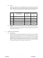
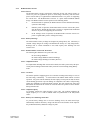
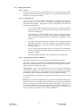
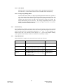
Liebert PowerSure PSI UPS GUIDE SPECIFICATIONS 1000VA to 3000VA Single - Phase Uninterruptible Power Supply Systems 1.0 1.1 GENERAL SUMMARY This specification defines the electrical and mechanical characteristics and requirements for a continuousduty single-phase, solid-state, uninterruptible power system. The uninterruptible power system, hereafter referred to as the UPS, will provide high-quality AC power for sensitive electronic equipment loads. 1.2 STANDARDS The UPS is designed in accordance with the applicable sections of the current revision of the following documents. Where a conflict arises between these documents and statements made herein, the statements in this specification will govern. 120V Units UL 1778, c-UL listed (to CSA 22.2 No. 107.1) FCC Part 15, Class B for 1000VA & 1440VA FCC Part 15, Class A for 2200VA & 3000VA ANSI C62.41, Category A, Level 3 (IEEE 587, Category A); EN61000-4-5, Level 3, Criteria B EN61000-4-2, Level 3, Criteria B EN61000-4-3, Level 3, Criteria A EN61000-4-4, Level 4, Criteria A EN61000-4-6 EN61000-3-2 EN61000-3-3 ISTA Procedure 1A 230V Units EN62040-1-1, TUV/GS listed, CE compliance mark EN50091-2, Class B EN61000-4-2, Level 3, Criteria B EN61000-4-3, Level 3, Criteria A EN61000-4-6 EN61000-4-4, Level 4, Criteria A EN61000-4-5, Level 3, Criteria B EN61000-3-2 EN61000-3-3 ISTA Procedure 1 A PowerSure PSI 1000 – 3000VA 1 Guide Specification SL-23291 4/06 1.3. SYSTEM DESCRIPTION 1.3.1 Modes of Operation The UPS is designed to operate as a line-interactive system in the following modes: A. Normal - The critical AC load is continuously supplied with filtered power. The battery charger maintains a float-charge on the battery. B. Voltage Boost/Buck - During input power source abnormalities (sags and swells), the AC output power is corrected by means of boost (sag correction) or buck (swell correction) compensation taps. Operation of the compensation taps automatically maintains the proper output voltage for the connected critical equipment. The compensation taps is designed for indefinite operation to their limits. Operation of the compensation taps will not discharge the battery. C. Recharge - Upon restoration of utility / mains AC power, after a utility / mains AC power outage and complete or partial battery discharge, the unit automatically restarts and resumes supplying power to the critical AC load; and the battery charger recharges the battery. D. Battery - When the input power source exceeds the parameters defined in section 1.3.3.1, the critical AC load is supplied power by the inverter, which obtains its power from the battery. Typical detection and transfer time is 4-6 ms. E. Battery Start- The UPS is capable of starting without input power. The unit starts up and operates from the battery, with output frequency the same as the last operating frequency. 1.3.2 Design Requirements A. Voltage: Input/output voltage specifications of the UPS are: Input: 120V Units: 0-165 VAC, 60/50 Hz auto-sensing, single-phase, 2-wire-plus-ground. 230V Units: 0-325 VAC, 50/60 Hz auto-sensing, single-phase, 2-wire-plus-earth. Output: 120V Units: 110/120/127 VAC ±10%, 60/50 Hz, single-phase, 2-wire-plus-ground. (programmable) 230V Units: 220/230/240 VAC ±10%, 50/60 Hz, single-phase, 2-wire-plus-earth. (Programmable) B. Output Load Capacity: Maximum specified output load capacity of the UPS, regardless of load power factor, is: 1000VA / 750W 1440VA / 1080W 2200VA / 1650W 3000VA / 2250W 1920VA / 1500W (120V only) C. Internal Battery: The battery consists of valve regulated, non-spillable, maintenance-free, sealed, lead-acid cells. The battery is user replaceable and hot swappable. D. Battery Reserve Time: 5 minutes typical at full load with ambient temperature 77F (25C). E. Battery Recharge: The UPS contains a battery recharge rate designed to prolong battery life. Recharge time is 4 hours typical to 90% capacity after a complete discharge into full resistive load. PowerSure PSI 1000 – 3000VA 2 Guide Specification SL-23291 4/06 1.3.3 Performance Requirements 1.3.3.1 AC Input to UPS A. Voltage Configuration: The UPS operates at these values without drawing power from the batteries. 110 VAC nominal: single phase, 2-wire-plus-ground: 78 ─ 138 VAC (±3VAC), Buck compensation: 122VAC (±3VAC) Boost1 compensation: 98VAC (±3VAC) Boost2 compensation: 87VAC (±3VAC) 120 VAC nominal: single phase, 2-wire-plus-ground: 85 ─ 145 VAC (±3VAC), Buck compensation: 133VAC (±3VAC) Boost1 compensation: 107VAC (±3VAC) Boost2 compensation: 95VAC (±3VAC) 127 VAC nominal: single phase, 2-wire-plus-ground: 90 ─ 150 VAC (±3VAC), Buck compensation: 141VAC (±3VAC) Boost1 compensation: 113VAC (±3VAC) Boost2 compensation: 100VAC (±3VAC) 220 VAC nominal: single phase, 2-wire-plus-earth: 158 ─ 260 VAC (±6VAC) Buck compensation: 242 VAC (±6VAC) Boost1 compensation: 198 VAC (±6VAC) Boost2 compensation: 176 VAC (±6VAC) 230 VAC nominal: single phase, 2-wire-plus-earth: 166 ─ 272 VAC (±6VAC) Buck compensation: 248 VAC (±6VAC) Boost1 compensation: 207 VAC (±6VAC) Boost2 compensation: 184 VAC (±6VAC) 240 VAC nominal: single phase, 2-wire-plus-earth: 172 ─ 283 VAC (±6VAC) Buck Compensation: 264 VAC (±6VAC) Boost1 compensation: 216 VAC (±6VAC) Boost2 compensation: 192 VAC (±6VAC) B. Frequency: The UPS automatically senses the input frequency and operates within the following frequency specifications without drawing power from the batteries. 50 Hz Applications: 60 Hz Applications: 45 ─ 55 Hz (±0.1 Hz) 55 ─ 65 Hz (±0.1 Hz) C. Surge Protection: The 120 VAC units can withstand input surges of up to 570J without damage per criteria listed in IEEE C62.41, Category A, Level 3. The 230 VAC units can withstand input surges of up to 660J without damage per criteria listed in EN61000-4-5, Level 3, Criteria B. D. Input Connections: The 120 VAC units have an attached input cord 10 feet (3 meters) in length, measured between the inside edges of the connectors. The attached input cord has a NEMA 5-15P for the 1000 & 1440 VA models, a NEMA 5-20P for the 1920VA model, and a NEMA L5-30P on 2200 and 3000VA models. The 1000VA & 1440VA, 230 VAC units have IEC-320-C14 connectors while the 2200VA & 3000VA units have IEC-320-C20 connectors. The PS2200/3000RT2-230 units ship with (1) “Shucko” CEE 7/7 to IEC-320-C19 input cord. The PS2200/3000RT2-230E units ship with (1) “Shucko” CEE 7/7 to IEC-320-C19 & (1) UK BS1363 to IEC-320-C19 input cord. PowerSure PSI 1000 – 3000VA 3 Guide Specification SL-23291 4/06 1.3.3.2 AC Output A. Voltage Configuration: 120 VAC units: 110/120/127 VAC, 60/50 Hz, single-phase, 2-wire-plus-ground. 110/120/127 VAC, ±5% RMS prior to low battery warning; ±8% RMS after low battery warning (Battery mode) 230 VAC units: 220/230/240 VAC, 50/60 Hz, single phase, 2-wire-plus-earth. 220/230/240 VAC, ±5% RMS prior to low battery warning; ±8% RMS after low battery warning (Battery mode) B. Voltage Regulation: ±10% steady state. C. Frequency Regulation: +0.1Hz synchronized to utility / mains. +0.5Hz free running or on battery operation. D. Load Power Factor Range: 0.6 lagging to 1.0 (unity). E. Inverter Overload Capability: Overload Warning (visual and audible alarms) occurs between 100%─109% of rated capacity, continuous duty. Shutdown occurs at the following levels: >110 ─ 165%; after 300 seconds (Normal mode) >165 ─ 200%; after 60 seconds (Normal mode) >200% - short-circuit; after 15 cycles (Normal mode) >100 – 110%; after end of discharge (Battery mode) >110%; after 30 seconds (Battery mode) >120%; after 5 cycles (Battery mode) >150%; after 1cycle (Battery mode) F. Voltage Transient Response: ±15% in Normal mode for 0-100-0% loading of the UPS rating, ±5% in Battery mode for 20-100-20% loading of the UPS rating. G. Transient Recovery Time: To within ±8% of nominal voltage in < 2 cycles. H. Efficiency: >95% (Normal mode) >90% (Buck/Boost mode) >70% (Battery mode) I. Output Power Cords: The 230 VAC units have two (2) detachable IEC-320-C14 output power cords measuring 2m (6.6 ft) in length. PowerSure PSI 1000 – 3000VA 4 Guide Specification SL-23291 4/06 1.4 ENVIRONMENTAL CONDITIONS A. Ambient Temperature Operating: 32oF ─ 104oF (0oC ─ 40oC) for altitudes 0 ─ 5,000 ft. (0 ─ 1500 meters) above sea level 32°F ─ 95°F (0°C ─ 35°C) for altitudes 5000 ft ─ 10,000 ft (1500 ─ 3000 meters) above sea level. 77o F (25oC) for optimum battery performance Storage: 5°F ─ 104°F (-15°C ─ 40°C) with batteries 5oF ─ 122oF (-15oC ─ 50oC) without batteries 68oF (20oC) for optimum battery storage. B. Relative Humidity 0 ─ 95% non-condensing. C. Altitude: 1000VA & 1440VA: 2,000 m (6,500 ft. max.), without power derating when operated within the temperature specified in section 1.4.A. 1920VA, 2200VA, & 3000VA: 3,000 m (10,000 ft. max.), without power derating when operated within the temperature specified in section 1.4.A. D. Audible Noise Noise generated by the UPS during normal operation does not exceed the following values when measured at 1 meter from the surface of the UPS, “A” weighted: Model Audible Noise PS1000RT2-120/230 & PS1440RT2-120/230 <40 dBA, internal fan(s) Off <50 dBA, internal fan(s) On PS1920RT2-120/230, PS2200RT2-120/230 & PS3000RT2-120/230 <40 dBA, internal fan(s) Off <60 dBA, internal fan(s) On E. Electrostatic Discharge The 120 VAC units are able to withstand an electrostatic discharge compliant to EN61000-4-2, level 3, Criteria B without damage and without affecting the connected load. The 230 VAC units are able to withstand an electrostatic discharge compliant to EN61000-4-2, level 3, Criteria B without damage and without affecting the connected load. PowerSure PSI 1000 – 3000VA 5 Guide Specification SL-23291 4/06 1.5 USER ACCESSORIES AND PACKAGING The specified UPS system is supplied with one (1) user's manual. The manual includes installation drawings and instructions, a functional description of the equipment, safety precautions, illustrations, operating procedures, and general maintenance guidelines. The UPS is also supplied with one (1) Multilink software CD, one (1) Multilink serial cable (10-ft; 3m), one (1) USB cable (6-ft; 1.8m), one (1) RJ-11 cord (7-ft; 2.1m), one (1) pair of support base, one (1) Front bezel, one (1) Vertical display overlay, one (1) pair of Rack mount handles, one (1) pair of Fixed rails. The package of the 230 VAC units also includes two (2) output power cords (2m; 6.6 ft). The package meets the requirements of ISTA Procedure 1A. 1.6 WARRANTY The manufacturer warrants the UPS against defects in materials and workmanship for two (2) years. The warranty covers all parts. An optional one (1) or three (3) year extended warranty is available from the manufacturer. 1.7 QUALITY ASSURANCE 1.7.1 Manufacturer Qualifications Liebert Corporation provides more than twenty years experience in the design, manufacturing, and testing of solid-state UPS systems and the company is certified to ISO 9001:2000. 1.7.2 Factory Testing Before shipment, the product is tested to assure compliance with the specification. 2.0 2.1 PRODUCT FABRICATION All materials and components making up the UPS are new, of current manufacture, and have not been in prior service except as required during factory testing. All relays are provided with dust covers. 2.1.2 Wiring Wiring practices, materials, and coding are in accordance with the requirements of the standards listed in section 1.2. All wiring is copper. PowerSure PSI 1000 – 3000VA 6 Guide Specification SL-23291 4/06 2.1.3 Cabinet The UPS unit comprised of: TVSS & EMI/RFI Filters, Relay, Automatic Voltage Regulator, Battery Charger, Battery consisting of the appropriate number of sealed battery cells, Inverter (1000 & 1440 models only), DC-to-DC Converter (2200&3000 models only) and Bi-Directional Converter; is housed in a rack-tower NEMA type 1 enclosure. Dimensions and weights are: UNIT UNIT DIMENSIONS W x D x H in (mm) 2.1.4 120 VAC UNITS WEIGHT 230 VAC UNITS WEIGHT lbs (kg) kg (lbs) 1000VA 3.43 x 22 x 17 (87 x 557 x 430) 61.7 (28) 28 (61.7) 1440VA 3.43 x 22 x 17 (87 x 557 x 430) 68.2 (31) 31 (68.2) 1920VA 3.43 x 24.1 x 17 (87 x 612 x 430) 77 (35) 35 (77) 2200VA 3.43 x 24.1 x 17 (87 x 612 x 430) 77 (35) 35 (77) 3000VA 3.43 x 24.1 x 17 (87 x 612 x 430) 81.6 (37) 37 (81.6) Cooling The UPS is forced air cooled by variable speed internal fan(s), which operate only when needed to maintain internal temperatures to acceptable levels. Air intake is through the front of the unit and exhausted out the rear of the unit. 2.2 COMPONENTS AND OPERATION 2.2.1 Input Protection The UPS has built-in protection against undervoltage, overcurrent, and overvoltage conditions including low-energy lightning surges introduced on the primary input power source. The UPS is provided with an input circuit protector. The 120 VAC UPS models withstand input surges without damage per criteria listed in IEEE C62.41, Category A, Level 3. The 230 VAC UPS models withstand input surges without damage per criteria listed in EN61000-4-5, Level 3, Criteria B. Additionally, the UPS is supplied with one pair of Data Line Protection Connectors to provide phone, fax or modem line surge protection via RJ-45 connectors. These Data Line Protection Connectors provide transmission for 10/100 Base-T Ethernet connection. PowerSure PSI 1000 – 3000VA 7 Guide Specification SL-23291 4/06 2.2.2 Bi-Directional Converter 2.2.2.1 General The Bi-Directional Converter incorporates solid-state devices and control circuitry to convert AC power to regulated DC power to “float charge” the battery; and convert DC power from the battery to regulated and conditioned sinewave AC power for supporting the critical load. The Bi-Directional Converter is a pulse width modulated (PWM) design. The Bi-Directional Converter operates in the following modes: 1. In Normal mode of operation, the Bi-Directional Converter maintains the battery system at a float charge. 2. In Battery mode of operation, the Bi-Directional Converter converts DC power from the battery, through the DC-to-DC Converter, to regulated and conditioned sinewave AC power for supporting the critical load. 3. In the recharge mode of operation, the Bi-Directional Converter converts AC power to regulated DC power to recharge the battery. 2.2.2.2 Battery Recharge The UPS contains a battery recharge rate designed to prolong battery life. The battery is constant voltage charged to recharge and maintain the battery in a fully charged state. Recharge time is 4 hours maximum to 90% rated capacity after discharge into full resistive load. 2.2.2.3 Bi-Directional Converter DC Protection The following DC shutdown levels protect the UPS: DC Overvoltage Shutdown DC Undervoltage Shutdown (End of Discharge) DC Undervoltage Warning (Low Battery Reserve) 2.2.2.4 Output Protection For output faults including short circuits and overloads, the UPS is protected by the input circuit protector during Normal mode and by electronic current limiting during Battery mode. 2.2.2.5 Overload The UPS is capable of supplying power for overloads exceeding 100% and up to 110% of full load rating, continuously. A visual indicator and audible alarm indicate overload operation. For greater current demands, the UPS employs circuit protector and electronic current-limiting protection to prevent damage to components. The UPS is self-protecting against any magnitude of connected output overload. The UPS control logic senses and disconnects the UPS from the critical AC load and clears the protective circuit breaker during Normal mode. 2.2.2.6 Output Frequency An oscillator controls the output frequency of the UPS. The oscillator maintains the output frequency to ± 0.1 Hz of nominal when not synchronized to the utility/mains source. 2.2.2.7 Battery Over-Discharge Protection To prevent battery damage due to excessive discharge levels, the UPS control logic automatically monitors the battery voltage and load level and switches off the output at the predetermined battery shutdown voltage set point. PowerSure PSI 1000 – 3000VA 8 Guide Specification SL-23291 4/06 2.2.3 Display and Controls 2.2.3.1 General The UPS is provided with a microprocessor-based unit status and control display designed for convenient and reliable user operation. The status and alarm indicators are displayed on a status indicator display. 2.2.3.2 System Indicators There is a row of Load Level indicators that display the approximate electrical load placed upon the UPS. There is also a row of Battery Level indicators that display the approximate battery capacity. Finally, there are five (5) status indicators on the front of the UPS as described below: The “AC Input” indicator illuminates when utility power is available and within the input specifications. For the 120V units, this indicator flashes when the UPS detects a Site Wiring Fault. The “Buck/Boost” indicator illuminates when the UPS is operating in Boost mode to compensate for a low utility voltage condition. This indicator flashes when the UPS is operating in Buck mode to compensate for a high utility voltage condition. The “Battery” indicator illuminates green when the UPS is operating on battery and flashes green when a low battery condition occurs. The Battery Indicator illuminates amber when a bad battery is detected, indicating that the batteries need to be replaced. The “Over Temp” indicator flashes when the UPS detects an over temperature condition. This indicator illuminates when the UPS shuts down due to an over temperature condition. The “Fault” indicator illuminates when the UPS detects an internal problem. 2.2.3.3 ON/Alarm Silence/Battery Test Button This button controls output power to connected load(s) and has three functions: ON - When the UPS is Off, pressing the ON/Alarm Silence/Battery Test button for more than one (1) second will start the UPS, and an audible alarm sounds briefly. The UPS is capable of starting on battery (battery start). Alarm Silence - When a UPS audible alarm is active, pressing and releasing the ON/Alarm Silence/Battery Test button will silence the active audible alarm, whether utility power is present or not. Once the alarm silence function has been activated, all active audible alarms will remain silenced until a new alarm condition is detected. The LOW BATTERY, OVER TEMP and OVERLOAD warning audible alarms CANNOT be silenced. Battery Test - To initiate a manual battery test, press the ON/Alarm Silence/Battery Test button for at least one second while operating from utility power with no alarm conditions present. The UPS is also provided with an automatic biweekly battery test feature. The test ensures the capability of the battery to supply power to the inverter while loaded. If the battery fails the test, the UPS will display a warning to indicate the batteries need replaced. The battery test feature is user accessible via Multilink. PowerSure PSI 1000 – 3000VA 9 Guide Specification SL-23291 4/06 2.2.3.4 OFF Button When the UPS is on (in either Normal or Battery mode), pressing the OFF button for more than one (1) second will shut down the UPS. An audible alarm sounds briefly. 2.2.3.5 Voltage Programming Button The PowerSure PSI contains a Voltage Programming button that allows the operator to select the nominal utility voltage. This setting changes the utility transfer points (low and high) of the UPS and the nominal output voltage when operating in Battery mode. The operator can select between 110 (220), 120 (230) and 127 (240) VAC output. The factory-default setting is 120 (230) VAC. The Voltage Programming button is a push button type and is behind the plastic bezel on the front panel of the UPS. To access the button, the front bezel must be removed. 2.2.4 Internal Battery Valve regulated, non-spillable, lead-acid cells are used as a stored-energy source for the specified UPS system. The battery is housed internal to the UPS cabinet, and sized to support the inverter at rated load and power factor, with ambient temperature of 77 o F (25 o C) for a minimum of 5 minutes reserve time. The expected life of the battery is 3 - 5 years or 250 complete discharge cycles. Optional external battery cabinets are available to extend battery run times. 2.2.5 Output Distribution Output distribution is integral to the UPS and is located on the rear of the unit. UNIT 230 VAC UNITS 1000VA & 1440 VA (8) NEMA 5-15R; (8) IEC-320-C13 1920VA (6) NEMA 5-15R (2) NEMA 5-20R T-Slot, accepts 15A plug (6) NEMA 5-15R (2) NEMA 5-20R T-Slot, accepts 15A plug (4) NEMA 5-15R (2) NEMA 5-20R T-Slot, accepts 15A plug (1) NEMA L5-30R Not Available 2200VA 3000VA PowerSure PSI 1000 – 3000VA 120 VAC UNITS 10 (8) IEC-320-C13 (1) IEC-320-C19 (8) IEC-320-C13 (1) IEC-320-C19 Guide Specification SL-23291 4/06 2.2.6 Communications The UPS has a DB-9 (9 pin female) connector on the rear to allow UPS status communications with a computer system running MultiLink™ software. The DB-9 is capable of supplying serial communication, on battery and low battery signals. MultiLink, Liebert’s UPS monitoring and shutdown software, is shipped with the UPS, along with a 10-ft. (3m) DB-9 cable required for running MultiLink. The UPS can signal “on battery” and “low battery” using opto-couplers. When the UPS is operating in Battery mode, it can receive a signal from the host computer system that will shut down the UPS (after gracefully shutting down the operating system on the host computer system) when the remaining battery run time is low. The timing of the signal depends on MultiLink’s configuration settings. This shutdown signal (5-12VDC) must have a duration of at least 1.5 seconds for the UPS to be shut down. The UPS communicates via serial communications using Liebert ESP II protocol. The pin out configuration of the DB9 connector is: Pin 1 2 3 4 5 6 7 8 9 Assignment Description Low Battery (open collector) UPS TxD (typical RS-232 levels) UPS RxD (typical RS-232 levels) Battery Mode Shutdown (5-12V) Common Any Mode Shutdown (short to pin 5) Low Battery (open emitter) AC Fail (open emitter) AC Fail (open collector) 2.2.6.1 Any Mode Shutdown - Via Pins 5 & 6 When Pin 6 is shorted to Pin 5, the UPS output is shut Off regardless of what mode the UPS is operating in. The UPS cannot be started as long as the pins are shorted. When the short is removed, the UPS output can be enabled by pressing the ON/Alarm Silence/Battery Test button. 2.2.6.2 Battery Mode Shutdown—Via Pins 4 & 5 While the UPS is operating on battery (with no battery test in progress), a 5-12VDC signal for 2 seconds or longer is required to signal a shutdown. Signals for less than 2 seconds are ignored. After Pin 4 receives the shutdown signal, a 2-minute shutdown timer inside the UPS begins a countdown. The timer cannot be stopped. If utility power returns during the 2-minute timer countdown, the shutdown timer continues until the end of 2 minutes and then the UPS turns Off. By default, autorestart is enabled so the UPS will restart after 10 seconds. If autorestart is disabled via MultiLink software, the UPS remains Off until a manual restart. 2.2.6.3 USB Interface Port The PowerSure PSI has a USB interface port for communication that will work with the built-in Microsoft Power Manager software on the user’s PC, if the PC is so equipped. It will provide UPS status and manages the automatic orderly shutdown of the computer. The UPS (USB) communications meets HID standard, version 1.11. All USB models are compatible with Microsoft Windows 2000, Windows XP and Mac OS 10.2 or later. All USB models ship with a 6-ft. (1.8m) USB cable. PowerSure PSI 1000 – 3000VA 11 Guide Specification SL-23291 4/06 2.2.6.4 Data Line Protection Connectors Data line (in and out) connectors are on the rear of the UPS and provide transient voltage surge suppression (TVSS) for Phone/Fax/DSL/Internet/Modem devices. 2.2.6.5 UPS Intelligent Communications The PowerSure PSI is equipped with an Intellislot® port to provide advanced communication and monitoring options. Liebert’s MultiLink software continually monitors the UPS and can shut down your computer or server in the event of an extended power failure. MultiLink can also be configured for use without the serial cable when the Intellislot OCWEBCARD is installed in the UPS. Additionally, MultiLink can be configured to coordinate shutdown across the network with other computers running MultiLink when you purchase a MultiLink License Kit. Several option cards are available for use in the Intellislot port of the PowerSure PSI. The Intellislot OCWEBCARD provides SNMP and Web-based monitoring and control of the UPS across the network. The Intellislot MultiPort 4 Card allows you to install MultiLink software on four computers and coordinate shutdown in the event of a power failure. The RELAYCARD-INT provides dry contact relay outputs for custom-wired applications and delivers support for built-in shutdown for AS/400 systems. The USB, Intellislot and Contact Closure communications operate in parallel. Using the OCWEBCARD disables the Serial Communications of the DB-9. PowerSure PSI 1000 – 3000VA 12 Guide Specification SL-23291 4/06