1
-
Océ
VarioPrint® 6000
Ultra Line
Experience ultra speed
o
User manual
Operating
information
Copyright
© 2006-2011, Océ
All rights reserved. No part of this work may be reproduced, copied, adapted, or transmitted
in any form or by any means without written permission from Océ.
Océ makes no representation or warranties with respect to the contents hereof and specifically disclaims any implied warranties of merchantability or fitness for any particular purpose.
Furthermore, Océ reserves the right to revise this publication and to make changes from
time to time in the content hereof without obligation to notify any person of such revision
or changes.
Edition: 07-2011
Contents
Contents
Chapter 1
Preface.................................................................................................................7
Trademarks.................................................................................................8
Notes for the reader...................................................................................9
... and Training?........................................................................................11
Online support for your product.............................................................12
Chapter 2
Introduction.......................................................................................................15
Introduction to the Océ VarioPrint® 6000 Ultra Line.............................16
Available documentation.........................................................................17
Chapter 3
Power information............................................................................................19
The power modes....................................................................................20
Turn on the machine................................................................................23
Shut down the machine...........................................................................24
Chapter 4
Overview of the system components.............................................................25
Introduction to the main system components.......................................26
The operator panel...................................................................................28
The operator attention light....................................................................31
The output locations................................................................................33
The paper modules..................................................................................36
Chapter 5
Working with the operator panel....................................................................39
Introduction...............................................................................................40
The dashboard....................................................................................40
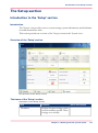
The Schedule view...................................................................................43
Introduction to the 'Schedule' view..................................................43
Load the media...................................................................................47
Load media via the 'Schedule' view.................................................49
Instructions for printing to the stacker/stapler (iMFS).....................51
Stop a job............................................................................................52
The Jobs view...........................................................................................55
Introduction to the 'Jobs' view..........................................................55
Schedule a waiting job for printing..................................................63
Reprint a job........................................................................................64
Give priority to a print job.................................................................65
3
Contents
Print an urgent job immediately.......................................................66
Delete print jobs.................................................................................67
Print a scheduled job later.................................................................69
Make a proof.......................................................................................70
Print a job ticket..................................................................................71
Bundle jobs in the list of 'Waiting jobs' ...........................................72
Select more than one job for printing..............................................74
Checking and changing the job properties......................................76
Contradiction handling.................................................................76
Change the number of sets..........................................................77
Check the first set.........................................................................78
Change the page range you want to print..................................80
Enable the separator sheets........................................................81
Rename a job................................................................................82
Change the stacking method per job..........................................83
Change '2-sided' into '1-sided' and vice versa...........................84
Shift the image in the document printing mode........................85
Change the print delivery settings..............................................87
Change the number of staples....................................................90
Punch or fold the output..............................................................91
Select a different media for a job................................................94
Enable or disable the use of trailer pages..................................95
The Trays view.........................................................................................96
Introduction to the 'Trays' view........................................................96
Assign the media to a paper tray......................................................99
Use hotfolders........................................................................................101
Introduction to hotfolders................................................................101
Activate the hotfolder function........................................................102
Create a hotfolder.............................................................................103
Create a shared network folder on a workstation..........................104
Create a hotfolder default ticket ('default_ticket.jdf').....................106
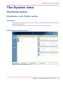
The System view....................................................................................107
The Printer section...........................................................................107
Introduction to the 'Printer' section..........................................107
Check the status of the toner reservoirs...................................109
Check the status of the staple cartridges..................................111
Check the status of the puncher waste box..............................113
The Maintenance section.................................................................114
Introduction to the 'Maintenance' section................................114
Reset the day counters...............................................................116
Find the meter readings.............................................................118
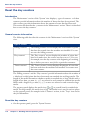
The Setup section.............................................................................119
Introduction to the 'Setup' section............................................119
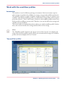
Work with the workflow profiles...............................................121
4
Contents
Change the language.................................................................126
Change the warning time...........................................................128
Truncate the job name...............................................................129
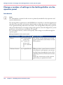
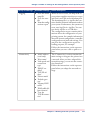
Change the advanced media settings.......................................130
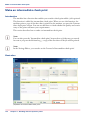
Make an intermediate check print.............................................134
Change a number of settings in the Settings Editor via the operator panel....................................................................................136
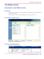
The Media section............................................................................139
Introduction to the 'Media' section...........................................139
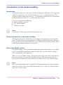
Introduction to the media handling..........................................141
Add temporary media to the 'Media catalog' .........................143
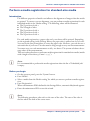
Perform a media registration for standard-size media...........145
Perform a media registration for large media..........................152
The Transaction section (optional).................................................159
Introduction to the 'Transaction' section .................................159
Error handling and output recovery..........................................163
Activate the transaction printing function................................168
Shift the image in the transaction printing mode....................170
Handle the media messages......................................................172
Create a transaction setup.........................................................175
Chapter 6
Optional finishers and other devices............................................................179
®
iXDP (integrated eXchangeable Die Punch) - VarioPrint 6160 only..180
Introduction.......................................................................................180
Introduction.................................................................................180
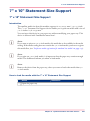
Operating information.....................................................................182
Main parts...................................................................................182
Die sets available........................................................................185
Empty the chip tray....................................................................187
Replace a die set.........................................................................189
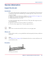
Service information..........................................................................191
Inspect the die sets.....................................................................191
Lubricate the die sets.................................................................193
Troubleshooting.........................................................................195
Specifications..............................................................................199
iP&F (integrated Puncher & Folder) .....................................................200
Introduction.......................................................................................200
Introduction.................................................................................200
Operating information.....................................................................212
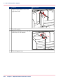
Main parts...................................................................................201
Output locations.........................................................................203
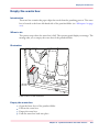
Empty the waste box..................................................................205
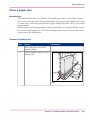
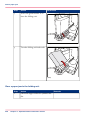
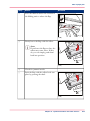
Clear a paper jam........................................................................207
5
Contents
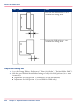
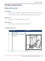
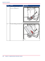
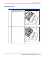
Puncher replacement.......................................................................221
Replace the puncher...................................................................221
Specifications..............................................................................227
Form Assist Module...............................................................................229
Form Assist Module.........................................................................229
EasyLift....................................................................................................231
EasyLift..............................................................................................231
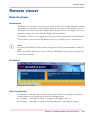
Remote viewer........................................................................................233
Remote viewer..................................................................................233
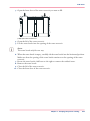
7" x 10" Statement Size Support...........................................................235
7" x 10" Statement Size Support.....................................................235
Chapter 7
Keeping the printer running..........................................................................237
Add toner................................................................................................238
Finisher: Add staples..............................................................................240
Stacker/stapler (iMFS): Replace the staple cartridge...........................246
Troubleshooting.....................................................................................247
Appendix A
Miscellaneous..................................................................................................251
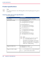
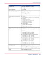
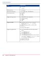
Product specifications............................................................................252
6
Chapter 1
Preface
Trademarks
Trademarks
List of trademarks
Océ, VarioPrint, PRISMAaccess, PRISMAprepare, PRISMAproduction and DPlink are
registered trademarks of Océ-Technologies B.V.
Xerox, DocuTech, DigiPath and FreeFlow are registered trademarks of Xerox Corporation.
Adobe and PostScript are registered trademarks of Adobe Systems Incorporated.
Products in this publication are referred to by their general trade names. In most, if not
all cases, these designations are claimed as trademarks or registered trademarks of their
respective companies.
8
Chapter 1 - Preface
Notes for the reader
Notes for the reader
Introduction
This manual helps you to use the Océ VarioPrint® 6000 Ultra Line. The manual contains
a description of the product and guidelines to use and operate the Océ VarioPrint® 6000
Ultra Line.
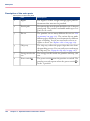
Definition
Attention-Getters
Parts of this manual require your special attention. These parts can provide the following:
• Additional general information, for example, information that is useful when you
perform a task.
• Information to prevent personal injuries or property damage.
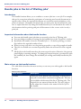
Warning, Caution and Note
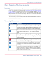
The words Warning, Caution and Note draw your attention to important information.
Overview of the attention-getters#
Word
Icon
Indicates
Warning
Ignoring this warning could cause serious injury or
even death.
The Warning indication has several icons that warn
against various hazards. The icons are shown below.
Warning
General hazard
Warning
Hot surface
Warning
Electric shock
Warning
Moving parts
Warning
Laser beam
Chapter 1 - Preface
9
Notes for the reader
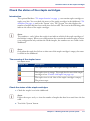
Word
Icon
Indicates
Caution
Ignoring this warning could cause injury or damage to
property.
Note
Indicates additional important information.
The use of heat-resistant gloves is mandatory when you
carry out these actions.
Safety information
Before using this Océ product, make sure that you read and understand the safety information which is part of the user documentation. You can download the safety information
via http://global.oce.com/support/ or, if applicable, find it on the user documentation
CD/DVD that is delivered together with the machine or obtain the safety information
from your local Océ representative. To avoid potential hazards, maintenance is strictly
preserved to properly qualified and trained service technicians.
10
Chapter 1 - Preface
... and Training?
... and Training?
Océ Education services
Knowledge is power. Especially when it comes to document workflow. Océ Education
services systematically transfer our expert knowledge to your employees.
Our proven training methods give you insight that allows you to maximize results from
all your Océ hardware and software.
And they lead to improved cost control, productivity and quality, as well as faster return
on your investment.
For more information about Océ Education Services
download the Océ Education services brochure at http://global.oce.com/services/professional-services/education-services
Chapter 1 - Preface
11
Online support for your product
Online support for your product
Introduction
Océ offers comprehensive support for your product on the website:
http://global.oce.com/
Here you can find the latest information that can help you to take full benefit of your
product. You can also find answers to your questions.
Please visit the website regularly for updates on the following topics:
• Downloads:
• Support
• Supplies
Downloads:
User manuals, printer drivers and other resources can change without prior notice. To
stay up-to-date, you are advised to download the latest resources from:
http://global.oce.com/support
Before using your product, you must always download the latest safety information for
your product. Before using your product, make sure that you read and understand all
safety information in the manual entitled "Safety Instructions".
Support
A Knowledge Base (OKB) with answers to your questions or problems is continuously
being updated. To find an answer to your question or problem, please visit:
http://global.oce.com/support and select your product.
In the Support section, use the search field to enter your question. You will get a list of
possible answers.
Supplies
A media guide with the latest information is available on the website:
http://global.oce.com/supplies/
Here you can find the media that your product supports, for example. You can also find
more information about supplies for your product, such as toner. You can also order new
supplies directly through the website.
12
Chapter 1 - Preface
Online support for your product
Addresses of local Océ organizations
For the addresses of local Océ organizations, visit:
http://global.oce.com/contact/countries
Comments
Send your comments by e-mail to:
[email protected]
Chapter 1 - Preface
13
Online support for your product
14
Chapter 1 - Preface
Chapter 2
Introduction
Introduction to the Océ VarioPrint® 6000 Ultra Line
Introduction to the Océ VarioPrint® 6000 Ultra Line
Introduction
The Océ VarioPrint® 6000 Ultra Line is a series of high-volume, cut-sheet printers. The
machines are intended for both document printing and stream printing.
The key feature of the machine is the Océ Gemini Instant Duplex Technology. This
technology enables the machine to print the front side and back side of a sheet at the
same time. Depending on your version, the sustained print speed, including reconditioning, ranges from 170, 200, 250 to 314 images per minute (A4 / Letter) when you print
a 2-sided document.
The print speed for 1-sided documents (A4/Letter) ranges from 125 images per minute
to 157 images per minute (Océ VarioPrint® 6320 only).
This section gives a short description of the main features of the machine.
Note:
Not all the configurations mentioned in this user manual are available worldwide. Please
contact your local dealer for the available configurations in your country.
Overview of the main features
• Océ Gemini Instant Duplex Technology that enables the printing on both sides of a
sheet at the same time.
• Advanced scheduling concept on the operator panel to keep the machine running.
• Load and assign the media while the machine prints.
• Support of up to 12 paper trays (total input capacity up to 13,800 sheets) and a roll
feeder.
Support of up to 3 stackers, a finisher, a stacker/stapler and other external finishers.
Support of a large range of media, media sizes and media weights.
Support of PS/PCL/PDF and streaming PS.
Support of a large range of software products, for example the Océ PRISMA series,
Xerox® DigiPath® and Xerox® FreeFlow® Makeready, Kodak® KDK Link.
• Support of RDO files via Océ DP Link.
• Support of a direct copy path from the optional Océ DS60 scanner to the printer.
•
•
•
•
16
Chapter 2 - Introduction
Available documentation
Available documentation
Introduction
This machine is delivered with the following items:
• A 'Documentation and Driver Notice'
• A 'Safety Information Sheet'.
Note:
Please check www.oce.com for the latest version of the documentation.
Main Content of the User Manuals
The following table provides an overview of the main content of the user manuals.
Main Content of the User Manuals#
User Manual
Main content
Operating information
•
•
•
•
•
Maintenance tasks
• Replacing parts
• Cleaning parts
• Solve a paper jam in the engine module
Safety information
• Instructions for safe use
Overview of the main system components
Working with the operator panel
Handling and managing jobs on the operator panel
Optional finishers and other devices
Add media, toner and staples
Chapter 2 - Introduction
17
Available documentation
18
Chapter 2 - Introduction
Chapter 3
Power information
The power modes
The power modes
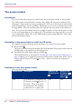
Introduction
This section describes the power switches and the main power modes of the machine.
The table in this section describes, among other things, the low-power mode and the
sleep mode. These modes are energy-saving modes. You can set the timers for these modes
in the Settings Editor on the controller. Furthermore, you can set a calendar timer in the
Settings Editor. Then the machine will wake up from the sleep mode at the indicated
time. You can use the calendar timer for example to make sure that the machine is ready
for use at the beginning of your working day. The machine can warm up before you start
your working day. Please refer to the online help on the Settings Editor for more information about these timers.
Description of the power switch and the On/Off button
The machine has the following switch and button to control the power supply.
• Power switch
The power switch is located at the back side of the machine. The power switch connects
and disconnects the machine to the mains power.
• On/Off button with amber and green LEDs .
The On/Off button on the machine ‘Introduction to the main system components’ on
page 26 allows you to toggle between the stand-by mode and the sleep mode. This is
only possible if the power switch is in the '1' position and the start-up phase is
completed.
Description of the main power modes
The main power modes#
20
Power mode
Description
Status of the
On/Off button
Status of the
Hold button
and Release
button
Off
The machine is completely off.
The power switch is in the 'O'
position. There is no power
consumption. The machine
cannot receive or print jobs.
Off
Off
Chapter 3 - Power information
The power modes
Power mode
Description
Status of the
On/Off button
Status of the
Hold button
and Release
button
Starting up
(divided into 2
stages)
Stage 1: After you put the power
switch in the 'I' position, but
before you press the On/Off
button .
Blinking amber
Off
Stage 2: After you press the
On/Off button .
Continuous
green
On
Stand-by
mode
The machine is ready to print
jobs.
Continuous
green
On
Run mode
The machine is busy.
Continuous
green
On
Low-power
mode
The machine automatically enters the low-power mode when
the machine has been in the
stand-by mode for a defined
time and no button was touched.
The machine wakes up when a
job arrives in the list of 'Scheduled jobs' or when you touch a
button. The machine will start
to warm up.
Continuous
green
On
Going into
sleep mode
The machine is preparing to go
into sleep mode.
Blinking amber
On
Chapter 3 - Power information
21
The power modes
22
Power mode
Description
Status of the
On/Off button
Status of the
Hold button
and Release
button
Sleep mode
The machine automatically goes
from the low-power mode into
the sleep mode after a defined
time.
You can also place the machine
into the sleep mode manually.
Press the On/Off button to do
this. The machine will enter the
sleep mode as soon as the list of
'Scheduled jobs' is empty.
The machine will wake up from
the sleep mode when you press
the On/Off button or when
the calendar timer expires. The
machine will also wake up when
a printable job arrives in the list
of 'Scheduled jobs', provided
that the function 'Automatic
wake-up' in the Settings Editor
is enabled.
Continuous
amber
Off
Chapter 3 - Power information
Turn on the machine
Turn on the machine
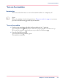
Introduction
This section describes how to turn on the machine when it is completely off.
Note:
When the machine is in the sleep mode (see ‘The power modes’ on page 20), you must
press the On/Off button to wake up the machine.
Turn on the machine
1. Put the power switch at the back of the machine in the 'I' position.
The On/Off button blinks amber while the machine and the controller start up.
Wait until the operator panel asks you to press the On/Off button .
2. Press the On/Off button .
The On/Off button remains green.
The machine warms up.
Chapter 3 - Power information
23
Shut down the machine
Shut down the machine
Introduction
This section describes how to shut down the machine completely, for example for the
holidays.
Note:
If you want to put the machine into the sleep mode manually (see ‘The power modes’ on
page 20), for example at the end of a working day, you must press the On/Off button
. Then the machine will go into the sleep mode as soon as the list of 'Scheduled jobs'
is empty. When the machine is in the sleep mode, the On/Off button is continuous
amber.
Shut down the machine
1. On the operator panel, press the 'System' button.
2. Touch the 'Setup' button.
3. Touch the 'Shut down system' button in the 'User interface' section.
A dialog box asks you to confirm that you really want to shut down the machine.
4. Press 'Yes'.
A message indicates when the shutdown will begin. Wait until the following has happened.
• The Hold button and the Release button are off
• The On/Off button blinks amber
• The screen of the operator panel is off.
5. Put the power switch
24
at the back of the machine in the 'O' position.
Chapter 3 - Power information
Chapter 4
Overview of the system
components
Introduction to the main system components
Introduction to the main system components
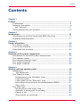
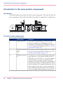
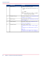
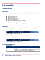
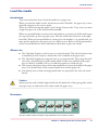
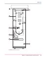
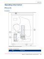
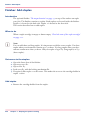
Introduction
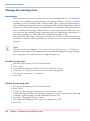
The following illustration shows the main system components. The table describes the
main components. Please follow the links in the table for comprehensive information.
2
8
1
1
2
3
4
3
5
6
7
9
4
[10] The main system components
The main system components
The main system components#
26
Component
Function
1
Operator panel
The operator panel helps you with your daily
work, for example the scheduling of the jobs.
Furthermore, the operator panel helps you to solve
errors or perform maintenance tasks (see ‘The operator panel’ on page 28).
2
Operator attention
light
The operator attention light enables you to check
the status of the system from a distance (see ‘The
operator attention light’ on page 31).
3
Roll feeder (optional)
A roll feeder is an optional device that adds paper
input capacity to your printer. When you use a
roll feeder, you can only use 1 or 2 paper modules.
A combination of 3 paper modules and a roll
feeder is not possible. The operator panel displays
the roll feeder and gives feedback about the status
of the roll feeder. For example whether the roll is
full or empty. Please refer to the documentation
of the roll feeder manufacturer for more information, for example about replacing an empty roll.
Chapter 4 - Overview of the system components
Introduction to the main system components
Component
Function
4
Paper module
The paper module contains 4 paper trays. The
paper trays contain the media that will be printed.
The default configuration of the system contains
1 paper module. You can add 1 or 2 more paper
modules to the default configuration to increase
the media input capacity (see ‘The paper modules’
on page 36).
5
Engine module
The engine module contains the components that
print the media. Access to the engine module is
only required when a paper jam occurs or when
maintenance is required. The doors at the left-hand
side and right-hand side of the engine module give
access to the toner units.
6
Puncher (optional)
The puncher (iXDP) can make holes in the prints.
The number of holes depends on the die set that
is installed (see ‘Replace a die set’ on page 189).
7
Stacker
The stacker is the output location of a default
configuration. The system supports up to 3 stackers (see ‘The output locations’ on page 33).
8
Finisher (optional)
The finisher on top of the stacker is an optional
output location for the print jobs. The finisher can
staple the jobs (see ‘The output locations’ on page
33).
9
Stacker/stapler (optional)
The stacker/stapler (iMFS) is an optional output
location for the print jobs (see ‘The output locations’
on page 33). The stacker/stapler supports a large
number of media sizes.
Chapter 4 - Overview of the system components
27
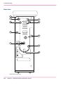
The operator panel
The operator panel
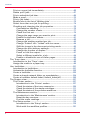
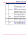
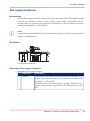
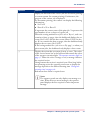
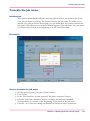
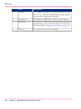
Introduction
The operator panel is a touch screen panel. You must touch the buttons on the operator
panel to access the various functions. The operator panel is divided into 4 main views.
The taskbar at the bottom of the screen contains the buttons that give access to the 4
main views. Furthermore, the operator panel has 2 hardkeys ( and ) at the bottom of
the panel.
This section gives an overview of the main keys and buttons of the operator panel.
Note:
You can clean the screen of the operator panel with a 50% mix of water and isopropyl
alcohol (K2). Use a lint-free cloth. Always put the cleaner onto the cloth and not directly
on the screen.
28
Chapter 4 - Overview of the system components
The operator panel
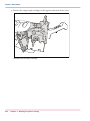
Illustration
3
4
5
1
6
2
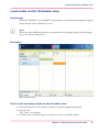
[11] The operator panel
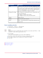
The main components of the operator panel
The main components of the operator panel#
1
Component
Function
Hold key
• Put the machine on hold
• Stop printing after a set
• Stop printing as soon as possible ‘Stop a
job’ on page 52.
Chapter 4 - Overview of the system components
29
The operator panel
2
Component
Function
Release key
• Allow the machine to print
• Resume printing when the machine is on
hold.
Note:
In the dashboard a softkey is available
with the same functionality.
30
3
'Schedule' button
Access the 'Schedule' view ‘Introduction to the
'Schedule' view’ on page 43.
4
'Jobs' button
Access the 'Jobs' view ‘Introduction to the 'Jobs'
view’ on page 55.
5
'Trays' button
Access the 'Trays' view ‘Introduction to the
'Trays' view’ on page 96.
6
'System' button
Access the 'System' view
‘Introduction to the 'Printer' section’ on page
107
‘Introduction to the 'Maintenance' section’ on
page 114
‘Introduction to the 'Setup' section’ on page 119
‘Introduction to the 'Media' section’ on page 139
Chapter 4 - Overview of the system components
The operator attention light
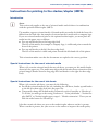
The operator attention light
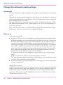
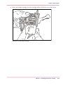
Introduction
The operator attention light informs you about the status of the machine. To improve
the productivity, the operator attention light can warn you some time before the machine
stops. You can set the warning time on the operator panel ‘Change the warning time’ on
page 128.
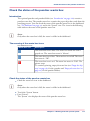
The operator attention light contains 3 lights (red, orange and green) that indicate the
current status of the machine. The colors of the lights match the status that is currently
indicated on the operator panel. For example, when operator interaction is required soon,
both the dashboard ‘The dashboard’ on page 40 and the operator attention light will
display an orange warning. The dashboard displays a message with the required action.
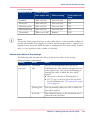
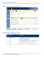
This section describes the meaning of the colors of the operator attention light.
[12] The operator attention light
Status colors
The colors of the operator attention light#
Color
Description
Red
The machine has stopped, for example because a required
media type is not available or an error has occurred.
Operator attention is required now.
Orange
The machine will stop soon, for example because an output
location is almost full. The orange light lights up when the
machine reaches the warning time.
Operator attention is required soon.
Chapter 4 - Overview of the system components
31
The operator attention light
32
Color
Description
Green
The machine is busy printing. The machine can print
longer than the defined warning time.
Operator attention is not required.
All lights off
The machine is idle. There are no jobs scheduled for
printing.
Chapter 4 - Overview of the system components
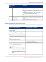
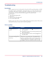
The output locations
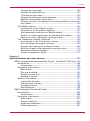
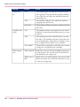
The output locations
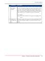
Introduction
The machine supports several output locations for the printed jobs. The default configuration of your machine contains a stacker and the system output. The finisher and the
stacker/stapler are optional output locations. Furthermore, you can connect several optional external finishers to the machine.
Note:
You need the optional finisher, the optional stacker/stapler or another optional external
finisher to staple the jobs.
Illustration
4
3
2
6
1
5
[13] The output locations
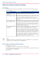
Overview of the output locations
Description of the output locations#
1
Component
Description
'Stacker'
The stacker is the default output location of the machine. The
stacker capacity is 6,000 sheets, in 2 stacks of 3,000 sheets each
(80 g/m² or 20 lb. bond).
The stacker does not contain staple cartridges. Therefore, the
stacker cannot be the output location for jobs that require staples.
Chapter 4 - Overview of the system components
33
The output locations
2
Component
Description
'System output'
The system output is the output location for the following
prints.
• Error prints
• Sample prints
• Configuration reports
• Job tickets
• The test sheets for the media registration.
Make sure that you regularly remove the sheets from the system
output.
3
'Finisher' (optional)
The optional finisher contains the following output trays.
• 3 output trays
• 1 upper output (see no. 4 below)
The finisher contains 2 staple cartridges to staple the jobs. The
3 output trays can receive A4, Letter and similar media sizes.
Stapled jobs (A4, Letter and similar media sizes only) go into
the output trays. The total capacity of the output trays is 3,700
sheets (80 g/m² or 20 lb bond).
Note:
The output trays cannot receive tab sheets.
4
'Finisher upper output'
The finisher upper output is part of the finisher. The upper
output can receive all formats. However, the upper output is
mainly intended for large media or jobs with mixed size media.
The maximum capacity of the upper output is 500 sheets (80
g/m² or 20 lb bond).
Note:
The upper output does not contain staple cartridges.
Therefore, the upper output cannot be the output location for jobs that require staples.
34
Chapter 4 - Overview of the system components
The output locations
5
Component
Description
'Stacker/stapler'(iMFS) optional
The optional stacker/stapler contains 1 staple cartridge to staple
the jobs. The staple cartridge can staple your document with 1
or 2 staples. The stacker/stapler can stack and staple various
media sizes. The device supports the stapling of mixed media
sizes, as long as the width of the media is the same. The capacity
of the lower tray is 2,000 sheets (80 g/m² or 20 lb bond).
Note:
The stacker/stapler does not support the stapling of tab
sheets.
6
'Stacker/stapler upper output'
The upper output is the upper tray of the stacker/stapler. The
capacity of the upper output is 250 sheets (80 g/m² or 20 lb
bond).
Chapter 4 - Overview of the system components
35
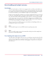
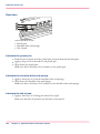
The paper modules
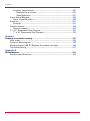
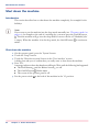
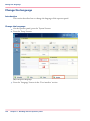
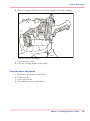
The paper modules
Introduction
The paper trays contain the media that are required for the print jobs. The default configuration of the machine contains 1 paper module with 4 paper trays. You can add 1 or
2 more paper modules to the machine. Then the total number of paper trays is extended
to 8 or 12 respectively. You can find more information about the capacities of the paper
trays and the supported media size in the appendix of this manual.
This section describes the control panel on each paper module.
Note:
You can use the control panel on the paper modules to open the paper trays and load
the media. However, the recommended way to open the paper trays and assign the media
is via the 'Schedule' view. You can also open the paper trays and/or assign the media via
the 'Trays' view (see‘Assign the media to a paper tray’ on page 99).
Illustration
5
1
1
2
3
4
2
3
4
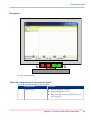
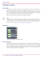
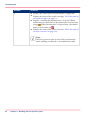
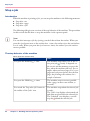
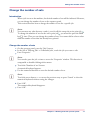
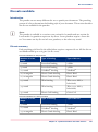
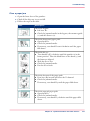
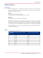
[14] The control panel on the paper modules
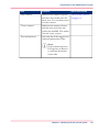
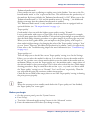
The control panel
Each paper module contains a control panel next to the upper paper tray. The control
panel consists of 4 sections that correspond with the 4 paper trays. Each section displays
the current filling level of the corresponding paper tray. Furthermore, the control panel
indicates whether the media in the paper tray is assigned or not. The following table describes the various parts of the control panel.
36
Chapter 4 - Overview of the system components
The paper modules
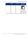
The parts of the control panel#
Number
Description
1
The LEDs indicate the current amount of sheets in the corresponding paper tray. Each lit-up LED indicates the presence of about 100
sheets (based on media of 80 g/m2 or 20 lb bond).
2
Press the button to open the corresponding paper tray. You can
only open 1 paper tray at a time.
3
When the check mark is green, the media in the paper tray is defined.
The system knows which media is in the paper tray.
4
When the arrows are red, the media in the paper tray is not defined.
The system does not know which media is in the paper tray. The
'Trays' view on the operator panel indicates that no media is assigned
to the paper tray.
5
The 'Not assigned' button. This button applies to the paper tray
where you just put the media.
You can press the 'Not assigned' button when you load a new media
type into a paper tray without defining this media type on the operator panel first. Then the printer cannot accidentally use the media
in this paper tray before the media is correctly defined on the operator panel. You can define the media type in the 'Trays' view on the
operator panel later (see ‘Assign the media to a paper tray’ on page
99).
Note:
Make sure that the paper tray is open when you press the
'Not assigned' button.
Chapter 4 - Overview of the system components
37
The paper modules
38
Chapter 4 - Overview of the system components
Chapter 5
Working with the operator
panel
The dashboard
Introduction
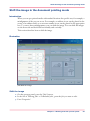
The dashboard
Introduction
The dashboard is the upper blue part of the operator panel. The dashboard is always visible,
irrespective of the current view ‘The operator panel’ on page 28. The dashboard gives the
following feedback.
• The status of the system
• The current process
• Instructions for the operator
• The status of the supplies
• The status of the external finisher, if applicable
• Whether maintenance is required.
• The 'Resume' button after you stopped the printer.
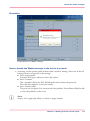
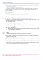
Illustration
The following illustration shows the dashboard while the machine is busy. The vertical
status bar is green. No action is required.
[15] The dashboard - No action is required
The following illustration shows the dashboard while the machine is busy. The vertical
status bar is orange. Next to the status bar, the dashboard displays a message that indicates
which action is required soon.
[16] The dashboard - Action is required soon
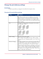
The parts of the dashboard
The dashboard#
40
Number
Function
1
Display the status of the machine, for example 'Initializing...',
'Printing...' or 'Printing will stop...'. Each status message can
have a sub-message with additional information.
Chapter 5 - Working with the operator panel
The dashboard
Number
Function
2
Display the file name of the current job (for document printing)
or current stream (for stream printing). Furthermore, the
progress of the current job is displayed.
For document printing, the counter can display the following
information.
• Set X of Y
• Sheet X of Y or Sheet X.
X represents the current status of the print job. Y represents the
total number of sets or sheets of a print job.
When the sorting method for a job is set to 'By set', and a set
contains at least 40 pages, then the dashboard displays the set
count (Set X of Y) and the sheet count (Sheet X of Y) for the
set. If a set contains less than 40 pages, then the dashboard only
displays the set count (Set X of Y).
If the sorting method for a job is set to 'By page', or when you
print stream jobs, the dashboard only displays a sheet count.
3
Display the action that you must do now or soon. The colors
of the vertical status bar at the left-hand side match the colors
of the operator attention light ‘The operator attention light’ on
page 31. When the color is orange or red, a message indicates
the required action.
Orange means that action is required soon. How long before
an upcoming action the operator panel starts to display the
message depends on the defined warning time ‘Change the
warning time’ on page 128.
Red means that action is required now.
Note:
The operator panel can only display one message at a
time. When there are more messages, the operator
panel displays the first required or most important
message.
Chapter 5 - Working with the operator panel
41
The dashboard
Number
Function
4
• Display the status of the external finisher, if applicable.
• Display the status of the staple cartridges ‘Check the status of
the staple cartridges’ on page 111.
• Display a warning that maintenance is required. When
maintenance is required soon, the maintenance icon becomes
orange . When maintenance is required now, the maintenance icon becomes red .
• Display the status of the toner reservoirs ‘Check the status of
the toner reservoirs’ on page 109.
Note:
Only key operators who received the special maintenance training are allowed to do maintenance tasks.
42
Chapter 5 - Working with the operator panel
Introduction to the 'Schedule' view
The Schedule view
Introduction to the 'Schedule' view
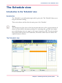
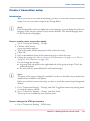
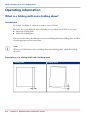
Introduction
The 'Schedule' is your daily planning board for print jobs. The 'Schedule' helps you to
keep the machine running.
This section shows and describes the main parts of the 'Schedule'.
Note:
The descriptions of the colors of the bars and the indication of the required amount of
sheets are only valid for document printing. For streaming jobs , all the bars remain
grey until the paper trays are empty or the output locations are full. Then the machine
stops and the bars become red. Furthermore, the media toolbar does not indicate the
required amount of sheets.
The 'Schedule' view
[17] The 'Schedule' view
Chapter 5 - Working with the operator panel
43
Introduction to the 'Schedule' view
1. The jobs pane
The jobs pane shows the jobs on a timeline. The width of the job corresponds to the
(remaining) print time. A vertical line separates the jobs. The vertical line moves to the
left as the printing of a job progresses.
An icon and the job name represent a job. The icon indicates the state of the job, for example printing .
Furthermore, the icon indicates the stop moments of the machine. For example, when
the setting 'Confirm start of job' in the workflow profiles (see list of references below) is
set to 'On' or when you use the 'Stop after job' function.
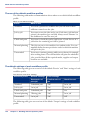
2. The 'Required media' pane
The 'Required media' pane displays the media that are required for each scheduled job.
For each required media, the media properties are displayed (see list of references below).
The bars show the availability of the media. The bars can have the following colors.
The colors of the bars#
Color of the bar
Description
Green
The required media is available.
Orange
The media is required in the future, but not available then. For
example because the paper trays do not contain sufficient sheets
of the required media.
Yellow
The system cannot determine the exact number of sheets that
is available in the paper trays.
Red
The media is required now, but not available. The job can only
start when you load the required media.
When you print small jobs, the bars for these jobs may not be completely visible. To
prevent that you do not see the status of these small jobs, the operator panel can show
the following images.
#
NOTE
When you set the zoom control (5) to a shorter time-scale, in most cases the operator
panel will display bars for these small jobs.
The possible display of small jobs#
Image
Description
Green. The required media is available.
44
Chapter 5 - Working with the operator panel
Introduction to the 'Schedule' view
Image
Description
Orange. The media is required in the future, but not available
then. For example because the paper trays do not contain sufficient sheets of the required media.
Red. The media is required now, but not available. The job can
only start when you load the required media.
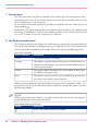
3. The media toolbar
The media toolbar displays the following information for the media that is selected in
the 'Required media' pane. Furthermore, the media type toolbar contains the 'Load'
button to load and assign the required media.
The icons in the media toolbar#
Icon
Description
The list of 'Required media' shows the required media for the
scheduled jobs. When the paper module indicator is completely
grey, this means that not one of the required media is available
in the paper trays.
The list of 'Required media' shows the required media for the
scheduled jobs. When a paper tray is highlighted in green, the
highlighted paper tray contains a media that is required by one
of the scheduled jobs.
The list of 'Required media' shows the required media for the
scheduled jobs. When a paper tray is highlighted in blue, the
highlighted paper tray contains the media that is also highlighted
in blue in the list of 'Required media'.
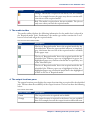
4. The output locations pane
The output locations pane displays the output locations that are required for the scheduled
jobs. The bars show the availability of the output locations. The bars can have the following
colors.
The colors of the bars#
Color of the bar
Description
Green
The output location is required and available.
Orange
The output location is required in the future, but not available
then. For example, because the output location will be full soon.
Chapter 5 - Working with the operator panel
45
Introduction to the 'Schedule' view
Color of the bar
Description
Red
The output location is required now, but not available. For example, because the output location is full.
Gray
The output location is required, but availability is unknown.
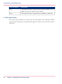
5. The zoom control
The zoom control enables you to adjust the time scale visible in the 'Schedule'. When
you press the zoom button, a drop-down list appears. Then you can select the desired
time scale.
46
Chapter 5 - Working with the operator panel
Load the media
Load the media
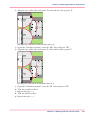
Introduction
This section describes how to load the media into a paper tray.
When you load the media via the 'Load' button in the 'Schedule', the paper tray is automatically assigned to the correct media.
When you load and assign the media via the 'Assign' button in the 'Trays' view, you must
assign the paper tray to the loaded media manually.
When no external finisher is connected to the machine, you must put all the media types
face up and header up into the paper trays. The tabs of tab sheets must be at the righthand side. When an external finisher is connected to the machine, it is possible that you
must put the media into the paper trays in a different way. Refer to the documentation
of the external finisher for more information about how to place the media.
When to do
• The 'Schedule' displays a red bar next to a required media. The red bar indicates that
a scheduled job now requires a media that is not available in the paper trays.
• The 'Schedule' displays an orange bar next to a required media. The orange bar indi-
cates that a scheduled job requires media which is either not available in the paper
trays or which is available, but not in sufficient quantity to finish the job.
• The current job requires more of the same media than is currently loaded in the paper
trays. You can add more of the required media into another paper tray.
• You already want to load and assign media that are required for the next job (work
ahead).
Caution:
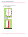
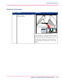
Always put the stack of media aligned with the left-hand side of the paper guides inside
the paper trays, as indicated on the sticker inside the paper trays.
Illustration
SR
SR
[24] The sticker inside the paper trays indicates how to load the media
Chapter 5 - Working with the operator panel
47
Load the media
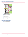
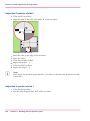
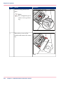
Load the media
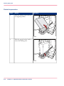
1. Put a small stack of media into the paper tray.
2. Press the green handle on the right-hand guide and push the guide against the edge of
the media.
3. Turn the green knob to adjust the front guide and the rear guide.
4. Put the rest of the media on top of the small stack.
Note:
If you want to assign the media later you must press the 'Not assigned' button ‘The paper
modules’ on page 36, as indicated on the right-hand side of the sticker.
48
Chapter 5 - Working with the operator panel
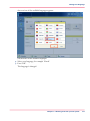
Load media via the 'Schedule' view
Load media via the 'Schedule' view
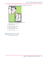
Introduction
When the 'Schedule' view is available on your printer, you can load and assign the required
media directly in the 'Schedule' section.
Note:
When you load a different media size, you must also set the paper guides inside the paper
tray to the correct dimensions.
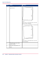
Illustration
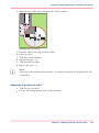
[25] Load the media
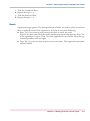
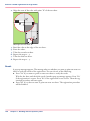
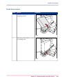
How to load and assign media via the 'Schedule' view
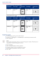
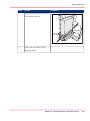
1. Touch the button for the media you want to load, for example Special A4.
2. Press 'Load'.
The 'Trays' view appears.
3. On the screen, touch the paper tray where you want to load the media.
Chapter 5 - Working with the operator panel
49
Load media via the 'Schedule' view
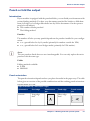
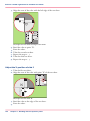
4. Touch 'OK' to open the paper tray.
5. Load the media into the paper tray.
The system assumes you loaded the selected media type, in this example Special A4. The
system will automatically assign Special A4 to that paper tray.
Note:
You can always change the assigned media type later by touching the 'Assign' button.
6. Gently close the paper tray.
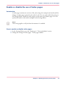
•Introduction to the Schedule view, on page 43
50
Chapter 5 - Working with the operator panel
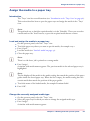
Instructions for printing to the stacker/stapler (iMFS)
Instructions for printing to the stacker/stapler (iMFS)
Introduction
Note:
This section only applies to the use of oriented media and tab sheets in combination
with the optional stacker/stapler (iMFS).
The machine supports oriented media. Oriented media are media of which the front side
differs from the back side. An example of oriented media is media with a company logo.
If you use oriented media and print to the optional stacker/stapler, you must place the
media into the paper trays as follows:
• Face up and header down (for long-edge feed)
The face of the media, for example a company logo, is visible and point towards the
front of the printer.
• Face up and header to the left (for short-edge feed).
The face of the media is visible and points towards the left-hand side of the printer.
This orientation makes sure that the documents are stapled at the correct position.
Special instructions for the use of oriented media
When a job contains oriented media but no tab sheets, you must put this media header
down into the paper tray. The media must align with the header-down orientation of the
printed images (header down for long-edge feed and header to the right for short-edge
feed).
Special instructions for the use of tab sheets
When a job contains tab sheets, you must do the following.
• Put all the oriented media for the job, including the tab sheets, header up and header
to the left (for short-edge feed) into the paper tray.
• Temporarily change the default media orientation on the Controller to 'Header-up'.
To do this, you must go to the setting 'Preferences' - 'Print job defaults' - 'Stacker/stapler (iMFS)' or 'Stacker/stapler upper output' - 'Header orientation'. There you can
click the radio button for 'Header-up'.
Jobs that contain tab sheets are sent to the stacker/stapler when no stacker is present.
When a stacker is present, the jobs are sent to the stacker to improve the stack quality.
Chapter 5 - Working with the operator panel
51
Stop a job
Stop a job
Introduction
When the machine is printing a job, you can stop the machine at the following moments.
• Stop after a set
• Stop after a page
• Stop after a job.
The following table gives an overview of the stop behavior of the machine. The procedures
in this section describe how to stop the machine via the operator panel.
Note:
You can also interrupt a job by ejecting a stack of sheets from the stacker. When you
press the eject button next to the stacker door 1 time, the stacker ejects the stack when
a set is ready. When you press the eject button 2 times, the stacker ejects the stack as
soon as possible.
The stop behavior of the machine
When does the machine stop#
When
Then
You press the Hold key
1 time
The machine stops when a set of the active print job is ready. It depends on
the set size and the moment you press the
key, when the machine will stop. For example, when you have a large set of 1,000
pages and you press the key after the first
page, the printing will continue for a
couple of minutes.
You press the Hold key
2 times
The machine stops as soon as possible
(after a page, in most cases within 30
seconds).
You touch the 'Stop after job' button in
the toolbar of the 'Jobs' view
52
Chapter 5 - Working with the operator panel
The machine stops when the selected job
is ready.
The 'Jobs' view displays a horizontal red
and white stop bar below the selected job.
The 'Schedule' view displays a vertical
stop bar behind the selected job.
Stop a job
When
Then
The 'Check first set' setting in a 'Workflow profile' is 'On' ‘Work with the workflow profiles’ on page 121 and this setting
is also enabled in the job
The machine stops each time the first set
of a print job is ready. You can check the
first set before you continue the print job.
The 'Confirm start of job' setting in a
'Workflow profile' is 'On'
The machine stops each time at the start
of a job. You must start each job manually.
Note:
When you print streaming jobs or jobs that consist of 1 large set, you must always
press the Hold key 2 times to stop the machine as soon as possible.
Stop after a set
1. Press the Hold key 1 time.
The red LED of the Hold key starts to blink.
The machine stops when a set of the active print job
is ready.
Stop after a page
1. Press the Hold key 2 times.
The red LED of the Hold key starts to blink.
The machine stops as soon as possible.
Note:
The memory of the machine can contain up to 50 pages. Therefore, it is possible for
the machine to print more than a set before the machine stops.
Stop after a job
1. In the list of 'Scheduled jobs' in the 'Jobs' view, touch the job after which the machine
must stop.
2. Press 'Stop after job'.
The machine stops as soon as the selected job has been printed. A red and white stop bar
indicates that the stop-after-job function is active. Touch 'Stop after job' again to remove
the stop bar and continue printing.
Chapter 5 - Working with the operator panel
53
Stop a job
Stop a streaming job or transaction stream
1. Press the Hold key 1 time.
The red LED of the Hold key starts to blink.
The printer will continue to print the pages that are already in the buffer. When the
buffer is empty, the printer stops.
54
Chapter 5 - Working with the operator panel
Introduction to the 'Jobs' view
The Jobs view
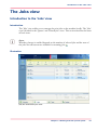
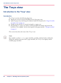
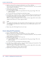
Introduction to the 'Jobs' view
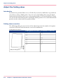
Introduction
The 'Jobs' view enables you to manage the print jobs on the machine locally. The 'Jobs'
view is divided in the 'Queues' and 'Printed jobs' views. This section describes the items
of both views.
Note:
Whether a button is enabled depends on the number of selected jobs and the state of
the jobs. Not all buttons are available for streaming jobs .
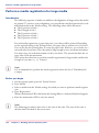
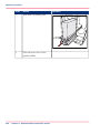
Illustration
[26] The 'Scheduled jobs' view
Chapter 5 - Working with the operator panel
55
Introduction to the 'Jobs' view
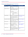
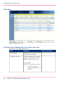
The items of the 'Scheduled jobs' view of the 'Jobs' view
Description of the 'Scheduled jobs' view#
Item
Function
'Scheduled jobs'
Display the active print job
and the jobs that are scheduled
for printing.
'Properties' button
Check or change the properties
of a job. The button is only enabled when you select 1 job.
More information
Note:
You can also press a job
2 times to check or
change the properties of
that job.
56
'To top' button
Give priority to a scheduled job.
The job is printed when the active print job is ready. The
button is only enabled when you
select 1 job.
‘Give priority to a print
job’ on page 65
'Stop after job' button
Stop the machine after a selected
job. The button is only enabled
when you select 1 job.
‘Stop a job’ on page 52
'Delete' button
Delete the selected job of jobs.
The button is enabled when you
select 1 or more jobs.
‘Delete print jobs’ on
page 67
'Move' button
Move a job from the list of
'Scheduled jobs' to the list of
'Waiting jobs'.
The button is enabled when you
select 1 or more jobs.
‘Print a scheduled job
later’ on page 69
'Ticket' button
Print an overview of the main
job settings and job parameters.
The button is only enabled when
you select 1 job.
‘Print a job ticket’ on
page 71
Chapter 5 - Working with the operator panel
Introduction to the 'Jobs' view
Item
Function
More information
'Select' button
Select a number of jobs at the
same time. You can use one of
the following:
• 'All': select all the jobs in the
list.
• 'None': deselect all the jobs
in the list.
• 'Invert selection': turn the selected jobs into deselected
jobs, and the other way
round.
• 'Jobs with available media':
select all the jobs for which
the media are currently available in the paper trays.
• 'Jobs with label': select all the
jobs with a certain label.
‘Select more than one job
for printing’ on page 74
‘Select more than one job
for printing’ on page 74
'Print now' button
Print an urgent job immediately.
The job is printed when the
current set of the active print job
is ready. The button is only
enabled when you select 1 or
more jobs.
‘Print an urgent job immediately’ on page 66
Chapter 5 - Working with the operator panel
57
Introduction to the 'Jobs' view
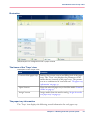
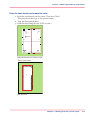
Illustration
[27] The 'Waiting jobs' view
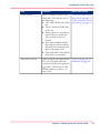
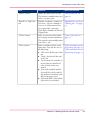
The items of the 'Waiting jobs' view of the 'Jobs' view
Description of the 'Waiting jobs' view#
Item
Function
'Waiting jobs'
Display the jobs that are not yet
scheduled for printing.
'Properties' button
Check or change the properties
of a job. The button is only enabled when you select 1 job.
Note:
You can also press a job
2 times to check or
change the properties of
that job.
58
Chapter 5 - Working with the operator panel
More information
Introduction to the 'Jobs' view
Item
Function
More information
'Delete' button
Delete the selected job or jobs .
The button is enabled when you
select 1 or more jobs.
‘Delete print jobs’ on
page 67
'Bundle' or 'Split' button
Bundle: Combine a number of
jobs into 1 job, for example to
create a set of documents that
are required for a meeting.
Split: Split a bundle job into the
original jobs.
‘Bundle jobs in the list of
'Waiting jobs' ’ on page
72
'Ticket' button
Print an overview of the main
job settings and job parameters.
The button is only enabled when
you select 1 job.
‘Print a job ticket’ on
page 71
'Select' button
Select a number of jobs at the
same time. You can use one of
the following:
• 'All': select all the jobs in the
list.
• 'None': deselect all the jobs
in the list.
• 'Invert selection': turn the selected jobs into deselected
jobs, and the other way
round.
• 'Jobs with available media':
select all the jobs for which
the media are currently available in the paper trays.
• 'Jobs with label': select all the
jobs with a certain label.
‘Select more than one job
for printing’ on page 74
‘Select more than one job
for printing’ on page 74
Chapter 5 - Working with the operator panel
59
Introduction to the 'Jobs' view
Item
Function
More information
'Proof' button
Print 1 copy of a job to check
whether the result of the print
job meets your expectation. The
button is only enabled when you
select 1 job.
‘Make a proof’ on page
70
Note:
The proof print is not
subtracted from the
number of sets you defined for this job.
'Print' button
Move a job from the list of
'Waiting jobs' to the list of
'Scheduled jobs'.
The button is enabled when you
select 1 or more jobs.
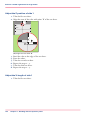
Illustration
[28] The 'Printed jobs' view
60
Chapter 5 - Working with the operator panel
‘Schedule a waiting job
for printing’ on page 63
Introduction to the 'Jobs' view
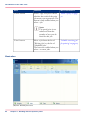
The items of the 'Printed jobs' view of the 'Jobs' view
Description of the 'Printed jobs' view#
Item
Function
More information
'Printed jobs'
Display the jobs that were printed successfully. The system only
moves the printed jobs to the list
of 'Printed jobs' when the setting
'Printed jobs' in the Settings
Editor is enabled.
'Properties' button
Check or change the properties
of a job. The button is only enabled when you select 1 job.
Note:
You can also press a job
2 times to check or
change the properties of
that job.
'Delete' button
Delete the selected job or jobs .
The button is enabled when you
select 1 or more jobs.
‘Delete print jobs’ on
page 67
'Copy' button
Send a copy of a job that has
been printed before to the list of
'Waiting jobs' to reprint the job.
The button is enabled when you
select 1 or more jobs.
‘Reprint a job’ on page
64
'Ticket' button
Print an overview of the main
job settings and job parameters.
The button is only enabled when
you select 1 job.
‘Print a job ticket’ on
page 71
Chapter 5 - Working with the operator panel
61
Introduction to the 'Jobs' view
62
Item
Function
More information
'Select' button
Select a number of jobs at the
same time. You can use one of
the following:
• 'All': select all the jobs in the
list.
• 'None': deselect all the jobs
in the list.
• 'Invert selection': turn the selected jobs into deselected
jobs, and the other way
round.
• 'Jobs with available media':
select all the jobs for which
the media are currently available in the paper trays.
• Use 'Jobs with label' to select
all the jobs with a certain label.
‘Select more than one job
for printing’ on page 74
‘Select more than one job
for printing’ on page 74
Chapter 5 - Working with the operator panel
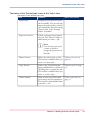
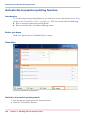
Schedule a waiting job for printing
Schedule a waiting job for printing
Introduction
The destination of jobs is determined by the selected workflow profile. When jobs go to
the list of 'Waiting jobs', you must manually send the jobs to the print queue (list of
'Scheduled jobs'). This enables you to keep full control of all jobs that must be printed.
How to schedule a waiting job for printing
1. Touch 'Jobs' -> 'Queues'.
2. If collapsed, first touch to expand the desired list of 'Waiting jobs'.
3. Touch the job(s) you want to print or use the 'Select' button to make a selection.
To undo the multiple selection and only select 1 job, you must touch that job for 2 seconds.
4. Press 'Print'.
The job is moved to the bottom of the list of 'Scheduled jobs'.
•Work with the workflow profiles, on page 121
Chapter 5 - Working with the operator panel
63
Reprint a job
Reprint a job
Introduction
Note:
The following description is only applicable when the setting 'Printed jobs' in the Settings
Editor is enabled.
Print jobs that have been completed are moved from the list of 'Scheduled jobs' list to
the list of 'Printed jobs'. The 'Printed jobs' list helps you to reprint jobs quicker and easier.
What you need to know about the list of Printed jobs
• When you want to reprint a job, the selected job is always copied to the list of 'Waiting
jobs' first.
• You cannot change the job settings in the list of 'Printed jobs'. This is only possible
in the list of 'Waiting jobs'.
• You cannot reprint streaming jobs.
• The list of 'Printed jobs' does not store proof prints, system jobs and jobs that were
stopped or deleted.
• When you shut down the printer all jobs remain present in the list of 'Printed jobs'.
• The list of 'Printed jobs' can only store jobs. To prevent the disk of your system from
becoming full, jobs must be deleted manually or automatically on a regular basis. In
the Settings Editor, you can indicate the cleaning period, then the clean-up is carried
out at midnight or at the next start-up (in general the next morning).
• If E-shredding is enabled, the jobs will be shredded after removal from the list of
'Printed jobs'.
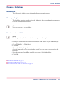
How to reprint a job
1. Touch 'Jobs' -> 'Printed jobs'.
2. Touch the job(s) you want to reprint or use the 'Select' button to make a selection.
To undo the multiple selection and only select 1 job, you must touch that job for 2 seconds.
3. Press 'Copy'.
4. Touch 'Queues' -> 'Waiting jobs'.
5. Touch the job you want to reprint.
6. Touch 'Properties' if you want to change the settings, for example the number of sets.
7. Press 'Print'.
64
Chapter 5 - Working with the operator panel
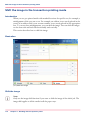
Give priority to a print job
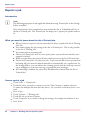
Give priority to a print job
Introduction
When you want to print a job as soon as possible, but not necessarily immediately, you
must use the 'To top' function. The 'To top' function moves the selected job to the second
position in the list of 'Scheduled jobs', below the active print job . The job will be
printed when the active print job is ready.
How to give priority to a print job
1.
2.
3.
4.
Touch 'Jobs' -> 'Queues'.
If collapsed, first touch to expand the list of 'Scheduled jobs'.
Touch the job to which you want to give priority.
Press 'To top'.
•Print an urgent job immediately, on page 66
Chapter 5 - Working with the operator panel
65
Print an urgent job immediately
Print an urgent job immediately
Introduction
When a job must be printed urgently, you can give that print job priority over all other
print jobs. The 'Print now' button allows you to print a job immediately. When you use
the 'Print now' button, the active print job will be paused as soon as the current set is
ready.
To print a job as soon as possible but not immediately, you can use the 'To top' function.
Location of the 'Print now' button
The 'Print now' button is available in the 'Scheduled jobs' view.
Note:
To give priority to a job in the list of 'Waiting jobs', you must first touch 'Print' to send
the job to the list of 'Scheduled jobs'. There you can select the job and touch 'Print
now'.
To give priority to a job in the list of 'Printed jobs', you must first reprint the job (see
‘Reprint a job’ on page 64). The job is sent to the list of 'Waiting jobs'. From there, you
must send the job to the list of 'Scheduled jobs'. There you can select the job and touch
'Print now'.
Note:
If the output location of the priority print job is the same as the active print job, the
priority print job comes on top of the last printed set of the active job.
How to print an urgent job immediately
1.
2.
3.
4.
Touch 'Jobs' -> 'Queues'.
If collapsed, first touch to expand the list of 'Scheduled jobs'.
Touch the job which you want to print immediately.
Press 'Print now'.
The urgent job appears at the top of the list of 'Scheduled jobs'. The active print job
is paused as soon as the current set is ready and becomes second in the list.
•Give priority to a print job, on page 65
66
Chapter 5 - Working with the operator panel
Delete print jobs
Delete print jobs
Locations from which jobs can be deleted
You can delete jobs from the following locations.
• List of 'Printed jobs' (if this function is enabled in the Settings Editor).
• List of 'Scheduled jobs'.
• List of 'Waiting jobs'.
Note:
You can only delete the active print job in the list of 'Scheduled jobs' when the
printer is on hold. If necessary, press the Hold key 2x to put the printer on hold.
Select the jobs you want to delete
The table below describes your options to select one or more jobs.
Select one or more jobs that you want to delete#
What to delete?
How to do?
One or more separate
jobs
Go to the correct location described above, then touch the
jobs one by one.
All jobs
Go to the correct location, then touch 'Select' -> 'All'.
'Jobs with available media'
Go to the correct location, then touch 'Select' -> 'Jobs with
available media'.
'Jobs with label'
Go to the correct location, then touch 'Select' -> 'Jobs with
label'.
Note:
For the list of 'Printed jobs', you can indicate in the Settings Editor that the list must
be cleaned automatically at specified times. The factory default is 1 day. Furthermore,
in the Settings Editor you can manually clean up the jobs in the lists of 'Printed jobs',
'Scheduled jobs' and 'Waiting jobs'.
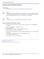
How to delete the jobs
1. Go to one of the following locations.
• Touch 'Jobs' -> 'Queues'
If collapsed, first touch to expand the list of 'Scheduled jobs' or 'Waiting jobs'.
• Touch 'Jobs' -> 'Printed jobs'
Chapter 5 - Working with the operator panel
67
Delete print jobs
2. Select the jobs you want to delete.
3. Press 'Delete'.
A message appears.
When
you are sure that you want to delete the selected job(s), touch 'Yes'.
4.
68
Chapter 5 - Working with the operator panel
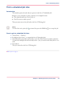
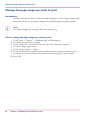
Print a scheduled job later
Print a scheduled job later
Introduction
The machine prints the jobs that are present in the list of 'Scheduled jobs'.
However, you can decide to print a job later, for example because:
• The required media are out of stock, or
• You first want to make a proof.
Then you must move the job back to the list of 'Waiting jobs'.
Note:
To select the active print job
you must first press the Hold key
2x to stop the job.
How to print a scheduled job later
1. Touch 'Jobs' -> 'Queues'.
2. If collapsed, first touch to expand the list of 'Scheduled jobs'.
3. Touch the job(s) you want to print later or use the 'Select' button to make a selection.
To undo the multiple selection and only select 1 job, you must touch that job for 2 seconds.
4. Press 'Move'.
The job is moved to the list of 'Waiting jobs'.
•Make a proof, on page 70
Chapter 5 - Working with the operator panel
69
Make a proof
Make a proof
Introduction
You can make a proof to check whether the quality and the layout of the output meet
your expectations. When you use the 'Proof' function, the machine prints 1 copy of the
job. You can only make a proof for a job in the list of 'Waiting jobs'.
This section describes how to make a proof.
Note:
When you make a proof, the printed set is not subtracted from the defined total number
of sets for a job. For example, if you need 10 sets the printer will still print 10 sets after
you made the proof. This is different from the checking of the first set (see ‘Check the
first set’ on page 78).
Make a proof
1. On the operator panel, press the 'Jobs' button.
2. In the list of 'Waiting jobs', touch the job of which you want to make a proof.
Note:
You can select more than 1 job at a time.
3. Press 'Proof'.
A copy of the job goes to the bottom of the list of 'Scheduled jobs'.
The original job remains in the list of 'Waiting jobs'.
You can recognize a proof by the magnifying glass on the job icon .
70
Chapter 5 - Working with the operator panel
Print a job ticket
Print a job ticket
Introduction
Job tickets are used to transfer settings from an application to the printer. It can be convenient to print a job ticket before printing a job, to get an overview of the main job
characteristics.
Job tickets can contain the following information, for example.
• Job name.
• Job owner.
• Job destination.
• Job settings such as the number of sets.
• Required media.
The 'Ticket' button, which allows you to print a job ticket, is available in various locations
on the operator panel.
Where to find the 'Ticket' button
The 'Ticket' button is available at the following locations.
• List of 'Printed jobs' (if this function is enabled in the Settings Editor).
• List of 'Scheduled jobs'.
• List of 'Waiting jobs'.
How to print a job ticket
1. Press 'Jobs'.
2. Go to one of the locations mentioned above.
3. Touch the job for which you want to print the job ticket.
Note:
You can only print a job ticket for 1 job at a time.
4. Press 'Ticket'.
A message appears which confirms that the job ticket is printed.
Chapter 5 - Working with the operator panel
71
Bundle jobs in the list of 'Waiting jobs'
Bundle jobs in the list of 'Waiting jobs'
Introduction
The bundle function allows you to combine 2 or more jobs into 1 new job. For example,
this can be convenient when the participants of a meeting need several documents in a
specific order. Often, the required documents are sent from several workplaces to the
printer in advance. Normally, this means that you must print the documents first and
sort or staple them later. By using the bundle function you can determine the order of
the documents before printing and print all documents in the correct order in only 1
print job.
Important information about the bundle function
• You can only bundle print jobs that are currently in the list of 'Waiting jobs'.
• You can change a number of settings for the bundled job via the 'Properties' window.
• By default, the number of sets for a bundled job is 1. So before printing, you must
first indicate the required number of sets.
• When you stop a job after a set, the printing stops after 1 copy of the complete bundle.
• The jobs in a bundle are accounted separately under the account ID of the original
jobs.
• All the jobs in the bundle must have the same output location. Otherwise, the operator
panel displays a warning message. To change the output location, you must first split
the bundled job, then change the individual job settings and finally bundle the jobs
again.
Main actions on the bundle function
The table below describes the main actions you can carry out with regard to the bundle
function.
Main bundle functions#
72
Main actions
Description
'Bundle'
When you touch 'Bundle' after selecting 2 or more jobs, a
new job is created that contains the original jobs. The new
job is added to the bottom of the list of 'Waiting jobs'. The
original jobs are removed from the list. The new job gets
a new name that is based on the name of the first job in
the bundle.
Chapter 5 - Working with the operator panel
Bundle jobs in the list of 'Waiting jobs'
Main actions
Description
'Split'
When you touch 'Split' after selecting a bundled job, the
job is split into the original, separate jobs. The bundled job
is removed. The separate jobs are added to the bottom of
the list of 'Waiting jobs'. You can use the 'Split' function
to correct mismatched settings, for example.
Change job settings
The 'Properties' window gives access to a pane where you
can do the following.
• Change a number of job settings.
• Change the order of the jobs in the bundle.
'Delete'
Delete the job.
'Ticket'
Print the job ticket of the job.
'Proof'
Print 1 copy of the job first to check if the result meets your
expectations.
How to combine print jobs
1. Touch 'Jobs' -> 'Queues' -> 'Waiting jobs'.
2. Touch the jobs you want to combine.
Note:
If all jobs you want to combine have the same label, you can also touch 'Select' -> 'Jobs
with label' to select all the required jobs at once.
3. Press 'Bundle'.
The operator panel displays an overview of the bundled job.
4. If necessary, use the 'Up' and 'Down' buttons to change the job order.
5. If necessary, change the job settings such as 'Number of bundles'.
6. Press 'OK'.
•Delete print jobs, on page 67
•Print a job ticket, on page 71
•Make a proof, on page 70
Chapter 5 - Working with the operator panel
73
Select more than one job for printing
Select more than one job for printing
Introduction
The table below describes the possibilities to select more than one job for printing.
Select more jobs#
Options
Description
Select 2 or more jobs
manually
Touch the jobs you want to print one by one.
'Select' button - 'All'
All jobs in the list of 'Waiting jobs' are printed. The order
in the list of 'Waiting jobs' determines the print order.
However, in the list of 'Scheduled jobs' you can give priority to a job.
'Select' button - 'Jobs
with available media'
All jobs for which the required media are currently available
in the paper trays, will be printed. This improves the productivity, because you must not change the required media
during printing. You may only need to add more of the
currently available media types.
'Select' button - 'Jobs
with label'
A label is a name or tag that helps you to identify certain
jobs on the operator panel. When a job is sent to the
printer, the person who submits the job can add a label to
that job. The label can be any name that helps to identify
certain jobs. A label is not connected to job settings. The
label can be defined in the printer driver, in a job ticket or
via an automated workflow. For example, the label ‘Customer XYZ’ can be added to jobs. Then you can select and
print all the jobs for 'Customer XYZ' at once.
Note:
Automated workflows can be defined through the Settings Editor. You can find more
information in the online help of the Settings Editor.
How to select more than one job for printing
1. Touch 'Jobs' -> 'Queues'.
2. If collapsed, first touch to expand the list of 'Waiting jobs'.
3. Touch the jobs you want to print one by one, or make a selection using the 'Select' button.
The selected jobs are highlighted.
4. Press 'Print'.
74
Chapter 5 - Working with the operator panel
Select more than one job for printing
•Give priority to a print job, on page 65
Chapter 5 - Working with the operator panel
75
Contradiction handling
Checking and changing the job properties
Contradiction handling
Be aware that if you change settings you might make contradicting settings. If you make
contradicting settings, the preview pane informs you how to solve the contradictions.
The contradicting settings are marked orange and indicate where contradictions are found.
The green check marks indicate where to find the settings that you must change to resolve
the contradictions.
76
Chapter 5 - Working with the operator panel
Change the number of sets
Change the number of sets
Introduction
When a job is sent to the machine, the desired number of sets will be indicated. However,
you can change the number of sets on the operator panel.
This section describes how to change the number of sets for a specific job.
Note:
You can enter any value between 1 and 65,000 for all jobs except the active print job .
To change the number of sets for the active print job , you must first press the Hold
key 1 time. Then you can change the number of sets. You cannot define a lower value
than the number of sets that has already been printed.
Change the number of sets
1. On the operator panel, press the 'Jobs' button.
2. In the list of 'Waiting jobs' or 'Scheduled jobs', touch the job you want to edit.
3. Press 'Properties'.
Note:
You can also press the job 2 times to access the 'Properties' window. This function is
comparable to double-clicking with a mouse.
4. Touch the 'Number of sets' button.
A numerical keyboard appears.
5. Use the numerical buttons to enter the desired number of sets.
Note:
Touch the arrow button <- to correct the previous entry or press 'Cancel' to close the
numerical keyboard without saving the changes.
6. Press 'OK'.
The numerical keyboard disappears.
7. Press 'OK'.
Chapter 5 - Working with the operator panel
77
Check the first set
Check the first set
Introduction
If you have a large print job and you want to check whether the job is printed correctly,
it is advised to check the first set before printing all other sets. When a job is sent to the
printer, the submitter can indicate in the job submission application that the first set
must be checked. However, the workflow profile that is selected on the operator panel
determines how the printer handles these requests.
Depending on the selected workflow profile, the 'Check first set' setting can have the
following values:
• 'On'
• 'Off'
• 'As in job'
When you use the 'Check first set' function, the printed set is subtracted from the indicated total number of sets for a job. For example, when you need 10 sets, the printer will
print the first set and then stop. When you continue the job, the 9 remaining sets are
printed. This is different from printing a proof.
Methods to check the first set
You can use 1 of the following methods to indicate that you want to check the first set.
• Use a workflow profile where 'Check first set' is enabled. Then the printer stops after
the first set.
• Enable the function 'Check first set' in the 'Properties' window for a specific job only.
However, you can only change the 'Check first set' setting there when a workflow
profile is selected where the 'Check first set' setting is 'As in job'.
Note:
You cannot change this setting for the active print job .
How to enable the checking of the first set
1.
2.
3.
4.
5.
78
Touch 'Jobs' -> 'Queues' -> 'Scheduled jobs' or 'Waiting jobs'.
Touch the job you want to change.
Touch 'Properties' - or touch the job 2x to open the 'Properties' window.
Touch the 'Number of sets' button.
Touch 'Check first set' when the button states 'Off'.
Chapter 5 - Working with the operator panel
Check the first set
The text changes from 'Off' to 'On'. A check mark indicates that the checking of the first
set is enabled.
6. Press 'OK'.
The 'Number of sets' button will now show a check mark.
Press
'OK'.
7.
•Work with the workflow profiles, on page 121
•Make a proof, on page 70
Chapter 5 - Working with the operator panel
79
Change the page range you want to print
Change the page range you want to print
Introduction
Usually, in the printer driver is defined whether all pages or only a range of pages must
be printed. However, you can also change this setting through the operator panel.
Note:
You cannot change this setting for the active print job .
How to change the page range you want to print
1.
2.
3.
4.
5.
6.
7.
8.
80
Touch 'Jobs' -> 'Queues' -> 'Scheduled jobs' or 'Waiting jobs'.
Touch the job you want to change.
Touch 'Properties' - or touch the job 2x to open the 'Properties' window.
Touch the 'Page range' button.
Touch 'Pages to print' -> 'Pages'.
Touch the 'From' button and enter the number of the first page you want to print.
Touch the 'To' button and enter the number of the last page you want to print.
Press 'OK'.
Chapter 5 - Working with the operator panel
Enable the separator sheets
Enable the separator sheets
Introduction
When you print jobs with many sets, it can be difficult to identify your sets in the stack
of paper.
You can separate your sets in two ways:
• By 'Offset stacking', see ‘Change the stacking method per job’ on page 83.
Each set or job will be stacked with an offset compared to the previous set or job.
• By 'Separator sheets'.
A separator sheet is a sheet that is inserted before each set. Separator sheets are handy,
for example, when you want to transport the sets in one straight stack in the original
box. You can define the media you want to use as separator sheets in the Settings Editor.
This section describes how to enable the separator sheets.
Enable the separator sheets
1. On the operator panel, press the 'Jobs' button.
2. In the list of 'Waiting jobs' or 'Scheduled jobs', touch the job you want to edit.
3. Touch the 'Separator sheets' button when the button states 'Off'.
The text changes from 'Off' to 'On'.
Chapter 5 - Working with the operator panel
81
Rename a job
Rename a job
Introduction
When you print a job, the job name is created in the application. The job name is displayed
in the 'Job name' field. However, you can rename the job.
How to rename a job
1. In the job window, touch 'Job name'.
A keyboard appears.
2. Touch 'Backspace' until the current name is deleted.
3. Touch the characters to enter a new name.
4. Press 'OK'.
82
Chapter 5 - Working with the operator panel
Change the stacking method per job
Change the stacking method per job
Introduction
The 'Offset stacking' function creates a visible distinction between sets or jobs in an
output location. The active workflow profile or the active automated workflow determines
the default type of offset stacking.
You can only change the type of 'Offset stacking' per job when the 'Offset stacking' setting
of the active 'Workflow profile' is set to 'Sets (as in job)'.
Note:
You cannot change this setting for the active print job .
Note:
Automated workflows can be defined through the Settings Editor. You can find more
information in the online help of the Settings Editor.
How to change the stacking method per job
Note:
Remember that you can only change the stacking method per job when the active
'Workflow profile' is set to 'Sets (as in job)'.
Touch 'Jobs' -> 'Queues' -> 'Scheduled jobs' or 'Waiting jobs'.
Touch the job you want to change.
Touch 'Properties' - or touch the job 2x to open the 'Properties' window.
Touch the 'Print delivery' button.
Touch the 'Offset stacking' button to toggle between 'On' and 'Off'.
The offset stacking is defined per N sets. By default, this number is 1. If a number is
specified, this specified number of printed sets of a job will be delivered to an output location in one straight stack, the next number of printed sets are stacked with an offset.
6. Press 'OK'.
1.
2.
3.
4.
5.
•Work with the workflow profiles, on page 121
Chapter 5 - Working with the operator panel
83
Change '2-sided' into '1-sided' and vice versa
Change '2-sided' into '1-sided' and vice versa
Introduction
Jobs for which '1-sided' or '2-sided' printing was defined, will be printed on either 1 side
or both sides of a sheet. If required, you can change this setting.
When a job contains mixed settings ('1-sided' and '2-sided'), you can change this setting
to '1-sided' or '2-sided' for the complete job.
Note:
You cannot change this setting for the active print job .
How to change '2-sided' into '1-sided' and vice versa
1.
2.
3.
4.
5.
6.
84
Touch 'Jobs' -> 'Queues' -> 'Scheduled jobs' or 'Waiting jobs'.
Touch the job you want to change.
Touch 'Properties' - or touch the job 2x to open the 'Properties' window.
Touch the '1- or 2-sided' button.
Touch the desired value.
Press 'OK'.
Chapter 5 - Working with the operator panel
Shift the image in the document printing mode
Shift the image in the document printing mode
Introduction
When you use pre-printed media with marked locations for specific text, for example, a
misalignment of the text can occur. For example, an address is not exactly placed in the
center of an address field, or an account number is not exactly placed in the appropriate
box. To correct these misalignments, you can shift the image. You can shift the images
on the front side and back side horizontally and vertically.
This section describes how to shift the image.
Illustration
[29] Shift the image
Shift the image
1. On the operator panel, press the 'Jobs' button.
2. In the list of 'Waiting jobs' or 'Scheduled jobs', press the job you want to edit.
3. Press 'Properties'.
Chapter 5 - Working with the operator panel
85
Shift the image in the document printing mode
Note:
You can also press the job 2 times to access the 'Properties' window. This function is
comparable to double-clicking with a mouse.
4. Press 'Shift'.
5. Press the - or + buttons to shift the image on the front side or back side of the sheet.
6. Press 'OK'.
86
Chapter 5 - Working with the operator panel
Change the print delivery settings
Change the print delivery settings
Introduction
Usually the print delivery settings have been defined in the printer driver.
Overview of the print delivery settings
#
Setting
Description
'Output location'
Change the output location for the job. The list shows all
the output locations that are available for your system.
Make sure there is a match between the selected output
location and the job requirements. For example, when a
job requires staples, you must select an output location that
allows stapling.
'Sort'
Change the sorting method of the prints. You can select
sort 'By page' or 'By set'.
[30] Sort by page
[31] Sort by set
'Offset stacking'
Stack the prints with an offset.
This setting is only available when the 'Offset stacking'
setting of the active 'Workflow profile' is set to 'Sets (as in
job)'.
'Advanced settings'
Finishing equipment often requires that the printed sheets
are delivered in a certain order. For finishers that are integrated in your printing system, the required settings are
adapted automatically. However, sometimes it can be necessary to change a number of settings manually, for example
when you want to finish the prints using offline finishers.
If required, you can change the 'Sheet order', 'Sheet orientation', 'Print order' and 'Rotation'.
Chapter 5 - Working with the operator panel
87
Change the print delivery settings
'Advanced settings'
#
Setting
Description
'Sheet order'
'Face up'
Deliver the prints face up, first sheet on top.
'Face up reverse'
Deliver the prints face up, last sheet on top.
'Face down'
Deliver the prints face down, first sheet on top.
'Face down reverse'
Deliver the prints face down, last sheet on top.
'Sheet orientation'
'Header up LEF'
Deliver the prints with the header on top side and in portrait position (vertical).
'Header up SEF'
Deliver the prints with the header on top side and in landscape position (horizontal).
'Header down LEF'
Deliver the prints with the header at the bottom side and
in portrait position (vertical).
'Header down SEF'
Deliver the prints with the header at the bottom side and
in landscape position (horizontal).
'Print order'
• 'Front/back'
Default value. The front page on the front, the back
page on the back.
• 'Back/front'
Puts the front page on the back and the back page on
the front.
88
Chapter 5 - Working with the operator panel
Change the print delivery settings
Setting
Description
'Rotation'
• '0 degrees'
• '180 degrees'
Rotates the prints 180 degrees.
Note:
You cannot change this setting for the active print job .
How to change the print delivery settings
1.
2.
3.
4.
5.
6.
Touch 'Jobs' -> 'Queues' -> 'Scheduled jobs' or 'Waiting jobs'.
Touch the job you want to change.
Press 'Properties'.
Touch the 'Print delivery' button.
Make the required changes.
Press 'OK'.
•Change the stacking method per job, on page 83
•Work with the workflow profiles, on page 121
Chapter 5 - Working with the operator panel
89
Change the number of staples
Change the number of staples
Introduction
When a job is sent to the machine, a desired number of staples for that job can be indicated. However, you can change the number of staples on the operator panel.
This section describes how to change the number of staples for a specific job.
Note:
There must be a match between the selected output location and the job requirements.
For example, when a job does not require staples, you can select any output location.
When a job requires 1 or 2 staples, you can only select the output locations that can
staple the jobs, for example 'Finisher' because the 'Stacker' cannot staple the jobs. If you
make a combination that is not possible, the operator panel displays an error message.
Change the number of staples
1. On the operator panel, press the 'Jobs' button.
2. In the list of 'Waiting jobs' or 'Scheduled jobs', touch the job you want to edit.
3. Press 'Properties'.
Note:
You can also press the job 2 times to access the 'Properties' window. This function is
comparable to double-clicking with a mouse.
4.
5.
6.
7.
90
Touch the 'Binding' button.
Touch the desired number of staples.
Touch the desired location of the staples.
Press 'OK'.
The 'Binding' button shows the currently selected number of staples.
Chapter 5 - Working with the operator panel
Punch or fold the output
Punch or fold the output
Introduction
If your machine is equipped with the puncher/folder, you can finish your documents with
various binding methods. You have your documents punched for binders or fold them
from A3/Ledger or A3/Ledger-like media into A4/Letter documents. On the operator
panel you can indicate:
• The number of holes punched
• The folding method
Puncher
The number of holes you may punch depends on the puncher installed in your configuration:
• 2 or 4 punch holes for A4/A3 media (primarily for markets outside the USA)
• 2 or 3 punch holes for Letter/Ledger media (primarily for USA market).
Note:
The two punchers listed above are not interchangeable. You can only replace the entire
puncher with the same type.
Folder
Folding methods available:
• Z-fold
• Half-fold.
Punch orientation
The punch orientation depends on how you place the media in the paper trays. The table
below gives an overview of the possible combinations and the resulting punch orientation.
Deposit header-up or left#
Deposit header-up / left (Paper Logic)
Orientation
Feed edge
Portrait
Long-edge
feed
Punch example
Feed edge
Punch example
Short-edge
feed
Chapter 5 - Working with the operator panel
91
Punch or fold the output
Deposit header-up / left (Paper Logic)
Orientation
Feed edge
Landscape
Long-edge
feed
Punch example
Feed edge
Punch example
Short-edge
feed
Deposit header-down or right#
Deposit header-down / right (not Paper Logic)
Orientation
Feed edge
Punch example
Feed edge
Portrait
Long-edge
feed
Short-edge
feed
Landscape
Long-edge
feed
Short-edge
feed
Punch example
Punch the output
1. On the operator panel, press the 'Jobs' button.
2. In the list of 'Waiting jobs' or 'Scheduled jobs', touch the job you want to edit.
3. Press 'Properties'.
Note:
You can also press the job 2 times to access the 'Properties' window. This function is
comparable to double-clicking with a mouse.
4.
5.
6.
7.
8.
92
Press 'Punching'.
Select the desired number of holes punched
If required, define the other settings for the output.
Enter the generic parameters in the 'Job' section.
Press 'OK'.
Chapter 5 - Working with the operator panel
Punch or fold the output
Fold the output
1. On the operator panel, press the 'Jobs' button.
2. In the list of 'Waiting jobs' or 'Scheduled jobs', touch the job you want to edit.
3. Press 'Properties'.
Note:
You can also press the job 2 times to access the 'Properties' window. This function is
comparable to double-clicking with a mouse.
4.
5.
6.
7.
8.
Press 'Folding'.
Select the desired folding method.
If required, define the other settings for the output.
Enter the generic parameters in the 'Job' section.
Press 'OK'.
Chapter 5 - Working with the operator panel
93
Select a different media for a job
Select a different media for a job
Introduction
If you want to print a job on other media than originally defined for that job, you can
select a different media via the operator panel. Requirements regarding the new media:
• The media must be available in the 'Media catalog'.
• The media must have the same size as the original media.
Note:
You cannot change this setting for the active print job .
How to select another media for a job
Touch 'Jobs' -> 'Queues' -> 'Scheduled jobs' or 'Waiting jobs'.
Touch the job you want to change.
Touch 'Properties' - or touch the job 2x to open the 'Properties' window.
In the preview pane at the right-hand side, touch the media you want to change.
When more than 1 media was defined for a job, the preview pane displays a separate
button for each media.
5. From the list, select the new media.
6. Press 'OK'.
1.
2.
3.
4.
94
Chapter 5 - Working with the operator panel
Enable or disable the use of trailer pages
Enable or disable the use of trailer pages
Introduction
A trailer page contains an overview of the job settings (for example used media and finishing). A trailer page is printed at the end of a job. You can only enable this setting in
the Settings Editor. Media for trailer pages are the same as for banner pages. You can
specify this media in the media catalogue in the Settings Editor.
Note:
This setting applies to all jobs from the moment it is enabled.
How to enable or disable trailer pages
1. In the Settings Editor, go to the 'Preferences' / 'Print job defaults' section.
2. Change the setting for trailer pages: 'Trailer page enabled'.
Chapter 5 - Working with the operator panel
95
Introduction to the 'Trays' view
The Trays view
Introduction to the 'Trays' view
Introduction
The 'Trays' view has the following functions.
• Display the current content and filling level of the paper trays
• Open the paper trays and assign the required media for the print jobs ‘Assign the media
to a paper tray’ on page 99
• Change the media that is currently assigned to a paper tray
• Assign media to a paper tray when you already loaded the media and pressed the
button for 'Not assigned' on the control panel of the paper module ‘The paper modules’
on page 36.
This section describes the items of the 'Trays' view.
Note:
The machine can have 1, 2 or 3 paper modules, possibly combined with a roll feeder.
When the machine has more than 1 paper module, the 'Trays' view displays all the
available paper modules.
96
Chapter 5 - Working with the operator panel
Introduction to the 'Trays' view
Illustration
[44] Example of a configuration with 1 paper module
The items of the 'Trays' view
Description of the 'Trays' view#
Item
Function
Content of the paper trays
Indicate the current content and filling level of the paper
trays. The 'Trays' view displays the parameters of the
media that are currently in the paper trays. The parameters are a combination of icons and texts ‘The paper tray
information’ on page 97.
'Open' button
Open the selected paper tray to load the media ‘Load the
media’ on page 47.
'Assign' button
Assign media from the media catalog ‘Assign the media
to a paper tray’ on page 99.
The paper tray information
The 'Trays' view displays the following textual information for each paper tray.
Chapter 5 - Working with the operator panel
97
Introduction to the 'Trays' view
•
•
•
•
•
The media name, for example 'Normal paper'
The media size, for example A3 or A4
The media weight, for example 80 g
The media color
The special characteristics of the media, for example 'cyclic' or 'punched'. In brackets,
additional information is given about these media, for example the cycle count or the
number of holes for punched media.
The 'Trays' view displays the following icons for each paper tray.
The meaning of the icons#
Icon
Description
The paper tray is empty
The paper tray is full
Note:
Each line indicates the presence of about 100 sheets
The paper tray is too full. Please remove sheets from the stack
The plate inside the paper tray is down
The paper tray is open
The paper guides inside the paper tray do not match the selected
media size. You must correct the paper guides or the selected
media
or
The paper tray contains media that are fed over the long edge
(LEF) or short edge (SEF) . The small icons indicate A4 or
A4-like media. The large icons indicate A3 or A3-like media.
When you defined a color for a media, the icon can have that
color
The paper tray is in use for one or more scheduled jobs
The paper tray contains tab sheets
The paper tray contains tab sheets that must be processed as
inserts
The paper tray contains inserts
The paper tray contains media that are fed over the long edge
(LEF)
The paper tray contains media that are fed over the short edge
(SEF)
98
Chapter 5 - Working with the operator panel
Assign the media to a paper tray
Assign the media to a paper tray
Introduction
The 'Trays' view has several functions (see ‘Introduction to the 'Trays' view’ on page 96).
This section describes how to open the paper trays and assign the media in the 'Trays'
view.
Note:
The preferred way to load the required media is via the 'Schedule'. There you can select
a media and use the 'Load' button, or press the required media button 2 times.
Load and assign the media to a paper tray
1.
2.
3.
4.
5.
On the operator panel, select the 'Trays' view.
Touch the paper tray where you want to put the media, for example tray 2.
Press 'Open'.
Load the media (see ‘Load the media’ on page 47).
Close the paper tray.
Note:
There is a risk that a job is printed on a wrong media.
6. Press 'Assign'.
A window with media names appears. The previous media in the selected paper tray is
highlighted.
Note:
The list displays all the media in the media catalog that match the position of the paper
guides inside the closed paper tray. When the list is empty, the media catalog does not
contain media that match the position of the paper guides.
7. Touch the name of the loaded media, for example Premium Label.
8. Press 'OK'.
Change the currently assigned media type
1. On the operator panel, select the 'Trays' view.
2. Select the paper tray for which you want to change the assigned media type.
3. Press 'Assign'.
A window with media names appears.
Chapter 5 - Working with the operator panel
99
Assign the media to a paper tray
Note:
The list displays all the media in the media catalog that match the current position of the
paper guides inside the paper tray. When the list is empty, the media catalog does not
contain media that match the position of the paper guides.
Note:
There is a risk that a job is printed on a wrong media.
4. Touch the name of the new media type.
5. Press 'OK'.
100
Chapter 5 - Working with the operator panel
Introduction to hotfolders
Use hotfolders
Introduction to hotfolders
Introduction
Technically, a hotfolder is a mapped network drive on a workstation that is linked to a
shared folder on the PRISMAsync controller.
For an operator, a hotfolder is a folder on a workstation where printable files can be
dropped for printing.
Hotfolders are primarily aimed at recurring PDF workflows. In these workflows identical
PDFs, or other printable files, with identical settings are printed on a regular basis. Hotfolders should not be used in combination with print job tickets.
The job settings for hotfolders
The settings of a hotfolder can be defined by:
• a hotfolder default ticket in the hotfolder itself, or
• the automated workflow to which the hotfolder is linked.
It is advisable to use the hotfolder functionality in combination with the hotfolder default
ticket.
However, if you want to use the settings of the automated workflow where the hotfolder
is linked to, it is advised not to place a hotfolder default ticket in the hotfolder, to prevent
mixing up settings. Furthermore, you must make sure that the 'Overrule the job ticket'
setting in that automated workflow is enabled (tick the checkbox).
Before you can use a hotfolder
To be able to use the hotfolder function, the following steps must be carried out first:
• In the Settings Editor, the system administrator must activate the hotfolder function.
• In the Settings Editor, the system administrator must create a hotfolder and link the
hotfolder to an automated workflow.
• On a workstation, the key operator must create a shared network drive that is linked
to the hotfolder.
• On the desktop of that workstation, the key operator can create a shortcut to the
hotfolder, if desired.
Chapter 5 - Working with the operator panel
101
Activate the hotfolder function
Activate the hotfolder function
Introduction
The information in this section is intended for system administrators.
Note:
By factory default, the hotfolder function is disabled. To use the hotfolder function, the
system administrator must activate this function once. After the system administrator
activated the hotfolder function, up to 10 hotfolders can be defined.
Note:
For this procedure, the System administrator password is required.
How to activate the hotfolder function
1. Open the web browser and enter the host name or IP address of your PRISMAsync
controller.
2. Go to the 'Workflow' -> 'Hotfolders' section.
3. Click 'Configure'.
4. At 'Enabled', select 'Yes' to activate the hotfolder function.
5. Enter a unique 'User name' and 'Password'.
Make sure that you filled in the user name and password before you continue with the
next step.
6. Click 'OK' to confirm the activation of the hotfolder function.
A confirmation window opens.
7. Click 'OK' to restart the controller now.
•Introduction to hotfolders, on page 101
•Create a hotfolder, on page 103
•Create a shared network folder on a workstation, on page 104
102
Chapter 5 - Working with the operator panel
Create a hotfolder
Create a hotfolder
Introduction
The information in this section is intended for system administrator.
Before you begin
The hotfolder function must be activated. Otherwise, the system administrator must activate the hotfolder function first.
Note:
You can create up to 10 hotfolders.
How to create a hotfolder
Note:
For this procedure, the System administrator password is required.
1. Open your web browser and enter the host name or IP address of your PRISMAsync
controller.
2. Go to 'Workflow' -> 'Hotfolders'.
3. Click 'Add'.
4. Give the hotfolder a logical name.
A logical name helps you to recognize the type of jobs you want to process using this
hotfolder.
5. Select the automated workflow to which you want to link the hotfolder.
6. Click 'OK'.
•Introduction to hotfolders, on page 101
•Activate the hotfolder function, on page 102
•Create a shared network folder on a workstation, on page 104
Chapter 5 - Working with the operator panel
103
Create a shared network folder on a workstation
Create a shared network folder on a workstation
Introduction
The information in this section is intended for key operators.
Before creating a shared network folder on a workstation, the following actions must be
carried out first:
• Enable the hotfolder function.
• Create an automated workflow (optional).
• Create a hotfolder.
Note:
This procedure describes the creation of a shared network folder on a workstation with
a Microsoft® Windows® XP operating system. Depending on the operating system of
your workstation, the procedure can be different.
Illustration
[51] Create a shared network drive
How to create a shared network folder on a workstation
1.
2.
3.
4.
104
Open Microsoft® Explorer.
Click Tools -> Map Network Drive...
Select a drive letter for the shared network folder.
Enter the name of the shared network folder, for example \\12.34.56.78\Booklet, or click
the 'Browse' button to navigate to the required location.
Chapter 5 - Working with the operator panel
Create a shared network folder on a workstation
Note:
Instead of 12.34.56.78 you must enter the host name or IP address of the PRISMAsync
controller. Booklet is the name you gave to the hotfolder when you created the automated
workflow.
5. Click 'Finish'.
A log in screen will appear.
6. Enter the user name and the password that were defined when the hotfolder function
was enabled in the Settings Editor.
7. Click 'OK.'
The hotfolder is now ready for use.
8. If desired, you can create a shortcut to the shared network folder on the desktop of the
workstation.
•Introduction to hotfolders, on page 101
•Activate the hotfolder function, on page 102
•Create a hotfolder, on page 103
•Create a hotfolder default ticket ('default_ticket.jdf'), on page 106
Chapter 5 - Working with the operator panel
105
Create a hotfolder default ticket ('default_ticket.jdf')
Create a hotfolder default ticket ('default_ticket.jdf')
Introduction
Hotfolders are primarily aimed at recurring PDF workflows. In these workflows identical
PDFs, or other printable files, with identical settings are printed on a regular basis. A
hotfolder default ticket ('default_ticket.jdf') in the hotfolder determines the settings for
the print jobs. The name of the hotfolder default ticket must not be changed, otherwise
it will not be used in the hotfolder.
Note:
If you want to use the hotfolder default ticket, make sure that the 'Overrule the job
ticket' setting of the automated workflow in which the hotfolder was created, is disabled
(no tick in the checkbox). Otherwise, the settings of the automated workflow overrule
the settings of the hotfolder default ticket.
How to create a hotfolder default ticket ('default_ticket.jdf')
Note:
This procedure is an example of the procedure on a Microsoft® Windows® XP operating
system. For other operating systems, the procedure can vary.
1. Click 'Start' - 'Settings' - 'Printers and Faxes'.
2. Right-click the printer driver of your Océ VarioPrint® 6000 Ultra Line and select
'Printing preferences...'.
3. Define the required settings.
4. Click the 'Save' icon in the Templates bar.
5. Enter a name for the template.
6. Click 'OK'.
7. Right-click the template you just created and select 'Save as ticket'.
8. Browse to the shared network folder and click 'Save'.
The template is saved as a hotfolder default ticket.
Do not change the name of the hotfolder default ticket ('default_ticket.jdf').
•Introduction to hotfolders, on page 101
•Activate the hotfolder function, on page 102
•Create a hotfolder, on page 103
•Create a shared network folder on a workstation, on page 104
106
Chapter 5 - Working with the operator panel
Introduction to the 'Printer' section
The System view
The Printer section
Introduction to the 'Printer' section
Introduction
The 'System' view gives access to system settings, system information, media information
and maintenance tasks.
This section gives an overview of the 'Printer' section in the 'System' view.
Overview of the 'Printer' section
[52] Overview of the 'Printer' section
Chapter 5 - Working with the operator panel
107
Introduction to the 'Printer' section
The items of the 'Printer' section
Description of the 'Printer' section#
108
Item
Function
More information
'Toner'
Indicate the filling level of the
left-hand and right-hand toner
unit.
‘Check the status of the
toner reservoirs’ on page
109
'Puncher'
Indicate the status of the waste
box of the puncher.
‘Check the status of the
puncher waste box’ on
page 113
'Puncher/folder'
Indicate the status of the waste
box of the puncher/folder.
‘Check the status of the
puncher waste box’ on
page 113
'Finisher'
Indicate the number of staples
that the stapler of the finisher
has used since the last refill.
‘Check the status of the
staple cartridges’ on page
111
'Stacker/stapler'
Indicates the number of staples
that the stapler of the stacker/stapler has used since the last replacement.
‘Check the status of the
staple cartridges’ on page
111
'External finisher'
Indicate whether the optional
external finisher is on-line or offline.
Chapter 5 - Working with the operator panel
Check the status of the toner reservoirs
Check the status of the toner reservoirs
Introduction
The machine has 2 toner reservoirs. The toner reservoirs are located at the left-hand side
and the right-hand side of the engine module ‘Introduction to the main system components’
on page 26. You can check the status of the toner reservoirs in the dashboard ‘The dashboard’ on page 40 and in the 'System' view. The 'System' view also displays the current
filling level of each toner reservoir as a percentage. The icons in the following table indicate
the status of the toner reservoirs.
This section gives an overview of the possible toner statuses. Furthermore, this section
describes how to check the status.
The meaning of the toner icons
The toner icons#
Toner icon
Description
The toner icon is blue. All 3 blocks of the status bar are green.
The toner reservoir is filled over 75%. Do not add toner.
The toner icon is blue. 2 Blocks of the status bar are green. The
toner reservoir is filled over 50%. You can add 1 bottle of toner.
The toner icon is blue. 1 Block of the status bar is green. The
toner reservoir is filled over 25%. You can add 2 bottles of
toner.
The toner icon is orange. The status bar contains no more green
blocks. The toner reservoir is filled less than 25%. The printer
can print another 600 sheets. You must add up to 3 toner bottles
as soon as possible.
The toner icon is red. The status bar has a red frame. The toner
reservoir is empty. The printing stops. You must add maximum
3 toner bottles to continue the printing.
The toner icon is grayed out. The status of the toner reservoir
is unknown. This status is only displayed when the system is
initializing.
The toner icon is grayed out and has a blue dotted frame. The
status bar is grayed out and has a red dotted frame. The status
of the toner reservoir is unknown. This status is only displayed
when the toner access cover is open.
Chapter 5 - Working with the operator panel
109
Check the status of the toner reservoirs
Check the status of the toner reservoirs
1. Check the toner icons in the dashboard.
Note:
Follow the steps 2 and 3 to view the status of the toner reservoirs as a percentage.
2. Touch the 'System' button.
3. Press 'Printer'.
The 'System' view displays the current filling level of the toner reservoirs as a percentage.
The percentage matches the blocks that are indicated in the dashboard.
110
Chapter 5 - Working with the operator panel
Check the status of the staple cartridges
Check the status of the staple cartridges
Introduction
The optional finishers ‘The output locations’ on page 33 can contain staple cartridges to
staple your jobs. You can check the status of the staple cartridges in the dashboard ‘The
dashboard’ on page 40 and in the 'System' view. The 'System' view also displays the
number of staples that have been used since the last refill. The icons in the following table
indicate the status of the staple cartridges.
Note:
The numbers 1 and 2 below the stapler icons indicate which of the staple cartridges of
the finisher is empty. When your configuration also contains the stacker/stapler or when
your configuration only contains the stacker/stapler, the numbers are not visible in the
dashboard.
Note:
Only when the staple level is low or when one of the staple cartridges is empty, the status
is visible in the dashboard.
The meaning of the stapler icons
The stapler icons#
Stapler icon
Description
The stapler icon is blue. The staple cartridges are filled.
The stapler icon is orange. The staple level in one of the staple
cartridges is low ‘Finisher: Add staples’ on page 240.
The stapler icon is red. One of the staple cartridges is empty.
The printer stops.
Check the status of the staple cartridges
1. Check the stapler icon in the dashboard.
Note:
Follow the steps 2 and 3 to view the number of staples that have been used since the last
refill.
2. Touch the 'System' button.
Chapter 5 - Working with the operator panel
111
Check the status of the staple cartridges
3. Press 'Printer'.
The 'System' view displays the status of the staple cartridges. The 'System' view also displays the number of staples that have been used since the last refill.
112
Chapter 5 - Working with the operator panel
Check the status of the puncher waste box
Check the status of the puncher waste box
Introduction
The optional puncher and puncher/folder (see ‘Introduction’ on page 180) contain a
puncher waste box. The puncher waste box contains the paper chips that result from the
punching process. You can check the status of the puncher waste box in the dashboard
(see ‘The dashboard’ on page 40) and in the 'System' view. The icons in the following
table indicate the status of the puncher waste box.
Note:
Only when the waste box is full, the status is visible in the dashboard.
The meaning of the waste box icons
The waste box icons#
Waste box icon
Description
The waste box icon is blue. The waste box inside the icon is
grayed out. The waste box status is: 'Absent'.
The waste box icon is blue. The waste box is not full. The waste
box status is: 'OK'.
The waste box icon is red. The waste box status is: 'Full'. The
printer stops.
To continue printing, empty the waste box (see ‘Empty the chip
tray’ on page 187 for the puncher and ‘Empty the waste box’ on
page 205 for the puncher/folder).
Check the status of the puncher waste box
1. Check the waste box icon in the dashboard.
Note:
Only when the waste box is full, the status is visible in the dashboard.
2. Touch the 'System' button.
3. Press 'Printer'.
The 'System' view displays the status of the puncher waste box.
Chapter 5 - Working with the operator panel
113
Introduction to the 'Maintenance' section
The Maintenance section
Introduction to the 'Maintenance' section
Introduction
The 'System' view gives access to system settings, system information, media information
and maintenance tasks.
This section gives an overview of the 'Maintenance' section in the 'System' view.
Overview of the 'Maintenance' section
[66] Overview of the 'Maintenance' section
The items of the 'Maintenance' section
Description of the 'Maintenance' section#
114
Item
Function
More information
'Billing counters'
Indicate the total number of
prints that have been made since
the printer was installed . You
cannot reset the billing counters.
‘Reset the day counters’
on page 116
Chapter 5 - Working with the operator panel
Introduction to the 'Maintenance' section
Item
Function
More information
'Day counters'
Indicates the number of prints
that have been made since the
latest reset. You can always reset
the day counters.
‘Reset the day counters’
on page 116
'Toner counters'
Indicates the amount of toner
that has been used since the
printer was installed. You cannot
reset the toner counter.
'Start maintenance'
Open the list of the suggested or
required maintenance tasks.
Note:
Only a trained and certified operator is allowed
to perform the maintenance tasks.
Chapter 5 - Working with the operator panel
115
Reset the day counters
Reset the day counters
Introduction
The 'Maintenance' section of the 'System' view displays 3 types of counters. 2 of these
counters provide information about the number of sheets that have been printed. The
other counter provides information about the amount of toner that has been used.
This section first describes the 3 counters in the 'Maintenance' section. Then it is described
how to reset the day counters.
General counter information
The following table describes the counters in the 'Maintenance' section of the 'System'
view.
#
Type of counter
Description
'Billing counters'
The 'Billing counters' section displays the total number of prints
that have been made since the machine was installed. You cannot reset the billing counters.
'Day counters'
The 'Day counters' section displays the number of prints that
have been made since the counter was last reset to 0. You can,
for example, reset the day counters at the beginning of a working
day or before you start a new job for a particular customer.
'Toner counters'
The 'Toner counters' section displays the amount of toner that
has been used since the machine was installed. You cannot reset
the toner counter.
The 'Billing counters' and the 'Day counters' provide information about the number of
1-sided and 2-sided prints that have been made on standard-size and large media. The
length of the media determines whether a media is standard size or large. Media with a
length of less than 390 mm (15.35") are referred to and counted as standard-size media.
Media with a length of 390 mm (15.35") or more are referred to and counted as large
media.
The operator panel displays the media icon ( or ) as a small icon for standard-size
media. For large media, the media icon is big. The media icon is used in various places
on the operator panel, for example in the 'Counters' section, in the 'Trays' view and in
the job information.
Reset the day counters
1. On the operator panel, press the 'System' button.
116
Chapter 5 - Working with the operator panel
Reset the day counters
2. Press 'Maintenance'.
3. Touch the 'Reset day counters' button in the 'Day counters' section.
A dialog box will ask you to confirm that you really want to reset the day counters.
4. Touch 'Yes' to reset the day counters to 0.
Chapter 5 - Working with the operator panel
117
Find the meter readings
Find the meter readings
Introduction
The 'Maintenance' section of the 'System' view displays 3 types of counters.
• The billing counters provide information about the number of sheets that have been
printed since the printer was installed. You cannot reset the billing counters.
• The day counters provide information about the number of prints since the last reset.
You do not need the day counters for the meter reading. The day counters are only
intended for your own convenience.
• The toner counter provides information about the amount of toner that has been used
since the machine was installed. You cannot reset the toner counter.
This section describes how to find the billing counters and the toner counter.
Find the meter readings
1. On the operator panel, press the 'System' button.
2. Press 'Maintenance'.
You can find the required meter readings at the left-hand side of the screen.
118
Chapter 5 - Working with the operator panel
Introduction to the 'Setup' section
The Setup section
Introduction to the 'Setup' section
Introduction
The 'System' view provides access to system settings, system information, media information and maintenance tasks.
This section provides an overview of the 'Setup' section in the 'System' view.
Overview of the 'Setup' section
[67] Overview of the 'Setup' section
The items of the 'Setup' section
Description of the 'Setup' section#
Item
Function
More information
'Workflow'
Display the main settings of the
current workflow profile. These
settings are read-only.
Chapter 5 - Working with the operator panel
119
Introduction to the 'Setup' section
120
Item
Function
More information
'Workflow profile' button
Define a workflow profile that
matches your needs.
‘Work with the workflow
profiles’ on page 121
'Language' button
Change the language of the operator panel.
‘Change the language’ on
page 126
'Warning time' button
Define the moment when the
system warns you about an action that is required soon, for
example 10 minutes in advance.
‘Change the warning
time’ on page 128
'Job name truncation'
button
Define how the system truncates
a job name.
‘Truncate the job name’
on page 129
'Shut down system'
button
Shut down the system in a controlled way.
‘Introduction to the 'Setup' section’ on page 119
'Advanced media settings' button
Define a number of special media-related settings.
‘Change the advanced
media settings’ on page
130
'Intermediate check
print' button
Print a test sheet of a running
job to check the quality.
‘Make an intermediate
check print’ on page 134
'PrintGuard module'
button
Enable or disable the use of the
PrintGuard (optional).
'Local key operator settings' button
Get direct access to a number of
important key operator settings
in the Settings Editor on the
PRISMAsync controller.
Chapter 5 - Working with the operator panel
‘Change a number of settings in the Settings Editor via the operator panel’ on page 136
Work with the workflow profiles
Work with the workflow profiles
Introduction
The machine is used in different printing environments. Each environment requires
other settings to optimize the workflow or to meet your personal workflow preferences.
The machine contains a number of default workflow profiles to help you optimize your
workflow. The default workflow profiles are combinations of frequently used settings for
print jobs ('Receive', 'Print' and 'Output'). However, the workflow profiles cannot cover
all the possible workflows you may need. Therefore, you can also define the settings individually (custom workflow).
This section makes recommendations about when to use which workflow profile. Furthermore, this section describes the settings and the effects of the settings.
Note:
The 'Workflow profile' button in the 'Setup' section of the 'System' view displays the
name of the selected workflow profile. When you customized the settings of a workflow
profile, the button displays the text 'Custom'.
The workflow profiles
[68] The workflow profiles screen
Chapter 5 - Working with the operator panel
121
Work with the workflow profiles
The use of the default workflow profiles
The following table makes recommendations about when to use which default workflow
profile.
When to use which workflow#
Profile
When to use
'Standard'
You need a productive workflow but you still want to have
sufficient control over the jobs.
'Job by job'
You want to start the jobs one by one. Each time a job has been
printed, the machine goes on hold. Always touch 'Resume' in
the dashboard to start the next job.
'Check and print'
You want to check the quality and layout of each first set of a
job before the remaining sets will be printed.
'Manual planning'
The jobs are sent to the machine in a random order. You can
manually define the most productive order in which the machine
will print the jobs.
'Unattended'
You want to continue printing while you are absent, for example
after working hours. Then the machine will print the scheduled
jobs, provided that all the required media, supplies and output
locations are available.
The default settings of each workflow profile
The following table gives an overview of the default 'Receive' and 'Print' settings of each
workflow profile.
The 'Receive' and 'Print' settings#
Workflow profile
'Receive' settings
'Print' settings
'Destination of
print job'
'Confirm start of
job'
'Check first set'
'Standard'
'Scheduled jobs'
'Off'
'As in job'
'Job by job'
'As in job'
'On'
'As in job'
'Check and print'
'Scheduled jobs'
'Off'
'On'
'Manual planning'
'Waiting jobs'
'Off'
'As in job'
'Unattended'
'As in job'
'Off'
'Off'
The following table gives an overview of the default 'Output' settings of each workflow
profile.
122
Chapter 5 - Working with the operator panel
Work with the workflow profiles
The 'Output' settings#
Workflow profile
'Output' settings
'Next output tray'
'Offset stacking'
'Link output locations'
'Standard'
'After each job'
'Sets (as in job)'
'On'
'Job by job'
'After each job'
'Sets (as in job)'
'On'
'Check and print'
'After each job'
'Sets (as in job)'
'On'
'Manual planning'
'After each job'
'Sets (as in job)'
'On'
'Unattended'
'When tray is full'
'Banners'
'Off'
Note:
The setting 'Link output locations' is only visible when 2 or more equally configured
stackers are available. For example, you cannot link the stackers when 1 stacker is configured for face-up media, while the other is configured for face-down media. Furthermore, it is not possible to link a stacker to a finisher.
Values and effects of the settings
The following table describes the effects of the various values of the settings.
Values and effects of the settings#
Setting
Values
Effect
'Destination of
print job'
'Scheduled
jobs'
The jobs are immediately sent to the list of
'Scheduled jobs'. The machine will print the jobs
in the ripped order. You can do the following to
rearrange the order in which the jobs will be
printed.
• Move jobs to the list of 'Waiting jobs' or
• Use 'To top' to move a job to the top of the
list of 'Scheduled jobs' (‘Give priority to a print
job’ on page 65).
'Waiting jobs'
You can manually define the order in which the
jobs will be printed.
'As in job'
The submitted jobs go to the destination that is
indicated in the job ticket.
Chapter 5 - Working with the operator panel
123
Work with the workflow profiles
Setting
Values
Effect
'Check first
set'
'On'
The machine goes on hold after the first set of a
job is printed. You can check the quality and layout of the first set before the machine prints the
remaining sets.
'Off'
The machine will print the whole job without
stopping after the first set.
'As in job'
The machine will print the jobs as indicated in the
job ticket.
'On'
The machine always stops before the next scheduled job. You must press the Release key to start
each job.
'Off'
The machine prints the scheduled jobs one after
the other. The machine does not stop before the
next scheduled job, unless there is a reason to stop.
For example when a media is not available.
'On conflict'
The machine stops before a job when one or more
settings are overruled by the controller.
'After each job'
Each job is sent to the next available output tray.
In this context, the second stack of the stacker is
also defined as an output tray.
'When tray is
full'
All the jobs are stacked until an output tray is full.
When an output tray is full, the next jobs are sent
to the next output tray.
'Confirm start
of job'
'Next output
tray'
124
Chapter 5 - Working with the operator panel
Work with the workflow profiles
Setting
Values
Effect
'Offset stacking'
'Jobs'
Each printed job that is delivered to an output location is stacked on top of the previous printed
job with an offset. This helps you to identify the
various jobs.
'Sets (always)'
The offset stacking is defined per N sets. By default, this number is 1. If a number is specified,
this specified number of printed sets of a job will
be delivered to an output location in one straight
stack, the next number of printed sets are stacked
with an offset. When the number of requested sets
in a job is lower than or equal to N, the sets are
not stacked with an offset. However, the whole
job is stacked with an offset with respect to the
previous job.
'Sets (as in
job)'
Each printed set is delivered to the output location
as indicated in the job ticket. Therefore, the sets
can be stacked in one straight line or with an offset.
'Banners'
Each banner page of a job is delivered to the output location with an offset. This helps you to
identify the separate jobs. The jobs themselves are
stacked in one straight line.
'Off'
All the printed jobs or sets are stacked in one
straight line. There is no offset between the jobs
or sets.
Chapter 5 - Working with the operator panel
125
Change the language
Change the language
Introduction
This section describes how to change the language of the operator panel.
Change the language
1. On the operator panel, press the 'System' button.
2. Press the 'Setup' button.
[69] Change the language
3. Press the 'Language' button in the 'User interface' section.
126
Chapter 5 - Working with the operator panel
Change the language
An overview of the available languages appears.
[70] Overview of the available languages
4. Select your language, for example 'Norsk'.
5. Press 'OK'.
The language is changed.
Chapter 5 - Working with the operator panel
127
Change the warning time
Change the warning time
Introduction
When operator interaction is required now or soon, the dashboard (see ‘The dashboard’
on page 40) can display a warning message. The message informs you about a required
upcoming action, for example load a required media type or empty an output location.
You can define how long in advance the warning message is displayed. By factory default,
the function 'Warning in advance' is enabled and set to 10 minutes. Then the dashboard
starts to display the warning 10 minutes before an action becomes inevitable. If you do
not respond to the warning message, the printer will stop. Depending on the urgency of
the warning message, the vertical bar in the dashboard is orange or red.
This section describes how to change the warning time. This section also describes how
to disable the function 'Warning in advance', in case you do not want to use the warning
function.
Note:
The operator attention light (see ‘The operator attention light’ on page 31) is linked to
the status of the machine. For example, when the dashboard displays an orange warning,
the orange light of the operator attention light also lights up.
Set the warning time
On the operator panel, press the 'System' button.
Press 'Setup'.
Touch the 'Warning time' button in the 'User interface' section.
Touch the - or + button to decrease or increase the warning time.
You can set a time from 1 - 60 minutes.
5. Press 'OK'.
1.
2.
3.
4.
Disable the warning time
1. On the operator panel, press the 'System' button.
2. Press 'Setup'.
3. Touch the 'Warning time' button in the 'User interface' section.
A dialog box appears. When the 'Warning in advance' function is enabled, the 'Warning
in advance' button displays a check mark and the status 'On'.
4. Touch the 'Warning in advance' button.
The check mark disappears. The status 'On' changes into 'Off'.
5. Press 'OK'.
128
Chapter 5 - Working with the operator panel
Truncate the job name
Truncate the job name
Introduction
The operator panel displays all print and copy jobs with their job names in the 'Jobs'
view. If a job name is too long, the system truncates the job name. To enable you to
identify your jobs in the lists more easily, you can define how the system truncates the
job names. This allows you to keep the identifying part of the job name. You can choose
to truncate the job name at the beginning or at the end of the name.
Illustration
[71]
How to truncate the job name
On the operator panel, press the 'System' button.
Press 'Setup'.
In the 'User interface' section, press the 'Job name truncation' button.
Press the 'Job name truncation' button to change the truncation method.
You can choose to truncate at the 'Beginning' or the 'End' of the job name.
5. Press the - or + button to change the number of characters before truncation.
1.
2.
3.
4.
Chapter 5 - Working with the operator panel
129
Change the advanced media settings
Change the advanced media settings
Introduction
The advanced media settings can help you solve problems when printing on certain special
media.
When all the advanced media settings have their default value, the button for 'Advanced
media settings' displays the word 'Default'. After you changed one or more settings, this
button displays the word 'Custom'.
This means that the 'Low temperature mode' is 'Off', 'Double-sheet detection' is 'Off',
the 'Enhanced media mode' is 'On', 'Paper quality test' is 'On' or the 'Paper quality' is
set to 'Low' or 'Lower'.
This section describes when it is recommended to change the advanced media settings.
Furthermore, this section describes how to change the settings.
When to do
'Low temperature mode'
• Pre-printed: The system is able to handle pre-printed media without problems if the
guidelines regarding pre-printed media and inks are taken into account. Contact your
local Océ representative to get a copy of these guidelines. In case media or inks are
used that are not listed in the guidelines, the use of pre-printed media can lead to
undesired print quality issues. To postpone print quality issues arising, a 'Low temperature mode' is available on the printer. It is advised to enable the 'Low temperature
mode' when there are problems with processing pre-printed media. The interval between undesired print quality issues will then be increased significantly (for some
temperature sensitive inks, but no guarantee for all inks).
It is advised to enable the 'Low temperature mode' when you process pre-printed
media.
It takes several minutes until 'Low temperature mode' is reached.
The 'Low temperature mode' should not be enabled when you use media heavier than
160 g/m2. This could lead to print problems.
• A secondary benefit (to pre-printed support) is to save energy. You can set the preheater
to a lower temperature.
'Double-sheet detection'
Double-sheet detection warns you if 2 or more sheets have been separated from the media
stack in a paper tray at the same time. However, it is not always convenient to have the
double-sheet detection enabled, for example when you use transparent media with a
cover sheet. Then you can set the 'Double-sheet detection' to 'Off'. By factory default,
'Double-sheet detection' is 'On'.
130
Chapter 5 - Working with the operator panel
Change the advanced media settings
'Enhanced media mode'
Glossy media can cause a collating or stapling error in the finisher. You can set the 'Enhanced media mode' to 'On' to prevent the error. This will decrease the productivity of
the machine. By factory default, the 'Enhanced media mode' is 'Off'. When you set the
'Enhanced media mode' to 'On' and the machine status is 'Printing...', the dashboard
displays a message that the enhanced media mode is enabled.
The 'Enhanced media mode' is only available on machines that are equipped with an
optional finisher (see ‘The output locations’ on page 33).
'Paper quality'
Good media is best run with the highest paper quality setting: 'Normal'.
Lower grade media with respect to paper dust, such as some book papers for example,
can leave more paper dust in the machine. This can lead to ghost images on prints directly
after the black image cleaning procedure or to ghost images of previous pages on prints.
When you use lower grade media, you can improve the print quality, with respect to
these undesired ghost images, by changing the value of the 'Paper quality' setting to 'Low'
or even 'Lower'. However, this affects the productivity by almost 5 and 10% respectively.
Please refer to the Troubleshooting chapter for more information (see ‘Troubleshooting’
on page 247).
'Paper quality test'
This test helps you to check if the correct 'Paper quality' setting is set. In the Settings
Editor, you can select the media for this test. It is advised to choose the media used for
the job. Or, in other cases, choose media which covers the width of the media used as a
minimum. When you start the 'Paper quality test', the machine sends 5 empty sheets of
the selected media to the system output. This is done after each of the next 5 black image
cleaning procedures. Keep in mind that this can last 2500, 1250 and 1000 sheets when
the 'Paper quality' setting is set to 'Normal', 'Low' and 'Lower' respectively. Then the
test stops and the print job continues without interruption.
Check the last set (fifth) of the empty sheets to see if the 'Paper quality' setting is cleaning
the print process properly.
Note:
When the system goes into standby mode before the 'Paper quality test' has finished,
the 'Paper quality test' starts again.
Before you begin
1.
2.
3.
4.
On the operator panel, press the 'System' button.
Press 'Setup'.
Touch the 'Advanced media settings' button in the 'Advanced' section.
Enter the maintenance PIN when you change a setting.
Chapter 5 - Working with the operator panel
131
Change the advanced media settings
Note:
The operator panel will only ask you to enter the maintenance PIN when a maintenance
PIN is defined in the Settings Editor.
Enable the 'Low temperature mode'
1. Touch the 'Low temperature mode' button.
The text on the button changes from 'Off' to 'On'.
Note:
Each time you touch the button, the setting changes from 'On' to 'Off' and the other
way round.
2. Press 'OK'.
When the 'Low temperature mode' is 'On', this is visible on the dashboard.
Disable the double-sheet detection
1. Touch the 'Double-sheet detection' button.
The text on the button changes from 'On' to 'Off'.
Note:
Each time you touch the button, the setting changes from 'On' to 'Off' and the other
way round.
2. Press 'OK'.
Enable the enhanced media mode
Caution:
This setting is only available on machines that are equipped with an optional finisher.
132
Chapter 5 - Working with the operator panel
Change the advanced media settings
1. Touch the 'Enhanced media mode' button.
The text on the button changes from 'Off' to 'On'.
Note:
Each time you touch the button, the setting changes from 'Off' to 'On' and the other
way round.
2. Press 'OK'.
Change the 'Paper quality'
1. Touch the 'Paper quality' button.
A drop-down list appears.
2. Touch the desired value.
3. Press 'OK'.
Start the 'Paper quality test'
1. Touch the 'Paper quality test' button to start the test.
Note:
When the test is started, the progress of the test is displayed on the button and the text
on the button changes from 'Start' to 'Stop'.
Note:
When you touch the button again, the test is stopped.
The text on the button changes from 'Stop' to 'Start'.
Note:
The test stops automatically after the fifth set. You do not have to stop the 'Paper quality
test' yourself.
Chapter 5 - Working with the operator panel
133
Make an intermediate check print
Make an intermediate check print
Introduction
The machine has a function that enables you to make a check print while a job is printed.
This function is called the intermediate check print. When you use this function, the
machine prints a copy of the sheet that is printed at the moment you press the 'Intermediate check print' button. You can use this sheet to check whether the quality and consistency of the prints still meet your requirements.
This section describes how to make an intermediate check print.
Note:
You can also press the 'Intermediate check print' button when a job has not yet started.
As soon as you press the Release key , a copy of the first sheet of the job will be printed.
Note:
In the Settings Editor, you can also set the 'Interval of intermediate check print'.
Illustration
[73] Make an intermediate check print
134
Chapter 5 - Working with the operator panel
Make an intermediate check print
Make an intermediate check print
1. On the operator panel, press the 'System' button.
2. Press 'Setup'.
3. Press the 'Intermediate check print' button in the 'Advanced' section.
The intermediate check print is sent to the system output (see ‘The output locations’ on
page 33).
Chapter 5 - Working with the operator panel
135
Change a number of settings in the Settings Editor via the operator panel
Change a number of settings in the Settings Editor via the
operator panel
Introduction
Note:
The information contained in this section is primarily intended for key operators and
system administrators.
The Settings Editor application on the PRISMAsync controller is a web based application
that allows key operators and system administrators to adapt the system to the situation
in an organization and production environment. The Settings Editor allows key operators
and system administrators to manage settings with regard to network configuration, system
preferences, job preferences and media, for example.
For convenience reasons, a subset of frequently used settings is accessible through the
operator panel.
Settings available via the operator panel#
Group of settings
Available settings
Short description
'About'
• 'Serial number'
The 'About' section allows you to look
up the serial number and software version
of the printer.
(read-only)
• 'Version of
printer software' (read-only)
'Software licenses'
136
• 'Upload license'
Chapter 5 - Working with the operator panel
When you have a new license to activate
a new feature on the printer, you can upload the license through this section. After
uploading the license, the feature becomes
active.
Follow the instructions on the operator
panel when you upload the license.
Change a number of settings in the Settings Editor via the operator panel
Group of settings
Available settings
Short description
'Logging'
• 'Save the datad-
When an error occurs, the help desk of
your printer supplier can ask you to create
and send a trace file and a datadump file.
The datadump file is a .zip file that contains detailed technical information about
your system. Furthermore, the system can
store trace log files in .zip files. You can
save both .zip files to a USB drive.
The configuration report contains information about the configuration of your
printing system, for example information
about the system configuration, controller
configuration and network settings. You
can print the configuration report for
backup purposes, for example.
Follow the instructions on the operator
panel when you save a file or print a report.
ump file'
• 'Save the trace
file'
• 'Print the configuration report'
'Connectivity'
• 'MAC address'
(read-only)
• 'Host name'
• 'Link speed and
•
•
•
•
•
•
•
connection
type'
'DHCP enabled'
'TCP/IP address'
'Subnet mask'
'Default gateway'
'Primary DNS
suffix'
'DNS suffix follows domain'
'Test the
TCP/IP connection'
The 'Connectivity' section contains the
main settings to integrate the printer into
a network. After you have adapted the
network settings, you can test the connection from here.
Follow the instructions on the operator
panel when you adapt the network settings.
Chapter 5 - Working with the operator panel
137
Change a number of settings in the Settings Editor via the operator panel
Group of settings
Available settings
Short description
'System settings'
• 'Date and time'
• 'System of mea-
The 'System settings' section contains
settings to change the date and time of
the system, or the system of measurement
used. When you change the system of
measurement, all corresponding values
on the system will be changed. For example, when you change 'Metric' into 'Imperial', all length values will be displayed in
inches.
surement'
• 'Time zone'
How to change a number of settings in the Settings Editor via the operator panel
Note:
The key operator PIN or the system administrator password is required to make changes
in this section.
1.
2.
3.
4.
5.
6.
138
Touch 'System' -> 'Setup' -> 'Local key operator settings' (under 'Advanced').
Touch the button of the group that contains the setting you want to change or view.
Touch the required setting.
Look up the required information or make the required changes.
If you make a change, touch 'OK' to confirm.
Press 'Close'.
Chapter 5 - Working with the operator panel
Introduction to the 'Media' section
The Media section
Introduction to the 'Media' section
Introduction
The 'System' view gives access to system settings, system information, media information
and maintenance tasks.
This section gives an overview of the 'Media' section in the 'System' view.
Overview of the 'Media' section
[74] Overview of the 'Media' section
The items of the 'Media' section
Description of the 'Media' section#
Number
Item
Function
1
List of all the media
that are available in the
'Media catalog'.
Display the current
content of the 'Media
catalog'.
More information
Chapter 5 - Working with the operator panel
139
Introduction to the 'Media' section
140
Number
Item
Function
More information
2
List of temporary media
Display the temporary
media that are currently
available on the system
.
‘What are temporary
media’ on page 142
3
'To catalog' button
Add temporary media
to the media catalogue
.
‘Add temporary media to
the 'Media catalog' ’ on
page 143
4
'Registration' button
Print test sheets and
perform the registration
for individual media.
You can do a media
registration for standard-size media and
large media .
‘Perform a media registration for standard-size
media’ on page 145
‘Perform a media registration for large media’ on
page 152
Chapter 5 - Working with the operator panel
Introduction to the media handling
Introduction to the media handling
Introduction
The machine supports a wide range of media, including tabs and inserts. The supported
media sizes range from 8 x 8 inch (minimum) to 12.5 x 19.2 inch (maximum). The
supported media weights range from 33 - 202 lb bond for media that are recommended
by the manufacturer, and 40 - 135 lb bond for other media.
This section describes the following:
• Media handling in general
• The 'Media catalog'
• Temporary media.
Note:
You can place all the supported media in any paper tray.
General introduction to the media handling
All the print jobs require media that you can assign to the paper trays via the operator
panel. The print jobs can require media that are included in the 'Media catalog'. However,
the print jobs can also require media that are not included in the 'Media catalog'. These
media become temporary media on the system.
What is the 'Media catalog'
The 'Media catalog' is a list of predefined media and media attributes which you can define
in the Settings Editor application on the controller. The use of the 'Media catalog' is
only recommended, not compulsory.
When you use the 'Media catalog', the operator panel, the printer drivers and other applications all display the same list of predefined media. The operator panel and the
printer driver automatically retrieve and show the latest version of the 'Media catalog'.
Note:
Refer to the Online Help of the Settings Editor for information about the media attributes
that you can define. The Online Help also describes how to adapt the 'Media catalog'
(add, edit or delete media).
Chapter 5 - Working with the operator panel
141
Introduction to the media handling
What are temporary media
You can also use many other media that are not included in the 'Media catalog'. These
media become temporary media. You can look up the currently used temporary media
in the 'Media' section of the 'System' view. Furthermore, you can assign the temporary
media to a paper tray.
The temporary media remain available on the system until:
• No more waiting jobs need this media type
• No more scheduled jobs need this media type
• No more printed jobs need this media type
• This media type is no longer available in the paper trays.
When you plan to use these media more often, you can add these temporary media to
the 'Media catalog' ‘Add temporary media to the 'Media catalog' ’ on page 143.
142
Chapter 5 - Working with the operator panel
Add temporary media to the 'Media catalog'
Add temporary media to the 'Media catalog'
Introduction
When a job is submitted that requires media that are not included in the 'Media catalog',
these media become temporary media. The operator panel displays the temporary media
in the following places.
• In the list of 'Required media' in the 'Schedule' view, when the job is scheduled for
printing.
• In the list of 'Temporary media' in the 'Media' tab of the 'System' view.
When you plan to use a temporary media more often, you can add the media to the
'Media catalog'.
This section describes how to add temporary media to the 'Media catalog'.
Illustration
[75] Temporary media
Add temporary media to the 'Media catalog'
1. On the operator panel, press the 'System' button.
Chapter 5 - Working with the operator panel
143
Add temporary media to the 'Media catalog'
2. Press 'Media'.
The names of the temporary media are displayed in the 'Temporary media' section.
3. Select the media you want to add to the 'Media catalog'.
4. Press 'To catalog'.
The media is added to the 'Media catalog'.
Note:
If required, you can edit the attributes of the media in the 'Media catalog' that is part of
the Settings Editor.
144
Chapter 5 - Working with the operator panel
Perform a media registration for standard-size media
Perform a media registration for standard-size media
Introduction
The different properties of media can influence the alignment of images when the media
are printed. To ensure a correct alignment, you can perform a media registration for each
individual media in the 'Media catalog'. The following values will be measured.
• The Z-position of side 1
• The X-length of side 1
• The Z-position of side 2
• The X-position of side 1
• The X-position of side 2.
For each media registration, a paper ruler and 3 test sheets will be printed. Depending
on the regional setting in the Settings Editor, the paper ruler is printed on A4 or Letter.
You can use the first printed sheet to create the paper ruler. However, you can also use a
universal ruler of your own. The ruler must be long enough to carry out the measurements.
You must carry out each measurement on all 3 test sheets. The system calculates the average value of the measurements.
This section describes how to perform a media registration for standard-size media (media
with a length of less than 390 mm / 15.35").
Note:
It is recommended to perform the media registration when the list of 'Scheduled jobs'
is empty.
Before you begin
1. On the operator panel, press the 'System' button.
2. Press 'Media'.
3. Select a media from the 'Media catalog' for which you want to perform a media registration.
4. Press 'Registration'.
When a maintenance PIN is defined in the Settings Editor, a numerical keyboard appears.
5. Enter the maintenance PIN to start the wizard.
Note:
The following procedures often refer to the start of the ruler. The start of the ruler is
the line where the shaft of the arrow starts.
Chapter 5 - Working with the operator panel
145
Perform a media registration for standard-size media
Print the test sheets and create the ruler
1. Read the introduction on the screen. Then press 'Next'.
The printed test sheets go to the system output.
2. Take the first printed sheet.
3. Fold the sheet along the line 'B-H' on side 1.
B
C
A
Test bitmap: REGISTRATION
Size: 210 x 297 mm
2006-10-09 / 14:08:36
Page 1
1
Primary image
F
0
-50
+50
3- S heet skew
D
G
H
I
[76] Fold the sheet to create a ruler
This is your ruler.
Prim
aryXim
ageposition
Prim
aryZim
ageposition
-50
B
0
+50
A
Test bitmap: REGISTRATION
Size: 210 x 297 mm
2006-10-09 / 14:08:36
Page 1
1
Primary image
1000
1050
Prim
arydiam
ondshape
1100
Xlength
1150
1200
D
L
1250
1300
1350
1400
1450
1500
1550
1600
1650
1700
1750
1800
1850
1900
1950
2000
2050
2100
2150
2200
0
-50
+50
3- S heet skew
2250
2300
2350
2400
2450
2500
2550
G
2600
H
2650
2700
2750
2800
[77] The ruler
146
Chapter 5 - Working with the operator panel
Perform a media registration for standard-size media
Adjust the Z-position of side 1
1. Take the first test sheet.
2. Align the start of the ruler with point 'B' of the test sheet.
B
-50
H
G
0
-50
+50
I
3- S heet skew
0
+50
D
F
1
Primary image
Page 1
2006-10-09 / 14:08:36
Size: 210 x 297 mm
Test bitmap: REGISTRATION
A
C
B
-50
Prim
aryXim
ageposition
Prim
aryZim
ageposition
0
+50
1000
1050
Prim
arydiam
ondshape
Xlength
1100
1150
1200
L
1250
1300
1350
1400
1450
1500
1550
1600
1650
1700
1750
1800
1850
1900
1950
2000
2050
2100
2150
2200
2250
2300
2350
2400
2450
2500
2550
2600
2650
[78] Align the ruler with 'B'
3.
4.
5.
6.
7.
8.
Read the value at the edge of the test sheet.
Enter the value.
Take the second test sheet.
Repeat the steps 2 - 4.
Take the third test sheet.
Repeat the steps 2 - 4.
Adjust the X-length of side 1
1. Take the first test sheet.
2. Put the ruler along the line 'D-F' of the test sheet.
Chapter 5 - Working with the operator panel
147
Perform a media registration for standard-size media
3. Align the start of the ruler with point 'D' of the test sheet.
0
D
-50
+50
1
-50
0
-50
Prim
aryXim
ageposition
Prim
aryZim
ageposition
0
+50
D
+50
3- S heet skew
Test bitmap: REGISTRATION
Size: 210 x 297 mm
2006-10-09 / 14:08:36
Page 1
A
Primary image
1
G
B
H
1000
1500
1050
Prim
arydiam
ondshape
1100
Xlength
1150
1200
L
1550
1250
1300
1350
1400
1450
1500
1550
I
1600
1650
1700
1750
F
1800
C
1600
1850
1900
1950
2000
1650
2050
2100
2150
2200
2250
2300
1700
2350
2400
2450
2500
2550
2600
2650
1750
2700
2750
F
1800
2800
1850
1900
1950
2000
2050
2100
[79] Align the ruler with 'D''
4.
5.
6.
7.
8.
9.
Read the value at point 'F'.
Enter the value.
Take the second test sheet.
Repeat the steps 2 - 5.
Take the third test sheet.
Repeat the steps 2 - 5.
Adjust the Z-position of side 2
1. Take the first test sheet.
148
Chapter 5 - Working with the operator panel
Perform a media registration for standard-size media
2. Align the start of the ruler with point 'K' of the test sheet.
2650
2600
2550
2500
2450
2400
2350
2300
2250
2200
2150
2100
2050
2000
1950
1900
1850
1800
1750
1700
1650
1600
1550
1500
1450
1400
L
1350
1300
1250
1200
Xlength
1150
1100
Prim
arydiam
ondshape
1050
1000
+50
Prim
aryXim
ageposition
Prim
aryZim
ageposition
0
+50
-50
0
-50
Prim
aryXim
ageposition
Prim
aryZim
ageposition
0
+50
K
-50
4
SecondaryZim
ageposition
0
-50
0
+50
0
+50
1100
+50
2
1000
1050
Prim
arydiam
ondshape
Xlength
1
Size: 210 x 297 mm
2006-10-09 / 14:08:36
Page 2
S econdary D iamond S hape 1
Test bitmap: REGISTRATION
Secondary image
1150
1200
L
N
1250
1300
1350
1750
1800
-50
1550
1600
1650
1700
5
S econdary X image position
1400
1450
1500
1850
1900
1950
2000
2050
2100
2150
+50
2200
P
-50
2750
2
2550
2600
2650
2700
0
2350
2400
2450
2500
S econdary D iamond S hape 2
2250
2300
2800
-50
-50
0
+50
K
SecondaryZim
agepositio
[80] Align the ruler with 'K'
3.
4.
5.
6.
7.
8.
Read the value at the edge of the test sheet.
Enter the value.
Take the second test sheet.
Repeat the steps 2 - 4.
Take the third test sheet.
Repeat the steps 2 - 4.
Note:
After step 8, the machine prints another 3 test sheets to measure the X-position of side
1 and side 2.
Adjust the X-position of side 1
1. Take the first test sheet.
2. Put the ruler along the line 'D-F' of the test sheet.
Chapter 5 - Working with the operator panel
149
Perform a media registration for standard-size media
3. Align the start of the ruler with the left edge of the test sheet.
-50
0
D
+50
1
-50
-50
Prim
aryXim
ageposition
Prim
aryZim
ageposition
0
0
D
+50
+50
3- S heet skew
Test bitmap: REGISTRATION
Size: 210 x 297 mm
2006-10-09 / 14:08:36
Page 1
A
Primary image
1
G
B
H
1000
1050
Prim
arydiam
ondshape
Xlength
1100
1150
1200
L
1250
1300
1350
1400
1450
1500
1550
1600
1650
I
1700
1750
F
1900
C
1800
1850
1950
2000
2050
2100
2150
2200
2250
2300
2350
2400
2450
2500
2550
2600
2650
2700
2750
2800
[81] Align the ruler with the edge of the sheet
4.
5.
6.
7.
8.
9.
Read the value at point 'D'.
Enter the value.
Take the second test sheet.
Repeat the steps 2 - 5.
Take the third test sheet.
Repeat the steps 2 - 5.
Adjust the X-position of side 2
1. Take the first test sheet.
2. Align the start of the ruler with point 'N' of the test sheet.
+50
0
-50
Prim
aryXim
ageposition
Prim
aryZim
ageposition
0
+50
K
-50
4
SecondaryZim
ageposition
0
-50
+50
2
1100
1
Page 2
1000
1050
arydiam
ondshape
Prim
Xlength
S econdary D iamond S hape 1
Test bitmap: REGISTRATION
Size: 210 x 297 mm
2006-10-09 / 14:08:36
Secondary image
1150
1200
0
0
+50
-50
+50
1700
1750
1800
5
S econdary X image position
1500
1550
1600
1650
0
1300
1350
1400
1450
-50
N
1250
+50
L
1850
Prim
aryXim
ageposition
Prim
aryZim
ageposition
1900
1950
2000
2050
2100
2150
2200
2650
2700
2750
P
-50
2550
2600
2
2450
2500
N
S econdary D iamond S hape 2
2250
2300
2350
2400
0
0
+50
+50
-50
5
S econdary X image posit
-50
2800
[82] Align the ruler with 'N'
3. Read the value at the edge of the test sheet.
4. Enter the value.
150
Chapter 5 - Working with the operator panel
Perform a media registration for standard-size media
5.
6.
7.
8.
Take the second test sheet.
Repeat the steps 2 - 4.
Take the third test sheet.
Repeat the steps 2 - 4.
Result
A pop-up message appears. The message asks you whether you want to print an extra test
sheet to verify the result of the registration. You can do one of the following.
• Press 'Yes' if you want to print an extra test sheet to verify the result.
Wait for the sheet and check the result. Another pop-up message appears. Press 'Yes'
if the registration is correct. Press 'No' if the registration is not correct. Then the registration procedure will start again.
• Press 'No' if you do not want to print an extra test sheet. The registration procedure
will be finished.
Chapter 5 - Working with the operator panel
151
Perform a media registration for large media
Perform a media registration for large media
Introduction
The different properties of media can influence the alignment of images when the media
are printed. To ensure a correct alignment, you can perform a media registration for each
individual media in the 'Media catalog'. The following values will be measured.
• The Z-position of side 1
• The X-length of side 1
• The Z-position of side 2
• The X-position of side 1
• The X-position of side 2.
For each media registration, a paper ruler and 3 test sheets will be printed. Depending
on the regional setting in the Settings Editor, the paper ruler is printed on A4 or Letter.
You can use the first printed sheet to create the paper ruler. However, you can also use a
universal ruler of your own. The ruler must be long enough to carry out the measurements.
You must carry out each measurement on all 3 test sheets. The system calculates the average value of the measurements.
This section describes how to perform a media registration for large media (media with
a length of 390 mm / 15.35" or more).
Note:
It is recommended to perform the media registration when the list of 'Scheduled jobs'
is empty.
Before you begin
1. On the operator panel, press the 'System' button.
2. Press 'Media'.
3. Select a media from the 'Media catalog' for which you want to perform a media registration.
4. Press 'Registration'.
When a maintenance PIN is defined in the Settings Editor, a numerical keyboard appears.
5. Enter the maintenance PIN to start the wizard.
Note:
The following procedures often refer to the start of the ruler. The start of the ruler is
the line where the shaft of the arrow starts.
152
Chapter 5 - Working with the operator panel
Perform a media registration for large media
Print the test sheets and create the ruler
1. Read the introduction on the screen. Then press 'Next'.
The printed test sheets go to the system output.
2. Take the first printed sheet.
3. Fold the sheet along the line 'B-H' on side 1.
B
C
A
Test bitmap: REGISTRATION
Size: 210 x 297 mm
2006-10-09 / 14:08:36
Page 1
1
Primary image
F
0
-50
+50
3- S heet skew
D
G
H
I
[83] Fold the sheet to create a ruler
This is your ruler.
Prim
aryXim
ageposition
Prim
aryZim
ageposition
-50
B
0
+50
A
Test bitmap: REGISTRATION
Size: 210 x 297 mm
2006-10-09 / 14:08:36
Page 1
1
Primary image
1000
1050
Prim
arydiam
ondshape
1100
Xlength
1150
1200
D
L
1250
1300
1350
1400
1450
1500
1550
1600
1650
1700
1750
1800
1850
1900
1950
2000
2050
2100
2150
2200
0
-50
+50
3- S heet skew
2250
2300
2350
2400
2450
2500
2550
G
2600
H
2650
2700
2750
2800
[84] The ruler
Chapter 5 - Working with the operator panel
153
Perform a media registration for large media
Adjust the Z-position of side 1
1. Take the first test sheet.
2. Align the start of the ruler with point 'B' of the test sheet.
1000
+50
Prim
aryXim
ageposition
Prim
aryZim
ageposition
0
-50
B
Test bitmap: REGISTRATION
Size: 420 x 297 mm
2006-10-09 / 14:08:22
Page 1
1
Primary image
D
E
F
3 - Sheet skew
H
+50
0
-50
+50
0
-50
B
[85] Align the ruler with 'B'
3.
4.
5.
6.
7.
8.
Read the value at the edge of the test sheet.
Enter the value.
Take the second test sheet.
Repeat the steps 2 - 4.
Take the third test sheet.
Repeat the steps 2 - 4.
Adjust the X-length of side 1
1. Take the first test sheet.
154
Chapter 5 - Working with the operator panel
Perform a media registration for large media
2. Align the start of the ruler with point 'D' and read the value at point 'E'.
0
-50
Prim
aryXim
ageposition
Prim
aryZim
ageposition
0
+50
D
Test bitmap: REGISTRATION
Size: 420 x 297 mm
2006-10-09 / 14:08:22
Primary image
1
1
Prim
arydiam
ondshape
Xlength
L
Page 1
D
-50
+50
1000
1050
1100
1150
1200
1250
1300
1350
1400
1450
1500
1550
1600
1650
1700
1750
E
B
H
1800
1850
1900
1950
2000
2050
1500
2100
2150
2200
2250
2300
2350
1550
2400
2450
2500
2550
2600
2650
2700
1600
2750
2800
1650
1700
1850
F
E
1800
3 - Sheet skew
0
-50
+50
1750
1900
1950
2000
2050
2100
[86] Align the ruler with 'D' and read the value at 'E'
3. Open the 'Calculator assistant', enter the 'DE' value and press 'OK'.
4. Align the start of the ruler with point 'E' and read the value at point 'F'.
E
-50
D
2006-10-09 / 14:08:22
Test bitmap: REGISTRATION
Primary image
Size: 420 x 297 mm
Page 1
1
0
+50
B
E
H
-50
Prim
aryXim
ageposition
Prim
aryZim
ageposition
0
+50
1700
1750
1800
1000
1050
1850
Prim
arydiam
ondshape
1100
Xlength
1150
1200
L
1250
1300
1350
1400
1450
1900
1500
1550
1600
1650
1700
1750
1800
1850
1900
1950
2000
2050
F
3 - Sheet skew
0
-50
2050
F
2000
+50
1950
2100
2150
2200
2250
2300
2350
2400
2450
2500
2550
2600
2650
2700
2750
2800
2100
2150
2200
2250
2300
[87] Align the ruler with 'E' and read the value at 'F'
5.
6.
7.
8.
9.
Open the 'Calculator assistant', enter the 'EF' value and press 'OK'.
Take the second test sheet.
Repeat the steps 2 - 5.
Take the third test sheet.
Repeat the steps 2 - 5.
Chapter 5 - Working with the operator panel
155
Perform a media registration for large media
Adjust the Z-position of side 2
1. Take the first test sheet.
2. Align the start of the ruler with point 'K' of the test sheet.
K
-50
0
+50
P
L
M
N
2
Secondary image
Page 2
2006-10-09 / 14:08:22
Size: 420 x 297 mm
Test bitmap: REGISTRATION
K
-50
Prim
aryXim
ageposition
Prim
aryZim
ageposition
0
+50
1000
1050
Prim
arydiam
ondshape
Xlength
1100
1150
1200
L
1250
[88] Align the ruler with 'K'
3.
4.
5.
6.
7.
8.
Read the value at the edge of the test sheet.
Enter the value.
Take the second test sheet.
Repeat the steps 2 - 4.
Take the third test sheet.
Repeat the steps 2 - 4.
Note:
After step 8, the machine prints another 3 test sheets to measure the X-position of side
1 and side 2.
Adjust the X-position of side 1
1. Take the first test sheet.
2. Put the ruler along the line 'D-F' of the test sheet.
156
Chapter 5 - Working with the operator panel
Perform a media registration for large media
3. Align the start of the ruler with the left edge of the test sheet.
-50
0
D
+50
1
-50
Prim
aryXim
ageposition
Prim
aryZim
ageposition
0
D
+50
2006-10-09 / 14:08:22
Size: 420 x 297 mm
Primary image
Test bitmap: REGISTRATION
Page 1
1
1000
1050
Prim
arydiam
ondshape
Xlength
1100
1150
1200
L
1250
1300
1350
1400
1450
1500
1550
1600
1650
1700
1750
1800
1850
B
E
H
1900
1950
2000
2050
2100
2150
2200
2250
2300
2350
2400
2450
2500
2550
2600
2650
2700
2750
2800
0
-50
+50
F
3 - Sheet skew
[89] Align the ruler with the edge of the sheet
4.
5.
6.
7.
8.
9.
Read the value at point 'D'.
Enter the value.
Take the second test sheet.
Repeat the steps 2 - 5.
Take the third test sheet.
Repeat the steps 2 - 5.
Adjust the X-position of side 2
1. Take the first test sheet.
Chapter 5 - Working with the operator panel
157
Perform a media registration for large media
2. Align the start of the ruler with point 'N' of the test sheet.
N
-50
L
0
+50
K
M
P
Test bitmap: REGISTRATION
N
Secondary image
Size: 420 x 297 mm
2006-10-09 / 14:08:22
Page 2
2
-50
Prim
aryXim
ageposition
Prim
aryZim
ageposition
0
+50
1000
1050
Prim
arydiam
ondshape
Xlength
1100
1150
1200
L
1250
[90] Align the ruler with 'N'
3.
4.
5.
6.
7.
8.
Read the value at the edge of the test sheet.
Enter the value.
Take the second test sheet.
Repeat the steps 2 - 4.
Take the third test sheet.
Repeat the steps 2 - 4.
Result
A pop-up message appears. The message asks you whether you want to print an extra test
sheet to verify the result of the registration. You can do one of the following.
• Press 'Yes' if you want to print an extra test sheet to verify the result.
Wait for the sheet and check the result. Another pop-up message appears. Press 'Yes'
if the registration is correct. Press 'No' if the registration is not correct. Then the registration procedure will start again.
• Press 'No' if you do not want to print an extra test sheet. The registration procedure
will be finished.
158
Chapter 5 - Working with the operator panel
Introduction to the 'Transaction' section
The Transaction section (optional)
Introduction to the 'Transaction' section
Introduction
When the printer contains the optional IPDS or PCL license for transaction printing,
the printer can be used both for document printing and transaction printing. Then you
can print typical transactional documents like invoices, salary slips or other variable data
streams. If you want to use the printer for transaction printing, you must first switch the
printer from the document printing mode to the transaction printing mode. This is only
possible when the list of 'Scheduled jobs' is empty. When the list of 'Scheduled jobs' is
empty, you can activate the transaction printing function on the operator panel and send
jobs from a server or mainframe. The 'Transaction' section on the operator panel contains
the settings that you need to prepare the printer for transaction printing.
The following information is described below.
• An overview of the items in the 'Transaction' section on the operator panel
• The sequence of steps for transaction printing on this printer.
The activation of the transaction printing function on the printer is described in a separate
section (see ‘Activate the transaction printing function’ on page 168).
Note:
The operator panel displays the 'Transaction' section only when the printer has a license
for transaction printing.
Chapter 5 - Working with the operator panel
159
Introduction to the 'Transaction' section
Overview of the 'Transaction' section
1
3
2
4
[91] Overview of the 'Transaction' section
The items of the 'Transaction' section
Description of the 'Transaction' section#
160
Number
Item
Function
1
Dashboard
The dashboard displays the following information
for transaction printing.
• The connection status
• The IP address of the server sending the jobs
• The name of the transaction stream
• The progress of the transaction stream
Chapter 5 - Working with the operator panel
Introduction to the 'Transaction' section
Number
Item
Function
2
'Connection'
The 'Connection' section gives access to the following functions.
• Turn the transaction printing function on or
off
• Put the printer on-line. This is required to
connect the printer to the server
• Select the setup for the transaction stream
3
'Print protocol'
Display the active printer description language
(read-only)
4
'Image shift'
Display and change the image shift
Sequence of steps for transaction printing
The following table describes the sequence of steps for transaction printing in general.
#
Actions at the printer side
Actions on the server side
1. Switch the printer into the transaction
printing mode
2. Select the required job setup via the
operator panel. You must define the
properties of the job setup in the Settings
Editor application on the Controller
3. Load the required media into the paper
trays
4. Place the printer on-line
5. Connect to the printer
6. Start the transaction stream
7. Print the transaction stream
Note:
You must perform all the regular
activities, for example loading the
media, emptying the output locations, adding supplies and solving
errors
Chapter 5 - Working with the operator panel
161
Introduction to the 'Transaction' section
Actions at the printer side
8. Place the printer off-line when the
transaction stream is ready
9. Switch the printer back to document
printing mode
162
Chapter 5 - Working with the operator panel
Actions on the server side
Error handling and output recovery
Error handling and output recovery
Introduction
TheOcé VarioPrint® 6000 Ultra Line is equipped with very efficient and reliable error
recovery. Some printing environments, however, require that multiple copies be avoided.
For example, in transactions involving the printing of valuable documents such as cheques.
In such an environment, you can enable the output recovery functionality.
Output recovery means that automatic error recovery is suppressed. Errors are recovered
by the server. All pending pages in the printer will be deleted. An error results in a stack
eject. This means that it is the responsibility of the operator to restart the job manually
on the correct page, in case of an error. By default, output recovery is disabled. In the
Settings Editor, you can enable output recovery in the IPDS transaction printing setups.
PCL transaction printing does not support output recovery.
This section describes the difference between the default error handling and the error
handling with output recovery enabled.
Note:
You can enable output recovery in IPDS transaction printing setups only.
Note:
When you enable output recovery, the intermediate check print and the sample sheet
interval are automatically disabled.
Error handling with output recovery in IPDS
The table shows what happens when an error occurs during a transaction print job with
output recovery. Pages that are copied to the memory of the controller are deleted from
the system. The operator must send these missing pages to the printer as a (new) print
job transaction.
Chapter 5 - Working with the operator panel
163
Error handling and output recovery
#
Job
Job progress
states
Output recovery
with IPDS
End up in the output location after
error recovery
Are stacked at one
of the output locations.
Sheets printed successfully
Sheets are in output location
Are deleted completely.
Sheets copied to
controller memory
(including error
pages).
Sheets jammed in
the machine.
These sheets are
not delivered to the
output location.
The operator panel
displays instructions on how to
solve the paper
jam. The operator
has to remove these
the jammed sheets
manually.
Remain in host
memory.
Sheets in host
memory.
164
Chapter 5 - Working with the operator panel
These sheets are
not delivered to the
output location.
Error handling and output recovery
Job
Job progress
states
Output recovery
with IPDS
End up in the output location after
error recovery
Once the error is
resolved, the printer restarts by printing the first page in
the host memory.
Chapter 5 - Working with the operator panel
165
Error handling and output recovery
Error handling with output recovery disabled in IPDS
#
Job
Job progress
states
Output recovery
disabled (e.g. PCL
and PS)
End up in the output location after
error recovery
Are stacked at one
of the output locations.
Sheets printed successfully.
Sheets are in output location
Remain in controller memory.
Sheets copied to
controller memory
(including error
pages).
Sheets jammed in
the machine.
166
Chapter 5 - Working with the operator panel
Once the error is
resolved, the printer restarts by printing the first page in
the controller
memory.
The operator panel
displays instructions on how to
solve the paper
jam. The operator
has to remove these
the jammed sheets
manually.
These sheets stay in
the memory of the
controller. Once
the printer resumes
printing, these
pages will be printed again.
Error handling and output recovery
Job
Job progress
states
Output recovery
disabled (e.g. PCL
and PS)
End up in the output location after
error recovery
Remain in host
memory.
Sheets in host
memory.
These sheets stay in
the host memory.
When the printer
starts printing,
these pages will be
copied and sent to
the controller.
Available counters
The Océ VarioPrint® 6000 Ultra Line supports the standard IPDS counters.
Chapter 5 - Working with the operator panel
167
Activate the transaction printing function
Activate the transaction printing function
Introduction
To use the transaction printing function, you must first activate this function (see ‘Introduction to the 'Transaction' section ’ on page 159). This section describes the following:
• How to activate transaction printing mode
• How to switch back to document printing mode.
Before you begin
Make sure that the list of 'Scheduled jobs' is empty.
Illustration
[110] The transaction printing pane
Switch to transaction printing mode
1. On the operator panel, press the 'System' button.
2. Press the 'Transaction' button.
168
Chapter 5 - Working with the operator panel
Activate the transaction printing function
3. Press the 'Transaction printing mode' button.
The text on the button changes from 'Off' to 'On'.
4. Press the 'Active transaction setup' button and select the required setup.
The attributes of the transaction setup are defined in the Settings Editor application on
the Controller.
5. Load the required media into the paper trays.
6. Press the 'Transaction on-line' button.
The text on the button changes from 'Off' to 'On'.
7. On the server, connect to the printer and start the job.
Note:
When a job is ready, you can start another transactional job or switch back to the document printing mode.
Switch to the document printing mode
1. On the operator panel, press the 'System' button.
2. Press the 'Transaction' button.
3. Press the 'Transaction on-line' button.
The text on the button changes from 'On' to 'Off'.
Note that you can only switch the 'Transaction on-line' function to off-line when
• the transaction stream is ready
• the printer contains no more print data
• the printer has stopped normally (not due to an error).
When you switch the 'Transaction on-line' function to off-line, the connection to the
host is disconnected.
4. Press the 'Transaction printing mode' button.
The text on the button changes from 'On' to 'Off'.
Chapter 5 - Working with the operator panel
169
Shift the image in the transaction printing mode
Shift the image in the transaction printing mode
Introduction
When you use pre-printed media with marked locations for specific text, for example, a
misalignment of the text can occur. For example, an address is not exactly placed in the
center of an address field, or an account number is not exactly placed in the appropriate
box. To correct these misalignments, you can shift the image. You can shift the images
on the front side and back side horizontally and vertically.
This section describes how to shift the image.
Illustration
[111] Shift the image
Shift the image
Note:
Only use the image shift function if you want to shift the image of the whole job. The
image shift applies to all the media in all the paper trays.
170
Chapter 5 - Working with the operator panel
Shift the image in the transaction printing mode
1. On the operator panel, press the 'System' button.
2. Press 'Transaction'.
3. Press the - or + buttons to shift the image on the front side or back side of the sheet.
Chapter 5 - Working with the operator panel
171
Handle the media messages
Handle the media messages
Introduction
The media catalog
• contains a list of predefined media and their attributes
• is an essential part of the system behavior of the Océ VarioPrint® 6000 Ultra Line
• helps you to print your jobs more easily while using the correct media
For transaction printing, the content of the paper trays (in terms of media from the media
catalogue) is translated into a format that the SRA controller understands. However, the
controller receives only a limited amount of information (name or size of the media).
This can lead to miscommunication where the controller misses a media requirement.
The controller will then ask for the required media via a message on the operator panel.
This 'Media message' indicates the name or size of the missing media.
Your response to the'Media message' depends on the mode in which the printer works,
either:
• The tray-to-tray mode, or
• The tray-to-media mode.
This section describes how to respond to the 'Media message' for both modes.
Note:
A 'Media message' will only occur when the printer description language is PCL.
172
Chapter 5 - Working with the operator panel
Handle the media messages
Illustration
[112] Example of a 'Media message'
How to handle the 'Media message' in the tray-to-tray mode
1. A message on the operator panel indicates that a media is missing. Select one of the following actions as a response to the message.
• Press 'Assign media'.
Continue with step 2 when you select this option.
• Press 'Continue'.
The controller will use the PCL default media and continue the print job.
Note that this might be an incorrect media.
• Press 'Cancel stream'.
The print job is stopped. You can now solve the problem. You will most likely be able
to solve the problem on the server.
Note:
Steps 2 and 3 apply only when you chose to assign a media.
Chapter 5 - Working with the operator panel
173
Handle the media messages
2. From the list of media, select the media that will be used as the media the controller is
asking for and press 'OK'.
Note that this might be an incorrect media.
The media will now be displayed with the name that is defined in the media catalog.
3. Select the paper tray where you want to load the required media and press 'OK'.
4. Load the media.
5. Close the paper tray.
6. Press 'OK'.
Now you can assign other media or continue the print job.
How to handle the 'Media message' in the tray-to-media mode
1. A message on the operator panel indicates that a media is missing. Select one of the following actions as a response to the message.
• Press 'Assign media'.
Continue with step 2 when you select this option.
• Press 'Continue'.
The controller will use the PCL default media and continue the print job.
Note that this might be an incorrect media.
• Press 'Cancel stream'.
The print job is stopped. You can now solve the problem. You will most likely be able
to solve the problem on the server.
Note:
The following steps apply only when you chose to assign a media.
2. From the list of media, select the media that will be used as the media the controller is
asking for and press 'OK'.
Note that this might be an incorrect media.
3. Select one of the 16 memory locations of the logical-tray table to be used for the required
media.
Note that the media that was previously allocated to that memory position in the setup
will be overwritten. Then that media will no longer be available to the transaction stream.
Now you can assign other media or continue the print job.
174
Chapter 5 - Working with the operator panel
Create a transaction setup
Create a transaction setup
Introduction
When you want to use transaction printing, you have to create the necessary transaction
setups. You can create these setups in the Settings Editor.
Note:
If the Settings Editor does not display the correct language, you can change the preferred
language in the internet options of your internet browser. The desired language must
be first in the list of languages.
How to create a new transaction setup
1. Go to 'Transaction Printing' - 'Setups' .
2. Click the 'Add' button.
A pop-up window appears.
3. Type in the name and the description of the transaction setup.
4. Click 'Ok'.
5. Place a checkmark in front of the transaction setup to select the setup.
6. Change the settings (see ‘How to change the IPDS parameters’ on page 175 or ‘How to
change the PCL parameters’ on page 176).
You can change the settings:
• by group (click the pencil at the right-hand side of the group settings). This is the
preferred method.
• by item (click the pencil behind the individual settings).
Note:
The status of the setup is changed to modified. You have to load the setup to make these
modifications available on the printer.
Before you can load a transaction setup, you have to switch the transaction printing mode
off-line.
7. Go to 'Transaction Printing' - 'Settings', and click 'Toggle the transaction printing mode'
to switch the printer off-line.
8. Go to 'Transaction Printing' - 'Setups', and click 'Load'.
The setup is now available on your operator panel.
How to change the IPDS parameters
1. Go to 'Transaction Printing' - 'IPDS setup'.
Chapter 5 - Working with the operator panel
175
Create a transaction setup
2. Make sure that the Tray selection mechanism is set to Tray to Media.
This is the preferred setting. This printer is a media-based machine. The Tray-to-media
method supports this behavior.
3. Change the settings under the 'IPDS setup' tab.
You can change the settings:
• by group (click the pencil at the right-hand side of the group settings). This is the
preferred method.
• by item (click the pencil behind the individual settings).
4. For 'IPDS Tray to media for media 1' assign the 'Media catalog item' from the list. The
list displays all the media in the media catalog. The system copies the media attributes
from the selected media to the transaction setup.
When you assign A3/Ledger-like media or want to use short-edge feed for other media,
change the feed direction to 'Short-edge feed (SEF)'.
Note:
The settings editor displays only the media for which the media name is consistent with
the IPDS media name definitions. Valid characters for an IPDS media name are: A-Z,
a-z, 0-9, blank.
5. Repeat step 4 for all the logical trays in your setup.
How to change the PCL parameters
1. Go to 'Transaction Printing' - 'PCL setup'.
2. Make sure that the Tray selection mechanism is set to Tray to Media.
This is the preferred setting. This printer is a media-based machine. The Tray-to-media
method supports this behavior.
3. Change the settings under the 'PCL setup' tab.
You can change the settings:
• by group (click the pencil at the right-hand side of the group settings). This is the
preferred method.
• by item (click the pencil behind the individual settings).
4. For 'PCL Tray to media for media 1' assign the 'Media catalog item' from the list. The
list displays all the media in the media catalog.
When you assign A3/Ledger-like media or want to use short-edge feed for other media,
change the feed direction to 'Short-edge feed (SEF)'.
5. Repeat Step 4 for all the logical trays in your setup.
176
Chapter 5 - Working with the operator panel
Create a transaction setup
Note:
When you have more than one printer, you can exchange transaction setups. Go to
'Transaction Printing' - 'Setups' and use the 'Import' and 'Export' functions.
How to modify a transaction setup
1.
2.
3.
4.
Go to 'Transaction Printing' - 'Setups'.
Put a checkmark in front of the transaction setup to select the setup you want to modify.
Click the 'Edit' button, if you want to change the name of the setup.
Change the settings under the 'IPDS setup' tab (see ‘How to change the IPDS parameters’
on page 175).
You can change the settings:
• by group (click the pencil at the right-hand side of the group settings). This is the
preferred method.
• by item (click the pencil behind the individual settings).
5. Change the settings under the 'PCL setup' tab (see ‘How to change the PCL parameters’
on page 176).
6. Change the values under the 'Settings' tab.
Note:
The status of the setup is changed to modified. You have to load the setup to make these
modification available on the printer.
Before you can load a transaction setup, you have to switch the transaction printing mode
off-line.
7. Go to 'Transaction Printing' - 'Settings', and click 'Toggle the transaction printing mode'
to switch the printer off-line.
8. Go to back'Transaction Printing' - 'Setups'.
9. Click 'Load'.
The setup is now available on your operator panel.
Chapter 5 - Working with the operator panel
177
Create a transaction setup
178
Chapter 5 - Working with the operator panel
Chapter 6
Optional finishers and
other devices
Introduction
iXDP (integrated eXchangeable
®
Die Punch) - VarioPrint 6160 only
Introduction
Introduction
Illustration
[113] The puncher (iXDP)
'The puncher enables you to finish documents for various types of binding. Simply replace
the die set inside the puncher to get another type of binding.
Information about the die sets.
180
Chapter 6 - Optional finishers and other devices
Introduction
• The die sets are self-latching. You do not need tools or levers to replace a die set.
• Each die set has an identification label that shows the hole pattern and name.
• You can store 3 additional die sets in a storage area inside the puncher (see ‘Main parts’
on page 182).
Chapter 6 - Optional finishers and other devices
181
Main parts
Operating information
Main parts
Illustration
182
Chapter 6 - Optional finishers and other devices
Main parts
1
2
K7
K3
K3
3
K3
K7
K7
4
5
1
0
6
[114] Main parts of the puncher
Chapter 6 - Optional finishers and other devices
183
Main parts
Description of the main parts
Description of the main parts#
184
Part
Description
1
Bypass
The bypass is a short straight-through paper path for
documents that must not be punched.
2
Punch path
Documents that must be punched follow the U-shaped
punch path. The puncher can handle media up to 216
g/m² (80 lb. cover).
3
Die set
The puncher can use many different die sets (see ‘Die
set summary’ on page 185). The various die sets make
different types of holes in your documents for different
types of binding. You do not need tools or levers to
replace a die set (see ‘Replace a die set’ on page 189).
4
Chip tray
The chip tray collects the paper chips that arise from
the punching process. You can easily access and empty
the chip tray (see ‘Empty the chip tray’ on page 187).
5
Storage area for die
sets
The storage area K6 inside the puncher can keep 3 die
sets.
6
Power switch
The power switch turns the puncher on and off. The
puncher can only operate when the power switch is
in the 'I' position.
Chapter 6 - Optional finishers and other devices
Die sets available
Die sets available
Introduction
The puncher can use many different die sets to punch your documents. The punching
pattern of a die set determines the binding style of your document. This section describes
the die sets available for the puncher.
Note:
The puncher is available in 2 versions: one version for A4 media and one version for
Letter media. A4 punchers require an A4 die set. Letter punchers require a Letter die
set. You cannot use A4 die sets in Letter punchers, or the other way round.
Die set summary
Each punching style listed in the tables below requires a separate die set. All the die sets
can handle media up to 216 g/m² (80 lb. cover).
Die sets available for A4 punchers#
Number of holes,
shape
Type of binding
Type of die set
2, round
Loose-leaf binding
2-Hole
4, round
Loose-leaf binding
4-Hole
12, round
VeloBind binding
VeloBind®
20, rectangular
Plastic Comb binding
Plastic Bind
21, rectangular
Plastic Comb binding
Plastic Bind
23, round
Wire binding
Wire 02:01 AM (2
holes/inch)
34, round
Wire binding
Wire 03:01 AM (3
holes/inch)
47, round
Plastic Coil binding
Color Coil
®
Die sets available for Letter punchers#
Number of holes,
shape
Type of binding
Type of die set
3, round
Loose-leaf binding
3-Hole
11, round
VeloBind® binding
VeloBind®
19, rectangular
Plastic Comb binding
Plastic Bind
Chapter 6 - Optional finishers and other devices
185
Die sets available
186
Number of holes,
shape
Type of binding
Type of die set
32, square
Wire binding
Wire 03:01 AM (3
holes/inch)
44, round
Plastic Coil binding
Color Coil
Chapter 6 - Optional finishers and other devices
Empty the chip tray
Empty the chip tray
Introduction
The chip tray contains the paper chips that result from the punching process. The chip
tray is located at the lower left-hand side of the puncher (see ‘Main parts’ on page 182).
When to do
The printer stops when the chip tray is full. The operator panel displays a message. The
message asks you to empty the chip tray of the puncher.
Illustration
[115] Empty the chip tray
Empty the chip tray
1. Open the front door of the puncher.
Chapter 6 - Optional finishers and other devices
187
Empty the chip tray
Note:
Make sure that you empty the chip tray while the power switch of the puncher is in
the 'I' position. This enables the sensors to detect the action and automatically reset the
punch counter.
2.
3.
4.
5.
188
Grasp handle K8 and pull out the chip tray.
Empty the chip tray.
Slide the chip tray back into place.
Close the front door of the puncher.
Chapter 6 - Optional finishers and other devices
Replace a die set
Replace a die set
Introduction
The puncher can use many different die sets to punch your documents (see ‘Die sets
available’ on page 185). The die set determines the punching pattern.
Please contact your puncher supplier for additional or replacement die sets.
This section describes how to remove and install a die set.
Note:
Only replace a die set when the printer is on hold.
Illustration
[116] Replace a die set
Remove and install a die set
1. Open the front door of the puncher.
2. Grasp the finger hole of the die set and pull firmly. Slide the die set out of the slot. Make
sure that you support the die set with both hands.
3. If possible, place the removed die set into the storage area inside the puncher cabinet.
Chapter 6 - Optional finishers and other devices
189
Replace a die set
Warning:
The next 2 steps include a possible pinching hazard! Keep your fingers and other body
parts away from the die set slot and the die set pins.
4. Support the die set with both hands and slightly slide the die set into the slot.
5. Grasp the finger hole of the die set and push until the die set locks. A firm push can be
required.
6. Close the front door of the puncher.
190
Chapter 6 - Optional finishers and other devices
Inspect the die sets
Service information
Inspect the die sets
Introduction
Die sets have a life expectancy of approximately 500,000 punched sheets. The life expectancy depends partially on the used media types. The life expectancy of the die sets can increase, for example:
• When you observe the lubrication schedule (see ‘Lubricate the die sets’ on page 193).
• When you punch the same media type most of the time.
• When you punch less cover stocks.
You must periodically inspect the die sets for wear. The result of the inspection can be
one of the following.
• The die set is not worn. You can continue to use the die set.
• The die set shows signs of wear. You must replace the die set.
Note:
When a die set reaches the end of life, the die set can cause paper jams.
When to do
Inspect the die sets after 500,000 punched sheets and consequently each time you lubricate
the die sets.
Note:
See ‘Replace a die set’ on page 189 for information about how to remove and insert a die
set into the die set slot.
Illustration
[117] Inspect the die sets
Chapter 6 - Optional finishers and other devices
191
Inspect the die sets
Inspect the die sets
1. Put the die set on a table.
2. Put your hands on both ends of the die set and push the top plate straight down.
Check if the die set functions smoothly. If not, the die set is worn.
3. When the die set seems OK, insert the die set into the die set slot.
4. Run a number of sheets through the machine and inspect the holes.
• The holes must be clean and even. Torn or frayed edges indicate wear.
• The holes must be punched completely. Chips that are still attached to the holes indicate wear.
• The holes must be straight, evenly spaced from the paper edge and correctly aligned.
Skewed holes indicate wear.
192
Chapter 6 - Optional finishers and other devices
Lubricate the die sets
Lubricate the die sets
Introduction
The die sets have a life expectancy of approximately 500,000 punched sheets. However,
when you lubricate the die sets on a regular basis, the life expectancy can increase. You
must regularly lubricate the following parts.
• The punch pins.
• The shoulder bolts and springs.
• The felt oil pad, if applicable.
Some die sets have a felt oil pad that must be lubricated. The following table indicates
which types of die set do or do not have a felt oil pad.
Types of die sets with and without a felt pad#
Type
Description
Die sets
1
No felt oil pad
2-, 3-, 4-Hole and VeloBind®
2
A felt oil pad on 1 side, including a magnet and retaining plate
02:01 AM and 03:01 AM Wire
(round and square holes)
3
A felt oil pad surrounds the
punch pins
19-, 20-, 21-Hole comb
44-, 47-Hole coil
When to do
• Lubricate the punch pins every 50,000 punched sheets.
• Lubricate the shoulder bolts and springs every 200,000 punched sheets.
Required tool
• Use a high quality machine oil to lubricate the die sets.
Caution:
Do not use an aerosol (spray) type of oil. This type of oil leaves a sticky residue on the
pins and attracts paper dust.
Note:
See ‘Replace a die set’ on page 189 for information about how to remove and insert a die
set into the die set slot.
Chapter 6 - Optional finishers and other devices
193
Lubricate the die sets
Illustration
1
2
3
[118] Lubrication points
1. Punch pins
2. Shoulder bolts and springs
3. Felt oil pad
Lubricate the punch pins
1. Push the die set down until the punch pins protrude from the bottom plate.
2. Apply a drop of oil to the end of each punch pin.
3. Wipe down the punch pins.
Make sure that a thin layer of oil remains on the punch pins.
Lubricate the shoulder bolts and springs
1. Apply a thin layer of oil on the shoulder bolts and springs.
2. Wipe down the shoulder bolts and springs.
Make sure that a thin layer of oil remains on the shoulder bolts and springs.
Lubricate the felt oil pad
1. Apply a thin layer of oil along the whole felt oil pad.
Make sure that felt oil pad does not become oversaturated.
194
Chapter 6 - Optional finishers and other devices
Troubleshooting
Troubleshooting
Introduction
When a paper jam occurs in the puncher, the printer will stop printing and go on hold.
The printer operator panel displays a message that asks you to remove the sheets from
the puncher. The printer operator panel does not display the required actions step by
step. Therefore, you must check the following places for jammed media.
• The bypass
• The downward paper path
• The die set
• The bottom of the paper path
• The upward paper path.
Besides a paper jam, there are other possible problems the puncher can face. This section
describes the actions you must take to solve the problems.
Solve a problem
Solve a problem#
Problem
Solution
The puncher does not
punch
• Check if the power switch
You cannot easily pull out
the die set
The die set is in a partial cycle. Turn knob K3/K7
clockwise until the puncher is in the home position.
Then the black lines on the knob (3) and the frame
are aligned. The die set should now slide out easily.
of the puncher is in
the 'I' position.
• Check if the power cord is correctly attached to the
back of the puncher.
• Check if the power cord is correctly plugged into
the wall socket.
Chapter 6 - Optional finishers and other devices
195
Troubleshooting
Illustration
1
2
K1
K2
K5
K2
K5
K7
K3
K3
3
K3
K7
K7
K4
K4
1
0
[119] Clear a paper jam
196
Chapter 6 - Optional finishers and other devices
Troubleshooting
Clear a paper jam
1. Open the front door of the puncher.
2. Check if the chip tray is not too full.
3. Follow the steps in the table.
#
Area
Description
Check the bypass:
• Lift lever K1.
• Check for jammed media in the bypass, the entrance guide
(1) and the diverter (2).
Check the downward paper path:
• Open latch K2.
• Check for jammed media.
• If necessary, turn knob K2 anti-clockwise until the paper
falls down.
Check the die set:
• Turn knob K3/K7 clockwise until the puncher is in the
home position. Then the black lines on the knob (3) and
the frame are aligned.
• Slide the die set out.
• Check for jammed media.
• Put the die set back.
Check the bottom of the paper path:
• Press lever K4 inward and lower the U-channel.
• Check for jammed media.
• If necessary, turn knob K4 until the paper falls down.
Check the upward paper path:
• Open latch K5.
• Check for jammed media.
• If necessary, turn knob K5 clockwise until the paper falls
down.
Chapter 6 - Optional finishers and other devices
197
Troubleshooting
4. Close K1, K2, K4 and K5.
5. Close the front door of the puncher.
198
Chapter 6 - Optional finishers and other devices
Specifications
Specifications
Summary of the main specifications#
Item
Specifications for 115 V
machines
Specifications for 230 V
machines
Supported media sizes
Letter (8.5" x 11")
A4 (210 mm x 297 mm)
Supported media
weights
20 lb. bond to 80 lb. cover
75 g/m² to 216 g/m²
Media through the bypass
All media that the printer
supports
All media that the printer
supports
Punch edge
11"
297.4 mm
Punch capacity
1 sheet
1 sheet
Power supply
115 V, 60 Hz, single phase
230 V, 50 Hz, single phase
Electrical
• BTUs/hour: 1160
• BTUs/hour: 1160
BTU/HR
• Watts: 300 W
• Watts: 300 W
BTU/HR
Safety certification
TÜV according to UL
60950-1 First Edition/CAN/CSA-C22.2 No.
60950-1 IEC60950-1
TÜV/GS, CE according to
EN60950-1:A11
IEC60950-1
Dimensions H x D x W
44.6" x 28.2" x 13.0"
1,134 mm x 716 mm x 330
mm
Weight
165 lbs.
75 kg
Shipped weight
254 lbs.
115.5 kg
Chapter 6 - Optional finishers and other devices
199
Introduction
iP&F (integrated Puncher & Folder)
Introduction
Introduction
The puncher/folder (integrated Puncher & Folder) enables you to punch holes in and/or
fold your documents. In this section, you can find details of the types of punching and
folding that are possible.
Puncher
The number of holes you may punch depends on the puncher installed in your configuration:
• 2 or 4 punch holes for A4/A3 media (primarily for markets outside the USA)
• 2 or 3 punch holes for Letter/Ledger media (primarily for USA market).
Note:
The two punchers listed above are not interchangeable. You can only replace the entire
puncher with the same type.
Folder
Folding can be carried out on A3 and Ledger media, or media that has a size very similar
to A3 and Ledger. These media will be folded into A4 or Letter size. For the minimum
and maximum media sizes, please refer to ‘Main specifications of the folder’ on page 227.
Folding methods available:
• Z-fold
• Half-fold
200
Chapter 6 - Optional finishers and other devices
Main parts
Operating information
Main parts
Illustration
[125] Main parts of the puncher/folder
Description of the main parts#
Part
Description
Chapter 6 - Optional finishers and other devices
201
Main parts
202
Part
Description
1
Puncher
The puncher will be for 2 or 4 holes (A4 and A3 media), or 2 or 3 holes (Letter and Ledger media), depending upon the configuration ordered.
2
Folding unit
The folder can half-fold or z-fold your documents
3
Waste box
The waste box collects the paper chads that arise from
the punching process. You can easily access and empty
the waste box (see ‘Empty the waste box’ on page 205).
4
Top tray
The output location for error pages.
Chapter 6 - Optional finishers and other devices
Output locations
Output locations
Introduction
If a stack of folded sheets is too high, the stack will tilt. Therefore, the system limits the
number of folded sheets per output location. How the system limits the output capacity
depends on the folding method.
Z-fold
• Depends on media weight and type.
• Depends on the percentage of folded sheets in a stack.
Half-fold
• Determined by a fixed number of folded sheets.
The default settings guarantee safe stacking for media up to 100 g/m² or 27 lb. bond for
plain media or 120 g/m² or 32 lb. bond for coated media. You can adjust the stack height
for heavier media in the Settings Editor. You can change the stack height in increments
of 10% from -50% to +200%. For heavier media, start with -50% to prevent stacks tilting.
The table below gives an overview of the default capacity per output location for halffolded and Z-folded sheets.
Z-fold
Output capacity for Z-folded sheets#
Percentage of
folded sheets
(%)
Stacker (number of sheets)
Finisher (number of sheets)
1
6000
4000
2
3200
3000
3
1980
2250
5
1080
1320
10
400
510
14
280
273
25
160
144
Chapter 6 - Optional finishers and other devices
203
Output locations
Half-fold
Output capacity for half-folded sheets#
204
Stacker (number of sheets)
Finisher (number of sheets)
80
120
Chapter 6 - Optional finishers and other devices
Empty the waste box
Empty the waste box
Introduction
The waste box contains the paper chips that result from the punching process. The waste
box is located at the lower left-hand side of the puncher/folder (see ‘Main parts’ on page
201).
When to do
The printer stops when the waste box is full. The operator panel displays a message. The
message asks you to empty the waste box of the puncher/folder.
Illustration
[126] Location of the waste box
Empty the waste box
1.
2.
3.
4.
Open the front door of the puncher/folder.
Pull out the waste box.
Empty the waste box.
Push the waste box back into place.
Chapter 6 - Optional finishers and other devices
205
Empty the waste box
5. Close the front door of the puncher/folder.
206
Chapter 6 - Optional finishers and other devices
Clear a paper jam
Clear a paper jam
Introduction
The puncher/folder has a very efficient and reliable paper jam recovery. When a paper
jam occurs in the paper path of the puncher/folder, the operator panel displays the actions
you must take to clear the paper jam. Error pages will be delivered to the top tray of the
puncher/folder.
Besides a paper jam in the paper path of the puncher/folder, it is also possible that a paper
jam occurs in the folding unit. This section describes the actions you must take to solve
a paper jam in the folding unit.
Access the folding unit
#
Step
Action
Illustration
1
Open the front door of the
puncher/folder.
2
Lift the handle and pull out the
folding unit.
[127]
Chapter 6 - Optional finishers and other devices
207
Clear a paper jam
Step
Action
3
Lower the green bracket to release the folding unit.
Illustration
[128]
4
Turn the folding unit backwards.
[129]
Clear a paper jam in the folding unit
#
208
Step
Action
1
Check the upper rollers for jammed media.
Chapter 6 - Optional finishers and other devices
Remarks
Clear a paper jam
Step
Action
Remarks
2
Press the shaft located at the bottom of
the folding unit to release the flap.
[130]
3
Slowly lower the flap with the rollers.
Note:
If you lower the flap too fast, the
rollers may come loose. If they
do, you can simply push them
back into position.
[131]
4
Check for jammed media.
5
Push the flap with the rollers back into
place by pressing the shaft.
[132]
Chapter 6 - Optional finishers and other devices
209
Clear a paper jam
Finish the procedure
#
Step
Action
1
Push the folding unit back into
its original position.
Remarks
[133]
2
Push the green bracket back to
secure the folding unit.
[134]
210
Chapter 6 - Optional finishers and other devices
Clear a paper jam
Step
Action
Remarks
3
Push the folding unit back into
the locked position.
[135]
4
Close the front door of the
puncher/folder.
Chapter 6 - Optional finishers and other devices
211
What is a folding shift and a folding skew?
Operating information
What is a folding shift and a folding skew?
Introduction
By default, the folder is adjusted to make a correct Z-fold.
However, if you use different types of media you can adjust the Z-fold in two ways:
• Adjust the folding shift.
• Adjust the folding skew.
This section describes the difference between a folding shift and a folding skew and how
to make appropriate fold corrections.
Note:
When your folded sheets show a folding skew and a folding shift, adjust the folding
skew first.
Description of a folding shift and a folding skew
#
Folding shift
212
Chapter 6 - Optional finishers and other devices
Folding skew
What is a folding shift and a folding skew?
Folding shift
Folding skew
It is possible for the fold line not to be
exactly in the in the middle of the sheet.
If you have a job that contains both folded and non-folded sheets, the result is that
the folded sheets are slightly bigger than
your non-folded sheets.
You can correct this by adjusting the fold
position in the Settings Editor (see ‘Adjust
the folding shift’ on page 217).
If you want to change from a Z-fold to a
half-fold or visa versa, it is possible for the
fold line not to be exactly straight and for
your folded output to show a folding
skew.
You can correct this folding skew using
the knob in the puncher/folder (see ‘Adjust the folding skew’ on page 214).
Chapter 6 - Optional finishers and other devices
213
Adjust the folding skew
Adjust the folding skew
Introduction
By default, the puncher/folder is set to Z-fold. If you switch to half-fold, it is possible for
your sheets to show a folding skew. You can correct this folding skew using the knob
underneath the left-hand top cover of the puncher/folder. If you switch back to Z-fold,
you can turn the knob until you have reached the default position. You can find this default
position on the sticker inside the puncher/folder.
Folding skew correction
The following table gives an overview of the relation between the number of complete
rotations of the knob and the amount corrected in millimeters.
Folding skew correction#
Folding skew error (mm)
Correction (in rotations)
0.5
1.5
1.0
3
1.5
4.5
2.0
6
2.5
7.5
3.0
9
[138] A folding skew
214
Chapter 6 - Optional finishers and other devices
Adjust the folding skew
Adjust the folding skew
#
Step
Action
Remarks
1
Open the top covers of the
puncher/folder
[139] Sticker inside puncher/folder
The black line at the left-hand side of the
sticker indicates the default position. The
sticker also indicates in which direction
you should turn the knob to correct the
skew.
Chapter 6 - Optional finishers and other devices
215
Adjust the folding skew
Step
Action
2
Adjust the folding skew by turning the knob.
Remarks
[140]
If the skew is in this direction, turn the
knob counter-clockwise.
[141]
If the skew is in this direction, turn the
knob clockwise.
216
3
Close the top covers of the
puncher/folder.
4
Check the adjustments you
made.
Chapter 6 - Optional finishers and other devices
Adjust the folding shift
Adjust the folding shift
Introduction
It can occur that the fold line is not exactly in the correct position. In that case, the
folded output shows a folding shift. If you have a job that contains both folded and nonfolded sheets, the result is that the folded sheets are slightly bigger than the non-folded
sheets. You can correct this by adjusting the fold position in the Settings Editor.
Note:
The folder has two fold plates, referred to as 1 and 2 in the text below.
Corrections for half-fold
If the folded sheets show a folding skew and a folding shift, adjust the folding shift first.
Chapter 6 - Optional finishers and other devices
217
Adjust the folding shift
#
When
Then
Decrease the fold position 1 with half the
folding shift
Increase the fold position 1 with half the
folding shift
218
Chapter 6 - Optional finishers and other devices
Adjust the folding shift
Corrections for Z-fold
#
Step
When
Then
You want to decrease the length of
the shaded part.
Increase fold position 2 with the desired length change.
You want to increase the length of
the shaded part.
Decrease fold position 2 with the
desired length change.
1
Chapter 6 - Optional finishers and other devices
219
Adjust the folding shift
Step
When
2
Then
Decrease the fold position 1 and 2
with half the folding shift
Increase the fold position 1 and 2
with half the folding shift
Adjust the folding shift
1. Go to the Settings Editor - 'Preferences' - 'Print job defaults' - 'Puncher/folder (iP&F)'.
2. Click the pencil behind the individual settings to adjust the fold positions (in 0.1 mm
increments):
• 'Adjustment for fold position 1' (first fold for Z-fold and half-fold)
• 'Adjustment for fold position 2' (second fold for Z-fold only)
220
Chapter 6 - Optional finishers and other devices
Replace the puncher
Puncher replacement
Replace the puncher
Introduction
Please contact your supplier for a replacement puncher if the old one becomes worn out.
This section describes how to remove the old puncher and install a new puncher.
When to do
Only replace a puncher when the printer is on hold.
Required tool
• Number 10 socket wrench (supplied with the printer)
Access the folding unit
#
Step
Action
Illustration
1
Open the front door of the
puncher/folder.
2
Lift the handle and pull out the
folding unit.
[148]
Chapter 6 - Optional finishers and other devices
221
Replace the puncher
Step
Action
3
Lower the green bracket to release the folding unit.
Illustration
[149]
4
Turn the folding unit backwards.
[150]
222
Chapter 6 - Optional finishers and other devices
Replace the puncher
Replace the punch kit
#
Step
Action
Remarks
1
Loosen and remove the 4 screws
of the puncher, and disconnect
the connector.
[151]
3
Pull the puncher out.
[152]
Chapter 6 - Optional finishers and other devices
223
Replace the puncher
Step
Action
Remarks
4
Push the new puncher into
place.
Note:
Use an alignment pin to
ensure correct positioning.
[153]
5
Fasten the 4 screws of the
puncher and connect the connector .
[154]
224
Chapter 6 - Optional finishers and other devices
Replace the puncher
Finish the procedure
#
Step
Action
Remarks
1
Push the folding unit back in its
original position.
[155]
2
Push the green tab back to secure
the folding unit.
[156]
Chapter 6 - Optional finishers and other devices
225
Replace the puncher
Step
Action
3
Push back the folding unit.
Remarks
[157]
4
226
Close the front door of the
puncher/folder.
Chapter 6 - Optional finishers and other devices
Specifications
Specifications
Main specifications
#
Item
Specifications
Power supply
230 V, 50 Hz, single phase or 115 V, 60 Hz, single phase
Dimensions H x D x W
1135 mm x 725 mm x 750 mm / 44.7" x 28.5" x 29.5"
Weight
180 kg / 397 lbs.
Main specifications of the puncher
#
Item
Specifications
Supported media sizes
All media that the printer supports, including tabs.
Note:
Punching positions are fixed.
Supported media
weights
50 g/m² to 210 g/m² / 14 lb. bond to 56 lb. cover
Hole punch size
2 or 4 holes A4/A3 puncher:
• 6.0 mm
2 or 3 holes Letter/Ledger puncher:
• 2 holes - 0.25"
• 3 holes - 0.31"
Punch capacity
1 sheet
Punch speed
Maintains print engine speed
Main specifications of the folder
#
Item
Specifications
Supported media sizes
Minimum: 390 mm x 216 mm (15.5" x 8.5")
Maximum: 432 mm x 305 mm (17" x 12")
Supported media
weights
70 g/m² to 100 g/m²
18 lb. Bond to 26 lb. Bond
Supported media types
Plain, satinated, glossy, silk
Chapter 6 - Optional finishers and other devices
227
Specifications
228
Item
Specifications
Fold speed
Maintains print engine speed
Folding methods
Z-fold
Half-fold
Chapter 6 - Optional finishers and other devices
Form Assist Module
Form Assist Module
Form Assist Module
Introduction
The printer allows you to print on special media with irregular thickness. Examples of
such media are media with glued-on (membership or bank) passes, folded media, or media
with a slip attached. When you load a stack of special media with irregular thickness into
the paper tray, the stack will tilt. When the stack tilts too much, it may cause paper jams.
Therefore, you can only load a limited amount of special media with irregular thickness
into the paper tray.
The Form Assist Module is a device you can insert in your paper tray without modifying
your paper tray. It allows you to increase the media input capacity. When you use the
Form Assist Module, your stack of special media will stay straight. This allows you to
load more media into the paper tray and to increase your productivity. The Form Assist
Module is delivered with 'Installation instructions'.
Caution:
The variety of special media makes it difficult to predict whether the printer can process
the special media you want to use. Before you begin, test the special media and print a
limited number of sheets.
Chapter 6 - Optional finishers and other devices
229
Form Assist Module
Paper input capacity
#
Paper with irregular thickness
(number of
sheets)
230
Paper tray with Form Assist
Module
Paper tray without Form Assist Module
100 - 200
20 - 50
Chapter 6 - Optional finishers and other devices
EasyLift
EasyLift
EasyLift
Introduction
The EasyLift is a device that helps you to lift stacks of paper out of the stacker more easily. The EasyLift is delivered with an 'Information sheet'.
Warning:
The maximum lifting weight is 15 kg / 33 lb.
Caution: this is only a guideline, the amount may be lower/higher depending on your
physical strength.
Warning:
Avoid physical injury. Bend you knees and keep your back straight when you use the
EasyLift.
Maximum weight
The following table gives you an indication of the weight of the most common media
you can lift with the EasyLift.
#
Media
Number of sheets / weight in kg/lbs
100 sheets
500 sheets
1000 sheets
2000 sheets
A4 (80 gr)
0.5 kg / 1.1
lbs
2.5 kg / 5.5
lbs
5.0 kg / 11.0
lbs
10.0 kg / 22.0
lbs
A3 (80 gr)
1.0 kg / 2.2
lbs
5.0 kg / 11.0
lbs
10.0 kg / 22
lbs
Too heavy!
Chapter 6 - Optional finishers and other devices
231
EasyLift
Media
232
Number of sheets / weight in kg/lbs
100 sheets
500 sheets
1000 sheets
2000 sheets
Letter (20 lbs)
0.5 kg / 1.0
lbs
2.3 kg / 5.0
lbs
4.5 kg / 10.0
lbs
9.1 kg / 20.0
lbs
Legal (20 lbs)
0.6 kg / 1.3
lbs
2.9 kg / 6.4
lbs
5.8 kg / 12.7
lbs
11.6 kg / 25.5
lbs
Ledger (20 lbs)
0.9 kg / 2.0
lbs
4.5 kg / 10.0
lbs
9.1 kg / 20.0
lbs
Too heavy!
Chapter 6 - Optional finishers and other devices
Remote viewer
Remote viewer
Remote viewer
Introduction
The Remote Viewer gives you an overview of the printer status. It also displays how long
the printer can continue to print without operator intervention. The operator can see
when intervention is needed, for example, when the printer runs out of paper. For confidentiality reasons, the viewer does not display job information.
The Remote Viewer is a web application. If your printer contains the optional Remote
Viewer license, you can access the Remote Viewer via a URL in your a web browser.
Note:
You can use the Remote Viewer when your printer has the optional Remote Viewer license.
When you enable the Remote viewer without a valid license, you receive a message that
no license is available.
Illustration
[160] The remote viewer
Alert functionality
The Remote viewer also offers an alert functionality. Your screen displays the Remote
viewer window on top when the printer status changes from:
• 'Printing...' (alert light is green) to 'Stopped' (alert light is red), or
• 'Printing...' (alert light is green) to Printing will stop...' (alert light is orange).
Chapter 6 - Optional finishers and other devices
233
Remote viewer
Specifications
#
234
Recommended resolution of your computer screen
640 x 480 pixels or higher
URL to access Remote viewer
http://<printername>/remoteinfo
Supported web browsers
•
•
•
•
Language
As defined in your browser, as long as the
printer supports this language
Update frequency
Every 5 seconds
Time line
Fixed (30 minutes)
Displayed printer information
•
•
•
•
•
•
Chapter 6 - Optional finishers and other devices
Microsoft Internet Explorer 7+
Firefox 3+
Chrome
Safari
Hostname
System mode
Status panel
Alert light
Operator instruction
Time line
7" x 10" Statement Size Support
7" x 10" Statement Size Support
7" x 10" Statement Size Support
Introduction
The smallest media size that this machine supports is 203 x 203 mm / 7.9 x 7.9 inch.
The 7" x 10" Statement Size Support device enables you to print on media with a size of
7 x 10 inches / 178 x 254 mm.
You can insert this device in your paper tray without modifying your paper tray. This
device is delivered with 'Installation instructions'.
Note:
If you want to print on 7 x 10 inch media, this media has to be available in the media
catalog. If the media catalog does not contain the 7 x 10 inch media, you have to register
this media first, (see ‘Perform a media registration for standard-size media’ on page 145).
Note:
If you print on 7 x 10 inch media, it is important that the paper tray contains enough
media. The dashboard informs you when to load media.
Note:
Remove the device from the paper tray, when you want to load other media than 7 x
10 inch media.
How to load the media with the 7" x 10" Statement Size Support
#
Action
1
Illustration
Open the paper tray
Chapter 6 - Optional finishers and other devices
235
7" x 10" Statement Size Support
Action
236
2
Flip the metal plates over to the
right-hand side.
3
Load the media.
4
Flip the metal plates over to the lefthand side over the media.
5
Close the paper tray
Chapter 6 - Optional finishers and other devices
Illustration
Chapter 7
Keeping the printer running
Add toner
Add toner
Introduction
This section describes how to add toner to the 2 toner reservoirs of the machine.
When to do
When a toner reservoir is empty or almost empty ‘Check the status of the toner reservoirs’
on page 109.
Caution:
Only use the Océ VarioPrint 6000 toner.
Caution:
Never add more than 3 bottles at a time. The status bars of the toner indicators indicate
the amount of bottles you are allowed to fill.
Caution:
The printer must be switched on to add the toner. You can add toner while the printer
is busy.
Add toner
1. Shake the toner bottle well (see the instructions on the bottle).
2. Remove the screw cap from the bottle.
Caution:
Do not remove the seal from the bottle.
238
Chapter 7 - Keeping the printer running
Add toner
3. Open the front door of the toner reservoir you want to fill.
[163] Open the front doors
4. Open the lid of the toner reservoir.
5. Put the toner bottle into the opening of the toner reservoir.
Note:
The toner bottle only fits one way.
6. When the toner bottle is empty, carefully tilt the toner bottle into the horizontal position.
Make sure that the opening of the toner bottle remains over the opening of the toner
reservoir.
7. Rotate the toner bottle a half turn to the right to remove the residual toner.
8. Remove the toner bottle.
9. Close the lid of the toner reservoir.
10. Close the front door of the toner reservoir.
Chapter 7 - Keeping the printer running
239
Finisher: Add staples
Finisher: Add staples
Introduction
The optional finisher ‘The output locations’ on page 33 on top of the stacker can staple
your jobs. The finisher contains 2 staplers. Both staplers are located inside the finisher.
Stapler 1 is located at the back side. Stapler 2 is located at the front side.
This section describes how to add staples.
When to do
When a staple cartridge is empty or almost empty ‘Check the status of the staple cartridges’
on page 111.
Note:
You can add short and long staples. It is important to add the correct staples. Use short
staples when your documents contain up to 50 sheets. Use long staples when your documents contain more than 50 sheets. Only use staples of type S25 (long staples) or S37
(short staples).
Get access to the staplers
1.
2.
3.
4.
5.
Open the front door of the finisher.
Open top cover E1.
Open cover E5.
Lock cover E5 with the locking mechanism E6.
If required, slide stapler 1 to the center. This makes the access to the cartridge holder in
stapler 1 easier.
Add staples
1. Remove the cartridge holder from the stapler.
240
Chapter 7 - Keeping the printer running
Finisher: Add staples
2. Press the striped release buttons at both sides of the cartridge holder to unlock the lower
cover.
[164] Press the 2 release buttons simultaneously
The lower cover opens.
[165] The lower cover opens
Chapter 7 - Keeping the printer running
241
Finisher: Add staples
3. Remove the empty staple cartridge in the opposite direction of the arrow.
[166] Remove the staple cartridge
242
Chapter 7 - Keeping the printer running
Finisher: Add staples
4. Slide a new staple cartridge into the cartridge holder, in the direction of the arrow.
[167] Place a new staple cartridge
Chapter 7 - Keeping the printer running
243
Finisher: Add staples
5. Push the staple cartridge into the cartridge holder until the cartridge clicks into place.
[168] Firmly push the staple cartridge into the holder
244
Chapter 7 - Keeping the printer running
Finisher: Add staples
6. Remove the paper ribbon that secures the staples in the staple cartridge.
[169] Remove the paper ribbon
7. Close the lower cover.
8. Place the cartridge holder in the stapler.
Close the doors and covers
1.
2.
3.
4.
Hold cover E5 while you unlock E6.
Close cover E5.
Close top cover E1.
Close the front door of the finisher.
Chapter 7 - Keeping the printer running
245
Stacker/stapler (iMFS): Replace the staple cartridge
Stacker/stapler (iMFS): Replace the staple cartridge
Introduction
The optional stacker/stapler (see ‘The output locations’ on page 33) contains 1 stapler that
can put 1 or 2 staples into a document. This section describes how to replace the staple
cartridge.
Note:
Only use staples of type S36.
Replace the staple cartridge
Open the front side of the stacker/stapler.
Pull the metal staple unit that contains the staple cartridge towards you.
Push and hold the little amber lever to the left to unlock the staple unit.
Pull the white, right-hand side of the staple unit towards you, at an angle of 90 degrees.
Hold the little metal ridge at the top of the staple unit to prevent that the staple unit
slides to the front.
6. Take the staple cartridge from the holder and insert a new staple cartridge.
7. Push the little amber lever to the left to move the staple unit up again.
8. Close the front side of the stacker/stapler.
1.
2.
3.
4.
5.
246
Chapter 7 - Keeping the printer running
Troubleshooting
Troubleshooting
Introduction
The main types of possible errors are the following.
• Errors that relate to the machine
• Errors that relate to the jobs
• Toner problems that relate to the use of fiber-rich media.
This section gives an overview of the possible errors and the solutions to these errors.
Note:
Only operators who received the special maintenance training are allowed to replace or
clean parts and solve paper jams in the process units.
Overview of the possible machine errors
Handle the machine errors#
Error
Solution
Additional information
Paper jam
Follow the instructions
on the operator panel.
After you solved the error, the machine
starts from the point where the printing
stopped due to the error. Please check for
double prints.
Software error
Follow the instructions
on the operator panel.
A message on the operator panel will indicate that you must restart the machine.
Service required
Follow the instructions
on the operator panel.
A message on the operator panel will indicate that you must call Service.
Maintenance
required
Follow the instructions
on the operator panel.
The maintenance wizard appears. You
need the maintenance PIN to access the
maintenance mode. The machine is automatically switched off.
Note:
Only trained operators are allowed to perform maintenance
tasks.
Chapter 7 - Keeping the printer running
247
Troubleshooting
Error
Solution
Additional information
Unit reconditioning
Follow the instructions
on the operator panel.
After an error was solved, the machine
checks if the print job can continue from
the point where the printing stopped.
When you use cyclic media, you must
probably remove a couple of sheets.
The system
cannot determine if the
output is complete
Follow the instructions
on the operator panel
and check the output.
The system can sometimes not determine
if the output is complete. Then you must
check the output. Touch the 'OK' button
when the output is complete.
Overview of possible job errors
Handle job errors#
Error
Solution
Additional information
The required
supplies are
not available
Add the required supplies (media, toner and
staples) before the machine stops printing.
The dashboard helps you to determine
when the supplies are required.
The defined
combination
of job settings
is not possible
• The controller cor-
The solution depends on the place where
rects the settings.
the job settings are defined.
• When the job settings are defined in
• You must define a
correct combination
an application or printer driver, the
of job settings in the
controller automatically corrects the
settings.
'Properties' section
of the 'Jobs' view on • When you define the job settings on
the operator panel.
the operator panel, the operator panel
displays a message that the defined
combination is not possible. The 'OK'
button is disabled.
Overview of the possible toner pollution problems using media with high amounts
of paper dust
When you use media with a high amount of paper dust, you can have problems with
toner pollution of the prints right after the automatic black image cleaning procedure.
Therefore it is advised to enable the 'Paper quality test' (see ‘Start the Paper quality test ’
on page 133) each time when a new batch of media is used. This is to be sure that the
correct 'Paper quality' setting is still at the right level for this new batch.
248
Chapter 7 - Keeping the printer running
Troubleshooting
#
Toner pollution problem
Solution
Toner pollution on the first
sheets after the automatic black
image cleaning procedure.
• Change the 'Paper quality' setting from 'Nor-
•
•
•
•
Toner pollution on the first
sheets along the edge of the sheet
(2-3 mm) after the automatic
black image cleaning procedure.
mal' to 'Low' (see ‘Change the Paper quality ’
on page 133).
Use the 'Paper quality test' to determine if this
new setting is the right cleaning mode for this
media.
The sheets of the 5th set must be totally toner
free, also at the edges of the media size width.
When these sheets still show toner pollution,
you can set the 'Paper quality' setting to 'Lower'
(see ‘Change the Paper quality ’ on page 133).
Use the 'Paper quality test' to verify that this
new setting is the right cleaning mode for this
media.
• Change the 'Paper quality' setting from 'Nor-
•
•
•
•
mal' to 'Low' (see ‘Change the Paper quality ’
on page 133).
Use the 'Paper quality test' to determine if this
new setting is the right cleaning mode for this
media.
The sheets of the 5th set must be totally toner
free, also at the edges of the media size width.
When these sheets still show toner pollution,
you can set the 'Paper quality' setting to 'Lower'
(see ‘Change the Paper quality ’ on page 133).
Use the 'Paper quality test' to verify that this
new setting is the right cleaning mode for this
media.
Note:
When the peripheral pollution mainly
occurs at 1 side of the sheet, it is advised
to rotate the media in the paper tray by
180 degrees.
Chapter 7 - Keeping the printer running
249
Troubleshooting
Toner pollution problem
Solution
A combination of the above pollutions.
• Change the 'Paper quality' setting from 'Nor-
•
•
•
•
Ghost images in mid and high
toner coverage areas.
250
Chapter 7 - Keeping the printer running
mal' to 'Low' (see ‘Change the Paper quality ’
on page 133).
Use the 'Paper quality test' to determine if this
new setting is the right cleaning mode for this
media.
The sheets of the 5th set must be totally toner
free, also at the edges of the media size width.
When these sheets still show toner pollution,
you can set the 'Paper quality' setting to 'Lower'
(see ‘Change the Paper quality ’ on page 133).
Use the 'Paper quality test' to verify that this
new setting is the right cleaning mode for this
media.
• Change the 'Paper quality' setting from 'Nor-
mal' to 'Low' (see ‘Change the Paper quality ’
on page 133).
• If the print quality is still not optimal with respect to mentioned ghost images, you can set
the 'Paper quality' setting to 'Lower' (see
‘Change the Paper quality ’ on page 133).
Appendix A
Miscellaneous
Product specifications
Product specifications
Note:
The media specifications in the following table are based on plain paper of 80 g/m² or
20 lb bond.
Overview of the main product specifications
Product specifications#
Item
Specification
Technology
Océ Gemini Instant Duplex technology
Print speed (2-sided)
Océ VarioPrint® 6160:
• 170 images/minute (A4/Letter)
• 88 images/minute (A3/Ledger)
Océ VarioPrint® 6200:
• 200 images/minute (A4/Letter)
• 106 images/minute (A3/Ledger)
Océ VarioPrint® 6250:
• 250 images/minute (A4/Letter)
• 132 images/minute (A3/Ledger)
Océ VarioPrint® 6320:
• 314 images/minute (A4/Letter)
• 168 images/minute (A3/Ledger)
Note:
For 1-sided printing, the print speed of
A4 or Letter like media is 125 images/minute for all machine types except
for the Océ VarioPrint® 6320. This machine has a print speed of 157 images/per
minute for 1-sided printing.
252
Supported media sizes
• Minimum 8 x 8 inch
• Maximum 12.5 x 19.2 inch
Supported media weights
• 33 - 202 lb. bond for Océ recommended media
• 40 - 135 lb. bond for other media
Appendix A - Miscellaneous
Product specifications
Item
Specification
Printable area
Long edge: maximum 19.1 inches
Short edge: maximum 12.5 inches
Active registration
< .02 inches
Input capacity per paper module
• Normal trays 1 and 2:
600 sheets each
• Bulk trays 3 and 4:
1,700 sheets each
Output capacity per output location
• Stacker:
6,000 sheets in 2 stacks of 3,000 sheets each
• Finisher:
Top tray: 900 sheets
Middle tray: 1,000 sheets each
Lower tray: 1,800 sheets.
Upper output: 500 sheets
• Stacker/stapler:
Output tray: 2,000 sheets
Upper output: 250 sheets
Supported media sizes per output location
• Stacker:
•
•
•
•
Stapling capacity
All media sizes between 8 x 8 inch and 12.5 x
19.2 inches
Finisher:
Long edge: 10.8 - 12.04 inches
Short edge: 8.18 - 8.66 inches
Stacker/stapler, output tray (stapled sheets):
Long edge: 203 mm - 488 mm
Short edge: 203 mm - 297 mm
Stacker/stapler, output tray (unstapled sheets):
Long edge: 203 mm - 488 mm
Short edge: 203 mm - 320 mm
Stacker/stapler, upper output:
Long edge: 178 mm - 488 mm
Short edge: 203 mm - 320 mm
• Finisher: 100 sheets
• Stacker/stapler: 80 sheets. You can set a value
from 30 - 80 in the Settings Editor application
Toner
Océ VarioPrint 6000 toner
Appendix A - Miscellaneous
253
Product specifications
Item
Specification
Resolution
• 1200 dpi
• 180 lpi
Warm-up time
< 12 minutes
Network connectivity
10/100 Mbit and 1 Gbit Ethernet
Network protocols
• TCP/IP
• IPX
• SMB
Higher level protocols
•
•
•
•
Supported PDLs
• Adobe® PostScript® 3™ / streaming
LPR/LPD for job submission
Socket printing
SNMP
IPP
PostScript®
• PCL 6 (combines PCL5e and PCL XL)
• PDF 1.6
• Xerox® PPP support
Supported applications
• Océ VarioPrint® 6000 Ultra Line printer
driver
Océ PRISMAprepare
Océ PRISMAaccess
Océ PRISMAproduction
Océ DPlink emulation of Xerox® DocuTech™
61xx (Xerox® DigiPath® 1.2, 2.0, 2.1, 3.x and
4.x, and Xerox® FreeFlow™ 2.x)
• Kodak® KDK Link
• EFI® Fiery Central
•
•
•
•
254
Appendix A - Miscellaneous
Index
Index
C
1-Sided printing
1-Sided printing .............................................84
2-Sided printing
2-Sided printing .............................................84
A
Add
Toner ...........................................................238
Add staples
Finisher ........................................................240
Stacker/stapler ..............................................246
Add temporary media to the Media catalog
Add temporary media to the Media catalog ...143
Add toner
Add toner .....................................................238
Advanced media setting
Setup section ................................................119
Advanced media settings
Advanced media settings ...............................130
Advanced settings
Print delivery settings ......................................87
Application
Supported .....................................................252
Assign button
Assign button .................................................96
Assign media to paper tray
Assign media to paper tray ..............................99
Available documentation
Available documentation ................................17
B
Billing counters
Billing counters ...................................116, 118
Maintenance section .....................................114
Binding
Binding ..........................................................90
Bundle
Bundle ............................................................58
Print jobs ........................................................72
Bundled jobs
Change job settings .........................................72
Capacity
Input ............................................................252
Output ................................................203, 252
Change
Check first set .................................................78
Image shift .............................................85, 170
Language ......................................................126
Media .............................................................94
Number of sets ...............................................77
Number of staples ...........................................90
Offset stacking ................................................87
Output location ..............................................87
Page range ......................................................80
Print order ......................................................87
Rotation .........................................................87
Sheet order .....................................................87
Sheet orientation ............................................87
Sort by page ....................................................87
Sort by set .......................................................87
Warning time ...............................................128
Change media
Change media .................................................99
Check
Puncher waste box ........................................113
Staple cartridges ...........................................111
Toner level ...................................................109
Waste box ....................................................113
Check first set
Check first set .................................................78
Workflow .....................................................121
Clean the operator panel
Clean the operator panel .................................28
Combine
Print jobs ........................................................72
Configuration report
Print .............................................................136
Confirm start of job
Workflow .....................................................121
Connectivity
Default gateway ............................................136
DHCP .........................................................136
DNS suffix follows domain ..........................136
Host name ....................................................136
Link speed and connection type ...................136
MAC address ................................................136
Primary DNS suffix ......................................136
Subnet mask .................................................136
255
Index
TCP/IP ........................................................136
Test TCP/IP connection ..............................136
Content of the manuals
Content of the manuals ..................................17
Contradiction handling
Contradiction handling ..................................76
Copy
Printed jobs ....................................................61
Counters
Counters .............................................116, 118
Create
Hotfolder .....................................................103
Hotfolder default ticket ................................106
Inspect ..........................................................191
Install ...........................................................189
Lubricate the felt oil pad ...............................194
Lubricate the punch pins ..............................194
Lubricate the shoulder bolts and springs .......194
Remove ........................................................189
Replace .........................................................189
DNS suffix follows domain
DNS suffix follows domain ..........................136
Double-sheet detection
Double-sheet detection .................................130
Disable .........................................................132
Enable ..........................................................132
D
E
Dashboard
Dashboard ......................................................40
Datadump file
Save ..............................................................136
Date and time
Date and time ..............................................136
Day counters
Day counters .......................................116, 118
Maintenance section .....................................114
Reset ............................................................116
Default gateway
Default gateway ............................................136
Define job settings
Hotfolder .....................................................106
Delete
Printed jobs ....................................................61
Scheduled jobs ................................................56
Waiting jobs ...................................................58
Delete jobs
All jobs ...........................................................67
Jobs with available media ................................67
Jobs with label ................................................67
List of Printed jobs .........................................67
List of Scheduled jobs .....................................67
List of Waiting jobs ........................................67
New jobs ........................................................67
One by one .....................................................67
Printed jobs ....................................................67
Destination of print job
Workflow .....................................................121
DHCP
DHCP .........................................................136
Die sets
Die sets available ..........................................185
EasyLift
EasyLift ........................................................231
Eject a stack
After a set .......................................................52
As soon as possible ..........................................52
Enable
Separator sheet ................................................81
Engine module
Engine module ...............................................26
Enhanced media mode
Enhanced media mode .................................130
Disable .........................................................132
Enable ..........................................................132
Error handling
Output recovery ...........................................163
Errors
Job errors ......................................................247
Machine errors .............................................247
External finisher
Status ...........................................................108
256
F
Face down
Face down ......................................................87
Face up
Face up ...........................................................87
Features
Features ..........................................................16
Finisher
Finisher ..........................................................26
First set
Check .............................................................78
Fold
Index
Output ...........................................................91
Fold the output
Fold the output ..............................................93
Folding shift
Folding shift .................................................212
Adjust ...........................................................217
Folding skew
Folding skew ................................................212
Form Assist Module
Form Assist Module .....................................229
H
Header down
Header down ..................................................87
Header up
Header up ......................................................87
Hold key
Operator panel ...............................................29
Host name
Host name ....................................................136
Hotfolder
Activate ........................................................102
Create ...........................................................103
Create shared network drive .........................104
Default ticket ...............................................106
Define job settings ........................................106
Drag & drop ................................................101
General information .....................................101
Job settings ...................................................101
Job ticket ......................................................101
Link to automated workflow ........................103
J
Job
Change number of sets ...................................77
Change the media ...........................................94
Change the number of staples .........................90
Check the first set ...........................................78
Give priority ...................................................65
Make a proof ..................................................70
Print later .......................................................69
Print the job parameters .................................71
Rename ..........................................................82
Reprint ...........................................................64
Shift the image .......................................85, 170
Ticket .............................................................71
To top ............................................................65
Job name
Change ...........................................................82
Job name truncation
Setup section ................................................119
Job settings
Hotfolder .....................................................101
Jobs button
Operator panel ...............................................29
Jobs view
Overview ........................................................55
Jobs with available media
Jobs with available media ................................74
Jobs with label
Jobs with label ................................................74
K
I
Image shift
Document printing mode ...............................85
Transaction printing mode ...........................170
Insert
Separator sheet ................................................81
Inspect the die sets
Inspect the die sets ........................................191
Intermediate check print
Intermediate check print ..............................134
Setup section ................................................119
Interrupt
Interrupt .........................................................66
IPDS
Output recovery ...........................................163
Key operator settings
Key operator settings ....................................136
Knowledge base
Knowledge base ..............................................12
L
Label
Label ...............................................................74
Language
Setup section ................................................119
Large media
Large media ..................................................116
Licenses
Software .......................................................136
Link speed and connection type
257
Index
Link speed and connection type ...................136
Load media
Load media .....................................................47
Schedule view .................................................49
Local key operator settings
Local key operator settings ............................136
Setup section ................................................119
Logging
Configuration report ....................................136
Datadump file ..............................................136
Trace file ......................................................136
Low power mode
Low power mode ............................................20
Low temperature mode
Low temperature mode .................................130
Disable .........................................................132
Enable ..........................................................132
Pre-printed ...................................................130
Media catalog ......................................139, 141
Media handling
Description ..................................................141
Media message
General .........................................................172
Tray-to-media mode .....................................174
Tray-to-tray mode ........................................173
Media registration
Large media ..................................................152
Standard-size media ......................................145
Media section
System view ..................................................139
Media settings
Advanced ......................................................130
Meter readings
Meter readings ..............................................118
Move
Move ..............................................................56
M
N
MAC address
MAC address ................................................136
Machine
Shut down ......................................................24
Sleep mode .....................................................24
Turn on ..........................................................23
Wake up .........................................................23
Maintenance
Maintenance section .....................................114
Maintenance section
Maintenance section .....................................114
Billing counters ............................................114
Day counters ................................................114
Maintenance .................................................114
Toner counters .............................................114
Make a proof
Make a proof ..................................................70
Media
Assign .............................................................99
Change ....................................................94, 99
Icons ...............................................................97
Information ....................................................97
Large ............................................................116
Load ...............................................................49
Registration ..................................................139
Standard .......................................................116
Supported size ..............................................252
Supported weight .........................................252
Media catalog
Network
Connectivity .................................................252
Protocols ......................................................252
Next output tray
Workflow .....................................................121
Number of sets
Number of sets ...............................................77
Number of staples
Change ...........................................................90
Used .............................................................108
258
O
Offset stacking
Offset stacking ................................................87
Changes in the Properties window ..................83
Types ..............................................................83
OKB
OKB ...............................................................12
On/Off button
On/Off button ...............................................20
Open button
Open button ..................................................96
Operator attention light
Operator attention light ...........................26, 31
Status colors ...................................................31
Operator panel
Operator panel ...............................................26
Clean ..............................................................28
Index
Dashboard ......................................................40
Hold key ........................................................29
Jobs button .....................................................29
Main components ...........................................28
Release key .....................................................29
Schedule button ..............................................29
System button ................................................29
Trays button ...................................................29
Output
Capacity .......................................................203
Fold ................................................................93
Locations ......................................................203
Punch .............................................................92
Output location
Output location ..............................................87
Output locations
External finisher .............................................33
Finisher ..........................................................33
Finisher upper output .....................................33
Stacker ............................................................33
Stacker/stapler ................................................33
Stacker/stapler upper output ...........................33
System output ................................................33
Output recovery
Output recovery ...........................................163
P
Page range
All pages .........................................................80
Indicate the range ...........................................80
Paper jam
Puncher/Folder ............................................207
Paper module
Paper module .................................................26
Control panel .................................................36
Green check mark ...........................................36
LEDs ..............................................................36
Not assigned button .......................................36
Red arrows ......................................................36
Paper quality
Paper quality .......................................130, 133
Paper quality test
Paper quality test ..........................................130
Start .............................................................133
Stop ..............................................................133
Paper tray
Paper tray .......................................................96
Media .............................................................99
Paper tray icons
Paper tray icons ..............................................97
PDL
Supported .....................................................252
Power modes
Power modes ..................................................20
Power switch
Power switch ..................................................20
Pre-printed
Low temperature mode .................................130
Primary DNS suffix
Primary DNS suffix ......................................136
Print
Print ...............................................................58
All jobs ...........................................................74
Job parameters ................................................71
Job settings .....................................................71
Jobs in list of Waiting jobs ..............................63
Jobs with available media ................................74
Jobs with label ................................................74
Urgent job ......................................................66
Print a scheduled job later
Print a scheduled job later ...............................69
Print delivery settings
Advanced settings ...........................................87
Offset stacking ................................................87
Output location ..............................................87
Print order ......................................................87
Rotation .........................................................87
Sheet order .....................................................87
Sheet orientation ............................................87
Sort by page ....................................................87
Sort by set .......................................................87
Print jobs
Bundle jobs .....................................................72
Split bundled jobs ...........................................72
Print now
Print now .................................................56, 66
Print order
Print order ......................................................87
Print to stacker/stapler
Print to stacker/stapler ....................................51
Printable area
Printable area ...............................................252
Printed jobs
Overview ........................................................55
Printer section
External finisher ...........................................108
Number of used staples ................................108
Puncher waste box ........................................108
Puncher/folder waste box .............................108
259
Index
Toner ...........................................................108
Printer software
Version .........................................................136
Priority for a job
Priority for a job .............................................65
Product specifications
Product specifications ...................................252
Proof
Proof ........................................................58, 70
Properties
Printed jobs ....................................................61
Scheduled jobs ................................................56
Waiting jobs ...................................................58
Protocols
Protocols ......................................................252
Punch
Orientation .....................................................91
Output ...........................................................91
Punch the output
Punch the output ............................................92
Puncher
Chip tray ......................................................187
Die sets available ..........................................185
iXDP ..............................................................26
Lubricate ......................................................193
Main parts ....................................................182
Replace die set ..............................................189
Specifications ................................................199
Types of binding ..........................................185
Waste box ....................................................113
Puncher/Folder
Adjust the folding shift .................................217
Adjust the folding skew ................................214
Clear a paper jam .........................................207
Main parts ....................................................201
Output locations ..........................................203
Replace the puncher .....................................221
Specifications ................................................227
Waste box ....................................................205
Puncher/folder
Waste box ....................................................113
R
Registration
Media ...........................................................139
Release key
Operator panel ...............................................29
Remote viewer
Remote viewer ..............................................233
260
Rename
Job ..................................................................82
Replace staple cartridge of stacker/stapler
Replace staple cartridge of stacker/stapler .....246
Reprint a job
Reprint a job ..................................................64
Reset day counters
Reset day counters ........................................116
Roll feeder
Roll feeder ......................................................26
Rotation
Rotation .........................................................87
Run mode
Run mode ......................................................20
S
Schedule button
Operator panel ...............................................29
Schedule view
Introduction ...................................................43
Jobs pane ........................................................44
load media ......................................................49
Media toolbar .................................................45
Output locations pane ....................................45
Required media pane ......................................44
Streaming jobs ................................................43
Zoom control .................................................46
Schedule waiting jobs
Schedule waiting jobs .....................................63
Scheduled jobs
Overview ........................................................55
Select
All jobs ...........................................................74
Different media for job ...................................94
Job ..................................................................74
Jobs with available media ................................74
Jobs with label ................................................74
Printed jobs ....................................................61
Scheduled jobs ................................................56
Waiting jobs ...................................................58
Separator sheets
Separator sheets ..............................................81
Serial number
Serial number ...............................................136
Sets
Number ..........................................................77
Settings Editor
Access through operator panel ......................136
Change settings ............................................136
Index
View settings ................................................136
Setup section
Setup section ................................................119
Advanced media settings ...............................119
Intermediate check print ..............................119
Job name truncation .....................................119
Language ......................................................119
Local key operator settings ............................119
Shut down system ........................................119
Warning time ...............................................119
Workflow .....................................................119
Workflow profile ..........................................119
Sheet order
Sheet order .....................................................87
Sheet orientation
Sheet orientation ............................................87
Shut down
Machine .........................................................24
Shut down procedure
Shut down procedure .....................................24
Shut down system
Setup section ................................................119
Sleep mode
Sleep mode ..............................................20, 24
Software
Licenses ........................................................136
Sort by page
Sort by page ....................................................87
Sort by set
Sort by set .......................................................87
Split
Split ................................................................58
Print jobs ........................................................72
SRA controller
Missing media ..............................................172
Stacker
Stacker ............................................................26
Eject a stack ....................................................52
Eject button ....................................................52
Stacker/stapler
iMFS ..............................................................26
Media orientation ...........................................51
Stacking method
Stacking method .............................................83
Stand-by mode
Stand-by mode ...............................................20
Standard media
Standard media ............................................116
Staple
Status ...........................................................111
Staple cartridges
Staple cartridges ...........................................111
Stapler icons
Stapler icons .................................................111
Staples
Staples ............................................................90
Finisher ........................................................240
Stacker/stapler ..............................................246
Status
Status ..............................................................40
Stop a job
After a job .......................................................53
After a page .....................................................53
After a set .......................................................53
As soon as possible ..........................................53
Streaming job .................................................54
Transaction stream .........................................54
Stop after job
Stop after job ..................................................56
Stop behavior
Stop after a job ...............................................52
Stop after a set ................................................52
Stop as soon as possible ...................................52
Subnet mask
Subnet mask .................................................136
Support
Downloads: ....................................................12
Knowledge base ..............................................12
Manuals ..........................................................12
Media .............................................................12
OKB ...............................................................12
Printer drivers .................................................12
Supplies ..........................................................12
Toner .............................................................12
System administrator settings
System administrator settings .......................136
System button
Operator panel ...............................................29
System components
Engine module ...............................................26
Finisher ..........................................................26
Operator attention light ..................................26
Operator panel ...............................................26
Paper module .................................................26
Puncher (iXDP) ..............................................26
Roll feeder ......................................................26
Stacker ............................................................26
Stacker/stapler (iMFS) ....................................26
System of measurement
System of measurement ................................136
261
Index
System settings
Date and time ..............................................136
System of measurement ................................136
Time zone ....................................................136
System view
Maintenance section .....................................114
Media section ...............................................139
Printer section ..............................................107
Setup section ................................................119
Transaction on-line ......................................168
Transaction printing .....................................168
Transaction section ..............................159, 168
Transaction setup .........................................168
Media .............................................................95
Transaction setups
Transaction setups ........................................175
Tray
Load media .....................................................47
Trays button
Operator panel ...............................................29
Trays view
Overview ........................................................96
Troubleshooting
Troubleshooting ...........................................247
Turn on
Machine .........................................................23
T
U
TCP/IP
TCP/IP ........................................................136
Temporary media
Temporary media .......................139, 142–143
Test TCP/IP connection
Test TCP/IP connection ..............................136
Ticket
Ticket ......................................................56, 71
Printed jobs ....................................................61
Waiting jobs ...................................................58
Time zone
Time zone ....................................................136
To top
To top .....................................................56, 65
Toner
Toner ...........................................................238
Filling level ..........................................108–109
Icon ..............................................................109
Level .............................................................109
Toner counter
Toner counter .....................................116, 118
Toner counters
Maintenance section .....................................114
Toner indicator
Status bar .....................................................238
Toner icon ...................................................238
Toner pollution problems
Toner pollution problems .............................247
Trace file
Save ..............................................................136
Trademarks
Trademarks .......................................................8
Trailer page
Trailer page ....................................................95
Urgent job
Urgent job ......................................................66
262
V
Version
Printer software ............................................136
W
Waiting jobs
Overview ........................................................55
Wake up
Machine .........................................................23
Warm-up time
Warm-up time .............................................252
Warning time
Warning time ...............................................128
Disable .........................................................128
Set ................................................................128
Setup section ................................................119
Waste box
Icon ..............................................................113
Puncher ........................................................113
Puncher/folder .............................................113
Status ..................................................108, 113
Workflow
Check first set ...............................................121
Confirm start of job .....................................121
Destination of print job ................................121
Next output tray ...........................................121
Profile ..........................................................121
Setup section ................................................119
Workflow profiles
Index
Check and print ...........................................122
Function ......................................................121
Job by job .....................................................122
Manual planning ..........................................122
Standard .......................................................122
Unattended ..................................................122
263
-
Beyond the Ordinary
o
Printing for
Professionals
Creating global leadership in printing
Canon and Océ have joined forces to create the global
leader in the printing industry. For our customers, this
combines Canon and Océ technology with the support
of the Océ direct sales and service organizations. Look
to the new Canon-Océ combination for:
• Enterprise printing in the office and corporate
printroom
• Large format printing of technical documentation,
signage, and display graphics
• Production printing for marketing service bureaus and
graphic arts
• Business Services for document process outsourcing
©
2006-2011Océ. Illustrations and specifications do not necessarily apply
to products and services offered in each local market. Technical
specifications are subject to change without prior notice. Trademarks
mentioned in this document are the property of their respective owners.
For more information visit us at:
07-2011
www.oce.com
US