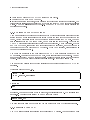
1
MPE JTAG Widget
Microprocessor Engineering Limited
v3.0
Copyright c 2004, 2005, 2006, 2007, 2008 Microprocessor Engineering Limited
Published by Microprocessor Engineering
MPE JTAG Widget
User manual
Manual revision 3.0
20 March 2009
Software
Software version v3.0
For technical support
Please contact your supplier
For further information
MicroProcessor Engineering Limited
133 Hill Lane
Southampton SO15 5AF
UK
Tel: +44 (0)23 8063 1441
Fax: +44 (0)23 8033 9691
e-mail: [email protected]
[email protected]
web: www.mpeforth.com
i
Table of Contents
1 Introduction . . . . . . . . . . . . . . . . . . . . . . . . . . . . . . . . . . . . . . . . . . . 1
1.1 What does it do? . . . . . . . . . . . . . . . . . . . . . . . . . . . . . . . . . . . . . . . . . . . . . . . . . . . . . . . . . . . . . . 1
1.2 About the MPE JTAG Widget . . . . . . . . . . . . . . . . . . . . . . . . . . . . . . . . . . . . . . . . . . . . . . . . . 1
1.2.1 Widget Hardware . . . . . . . . . . . . . . . . . . . . . . . . . . . . . . . . . . . . . . . . . . . . . . . . . . . . . . . . . 1
1.2.2 Widget Software . . . . . . . . . . . . . . . . . . . . . . . . . . . . . . . . . . . . . . . . . . . . . . . . . . . . . . . . . . 2
1.3 Getting started . . . . . . . . . . . . . . . . . . . . . . . . . . . . . . . . . . . . . . . . . . . . . . . . . . . . . . . . . . . . . . . . 2
1.3.1 Software installation . . . . . . . . . . . . . . . . . . . . . . . . . . . . . . . . . . . . . . . . . . . . . . . . . . . . . . 2
1.3.2 Talking to the JTAG Widget . . . . . . . . . . . . . . . . . . . . . . . . . . . . . . . . . . . . . . . . . . . . . . 3
1.3.3 Selecting your CPU . . . . . . . . . . . . . . . . . . . . . . . . . . . . . . . . . . . . . . . . . . . . . . . . . . . . . . . 3
1.3.4 Programming external Flash . . . . . . . . . . . . . . . . . . . . . . . . . . . . . . . . . . . . . . . . . . . . . . . 4
1.3.5 Optimising programing speed . . . . . . . . . . . . . . . . . . . . . . . . . . . . . . . . . . . . . . . . . . . . . . 4
1.3.6 Debugging ARM code . . . . . . . . . . . . . . . . . . . . . . . . . . . . . . . . . . . . . . . . . . . . . . . . . . . . . 5
1.3.7 Saving compiled code . . . . . . . . . . . . . . . . . . . . . . . . . . . . . . . . . . . . . . . . . . . . . . . . . . . . . 5
1.3.8 Using other terminal emulators . . . . . . . . . . . . . . . . . . . . . . . . . . . . . . . . . . . . . . . . . . . . 5
1.3.9 Using Linux and Macs . . . . . . . . . . . . . . . . . . . . . . . . . . . . . . . . . . . . . . . . . . . . . . . . . . . . . 5
1.4 About Forth . . . . . . . . . . . . . . . . . . . . . . . . . . . . . . . . . . . . . . . . . . . . . . . . . . . . . . . . . . . . . . . . . . 6
1.5 About the manual . . . . . . . . . . . . . . . . . . . . . . . . . . . . . . . . . . . . . . . . . . . . . . . . . . . . . . . . . . . . . 6
1.6 If disaster strikes . . . . . . . . . . . . . . . . . . . . . . . . . . . . . . . . . . . . . . . . . . . . . . . . . . . . . . . . . . . . . . 6
1.7 Installing software upgrades . . . . . . . . . . . . . . . . . . . . . . . . . . . . . . . . . . . . . . . . . . . . . . . . . . . . 6
1.8 Development Kit Tools . . . . . . . . . . . . . . . . . . . . . . . . . . . . . . . . . . . . . . . . . . . . . . . . . . . . . . . . 7
1.9 Technical support . . . . . . . . . . . . . . . . . . . . . . . . . . . . . . . . . . . . . . . . . . . . . . . . . . . . . . . . . . . . . 7
2 How Forth is documented . . . . . . . . . . . . . . . . . . . . . . . . . . . . . . . 9
2.1 Forth words . . . . . . . . . . . . . . . . . . . . . . . . . . . . . . . . . . . . . . . . . . . . . . . . . . . . . . . . . . . . . . . . . . . 9
2.2 Stack notation . . . . . . . . . . . . . . . . . . . . . . . . . . . . . . . . . . . . . . . . . . . . . . . . . . . . . . . . . . . . . . . 10
2.3 Input text . . . . . . . . . . . . . . . . . . . . . . . . . . . . . . . . . . . . . . . . . . . . . . . . . . . . . . . . . . . . . . . . . . . 11
2.4 Other markers . . . . . . . . . . . . . . . . . . . . . . . . . . . . . . . . . . . . . . . . . . . . . . . . . . . . . . . . . . . . . . . 12
3 First steps in debugging ARM code . . . . . . . . . . . . . . . . . . . . 13
3.1 Number bases . . . . . . . . . . . . . . . . . . . . . . . . . . . . . . . . . . . . . . . . . . . . . . . . . . . . . . . . . . . . . . . . 13
3.2 Connecting the target . . . . . . . . . . . . . . . . . . . . . . . . . . . . . . . . . . . . . . . . . . . . . . . . . . . . . . . . . 13
3.3 Initialising the JTAG connection . . . . . . . . . . . . . . . . . . . . . . . . . . . . . . . . . . . . . . . . . . . . . . 14
3.4 Stopping, Stepping and Restarting the CPU . . . . . . . . . . . . . . . . . . . . . . . . . . . . . . . . . . . . 14
3.5 Displaying memory . . . . . . . . . . . . . . . . . . . . . . . . . . . . . . . . . . . . . . . . . . . . . . . . . . . . . . . . . . . 15
3.6 Disassembling target code . . . . . . . . . . . . . . . . . . . . . . . . . . . . . . . . . . . . . . . . . . . . . . . . . . . . . 16
3.7 Assembling target code . . . . . . . . . . . . . . . . . . . . . . . . . . . . . . . . . . . . . . . . . . . . . . . . . . . . . . . 17
3.8 Target memory and peripherals . . . . . . . . . . . . . . . . . . . . . . . . . . . . . . . . . . . . . . . . . . . . . . . . 17
3.9 Flash programming . . . . . . . . . . . . . . . . . . . . . . . . . . . . . . . . . . . . . . . . . . . . . . . . . . . . . . . . . . . 18
3.10 Standard CPU support . . . . . . . . . . . . . . . . . . . . . . . . . . . . . . . . . . . . . . . . . . . . . . . . . . . . . . 18
4 Further debugging techniques . . . . . . . . . . . . . . . . . . . . . . . . . . 19
ii
MPE JTAG Widget
5 JTAG primitives . . . . . . . . . . . . . . . . . . . . . . . . . . . . . . . . . . . . . . 21
5.1 JTAG pin access . . . . . . . . . . . . . . . . . . . . . . . . . . . . . . . . . . . . . . . . . . . . . . . . . . . . . . . . . . . . . 21
5.2 Conguration . . . . . . . . . . . . . . . . . . . . . . . . . . . . . . . . . . . . . . . . . . . . . . . . . . . . . . . . . . . . . . . . 21
5.2.1 HwSel=NMIrevA . . . . . . . . . . . . . . . . . . . . . . . . . . . . . . . . . . . . . . . . . . . . . . . . . . . . . . . . 22
5.2.2 HwSel=MPErevA . . . . . . . . . . . . . . . . . . . . . . . . . . . . . . . . . . . . . . . . . . . . . . . . . . . . . . . . 22
5.3 JTAG primitives . . . . . . . . . . . . . . . . . . . . . . . . . . . . . . . . . . . . . . . . . . . . . . . . . . . . . . . . . . . . . 22
5.4 TAP state machine access . . . . . . . . . . . . . . . . . . . . . . . . . . . . . . . . . . . . . . . . . . . . . . . . . . . . . 24
5.5 Using multiple devices (daisy chain) . . . . . . . . . . . . . . . . . . . . . . . . . . . . . . . . . . . . . . . . . . . 26
5.6 Scan chain access . . . . . . . . . . . . . . . . . . . . . . . . . . . . . . . . . . . . . . . . . . . . . . . . . . . . . . . . . . . . . 26
5.7 Read and write IR and DR . . . . . . . . . . . . . . . . . . . . . . . . . . . . . . . . . . . . . . . . . . . . . . . . . . . . 28
5.8 Test code . . . . . . . . . . . . . . . . . . . . . . . . . . . . . . . . . . . . . . . . . . . . . . . . . . . . . . . . . . . . . . . . . . . . 28
6 ARM debug chains . . . . . . . . . . . . . . . . . . . . . . . . . . . . . . . . . . . . 29
6.1 Instruction register . . . . . . . . . . . . . . . . . . . . . . . . . . . . . . . . . . . . . . . . . . . . . . . . . . . . . . . . . . . 29
6.2 Test data registers . . . . . . . . . . . . . . . . . . . . . . . . . . . . . . . . . . . . . . . . . . . . . . . . . . . . . . . . . . . . 29
6.2.1 Instruction register . . . . . . . . . . . . . . . . . . . . . . . . . . . . . . . . . . . . . . . . . . . . . . . . . . . . . . . 29
6.2.2 Bypass . . . . . . . . . . . . . . . . . . . . . . . . . . . . . . . . . . . . . . . . . . . . . . . . . . . . . . . . . . . . . . . . . . 29
6.2.3 Core ID . . . . . . . . . . . . . . . . . . . . . . . . . . . . . . . . . . . . . . . . . . . . . . . . . . . . . . . . . . . . . . . . . 29
6.2.4 Scan chain select . . . . . . . . . . . . . . . . . . . . . . . . . . . . . . . . . . . . . . . . . . . . . . . . . . . . . . . . . 30
6.3 Debug Registers . . . . . . . . . . . . . . . . . . . . . . . . . . . . . . . . . . . . . . . . . . . . . . . . . . . . . . . . . . . . . . 32
6.3.1 DCC control (%00100, R/O) . . . . . . . . . . . . . . . . . . . . . . . . . . . . . . . . . . . . . . . . . . . . . . 32
6.3.2 Debug control (%00000, R/W) . . . . . . . . . . . . . . . . . . . . . . . . . . . . . . . . . . . . . . . . . . . . 33
6.3.3 Debug status (%00001, R/W) . . . . . . . . . . . . . . . . . . . . . . . . . . . . . . . . . . . . . . . . . . . . . 33
6.3.4 Debug register names . . . . . . . . . . . . . . . . . . . . . . . . . . . . . . . . . . . . . . . . . . . . . . . . . . . . 33
6.4 ARM JTAG instructions . . . . . . . . . . . . . . . . . . . . . . . . . . . . . . . . . . . . . . . . . . . . . . . . . . . . . . 34
6.5 Scan chain 1 . . . . . . . . . . . . . . . . . . . . . . . . . . . . . . . . . . . . . . . . . . . . . . . . . . . . . . . . . . . . . . . . . 34
6.6 Scan chain 2 . . . . . . . . . . . . . . . . . . . . . . . . . . . . . . . . . . . . . . . . . . . . . . . . . . . . . . . . . . . . . . . . . 35
6.7 High level debug support . . . . . . . . . . . . . . . . . . . . . . . . . . . . . . . . . . . . . . . . . . . . . . . . . . . . . . 36
6.8 Modifying registers . . . . . . . . . . . . . . . . . . . . . . . . . . . . . . . . . . . . . . . . . . . . . . . . . . . . . . . . . . . 38
6.9 CPU halt, restart and context . . . . . . . . . . . . . . . . . . . . . . . . . . . . . . . . . . . . . . . . . . . . . . . . . 38
6.10 CPU state display . . . . . . . . . . . . . . . . . . . . . . . . . . . . . . . . . . . . . . . . . . . . . . . . . . . . . . . . . . . 40
6.11 CPU Debug functions . . . . . . . . . . . . . . . . . . . . . . . . . . . . . . . . . . . . . . . . . . . . . . . . . . . . . . . 40
6.12 Breakpoints . . . . . . . . . . . . . . . . . . . . . . . . . . . . . . . . . . . . . . . . . . . . . . . . . . . . . . . . . . . . . . . . . 41
6.13 Target memory tools . . . . . . . . . . . . . . . . . . . . . . . . . . . . . . . . . . . . . . . . . . . . . . . . . . . . . . . . 42
6.14 Target CPU selection . . . . . . . . . . . . . . . . . . . . . . . . . . . . . . . . . . . . . . . . . . . . . . . . . . . . . . . . 42
6.15 Debug Comms Channel . . . . . . . . . . . . . . . . . . . . . . . . . . . . . . . . . . . . . . . . . . . . . . . . . . . . . . 43
6.15.1 Host Access . . . . . . . . . . . . . . . . . . . . . . . . . . . . . . . . . . . . . . . . . . . . . . . . . . . . . . . . . . . . 43
6.15.2 Target code . . . . . . . . . . . . . . . . . . . . . . . . . . . . . . . . . . . . . . . . . . . . . . . . . . . . . . . . . . . . 44
6.15.3 DCC console tools . . . . . . . . . . . . . . . . . . . . . . . . . . . . . . . . . . . . . . . . . . . . . . . . . . . . . . 45
7 Target memory words . . . . . . . . . . . . . . . . . . . . . . . . . . . . . . . . . 47
7.1 Big-endian host operations . . . . . . . . . . . . . . . . . . . . . . . . . . . . . . . . . . . . . . . . . . . . . . . . . . . . 47
7.2 Target memory and debug interface . . . . . . . . . . . . . . . . . . . . . . . . . . . . . . . . . . . . . . . . . . . . 47
7.3 Target memory tools . . . . . . . . . . . . . . . . . . . . . . . . . . . . . . . . . . . . . . . . . . . . . . . . . . . . . . . . . 50
7.4 Host memory . . . . . . . . . . . . . . . . . . . . . . . . . . . . . . . . . . . . . . . . . . . . . . . . . . . . . . . . . . . . . . . . 50
8 ARM disassembler . . . . . . . . . . . . . . . . . . . . . . . . . . . . . . . . . . . . 53
iii
9 ARM Assembler . . . . . . . . . . . . . . . . . . . . . . . . . . . . . . . . . . . . . . 55
9.1 Condition codes . . . . . . . . . . . . . . . . . . . . . . . . . . . . . . . . . . . . . . . . . . . . . . . . . . . . . . . . . . . . . . 55
9.2 Number bases . . . . . . . . . . . . . . . . . . . . . . . . . . . . . . . . . . . . . . . . . . . . . . . . . . . . . . . . . . . . . . . . 56
9.3 ARM instruction set . . . . . . . . . . . . . . . . . . . . . . . . . . . . . . . . . . . . . . . . . . . . . . . . . . . . . . . . . . 56
9.4 Thumb instruction set . . . . . . . . . . . . . . . . . . . . . . . . . . . . . . . . . . . . . . . . . . . . . . . . . . . . . . . . 57
9.5 Register naming . . . . . . . . . . . . . . . . . . . . . . . . . . . . . . . . . . . . . . . . . . . . . . . . . . . . . . . . . . . . . . 57
9.6 Immediate constants . . . . . . . . . . . . . . . . . . . . . . . . . . . . . . . . . . . . . . . . . . . . . . . . . . . . . . . . . . 58
9.7 Shift operations . . . . . . . . . . . . . . . . . . . . . . . . . . . . . . . . . . . . . . . . . . . . . . . . . . . . . . . . . . . . . . 58
9.8 Addressing modes . . . . . . . . . . . . . . . . . . . . . . . . . . . . . . . . . . . . . . . . . . . . . . . . . . . . . . . . . . . . 59
9.8.1 Pre-indexed addressing . . . . . . . . . . . . . . . . . . . . . . . . . . . . . . . . . . . . . . . . . . . . . . . . . . . 59
9.8.2 Post-indexed addressing . . . . . . . . . . . . . . . . . . . . . . . . . . . . . . . . . . . . . . . . . . . . . . . . . . 60
9.8.3 PC relative addressing . . . . . . . . . . . . . . . . . . . . . . . . . . . . . . . . . . . . . . . . . . . . . . . . . . . 60
9.8.4 Byte and half word addressing . . . . . . . . . . . . . . . . . . . . . . . . . . . . . . . . . . . . . . . . . . . . 60
9.8.5 Register lists . . . . . . . . . . . . . . . . . . . . . . . . . . . . . . . . . . . . . . . . . . . . . . . . . . . . . . . . . . . . 61
9.8.6 MVL and ADR . . . . . . . . . . . . . . . . . . . . . . . . . . . . . . . . . . . . . . . . . . . . . . . . . . . . . . . . . . 61
9.9 Control structures . . . . . . . . . . . . . . . . . . . . . . . . . . . . . . . . . . . . . . . . . . . . . . . . . . . . . . . . . . . . 62
9.10 Labels . . . . . . . . . . . . . . . . . . . . . . . . . . . . . . . . . . . . . . . . . . . . . . . . . . . . . . . . . . . . . . . . . . . . . . 62
9.11 Assembler error codes . . . . . . . . . . . . . . . . . . . . . . . . . . . . . . . . . . . . . . . . . . . . . . . . . . . . . . . 62
10 Flash programming harness . . . . . . . . . . . . . . . . . . . . . . . . . . . 65
10.1 Using supplied Flash drivers . . . . . . . . . . . . . . . . . . . . . . . . . . . . . . . . . . . . . . . . . . . . . . . . . 65
10.2 Writing your own Flash driver . . . . . . . . . . . . . . . . . . . . . . . . . . . . . . . . . . . . . . . . . . . . . . . . 65
10.2.1 Resident code . . . . . . . . . . . . . . . . . . . . . . . . . . . . . . . . . . . . . . . . . . . . . . . . . . . . . . . . . . 65
10.2.2 Driver le code . . . . . . . . . . . . . . . . . . . . . . . . . . . . . . . . . . . . . . . . . . . . . . . . . . . . . . . . . 66
11 AT49BV1614 Flash programming . . . . . . . . . . . . . . . . . . . . . 69
11.1 Conguration . . . . . . . . . . . . . . . . . . . . . . . . . . . . . . . . . . . . . . . . . . . . . . . . . . . . . . . . . . . . . . . 69
11.2 Flash Access routines . . . . . . . . . . . . . . . . . . . . . . . . . . . . . . . . . . . . . . . . . . . . . . . . . . . . . . . . 69
11.3 Code loaded into target RAM . . . . . . . . . . . . . . . . . . . . . . . . . . . . . . . . . . . . . . . . . . . . . . . . 70
11.4 Programing the device . . . . . . . . . . . . . . . . . . . . . . . . . . . . . . . . . . . . . . . . . . . . . . . . . . . . . . . 71
12 Atmel AT91SAM7xxx CPUs . . . . . . . . . . . . . . . . . . . . . . . . . . 73
12.1 Tools . . . . . . . . . . . . . . . . . . . . . . . . . . . . . . . . . . . . . . . . . . . . . . . . . . . . . . . . . . . . . . . . . . . . . . . 73
12.2 CPU denition . . . . . . . . . . . . . . . . . . . . . . . . . . . . . . . . . . . . . . . . . . . . . . . . . . . . . . . . . . . . . . 73
12.3 Register denitions and utilities . . . . . . . . . . . . . . . . . . . . . . . . . . . . . . . . . . . . . . . . . . . . . . 73
12.4 Board denition . . . . . . . . . . . . . . . . . . . . . . . . . . . . . . . . . . . . . . . . . . . . . . . . . . . . . . . . . . . . . 74
12.5 Hardware initialisation . . . . . . . . . . . . . . . . . . . . . . . . . . . . . . . . . . . . . . . . . . . . . . . . . . . . . . . 74
12.6 Flash programming . . . . . . . . . . . . . . . . . . . . . . . . . . . . . . . . . . . . . . . . . . . . . . . . . . . . . . . . . . 74
12.7 Code for target . . . . . . . . . . . . . . . . . . . . . . . . . . . . . . . . . . . . . . . . . . . . . . . . . . . . . . . . . . . . . . 75
12.8 Programming with Xmodem . . . . . . . . . . . . . . . . . . . . . . . . . . . . . . . . . . . . . . . . . . . . . . . . . 75
12.9 User instructions . . . . . . . . . . . . . . . . . . . . . . . . . . . . . . . . . . . . . . . . . . . . . . . . . . . . . . . . . . . . 76
13 RAM loader . . . . . . . . . . . . . . . . . . . . . . . . . . . . . . . . . . . . . . . . . 77
13.1 Code loaded into target RAM . . . . . . . . . . . . . . . . . . . . . . . . . . . . . . . . . . . . . . . . . . . . . . . . 77
13.1.1 Writing to RAM . . . . . . . . . . . . . . . . . . . . . . . . . . . . . . . . . . . . . . . . . . . . . . . . . . . . . . . . 77
13.1.2 Reading memory . . . . . . . . . . . . . . . . . . . . . . . . . . . . . . . . . . . . . . . . . . . . . . . . . . . . . . . . 78
13.2 Copying les to RAM and from memory . . . . . . . . . . . . . . . . . . . . . . . . . . . . . . . . . . . . . . 79
14 Further information . . . . . . . . . . . . . . . . . . . . . . . . . . . . . . . . . . 81
14.1 MPE courses . . . . . . . . . . . . . . . . . . . . . . . . . . . . . . . . . . . . . . . . . . . . . . . . . . . . . . . . . . . . . . . . 81
14.2 MPE consultancy . . . . . . . . . . . . . . . . . . . . . . . . . . . . . . . . . . . . . . . . . . . . . . . . . . . . . . . . . . . 81
14.3 Recommended reading . . . . . . . . . . . . . . . . . . . . . . . . . . . . . . . . . . . . . . . . . . . . . . . . . . . . . . . 82
iv
MPE JTAG Widget
Index . . . . . . . . . . . . . . . . . . . . . . . . . . . . . . . . . . . . . . . . . . . . . . . . . . . . 83
Chapter 1: Introduction
1
1 Introduction
This manual documents the MPE JTAG Widget software for ARM supplied with your JTAG
Widget. The underlying MPE ROM PowerForth software and the JTAG Widget hardware are
documented separately. PDF les in the DOCS folder are provided for the circuit diagram,
component layout and the default CPLD schematic.
1.1 What does it do?
The MPE JTAG Widget provides hardware and scripting software for debugging application
software and hardware.
The hardware has a USB connection to the host computer, and a JTAG interface using the
standard ARM 20 pin format to connect to the target device at data rates up to 8M bps.
The JTAG Widget has a 60MHz ARM CPU which you can control interactively through the
USB connection. On the host computer it is presented as another serial port so that you can
talk to the JTAG widget using a terminal emulator.
Additional I/O lines and a serial port can be connected to the target device and manipulated by
the JTAG widget, so allowing the JTAG widget to be used as a test stimulus generator. This is
extremely useful when narrowing down on faults that occur only very occasionally in the eld.
If you write test scripts as tasks, they do not interfere with the debugging facilities.
The JTAG software provides low and high level functions for JTAG access to ARM and other
CPUs. The software is based around the Forth programming language. You can write your own
scripts and programs which can be downloaded, compiled and saved onto the JTAG Widget
ready for your next session. At the lowest level, talking directly to the JTAG widget through a
terminal emulator is using a very powerful command-line debugger with scripting facilities.
Because the JTAG Widget uses simple communications systems, it is very easy to write programs, DLLs and shared libraries on the host computer that interface the JTAG Widget to third
party compilers, IDEs and high level debuggers.
1.2 About the MPE JTAG Widget
1.2.1 Widget Hardware
The JTAG Widget consists of several main blocks:
Power
All power is taken from the USB port. On board regulators generate 3.3 and 1.8
volt supplies.
CPU
Philips LPC2106 with 128k Flash and 64k RAM,
USB
FTDI FT245BM provides a fast comms link to the host PC, Mac, Linux or BSD
machine.
CPLD
Xilinx XC32/64 which is user programmable using the Xilinx WebPack software,
downloadable free from www.xilinx.com or on CD for a minimal cost. This is programmed to provide JTAG signal buering and level shifting.
2
MPE JTAG Widget
EEPROM
Atmel AT24C512 with 64kb storage. This can be used for program sorage and for
conguration.
The hardware is complemented by its default software. The MPE PowerForth system provided
with the JTAG widget contains a Forth compiler and interpreter, multitasker, timebase, comms
utilities, ash utilities and maintenance tools, as well as the JTAG software.
1.2.2 Widget Software
The JTAG Widget software provides all the routines required for JTAG access to ARM7 and
ARM9 CPUs. Because the software is based around a Forth interpreter, you can write your own
debugging scripts using the in-built commands, called words in Forth parlance.
The JTAG Widget is fast. An experiment using another device to program the Flash gave the
following results:
Wiggler
120 seconds
Widget
15 seconds
All our Flash and CPU drivers are supplied as source code. Using the supplied AIDE software
or a terminal emulator such as HyperTerm, you can download these drivers and compile them
on the JTAG Widget itself. You can write new Flash and CPU drivers yourself.
When you have programmed the Flash on your target board, you can use the JTAG Widget's
debugging facilities to test your application. As with the Flash and CPU drivers, you can keep
the code in a text le on your PC and compile it on the JTAG Widget. There is a spare
serial port and several I/O pins on the JTAG Widget are available on the JTAG IN and other
connectors. These can be used with your test code to provide signals to and from the board
under test.
The JTAG Widget uses the kernel software of the MPE USB Stamp. This is documented in the
le UsbStampCode.pdf.
All the executable software supplied on the CD is for Windows. See later for use on Linux, Mac
and other operating systems.
1.3 Getting started
1.3.1 Software installation
Run the installer on the CD. This will prompt you for a directory/folder into which it will install
all the issue les. It will also add a group called "MPE JTAG widget" on your Start menu.
This includes a short cut to AIDE (see later).
Install the FTDI Windows USB drivers from the CD if not already installed. If you are using a
Mac or a Linux host, drivers are available free of charge from:
www.ftdichip.com
The Windows driver makes a USB connection appear as a COM port. To install it:
Chapter 1: Introduction
3
Unzip the ZIP le in the USBDRIVERS folder to a new folder.
Connect the USB Stamp to a USB port.
If Windows asks you for a driver, point Windows to the folder you created in the rst step. The
driver will then install. In some cases you may have to run the "Add New Hardware/Programs"
wizard. The FTDI application note AN232-03.PDF in the USBDRIVERS folder describes the
process in more detail.
1.3.2 Talking to the JTAG Widget
AIDE is an Integrated Development Environment (IDE) that includes a simple editor for your
source code and a terminal emulator (PowerTerm) tuned for use with the PowerForth on the
board. Use the Properties button on the PowerTerm toolbar to select the COM port. The baud
rate is irrelevant for the USB stamp board, but we normally set it to 115200. Note that the
USB COM port is not available until the board has been connected. On the Properties -> Server
and XMODEM page, ensure that the Enable File Server box is checked, and that Xmodem is
congured for 1024 byte blocks and CRC checking. When AIDE is closed, these settings will
become the defaults next time.
The board communicates to the host using the USB COM port mechanism provided by the
FTDI drivers. Connect the board to a USB port, which also provides the power for it. You may
need to use a powered USB hub with some boards. Press the Connect button on the PowerTerm
toolbar. Reset the board using the little button on the side. PowerForth will sign on.
Commands typed directly into the Forth interpreter do not execute until the ENTER/CR key
is pressed.
Write a simple Forth word, e.g.
: hello
\ -cr cr ." Hello, world!" cr
;
hello
Execute it:
It will run. You can put the same code in a text le, conventionally with a .FTH extension such
as hello.fth. Compile the le (using AIDE and PowerTerm) with:
include hello.fth
The le will be compiled on the board and you can execute the word by typing HELLO again.
1.3.3 Selecting your CPU
The CPUs folder contains conguration code for several ARM devices. You can write new ones
4
MPE JTAG Widget
as required. Supported devices include the Philips LPC2xxx family and Atmel AT91 devices.
For families which include on-chip Flash, such as the Philips LPC2xxx, these les will include
the Flash programming code.
Before compiling the selected CPU le, edit it to select the required family member, crystal and
programming clock speeds. The following example shows how to set up and program a Philips
LPC2xxx device. You need not include the comments in what you type.
include CPUs\LPC2xxx.fth
2214 selectLPC
AllReset
initLPC
0 $3D000 ProgLPC
\
\
\
\
\
compile the code
select family device
reset JTAG and target
set up target
program whole device
If you want to program a batch of devices you can dene your own function.
: program \ -2214 selectLPC
AllReset initLPC
0 $3D000 ProgLPC
;
To save having to reload and retype this code, you can use turnkey to make it available at
powerup.
If you need help writing a CPU driver, contact MPE technical support. Please note that we will
need a hardware example for testing.
1.3.4 Programming external Flash
The Flash folder contains drivers for several Flash devices. You can modify these (or write your
own) for other devices.
After you have compiled the CPU conguration le, compile a suitable Flash driver and program
the device. Later chapters describe the facilities available for writing your own drivers. If you
need help writing a Flash driver, contact MPE technical support. Please note that we will need
a hardware example for testing.
1.3.5 Optimising programing speed
Programming speed is determined by the Flash, the Widget and the USB connection.
On AIDE's Powerterm Properties -> Server and XMODEM page, ensure that the Enable File
Server box is checked, and that Xmodem is congured for 1024 byte blocks and CRC checking.
When AIDE is closed, these settings will become the defaults next time.
Make sure that the Widget uses 1024 byte blocks by conguring AIDE typing:
Xmodem-1k
Chapter 1: Introduction
5
1.3.6 Debugging ARM code
The following chapters include an introduction to debugging applications with the JTAG Widget.
1.3.7 Saving compiled code
After you have congured and tested your conguration you can save it on the JTAG Widget
using the word Turnkey. Afterwards your code is always present when the JTAG Widget is
rebooted. This saves you having to recompile the conguration after each reboot, and is ideal
for production programming.
Save the compiled image:
0 turnkey
reboot
Either reset the board using the reset button or by typing:
The board will reboot, and your code will already be part of the system. You can check this by
typing words to see what functions are available.
empty reboot
You can clear out your previous work by typing EMPTY and rebooting:
1.3.8 Using other terminal emulators
AIDE and PowerTerm are designed for use with the JTAG Widget and include a source le
server. If you prefer, you can use other terminal emulators, but you will lose some facilities.
Set HyperTerm or another terminal emulator to 115200 baud, 8 data bits, no parity, 1 or 2 stop
bits. Select the relevant COM port for the JTAG Widget and reset the Widget, which will then
sign on. If all else fails, reash the system as described elswhere in this manual.
Please be aware that the standard Windows version of HyperTerm is very slow. A nuch faster
alternative is HyperTerminal Personal Edition from:
http://www.hilgraeve.com
1.3.9 Using Linux and Macs
The JTAG Widget's USB interface is through an FTDI device and a driver that simulates a
serial device. Any operating system that can provide these facilities can be used with the JTAG
Widget.
The software you will need is a terminal emulator with XModem le transfer utilities.
6
MPE JTAG Widget
1.4 About Forth
Forth is an interactive programming language widely used for embedded systems ranging from
bomb disposal machines to embedded web servers, seismic data loggers and safety critical medical
equipment. The DOCS folder on the CD includes the book "Programing Forth" in PDF format,
ProgramForth.pdf and a Forth primer, fprimer.pdf. Also included on the CD is an evaluation
version of MPE's VFX Forth for Windows. The latest version is available for free download
from
http://www.mpeforth.com
To run VFX Forth for Windows, send an email with your name, address and contact details to:
mailto://[email protected]
An installation key will then be provided.
1.5 About the manual
This manual is derived directly from the Forth source code used to generate the on-chip Forth.
The full source code is supplied with the MPE JTAG Widget Development Kit. Consequently
the documentation includes some words that do not have target entries in the on-chip Forth.
Some words and code routines are marked in the documentation as INTERNAL. These are
factors used by other words and do not have dictionary entries in the standalone Forth. They
are only accessible to users of the VFX Forth ARM Cross Compiler. This also applies to
denitions of the form:
n EQU <name>
PROC <name>
L: <name>
1.6 If disaster strikes
If you get the board into a bad state and it will not sign on, you may need to reload the
kernel program. Reprogram the board using the Philips ISP utility. The le to load is BINARIES\JTAGwidget.hex.
If the board still misbehaves, reload the ash with BINARIES\JTAGRECOVER.HEX and run
the board. This empties the serial EEPROM before signing on. Once you have seen the recovery
messages and PowerForth has signed on, you can use
reflash
to reload JTAGWIDGET.IMG and carry on in the normal way.
1.7 Installing software upgrades
JTAG Widget rmware upgrades are released several times per year. The rmware delivery will
be a binary image le, usually called JTAGwidget.img. The procedure to install the upgrade is
as follows.
Chapter 1: Introduction
7
1) Connect a terminal, e.g. AIDE, to the Widget in the usual way.
2) Type Reflash and follow the instructions. If you cannot complete the operation, connect
a serial port to to the JTAG Widget, convert the image le to a HEX le and use the Philips
ISP loader to program the Widget's internal Flash.
1.8 Development Kit Tools
If you have the development version of the JTAG Widget you will have the MPE Forth cross
compiler and all the JTAG Widget source code. Install the MPE Forth cross compiler and JTAG
Widget source code from the development CD.
Install the Philips ISP programmer software from the USBSTAMP\PhilipsIsp folder. This
requires a serial connection to the DB9 connector on the board. To use it, the link marked
BOOT on the board must be tted. To run all other software this link must be open. The
Philips ISP software is only needed if the on-board Forth software becomes corrupted.
N.B. If you have problems with the on-board Flash programming routines, check the LPC2106
bootloader version using the Philips ISP software or by typing
IAPBootVer .dword
which will give something of the form:
0000:xxyy
where xx is the major version number and yy is the minor version number. If this number is less
than 0000:0134 (hexadecimal) or 1.52 (decimal) you should update the bootloader using ISP
software version 2.2.0 or greater. These are available on the MPE CDs and from
www.semiconductors.philips.com
/files/products/standard/microcontrollers/utilities/
lpc2000_flash_utility.zip
lpc2000_bl_update.zip
Note that v1.52 is only for the LPC2104/5/6 and v1.63 is required for other parts such as the
LPC2119/2129. A PDF le in the update describes how to perform the update.
1.9 Technical support
Technical support is available from your supplier in rst instance, or from MicroProcessor Engineering.
8
MPE JTAG Widget
tel: +44 (0)23 8063 1441
fax: +44 (0)23 8033 9691
email: [email protected]
[email protected]
web: http://www.mpeforth.com
From North America, our telephone and fax numbers are:
011 44 23 8063 1441
011 44 23 8033 9691
901 313 4312 (access number to UK office)
Chapter 2: How Forth is documented
9
2 How Forth is documented
The Forth words in this manual are documented using a methodology based on that used for
the ANS standard document. As this is not a standards document but a user manual, we have
taken some liberties to make the text easier to read. We are not always as strict with our own
in-house rules as we should be. If you nd an error, have a complaint about the documentation
or suggestions for improvement, please send us an email or contact us in some other way.
When you browse the words in the Forth dictinary using WORDS or when reading source code
you may come across some words which are not documented. These words are undocumented
because they are words which are only used in passing as part of other words (factors), or
because these words may change or may not exist in later versions.
"Documentation is like sex: when it is good, it is very, very good; and when it is bad, it is better
than nothing." - Dick Brandon
2.1 Forth words
Word names in the text are capitalised or shown in a bold xed-point font, e.g. SWAP or SWAP.
Forth program examples are shown in a Courier font thus:
: NEW-WORD \ a b -- a b
OVER DROP
;
If you see a word of the form <name> it usually means that name is a placeholder for a name you
will provide.
The notation for the glossary entries in this manual have two major parts:
The denition line.
The description.
The denition line varies depending on the denition type. For instance - a normal Forth word
will look like:
: and
\ n1 n2 -- n3
6.1.0720
The left most column describes the word NAME and type (colon) the center column describes
the stack eect of the word and the far right column (if it exists) will specify either the ANS
language reference number or an MPE reference to distinguish between ANS standard and MPE
extension words.
The stack eect may be followed by an informal comment separated from the stack eect by a
';' character.
: and
\ x1 x2 -- x3 ; bitwise and
10
MPE JTAG Widget
This is a "quick reference" comment.
When you read MPE source code, you will see that most words are written in the style:
: foo
\ n1 n2 -- n3
\ *G This is the first glossary description line.
\ ** These are following glossary description lines.
...
;
Most MPE manuals are now written using the DocGen literate programming tool available and
documented with all VFX Forths for Windows, Linux and DOS. DocGen extracts documentation
lines (ones that start "\ *X ") from the source code and produces HTML or PDF manuals.
2.2 Stack notation
before -- after
where before means the stack parameters before execution and after means stack parameters
after execution. In this notation, the top of the stack is to the right. Words may also be shown
in context when appropriate. Unless otherwise noted, all stack notations describe the action of
the word at execution time. If it applies at compile time, the stack action is preceded by C: or
followed by (compiling)
An action on the return stack whill be shown
R: before -- after
Similarly, actions on the separate oat stack are marked by F: and on an exception stack by E:.
The denition of >R would have the stack notation
x -- ; R: -- x
Dening words such as VARIABLE usually indicate the stack action of the dening word
(VARIABLE) itself and the stack action of the child word. This is indicated by two stack actions separated by a ';' character, where the second action is that of the child word.
: VARIABLE
\ -- ; -- addr
In cases where confusion may occur, you may also see the following notation:
: VARIABLE
\ -- ; -- addr [child]
Unless otherwise stated all references to numbers apply to native signed integers. These will be
32 bits on 32 bit CPUs and 16 bits on embedded Forths for 8 and 16 bit CPUs. The implied
range of values is shown as {from..to}. Braces show the content of an address, particularly for
the contents of variables, e.g., BASE {2..72}.
The native size of an item on the Forth stack is referred to as a CELL. This is a 32 bit item on a
32 bit Forth, and on a byte-addressed CPU (the vast majority, most DSP chips excluded) this
is a four-byte item. On many CPUs, these must be stored in memory on a four-byte address
Chapter 2: How Forth is documented
11
boundary for hardware or performance reasons. On 16 bit systems this is a two-byte item, and
may also be aligned.
The following are the stack parameter abbreviations and types of numbers used in the documentation for 32 bit systems. On 16 bit systems the generic types will have a 16 bit range. These
abbreviations may be suxed with a digit to dierentiate multiple parameters of the same type.
Stack
Number
Range
Field
Abbreviation Type
(Decimal)
(Bits)
flag
boolean
0=false, nz=true 32
true
boolean
-1 (as a result) 32
false
boolean
0
32
char
character {0..255}
8
b
byte
{0..255}
8
w
word
{0..65535}
16
here word means a 16 bit item, not a Forth word
n
number
{-2,147,483,648
32
..2,147,483,647
x
32 bits
N/A
32
+n
+ve int
{0..2,147,483,647} 32
u
unsigned {0..4,294,967,295} 32
addr
address
{0..4,294,967,295} 32
a-addr
address
{0..4,294,967,295} 32
the address is aligned to a CELL boundary
c-addr
address
{0..4,294,967,295} 32
the address is aligned to a character boundary
32b
32 bits
not applicable
32
d
signed
{-9.2e18..9.2e18} 64
double
+d
positive {0..9.2e18}
64
double
ud
unsigned {0..1.8e19}
64
double
sys
0, 1, or more system dependent entries
char
character {0..255}
8
"text" text read from the input stream
Any other symbol refers to an arbitrary signed 32-bit integer unless otherwise noted. Because
of the use of two's complement arithmetic, the signed 32-bit number (n) -1 has the same bit
representation as the unsigned number (u) 4,294,967,295. Both of these numbers are within the
set of unspecied weighted numbers. On many occasions where the context is obvious, informal
names are used to make the documentation easier to understand.
2.3 Input text
Some Forth words read text from the input stream (e.g the keyboard or a le). That text is
read from the input stream is indicated by the identiers "<name>" or "text". This notation
refers to text from the input stream, not to values on the data stack.
Likewise, ccc indicates a sequence of arbitrary characters accepted from the input stream until
12
MPE JTAG Widget
the rst occurrence of the specied delimiter character. The delimiter is accepted from the input
stream, but it is not one of the characters ccc and is therefore not otherwise processed. This
notation refers to text from the input stream, not to values on the data stack.
Unless noted otherwise, the number of characters accepted may be from 0 to 255.
2.4 Other markers
The following markers may appear after a word's stack comment. These markers indicate certain
features and peculiarities of the word.
C
The word may only be used during compilation of a colon denition.
I
The word is immediate. It will be executed even during compilation, unless special
action is taken, e.g. by preceding it word with the word POSTPONE.
M
Aected by multi-tasking
U
A user variable.
Chapter 3: First steps in debugging ARM code
13
3 First steps in debugging ARM code
After you have connected to the JTAG Widget using a terminal emulator, you can start debugging an ARM target board and its code. The JTAG Widget is called the "host" and the board
you want to debug is called the "target". In turn, the PC or other USB master is the host for
the JTAG Widget.
3.1 Number bases
The number base in the Forth assembler can be indicated by the words BINARY DECIMAL and
HEX. In addition, numbers prexed by the `$', `#', `%' and `@' characters are treated as special
cases. These characters aect the number base for that number only. Note that the characters
`$' and `%' follow Motorola usage. Note that the `#' symbol attached to a number is not the
same as the # word that indicates immediate addressing.
Symbol
$
#
%
@
Base
hex
decimal
binary
octal
Example
$55AA
#1234
%1011001
@454
Hexadecimal numbers may also entered with a '0x' prex or an 'h' sux.
3.2 Connecting the target
The rst step is to connect the target to the JTAG Widget's "JTAG OUT" connector, J3 with
a ribbon cable. The J3 20 pin JTAG connector has the following pin out dened by ARM. Pin
1 is marked on the PCB and usually lines up with a stripe on the ribbon cable and a small mark
on the socket you plug in. See DUI0048F MICE2 2.pdf at www.arm.com for more details of the
20 pin interface. Input and Output in the table below are with respect to the JTAG Widget.
1
3
5
7
9
11
13
15
17
19
VTref/VCC
nTRST
TDI
TMS
TCK
RTCK
TDO
nSRST
DBGRQ
DBGACK
2
4
6
8
10
12
14
16
18
20
VCC
Gnd
Gnd
Gnd
Gnd
Gnd
Gnd
Gnd
Gnd
Gnd
Vtref from target, Vcc from target
open collector output
output pulled up/down on target
output pulled up on target
output pulled up on target
input
input
input/output pulled up on target
RFU
RFU
The JTAG Widget uses level shifters inside a CPLD to interface the target JTAG signals to the
CPU inside the host JTAG Widget. Thus it needs a very small amount of power from the target
board. The power should in the range 1.8 to 3.3 volts. The signal lines are 5 volt tolerant.
Most ARM development boards use the standard ARM 20-pin connector standard. If your
board uses a dierent format, you will have to obtain or make an adaptor.
14
MPE JTAG Widget
3.3 Initialising the JTAG connection
Commands for the JTAG Widget are case-insensitive.
The JTAG Widget initialises itself when it is rst powered up for a little-endian ARM 7. You
can conrm this by typing:
.target
If you need to repeat the initialisation of the JTAG Widget, type:
cold
If you have connected and powered up the target after the JTAG Widget has been powered up,
you may need to reset the target's JTAG system and maybe the CPU itself. Not all ARMs have
separate JTAG (TRST) and CPU (SRST) signals. Type:
AllReset
to reset the JTAG widget and the target CPU. The target should start executing whatever code
it contains.
3.4 Stopping, Stepping and Restarting the CPU
Many operations such as register inspection can only be performed in debug mode with the CPU
stopped. The command to stop the CPU is StopCpu ( -- ).
stopcpu
R0 = A000:001F 8200:E9FF 0200:3744 0000:0001
R4 = 0200:EE00 5000:0000 0000:0020 0000:0004
R8 = 0200:585C 0000:0006 0200:C0F0 0200:FF00
R12 = 0200:FEF0 0200:FDE0 0200:52AC 0200:5298
CPSR = A000:001F N_C__ ___ SYS
SPSR = A000:001F N_C__ ___ SYS
( 0200:5290 101400EB ...k ) bl # $200A2D8 ok
The status registers (CPSR and SPSR) are shown with the ag, I, F, and T bits displayed if
set. The mode bits are also decoded.
You can now single step the CPU using SingleStep ( -- ) or its synonym SS. Disassembly will
switch automatically between ARM and Thumb modes as required
Chapter 3: First steps in debugging ARM code
15
ss
R0 = A000:001F 8200:E9FF 0200:3744 0000:0001
R4 = 0200:EE00 5000:0000 0000:0020 0000:0004
R8 = 0200:585C 0000:0006 0200:C0F0 0200:FF00
R12 = 0200:FEF0 0200:FDE0 0200:5294 0200:A2E0
CPSR = A000:001F N_C__ ___ SYS
SPSR = A000:001F N_C__ ___ SYS
( 0200:A2D8 00000FE1 ...a ) mrs r0, cpsr ok
ss
R0 = A000:001F 8200:E9FF 0200:3744 0000:0001
R4 = 0200:EE00 5000:0000 0000:0020 0000:0004
R8 = 0200:585C 0000:0006 0200:C0F0 0200:FF00
R12 = 0200:FEF0 0200:FDE0 0200:5294 0200:A2E4
CPSR = A000:001F N_C__ ___ SYS
SPSR = A000:001F N_C__ ___ SYS
( 0200:A2DC 01002DE9 ..-i ) stmdb r13 ! { r0 } ok
ss
R0 = A000:001F 8200:E9FF 0200:3744 0000:0001
R4 = 0200:EE00 5000:0000 0000:0020 0000:0004
R8 = 0200:585C 0000:0006 0200:C0F0 0200:FF00
R12 = 0200:FEF0 0200:FDDC 0200:5294 0200:A2E8
CPSR = A000:001F N_C__ ___ SYS
SPSR = A000:001F N_C__ ___ SYS
( 0200:A2E0 C00080E3 @..c ) orr r0, r0, # $C0 ok
ss
R0 = A000:00DF 8200:E9FF 0200:3744 0000:0001
R4 = 0200:EE00 5000:0000 0000:0020 0000:0004
R8 = 0200:585C 0000:0006 0200:C0F0 0200:FF00
R12 = 0200:FEF0 0200:FDDC 0200:5294 0200:A2EC
CPSR = A000:001F N_C__ ___ SYS
SPSR = A000:001F N_C__ ___ SYS
( 0200:A2E4 00F021E1 .p!a ) msr cpsr_c, r0 ok
ss
R0 = A000:00DF 8200:E9FF 0200:3744 0000:0001
R4 = 0200:EE00 5000:0000 0000:0020 0000:0004
R8 = 0200:585C 0000:0006 0200:C0F0 0200:FF00
R12 = 0200:FEF0 0200:FDDC 0200:5294 0200:A2F0
CPSR = A000:00DF N_C__ IF_ SYS
SPSR = A000:00DF N_C__ IF_ SYS
( 0200:A2E8 0EF0A0E1 .p a ) mov pc, r14 ok
ss
R0 = A000:00DF 8200:E9FF 0200:3744 0000:0001
R4 = 0200:EE00 5000:0000 0000:0020 0000:0004
R8 = 0200:585C 0000:0006 0200:C0F0 0200:FF00
R12 = 0200:FEF0 0200:FDDC 0200:5294 0200:529C
CPSR = A000:00DF N_C__ IF_ SYS
SPSR = A000:00DF N_C__ IF_ SYS
( 0200:5294 04A02CE5 . ,e ) str r10, [ r12, # $-04 ] ! ok
When you are ready to resume normal operation, use RestartCPU ( -- ) to restart the CPU.
You can also use GoFrom ( addr -- ) to resume at a dierent address.
16
MPE JTAG Widget
3.5 Displaying memory
Target memory is displayed by the words BTdump, WTdump and LTdump. These three words all
require a starting address and a length (in bytes). They dier in that they display 8, 16 and 32
bit values respectively.
0 20 btdump
0000:0000 18 F0 9F E5 18 F0 9F
0000:0010 18 F0 9F E5 18 F0 9F
0 20 wtdump
0000:0000 F018 E59F F018 E59F
0000:0010 F018 E59F F018 E59F
ok
0 20 ltdump
0000:0000 E59F:F018 E59F:F018
0000:0010 E59F:F018 E59F:F018
ok
E5 18 F0 9F E5 18 F0 9F E5 .p.e.p.e.p.e.p.e
E5 20 FF 1F E5 20 FF 1F E5 .p.e.p.e ..e ..e
F018 E59F F018 E59F .p.e.p.e.p.e.p.e
FF20 E51F FF20 E51F .p.e.p.e ..e ..e
E59F:F018 E59F:F018 .p.e.p.e.p.e.p.e
E51F:FF20 E51F:FF20 .p.e.p.e ..e ..e
3.6 Disassembling target code
You can disassembler a range of memory using DisAsm/AL ( addr len -- .
You can select the instruction set using ARM-32 ( -- ) and Thumb-1 ( -- ).
0
(
(
(
(
(
(
(
(
(
(
(
(
(
(
(
(
$40 disasm/al
0000:0000 18F09FE5
0000:0004 18F09FE5
0000:0008 18F09FE5
0000:000C 18F09FE5
0000:0010 18F09FE5
0000:0014 18F09FE5
0000:0018 20FF1FE5
0000:001C 20FF1FE5
0000:0020 6C000000
0000:0024 00000000
0000:0028 00000000
0000:002C 00000000
0000:0030 00000000
0000:0034 00000000
0000:0038 00000000
0000:003C 00000000
.p.e
.p.e
.p.e
.p.e
.p.e
.p.e
..e
..e
l...
....
....
....
....
....
....
....
)
)
)
)
)
)
)
)
)
)
)
)
)
)
)
)
ldr
ldr
ldr
ldr
ldr
ldr
ldr
ldr
and
and
and
and
and
and
and
and
pc,
pc,
pc,
pc,
pc,
pc,
pc,
pc,
.eq
.eq
.eq
.eq
.eq
.eq
.eq
.eq
[ pc, #
[ pc, #
[ pc, #
[ pc, #
[ pc, #
[ pc, #
[ pc, #
[ pc, #
r0, r0,
r0, r0,
r0, r0,
r0, r0,
r0, r0,
r0, r0,
r0, r0,
r0, r0,
$18 ]
$18 ]
$18 ]
$18 ]
$18 ]
$18 ]
$-F20 ]
$-F20 ]
r12 rrx
r0
r0
r0
r0
r0
r0
r0 ok
(
(
(
(
(
(
(
(
@$20 = $6C
@$24 = $00
@$28 = $00
@$2C = $00
@$30 = $00
@$34 = $00
@$FFFFF100
@$FFFFF104
)
)
)
)
)
)
= $00 )
= $00 )
To disassemble a routine whose entry point is known, use DisAsm/F ( addr -- . Disassembly
will nish when either of the following instructions is encountered with no outstanding forward
branches up to a maximum of 512 bytes (128 ARM instructions).
Chapter 3: First steps in debugging ARM code
17
2003C78 disasm/f
( 0200:3C78 00402DE9 .@-i ) stmdb r13 ! { r14 }
( 0200:3C7C 0AFAFFEB .z.k ) bl # $20024AC
( 0200:3C80 30FAFFEB 0z.k ) bl # $2002548
( 0200:3C84 DAF9FFEB Zy.k ) bl # $20023F4
( 0200:3C88 00005AE3 ..Zc ) cmp r10, # $00
( 0200:3C8C 04A09CE4 . .d ) ldr r10, [ r12 ], # $04
...
( 0200:3D00 04A09CE5 . .e ) ldr r10, [ r12, # $04 ]
( 0200:3D04 08C08CE2 [email protected] ) add r12, r12, # $08
( 0200:3D08 E5FFFFEA e..j ) b # $2003CA4
( 0200:3D0C 04A09CE5 . .e ) ldr r10, [ r12, # $04 ]
( 0200:3D10 08C08CE2 [email protected] ) add r12, r12, # $08
( 0200:3D14 0080BDE8 ..=h ) ldmia r13 ! { pc }
A0 bytes, 28 instructions. ok
3.7 Assembling target code
To select the instruction set use ARM-32 ( -- ) or Thumb-1 ( -- ).
To dene a target piece of assembler use:
<address> ORG(T)
ASSEMBLER
<ARM assembler code>
END-CODE
Use of the target assembler is covered in a separate chapter.
3.8 Target memory and peripherals
Individual memory locations can be read and written. See the chapter on "Target memory
words" for more detail. Because I/O is memory mapped on ARM systems, these words can be
used to read and write peripheral registers.
: b@c(t)
\ addr -- b
: w@c(t)
\ addr -- w
: l@c(t)
\ addr -- l
: x@c(t)
\ addr -- xl xh
: b!c(t)
\ b addr --
: w!c(t)
\ w addr --
: l!c(t)
\ l addr --
8 bit byte fetch.
16 bit halfword fetch.
32 bit word fetch.
64 bit word fetch.
8 bit byte store.
16 bit halfword store.
18
MPE JTAG Widget
32 bit word store.
: x!c(t)
64 bit word store.
\ xl xh addr --
3.9 Flash programming
The Flash folder contains drivers for supported Flash devices. All drivers are supplied as source
code which can be compiled by the JTAG Widget. A later chapter describes:
Using supplied drivers
Writing your own drivers
3.10 Standard CPU support
As with Flash drivers, initialisation code for dierent CPUs is supplied as source code which
can be compiled by the JTAG Widget. These les are in the CPUs folder. See the Flash
Programming chapter for more details.
Chapter 4: Further debugging techniques
4 Further debugging techniques
In preparation
19
20
MPE JTAG Widget
Chapter 5: JTAG primitives
21
5 JTAG primitives
The 20 pin JTAG connector has the following pin out dened by ARM. See
DUI0048F MICE2 2.pdf at www.arm.com.
1
3
5
7
9
11
13
15
17
19
VTref/VCC
nTRST
TDI
TMS
TCK
RTCK
TDO
nSRST
DBGRQ
DBGACK
2
4
6
8
10
12
14
16
18
20
VCC
Gnd
Gnd
Gnd
Gnd
Gnd
Gnd
Gnd
Gnd
Gnd
Vtref from target, Vcc from target
open collector output
output pulled up/down on target
output pulled up on target
output pulled up on target
input
input
input/output pulled up on target
RFU
RFU
5.1 JTAG pin access
The target TAP controller uses the JTAG signals as follows:
TCK
clock input (output by us)
TMS
mode input (output by us) sampled on the RISING edge of TCK, and expected
to change on the falling edge of TCK. TMS should be high at the rising edge of
nTRST.
TDI
data input (output by us) sampled on the RISING edge of TCK, and expected to
change on the falling edge of TCK.
TDO
data output (input by us) changes on the FALLING edge of TCK, so we sample it
just before the rising edge of TCK.
nTRST
Active low JTAG reset signal. nTRST can be held low to disable JTAG in many
systems. It must be high to use JTAG. TMS should high at the rising edge of
nTRST. Asynchronous - independent of TCK.
The GPIO pin registers are:
IOPIN
IOSET
IOCLR
IODIR
r/o
r/w
w/o
r/w
read pin state
write 1 to set, read o/p state
write 1 to clear
0=i/p, 1=o/p
5.2 Conguration
These equates select the denitions for the NMI and MPE RevA and RevB boards. The TCK
active state can also be selected.
MPErevA equ hwSel
Select current hardware.
1 equ TCKactiveHi?
\ -- flag
If set true, TCK is active high, and idles low.
22
MPE JTAG Widget
5.2.1 HwSel=NMIrevA
The connections provided by the NMI ARM serial proto stamp are:
Pin
1 VCC
3 nTRST
5 TDI
7 TMS
9 TCK
11 RTCK
13 TDO
15 nSRST
17 DBGRQ
19 DBGACK
P0.31
P0.30
P0.29
P0.28
P0.27
P0.26
P0.22
P0.2
P0.3
Pin
2 VCC
4 Gnd
6 Gnd
8 Gnd
10 Gnd
12 Gnd
14 Gnd
16 Gnd
18 Gnd
20 Gnd
GPIO alternate functions
3v3 from LK13 or target
o/p
TDO
res
res
o/p
TDI
res
res
o/p
TCK
res
res
o/p
TMS
res
res
i/p
TRST
res
res
i/p
res
res
res
o/p
res
res
res
RFU SCL
Cap0.0 res
RFU SDA
Mat0.0 res
5.2.2 HwSel=MPErevA
The connections provided by the MPE ARM USB proto stamp are:
Pin
1 VCC
3 nTRST
5 TDI
7 TMS
9 TCK
11 RTCK
13 TDO
15 nSRST
17 DBGRQ
19 DBGACK
P0.26
P0.25
P0.22
P0.23
P0.24
P0.27
P0.28
P0.29
P0.30
P0.31
Pin
2 VCC
4 Gnd
6 Gnd
8 Gnd
10 Gnd
12 Gnd
14 Gnd
16 Gnd
18 Gnd
20 Gnd
GPIO alternate functions
from target
o/p
res
res
res
o/p
res
res
res
o/p
res
res
res
o/p
res
res
res
i/p
res
res
res
i/p
TRST
res
res
o/p
TMS
res
res
RFU TCK
res
res
RFU TDI
res
res
RFU
TDO
res
res
5.3 JTAG primitives
#10 value /qbit \ -- n
Quarter bit delay value for software loops.
: SetJTAGspeed \ kHz --
Set the quarter bit delay to achieve the specied JTAG clock speed in Khz
create ^GPIO _GPIO ,
Pointer to GPIO block
\ -- addr
: nTRSTlo
( -- ) nTRST ^GPIO @ IOCLR + ! ;
: nTRSThi
( -- ) nTRST ^GPIO @ IOSET + ! ;
: TDIlo
( -- ) TDI ^GPIO @ IOCLR + ! ;
: TDIhi
( -- ) TDI ^GPIO @ IOSET + ! ;
Set TRST low
Set TRST high
Set TDI low
Chapter 5: JTAG primitives
23
Set TDI high
: TMSlo
( -- ) TMS ^GPIO @ IOCLR + ! ;
: TMShi
( -- ) TMS ^GPIO @ IOSET + ! ;
: TCKlo
( -- ) TCK ^GPIO @ IOCLR + ! ;
: TCKhi
( -- ) TCK ^GPIO @ IOSET + ! ;
: nSRSTlo
( -- ) nSRST ^GPIO @ IOCLR + ! ;
: nSRSThi
( -- ) nSRST ^GPIO @ IOSET + ! ;
Set TMS low
Set TMS high
Set TCK low
Set TCK high
Set nSRST low
Set nSRST high
: RTCK@ ( -- 0/1 ) ^GPIO @ IOPIN + @ RTCK and #RTCK rshift ;
Read state of RTCK.
: TDO@ ( -- 0/1 ) ^GPIO @ IOPIN + @ TDO and #TDO rshift ;
Read state of TDO.
: SRST@ ( -- 0/1 ) ^GPIO @ IOPIN + @ nSRST and #SRST rshift ;
Read state of SRST.
: InitJTAG
\ --
code TCKpulse
\ --
code TDOread
\ -- 0/1
code TDIwrite
\ x --
code TDIOxchg
\ x1 mask -- x2
code TCKpulse
\ --
code TDOread
\ -- 0/1
code TDIwrite
\ x --
Initialise JTAG system.
Pulse TCK high then low
Read TDO after the rising edge of TCK. TDO changes on the falling edge of TCK, and so the
rst bit of a transfer is available after any state change. TDO is sampled on the rising edge of
TCK. TDO is written back to TDI to preserve the register when the update is performed.
if x is non-zero, write 1 to TDI, otherwise write 0. TDI is written out on/after the falling edge
of TCK, and is sampled by the target on the rising edge of TCK.
if x1.mask is non-zero, write 1 to TDI, otherwise write 0. TDI is written out on/after the falling
edge of TCK, and is sampled by the target on the rising edge of TCK. Replace the bit dened
by mask with the value read from TDO.
Pulse TCK low then high
Read TDO after the rising edge of TCK. TDO changes on the falling edge of TCK, and so the
rst bit of a transfer is available after any state change. TDO is sampled on the rising edge of
TCK. TDO is written back to TDI to preserve the register when the update is performed.
if x is non-zero, write 1 to TDI, otherwise write 0. TDI is written out on/after the falling edge
of TCK, and is sampled by the target on the rising edge of TCK.
24
MPE JTAG Widget
code TDIOxchg
\ x1 mask -- x2
: CkTMShi
\ --
: CkTMSlo
\ --
if x1.mask is non-zero, write 1 to TDI, otherwise write 0. TDI is written out on/after the falling
edge of TCK, and is sampled by the target on the rising edge of TCK. Replace the bit dened
by mask with the value read from TDO.
Set TMS high and pulse TCK
Set TMS low and pulse TCK
5.4 TAP state machine access
This section deals with moving the JTAG state machine between its various states. State
numbers are as dened in the JTAG specication.
$0F equ jsTLR
\ -- n
$0E equ jsCIR
\ -- n
$0D equ jsUIR
\ -- n
$0C equ jsRTI
\ -- n
$0B equ jsPIR
\ -- n
Test Logic Reset
Capture IR
Update IR
Run Test Idle
Pause IR
$0A equ jsShIR \ -- n
Shift IR
$09 equ jsE1IR \ -- n
Exit1 IR
$08 equ jsE2IR \ -- n
Exit2 IR
$07 equ jsSelDRS
Select DR scan
$06 equ jsCDR
\ -- n
$05 equ jsUDR
\ -- n
Capture DR
Update DR
$04 equ jsSelIRS
Select IR Scan
$03 equ jsPDR
Pause DR
\ -- n
$02 equ jsShDR \ -- n
Shift DR
$01 equ jsE1DR \ -- n
Exit1 DR
\ -- n
\ -- n
Chapter 5: JTAG primitives
25
$00 equ jsE2DR \ -- n
Exit2 DR
variable CurrSC \ -- addr
Holds the current scan chain number.
variable JTAGstate
\ -- addr
Holds the current JTAG state,
: .JTAGstate
\ --
Display the name of a JTAG TAP state.
: ShowJTAGstate \ --
Display the name of the current JTAG TAP state.
: goRTI
\ --
Use the TMS and TCK signals to leave the JTAG TAP in the RUN-TEST/IDLE state by
clocking TMS high ve times, and then TMS low once. This word is only used as a recovery
mechanism to get the JTAG system into a known state.
: UxR>RTI
\ --
Take the TAP from UDR or UIR to Run-Test/Idle.
: TargetReset
\ --
Reset the target with a 10 ms low pulse on SRST. Note that on many ARM systems, this will
also reset the JTAG system.
: JTAGreset
\ --
Use the nTRST signal to reset the JTAG logic (10 ms pulse), and leave JTAG in RUNTEST/IDLE state.
: AllReset
\ --
Resets the target and the JTAG system, leaving JTAG in Run-Test/Idle. Run at power up.
: UxRgoto
\ state --
Move the JTAG state machine from UxR to one of SelDRS, SelIRS, TLR and RTI.
: RTIgoto
\ state --
Move the JTAG state machine from RTI to one of SelDRS, SelIRS, TLR and RTI.
: SelDRSgoto
\ state --
Move the JTAG state machine from SelDRS to one of SelDRS, SelIRS, TLR and RTI.
: JTAGgoto
\ state --
Move the JTAG state machine to the selected state. This is principally used to get from UpdatexR to the next required state. It also handles going from Test-Logic-Reset and Run/Test-Idle. If
the current state is not the required state, an Update-xR, Test-Logic-Reset or Run/Test-IDLE
an error message is issued by a -2 THROW.
: gotoSDR
\ --
Move to Select-DR state
: gotoSIR
\ --
Move to Select-IR state
26
MPE JTAG Widget
5.5 Using multiple devices (daisy chain)
Multiple JTAG devices can be placed in one JTAG chain. To select a specic device, the JTAG
instruction register is written with a sequence that selects one device but puts all other device
in BYPASS (all bits 1). After this, the data register for other devices will be 1 bit wide.
Instruction register, where the selected device has an instruction register that is n bits wide:
TDI
w bits x bits ... n bits ... y bits z bits
TDO
Data register, where the selected device has an data register that is m bits wide:
TDI
1 bit 1 bit ... m bits ... 1 bit 1 bit
TDO
In order to use daisy chained devices, we need to know:
The number of JTAG units at TDI before the unit we want to talk to,
The total number of instruction register bits at TDI before the unit we want to talk to,
The number of JTAG units after the unit we want to talk to before TDO,
The total number of JTAG units after the unit we want to talk to before TDO.
0 value #IRpreTDI
\ -- n
0 value #IRpostTDO
\ -- n
0 value #DRpreTDI
\ -- n
0 value #DRpostTDO
\ -- n
The number of instruction register bits before the TDI signal of the device we want to talk to.
The number of instruction register bits after the TDO signal of the device we want to talk to.
The number of devices (data register bits) before the TDI signal of the device we want to talk
to.
The number of devices (data register bits) after the TDO signal of the device we want to talk
to.
5.6 Scan chain access
This section provides routines to read and write the scan chains.
0 value MSatTDO?
\ -- n
If this value is non-zero, bits are read/written most signicant rst (msb nearest to TDO),
otherwise they are read/written least signicant rst (lsb nearest to TDO)
: MSatTDO
( -- ) 1 to MSatTDO? ;
: LSatTDO
( -- ) 0 to MSatTDO? ;
Set the read/write direction to most signicant bit rst.
Set the read/write direction to least signicant bit rst.
Chapter 5: JTAG primitives
: #TCKpulses
\ n --
: [gR
\ -- ; used to be called [xR
: [IR
\ --
: [DR
\ --
: xRin
\ n -- x
: FinalxR
\ u -- ; u non-zero
: gRin]
\ n #after -- x
: DRin]
\ n -- x
: IRin]
\ n -- x
: xRxchg
\ x1 n -- x2
: gRxchg]
\ x1 n #after -- x2
: DRxchg]
\ x1 n -- x2
: IRxchg]
\ x1 n -- x2
: xRout
\ x n --
: gRout]
\ x n #after --
: DRout]
\ x n --
: IRout]
\ x n --
27
Outputs n TCK pulses. TDI is unchanged and TDO is ignored.
Start an IR or DR transfer from Select-xR, going to Shift-xR
Start an IR transfer from Select-IR, going to Shift-IR and then shifting out any bits destined
for after TDO.
Start an DR transfer from Select-DR, going to Shift-DR and then shifting out any bits destined
for after TDO.
Read n bits as x, staying in Shift-xR state. This word must not be used for the last bit.
Clock the IR/DR by u bits, where u must not be zero. TDI is set to one and the last clock is
issued with TMS=1 to go to the JTAG Exit1-xR state.
Read the last n bits as x, followed by any BYPASS/unused bits, ending in Update-xR state.
Read the last n bits as x, followed by any unused bits, ending in Update-DR state.
Read the last n bits as x, followed by any BYPASS bits, ending in Update-IR state.
Read/write n bits out from x1 and in to x2, staying in Shift-xR state. This word must not be
used for the last bit.
Read/write n bits out from x1 and in to x2, followed by
in Update-xR state.
#after BYPASS/unused bits, ending
Read/write n bits out from x1 and in to x2, followed by any unused bits, ending in Update-DR
state.
Read/write n bits out from x1 and in to x2, followed by any unused bits, ending in Update-IR
state.
Write n bits from x, staying in Shift-xR state. This word must not be used for the last bit.
Write n bits from x, followed by #after BYPASS/unused bits, ending in Update-xR state.
Write n bits from x, followed by any unused bits, ending in Update-DR state.
Write n bits from x, followed by any BYPASS bits, ending in Update-IR state.
28
MPE JTAG Widget
5.7 Read and write IR and DR
This section provides words to read and write the JTAG Instruction and Data registers.
: DRread
\ n -- x
: IRread
\ n -- x
: DRwrite
\ x n --
: IRwrite
\ x n --
n bits (32 max) are read from TDO and returned as x. The TAP is moved to Select-DR-Scan
before starting, and is left in Update-DR.
n bits (32 max) are read from TDO and returned as x. The TAP is moved to Select-IR-Scan
before starting, and is left in Update-DR.
Write the n (32 max) least signicant bits of x to the data register. The TAP is moved to
Select-DR-Scan before starting, and is left in Update-DR.
Write the n (32 max) least signicant bits of x to the instruction register. The TAP is moved
to Select-IR-Scan before starting, and is left in Update-DR.
5.8 Test code
This code is only compiled if the equate DIAGS? is non-zero at compile time.
Chapter 6: ARM debug chains
29
6 ARM debug chains
The ARM7 specic data was extracted from ARM manuals DAI0028, DAI0038B and DDI0029G.
The ARM9 specic data was extracted from ARM manuals DDI 0145A and DDI 0151C
6.1 Instruction register
This is 4 bits wide for ARM7/9 and 5 or 7 bits wide for XScale, with the least signicant bit at
TDO. Select LSatTDO before shifting into the IR.
4 value /IR
\ -- n
Number of bits in the instruction register.
%0000 const cmdEXTEST
Connects selected scan chain between TDI and TDO ready for DR access.
%0010 const cmdSCAN_N
After issuing SCAN N, a four bit scan chain number is put into the DR, which always returns
%10000 (LSatTDO). The selected scan chain number is placed between TDI and TDO.
%0011 const cmdSAMPLE
%0011 const cmdPRELOAD
Production test only.
%0100 const cmdRESTART
Causes the core to restart, selects BYPASS mode, and exits debug mode when RUN-TEST/IDLE
is reached.
%0101 const cmdCLAMP
Selects BYPASS, and prevents UPDATE-DR aecting the data register. For scan chain 0 only.
6.2 Test data registers
6.2.1 Instruction register
4 bits, LSatTDO.
6.2.2 Bypass
A one bit register which always reads 0 and has no eect on update.
6.2.3 Core ID
32 bits, LSatTDO.
TDI
Bits 31..28
Bits 27..12
Bits 11..1
Bit 0
TDO
version
part number
manufacturer ID
always 1
30
MPE JTAG Widget
Scan chain 0
Scan chain 0 accesses the ARM7TDMI core periphery. It is specied by ARM manual DDI0029G
as 105 bits:
TDI
Data bus 0..31 - D31 scanned out first
control signals
Address 31..0 - A0 scanned out first
TDO
MSatTDO
LSatTDO
Scan chain 1
A 33 bit register.
TDI
Data bus 0..31 - D31 scanned out first
BREAKPT bit
- first to appear
TDO
MSatTDO
Scan chain 2
This 38 bit register/chain accesses the Embedded ICE registers. You must set INTEST after
SCAN N(2).
TDI
1 bit R/W
Addr 4..0
Data 31..0
TDO
- 0=read, 1=write
- register select, LSatTDO
- data, LSatTDO
6.2.4 Scan chain select
ARM7
4 bits, LSatTDO. Always reads %1000.
ARM9
5 bits, LSatTDO. Always reads %10000.
4 value /scan
\ -- n
Number of bits in the scan chain select register.
Scan chain 0
Scan chain 0 accesses the ARM9TDMI core periphery.
DDI 0145A as 184 bits:
It is specied by ARM manual
Chapter 6: ARM debug chains
31
TDI
Data bus 0..31 - D31 scanned out first
control signals
Address 31..0 - A0 scanned out first
TDO
MSatTDO
LSatTDO
Scan chain 1
A 67 bit register, 32 value, 32 instruction, 3 control
TDI
Instruction data 31..0, bit 31 first
SYSSPEED bit
BREAKPT bit
DDEN bit
Data bus 0..31 - D0 scanned out first
TDO
MSatTDO
LSatTDO
Scan chain 2
This 38 bit register/chain accesses the Embedded ICE registers. You must set INTEST after
SCAN N(2).
TDI
1 bit R/W
Addr 4..0
Data 31..0
TDO
- 0=read, 1=write
- register select, LSatTDO
- data, LSatTDO
Scan chain 3
Implementation specic external boundary scan.
Scan chain 4
Provides access to PA TAG RAM, 49 bits, bit 0 at TDO
TDI
48
47
46
45..40
39..33
32
31..0
TDO
-
PA TAG sel TCK
RAM enable
Odd not Even
Scan index
Scan reg
PA TAG sync TCK
WBPA
ARM9 - Scan chain 15
For CP15 access, 40 bits, bit 0 at TDO
32
MPE JTAG Widget
TDI
1 bit R/W
addr 5..0
data 31..0
1 bit mode
TDO
- 0=read, 1=write
- register select, LSatTDO
- instruction or data, LSatTDO
0=interpreted, 1=physical
ARM966 - Scan chain 15
For CP15 access, 30 bits, bit 0 at TDO
TDI
1 bit R/W
addr 5..0
data 31..0
TDO
- 0=read, 1=write
- register select, LSatTDO
- instruction or data, LSatTDO
6.3 Debug Registers
Scan chain 2 is a 38 bit register/chain which accesses the Embedded ICE registers for ARM7
and ARM9s. You must set INTEST after SCAN N(2).
TDI
1 bit R/W
Addr 4..0
Data 31..0
TDO
- 0=read, 1=write
- register select, LSatTDO
- data, LSatTDO
Data is read/written at update (NOT capture) according to the register address and the R/W
bit.
Address Width Register
%00000
4 Debug control
%00001
5 Debug status
%00010
8 Vector catch control (ARM9)
%00100
6 Debug comms channel (DCC) control
%00101
32 Debug comms channel (DCC) data
%01000
32 Watchpoint 0 address value
%01001
32
addr mask: 0=compare,
%01010
32
data value
%01011
32
data mask: 0=compare,
%01100
9
control value
%01101
8
control mask
%10000
32 Watchpoint 1 address value
%10001
32
addr mask: 0=compare,
%10010
32
data value
%10011
32
data mask: 0=compare,
%10100
9
control value
%10101
8
control mask
1=ignore
1=ignore
1=ignore
1=ignore
Chapter 6: ARM debug chains
33
6.3.1
DCC control (%00100, R/O)
Bits 31..26
27..2
1
0
Embedded ICE version
RFU
W=0=no data from CPU, W=1=data from CPU
R=0=can send to CPU, R=1=last not read
The CPU uses the following instructions to access the DCC in coprocessor 14.
MRC #14 0 Rd CR0 CR0 0
MCR #14 0 Rn CR1 CR0 0
MRC #14 0 Rn CR1 CR0 0
6.3.2
Debug control (%00000, R/W)
Bit 2
Bit 1
Bit 0
6.3.3
Bit
Bit
Bit
Bit
Bit
\ read DCC control register
\ write DCC data (send to CPU)
\ read DCC data (recv from CPU)
INTDIS 1=disable IRQ and FIQ
DBGRQ 1=force debug request
DBGACK 1=force debug ACK
Debug status (%00001, R/W)
4
3
2
1
0
TBIT
cogent
IFEN
DBGRQ
DBGACK
0=ARM, 1=Thumb
Debug memory access completed
Core IFEN signal
status
status
6.3.4 Debug register names
%00000 constant dbrControl
\ -- n
$00001 constant dbrStatus
\ -- n
%00100 constant dbrDCCcontrol
\ -- n
%00101 constant dbrDCCdata
\ -- n
%01000 constant dbrW0Aval
\ -- n
%01001 constant dbrW0Amask
\ -- n
%01010 constant dbrW0Dval
\ -- n
%01011 constant dbrW0Dmask
\ -- n
Debug Control
Debug Status
DCC control
DCC data
Watchpoint 0 address value
Watchpoint 0 address mask
Watchpoint 0 data value
Watchpoint 0 data mask
34
MPE JTAG Widget
%01100 constant dbrW0Cval
\ -- n
%01101 constant dbrW0Cmask
\ -- n
%10000 constant dbrW1Aval
\ -- n
%10001 constant dbrW1Amask
\ -- n
%10010 constant dbrW1Dval
\ -- n
%10011 constant dbrW1Dmask
\ -- n
%10100 constant dbrW1Cval
\ -- n
%10101 constant dbrW1Cmask
\ -- n
Watchpoint 0 control value
Watchpoint 0 address value
Watchpoint 1 address value
Watchpoint 1 address mask
Watchpoint 1 data value
Watchpoint 1 data mask
Watchpoint 1 control value
Watchpoint 1 address value
Note that the mask registers are XNOR. Matches occur when mask XNOR value==data = 1
for all bits. Setting a mask bit to 0 means that the bit ALWAYS matches.
mask | value | data | match
0
x
x
1
1
0
0
1
1
0
1
0
1
1
0
0
1
1
1
1
6.4 ARM JTAG instructions
: SetIDCODE
\ --
: SetINTEST
\ --
: SetChain
\ n --
: ReadChipID
\ -- id
Output the IDCODE instruction
Output the INTEST instruction
Select scan chain n (0..15) and issue INTEST. If the current chain is n, no action is taken. Set
CURRSC to -1 beforehand to force the action.
Read the chip ID from scan chain 2.
6.5 Scan chain 1
This chain is used to force instructions and data into the instruction pipeline at debug speed,
aor to run instructions (memory access or branch) at system speed.
ARM7: A 33 bit register.
Chapter 6: ARM debug chains
35
TDI
Data bus 0..31 - D31 scanned out first
BREAKPT bit
- first to appear
TDO
MSatTDO
ARM9: A 67 bit register, 32 value, 32 instruction, 3 control
TDI
Instruction data 31..0, bit 31 first
SYSSPEED bit
BREAKPT bit
DDEN bit
Data bus 0..31 - D0 scanned out first
TDO
: StepARM7
MSatTDO
LSatTDO
\ opcode mode -- data
Perform a single ARM7 instruction at debug (mode=0) or system (mode=-1) speed, returning
the data read back.
: StepARM9
\ opcode mode data -- data'
Perform a single ARM9 instruction at debug (mode=0) or system (mode=-1) speed, returning
the data read back.
: StepCore
\ opcode mode -- data
Perform a single instruction at debug (mode=0) or system (mode=-1) speed, returning the data
read back. The TAP is left in RTI state.
: SystemStep
\ opcode --
Perform a single instruction at the current speed. Whether previous, current or next instruction
runs at system speed depends on the core type. The TAP is left in RTI state.
: DebugStep
\ opcode --
Perform a single instruction at debug speed. The TAP is left in RTI state.
: DebugStepRead \ opcode -- data
Perform a single instruction at debug speed, returning the data read back. The TAP is left in
RTI state.
: DebugStepWrite
\ data --
Perform an ARM NOP at debug speed, writing the given data. The TAP is left in RTI state.
: TDebugStepWrite
\ data --
Perform a Thumb NOP at debug speed, writing the given data. The TAP is left in RTI state.
6.6 Scan chain 2
: WriteICE
\ data reg# --
Write an ICEbreaker register, leaving the TAP in RTI.
: ReadICE
\ reg# -- data
Read an ICEbreaker register, leaving the TAP in RTI.
: .ICEregs
\ --
Display ICEbreaker registers
36
MPE JTAG Widget
6.7 High level debug support
Some debug words aect ARM registers R0..R15 in the current mode. It is assumed that all
CPU registers are restored before any application code is executed and that they are saved
immediately on entry to debug state. Entry into debug mode from Thumb mode causes a
switch into ARM mode. If the T bit in the CPSR is set, return from debug mode will cause a
return to Thumb mode.
: doNOP
\ --
Execute an ARM NOP at debug speed.
: doTNOP
\ --
Execute a Thumb NOP at debug speed.
: doNOPread
\ -- data
: Dstep+2
\ opcode --
: TDstep+2
\ opcode --
: ReadReg
\ reg# -- data
: WriteReg
\ data reg# --
: WriteReg2
\ data reg# --
: ReadCPSR
\ -- x
: ReadSPSR
\ -- x
: WriteCPSR
\ x --
: WriteSPSR
\ x --
Execute an ARM NOP at debug speed and read data bus.
Perform a debug step followed by two ARM NOPs.
Perform a debug step followed by two Thumb NOPs.
Read the contents of ARM register reg# in the current mode.
Write data to ARM register reg# in the current mode. Uses R14 which must be aligned.
Write data to ARM register reg# in the current mode. Uses R13 which must be aligned.
Read the CPSR as x. Uses R0.
Read the SPSR as x. Uses R0.
Write x to the CPSR. Uses R0.
Write x to the SPSR. Uses R0.
: WriteMaskRegs \ context mask --
Set multiple registers from Widget memory. Mask is a bit map with bit 0 corresponding to
R0 and bit 15 corresponding to R15/PC. Context is the address of Widget memory containg
R0..R15 in that order. Note that if you are using WRITEMASKREGS with WRITEMEMNEXT below to
write a block of memory, mask must specify a continuous set of registers starting with R0.
: ReadMaskRegs \ context mask --
Read multiple registers into Widget memory. Mask is a bit map with bit 0 corresponding to
R0 and bit 15 corresponding to R15/PC. Context is the address of Widget memory containg
R0..R15 in that order. Note that if you are using READMASKREGS with READMEMNEXT below to
read a block of memory, mask must specify a continuous set of registers starting with R0. The
instruction
stmia r14 ! { xxxx }
0 value LastICEstatus
\ -- x
Chapter 6: ARM debug chains
37
Returns the ICE status register value last read by Halted? below.
0 value StopStatus
\ -- n
Contains the Debug Status register value read on entry to debug. Bit 4 is set if the CPU was
executing Thumb code.
: Halted?
\ -- flag
Reads the Debug Status Register and returns true if the CPU is halted and in Debug mode.
Sets LastICEstatus as a side eect.
: WaitHalt
\ --
Wait a bit for the system to halt. If successful, the core is stopped and all memory operations are
complete. If the CPU cannot be halted, a -2 THROW occurs with an error string in 'ABORTTEXT.
: IssueRestart \ --
Issue the RESTART JTAG instruction and go to RTI state.
: doMemIns
\ opcode --
Perform a memory operation and wait for it to complete.
: ReadMem
\ addr size -- data
Read data from target address addr, returning the data. Size should be 1, 2 or 4 to indicate the
data size. Data will be read using LDRB, LDRH or LDR instructions. Uses R0, R1.
: WriteMem
\ data taddr size --
Write data to target address taddr. Size should be 1, 2 or 4 to indicate the data size. Data will
be read using LDRB, LDRH or LDR instructions. Uses R0, R1.
: WriteMemNext \ mask --
Write one or more registers to target memory using R14 as the address register. Mask is a bit
map with bit 0 corresponding to R0 and bit 15 corresponding to R15/PC. N.B. The LINK/R14
register is left pointing to the next target memory location.
: ReadMemNext
\ mask --
Read one or more registers from target memory using R14 as the address register. Mask is a bit
map with bit 0 corresponding to R0 and bit 15 corresponding to R15/PC. N.B. The LINK/R14
register is left pointing to the next target memory location.
: len>Mask
\ n -- mask
Convert n bytes (64 max) to the memory mask for LDM and STM instructions. N must be a
multiple of 4.
: CopyInNext
\ buffer len --
Copy the next len (32 max) bytes from the target. The target address is in CPU register R14.
Uses R0-R7, R14.
: CopyOutNext
\ buffer len --
Copy the next len (32 max) bytes to the target. The target address is in CPU register R14.
: CopyMemIn
\ taddr buffer len --
Copy len bytes (rounded up to 4 bytes) from target memory at taddr to Widget memory at
buer. Both taddr and buer must be 4-byte aligned. Uses R0-R7, R14.
: CopyMemOut
\ buffer taddr len --
Copy len bytes (rounded up to 4 bytes) from Widget memory at buer to target memory at
taddr. Both taddr and buer must be 4-byte aligned. Uses R0-R7, R14.
38
MPE JTAG Widget
6.8 Modifying registers
After the target has been halted, the CPU context has been read into the CPUstate array.
These registers are the current state of the CPU and will be written back to the CPU when
it is restarted. You can read and write these registers as if they were host variables using the
Forth words @ and !. Register names are preceded by a 'h' character, e.g. to set register 3 to
$55AA55AA you can use:
$55AA55AA hR3 !
struct /Context \ -- n
structure dening a context frame, which consists of registers R0..R15, CPSR and SPSR in that
order. The eld names are CF.R0..CFR15, CF.CPSR and CF.SPSR.
/Context buffer: CPUstate
\ -- addr
The primary CPU state information is held here. See /CONTEXT above.
\ -- addr
CPUstate cf.R0 constant hR0
CPUstate cf.R1 constant hR1
CPUstate cf.R2 constant hR2
CPUstate cf.R3 constant hR3
CPUstate cf.R4 constant hR4
CPUstate cf.R5 constant hR5
CPUstate cf.R6 constant hR6
CPUstate cf.R7 constant hR7
CPUstate cf.R8 constant hR8
CPUstate cf.R9 constant hR9
CPUstate cf.R10 constant hR10
CPUstate cf.R11 constant hR11
CPUstate cf.R12 constant hR12
CPUstate cf.R13 constant hR13
CPUstate cf.R14 constant hR14
CPUstate cf.R15 constant hR15
CPUstate cf.CPSR constant hCPSR
CPUstate cf.SPSR constant hSPSR
6.9 CPU halt, restart and context
#-5 cells value R15fix \ -- offset
The oset, in bytes, added to R15/PC after reading the CPU state. In ARM state, the result
is to leave PC-8 pointing to the next instruction to execute.
0 value StopReason
\ -- n
Returns 0 if the CPU entered debug from a breakpoint, or 1 for a watchpoint. A forced stop is
through a breakpoint.
: GetStopCodes \ --
Perform a debug NOP, storing the reason for the stop in STOPREASON. This the rst thing done
by GetCPUstate.
: GetARMstate
\ context --
Read the CPU state into a /CONTEXT structure in Widget memory at context. Performed when
the CPU is in ARM state.
#14 equ T1InOff7
\ -- n
Chapter 6: ARM debug chains
39
ARM7: Value to subtract from PC on entry from Thumb state to point to next instruction to
execute.
#16 equ T1InOff9
\ -- n
ARM9: Value to subtract from PC on entry from Thumb state to point to next instruction to
execute.
: GetThumbState \ context -Read the CPU state into a /CONTEXT structure in Widget memory at
context. Performed when
the CPU is in Thumb state, leaving it in ARM mode for debug operations.
: GetCPUstate
\ context --
Read the CPU state into a /CONTEXT structure in Widget memory at context. This must be the
rst thing done after stopping the core.
: WriteMaskData \ context mask --
Set multiple registers from Widget memory. Mask is a bit map with bit 0 corresponding to
R0 and bit 15 corresponding to R15/PC. Context is the address of Widget memory containg
R0..R15 in that order. R0 is used as the index register
: RestoreARM
\ context --
From ARM mode, write back R0..R15 and stay in ARM mode.
: RestoreThumb \ context --
From ARM mode, write back R0..R15 and switch to Thumb mode.
: SetCPUstate
\ context --
: StopCore
\ --
Write back the CPU state from a /CONTEXT structure in Widget memory at context.
Stop the CPU by a debug request. Used to to halt a normally running program. Sets (StopStatus}.
B_$-7ins equ ARestartIns7
\ -- opcode
B_$-6ins equ ARestartIns9
\ -- opcode
The ARM7 branch instruction used to return from debug into ARM mode.
The ARM9 branch instruction used to return from debug into ARM mode.
: RestartARM
\ --
Restart the CPU by lling the pipe. The required CPU state must have been set by SETCPUSTATE
above. ISSUERESTART is not performed. The CPU is already in ARM mode as a debug entry
has occurred.
0xE7F2E7F2 equ TRestartIns7
\ -- x
Opcodes for ARM7 Thumb restart branch.
0xE7F1E7F1 equ TRestartIns9
Opcodes for ARM9 Thumb restart branch.
: RestartThumb \ --
Restart the CPU by lling the pipe. The required CPU state must have been set by
SETCPUSTATE above. ISSUERESTART is not performed. The CPU is currently in Thumb mode
after SETCPUSTATE above.
: RestartCore
\ --
Restart the CPU by lling the pipe. The required CPU state must have been set by SETCPUSTATE
above. ISSUERESTART is not performed. If bit 5 of the CPSR in CpuState is set, the CPU is
restarted in Thumb mode, otherwise it is restarted in ARM mode.
40
MPE JTAG Widget
6.10 CPU state display
: .xPSR
\ x --
Display x as status register contents in form:
<hex> <flags> <control> <mode>
: .CPUstate
\ context --
: .NextIns
\ --
Display the contents of the given context buer.
Disassemble and display the next instruction to be executed. This is the instruction at R15-8
for ARM, or R15-4 for Thumb, where the contents of R15 are taken from the CPUSTATE context
structure.
1 value ShowRegs?
Set this value non-zero to display the CPU registers at each step in SHOWCPU.
: ShowCPU
\ --
Display the CPU state.
6.11 CPU Debug functions
These are the primary words needed by any command line debugger.
: -DbgInts
\ --
: +DbgInts
\ --
: (StopCPU)
\ --
: StopCPU
\ --
: HaltCPU
\ --
: RestartCPU
\ --
: ?StopCPU
\ -- wasrunning?
: ?RestartCPU
\ flag --
: +PCpipe
\ pc -- pc'
: GoFrom
\ addr --
: ssBreak
\ --
Set the core INTDIS signal which forces the core to ignore interrupts.
Release the core INTDIS signal.
Stop the CPU, bringing it into debug mode. The CPU state is saved in the CPUSTATE array,
and a THROW occurs if the CPU cannot be HALTed.
Stop the CPU, bringing it into debug mode. The CPU state is saved in the CPUSTATE array,
and a THROW occurs if the CPU cannot be HALTed. The CPU state is displayed. Interrupts are
disabled by -DBGINTS until RESTARTCPU unless you use +DBGINTS.
If not already stopped, stop the CPU, save its state and apply -DbgInts.
Restart the CPU using the CPUSTATE array to provide the restart register contents.
If the CPU is not halted, halt it using (STOPCPU) and return true (-1), otherwise return false
(0).
If ag is non-zero, restart the CPU.
Adds the ARM/Thumb pipeline oset determined by the CPSR.
Restart the CPU at the given target address.
Chapter 6: ARM debug chains
41
Execute the next instruction (at PC-8/4) using the ICEbreaker watchpoint unit.
: ssICEstep
\ --
: SingleStep
\ --
: StepFrom
\ addr --
Execute the next instruction (at PC-8/4) using the ICEbreaker single step unit.
Execute the next instruction (at PC-8).
Restart the CPU at the given target address.
: ss
\ -A synonym for SINGLESTEP.
: Steps
\ n --
: InsSize
\ -- 2|4
: SkipNext
\ --
: EnableIRQ
\ --
: DisableIRQ
\ --
: EnableFIQ
\ --
: DisableFIQ
\ --
Perform n steps without the register dump.
Returns 2 in Thumb mode or 4 in ARM mode according to the CPSR.
Skip (do not perform) the next instruction.
Enable the IRQ by clearing the CPSR I bit. The CPU is halted and restarted if running.
Disable the IRQ by clearing the CPSR I bit. The CPU is halted and restarted if running.
Enable the FIQ by clearing the CPSR F bit. The CPU is halted and restarted if running.
Disable the FIQ by clearing the CPSR F bit. The CPU is halted and restarted if running.
6.12 Breakpoints
: (SetHWBP)
\ addr1 len1 addr2 len2 --
Sets a hardware breakpoint. The CPU's Watchpoint unit 0 is always used and Watchpoint unit
1 is used if len2 is non-zero.
Addr1/Len1
Addr2/Len2
represents the range of addresses in which a breakpoint will occur - len1 must be a
power of two, 4 for a single ARM instruction or 2 for a single Thumb instruction.
represents the range of addresses in which a breakpoint will not occur - len2 must
be a power of two. If len2 is zero, no exclusion range is set, addr2 is ignored, and
Watchpoint unit 1 is not used.
The Addr values must be on a multiple of the len ranges.
: SetHWBP
\ addr1 len1 addr2 len2 --
If the CPU is running, stops it; applies a hardware breakpoint using the target CPU's debug
unit; releases the INTDIS debug signal; and restarts the CPU.
Addr1/Len1
represents the range of addresses in which a breakpoint will occur - len1 must be a
power of two, 4 for a single ARM instruction or 2 for a single Thumb instruction.
42
Addr2/Len2
MPE JTAG Widget
represents the range of addresses in which a breakpoint will not occur - len2 must
be a power of two. If len2 is zero, no exclusion range is set, and addr2 is ignored.
The Addr values must be on a multiple of the len ranges. +DBGINTS is called and the CPU is
restarted immediately.
Note that this word does not wait for the breakpoint to be triggered. Use Halted? above or
WaitBreak below to check whether the breakpoint has occurred.
: SetBreak
\ addr --
: ClearBreak
\ --
: WaitBreak
\ ms -- running?
Set a breakpoint at the given address. Uses SetHWBP. The instruction length depends on whether
ARM or Thumb mode has been selected.
Clear breakpoints.
Wait for up to ms milliseconds for a breakpoint to occur, returning non-zero if the CPU is still
running. If the CPU is halted, the CPU state is saved and 0 is returned. Interrupts are disabled
by -DBGINTS until RESTARTCPU unless you use +DBGINTS.
6.13 Target memory tools
These are words used by the xxx(T) version for JTAG access to the target. They are unlikely
to be required by user application code.
: b@(J)
\ addr -- b
: w@(J)
\ addr -- w
: l@(J)
\ addr -- l
: b!(J)
\ b addr --
: w!(J)
\ w addr --
: l!(J)
\ l addr --
: count(j)
\ addr -- addr' len
Fetch a byte at target addr.
Fetch a 16-bit halfword at target addr.
Fetch a 32-bit word at target addr.
Write a byte at target addr.
Write a 16-bit halfword at target addr.
Write a 32-bit word at target addr.
Get the address and length of a byte-counted string at target addr.
6.14 Target CPU selection
create ARM7le
\ -- addr
create ARM7be
\ -- addr
create ARM9le
\ -- addr
Table describing target memory accesses for a little endian ARM7.
Table describing target memory accesses for a big endian ARM7.
Chapter 6: ARM debug chains
43
Table describing target memory accesses for a little endian ARM9.
create ARM9be
\ -- addr
Table describing target memory accesses for a big endian ARM9.
create ARM9Ele \ -- addr
Table describing target memory accesses for a little endian ARM9E.
create ARM9Ebe \ -- addr
Table describing target memory accesses for a big endian ARM9E.
: (setCPU)
\ addr --
: (setARM7)
\ --
: (setARM9)
\ --
: CPU=ARM7le
\ --
: CPU=ARM7be
\ --
: CPU=ARM9le
\ --
: CPU=ARM9be
\ --
: CPU=ARM9Ele
\ --
: CPU=ARM9Ebe
\ --
Set the active pointers to a CPU type table.
Set generic ARM7 parameters
Set generic ARM9 parameters
Select little-endian ARM7 as the current target. This is the power-up default for the JTAG
Widget.
Select big-endian ARM7 as the current target.
Select target memory accesses for a little-endian ARM9.
Select target memory accesses for a big-endian ARM9.
Select target memory accesses for a little-endian ARM9E.
Select target memory accesses for a big-endian ARM9E.
6.15 Debug Comms Channel
The Debug Comms Channel acts as a UART that takes no pins on the CPU. It can transfer
up to 32 bits at a time, and can be accessed by the host through the ICE registers and by the
target CPU using coprocessor instructions.
6.15.1 Host Access
These words are present on the host. The following section contains code that can be used as
the basis of ARM target code.
: DCChKey?
\ -- x
: DCChKey
\ -- x
: DCChEmit?
\ -- n
: DCChEmit
\ x --
Returns non-zero when the Widget can read data from the CPU.
Waits until DCC data is available and returns it.
Returns non-zero when the DCC is ready to receive a new character.
44
MPE JTAG Widget
Waits until the target CPU is ready to read new data and then sends the given data from the
Widget.
: DCChType
\ haddr len --
: DCChCR
\ --
Writes a byte string from the Widget to the CPU via the DCC, one byte at a time.
Write a CR/LF pair via the DCC.
create ConsoleDCC
\ -- addr ; OUT managed by upper driver
JTAG Widget Generic I/O device for comms via the DCC. CONSOLEDCC can be used as a device
used by the Forth Widget for interaction. The device used may be changed by a phrase of the
form:
<device> dup opvec ! ipvec !
6.15.2 Target code
These words are present in MPE Forth systems on ARM targets.
((
code readDCCcr \ -- x
\ Read the DCC control
\ Bit1 The W bit is 0
\
from the CPU.
\ Bit0 The R bit is 0
str
tos, [ psp, #
mrc
#14 0 tos cr0
next,
end-code
register and return the value read.
if the DCC write register can accept data
if the DCC read register is empty.
-4 ] !
cr0 0
code writeDCCdr \ x -\ Write a 32 bit value to the DCC data register.
mcr
#14 0 tos cr1 cr0 0
ldr
tos, [ psp ], # 4
next,
end-code
code readDCCdr \ -- x
\ Read the DCC data register and return the 32 bit value read.
str
tos, [ psp, # -4 ] !
mrc
#14 0 tos cr1 cr0 0
next,
end-code
: DCCemit
\ char -\ Write a character to the DCC.
begin
readDCCcr bit1 and 0=
until
writeDCCdr
;
: DCCkey?
\ -- flag
\ Return true if the DCC read register has a character
Chapter 6: ARM debug chains
45
\ available to be read.
readDCCcr bit0 and 0<>
;
: DCCkey
\ -- char
\ Wait until the host/debugger has written a character to
\ the DCC and return it.
begin
DCCkey? 0=
while
[ tasking? ] [if] pause [then]
repeat
readDCCdr
;
: DCCtype
\ caddr len -\ Write a string to the DCC channel.
bounds ?do i c@ DCCemit loop
;
: DCCcr
\ -\ Write a CR/LF pair of characters to the DCC channel.
#13 DCCemit #10 DCCemit
;
))
6.15.3 DCC console tools
Before the DCC console is started on the host, remember to set the target to use the DCC
channel for its I/O. This code is only compiled if the multitasker has been compiled.
: DCCconsole
\ --
Runs the DCC as a console until the user presses the <ESC> key (character 0x1B).
0 value DCCio? \ -- flag
TRUE when the DCC console task is running.
task DCCtask
\ -- task
The task for the DCC console.
: +DCCio
\ -Run DCCconsole as a task if it is not already running. The task can be stopped at any time by
pressing <ESC> (character 0x1B).
: -DCCio
\ --
Stop the DCC console task.
46
MPE JTAG Widget
Chapter 7: Target memory words
47
7 Target memory words
The target memory interface has been generalised to permit the system software to support
more than one CPU type.
7.1 Big-endian host operations
Note that these functions have to be capable of fetching 32 bit cells from 16 bit aligned addresses,
not just from 32 bit aligned addresses.
Note also that these routines assume a byte-addressed CPU.
: w@(n)
\ addr -- u16
: w!(n)
\ u16 addr --
: @(n)
\ addr -- u32
: !(n)
\ u32 addr --
: w,(n)
\ w --
: ,(n)
\ x --
Network order 16 bit fetch.
Network order 16 bit store.
Network order 32 bit fetch.
Network order 32 bit store.
Network order W,
Network order version of , (comma).
7.2 Target memory and debug interface
Each target CPU type is described by a table in the host using the /target data structure
below. The memory functions are for CPUs with native data of that size. If the target CPU
does not support 32 or 64 bit operations or they are not simulated by the host software, ll in
the table with the xt of BADMEMOP below.
struct /target \ -- size
Describes the target memory data. The counted name string is not included in the returned
size.
int
int
int
int
int
int
int
int
int
int
int
int
int
.options
.tsize
.taligned
.tcount
.8@
.16@
.32@
.64@
.8!
.16!
.32!
.64!
.memin
\
\
\
\
\
\
\
\
\
\
\
\
\
holds target options
target cell/register size in address units
xt of target ALIGNED alignment operation
xt of target COUNT equivalent
xt for 8 bit byte fetch
xt for 16 bit halfword fetch
xt for 32 bit word fetch
xt for 64 bit xword fetch, returns double
xt for 8 bit byte store
xt for 16 bit halfword store
xt for 32 bit word store
xt for 64 bit xword store, uses double
xt for memory copy from target to host
48
MPE JTAG Widget
int .memout
int .there
int .torg
0 field .tname
end-struct
\
\
\
\
xt for memory copy from host to target
xt to return assembly/compilation address
xt to set assembly/compilation address
target name as a byyte-counted string
Target options are dened by the .options eld, whose top four bits dene the CPU type, and
aect the the interpretation of bits 27..0. bit# function 0 0=little endian, 1=big-endian 1 1=has
ARM instruction set 2 1=has Thumb1 instruction set 3 1=has Thumb2 instruction set 4 1=has
Jazelle 5..7 RFU 8..11 JTAG type, 0=ARM7,1=ARM9,2=XScale/IR5,3=XScale/IR7 12 ARM9
debug control register, 0=ARM9/920, 1=ARM9xE 12..27 RFU 28..31 CPU type, 0=ARM
$00000006 constant ARM7TDMIoptions
default bit mask for ARM7TDMI operation.
\ -- x
$00000106 constant ARM9options \ -- x
Bit mask for ARM9 operation. Variations among ARM9 types are congured using other bits
described above.
$00001106 constant ARM9Eoptions \ -- x
Bit mask for ARM9E operation.
$0000 constant ARM7type
\ -- x
$0100 constant ARM9type
\ -- x
bit12 constant ARM9Edebug
\ -- x
Basic ARM7 type in bits 8..11.
Basic ARM9 type in bits 8..11.
Selects 6 bit debug control register in bit 12.
0 value TargetMem
\ -- haddr
0 value DefTarget
\ -- haddr
0 value TargetISA
\ -- n
0 constant ArmISA
\ -- 0
Returns the address of the current target description table.
Returns the address of the default target description table.
Returns the current target instruction set used by the disassembler and assembler. The values
returned are dependent on bits 31..28 above.
Use ARM 32 bit instructions.
1 constant Thumb1ISA
Use Thumb1 instructions.
2 constant Thumb2ISA
Use Thumb2 instructions, e.g. for Cortex. Not yet supported.
: ARM-32
\ --
: Thumb-1
\ --
Select ARM mode for assembler
Select ARM mode for assembler
: Thumb?
\ -- flag
Return true if the assembler is in either Thumb mode.
Chapter 7: Target memory words
: CPUtype
\ -- cputype
: ARM9Ecpu?
\ -- flag
: BadMemOp
\ --
: BadCPU
\ --
: BigEnd?
\ -- n
: cell(t)
\ -- n
: aligned(t)
\ addr -- addr'
: count(t)
\ addr -- addr' len
: b@c(t)
\ addr -- b
: w@c(t)
\ addr -- w
: l@c(t)
\ addr -- l
: x@c(t)
\ addr -- xl xh
: b!c(t)
\ b addr --
: w!c(t)
\ w addr --
: l!c(t)
\ l addr --
: x!c(t)
\ xl xh addr --
: MoveIn(t)
\ taddr haddr len --
: MoveOut(t)
\ haddr taddr len --
: here(t)
\ -- taddr
: org(t)
\ taddr --
: allot(t)
\ n --
Returns the CPU type in bits 8..11.
Returns true for an ARM9E with the 6 bit debug control register.
Aborts with an error message.
Aborts with an error message.
Returns 0=little endian, 1=big-endian
Return size of target cell
Align address to next cell boundary.
Return address and length of a counted string.
8 bit byte fetch.
16 bit halfword fetch.
32 bit word fetch.
64 bit word fetch.
8 bit byte store.
16 bit halfword store.
32 bit word store.
64 bit word store.
Move len (bytes, address units) from the target to the host.
Move len (bytes, address units) from the host to the target.
Return the address at which target assembly or compilation will take place.
Set the address at which target assembly or compilation will take place.
49
50
MPE JTAG Widget
Add n address units (normally bytes) to the address at which target assembly or compilation
will take place.
: .Target
\ --
: tw@(h)
\ addr -- w
: tl@(h)
\ addr -- l
: tw!(h)
\ w addr --
: tl!(h)
\ l addr --
Display the current target CPU.
Fetch a 16 bit target word from host memory, returning it as a target value adjusted for byte
ordering.
Fetch a 32 bit target word from host memory, returning it as a target value adjusted for byte
ordering.
Store a 16 bit target word into host memory, adjusting it for byte ordering.
Store a 32 bit target word into host memory, adjusting it for byte ordering.
7.3 Target memory tools
: BTdump
\ addr len --
: WTdump
\ addr len -- ; dump 16 bit half words
: LTdump
\ addr len -- ; dump 32 bit long words
Display (dump) len bytes of target memory starting at addr. Addr is four byte aligned.
Display (dump) len bytes of target memory starting at addr as 16 bit half-words. Addr is four
byte aligned.
Display (dump) len bytes of target memory starting at addr as 32 bit words. Addr is four byte
aligned.
7.4 Host memory
The host memory version is provided so that ARM tools such as the disassembler can be used
with both host and target.
: org
\ addr --
Set the address at which assembly/compilation starts in the host.
create HostARM \ -- addr
Table describing host memory accesses.
: CPU=Host
\ --
: TargetMem?
\ -- flag
Select memory accesses from host memory.
Returns true if memory accesses are to a target.
variable dp(t) \ -- haddr
A host variable containing the target address at which the next assembly or compilation will
occur.
: primhere(t)
\ -- taddr
: primorg(t)
\ taddr --
The target address at which the next assembly or compilation will occur.
Set the target address at which the next assembly or compilation will occur.
Chapter 7: Target memory words
: $op>
\ caddr -- opcode
: .loreg
\ n --
: .loreg,
\ n --
: .RdRn
\ --
: .RdRnImm3
\ caddr --
: .RdRnImm5
\ caddr --
: .RdRnRm
\ caddr --
Put string in output buer and return current opcode.
Apply three-bit mask and display register.
Apply three-bit mask and display register with a trailing comma.
Display two low registers.
Display two low registers and a three bit immediate.
Display two low registers and a ve bit immediate.
Display three low registers.
: .swi/bkpt
decode SWI instructions.
\ caddr -- ; SWI and BKPT instructions
: dT1dpiF8
\ caddr -- ; string is opcode
: dT1memF2
\ --
: .TRegMask
\ mask --
: .condBr8
\ --
: dTbr11
\ --
Display two hi/lo registers.
Display load/store 3 regs instruction.
Display 8 bit register mask.
Display 8 bit conditional branch.
Decode 11 bit unconditional branch.
: .bl/blxoff11 \ --
Decode BL/BLX # label instruction pair.
: .blx/undef
\ --
Undened instruction or BLX second instruction.
: dTadjustSP
\ -Decode "adjust stack" instructions.
: decodeT8
\ -- flag ; true if processed
: decodeT6
\ -- flag ; true if processed
: decodeT7
\ -- flag ; true if processed
: decodeT5
\ -- flag ; true if processed
: decodeT4
\ -- flag ; true if processed
Decode instructions selected by the top 8 bits.
Decode instructions selected by the top 6 bits.
Decode instructions selected by the top 7 bits.
Decode instructions selected by the top 5 bits.
Decode instructions selected by the top 4 bits.
51
52
MPE JTAG Widget
Chapter 8: ARM disassembler
53
8 ARM disassembler
The disassembler works with target code over specied ranges. It uses the target memory
software interface dened in a separate chapter.
You can select the instruction set using ARM-32 ( -- ) and Thumb-1 ( -- ).
: DISASM/al
\ addr len --
: disasm/ft
\ from to --
: disasm/f
\ from --
: Hdasm
\ --
Disassemble from addr for len bytes.
Disassemble from address FROM to address TO.
Disassemble from address FROM. The NEXT, macro is displayed as a NEXT, macro. The
display stops when the rst NEXT, macro is encountered with no outstanding forward branch,
or if the forward branch is over 256 bytes.
Disassemble a Forth word on the JTAG Widget.
54
MPE JTAG Widget
Chapter 9: ARM Assembler
55
9 ARM Assembler
The internal assembler can be used to create new ARM denitions on the target CPU and the
JTAG Widget itself. To keep the code size down, the facilities and error-checking provided by
target versions of the assembler are rudimentary compared to those of hosted assemblers.
First select the required CPU type from one of:
arm7 arm70 arm700 arm710 arm7d arm70d arm7dm
arm70dm arm7tdm arm7tdmi arm8 arm810 SA-110
ArmArch5
You can select the instruction set using ARM-32 ( -- ) and Thumb-1 ( -- ).
To dene a target piece of assembler use:
<address> ORG(T)
ASSEMBLER
<ARM assembler code>
END-ASM
To dene a procedure on the host use:
CODE <name>
<ARM assembler code>
END-CODE
CODE and END-CODE temporarily select CPU=host during the assembly. If there is an error during
assembly, the target memory selection will not be restored by END-CODE.
To dene a named procedure on the host use:
PROC <name>
<ARM assembler code>
ENDPROC
here <name> - constant <name-len>
When <name> is referred to later the host address is returned. This permits you to refer to
<name> in another piece of assembler. The main use of PROC, however, is for writing positionindependent pieces of code that will later be copied to a target ARM board for execution. Note
how the length of the code can be found.
9.1 Condition codes
The ARM is dierent from many processors in that most instructions can be executed conditionally depending on the processor status ags, by appending one of the mnemonics in the table
56
MPE JTAG Widget
below to the instruction. An instruction without a condition sux is assumed to use .AL. Note
that most instructions (except the test and compare instructions) do not set the status ags by
default. This has to be done with the .S sux:
ADD .S R0, R1, R2
ADD .NE .S R0, R1, R2
ARM
.CS
.CC
.PL
.MI
.VS
.VC
.LE
.EQ
.AL
\ Add, set condition codes
\ if NE and set condition codes
Condition
carry set
carry clear
plus - positive or zero
minus - negative
overflow set
overflow clear
less than or equal
equal or zero
Always (default)
ARM
.NE
.GE
.LT
.GT
.LS
.HS
.LO
.HI
Condition
not equal or non-zero
greater than or equal
less than
greater than
unsigned less than or equal (same)
unsigned greater than or equal (same). Same as CS
unsigned less than. Same as CC
unsigned greater than
9.2 Number bases
The number base in the Forth assembler can be indicated by the words BINARY DECIMAL and
HEX. In addition, numbers prexed by the `$', `#', `%' and `@' characters are treated as special
cases. These characters aect the number base for that number only. Note that the characters
`$' and `%' follow Motorola usage. Note that the `#' symbol attached to a number is not the
same as the *fo{#} word that indicates immediate addressing.
Symbol
$
#
%
@
Base
hex
decimal
binary
octal
Example
$55AA
#1234
%1011001
@454
Hexadecimal numbers may also entered with a '0x' prex or an 'h' sux.
9.3 ARM instruction set
The ARM instruction set is highly orthogonal. All data processing instructions work on the
contents of registers and immediate constants only. Any data held in memory has to be loaded
into a register, manipulated, then saved back to memory using one of the memory transfer
instructions. This may appear to be restrictive, but due to the large number of general-purpose
registers available for 'scratch' storage, memory read/writes can be kept to a minimum. The
assembler is of the prex variety, with the instruction mnemonic preceding its parameters. Valid
instructions are:
Chapter 9: ARM Assembler
57
B | BL cond expression
MOV
CMN
ADC
SUB
| MVN cond S Rd op2
| CMP | TEQ | TST cond P Rn op2
| ADD | AND | BIC | EOR | ORR | RSB | RSC | SBC |
cond S Rd Rn op2
MRS
MSR
MSR
MSR
<cond>
<cond>
<cond>
<cond>
Rd psr
psr Rm
psrf Rm
psrf #expression
MUL <cond> <S> Rd Rm Rn
MLA <cond> <S> Rd Rm Rs Rn
UMULL | SMULL | UMLAL | SMLAL <cond> <S> RdLo RdHi Rm Rs
LDR | LDRB | LDRH | STR | STRB | STRH <cond> Rd address <!>
LDMFD | LDMED | LDMFA | LDMEA | LDMIA | LDMIB | LDMDA | LDMDB |
STMFD | STMED | STMFA | STMEA | STMIA | STMIB | STMDA |
STMDB <cond> Rn <!> Rlist <^>
SWP | SWPB <cond> Rd Rm [ Rn ]
SWI <cond> expression
CDP <cond> CP# operation CRd CRn CRm info
LDC | LDCL | STC | STCL <cond> CP# CRd address
MCR | MRC <cond> CP# operation Rd CRn CRm info
MOV
Two pseudo instructions MVL and ADR are also available. NOP is supported as synonym for:
R0, R0
9.4 Thumb instruction set
The full Thumb-1 instruction set is supported. The MOV instruction can be used for low
(R0..R7) or high (R8..R15) registers. The CPY pseudo instruction is supported, and is usually
used if a high register (R8..R15) is involved. Note that unlike MOV, CPY does not aect the
ags but according to the ARM ARM v2, the result is UNPREDICATBLE if two low registers
are used.
9.5 Register naming
There are fteen general-purpose registers available in any mode. These are named R0 through
R15. Coprocessor registers are named CR0 through CR15. The Current Program Status Register and Saved Program Status Register are named CPSR and SPSR respectively. If transferring
just the status ags then use
58
MPE JTAG Widget
CPSR _c _x _s _f
where the valid eld deners are:
_C _X _S _F _CXSF _FSXC _ALL
Standard ARM names are also available. SP refers to R13 (commonly used as a stack pointer),
LINK refers to R14 (the link register), and PC refers to R15 (the program counter). Forth
register names can be used in place of the standard register names. These are TOS LP UP RSP
and PSP. These can be assigned to dierent ARM registers. All register names can be used with
or without a trailing comma. This makes for code that is more readable to the seasoned ARM
programmer. Character case is not important.
9.6 Immediate constants
Rather then specify the name of a register whose contents are to be used in an operation, it is
possible with many instructions to specify a numeric value which is encoded with the opcode
mnemonic at assembly time. When the word # is encountered, the assembler recognises that
the following input is to be interpreted as a numeric value. The value itself can be prexed with
the usual number base selectors such as # for decimal, $ for hexadecimal, % for binary and @
for octal:
ADD R2, R3, # $32
\ Add $32 to contents of R3
\ and place result in R2
Note that in the UK, there may be confusion with some printers between the hash symbol '#'
and the pound symbol ''.
There are restrictions regarding the range of immediate constants that can be used. As mentioned before each instruction and its operands are encoded as a single 32-bit value on the ARM.
Some of the 32 bits are given over to the instruction type, suces, and destination register etc.
leaving only 12 bits to represent the constant. These 12 bits do not allow all immediate values
to be used, so the 12 bits are split into two elds. One, 8-bits wide, species the constant while
the other 4-bit wide eld species a value to shift the constant by (this is actually a rotate right
by the shift value times two places). This widens the range of immediate constants that can be
used, but has the restriction that not every number in the full 32-bit range can be used.
Note that the range of negative immediate constants that can be represented is very limited
as these appear to the ARM to be very large numbers i.e. -1 = $FFFFFFFF, and the larger
a number is the harder it is to represent using the method described above. Judicial use of
instructions such as CMN (compare negative), MVN (move inverted data - not negated!) and
RSB (reverse subtract) can get around this problem.
9.7 Shift operations
Most data processing instructions allow operand two (the second source operand) to be specied
as a shifted register. Here the contents of the register can be shifted at run-time by either a
xed amount or by the contents of another register. This can be done with one of the ARM's
shift instructions, e.g.
Chapter 9: ARM Assembler
59
ADD R0, R2, R7 LSL # 4 \
\
BIC R2, R4, R7 ASR R6 \
\
R7 logically shifted left
by 4
R7 arithmetically shifted
right by the contents of R6
Note that the contents of the register being shifted are not changed by the shift. The shifted
value is only used during the instruction to calculate the new value to be stored in the destination
register. Shift operations supported by the ARM are:
Instruction
Purpose
LSL # n or LSL Rn
Logical shift left
ASL # n or ASL Rn
Arithmetic shift left (identical to LSL)
LSR # n or LSR Rn
Logical shift right
ASR # n or ASR Rn
Arithmetic shift right
ROR # n or ROR Rn
Rotate right
ROR
Rotate right with extend - (no shift value or
register is needed as the shift is by one bit)
Note that as with immediate constants, if the shift is by a xed amount it should be preceded
by the # symbol to inform the assembler that it is not dealing with a register.
9.8 Addressing modes
The ARM data processing instructions all work on the contents of registers and immediate
operands. To transfer data to and from single registers and memory either the LDR, STR, LDC
or STC instructions and their variants have to be used. Addresses can be specied in three
ways.
9.8.1 Pre-indexed addressing
Pre-indexed addressing allows an oset to be added to (or subtracted from) an address held in
a base register to form the address from which data is to be transferred. The address has the
following format:
[ Rn offset ]
Where Rn is the base register name and the optional oset is either:
A simple register
An immediate constant
A shifted register
The address expression must be terminated by a ']'. The initial '[' is not strictly necessary but
leads to code that is more readable for experienced ARM programmers. P simple or shifted
register oset needs to be prexed with ++ or { indicating whether the contents of the register
should be added or subtracted from the base register. Immediate constants do not use the
8/4-bit eld format but rather range from -4095 to 4095. Shifted registers can only be shifted
by a constant preceded by the # symbol and not by the contents of another register.
The address calculated by combining the base and oset registers is often useful in subsequent
loads and stores, especially when a sequence of memory locations are to be accessed. Use the
60
MPE JTAG Widget
! operator after the closing ] to enable the write back feature of the ARM. This will write the
calculated address back into the base register for subsequent instructions to use.
Instruction
Address
LDR Rd, [ Rn ] Load from Rn. Treated as LDR Rd, [ Rn, # 0 ]
LDR Rd, [ Rn, ++ Rm ] Load from Rn plus Rm
LDR Rd, [ Rn, -- Rm ] ! Load from Rn minus Rm with write back
LDR Rd, [ Rn, ++ Rm LSL # 5 ] ! Load from Rn plus Rm shifted logically left five places wit
LDR Rd, [ Rn, # 20 ]
Load from Rn plus twenty
LDR Rd, [ Rn, # -40 ] ! Load from Rn minus forty with write back
9.8.2 Post-indexed addressing
Post-indexed addresses have the following form:
[ Rn ] offset
Note that the closing ] can be used interchangeably with ], in the same manner as register names,
to aid readability by experienced ARM programmers.
Post-indexed addressing adds the oset to the base register Rn after the data has been transferred
from the address held in the base register. This implies that write back always occurs so it is
not necessary to specify it. It can be used however to force non-privileged mode for the transfer
cycle (same as the T sux on some ARM assemblers). The oset is specied in exactly the
same way as for pre-indexed addressing. Examples of post-indexed addressing are:
Instruction
LDR Rd, [ Rn
LDR Rd, [ Rn
LDR Rd, [ Rn
LDR Rd, [ Rn
LDR Rd, [ Rn
LDR Rd, [ Rn
],
],
],
],
],
],
Address
++ Rm Load from Rn
-- Rm Load from Rn
++ Rm LSL # 5 Load
-- Rm LSL # 5 Load
# 20
Load from Rn
# -40 Load from Rn
then
then
from
from
then
then
add Rm to Rn
subtract Rm from Rn
Rn then add Rm, shifted logically left five place
Rn then subtract Rm, shifted logically left five
add 20 to Rn
subtract 40 from Rn
9.8.3 PC relative addressing
The assembler also recognises addresses specied as either an absolute number or an assembler
label, e.g.
LDR R2, # $600
LDR R2, label
\ Load from memory location $600
\ Load from the address marked by label
Addresses specied using PC relative addressing are actually converted into pre-indexed addresses that load from the program counter (R15) plus or minus an immediate constant. This
means that the address of the desired memory location has to lie within 4096 bytes of the address
of the instruction referencing it. The assembler will take into account the eects of pipelining
on the program counter when calculating the value of the oset.
9.8.4 Byte and half word addressing
The instructions LDRB and STRB plus LDRH and STRH (on later ARM architectures) can be
Chapter 9: ARM Assembler
61
used to transfer bytes or half words between memory and registers. Byte loads and stores only
utilise the bottom 8 bits of the destination register and half words only the bottom 16 bits. The
contents of the rest of the register are ignored on a store, and zeroed on a load from memory.
Unlike word memory transfers, byte loads and stores do not have to be aligned, but half word
transfers should be aligned to a two-byte boundary.
9.8.5 Register lists
Multiple registers can be loaded from and stored to memory using the LDM and STM instructions. The format is:
LDMxx Rd, ! { Ra, Rb, Rx-Ry, ... } ^
STMxx Rd, ! { Ra, PC, LINK, Re-Rf } ^
Rd contains the base address to where registers are stored or loaded from, followed by an optional
! to indicate that write back is required. A register list enclosed by { and } follows. The order of
the registers to be stored is of no signicance (they are always stored so that the lowest register
is at the lowermost address and the highest register at the uppermost address) and up to a
maximum of sixteen can be specied. Any register name, with or without a trailing comma, can
be used. Ranges can be specied with a dash -. The following are all legal ways of specifying
the same list of registers:
{ R0 R1 R2 R6 R12 }
{ R0-R2, R6, R12 }
{ R6, R12, R0-R2 }
Each register can only be specied once. The optional nal ^ sets the status ags when loading
the PC from memory with the LDMxx instruction. It can also be used to force loading and
storing of user bank registers in non-user modes.
9.8.6 MVL and ADR
As indicated earlier, a common source of problems when programming with ARM assembler
is the restriction placed on the range of immediate constants that can be used with the data
processing instructions. To get around this the pseudo instruction MVL can be used to move
any signed/unsigned 32-bit number into a register.
MVL R2, # 127653
The MVL pseudo instruction will attempt to use a single MOV or MVN instruction if possible,
but may generate up to four ARM instructions to get the value into the register.
The ADR pseudo instruction performs a similar function but is used to move a 32-bit address
into a register.
ADR label
Due to the possibility that a label might be forward referenced and need 'xing up' later on in
the compilation, the ADR instruction will always generate a MOV and three ORR instructions.
62
MPE JTAG Widget
9.9 Control structures
There are assembler equivalents to the Forth control structures. The available structures are:
cc IF,
cc IF,
BEGIN,
BEGIN,
BEGIN,
...
...
...
...
...
THEN,
ELSE, ... THEN,
cc UNTIL,
cc WHILE, ... REPEAT
AGAIN,
where cc is one of the condition codes in the table below.
ARM
.CS
.CC
.PL
.MI
.VS
.VC
.LE
.EQ
.AL
Forth
CS,
CC,
PL,
MI,
VS,
VC,
LE,
EQ,
Condition
carry set
carry clear
plus - positive or zero
minus - negative
overflow set
overflow clear
less than or equal
equal or zero
Always (default)
ARM
.NE
.GE
.LT
.GT
.LS
.HS
.LO
.HI
Forth
NE,
GE,
LT,
GT,
LS,
HS,
LO,
HI,
Condition
not equal or non-zero
greater than or equal
less than
greater than
unsigned less than or equal (same)
unsigned greater than or equal (same). Same a
unsigned less than. Same as CC
unsigned greater than
9.10 Labels
Ten named labels are provided. They are dened at the current location by
L$x:
where x is 1..10, are are referenced by:
L$x
Labels retain their value until reused. Consequently labels may not be forward referenced.
9.11 Assembler error codes
$101
immediate value won't t format
$102
branch to unaligned address
$103
12 bit oset out of range
$104
condition code not set
$105
not in range -128..+127
$106
not a general purpose register
$107
not a coprocessor register
$108
processor status register
$109
8 bit oset out of range
$10A
8 bit oset out of range
Chapter 9: ARM Assembler
$10B
invalid register
$10C
invalid for this CPU variant
$10D
internal software error - report to MPE
$10E
unconsumed reference
$10F
stack depth changed
$111
error if not in range -32768..32767
$112
invalid forward reference type - report to MPE
$113
not enough registers dened
$114
register not of right type
$115
immediate shift count out of range
$116
shift must be immediate
$117
invalid addressing mode
$118
registers needed here
$119
invalid register range
$11A
bad addressing mode before register list
$11B
R15 not permitted here
$11C
24/26 bit branch range exceeded
63
64
MPE JTAG Widget
Chapter 10: Flash programming harness
65
10 Flash programming harness
When using the JTAG Widget for production programming, you should take care to initialise
the CPU before running Flash programming code. Some ARM CPUs boot from a 32kHz or
other relatively low-speed crystal and must be initialised for the best programming speeds.
Examples les for dierent CPU les are in the CPUs folder. Note that Flash support for ARM
microcontrollers with internal Flash may also be found in the CPU specic les in thein the
CPUs folder, for example CPUs\LPC2xxx.fth.
10.1 Using supplied Flash drivers
The supplied drivers are in the Flash folder. While talking to the JTAG Widget using AIDE,
type:
include Flash\AT49bv1614.fth
to compile the driver code. Then perform a similar operation for the initialisation code for your
CPU, e.g.
include CPUs\55800A.fth
This process adds additional commands to program the Flash and to initialise the CPU.
If you are reprograming an existing application that has already initialised and mapped memory,
you just need to set FlashBase and RamBase to point to the base of the Flash to be programmed
and to the RAM for the programming code.
For a blank board with nothing in the Flash, you usually need to perform the following operations:
Program the CPUs clock to a suitable operating speed - some ARMs start at 32kHz!
Program the chip select unit and improve the memory access timings.
Enable your new memory mappings.
Since some CPUs do not permit you to unmap once a system has been remapped, you may
have to read the current settings and use those. In the majority of cases, the Flash you want
to program is the boot Flash connected to chip select zero. The RAM used by the Flash
programming code is usually remapped from its initial high address to zero.
Once you have all the settings correct and can program the Flash correctly, you can save the
compiled code in the JTAG Widget's EEPROM. This avoids having to download the drivers at
the start of each session. See TurnKey for more details. When you change devices or CPU, use
Empty to remove the old drivers.
10.2 Writing your own Flash driver
10.2.1 Resident code
This code allows certain parts of the Flash programming system to be common to all Flash
types and CPUs. Writing a Flash driver can be approached by by copying and converting an
existing le in the Flash folder.
66
MPE JTAG Widget
Flash programming is based on three values which contain pointers to the start of the Flash in
the target, the start of RAM in the target, and a sector table in the JTAG Widget that describes
the Flash sector layout.
$02000000 value RAMbase \ -- addr
Returns the base adress of the target RAM used to hold the ash programming code. The initial
value can be overriden as required.
$01000000 value FlashBase
\ -- addr
Returns the base address of the current Flash device. The initial value can be overriden as
required.
0 value Sectab \ -- addr
Gives the address of a table containing the number of sectors and starting oset of each sector,
plus a dummy start address which enables the size of the last sector to be calculated. The
following example is for an Atmel AT49BV1614.
create FL29BV1614
\ -- addr
#39 ,
$00000000 , $00002000 , $00004000 ,
$00008000 , $0000A000 , $0000C000 ,
$00010000 , $00020000 , $00030000 ,
$00050000 , $00060000 , $00070000 ,
$00090000 , $000A0000 , $000B0000 ,
$000D0000 , $000E0000 , $000F0000 ,
$00110000 , $00120000 , $00130000 ,
$00150000 , $00160000 , $00170000 ,
$00190000 , $001A0000 , $001B0000 ,
$001D0000 , $001E0000 , $001F0000 ,
$00200000 ,
\ dummy
FL29bv1614 to SecTab
\ set sector
$00006000
$0000E000
$00040000
$00080000
$000C0000
$00100000
$00140000
$00180000
$001C0000
,
,
,
,
,
,
,
,
,
table pointer
When a Flash driver is loaded it will set SecTab.
: SectorN
\ n -- addr len
: FindSecNum
\ addr -- n
: FindSector
\ addr -- start len
Convert sector number to base address and length
Find the sector number containing address addr. If addr is outside the internal Flash range, n
is set to -1.
Find the start and length of the sector containing address addr. If len is zero, the sector was
not found and start is set to addr.
: 3dup 3dup ;
Useful for src/dest/len operations.
10.2.2 Driver le code
If you need to support a device for which we have not provided a driver, start from a suitable
existing driver in the Flash folder. It will benet all JTAG Widget users if you contribute it
back for inclusion in the JTAG Widget software distribution.
Chapter 10: Flash programming harness
67
There are two approaches that can be taken for Flash programming of ARM systems.
1)
The direct approach is to use the Widget's memory read/write tools to run memory
cycles. Because a huge number of bits have to be shifted out on the JTAG chain,
this is very slow, sometimes only a few hundred bytes per second.
2)
The faster approach is to copy some ash programming code to the target and
execute it. This is our standard approach and permits programming speeds of
10-20 kbytes per second or more, depending on CPU and Flash speeds. See
Flash\AT49bv1614.fth for an example of this approach.
The le Flash\AT49bv1614.fth contains driver source code which can be used as the basis of
a new driver. To improve compilation speed, you can remove the coments if you trust your
understanding of the code!
The next chapter describes the le Flash\AT49bv1614.fth, but there is no substitute for reading
the source code. The overall sequence is:
Erase the Flash using direct access to target memory. This is usually satisfactory because of
time taken for the sectors to erase.
Copy programming code into target RAM. The programming code is later run and fed with
data to be programed.
The host programming code links the programming code into into the le transfer facilities
on the JTAG Widget.
Set up the initial conditions in target CPU registers, so that R4 contains the base address of
the Flash and R5 contains the rst address to be programed.
Execute the programming code in target RAM. The JTAG Widget feeds it with data from
the le transfer tools and receives error counts back.
When the le transfer and programming have nished, stop the target CPU. You may also
have to switch the Flash back normal operation mode.
The following words are provided for copying code to ARM targets using the DCC comms
channel.
: (SendDCC)
\ haddr len --
: SendDCC
\ haddr len --
: XbuffToDCC
\ --
Send len bytes from haddr to the target.
Haddr and Len must be four-byte aligned.
Send the length len as a count of four byte units, len bytes from haddr into the current target
memory address (held in target R5), and receive the error count which is added to #PrgErrs.
Haddr and Len must be four-byte aligned.
Send the required number of bytes bytes from X-BUFFER into the memory pointed to by target
R5. See the XModem chapter for more details.
: .Xresult
\ len' status -Display the results returned by RecvXmodem. See the XModem chapter for more details.
: .Stopped
\ --
Display message to say CPU is stopped.
: +WriteTarget \ tdest hproc hlen --
68
MPE JTAG Widget
Initialise and start the target's RAM writing routine. Flashbase and RAMbase must already
have been set up. The required parameters are:
tdest
Start address to program in Flash
hproc
Start of the routine to copy to target RAM
hlen
Length of the routine to copy to target RAM
DefTarget -> TargetMem
\ Force transfers to target
HaltCPU #10 ms
\ halt CPU
cr ." Copying write code to target RAM"
#PrgErrs off
\ no errors yet
RAMbase swap CopyMemOut
\ -- tdest ; copy code to RAM
assign XbuffToDCC to-do From-Buffer \ set Xmodem routine
#10 ms
CpuState tuck cf.r5 !
\ -- haddr ; set tdest
Flashbase over cf.r4 !
$C0 swap cf.cpsr or!
\ disable FIQ and IRQ
;
cr ." Starting target write code"
RAMbase goFrom #10 ms
: -WriteTarget \ --
Stop the target's RAM writing routine.
;
HaltCPU .Stopped
\ start target program
Chapter 11: AT49BV1614 Flash programming
69
11 AT49BV1614 Flash programming
This code is used by the JTAG Widget to write to the Flash for storing applications. The code
is designed for use with an Atmel AT49BV1614 device on a 16 bit bus. The size of each sector
is given by the sector table.
This code is hardware and CPU dependent because of bus width and cache considerations. This
code was tested on an Atmel EB55 board.
11.1 Conguration
This section congures the base address of the target Flash, the start address of the RAM that
holds the target Flash programming routine, and disables cacheing of the Flash. Edit this le
before compiling it so that the target hardware is used correctly.
$01000000 to FlashBase
Dene the default base address of the current Flash device.
$02000000 to RAMbase
Dene the default base address of the RAM used for the programing code.
Some CPUs, e.g. MIPS and some ARMs use a particular address range to determine whether
the access should be cached or uncached. During Flash programming, all accesses to the Flash
should be uncached and write buers should be turned o. The following is for for a Samsung
S3C4510B CPU.
: ForceUncached \ addr -- addr'
bit26 or ;
If your CPU does not have a cache or if caching is never enabled for Flash access, use the
following code. : ForceUncached ; \ addr { addr'
: ForceUncached ;
\ addr -- addr'
Convert a target address into its uncached form. Defaults to NOOP.
11.2 Flash Access routines
create FL49bv1614
\ -- addr
Table containing the number of sectors and starting oset of each sector, plus a dummy start
address which enables the size of the last sector to be calculated.
: FlUnlock
\ --
: FlCmd
\ command --
: FlReset
\ --
: FlId
\ -- manid devid
: SecErase
\ secaddr -- ; erase sector
Unlock the ash.
Unlock the ash and write the command.
Reset device after AutoSelect command.
Get manufacturer's ID, should be $20 $E2 for the ST M29F040B device.
Erase the sector at the given address.
70
MPE JTAG Widget
: (EraseFlash) \ dest dlen --
Erase the ash sectors covering dlen bytes at dest.
11.3 Code loaded into target RAM
This section contains code that is copied to target RAM for execution. It is position independent.
The two subroutines labelled DCCemit and DCCkey are the same for all ARM7 CPUs and Flash
devices.
arm7tdmi
\ select min CPU required
Proc Write1614 \ do not execute this on host
ahead,
\ forward unconditional branch
\ DCCemit - in: R0=x32, destroys: R1
l$1:
begin,
mrc
#14 0 r1 cr0 cr0 0 \ read DCC control reg
and .s r1, r1, # $02
\ test bit 1
eq, until,
\ 0 for ready to write
mcr #14 0 r0 cr1 cr0 0
\ write DCC data reg
mov pc, link
\ return
\ DCCkey - out: R0=x32, destroys:
l$2:
begin,
mrc
#14 0 r1 cr0 cr0 0 \
and .s r1, r1, # $01
\
ne, until,
\
mrc #14 0 r0 cr1 cr0 0
\
mov pc, link
\
R1
read DCC control reg
test bit 0
1 for ready to read
read DCC data reg
return
\ Wr16 - in: R4=FlashBase, R5=addr, R6=x16, R8=#errs
\
- out: R5=addr+2, R8=#errs
\
- destroys: R0, R1, R2, R3
\ unlock, write command, write data
l$3:
mov r1, # $55
\ offset = $5555
orr r1, r1, # $5500
mov r1, r1 lsl # 1
\ but address is for 16 bit unit
mov r0, # $AA
\ first unlock byte
strh r0, [ r4 ++ r1 ]
mov r2, # $AA
\ offset = $2AAA
orr r2, r2, # $2A00
mov r2, r2 lsl # 1
\ but address is for 16 bit unit
mov r0, # $55
\ second unlock byte
strh r0, [ r4 ++ r2 ]
mov r0, # $A0
\ write command code
orr r0, r0, # $A000
strh r0, [ r4 ++ r1 ]
bic r2, r6, # $FF000000
\ clear high 16 bits for later compare
bic r2, r2, # $00FF0000
strh r2, [ r5 ]
\ write data
Chapter 11: AT49BV1614 Flash programming
71
\ poll data until done or errored out
mov r0, # $4000
\ time out counter
begin,
ldrh r3, [ r5 ]
\ read data back
cmp r2, r3
\ same?
ne, while,
cmp r0, # 0
\ timed out?
ne, while,
sub r0, r0, # 1
repeat, then,
cmp r2, r3
\ same?
add .ne r8, r8, # 1
\ no, update error count
add
mov
r5, r5, # 2
pc, link
\ step destination address
\ return
\ Main - in: R4=FlashBase, R5=dest, uses: R7=count, R8=#errs
then,
\ patch up AHEAD,
begin,
\ main loop
mov r8, # 0
\ clear error counter
bl
L$2
\ DCCkey for block size in cells
mov .s r7, r0
\ R7 := loopcount
b .eq $
\ spin if zero - indicates last block
begin,
bl
L$2
\ DCCkey for 32 bit data
mov r6, r0
bl
l$3
\ write low 16 bits
mov r6, r6 lsr # #16
bl
l$3
\ write high 16 bits
sub .s r7, r7, # 1
eq, until,
mov r0, r8
\ error count
bl
l$1
\ DCCemit for error count
again,
mov pc, link
\ keeps disassembler happy
EndProc
here Write1614 - constant Len1614 \ image length to copy to target.
11.4 Programing the device
: Prog1614
\ addr len --
Given the address and maximum length of the target memory to be programed, erase the target
Flash, and read and program the target memory from a host le in binary image format. The
le is uploaded into the JTAG Widget using the XModem 128/1024 byte block protocol. See
RecvXmodem in the XModem chapter of the manual for more details of the XModem system.
72
MPE JTAG Widget
Chapter 12: Atmel AT91SAM7xxx CPUs
73
12 Atmel AT91SAM7xxx CPUs
The le CPUs\jwSAM7.fth is an example of coding CPU and Flash drivers for a single chip
ARM. Other les are provided for the NXP/Philips LPC2xxx and ST STR91x families. The
techniques used are very similar to those used for the Flash drivers.
12.1 Tools
: equ
\ x -- ; -- x
: buffer:
\ size -- ; -- addr
A synonym for CONSTANT, useful when interactively compiling code that will later be cross
compiled.
Create a buer of the given size. At run-time the address is returned.
12.2 CPU denition
This section is used for selecting CPU variants.
CPU=ARM7le
select CPU type
Dene CPU type in use
$00 #16 lshift equ 7s
$01 #16 lshift equ 7x
$11 #16 lshift equ 7xc
7x #256 or value SAMpart
\ -- cpu# ; selects Flash stuff
$00100000 to FlashBase
Tell the JTAG Widget where the target Flash starts.
$00200000 to RAMbase
Tell the JTAG Widget where the target RAM starts.
12.3 Register denitions and utilities
This section denes the base addresses and osets required to access the memory controller unit.
$FFFFFF00 equ _MC_BASE
_MC_BASE equ _MC
$00 equ MC_RCR
$04 equ MC_ASR
$08 equ MC_AASR
$60 equ MC_EFC0
$60 equ MC_FMR0
$64 equ MC_FCR0
$68 equ MC_FSR0
$70 equ MC_EFC1
$70 equ MC_FMR1
$74 equ MC_FCR1
$78 equ MC_FSR1
\ offset from MC_EFC0/1
\ Remap Control
\ Abort Status
\ Abort Address Status
\
\
\
\
\
\
\
\
EFC0 Registers
Flash Mode
Flash Command
Flash Status
EFC1
Flash Mode
Flash Command
Flash Status
74
MPE JTAG Widget
$00 equ MC_FMR
$04 equ MC_FCR
$08 equ MC_FSR
: mc@
\ offset -- x
: mc!
\ x offset --
\ Flash Mode
\ Flash Command
\ Flash Status
Read 32 bits from an oset in the MC.
Write 32 bits to an oset in the MC.
12.4 Board denition
#18432000 value XtalHz \ -- hz
Master oscillator crystal clock rate in HZ.
#48110000 value /MCK
\ -- hz
Target MCK speed used by InitPLLs below.
1 value #FWS
\ --
Number of Flash wait states
/MCK #1000000 / 1+ value #FMCN1 \ -- n
Number of clocks in 1us.
#FMCN1 3 2 */ 1+ value #FMCN1.5 \ -- n
Number of clocks in 1.5us.
12.5 Hardware initialisation
: .Tcpu
\ --
: .settings
\ --
: InitFlash
\ --
: InitPLLs
\ --
: InitSAM7
\ --
Display cpu description.
Display current CPU settings.
Initialise the target Flash wait states.
Initialise the target main oscillator and PLL.
Perform a full initialisation of the CPU.
12.6 Flash programming
The 256k ash is divided into 16 regions of 16kb which can be locked. The Flash is programmed
in pages of 256 bytes. The Flash controller includes a 256 byte buer. A page is written by
writing 32 bit words to the address to be programmed until the buer contains 256 bytes and
then issuing a page write command. Pages are 256 byte aligned.
: WaitRdy
\ -- status
: SetFMCN
\ nmcn --
: PageCmd
\ taddr cmd -- cmd'
Wait until the Flash is ready and return the status.
Write the value into the FMCN eld of MC FMR0.
Chapter 12: Atmel AT91SAM7xxx CPUs
75
Given a target address, nd its page number and merge the page number and the access key
into the command.
: doFlCmd
\ cmd -- status
: Prog256
\ haddr taddr -- status
: ProgBuff
\ haddr len taddr --
Perform the given Flash command, wait for completion and return the status value.
Program a 256 byte page at host
contents.
haddr to target memory at taddr.
Return the FSR0 register
Program a host block to target memory. Len is forced to a 256 byte unit.
12.7 Code for target
Proc WriteSAM
\ do not execute this on host
This procedure is copied into the target and contains the the Flash erase and program tools.
12.8 Programming with Xmodem
#1024 constant /FlashBuff
\ -- len
/FlashBuff buffer: FlashBuff
\ -- addr
Size of Flash data buer. Must be at least 1024 bytes to allow for Xmodem-1k transfers.
Buer for assembling packets destined for Flash.
FlashBuff /FlashBuff + constant FlashBuffEnd
End+1 of buer
FlashBuff value pFlashBuff
\ -- addr
FlashBase value Tptr
\ -- addr
pointer into assembly buer
\ -- addr
Target address at which FlashBu will next be programmed.
: initXbuff
\ --
: FlushXbuff
\ --
: FlushLast
\ --
: XtoBuff
\ --
: +WriteSAM7
\ tdest --
: -WriteSAM7
\ --
: ProgSAM7
\ addr len --
Initialise pointers
Output to SAM7x and reset buer.
Write remaining buered input to target.
Transfer the required number of bytes bytes from X-BUFFER into target memory or the Flash
buer. See the XModem chapter for more details.
Initialise and start the target's RAM writing routine. Flashbase and RAMbase must already
have been set up. The required parameter is the start address in target Flash.
Stop the target's RAM writing routine.
Given the address and maximum length of the target memory to be programed, erase the target
Flash, and read and program the target memory from a host le in binary image format. The
le is uploaded into the JTAG Widget using the XMODEM 1k byte block protocol. See BIN-UP
in the XMODEM chapter of the manual for more details.
76
12.9 User instructions
decimal
cr
cr .( Set up for )
.settings
cr .( Edit this file to change the defaults.)
cr .( To change part selection use, for example:)
cr .( 7x #256 or to SAMpart )
cr .( To reset target and JTAG, use:)
cr .( AllReset)
cr .( To initialise selected CPU, use:)
cr .( initSAM7 )
cr .( To Flash from a host file, use:)
cr .( <addr> <len> ProgSAM7 )
cr .( Number base is DECIMAL. Use HEX to change.)
cr
MPE JTAG Widget
Chapter 13: RAM loader
77
13 RAM loader
This code is used by the JTAG Widget to write les to target RAM, as is often required when
testing applications in RAM before committing them to Flash. The code can be used with any
ARM device that supports DCC comms.
13.1 Code loaded into target RAM
This section contains code that is copied to target RAM for execution. It is position independent.
13.1.1 Writing to RAM
Proc RAMwriter \ do not execute this on host
ahead,
\ forward unconditional branch
\ DCCemit - in: R0=x32, destroys: R1
l$1:
begin,
mrc
#14 0 r1 cr0 cr0 0 \ read DCC control reg
and .s r1, r1, # $02
\ test bit 1
eq, until,
\ 0 for ready to write
mcr #14 0 r0 cr1 cr0 0
\ write DCC data reg
mov pc, link
\ return
\ DCCkey - out: R0=x32, destroys:
l$2:
begin,
mrc
#14 0 r1 cr0 cr0 0 \
and .s r1, r1, # $01
\
ne, until,
\
mrc #14 0 r0 cr1 cr0 0
\
mov pc, link
\
R1
read DCC control reg
test bit 0
1 for ready to read
read DCC data reg
return
\ Main - in: R4=FlashBase, R5=dest, uses: R7=count, R8=#errs
then,
\ patch up AHEAD,
begin,
\ main loop
mov r8, # 0
\ clear error counter
bl
L$2
\ DCCkey for block size in cells
mov .s r7, r0
\ R7 := loopcount
b .eq $
\ spin if zero - indicates last block
begin,
bl
L$2
\ DCCkey for 32 bit data
str r0, [ r5 ], # 4
sub .s r7, r7, # 1
eq, until,
mov r0, r8
\ error count
bl
l$1
\ DCCemit for error count
again,
mov pc, link
\ keeps disassembler happy
EndProc
here RAMwriter - constant RWlen \ image length to copy to target.
78
MPE JTAG Widget
13.1.2 Reading memory
Proc MemReader \ do not execute this on host
ahead,
\ forward unconditional branch
\ DCCemit - in: R0=x32, destroys: R1
l$1:
begin,
mrc
#14 0 r1 cr0 cr0 0 \ read DCC control reg
and .s r1, r1, # $02
\ test bit 1, W
eq, until,
\ 0 for ready to write
mcr #14 0 r0 cr1 cr0 0
\ write DCC data reg
mov pc, link
\ return
\ DCCkey - out: R0=x32, destroys:
l$2:
begin,
mrc
#14 0 r1 cr0 cr0 0 \
and .s r1, r1, # $01
\
ne, until,
\
mrc #14 0 r0 cr1 cr0 0
\
mov pc, link
\
R1
read DCC control reg
test bit 0, R
1 for ready to read
read DCC data reg
return
\ Main - in: R4=FlashBase, R5=src, uses: R7=count, R8=#errs
then,
\ patch up AHEAD,
mrc #14 0 r0 cr1 cr0 0
\ read DCC data reg to discard junk
begin,
\ main loop
mov r8, # 0
\ clear error counter
bl
L$2
\ DCCkey for block size in cells
mov .s r7, r0
\ R7 := loopcount
b .eq $
\ spin if zero - indicates last block
begin,
ldr r0, [ r5 ], # 4
bl
L$1
\ DCCemit for 32 bit data
sub .s r7, r7, # 1
eq, until,
mov r0, r8
\ error count
bl
l$1
\ DCCemit for error count
again,
mov pc, link
\ keeps disassembler happy
EndProc
here MemReader - equ MRlen \ image length to copy to target.
: RecvDCC
\ haddr len --
: DCCtoXBuff
\ --
Read len bytes from the current target memory address (held in target R5) into host memory
at haddr. Haddr and Len must be four-byte aligned.
Get the required number of bytes bytes into X-BUFFER from the target memory pointed to by
target R5. See the XModem chapter for more details.
: (WaitDCCkey) \ -- flag
Wait for up to 1 second for a character.
Chapter 13: RAM loader
: RecvDCCto
79
\ haddr len --
Read len bytes from the current target memory address (held in target R5) into host memory
at haddr. Haddr and Len must be four-byte aligned.
13.2 Copying les to RAM and from memory
: WriteRAM
\ taddr len --
: RecvMem
\ taddr len --
Given the address and maximum length of the target memory to be programed, copy a host
le in binary image format into target RAM. The target address must be 4-byte aligned. The
le is uploaded into the JTAG Widget using the XModem 128/1024 byte block protocol. See
RecvXmodem in the XModem chapter of the manual for more details of the XModem system.
Given the address and maximum length of the target memory to be read, copy it into a host
le in binary image format. The target address and length must be 4-byte aligned. The le
is uploaded from the JTAG Widget using the XModem 128/1024 byte block protocol. See
RecvXmodem in the XModem chapter of the manual for more details of the XModem system.
80
MPE JTAG Widget
Chapter 14: Further information
81
14 Further information
14.1 MPE courses
MicroProcessor Engineering runs the following standard courses, which can be held at MPE or
at your own site:
Architectual Introduction to Forth (AIF): A three-day course for those with little or no
experience of Forth, but with some programming experience. The AIF course provides an
introduction to the architecture of a Forth system. It shows, by teaching and by practical
example how software can be coded, tested and debugged quickly and eciently, using
Forth's interactive abilities.
Embedded Software for Hardware Engineers (ESHE): A three-day course for hardware
and rmware engineers needing to construct real-time embedded applications using Forth
cross-compilers. Includes multitasking and writing interrupt handlers.
Custom courses are available
Quick Start Course (QSC): A very hands-on tailored course on your site using your own
hardware, and includes installation of a target Forth on your hardware, approaches to
writing device drivers, designing a framework for your application and whatever else you
need. The course is usually three days long.
Other custom courses we provide are for Open Boot and Open Firmware. These are derived
from the AIF course above.
14.2 MPE consultancy
MPE is available for consultancy covering all aspects of Forth and real-time software and hardware development. Apart from our Forth experience, MPE sta have considerable knowledge of
embedded hardware design, Windows, Linux and DOS.
Our software orbits the earth, will land on comets, runs construction companies, laundries,
vending machines, payment terminals, access control systems, theatre and concert rigging, anaesthetic ventilators, art installations, trains, newspaper presses and bomb disposal machines.
We have done projects ranging from a few days to major international projects covering several
years, continents and many countries. We can operate to xed price and xed term contracts.
Projects by MPE cover topics such as:
Custom compiler developments, including language extensions such as SNMP, and new
CPU implementations,
Custom hardware design and compiler installations,
Portable binary system for smart card payment systems,
Machinery controllers,
Connecting instrumentation to web sites,
Virtual memory systems,
Code porting to new hardware or operating systems.
We also have a range of outside consultants covering but not limited to:
Communications protocols
82
MPE JTAG Widget
Windows device drivers
All aspects of Linux
Safety critical systems
Project management (including international)
14.3 Recommended reading
A current list of books on Forth may be found at:
http://www.mpeforth.com/books.htm
For an introduction to Forth, and all available in PDF or HTML:
"Programming Forth" by Stephen Pelc. About modern Forth systems.
"Starting Forth" by Leo Brodie. A classic, but very dated.
"Thinking Forth" by Leo Brodie. A classic.
For more experienced Forth programmers:
"Object Oriented Forth" by Dick Pountain
"Scientic Forth" by Julian Noble
Other miscellaneous Forth books:
"Forth Applications in Engineering and Industry" by John Matthews
"Stack Machines: The New Wave" by Philip J Koopman Jr
All of these books can be supplied by MPE.
Index
83
Index
!
!(n) . . . . . . . . . . . . . . . . . . . . . . . . . . . . . . . . . . . . . . . . . .
47
#
#1000000 . . . . . . . . . . . . . . . . . . . . . . . . . . . . . . . . . . . . . .
#drposttdo . . . . . . . . . . . . . . . . . . . . . . . . . . . . . . . . . . . .
#drpretdi . . . . . . . . . . . . . . . . . . . . . . . . . . . . . . . . . . . . .
#fws . . . . . . . . . . . . . . . . . . . . . . . . . . . . . . . . . . . . . . . . . .
#irposttdo . . . . . . . . . . . . . . . . . . . . . . . . . . . . . . . . . . . .
#irpretdi . . . . . . . . . . . . . . . . . . . . . . . . . . . . . . . . . . . . .
#tckpulses . . . . . . . . . . . . . . . . . . . . . . . . . . . . . . . . . . . .
74
26
26
74
26
26
27
$
$op> . . . . . . . . . . . . . . . . . . . . . . . . . . . . . . . . . . . . . . . . . .
51
(
(eraseflash) . . . . . . . . . . . . . . . . . . . . . . . . . . . . . . . . . .
(senddcc) . . . . . . . . . . . . . . . . . . . . . . . . . . . . . . . . . . . . .
(setarm7) . . . . . . . . . . . . . . . . . . . . . . . . . . . . . . . . . . . . .
(setarm9) . . . . . . . . . . . . . . . . . . . . . . . . . . . . . . . . . . . . .
(setcpu) . . . . . . . . . . . . . . . . . . . . . . . . . . . . . . . . . . . . . .
(sethwbp) . . . . . . . . . . . . . . . . . . . . . . . . . . . . . . . . . . . . .
(stopcpu) . . . . . . . . . . . . . . . . . . . . . . . . . . . . . . . . . . . . .
(waitdcckey) . . . . . . . . . . . . . . . . . . . . . . . . . . . . . . . . . .
70
67
43
43
41
40
78
40
45
40
75
67
,
,(n) . . . . . . . . . . . . . . . . . . . . . . . . . . . . . . . . . . . . . . . . . .
47
-
-dbgints . . . . . . . . . . . . . . . . . . . . . . . . . . . . . . . . . . . . . .
-dccio . . . . . . . . . . . . . . . . . . . . . . . . . . . . . . . . . . . . . . . .
-writesam7 . . . . . . . . . . . . . . . . . . . . . . . . . . . . . . . . . . . .
-writetarget . . . . . . . . . . . . . . . . . . . . . . . . . . . . . . . . . .
51
51
51
51
74
67
51
50
74
51
40
67
/
/context . . . . . . . . . . . . . . . . . . . . . . . . . . . . . . . . . . . . . .
/flashbuff . . . . . . . . . . . . . . . . . . . . . . . . . . . . . . . . . . . .
/ir . . . . . . . . . . . . . . . . . . . . . . . . . . . . . . . . . . . . . . . . . . .
/mck . . . . . . . . . . . . . . . . . . . . . . . . . . . . . . . . . . . . . . . . . .
/qbit . . . . . . . . . . . . . . . . . . . . . . . . . . . . . . . . . . . . . . . . .
/scan . . . . . . . . . . . . . . . . . . . . . . . . . . . . . . . . . . . . . . . . .
/target . . . . . . . . . . . . . . . . . . . . . . . . . . . . . . . . . . . . . . .
38
75
29
74
22
30
47
?
?restartcpu . . . . . . . . . . . . . . . . . . . . . . . . . . . . . . . . . . .
?stopcpu . . . . . . . . . . . . . . . . . . . . . . . . . . . . . . . . . . . . . .
40
45
75
68
51
51
51
40
35
25
51
51
40
40
@
@(n) . . . . . . . . . . . . . . . . . . . . . . . . . . . . . . . . . . . . . . . . . .
47
[
[dr . . . . . . . . . . . . . . . . . . . . . . . . . . . . . . . . . . . . . . . . . . .
[gr . . . . . . . . . . . . . . . . . . . . . . . . . . . . . . . . . . . . . . . . . . .
[ir . . . . . . . . . . . . . . . . . . . . . . . . . . . . . . . . . . . . . . . . . . .
27
27
27
^
^gpio . . . . . . . . . . . . . . . . . . . . . . . . . . . . . . . . . . . . . . . . .
.
.bl/blxoff11 . . . . . . . . . . . . . . . . . . . . . . . . . . . . . . . . . .
.blx/undef . . . . . . . . . . . . . . . . . . . . . . . . . . . . . . . . . . . .
.condbr8 . . . . . . . . . . . . . . . . . . . . . . . . . . . . . . . . . . . . . .
.cpustate . . . . . . . . . . . . . . . . . . . . . . . . . . . . . . . . . . . . .
.iceregs . . . . . . . . . . . . . . . . . . . . . . . . . . . . . . . . . . . . . .
.jtagstate . . . . . . . . . . . . . . . . . . . . . . . . . . . . . . . . . . . .
.loreg . . . . . . . . . . . . . . . . . . . . . . . . . . . . . . . . . . . . . . . .
.loreg, . . . . . . . . . . . . . . . . . . . . . . . . . . . . . . . . . . . . . . .
40
43
+
+dbgints . . . . . . . . . . . . . . . . . . . . . . . . . . . . . . . . . . . . . .
+dccio . . . . . . . . . . . . . . . . . . . . . . . . . . . . . . . . . . . . . . . .
+pcpipe . . . . . . . . . . . . . . . . . . . . . . . . . . . . . . . . . . . . . . .
+writesam7 . . . . . . . . . . . . . . . . . . . . . . . . . . . . . . . . . . . .
+writetarget . . . . . . . . . . . . . . . . . . . . . . . . . . . . . . . . . .
.nextins . . . . . . . . . . . . . . . . . . . . . . . . . . . . . . . . . . . . . .
.rdrn . . . . . . . . . . . . . . . . . . . . . . . . . . . . . . . . . . . . . . . . .
.rdrnimm3 . . . . . . . . . . . . . . . . . . . . . . . . . . . . . . . . . . . . .
.rdrnimm5 . . . . . . . . . . . . . . . . . . . . . . . . . . . . . . . . . . . . .
.rdrnrm . . . . . . . . . . . . . . . . . . . . . . . . . . . . . . . . . . . . . . .
.settings . . . . . . . . . . . . . . . . . . . . . . . . . . . . . . . . . . . . .
.stopped . . . . . . . . . . . . . . . . . . . . . . . . . . . . . . . . . . . . . .
.swi/bkpt . . . . . . . . . . . . . . . . . . . . . . . . . . . . . . . . . . . . .
.target . . . . . . . . . . . . . . . . . . . . . . . . . . . . . . . . . . . . . . .
.tcpu . . . . . . . . . . . . . . . . . . . . . . . . . . . . . . . . . . . . . . . . .
.tregmask . . . . . . . . . . . . . . . . . . . . . . . . . . . . . . . . . . . . .
.xpsr . . . . . . . . . . . . . . . . . . . . . . . . . . . . . . . . . . . . . . . . .
.xresult . . . . . . . . . . . . . . . . . . . . . . . . . . . . . . . . . . . . . .
22
3
3 .............................................
3dup . . . . . . . . . . . . . . . . . . . . . . . . . . . . . . . . . . . . . . . . . .
74
66
A
aligned(t) . . . . . . . . . . . . . . . . . . . . . . . . . . . . . . . . . . . .
allot(t) . . . . . . . . . . . . . . . . . . . . . . . . . . . . . . . . . . . . . .
allreset . . . . . . . . . . . . . . . . . . . . . . . . . . . . . . . . . . . . . .
arm-32 . . . . . . . . . . . . . . . . . . . . . . . . . . . . . . . . . . . . . . . .
arm7be . . . . . . . . . . . . . . . . . . . . . . . . . . . . . . . . . . . . . . . .
arm7le . . . . . . . . . . . . . . . . . . . . . . . . . . . . . . . . . . . . . . . .
arm7tdmioptions . . . . . . . . . . . . . . . . . . . . . . . . . . . . . .
49
49
25
48
42
42
48
84
arm7type . . . . . . . . . . . . . . . . . . . . . . . . . . . . . . . . . . . . . .
arm9be . . . . . . . . . . . . . . . . . . . . . . . . . . . . . . . . . . . . . . . .
arm9ebe . . . . . . . . . . . . . . . . . . . . . . . . . . . . . . . . . . . . . . .
arm9ecpu? . . . . . . . . . . . . . . . . . . . . . . . . . . . . . . . . . . . . .
arm9ele . . . . . . . . . . . . . . . . . . . . . . . . . . . . . . . . . . . . . . .
arm9eoptions . . . . . . . . . . . . . . . . . . . . . . . . . . . . . . . . . .
arm9le . . . . . . . . . . . . . . . . . . . . . . . . . . . . . . . . . . . . . . . .
arm9options . . . . . . . . . . . . . . . . . . . . . . . . . . . . . . . . . . .
arm9type . . . . . . . . . . . . . . . . . . . . . . . . . . . . . . . . . . . . . .
armisa . . . . . . . . . . . . . . . . . . . . . . . . . . . . . . . . . . . . . . . .
MPE JTAG Widget
48
43
43
49
43
48
42
48
48
48
B
b!(j) . . . . . . . . . . . . . . . . . . . . . . . . . . . . . . . . . . . . . . . . .
b!c(t) . . . . . . . . . . . . . . . . . . . . . . . . . . . . . . . . . . . . . 17,
b@(j) . . . . . . . . . . . . . . . . . . . . . . . . . . . . . . . . . . . . . . . . .
b@c(t) . . . . . . . . . . . . . . . . . . . . . . . . . . . . . . . . . . . . . 17,
badcpu . . . . . . . . . . . . . . . . . . . . . . . . . . . . . . . . . . . . . . . .
badmemop . . . . . . . . . . . . . . . . . . . . . . . . . . . . . . . . . . . . . .
bigend? . . . . . . . . . . . . . . . . . . . . . . . . . . . . . . . . . . . . . . .
btdump . . . . . . . . . . . . . . . . . . . . . . . . . . . . . . . . . . . . . . . .
buffer: . . . . . . . . . . . . . . . . . . . . . . . . . . . . . . . . 38, 73,
42
49
42
49
49
49
49
50
75
C
cell(t) . . . . . . . . . . . . . . . . . . . . . . . . . . . . . . . . . . . . . . .
cktmshi . . . . . . . . . . . . . . . . . . . . . . . . . . . . . . . . . . . . . . .
cktmslo . . . . . . . . . . . . . . . . . . . . . . . . . . . . . . . . . . . . . . .
clearbreak . . . . . . . . . . . . . . . . . . . . . . . . . . . . . . . . . . . .
cmdclamp . . . . . . . . . . . . . . . . . . . . . . . . . . . . . . . . . . . . . .
cmdextest . . . . . . . . . . . . . . . . . . . . . . . . . . . . . . . . . . . . .
cmdrestart . . . . . . . . . . . . . . . . . . . . . . . . . . . . . . . . . . . .
cmdsample . . . . . . . . . . . . . . . . . . . . . . . . . . . . . . . . . . . . .
cmdscan_n . . . . . . . . . . . . . . . . . . . . . . . . . . . . . . . . . . . . .
consoledcc . . . . . . . . . . . . . . . . . . . . . . . . . . . . . . . . . . . .
constant . . . . . . . . . . . . . . . . . . . . . . . . . . . . . . . . . . . . . .
copyinnext . . . . . . . . . . . . . . . . . . . . . . . . . . . . . . . . . . . .
copymemin . . . . . . . . . . . . . . . . . . . . . . . . . . . . . . . . . . . . .
copymemout . . . . . . . . . . . . . . . . . . . . . . . . . . . . . . . . . . . .
copyoutnext . . . . . . . . . . . . . . . . . . . . . . . . . . . . . . . . . . .
count(j) . . . . . . . . . . . . . . . . . . . . . . . . . . . . . . . . . . . . . .
count(t) . . . . . . . . . . . . . . . . . . . . . . . . . . . . . . . . . . . . . .
cpu=arm7be . . . . . . . . . . . . . . . . . . . . . . . . . . . . . . . . . . . .
cpu=arm7le . . . . . . . . . . . . . . . . . . . . . . . . . . . . . . . . 43,
cpu=arm9be . . . . . . . . . . . . . . . . . . . . . . . . . . . . . . . . . . . .
cpu=arm9ebe . . . . . . . . . . . . . . . . . . . . . . . . . . . . . . . . . . .
cpu=arm9ele . . . . . . . . . . . . . . . . . . . . . . . . . . . . . . . . . . .
cpu=arm9le . . . . . . . . . . . . . . . . . . . . . . . . . . . . . . . . . . . .
cpu=host . . . . . . . . . . . . . . . . . . . . . . . . . . . . . . . . . . . . . .
cputype . . . . . . . . . . . . . . . . . . . . . . . . . . . . . . . . . . . . . . .
currsc . . . . . . . . . . . . . . . . . . . . . . . . . . . . . . . . . . . . . . . .
49
24
24
42
29
29
29
29
29
44
48
37
37
37
37
42
49
43
73
43
43
43
43
50
49
25
D
dbrcontrol . . . . . . . . . . . . . . . . . . . . . . . . . . . . . . . . . . . .
dbrdcccontrol . . . . . . . . . . . . . . . . . . . . . . . . . . . . . . . . .
dbrdccdata . . . . . . . . . . . . . . . . . . . . . . . . . . . . . . . . . . . .
dbrstatus . . . . . . . . . . . . . . . . . . . . . . . . . . . . . . . . . . . . .
dbrw0amask . . . . . . . . . . . . . . . . . . . . . . . . . . . . . . . . . . . .
dbrw0aval . . . . . . . . . . . . . . . . . . . . . . . . . . . . . . . . . . . . .
dbrw0cmask . . . . . . . . . . . . . . . . . . . . . . . . . . . . . . . . . . . .
dbrw0cval . . . . . . . . . . . . . . . . . . . . . . . . . . . . . . . . . . . . .
dbrw0dmask . . . . . . . . . . . . . . . . . . . . . . . . . . . . . . . . . . . .
dbrw0dval . . . . . . . . . . . . . . . . . . . . . . . . . . . . . . . . . . . . .
33
33
33
33
33
33
34
34
33
33
dbrw1amask . . . . . . . . . . . . . . . . . . . . . . . . . . . . . . . . . . . .
dbrw1aval . . . . . . . . . . . . . . . . . . . . . . . . . . . . . . . . . . . . .
dbrw1cmask . . . . . . . . . . . . . . . . . . . . . . . . . . . . . . . . . . . .
dbrw1cval . . . . . . . . . . . . . . . . . . . . . . . . . . . . . . . . . . . . .
dbrw1dmask . . . . . . . . . . . . . . . . . . . . . . . . . . . . . . . . . . . .
dbrw1dval . . . . . . . . . . . . . . . . . . . . . . . . . . . . . . . . . . . . .
dccconsole . . . . . . . . . . . . . . . . . . . . . . . . . . . . . . . . . . . .
dcchcr . . . . . . . . . . . . . . . . . . . . . . . . . . . . . . . . . . . . . . . .
dcchemit . . . . . . . . . . . . . . . . . . . . . . . . . . . . . . . . . . . . . .
dcchemit? . . . . . . . . . . . . . . . . . . . . . . . . . . . . . . . . . . . . .
dcchkey . . . . . . . . . . . . . . . . . . . . . . . . . . . . . . . . . . . . . . .
dcchkey? . . . . . . . . . . . . . . . . . . . . . . . . . . . . . . . . . . . . . .
dcchtype . . . . . . . . . . . . . . . . . . . . . . . . . . . . . . . . . . . . . .
dccio? . . . . . . . . . . . . . . . . . . . . . . . . . . . . . . . . . . . . . . . .
dcctask . . . . . . . . . . . . . . . . . . . . . . . . . . . . . . . . . . . . . . .
dcctoxbuff . . . . . . . . . . . . . . . . . . . . . . . . . . . . . . . . . . . .
debugstep . . . . . . . . . . . . . . . . . . . . . . . . . . . . . . . . . . . . .
debugstepread . . . . . . . . . . . . . . . . . . . . . . . . . . . . . . . . .
debugstepwrite . . . . . . . . . . . . . . . . . . . . . . . . . . . . . . .
decodet4 . . . . . . . . . . . . . . . . . . . . . . . . . . . . . . . . . . . . . .
decodet5 . . . . . . . . . . . . . . . . . . . . . . . . . . . . . . . . . . . . . .
decodet6 . . . . . . . . . . . . . . . . . . . . . . . . . . . . . . . . . . . . . .
decodet7 . . . . . . . . . . . . . . . . . . . . . . . . . . . . . . . . . . . . . .
decodet8 . . . . . . . . . . . . . . . . . . . . . . . . . . . . . . . . . . . . . .
deftarget . . . . . . . . . . . . . . . . . . . . . . . . . . . . . . . . . . . . .
disablefiq . . . . . . . . . . . . . . . . . . . . . . . . . . . . . . . . . . . .
disableirq . . . . . . . . . . . . . . . . . . . . . . . . . . . . . . . . . . . .
disasm/al . . . . . . . . . . . . . . . . . . . . . . . . . . . . . . . . . . . . .
disasm/f . . . . . . . . . . . . . . . . . . . . . . . . . . . . . . . . . . . . . .
disasm/ft . . . . . . . . . . . . . . . . . . . . . . . . . . . . . . . . . . . . .
doflcmd . . . . . . . . . . . . . . . . . . . . . . . . . . . . . . . . . . . . . . .
domemins . . . . . . . . . . . . . . . . . . . . . . . . . . . . . . . . . . . . . .
donop . . . . . . . . . . . . . . . . . . . . . . . . . . . . . . . . . . . . . . . . .
donopread . . . . . . . . . . . . . . . . . . . . . . . . . . . . . . . . . . . . .
dotnop . . . . . . . . . . . . . . . . . . . . . . . . . . . . . . . . . . . . . . . .
dp(t) . . . . . . . . . . . . . . . . . . . . . . . . . . . . . . . . . . . . . . . . .
drin] . . . . . . . . . . . . . . . . . . . . . . . . . . . . . . . . . . . . . . . . .
drout] . . . . . . . . . . . . . . . . . . . . . . . . . . . . . . . . . . . . . . . .
drread . . . . . . . . . . . . . . . . . . . . . . . . . . . . . . . . . . . . . . . .
drwrite . . . . . . . . . . . . . . . . . . . . . . . . . . . . . . . . . . . . . . .
drxchg] . . . . . . . . . . . . . . . . . . . . . . . . . . . . . . . . . . . . . . .
dstep+2 . . . . . . . . . . . . . . . . . . . . . . . . . . . . . . . . . . . . . . .
dt1dpif8 . . . . . . . . . . . . . . . . . . . . . . . . . . . . . . . . . . . . . .
dt1memf2 . . . . . . . . . . . . . . . . . . . . . . . . . . . . . . . . . . . . . .
dtadjustsp . . . . . . . . . . . . . . . . . . . . . . . . . . . . . . . . . . . .
dtbr11 . . . . . . . . . . . . . . . . . . . . . . . . . . . . . . . . . . . . . . . .
34
34
34
34
34
34
45
44
43
43
43
43
44
45
45
78
35
35
35
51
51
51
51
51
48
41
41
53
53
53
75
37
36
36
36
50
27
27
28
28
27
36
51
51
51
51
E
enablefiq . . . . . . . . . . . . . . . . . . . . . . . . . . . . . . . . . . . . .
enableirq . . . . . . . . . . . . . . . . . . . . . . . . . . . . . . . . . . . . .
equ . . . . . . . . . . . . . . . . . . . . . . . . . . . . . . . . . . . . 21, 39,
41
41
73
F
finalxr . . . . . . . . . . . . . . . . . . . . . . . . . . . . . . . . . . . . . . .
findsecnum . . . . . . . . . . . . . . . . . . . . . . . . . . . . . . . . . . . .
findsector . . . . . . . . . . . . . . . . . . . . . . . . . . . . . . . . . . . .
fl49bv1614 . . . . . . . . . . . . . . . . . . . . . . . . . . . . . . . . . . . .
flashbase . . . . . . . . . . . . . . . . . . . . . . . . . . . . . . 66, 69,
flcmd . . . . . . . . . . . . . . . . . . . . . . . . . . . . . . . . . . . . . . . . .
flid . . . . . . . . . . . . . . . . . . . . . . . . . . . . . . . . . . . . . . . . . .
flreset . . . . . . . . . . . . . . . . . . . . . . . . . . . . . . . . . . . . . . .
flunlock . . . . . . . . . . . . . . . . . . . . . . . . . . . . . . . . . . . . . .
27
66
66
69
73
69
69
69
69
Index
flushlast . . . . . . . . . . . . . . . . . . . . . . . . . . . . . . . . . . . . .
flushxbuff . . . . . . . . . . . . . . . . . . . . . . . . . . . . . . . . . . . .
forceuncached . . . . . . . . . . . . . . . . . . . . . . . . . . . . . . . . .
85
75
75
69
G
getarmstate . . . . . . . . . . . . . . . . . . . . . . . . . . . . . . . . . . .
getcpustate . . . . . . . . . . . . . . . . . . . . . . . . . . . . . . . . . . .
getstopcodes . . . . . . . . . . . . . . . . . . . . . . . . . . . . . . . . . .
getthumbstate . . . . . . . . . . . . . . . . . . . . . . . . . . . . . . . . .
gofrom . . . . . . . . . . . . . . . . . . . . . . . . . . . . . . . . . . . . . . . .
gorti . . . . . . . . . . . . . . . . . . . . . . . . . . . . . . . . . . . . . . . . .
gotosdr . . . . . . . . . . . . . . . . . . . . . . . . . . . . . . . . . . . . . . .
gotosir . . . . . . . . . . . . . . . . . . . . . . . . . . . . . . . . . . . . . . .
grin] . . . . . . . . . . . . . . . . . . . . . . . . . . . . . . . . . . . . . . . . .
grout] . . . . . . . . . . . . . . . . . . . . . . . . . . . . . . . . . . . . . . . .
grxchg] . . . . . . . . . . . . . . . . . . . . . . . . . . . . . . . . . . . . . . .
38
39
38
40
25
25
25
27
27
27
40
37
53
49
50
74
23
74
74
75
41
27
27
28
28
27
37
49
42
49
36
37
26
50
M
mc! . . . . . . . . . . . . . . . . . . . . . . . . . . . . . . . . . . . . . . . . . . .
mc@ . . . . . . . . . . . . . . . . . . . . . . . . . . . . . . . . . . . . . . . . . . .
movein(t) . . . . . . . . . . . . . . . . . . . . . . . . . . . . . . . . . . . . .
moveout(t) . . . . . . . . . . . . . . . . . . . . . . . . . . . . . . . . . . . .
msattdo . . . . . . . . . . . . . . . . . . . . . . . . . . . . . . . . . . . . . . .
msattdo? . . . . . . . . . . . . . . . . . . . . . . . . . . . . . . . . . . . . . .
74
74
49
49
26
26
N
nsrsthi . . . . . . . . . . . . . . . . . . . . . . . . . . . . . . . . . . . . . . .
nsrstlo . . . . . . . . . . . . . . . . . . . . . . . . . . . . . . . . . . . . . . .
ntrsthi . . . . . . . . . . . . . . . . . . . . . . . . . . . . . . . . . . . . . . .
ntrstlo . . . . . . . . . . . . . . . . . . . . . . . . . . . . . . . . . . . . . . .
23
23
22
22
org . . . . . . . . . . . . . . . . . . . . . . . . . . . . . . . . . . . . . . . . . . .
org(t) . . . . . . . . . . . . . . . . . . . . . . . . . . . . . . . . . . . . . . . .
50
49
P
pagecmd . . . . . . . . . . . . . . . . . . . . . . . . . . . . . . . . . . . . . . .
primhere(t) . . . . . . . . . . . . . . . . . . . . . . . . . . . . . . . . . . .
primorg(t) . . . . . . . . . . . . . . . . . . . . . . . . . . . . . . . . . . . .
prog1614 . . . . . . . . . . . . . . . . . . . . . . . . . . . . . . . . . . . . . .
prog256 . . . . . . . . . . . . . . . . . . . . . . . . . . . . . . . . . . . . . . .
progbuff . . . . . . . . . . . . . . . . . . . . . . . . . . . . . . . . . . . . . .
progsam7 . . . . . . . . . . . . . . . . . . . . . . . . . . . . . . . . . . . . . .
74
50
50
71
75
75
75
R
J
jscdr . . . . . . . . . . . . . . . . . . . . . . . . . . . . . . . . . . . . . . . . .
jscir . . . . . . . . . . . . . . . . . . . . . . . . . . . . . . . . . . . . . . . . .
jse1dr . . . . . . . . . . . . . . . . . . . . . . . . . . . . . . . . . . . . . . . .
jse1ir . . . . . . . . . . . . . . . . . . . . . . . . . . . . . . . . . . . . . . . .
jse2dr . . . . . . . . . . . . . . . . . . . . . . . . . . . . . . . . . . . . . . . .
jse2ir . . . . . . . . . . . . . . . . . . . . . . . . . . . . . . . . . . . . . . . .
jspdr . . . . . . . . . . . . . . . . . . . . . . . . . . . . . . . . . . . . . . . . .
jspir . . . . . . . . . . . . . . . . . . . . . . . . . . . . . . . . . . . . . . . . .
jsrti . . . . . . . . . . . . . . . . . . . . . . . . . . . . . . . . . . . . . . . . .
jsseldrs . . . . . . . . . . . . . . . . . . . . . . . . . . . . . . . . . . . . . .
jsselirs . . . . . . . . . . . . . . . . . . . . . . . . . . . . . . . . . . . . . .
jsshdr . . . . . . . . . . . . . . . . . . . . . . . . . . . . . . . . . . . . . . . .
jsshir . . . . . . . . . . . . . . . . . . . . . . . . . . . . . . . . . . . . . . . .
jstlr . . . . . . . . . . . . . . . . . . . . . . . . . . . . . . . . . . . . . . . . .
jsudr . . . . . . . . . . . . . . . . . . . . . . . . . . . . . . . . . . . . . . . . .
jsuir . . . . . . . . . . . . . . . . . . . . . . . . . . . . . . . . . . . . . . . . .
jtaggoto . . . . . . . . . . . . . . . . . . . . . . . . . . . . . . . . . . . . . .
jtagreset . . . . . . . . . . . . . . . . . . . . . . . . . . . . . . . . . . . . .
jtagstate . . . . . . . . . . . . . . . . . . . . . . . . . . . . . . . . . . . . .
42
O
I
initflash . . . . . . . . . . . . . . . . . . . . . . . . . . . . . . . . . . . . .
initjtag . . . . . . . . . . . . . . . . . . . . . . . . . . . . . . . . . . . . . .
initplls . . . . . . . . . . . . . . . . . . . . . . . . . . . . . . . . . . . . . .
initsam7 . . . . . . . . . . . . . . . . . . . . . . . . . . . . . . . . . . . . . .
initxbuff . . . . . . . . . . . . . . . . . . . . . . . . . . . . . . . . . . . . .
inssize . . . . . . . . . . . . . . . . . . . . . . . . . . . . . . . . . . . . . . .
irin] . . . . . . . . . . . . . . . . . . . . . . . . . . . . . . . . . . . . . . . . .
irout] . . . . . . . . . . . . . . . . . . . . . . . . . . . . . . . . . . . . . . . .
irread . . . . . . . . . . . . . . . . . . . . . . . . . . . . . . . . . . . . . . . .
irwrite . . . . . . . . . . . . . . . . . . . . . . . . . . . . . . . . . . . . . . .
irxchg] . . . . . . . . . . . . . . . . . . . . . . . . . . . . . . . . . . . . . . .
issuerestart . . . . . . . . . . . . . . . . . . . . . . . . . . . . . . . . . .
l!(j) . . . . . . . . . . . . . . . . . . . . . . . . . . . . . . . . . . . . . . . . .
l!c(t) . . . . . . . . . . . . . . . . . . . . . . . . . . . . . . . . . . . . . 17,
l@(j) . . . . . . . . . . . . . . . . . . . . . . . . . . . . . . . . . . . . . . . . .
l@c(t) . . . . . . . . . . . . . . . . . . . . . . . . . . . . . . . . . . . . . 17,
lasticestatus . . . . . . . . . . . . . . . . . . . . . . . . . . . . . . . . .
len>mask . . . . . . . . . . . . . . . . . . . . . . . . . . . . . . . . . . . . . .
lsattdo . . . . . . . . . . . . . . . . . . . . . . . . . . . . . . . . . . . . . . .
ltdump . . . . . . . . . . . . . . . . . . . . . . . . . . . . . . . . . . . . . . . .
39
H
haltcpu . . . . . . . . . . . . . . . . . . . . . . . . . . . . . . . . . . . . . . .
halted? . . . . . . . . . . . . . . . . . . . . . . . . . . . . . . . . . . . . . . .
hdasm . . . . . . . . . . . . . . . . . . . . . . . . . . . . . . . . . . . . . . . . .
here(t) . . . . . . . . . . . . . . . . . . . . . . . . . . . . . . . . . . . . . . .
hostarm . . . . . . . . . . . . . . . . . . . . . . . . . . . . . . . . . . . . . . .
L
24
24
24
24
25
24
24
24
24
24
24
24
24
24
24
24
25
25
25
rambase . . . . . . . . . . . . . . . . . . . . . . . . . . . . . . . . 66, 69,
readchipid . . . . . . . . . . . . . . . . . . . . . . . . . . . . . . . . . . . .
readcpsr . . . . . . . . . . . . . . . . . . . . . . . . . . . . . . . . . . . . . .
readice . . . . . . . . . . . . . . . . . . . . . . . . . . . . . . . . . . . . . . .
readmaskregs . . . . . . . . . . . . . . . . . . . . . . . . . . . . . . . . . .
readmem . . . . . . . . . . . . . . . . . . . . . . . . . . . . . . . . . . . . . . .
readmemnext . . . . . . . . . . . . . . . . . . . . . . . . . . . . . . . . . . .
readreg . . . . . . . . . . . . . . . . . . . . . . . . . . . . . . . . . . . . . . .
readspsr . . . . . . . . . . . . . . . . . . . . . . . . . . . . . . . . . . . . . .
recvdcc . . . . . . . . . . . . . . . . . . . . . . . . . . . . . . . . . . . . . . .
recvdccto . . . . . . . . . . . . . . . . . . . . . . . . . . . . . . . . . . . . .
recvmem . . . . . . . . . . . . . . . . . . . . . . . . . . . . . . . . . . . . . . .
restartarm . . . . . . . . . . . . . . . . . . . . . . . . . . . . . . . . . . . .
restartcore . . . . . . . . . . . . . . . . . . . . . . . . . . . . . . . . . . .
restartcpu . . . . . . . . . . . . . . . . . . . . . . . . . . . . . . . . . . . .
restartthumb . . . . . . . . . . . . . . . . . . . . . . . . . . . . . . . . . .
restorearm . . . . . . . . . . . . . . . . . . . . . . . . . . . . . . . . . . . .
restorethumb . . . . . . . . . . . . . . . . . . . . . . . . . . . . . . . . . .
rtck@ . . . . . . . . . . . . . . . . . . . . . . . . . . . . . . . . . . . . . . . . .
rtigoto . . . . . . . . . . . . . . . . . . . . . . . . . . . . . . . . . . . . . . .
73
34
36
35
36
37
37
36
36
78
79
79
39
39
40
39
39
39
23
25
86
MPE JTAG Widget
S
secerase . . . . . . . . . . . . . . . . . . . . . . . . . . . . . . . . . . . . . .
sectab . . . . . . . . . . . . . . . . . . . . . . . . . . . . . . . . . . . . . . . .
sectorn . . . . . . . . . . . . . . . . . . . . . . . . . . . . . . . . . . . . . . .
seldrsgoto . . . . . . . . . . . . . . . . . . . . . . . . . . . . . . . . . . . .
senddcc . . . . . . . . . . . . . . . . . . . . . . . . . . . . . . . . . . . . . . .
setbreak . . . . . . . . . . . . . . . . . . . . . . . . . . . . . . . . . . . . . .
setchain . . . . . . . . . . . . . . . . . . . . . . . . . . . . . . . . . . . . . .
setcpustate . . . . . . . . . . . . . . . . . . . . . . . . . . . . . . . . . . .
setfmcn . . . . . . . . . . . . . . . . . . . . . . . . . . . . . . . . . . . . . . .
sethwbp . . . . . . . . . . . . . . . . . . . . . . . . . . . . . . . . . . . . . . .
setidcode . . . . . . . . . . . . . . . . . . . . . . . . . . . . . . . . . . . . .
setintest . . . . . . . . . . . . . . . . . . . . . . . . . . . . . . . . . . . . .
setjtagspeed . . . . . . . . . . . . . . . . . . . . . . . . . . . . . . . . . .
showcpu . . . . . . . . . . . . . . . . . . . . . . . . . . . . . . . . . . . . . . .
showjtagstate . . . . . . . . . . . . . . . . . . . . . . . . . . . . . . . . .
showregs? . . . . . . . . . . . . . . . . . . . . . . . . . . . . . . . . . . . . .
singlestep . . . . . . . . . . . . . . . . . . . . . . . . . . . . . . . . . . . .
skipnext . . . . . . . . . . . . . . . . . . . . . . . . . . . . . . . . . . . . . .
srst@ . . . . . . . . . . . . . . . . . . . . . . . . . . . . . . . . . . . . . . . . .
ss . . . . . . . . . . . . . . . . . . . . . . . . . . . . . . . . . . . . . . . . . . . .
ssbreak . . . . . . . . . . . . . . . . . . . . . . . . . . . . . . . . . . . . . . .
ssicestep . . . . . . . . . . . . . . . . . . . . . . . . . . . . . . . . . . . . .
steparm7 . . . . . . . . . . . . . . . . . . . . . . . . . . . . . . . . . . . . . .
steparm9 . . . . . . . . . . . . . . . . . . . . . . . . . . . . . . . . . . . . . .
stepcore . . . . . . . . . . . . . . . . . . . . . . . . . . . . . . . . . . . . . .
stepfrom . . . . . . . . . . . . . . . . . . . . . . . . . . . . . . . . . . . . . .
steps . . . . . . . . . . . . . . . . . . . . . . . . . . . . . . . . . . . . . . . . .
stopcore . . . . . . . . . . . . . . . . . . . . . . . . . . . . . . . . . . . . . .
stopcpu . . . . . . . . . . . . . . . . . . . . . . . . . . . . . . . . . . . . . . .
stopreason . . . . . . . . . . . . . . . . . . . . . . . . . . . . . . . . . . . .
stopstatus . . . . . . . . . . . . . . . . . . . . . . . . . . . . . . . . . . . .
systemstep . . . . . . . . . . . . . . . . . . . . . . . . . . . . . . . . . . . .
69
66
66
25
67
42
34
39
74
41
34
34
22
40
48
48
50
50
23
23
39
39
50
50
U
uxr>rti . . . . . . . . . . . . . . . . . . . . . . . . . . . . . . . . . . . . . . .
uxrgoto . . . . . . . . . . . . . . . . . . . . . . . . . . . . . . . . . . . . . . .
25
25
25
40
41
41
23
41
40
41
35
35
35
41
41
39
40
38
37
35
T
t1inoff7 . . . . . . . . . . . . . . . . . . . . . . . . . . . . . . . . . . . . . .
t1inoff9 . . . . . . . . . . . . . . . . . . . . . . . . . . . . . . . . . . . . . .
targetisa . . . . . . . . . . . . . . . . . . . . . . . . . . . . . . . . . . . . .
targetmem . . . . . . . . . . . . . . . . . . . . . . . . . . . . . . . . . . . . .
targetmem? . . . . . . . . . . . . . . . . . . . . . . . . . . . . . . . . . . . .
targetreset . . . . . . . . . . . . . . . . . . . . . . . . . . . . . . . . . . .
tckactivehi? . . . . . . . . . . . . . . . . . . . . . . . . . . . . . . . . . .
tckhi . . . . . . . . . . . . . . . . . . . . . . . . . . . . . . . . . . . . . . . . .
tcklo . . . . . . . . . . . . . . . . . . . . . . . . . . . . . . . . . . . . . . . . .
tckpulse . . . . . . . . . . . . . . . . . . . . . . . . . . . . . . . . . . . . . .
tdebugstepwrite . . . . . . . . . . . . . . . . . . . . . . . . . . . . . .
tdihi . . . . . . . . . . . . . . . . . . . . . . . . . . . . . . . . . . . . . . . . .
tdilo . . . . . . . . . . . . . . . . . . . . . . . . . . . . . . . . . . . . . . . . .
tdioxchg . . . . . . . . . . . . . . . . . . . . . . . . . . . . . . . . . . . 23,
tdiwrite . . . . . . . . . . . . . . . . . . . . . . . . . . . . . . . . . . . . . .
tdo@ . . . . . . . . . . . . . . . . . . . . . . . . . . . . . . . . . . . . . . . . . .
tdoread . . . . . . . . . . . . . . . . . . . . . . . . . . . . . . . . . . . . . . .
tdstep+2 . . . . . . . . . . . . . . . . . . . . . . . . . . . . . . . . . . . . . .
thumb-1 . . . . . . . . . . . . . . . . . . . . . . . . . . . . . . . . . . . . . . .
thumb? . . . . . . . . . . . . . . . . . . . . . . . . . . . . . . . . . . . . . . . .
thumb1isa . . . . . . . . . . . . . . . . . . . . . . . . . . . . . . . . . . . . .
thumb2isa . . . . . . . . . . . . . . . . . . . . . . . . . . . . . . . . . . . . .
tl!(h) . . . . . . . . . . . . . . . . . . . . . . . . . . . . . . . . . . . . . . . .
tl@(h) . . . . . . . . . . . . . . . . . . . . . . . . . . . . . . . . . . . . . . . .
tmshi . . . . . . . . . . . . . . . . . . . . . . . . . . . . . . . . . . . . . . . . .
tmslo . . . . . . . . . . . . . . . . . . . . . . . . . . . . . . . . . . . . . . . . .
trestartins7 . . . . . . . . . . . . . . . . . . . . . . . . . . . . . . . . . .
trestartins9 . . . . . . . . . . . . . . . . . . . . . . . . . . . . . . . . . .
tw!(h) . . . . . . . . . . . . . . . . . . . . . . . . . . . . . . . . . . . . . . . .
tw@(h) . . . . . . . . . . . . . . . . . . . . . . . . . . . . . . . . . . . . . . . .
38
39
48
48
50
25
21
23
23
23
35
22
22
24
23
23
23
36
48
48
V
value . . . . . . . . . . . . . . . . . . . . . . . . . . . . . . . . . . . . . .
38, 75
W
w!(j) . . . . . . . . . . . . . . . . . . . . . . . . . . . . . . . . . . . . . . . . .
w!(n) . . . . . . . . . . . . . . . . . . . . . . . . . . . . . . . . . . . . . . . . .
w!c(t) . . . . . . . . . . . . . . . . . . . . . . . . . . . . . . . . . . . . . 17,
w,(n) . . . . . . . . . . . . . . . . . . . . . . . . . . . . . . . . . . . . . . . . .
w@(j) . . . . . . . . . . . . . . . . . . . . . . . . . . . . . . . . . . . . . . . . .
w@(n) . . . . . . . . . . . . . . . . . . . . . . . . . . . . . . . . . . . . . . . . .
w@c(t) . . . . . . . . . . . . . . . . . . . . . . . . . . . . . . . . . . . . . 17,
waitbreak . . . . . . . . . . . . . . . . . . . . . . . . . . . . . . . . . . . . .
waithalt . . . . . . . . . . . . . . . . . . . . . . . . . . . . . . . . . . . . . .
waitrdy . . . . . . . . . . . . . . . . . . . . . . . . . . . . . . . . . . . . . . .
writecpsr . . . . . . . . . . . . . . . . . . . . . . . . . . . . . . . . . . . . .
writeice . . . . . . . . . . . . . . . . . . . . . . . . . . . . . . . . . . . . . .
writemaskdata . . . . . . . . . . . . . . . . . . . . . . . . . . . . . . . . .
writemaskregs . . . . . . . . . . . . . . . . . . . . . . . . . . . . . . . . .
writemem . . . . . . . . . . . . . . . . . . . . . . . . . . . . . . . . . . . . . .
writememnext . . . . . . . . . . . . . . . . . . . . . . . . . . . . . . . . . .
writeram . . . . . . . . . . . . . . . . . . . . . . . . . . . . . . . . . . . . . .
writereg . . . . . . . . . . . . . . . . . . . . . . . . . . . . . . . . . . . . . .
writereg2 . . . . . . . . . . . . . . . . . . . . . . . . . . . . . . . . . . . . .
writesam . . . . . . . . . . . . . . . . . . . . . . . . . . . . . . . . . . . . . .
writespsr . . . . . . . . . . . . . . . . . . . . . . . . . . . . . . . . . . . . .
wtdump . . . . . . . . . . . . . . . . . . . . . . . . . . . . . . . . . . . . . . . .
42
47
49
47
42
47
49
42
37
74
36
35
39
36
37
37
79
36
36
75
36
50
X
x!c(t) . . . . . . . . . . . . . . . . . . . . . . . . . . . . . . . . . . . . . 18,
x@c(t) . . . . . . . . . . . . . . . . . . . . . . . . . . . . . . . . . . . . . 17,
xbufftodcc . . . . . . . . . . . . . . . . . . . . . . . . . . . . . . . . . . . .
xrin . . . . . . . . . . . . . . . . . . . . . . . . . . . . . . . . . . . . . . . . . .
xrout . . . . . . . . . . . . . . . . . . . . . . . . . . . . . . . . . . . . . . . . .
xrxchg . . . . . . . . . . . . . . . . . . . . . . . . . . . . . . . . . . . . . . . .
xtalhz . . . . . . . . . . . . . . . . . . . . . . . . . . . . . . . . . . . . . . . .
xtobuff . . . . . . . . . . . . . . . . . . . . . . . . . . . . . . . . . . . . . . .
49
49
67
27
27
27
74
75