1
Appendix A
FE/PWO Groundwater Extraction System Installation
and Operation Plans
Draft Final Report
Focused Extraction / Production
Well Optimization System
Installation
Prepared for
Reynolds Metals Company
Troutdale Facility
October 2006
Prepared by
PDX/062970001.DOC
PDX/062970001.DOC
Contents
Section
Page
1
Introduction ......................................................................................................................... 1-1
2
FE/PWO System Installation............................................................................................. 2-1
2.1 Focused Extraction/Production Well Optimization System............................... 2-1
2.2 Performance Monitoring .......................................................................................... 2-2
3
FE/PWO System Modifications ........................................................................................ 3-1
4
Performance Monitoring ................................................................................................... 4-1
5
Operations and Maintenance............................................................................................ 5-1
6
Costs....................................................................................................................................... 6-1
7
Certification ......................................................................................................................... 7-1
Appendixes
A
B
C
FE/PWO System As-Built Drawings
FE/PWO Performance Monitoring
Operation, Inspection, and Maintenance Manual—Focused Extraction/Production Well
Optimization System, RMC-Troutdale Facility (CH2M HILL, October 2006)
Tables
6-1
Summary of Costs for Focused Extraction/Production Well Optimization System
Installation ............................................................................................................................6-1
Figures
2-1
5-1
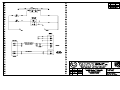
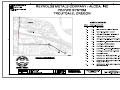
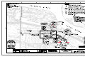
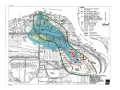
FE/PWO System Layout ....................................................................................................2-3
Generalized FE/PWO System Configuration and Operation Diagram ......................5-1
PDX/062970001.DOC
III
SECTION 1
Introduction
This final report documents the installation of the focused extraction/production well
optimization (FE/PWO) system at the Reynolds Metals Company Superfund site in
Troutdale, Oregon, as designed. This final report also provides documentation
demonstrating that the FE/PWO system is functioning as designed and is capable of
meeting required performance criteria as specified in the Unilateral Administrative Order for
Remedial Design and Remedial Action (Groundwater UAO) (EPA Docket No. CERCLA 102005-0217) (U.S. Environmental Protection Agency [EPA], August 2005). This
documentation is provided consistent with the requirements identified in the following
documents:
•
Memorandum WP No. 65: Work Plan for Focused Extraction System Design and Installation
(CH2M HILL, December 2004)
•
Groundwater UAO
•
Memorandum WP No. 69: Focused Extraction and Production Well Optimization System
Startup Performance Monitoring Plan (CH2M HILL, November 2005)
Work was conducted in accordance with the Record of Decision for Interim Remedial Action
(Interim ROD) (EPA, September 30, 2002). The Interim ROD identified the FE/PWO system
as the “Selected Interim Action Remedy” for removing and containing high fluoride levels
in groundwater in the east potliner and scrap yard areas and for minimizing the migration
of contaminant groundwater in the south plant area. The FE/PWO system involves
hydraulic containment through optimization of production well operation in the
intermediate- and deep-zone groundwater and enhanced focused extraction of groundwater
in the Upper Gray Sand (UGS) zone below the east potliner and scrap yard areas.
Remedial action objectives (RAOs) for site groundwater outlined in the Interim ROD
included the following:
•
Restore and maintain use of the intermediate and deep groundwater as a drinking water
source. The goal of restoration is to meet the federal and state safe drinking water
standards.
•
Minimize the migration of contaminants from waste and soil to groundwater, reduce
fluoride in shallow and intermediate groundwater, and control migration of
contaminant plumes in groundwater.
•
Control migration of fluoride to the Sandy River.
Site-specific remedial action goals identified for groundwater included the following:
•
Onsite containment of south plant fluoride plumes with concentrations exceeding the
maximum contaminant level (MCL), except for the area north of the U.S. Army Corps of
Engineers dike.
PDX/062970001.DOC
1-1
FE/PWO SYSTEM INSTALLATION
•
Statistically significant downward trend in fluoride concentrations in the UGS,
intermediate, and deep zones over time.
•
Reduction of total fluoride mass in shallow and intermediate zone groundwater.
•
Achievement of National Pollutant Discharge Elimination System (NPDES)
requirements for fluoride and other constituents of concern prior to discharge to the
Columbia River.
The elements required under Section V, Task 3 in Attachment 2 (Scope of Work for RMC
Superfund Site August 2005) of the Groundwater UAO are summarized in this final report.
The Administrative Order on Consent (AOC) requires that the final report present a goodfaith estimate of total costs; a description of the remedial action system and modifications; a
description of remedial action performance and monitoring; and appendixes containing all
relevant information.
This final report is organized into the following sections:
•
•
•
•
•
•
•
•
1-2
Section 1: Introduction
Section 2: FE/PWO System Installation
Section 3: FE/PWO System Modifications
Section 4: Performance Monitoring
Section 5: Operations and Maintenance
Section 6: Costs
Section 7: Certification
Appendixes
PDX/062970001.DOC
SECTION 2
FE/PWO System Installation
The remedial action for restoration of groundwater at the Reynolds Metals Company (RMC)
Superfund site relies on a combination of source control removal actions, institutional
controls, and hydraulic capture and containment of fluoride in groundwater. This report
documents the installation of the FE/PWO system, which provides hydraulic capture and
containment of fluoride in groundwater. The FE/PWO system is described more fully in
Specifications for Focused Extraction / Production Well Optimization for the RMC-Troutdale
Facility (CH2M HILL, April 2005). Source control removal actions are summarized in PostDemolition Remedial Investigation Report (CH2M HILL, June 2006). Institutional controls
restricting the use of shallow groundwater are a requirement of the Interim ROD and will be
addressed in future documents.
Construction of the FE/PWO system began in July 2005 and was completed in October 2005.
CH2M HILL was responsible for project design, bid document preparation, and submittal
review. Tetra Tech ECI was the general contractor onsite, responsible for site safety; civil,
mechanical, and electrical installation; system testing; and site cleanup. Construction
activities were accomplished in accordance with Specifications for Focused Extraction /
Production Well Optimization for the RMC-Troutdale Facility (CH2M HILL, April 2005).
System startup performance monitoring of the FE/PWO system began on November 4,
2005, and was completed in mid-November 2005. Monthly operational monitoring of the
FE/PWO system was initiated on November 21, 2005, and was completed in May 2006 in
accordance with the following plans:
•
Memorandum WP No. 68: Sitewide Groundwater Monitoring Plan (2006 Through 2010) at
RMC-Troutdale (CH2M HILL, October 2005)
•
Memorandum WP No. 69: Focused Extraction and Production Well Optimization System
Startup Performance Monitoring Plan (CH2M HILL, November 2005)
Monitoring of system performance is currently being performed quarterly according to the
requirements in Memorandum WP No. 68: Sitewide Groundwater Monitoring Plan (2006 Through
2010) at RMC-Troutdale (CH2M HILL, October 2005). This sitewide groundwater monitoring
plan provides the procedures and requirements necessary to monitor groundwater for the
next 5 years.
2.1 Focused Extraction/Production Well Optimization System
The FE/PWO system provides for the interception of high-fluoride-containing groundwater
migrating from the silt unit to the UGS zone (scrap yard and east potliner areas). It also
provides for the capture and removal of fluoride-containing groundwater that exceeds
drinking water MCLs in the Intermediate Sand and Deep Sand/Gravel zones (south plant
area). On the basis of numerical groundwater flow modeling, two focused extraction wells
PDX/062970001.DOC
2-1
FE/PWO SYSTEM INSTALLATION
pumping at a total rate of approximately 40 gallons per minute (gpm) and two production
wells pumping at a total flow rate of approximately 1,200 gpm are required to achieve final
selected remedy objectives. On the basis of initial modeling results, two focused extraction
wells (FE-02 and FE-03) were installed in the south plant in 2004 using cable tool drilling
techniques (Memorandum WP No. 65: Work Plan for Focused Extraction System Design and
Installation [CH2M HILL, December 2004]). The focused extraction wells are located along
the north side of the scrap yard and west of the east potliner area. Production well water
from production wells PW07 and PW08 (with backup capacity from PW03 and PW05) is
blended with the focused extraction well water prior to discharge to the Columbia River in
compliance with the plant’s existing NPDES permit (Oregon Permit No. 100757).
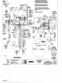
Major construction elements for the FE/PWO system included the following:
•
Modification of aboveground wellheads at production wells PW03, 05, 07, and 08 to
include new ductile iron pipe, check and gate valves, pressure indicators, and heat
tracing
•
Installation of pumps and controls at focused extraction wells FE02 and FE03, including
isolation and check valves, flow meters, pressure indicators, and heat tracing
•
Removal of the pump and motor from PW18 and reinstallation at PW05
•
Installation of conveyance piping from the focused extraction and production wells to
Building 70 for blending and discharge into the existing NPDES discharge line.
•
Upgrades to Building 70 to support installation of the motor control center, electrical
panels, NPDES sampling point/sink, focused extraction and production well line
plumbing, and a programmable logic computer for system operation.
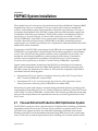
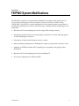
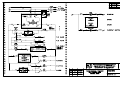
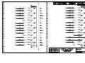
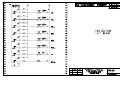
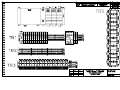
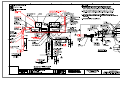
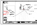
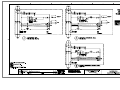
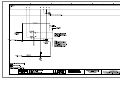
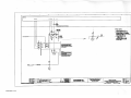
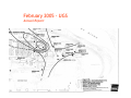
A general layout of the FE/PWO system is shown on Figure 2-1. Detailed system as-built
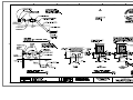
drawings of the FE/PWO system are included as Appendix A.
2.2 Performance Monitoring
Long-term groundwater monitoring will be conducted to evaluate the effectiveness of the
completed and ongoing cleanup actions. Monitoring and reporting for the first 5 years will
be accomplished in accordance with Memorandum WP No. 68: Sitewide Groundwater
Monitoring Plan (2006 Through 2010) at RMC-Troutdale (CH2M HILL, October 2005).
2-2
PDX/062970001.DOC
PDX/062970003.PDF
SECTION 3
FE/PWO System Modifications
The FE/PWO system was constructed and installed in accordance with Specifications for
Focused Extraction/Production Well Optimization System for the RMC-Troutdale Facility
(CH2M HILL, April 2005). No major modifications to the original design concept/basis or
specifications package were allowed. The following is a listing of minor changes approved
in the field:
•
Relocation of 12-inch discharge line north to align with existing roadway
•
Substitution of thrust block for restrained pipe connections at 12-inch discharge pipe to
16-inch NPDES pipe connection
•
Substitution of direct burial electrical wire for conduit
•
Minor plumbing realignments in Building 70 to improve trip hazards and access issues
•
Addition of NPDES automatic ISCO sampling port, equipment, and piping within
Building 70
•
Relocation of 12-inch discharge line exit from Building 70
•
Flow meter substitution for FE02 and FE03
PDX/062970001.DOC
3-1
SECTION 4
Performance Monitoring
Startup performance monitoring of the system began on November 4, 2005, and was
completed in mid-November 2005, as detailed in Focused Extraction and Production Well
Optimization System Startup Performance Monitoring Plan (CH2M HILL, November 2005).
Startup monitoring included implementation of the following:
•
Step tests at FE02 and FE03
•
One week of baseline monitoring
•
Constant-rate pump tests at FE02 and FE03
Continuous operation and performance monitoring of the FE/PWO system began on
November 21, 2005, and was completed in May 2006 in accordance with the following work
plans:
•
Memorandum WP No. 68: Sitewide Groundwater Monitoring Plan (2006 Through 2010) at
RMC-Troutdale (CH2M HILL, October 2005)
•
Memorandum WP No. 69: Focused Extraction and Production Well Optimization System
Startup Performance Monitoring Plan (CH2M HILL, November 2005)
Monitoring of system performance is currently being performed quarterly according to the
requirements in Memorandum WP No. 68: Sitewide Groundwater Monitoring Plan (2006 Through
2010) at RMC-Troutdale (CH2M HILL, October 2005). This sitewide groundwater monitoring plan
provides the procedures and requirements necessary to monitor groundwater for the next 5 years.
Detailed results from the system startup and 5-month performance monitoring of the
FE/PWO system are presented in Appendix B. This presentation was provided to
representatives of EPA and the Oregon Department of Environmental Quality (DEQ) on
May 25, 2006, and finalized and documented in Technical Memorandum GW No. 35, Focused
Extraction/Production Well Optimization System Startup Performance Monitoring Results and
Conclusions (CH2M HILL, June 27, 2006). Data collected during system startup and
performance monitoring activities and performance implications are summarized below:
•
Pumping rates for FE02 and FE03 achieved 27 and 25 gpm, respectively. These pumping
rates exceed the Interim ROD requirement.
•
Contour maps and drawdown plots demonstrate that the FE wells’ pumping influence
extends to the edge of existing fluoride plumes. Observed performance validates
previous model results. System performance is consistent with the model and the
Interim ROD.
•
Fluoride and cyanide concentrations initially decreased in FE02 after startup. By the end
of the performance monitoring period, fluoride and cyanide concentrations equilibrated
at 40 milligrams per liter (mg/L) and 4 mg/L, respectively.
PDX/062970001.DOC
4-1
FE/PWO SYSTEM INSTALLATION
•
Fluoride and cyanide concentrations initially increased in FE03 after startup. By the end
of the performance monitoring period, fluoride and cyanide concentrations equilibrated
at 20 mg/L and 0.1 mg/L, respectively.
•
Drawdown and data evaluation validate conclusions that no additional focused
extraction wells are required to establish hydraulic control in areas where fluoride
concentrations exceed the limits established in the Interim ROD.
•
One additional monitoring well in the east potliner area was recommended to improve
system performance assessment. This well, MW58, was installed in September 2006.
•
The FE/PWO system is meeting Interim ROD remedial action objectives.
On the basis of FE/PWO system startup and performance monitoring data collected in 2005
and 2006, the startup and operation requirements identified in the Groundwater UAO (EPA,
August 5, 2005) have been satisfied and the FE/PWO system is capable of meeting
established performance criteria.
4-2
PDX/062970001.DOC
SECTION 5
Operations and Maintenance
The FE/PWO system is designed to provide hydraulic containment of fluoride plumes in
the south plant area and to capture and remove high-fluoride-concentration groundwater in
the vicinity of the scrap yard and east potliner areas. During system operation, groundwater
is removed through a combination of shallow focused extraction wells (FE02 and FE03) and
a minimum of two of four deep production wells (PW3, PW5, PW7, and PW8).
Groundwater from the focused extraction wells flows through a 4-inch-diameter
underground pipe to Building 70, where it is mixed with water from PW07 and PW08 (or
PW03 and PW05 during backup conditions). Groundwater from the production wells is
transported to Building 70 via 8- and 10-inch-diameter underground pipe. After mixing, the
combined flow from the FE/PWO system is discharged to a 12-inch-diameter underground
pipe that connects to an existing 16-inch-diameter underground pipe located adjacent to
Sundial Road. The 16-inch-diameter pipe discharges to the Columbia River under an
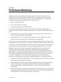
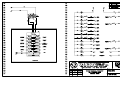
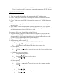
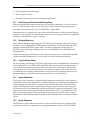
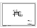
existing NPDES permit (Oregon Permit No. 100757). Figure 5-1 schematically illustrates the
general flow, mixing, and discharge of the extracted groundwater by the FE/PWO system.
Figure 5-1
Generalized FE/PWO System Configuration and Operation Diagram
Operations and maintenance (O&M) of the FE/PWO system are expected to continue for a
minimum of 5 years. Regular inspection, maintenance, and troubleshooting of the FE/PWO
system are required throughout this period. Required O&M activities are attached as
Appendix C (Operation, Inspection, and Maintenance Manual—Focused Extraction/Production
Well Optimization System, RMC-Troutdale Facility [CH2M HILL, October 2006]).
PDX/062970001.DOC
5-1
SECTION 6
Costs
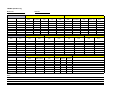
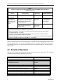
Costs for the FE/PWO system installation are summarized in Table 6-1. Included in the
table are costs for CH2M HILL, Tetratech ECI, and other subcontractors. Costs incurred by
EPA and RMC/Alcoa are not included.
TABLE 6-1
Summary of Costs for Focused Extraction/Production Well Optimization System Installation
Contractor
Description of Work
Cost*
CH2M HILL
Preliminary FE Well Design
•
Work planning
•
Design basis development
•
Reporting
CH2M HILL,
Geotech Exploration/
Boart Longyear
FE Well Design and Installation
•
Detailed design
•
Well Drilling and Installation Services
•
Reporting
$70,683
CH2M HILL
FE/PWO System Design
•
Engineering Support
•
Work planning
•
Design and specification preparation
•
Owner construction oversight
•
Agency submittals
•
Reporting
$ 206,085
Tetratech ECI,
Turnkey Construction Services,
Tice Electric
System Installation
•
Mechanical /Electrical Services
•
Pumps, Motor Control Center, Piping
•
As-built drawings
$671,082
$109,132
Total
$1,056,982
*EPA oversight and RMC/Alcoa costs not included.
PDX/062970001.DOC
6-1
PDX/062970012.PDF
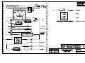
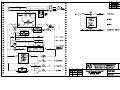
7-1
APPENDIX A
FE/PWO System As-Built Drawings
PDX/062970001.DOC
PDX/062960011.PDF
PDX/062960011.PDF
PDX/062960011.PDF
PDX/062960011.PDF
PDX/062960011.PDF
PDX/062960011.PDF
PDX/062960011.PDF
PDX/062960011.PDF
PDX/062960011.PDF
PDX/062960011.PDF
PDX/062960011.PDF
PDX/062960011.PDF
PDX/062960011.PDF
PDX/062960011.PDF
PDX/062960011.PDF
PDX/062960011.PDF
PDX/062960011.PDF
PDX/062960011.PDF
PDX/062960011.PDF
PDX/062960011.PDF
PDX/062960011.PDF
PDX/062960011.PDF
PDX/062960011.PDF
PDX/062960011.PDF
PDX/062960011.PDF
PDX/062960011.PDF
PDX/062960011.PDF
PDX/062960011.PDF
PDX/062960011.PDF
PDX/062960011.PDF
PDX/062960011.PDF
PDX/062960011.PDF
PDX/062960011.PDF
PDX/062960011.PDF
PDX/062960011.PDF
PDX/062960011.PDF
PDX/062960011.PDF
APPENDIX B
FE/PWO Performance Monitoring
PDX/062970001.DOC
TECHNICAL MEMORANDUM GW No. 35
Focused Extraction/Production Well Optimization
System Startup Performance Monitoring Results and
Conclusions
PREPARED FOR:
Chip Humphrey/EPA
Curt Black/EPA
PREPARED BY:
Scott Dethloff/CH2M HILL
Ken Trotman/CH2M HILL
Kira Sykes/CH2M HILL
COPIES:
Mavis Kent/DEQ
Steve Shaw/Reynolds Metals Company
Mark Stiffler/Alcoa
DATE:
June 27, 2006
PROJECT NUMBER:
166034.07.09.10
This memorandum provides documentation that the Focused Extraction/Production Well
Optimization (FE/PWO) system installed at the Reynolds Metals Company Troutdale
Superfund site is complete and operational. This memorandum further provides
documentation that demonstrates that the FE/PWO system is functioning as designed and
is capable of meeting the established performance criteria. This documentation is provided
consistent with the requirements identified in the following:
•
Unilateral Administrative Order (UAO) for Remedial Design and Remedial Action, Docket No.
CERCLA 10-2005-0217 (U.S. Environmental Protection Agency [EPA], August 5, 2005)
•
Memorandum WP No. 65: Work Plan for Focused Extraction System Design and Installation
(CH2M HILL, December 2004)
•
Memorandum WP No. 69: Focused Extraction and Production Well Optimization System
Startup Performance Monitoring Plan (CH2M HILL, November 2005)
Technical information is provided in this memorandum as a PowerPoint presentation
(Attachment). This presentation was provided to representatives of EPA and the Oregon
Department of Environmental Quality (DEQ) on May 25, 2006.
Background Information
Construction of the FE/PWO system began in July and was completed in October 2005.
Installation of this groundwater remediation system was completed as required in
accordance with the UAO.
TECH MEMO STARTUP PERF MONITORING RESULTS VER3.DOC
COPYRIGHT 2006 BY CH2M HILL, INC. • COMPANY CONFIDENTIAL
1
FOCUSED EXTRACTION/PRODUCTION WELL OPTIMIZATION SYSTEM STARTUP PERFORMANCE MONITORING RESULTS AND CONCLUSIONS
Major construction elements for the FE/PWO system included the following:
•
Modification of the aboveground wellheads at production wells PW03, 05, 07, and 08 to
include new ductile iron pipe, check and gate valves, pressure indicators, and heat
tracing
•
Installation of pumps and controls at focused extraction wells FE02 and FE03, including
isolation and check valves, flowmeters, pressure indicators, and heat tracing
•
Removal of the pump and motor from PW18 and reinstallation of this equipment at
PW05
•
Upgrades to Building 70 and installation of the motor control center, electrical panels,
and a programmable logic computer for system operation
•
Installation of conveyance piping from the FE and production wells to the existing
National Pollutant Discharge Elimination System (NPDES) discharge line
Startup performance monitoring of the system began on November 4, 2005. Startup
monitoring included implementation of step tests at FE02 and 03, one week of baseline
monitoring, and then constant-rate tests at FE02 and FE03. Startup monitoring was
completed in mid-November and continuous operation of the FE/PWO system began on
November 21, 2005. Performance monitoring of the system was completed in May 2006 in
accordance with the following work plans:
•
Memorandum WP No. 68: Sitewide Groundwater Monitoring Plan (2006 Through 2010) at
RMC-Troutdale (CH2M HILL, October 2005)
•
Memorandum WP No. 69: Focused Extraction and Production Well Optimization System
Startup Performance Monitoring Plan (CH2M HILL, November 2005)
Report Organization
The attached PowerPoint presentation has been modified slightly from the original
presented on May 25, 2006. Because the meeting included discussion of topics other than
groundwater, slides not related to the FE/PWO system have been deleted. In addition, three
slides (numbers 13, 15, and 32) addressing agency comments provided after the meeting
have been included. Slide 41 (previously slide 43) was revised to match the system start time
as used in the other slides.
Information included in the attached PowerPoint presentation is organized as follows:
•
Slides 1 to 5: Introductions, performance monitoring objectives, schedule, and testing
summary
•
Slides 6 to 12: System flow rates and baseline (2005) groundwater contour maps
•
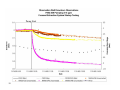
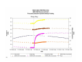
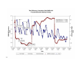
Slides 13 to 19: Precipitation and Columbia River stage data, startup hydrographs,
drawdown observations, and FE well recovery data
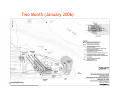
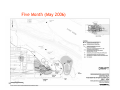
•
Slides 20 to 26: Groundwater elevation contour maps in South Plant area, pre-pumping
through conclusion of the startup period (November 2005 to May 2006)
TECH MEMO STARTUP PERF MONITORING RESULTS VER3.DOC
COPYRIGHT 2006 BY CH2M HILL, INC. • COMPANY CONFIDENTIAL
2
FOCUSED EXTRACTION/PRODUCTION WELL OPTIMIZATION SYSTEM STARTUP PERFORMANCE MONITORING RESULTS AND CONCLUSIONS
•
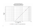
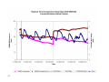
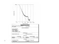
Slides 27 to 30: Drawdown and recovery observations and straight line distance
drawdown plots for FE02 and FE03
•
Slides 31 to 32: Fluoride concentration reduction predictions in upper gray sand (UGS)
and intermediate groundwater zones, from Focused Feasibility Study (CH2M HILL, June
2000), Figures A-34 and A-33
•
Slides 33 to 36: Data analysis information
•
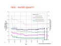
Slides 37 to 47: Water quality and mass removed data summaries
•
Slides 48 to 50: Summary information
Conclusions
Data collected over the November 2005 to May 2006 startup period, and summarized in the
attached PowerPoint presentation, demonstrate that the system performance is consistent
with expectations as defined in the Focused Feasibility Study:
•
Groundwater contour maps demonstrate good capture of the fluoride plume.
•
Distance drawdown plots show that pumping influences extend to the edges of the
known fluoride plume.
•
The observed system performance matches microfem modeling results prepared for the
Focused Feasibility Study.
•
Fluoride concentration trends indicate capture and that mass is being removed by the
system.
On the basis of the above information, it is the conclusion of RMC and CH2M HILL that the
startup and operation requirements identified in the Unilateral Administrative Order for
Remedial Design and Remedial Action (EPA, August 5, 2005) have been satisfied and the
system is capable of meeting the established performance criteria.
TECH MEMO STARTUP PERF MONITORING RESULTS VER3.DOC
COPYRIGHT 2006 BY CH2M HILL, INC. • COMPANY CONFIDENTIAL
3
ATTACHMENT
PowerPoint Presentation
May Monthly Agency Meeting
Risk and Groundwater Focus
Reynolds Metals Company/Alcoa Troutdale Facility
May 25, 2006
FE/PWO PERFORMANCE
MONITORING
• Review of Objectives and Reporting
• Performance Evaluation Results
• Conclusions
FE/PWO PMP Objectives
3
•
Establish operation pumping rates at FE02-046 and FE03-045
•
Determine the area of influence of the focused extraction system
•
Determine fluoride and cyanide concentration trends during the
focused extraction system startup
•
Determine whether additional focused extraction wells are required
to establish hydraulic control over the area where fluoride
concentrations exceed the limits established in the Record of
Decision (ROD)
•
Determine whether additional piezometers are required to assess
system performance
FE/PWO PERFORMANCE MONITORING
4
AQUIFER TEST
• Step Test
• Baseline Water Level Monitoring
• FE02 Constant-Rate Pumping Test
• FE02 Recovery Phase
• FE02/FE03 Constant-Rate Pumping Test
5
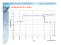
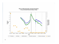
FE02 and FE03 Flow Rates
Establish operation pumping rates at FE02-046 and FE03-045
6
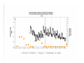
Combined Flow Rate
Flow Rate (mgd)
FE02, FE03, PW3, PW7, PW8
7
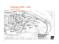
February 2003 - UGS
Annual Report
8
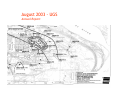
August 2003 - UGS
Annual Report
9
August 2004 - UGS
Annual Report
10
February 2005 - UGS
Annual Report
11
August 2005 - UGS
Annual Report
12
13
Baseline
14
FE02
Recovery
FE02/FE03
15
15
Baseline
16
FE02
Recovery
FE02/FE03
Pump Start
17
Pump Stop
Pump Start
18
Pump Stop
19
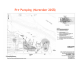
Pre-Pumping (November 2005)
20
53 hr (November 2005)
21
One Month (December 2005)
22
Two Month (January 2006)
23
Three Month (February 2006)
24
Four Month (April 2006)
25
Five Month (May 2006)
26
27
2 Hours FE02 Drawdown
Straight Line Distance Drawdown Plot
Focused Extraction Startup Testing
28
2 Hours FE02 Recovery
Straight Line Distance Drawdown Plot
Focused Extraction Startup Testing
29
4 Hours FE02 / FE03 Drawdown
Straight Line Distance Drawdown Plot
Focused Extraction Startup Testing
30
MICROFEM OUTPUT – FFS
31
32
33
34
Focused Extraction Start Up
35
Focused Extraction Start Up
36
37
Total Cyanide Concentration (mg/L)
Total Cyanide Mass (lb/day)
Flow Rate (gpm)
Fluoride Concentration (mg/L)
Fluoride Mass (lb/day)
FE02 – WATER QUALITY
38
Total Cyanide Concentration (mg/L)
Total Cyanide Mass (lb/day)
Flow Rate (gpm)
Fluoride Concentration (mg/L)
Fluoride Mass (lb/day)
FE03 – WATER QUALITY
39
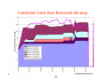
Mass Removal Rate (lb/day)
Flow Rate (mgd)
Fluoride Concentration (mg/L)
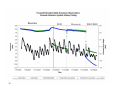
COMBINED WATER QUALITY
Fluoride Mass Removed (lb/day)
Combined Total Mass Removed (lb/day)
40
41
5/17/2006
5/10/2006
5/3/2006
4/26/2006
4/19/2006
4/12/2006
4/5/2006
3/29/2006
3/22/2006
3/15/2006
3/8/2006
3/1/2006
2/22/2006
2/15/2006
2/8/2006
2/1/2006
1/25/2006
1/18/2006
1/11/2006
1/4/2006
12/28/2005
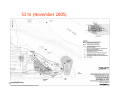
12/21/2005
12/14/2005
12/7/2005
11/30/2005
11/23/2005
11/16/2005
11/9/2005
11/2/2005
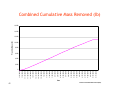
Mass
FFluoride
lo u rid e M
ass (lb)
(lb s)
Combined Cumulative Mass Removed (lb)
16,000
14,000
12,000
10,000
8,000
6,000
4,000
2,000
0
Date
Fluoride Cumulative Mass Removed (lbs)
Cross Section - South Plant
42
Cross Section 6-6’ - Scrap Yard
43
Cross Section 5-5’ - East Potliner Area
44
Fluoride Trends in UGS – Scrap Yard
45
Fluoride Trends in UGS – East Potliner
46
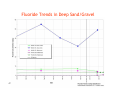
Fluoride Trends in Deep Sand/Gravel
47
Summary
• Establish operation pumping rates at FE02-046 and FE03-045
– FE-02 at approximately 27 gpm.
– FE-03 at approximately 25 gpm.
– Current rates meet or exceed Interim ROD requirement.
– Continue to monitor.
• Determine the area of influence of the focused extraction
system
Use multiple lines of evidence for capture:
• Contour maps demonstrate good capture.
• Distance Drawdown plots show that pumping influences extend to edge of
plumes.
• Observed performance matches model results (results validate a model
that shows capture).
• Concentration trends indicate capture (mass is being removed!).
These lines of evidence demonstrate system performance
consistent with model results and Interim ROD
48
Summary (Continued)
• Determine fluoride and cyanide concentration trends
during the focused extraction system startup
– FE-02: fluoride initially decreased, now constant at 40 mg/L.
Cyanide (same trend), now constant at 4 mg/L.
– FE-03: fluoride slightly increasing, now at approx. 20 mg/L.
Cyanide constant at 0.10 mg/L.
• Determine whether additional focused extraction wells
are required to establish hydraulic control over the area
where fluoride concentrations exceed the limits
established in the Record of Decision (ROD)
– No additional extraction wells needed to meet RAOs.
49
Summary (Continued)
• Determine whether additional piezometers are
required to assess system performance
– One additional monitoring well in the East Potliner
area.
• The FE system performance is meeting the
Interim ROD RAOs
• FE system meeting intent to remove mass
50
APPENDIX C
Operation, Inspection, and Maintenance
Manual—Focused Extraction/Production
Well Optimization System,
RMC-Troutdale Facility
(CH2M HILL, October 2006)
PDX/062970001.DOC
Operation, Inspection, and
Maintenance Manual - Focused
Extraction/Production Well
Optimization System, RMCTroutdale Facility
Reynolds Metals Company
TR OUTDAL E FAC IL IT Y
October 2006
\\ROSA\PROJ\ALCOA\166034\MAINTENANCE MANUAL\FINAL\TO SHAW 101706\FE-PWO SYSTEM FINAL_101706.DOC
\\ROSA\PROJ\ALCOA\166034\MAINTENANCE MANUAL\FINAL\TO SHAW 101706\FE-PWO SYSTEM FINAL_101706.DOC
1.0 Introduction
The Reynolds Metals Company (RMC) Troutdale facility is the site of a former aluminum
reduction plant that ceased operations in the fall of 2000 and was subsequently demolished
from 2003 through January 2006. Based on soil and groundwater contamination from past
plant operations in the east potliner and scrap yard area a Focused Extraction and
Production Well Optimization (FE/PWO) system was installed to provide hydraulic
containment and removal of groundwater containing high levels of fluoride. Final
construction of the FE/PWO system was completed in October 2005 and continuous
operation of the FE/PWO system began on November 21, 2005. This manual describes the
system configuration and outlines procedures to operate, inspect, and maintain the
FE/PWO system. Individual system component operation, inspection and maintenance
procedures can be found in the manufacturer' literature. This manual includes a schedule
for the inspection and maintenance of the FE/PWO system and individual system
components.
3
OPERATION, INSPECTION, AND MAINTENANCE MANUAL - FOCUSED EXTRACTION/PRODUCTION WELL OPTIMIZATION SYSTEM, RMC-TROUTDALE FACILITY
\\ROSA\PROJ\ALCOA\166034\MAINTENANCE MANUAL\FINAL\TO SHAW 101706\FE-PWO SYSTEM FINAL_101706.DOC
4
OPERATION, INSPECTION, AND MAINTENANCE MANUAL - FOCUSED EXTRACTION/PRODUCTION WELL OPTIMIZATION SYSTEM, RMC-TROUTDALE FACILITY
2.0 Objectives
Project specific objectives for the FE/PWO system include:
•
•
•
•
•
Flow and drawdown from the focused extraction (FE) wells sufficient to capture and
remove groundwater with high levels of fluoride in the Upper Gray Sand (UGS) zone in
the vicinity of the scrap yard and east potliner sites.
Flow and drawdown from the production (PW) wells sufficient to provide hydraulic
containment of fluoride plumes in the south plant area.
Combined FE/PWO discharge to the Columbia River that meet existing plant National
Pollutant Discharge Elimination System (NPDES) permit levels.
Combined FE/PWO discharge to the Columbia River that does not exceed 5 mg/l for
fluoride.
Operation and maintenance of the system for a minimum of 5 years.
This plan is organized into the following sections:
1.0
2.0
3.0
4.0
5.0
6.0
7.0
Introduction
Objectives
System Overview and Operation
Operation Procedures
Inspection Procedures
Maintenance Procedures
Recordkeeping
Appendix A – As-built Drawings and Diagrams
Appendix B – Operation Procedures
Appendix C – Inspection Procedures
Appendix D – Maintenance Procedures
Appendix E – Operation, Inspection, and Maintenance Logs and Schedules - Forms
Appendix F – Operation Log - Data
Appendix G – Maintenance Log – Data
\\ROSA\PROJ\ALCOA\166034\MAINTENANCE MANUAL\FINAL\TO SHAW 101706\FE-PWO SYSTEM FINAL_101706.DOC
5
OPERATION, INSPECTION, AND MAINTENANCE MANUAL - FOCUSED EXTRACTION/PRODUCTION WELL OPTIMIZATION SYSTEM, RMC-TROUTDALE FACILITY
\\ROSA\PROJ\ALCOA\166034\MAINTENANCE MANUAL\FINAL\TO SHAW 101706\FE-PWO SYSTEM FINAL_101706.DOC
6
OPERATION, INSPECTION, AND MAINTENANCE MANUAL - FOCUSED EXTRACTION/PRODUCTION WELL OPTIMIZATION SYSTEM, RMC-TROUTDALE FACILITY
3.0 System Overview and Operation
The FE/PWO system is designed to provide hydraulic containment of fluoride plumes in
the south plant area and to capture and remove high fluoride concentration groundwater in
the vicinity of the scrap yard and east potliner areas. During system operation, groundwater
is removed through a combination of shallow focused extraction wells (FE02 and FE03) and
a minimum of two of four deep production wells (PW03, PW05, PW07, and PW08).
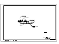
Groundwater removed by the operating focused extraction and production well is blended
and discharged to the Columbia River. Figure 1 illustrates the locations of the focused
extraction, production, and monitoring wells; piping sizes; and general system layout.
Detailed system design information including pipe size, and valve, meter, and gauge
locations are illustrated in the as-built drawings included in Appendix A.
System Flow Layout
In general, groundwater from the focused extraction wells flows through a 4-inch diameter
underground pipe to Building 70 and blends with groundwater from the production wells.
Groundwater from the production wells is transported to Building 70 via 8-inch and 10-inch
diameter underground pipes. After blending, the combined flow from the FE/PWO system
is discharged to a 12-inch diameter underground pipe that connects to an existing 16-inch
diameter pipe located adjacent to Sundial Road. The 16-inch diameter pipe discharges to the
Columbia River under an existing NPDES Permit (Oregon Permit # 100757, EPA Permit #
OR-0000060). Figure 2 illustrates the general flow, mixing, and discharge of the extracted
groundwater by the FE/PWO system.
Major Components
The FE/PWO system is comprised of a few major component groups. These major
component groups include:
•
•
•
•
•
•
Focused extraction wells and assemblies
Production wells and assemblies
System controls and Motor control center (MCC)
Discharge line and assemblies
Sample Basin and Automatic Samplers
Building 70 and system areas
\\ROSA\PROJ\ALCOA\166034\MAINTENANCE MANUAL\FINAL\TO SHAW 101706\FE-PWO SYSTEM FINAL_101706.DOC
7
Mixing
Point
Well
PW 05
Well
PW 03
Well
FE 03
Well
PW 08
Well
FE 02
Well
PW 07
OPERATION, INSPECTION, AND MAINTENANCE MANUAL - FOCUSED EXTRACTION/PRODUCTION WELL OPTIMIZATION SYSTEM, RMC-TROUTDALE FACILITY
Building 70
NPDES Discharge to the Columbia River
Figure 2 – Generalized FE/PWO System Configuration and Operation Diagram
\\ROSA\PROJ\ALCOA\166034\MAINTENANCE MANUAL\FINAL\TO SHAW 101706\FE-PWO SYSTEM FINAL_101706.DOC
9
OPERATION, INSPECTION, AND MAINTENANCE MANUAL - FOCUSED EXTRACTION/PRODUCTION WELL OPTIMIZATION SYSTEM, RMC-TROUTDALE FACILITY
\\ROSA\PROJ\ALCOA\166034\MAINTENANCE MANUAL\FINAL\TO SHAW 101706\FE-PWO SYSTEM FINAL_101706.DOC
10
OPERATION, INSPECTION, AND MAINTENANCE MANUAL - FOCUSED EXTRACTION/PRODUCTION WELL OPTIMIZATION SYSTEM, RMC-TROUTDALE FACILITY
4.0 Operation Procedures
The FE/PWO system should be operated such that the capture and containment of the
fluoride plume beneath the site is optimized as outlined in the Reynolds Metals Company
Superfund Site, Troutdale, Oregon, Record of Decision for Final Remedial Action (USEPA,
September 29, 2006). To achieve this performance requirement, the system was designed to
operate with two PW wells running at approximately 600 gallons per minute (gpm) each in
conjunction with two FE wells running at approximately 20 gpm each. The system was
planned with PW-07 and PW-08 as the primary production wells and PW-03 and PW-05
available as backup production wells as needed. This arrangement allows continued
operation in the event of primary production well shutdown and maintenance or the need
for additional pumping capacity to sustain satisfactory performance and discharge
requirements. The FE/PWO system includes an interlock safeguard to prevent the FE wells
from running if the PW wells are not operational. Operation of the system is expected to
continue for a minimum of 5 years. FE/PWO system operation procedures include:
OP-01 – System Startup/Shutdown Procedures
OP-02 – Sample Sink/Sample Discharge Return Pump Procedures
OP-03 – NPDES Sample Collection Procedures
OP-04 – Routine Operating Tasks
OP-05 – Flow Adjustment of FE Wells and Pumps
A detailed description for each operational procedure is included in Appendix B.
Procedures for operation of individual system components can be found in the
manufacturer' literature.
\\ROSA\PROJ\ALCOA\166034\MAINTENANCE MANUAL\FINAL\TO SHAW 101706\FE-PWO SYSTEM FINAL_101706.DOC
11
OPERATION, INSPECTION, AND MAINTENANCE MANUAL - FOCUSED EXTRACTION/PRODUCTION WELL OPTIMIZATION SYSTEM, RMC-TROUTDALE FACILITY
\\ROSA\PROJ\ALCOA\166034\MAINTENANCE MANUAL\FINAL\TO SHAW 101706\FE-PWO SYSTEM FINAL_101706.DOC
12
OPERATION, INSPECTION, AND MAINTENANCE MANUAL - FOCUSED EXTRACTION/PRODUCTION WELL OPTIMIZATION SYSTEM, RMC-TROUTDALE FACILITY
5.0 Inspection Procedures
Regular inspection and monitoring of the FE/PWO system is essential in identifying
necessary maintenance and continued system operation throughout 5 year minimum
operational; period. FE/PWO system inspection procedures include:
IP-01 – Focused Extraction Wells
A detailed description for the focused extraction wells inspection procedure is included in
Appendix C. Procedures for the inspection of individual system components can be found
in the manufacturer’s literature. A schedule of recommended routine inspections and
preventative maintenance required for the FE/PWO system including the individual system
components is provided in Appendix E, FE/PWO Routine Inspection and Preventive
Maintenance Schedule/Log.
\\ROSA\PROJ\ALCOA\166034\MAINTENANCE MANUAL\FINAL\TO SHAW 101706\FE-PWO SYSTEM FINAL_101706.DOC
13
OPERATION, INSPECTION, AND MAINTENANCE MANUAL - FOCUSED EXTRACTION/PRODUCTION WELL OPTIMIZATION SYSTEM, RMC-TROUTDALE FACILITY
\\ROSA\PROJ\ALCOA\166034\MAINTENANCE MANUAL\FINAL\TO SHAW 101706\FE-PWO SYSTEM FINAL_101706.DOC
14
OPERATION, INSPECTION, AND MAINTENANCE MANUAL - FOCUSED EXTRACTION/PRODUCTION WELL OPTIMIZATION SYSTEM, RMC-TROUTDALE FACILITY
6.0 Maintenance Procedures
Regular routine maintenance and troubleshooting of the FE/PWO system is essential to
ensure system functioning throughout the minimum 5 year operational period. FE/PWO
system maintenance procedures include:
MP-01 – System Piping in Building 70, Evacuation/Line Breaking
MP-02 – Focused Extraction Well Pump System, Isolation/Line Breaking
MP-03 – Cleaning Focused Extraction Well Flow Totalizer
A detailed description for each maintenance procedure is included in Appendix D.
Procedures for maintenance of the individual system components can be found in the
manufacturer' literature. A schedule of recommended routine inspections and preventative
maintenance required for the FE/PWO system including the individual system components
is provided in Appendix E, FE/PWO Routine Inspection and Preventive Maintenance
Schedule/Log
\\ROSA\PROJ\ALCOA\166034\MAINTENANCE MANUAL\FINAL\TO SHAW 101706\FE-PWO SYSTEM FINAL_101706.DOC
15
OPERATION, INSPECTION, AND MAINTENANCE MANUAL - FOCUSED EXTRACTION/PRODUCTION WELL OPTIMIZATION SYSTEM, RMC-TROUTDALE FACILITY
\\ROSA\PROJ\ALCOA\166034\MAINTENANCE MANUAL\FINAL\TO SHAW 101706\FE-PWO SYSTEM FINAL_101706.DOC
16
OPERATION, INSPECTION, AND MAINTENANCE MANUAL - FOCUSED EXTRACTION/PRODUCTION WELL OPTIMIZATION SYSTEM, RMC-TROUTDALE FACILITY
7.0 Recordkeeping
Recordkeeping is an integral part of operating the FE/PWO system. Good recordkeeping
will help identify potential maintenance and repair/replacement needs early and is
necessary to problem-solve potential malfunctions or operational problems. Detailed and
complete notes must be documented in the operation, inspection and maintenance logs on a
regular basis. Recordkeeping of the FE/PWO system involves the following major steps:
1. Record general operating, inspection, and maintenance details including observation
date, time, observer, observer affiliation, and other notes on the general condition of the
system.
2. Record the detailed operating data required on the FE/PWO Operation Log (Appendix F).
Also record and report any alarms, observed cleaning needs, housekeeping needs,
malfunctions, damaged equipment, non-operational equipment, etc.
3. Record completed routine inspections and preventive maintenance routines on the
FE/PWO Routine Inspection and Preventive Maintenance Schedule/Log (Appendix E).
4. Record both preventive and breakdown maintenance data including maintenance date,
time, actions, methods, parts replaced outcomes, etc. on FE/PWO System Maintenance Log
(Appendix G), with details in supplemental notes. Retain any manufacturer or
contractor correspondence regarding these actions.
\\ROSA\PROJ\ALCOA\166034\MAINTENANCE MANUAL\FINAL\TO SHAW 101706\FE-PWO SYSTEM FINAL_101706.DOC
17
Appendix A – As-built Drawings and Diagrams
Appendix A, As-Built Drawings and Diagrams, is included as Appendix A in the main body
of the report (Focused Extraction/Production Well Optimization System Installation) and is not
repeated again in this appendix due to the large file size.
Appendix B – Operation Procedures
FE/PWO System Operation Procedure OP-01
Procedure No.
Procedure:
Min. Frequency
Original Date:
Revision Date:
Updates:
OP-01
System Startup/Shutdown Procedures
Upon Occurrence
June 26, 2006
None
None
OPERATING PARAMETERS:
• The system should be operated such that the capture and containment of the
contaminated groundwater plume is maximized.
• The system should be operated such that the discharge limits established for the
NPDES permit and the final Record of Decision (ROD) are not exceeded.
• To achieve these performance requirements, the FE/PWO system was designed to
operate with two Production Wells (PW) {operating at 600 gpm each} and two
Focused Extraction (FE) wells {operating at 20 gpm each} running in conjunction.
• The construction of the production wells in the water-bearing zone consists of
perforated pipe without a filter pack in a sandy formation. As such it is
recommended that the production wells not be operated at a flow rate higher than
their historic operating flow rate so as not to over-stress the formation. The historic
high flow rates were limited by system pressures of approximately 45 psi. Therefore
do not operate the production wells with less than 45-psi backpressure. (If wear has
reduced the capacity of the pump the backpressure may be reduced further in order to
keep capacity at a minimum of 600 gpm).
• Currently the production wells are operating with 55-psi backpressure at
approximately 800 gpm.
• Production well backpressure can be adjusted by opening or closing the gate valve
adjacent to the production well and observing the upstream pressure gauge.
• The FE well construction consists of a filter packed well screen in the targeted waterbearing zone. Aquifer tests indicate the pumps can be run full open.
• The focused extraction wells are capable of operated full open at approximately 27
gpm.
• Operating experience has shown that build up of scale and slime can result in
plugged well screens, pumps, and piping resulting in reduced yield/flow.
• The flow from the FE well pumps should be controlled to prevent exposing the top
of the well screen.
• Inspection of the water level in the well is covered under Inspection Procedure IP-01:
• Focused extraction well motors are interlocked to the production well motors, such
that at least one of the production well motors must be running in order for either of
the focused extraction wells to run.
• The system is plumbed to allow use of up to four production wells (PW 3, 5, 7 or 8).
The primary production wells are PW 7 and PW 8, with PW 3 and PW 5 available as
backup in case maintenance of a primary well is required or additional capacity is
needed to satisfy performance requirements.
MOTOR STARTER CONTROL:
•
•
•
Each well motor start switch is a three position toggle switch; HAND, OFF, and
AUTO and is located on the respective starter compartment on the Motor
Control Center (MCC).
o Select HAND – to energize motor
o Select OFF – to stop motor
o Select AUTO – for potential future automation
Each motor starter control contains a green, red and amber light with a PUSH
TO TEST LAMP feature.
o Red indicates motor is RUNNING
o Green indicates motor is STOPPED
o Amber indicates ALARM condition
If motor has shut down because of an alarm condition, press ALARM RESET
before restarting the motor.
SEQUENCE OF OPERATION:
Startup Procedure
1. Inspect electrical equipment, plumbing, and controls for signs of hazards or damage.
2. Start primary production wells PW 7 and PW 8, or backup wells as appropriate.
3. Start focused extraction wells FE-02 and FE-03.
4. Adjust the flow rate from the FE well pumps as described in Operation Procedure
OP-05.
5. Adjust production well back-pressure to 55 pounds per square inch (psi) at each
operating PW well. (Backpressure may be reduced in order to keep capacity at a
minimum of 600 gpm per well)
6. Record start-up date and time in the operation log, in the adjustments sections.
7. Weekly, record flow rates, total flows, pressures, hour meter readings and depth to
water in the FE wells on the FE/PWO Operation Log.
8. If an FE flow meter is reading “0”, record the flow and the number of hours it was
reading zero (flow meter screen will alternate between “0” flow and the number of
hours since zero flow began) on the FE/PWO Operation Log and follow Maintenance
Procedure MP-03.
Shutdown Procedure
1. Record current operating data in the operating log prior to shutdown.
2. Inspect energized equipment, plumbing, and controls for signs of hazards or
damage.
3. Shut off focused extraction wells (FE-02 and FE-03).
4. Shut off primary production wells PW 7 and PW 8, or backup wells as appropriate.
5. Verify that all PW and FE well motors are de-energized.
6. Lockout, tag and try activation of all PW and FE well motors before conducting
maintenance activities.
7. Record shutdown date, time, and purpose, in the operating log, in the adjustment
section.
FE/PWO System Operation Procedure OP-02
Procedure No.
Procedure:
Min. Frequency
Original Date:
Revision Date:
Updates:
OP-02
Sample Sink/Sample Discharge Return Pump Procedures
Upon Occurrence
June 26, 2006
None
None
OPERATING PARAMETERS:
• The Sample Discharge Return Pump (SDRP-1) returns water from the sink to the
system discharge piping.
• SDRP-1 is an Osmonics Tonkaflo SS Series Pump.
• SDRP-1 can be operated in the manual or automatic mode using the three position
selector switch located adjacent to the sink in Bldg 70.
• In the automatic mode the sink level is controlled by two liquid level switches.
o The high level switch opens solenoid valve SV-1 in the pump discharge
line and energizes SDRP-1 when wet.
o The low level switch closes solenoid valve SV-1 and deenergizes SDRP-1
when dry.
o A third level switch in the sink (high high level) controls solenoid valve
SV-2 and is discussed further in Operation Procedure OP-03.
• The sink is used for the collection and discharge of sample water from the system and
purge water from the monitoring wells, as allowed under the facilities NPDES permit.
• Water discharged from the sink is normally returned to the system discharge piping
ahead of the NPDES sampling port. However, to facilitate draining the system piping
in Bldg 70, the discharge from SDRP-1 may be routed to the downstream side of the
12” gate valve (See: Maintenance Procedure MP-01).
• A 3-way ball valve is provided on the inlet of SDRP-1 to allow an alternate inlet source
to SDRP-1 (See: Maintenance Procedure MP-01- System Piping in Building 70,
Evacuation/Line Breaking).
MOTOR STARTER CONTROL:
•
SDPR-1 motor start switch is a three position toggle switch; HAND, OFF, and
AUTO and is located adjacent to the sink in Bldg 70.
o Select HAND – to energize motor (Handle is spring loaded to return to
OFF
o Select OFF – to stop motor
o Select AUTO – for automatic operation, allowing the sink level switches
to control the pump motor
•
•
The motor starter control contains a green, red and amber light with a PUSH TO
TEST LAMP feature.
o Red indicates motor is RUNNING
o Green indicates motor is STOPPED
o Amber indicates ALARM condition
If motor has shut down because of an alarm condition, press ALARM RESET
before restarting the motor
SEQUENCE OF OPERATION:
1. Turn 3-way ball valve handle to the point toward the 2” sink drain pipe.
2. Open 1” ball valve discharging into 2” discharge line from the focused extraction
wells.
3. Close 1” ball valve discharging into 12” discharge line downstream of 12” gate
valve.
4. For manual operation: Turn selector switch to HAND. Spring return will return
selector to OFF when handle is released.
5. For normal operation: Set selector switch to AUTO. The switch should be left in
the auto position.
6. With a soft brush, gently clean the three sink basin level switches including the
moving joints.
FE/PWO System Operation Procedure OP-03
Procedure No.
Procedure:
Min. Frequency
Original Date:
Revision Date:
Updates:
OP-03
NPDES Sampling Procedures
Upon Occurrence
June 28, 2006
None
None
OPERATING PARAMETERS:
•
•
•
•
•
•
•
•
•
•
•
Samples are to be collected for chemical analysis as required by the facility’s
National Pollutant Discharge Elimination System (NPDES) permit and the Final
Record of Decision (ROD).
Samples are collected from the sample line which runs from the discharge pipe
of the combined FE/PWO streams (NPDES discharge) to a sink in Building 70.
Grab samples can be collected at that sink using the manual gate valve.
Flow proportional composite samples are collected using an ISCO 3700
Refrigerated Automatic Samplers, which draws a sample from a sample vessel
that is fed by the sample line.
The sample line feeds the sample vessel continuously when solenoid valve, SV-2
is programmed to be open. The sample vessel overflows into the sink were the
sample discharge return pump (SDRP-1) pumps the water back into the NPDES
discharge line. (See: Operation Procedure OP-02)
SV-2 must be programmed to be open to coincide with the sampling event
programmed for the ISCO composite sampler.
See the Wastewater Quality Assurance Manual and ISCO 3700 Portable Sampler
Instruction Manual for instructions on the operation, maintenance and
programming of the composite sampler.
Programming SV-2 to open is accomplished via the programmable logic
controller panel view interface (Allen-Bradley PanelView 300 Micro) as described
below.
The panel view interface on the MCC has three main timer screens; two screens
for setting values and a third screen for monitoring both timers.
1. SET SAMPLE TIME TO START
2. SET SAMPLE FLOW DURATION
3. TIME UNTIL START
4. TIME LEFT ON SAMPLE
SV-2 is also controlled by the high-high level switch in the sink. SV-2 will close if
the high-high level switch is wet, but will reopen if programmed to be open and
the high level switch is dry. If the high-high level switch in the sink is wet, a
message SINK HIGH HIGH LIMIT – LEFT ARROW will show on all timer screens
until manually reset.
SV-2 should be programmed to open in advance of the ISCO sampler starting
time, to purge water from the line and should continue to be open for a sufficient
period of time to insure collection of the 24-hour composite sample. (i.e., SV-2
Open ½ hour before ISCO compositor starts and continue open for 25 ½ hours)
SEQUENCE OF OPERATION:
Startup Procedure
1. Turn 3-way ball valve handle to the point toward the 2” sink drain pipe.
2. Open 1” ball valve where SDRP-1 discharge line enters the 2” line from focused
extraction wells.
3. Close 1” ball valve where SDRP-1 discharge line enters the 12” NPDES discharge
line.
4. With a soft brush, gently clean the three sink basin level switches including the
moving joints.
5. Place SDRP-1 control switch (located adjacent to the sink) in the AUTO position.
6. Flush the Y-strainer immediately upstream of SV-2 by opening the blow down valve
and discharging any collected solids into the sink.
Programming SV-2 to open (Sample Water to Start Flowing)
1. Program the ISCO sampler to collect a composite sample on a convenient date
consistent with NPDES permit requirements. (See Wastewater Quality Assurance
Manual and ISCO 3700 Portable Sampler Instruction Manual for instructions on the
operation and programming of the composite sampler)
2. Program SV-2 using the panel view.
3. Set the starting time to open SV-2.
a. Toggle to the screen titled, SET SAMPLE TIME TO START
i.
Press or to toggles through all screens
ii.
Or Press to toggles through the three timer screens only
b. Select hours
i.
Press F2 and then Press
ii.
Or Press or until the cursor is just to the left of hours and then Press
c. Set hours value on sub screen
i.
Select numerical position
1.
Press or
ii.
Select numerical value for each position
1.
Press or
iii.
Press after all values are entered
d. Select minutes
i.
Press F3 and then Press
ii.
Or Press or until the cursor is just to the left of minutes and then
Press
e. Set minutes value on sub screen
i.
Select numerical position
1.
Press or
ii.
Select numerical value for each position
1.
Press or
Press after all values are entered. (Note: You cannot set minutes to 0. If
you attempt to set minutes at 0, the program will use the previous minutes
setting)
4. Set the duration time for SV-2 to be open.
iii.
a. Once an acceptable duration time as been established, the duration timer should
not have to be reset
b. Toggle to the screen titled, SET SAMPLE FLOW DURATION
i.
Press or to toggles through all screens
ii.
Or Press to toggles through the three timer screens only
c. Select hours
i.
Press F2 and then Press
ii.
Or Press or until the cursor is just to the left of hours and then Press
d. Set hours value on sub screen
i.
Select numerical position
1.
Press or
ii.
Select numerical value for each position
1.
Press or
iii.
Press after all values are entered
e. Select minutes
i.
Press F3 and then Press
ii.
Or Press or until the cursor is just to the left of minutes and then
Press
f. Set minutes value on sub screen
i.
Select numerical position
1.
Press or
ii.
Select numerical value for each position
1.
Press or
2.
Press after all values are entered
5. Toggle to the screen titled, SAMPLE TIME UNTIL START - TIME LEFT ON
SAMPLE
a. Press or to toggles through all screens
b. Or Press to toggles through the three timer screens only
6. Start sample cycle
a. Press F1,
i.
A seconds timer will show on the screen and SAMPLE TIME UNTIL
START and TIME LEFT ON SAMPLE will show time remaining on their
respective timers as time elapses
ii.
All timer screens will show the message COUNTING DOWN TO SAMPLE
TIME until SV-2 open, then the message will change to SAMPLE FLOW ON
iii.
When the cycle is complete, SAMPLE TIME UNTIL START and TIME
LEFT ON SAMPLE will reset to their previous value and all timer screens
will show the message SAMPLE CYCLE OFF.
Other Related Panel View Procedures
1. To stop sample cycle before it is complete
a. Press F4
b. All timer screens will show the message SAMPLE CYCLE OFF
2. If the high-high level switch in the sink is wetted, a message SINK HIGH HIGH LIMIT
– LEFT ARROW will show on all timer screens until manually reset
a. To manually reset, Press
FE/PWO System Operation Procedure OP-04
Procedure No.
Procedure:
Min. Frequency
Original Date:
Revision Date:
Updates:
OP-04
Routine Operating Tasks
Weekly
September 22, 2006
None
None
OPERATING ROUTINES:
1. Check for alarms and general equipment conditions for indications of maintenance
needs.
2. Rotate standby pumps by briefly starting and stopping the motor.
3. During cold weather, check for tripped GFCI breakers (5) on the heat trace system
and correct as necessary.
4. During cold weather, check for proper operation of the heat trace system by
inspecting indicator lights (8 locations). Indicator light and heart trace should be on
at approximately 40 degrees.
5. Measure the depth to water in the focused extraction wells. See Inspection Procedure
IP-01.
6. Inspect the production wells for excessive packing leakage.
7. Record required data and completion of the above routine operating procedures on the
FE/PWO Operation Log and report any maintenance requirement.
FE/PWO System Operation Procedure OP-05
Procedure No.
Procedure:
Min. Frequency
Original Date:
Revision Date:
Updates:
OP-05
Flow Adjustment of Focused Extraction Wells and Pumps
Upon Occurrence
June 27, 2006
None
None
OPERATING PARAMETERS:
• The Focused Extraction Well Pumps should be operated such that the capture and
containment of the contaminated groundwater plume is maximized.
• The system should also be operated such that the discharge limits established for the
NPDES permit and the final Record of Decision (ROD) are not exceeded.
• To achieve these performance requirements, the system was designed for two
Focused Extraction (FE) wells to pump at 20 gpm each.
• The FE well construction consists of a filter packed well screen in the targeted waterbearing zone. Aquifer tests indicate the pumps can be run full open.
• Operating experience has shown that build up of scale and slime can result in
plugged well screens, pumps and piping resulting in reduced yields/flows.
• The flow from the FE well pumps should be controlled to prevent exposing the top
of the well screen.
• Inspection of the water level in the well is covered by Inspection Procedure IP-01
• This operation procedure is intended to be used if the results of inspection procedure
IP-01 indicate the water level is below the well screen or the FE well is pumping
below the design flow of 20 gpm.
• Additional troubleshooting procedures for the FE pumps are available in the Goulds
Pumps 4” Submersible Pumps Installation and Maintenance Manual on page 20.
MOTOR STARTER CONTROL:
• Each well motor start switch is a three position toggle switch; HAND, OFF, and
AUTO and is located on the respective starter compartment on the Motor Control
Center (MCC).
o Select HAND – to energize motor
o Select OFF – to stop motor
o Select AUTO – for potential future automation
• The motor starter control contains a green, red and amber light with a PUSH TO
TEST LAMP feature.
o Red indicates motor is RUNNING
o Green indicates motor is STOPPED
o Amber indicates ALARM condition
• If motor has shut down because of an alarm condition, press ALARM RESET before
restarting the motor.
ADJUSTMENT PROCEDURE:
Groundwater Level Elevation is Below the Top Elevation of the Well Screen
If the groundwater level elevation is below the top elevation of the well screen the flow
rate from the extraction well must be reduced. This is best done by throttling back the FE
flow rate. Step-by-step procedures include:
1. During pump operation, slowly close the discharge valve(s) until the flow from the
FE well measures 20 gpm. Do not exceed 150 psi pressure at the pump discharge or
the pressure relief valve will open and discharge water back into the well.
2. Measure the groundwater elevation and determine if the water level is a minimum
of 1 foot above the top of the screen (See Inspection Procedure IP-01 for details). If
the groundwater elevation does not meet exceed the minimum 1 foot above screen
criteria, the well may require rehabilitation. Reduce pump flow as much as possible
without causing the pressure relief valve to open and schedule maintenance as soon
as possible. Continuing to operate the pump with the water level below the screen
can exacerbate plugging or damage to the screen. Continuing to operate at less than
20 gpm may not provide sufficient groundwater capture.
3. If, after reducing the flow to 20 gpm, the groundwater elevation is significantly
above the top to the well screen, the flow rate may be increased to optimize
groundwater capture.
4. Slowly open the discharge valve(s) until the steady-state elevation is a minimum of 1
foot above the top of the well screen.
5. Record the final steady-state depth to groundwater, well flow rate, and pressure.
The FE pump is operating below the minimum flow rate (20 gpm)
1. Verify that the pump is on at the MCC and that all discharge line valves in Bldg 70
are fully opened.
2. Pump operation should also be confirmed by observing the pressure and flow at the
pump.
3. If the pump is not pumping, the pressure gauge may still show system pressure but
no flow will be observed. Negative flow may be observed if the line check valve (if
so equipped) and the pump’s internal check valve fail. Negative flow may also be
observed if the sample line is opened and the line check valve only (if so equipped)
fails.
4. If the pump is operational, measure the depth to water in the well. (See Inspection
Procedure IP-01 for details)
5. Operating experience has shown that build up of scale and slime can result in
plugging the pump discharge valve if the valve has been throttled back to reduce
flow as described in the first procedure above. Attempt to open the pump discharge
valves. If this successfully increases the flow rate, thoroughly exercise the valve to
break up and clear the scale.
6. If the water level is significantly above the top of the well screen, slowly open the
discharge valves and continue to measure the water level in the well. Maintain the
steady-state water level a minimum of 1 foot above the top of the well screen.
7. If pump discharge is already fully opened or further opening is unsuccessful at
increasing flow, measure the depth to water in the well, record the information. If
the depth to water in the well is above the top of the pump, then at a minimum,
pump repair is indicated. If the depth to water is below the top of the screen then
well rehabilitation may also be required.
8. Measure the depth to water in a nearby monitoring well and compare it to the water
level in the FE well to further ascertain the condition of the FE well. A high
differential compared to the start up condition is an indication the FE well requires
rehabilitation.
9. After repair/replacement of the pump only, without rehabilitation of the well,
exercise caution when restarting the pump. Be aware that the well may also need
maintenance. If the well screen is plugged the pump may be quickly starved for
water. Throttle back the pump and measure the depth to water and follow the steps
2 thru 5 under the section, Groundwater Level Elevation is Below the Top Elevation of the
Well Screen, and determine if additional well maintenance is required.
Appendix C – Inspection Procedures
FE/PWO System Inspection Procedure IP-01
Procedure No.
Procedure:
Min. Frequency
Original Date:
Revision Date:
Updates:
IP-01
Focused Extraction Well Inspection
Weekly
June 27, 2006
None
None
INSPECTION PARAMETERS:
•
•
•
•
•
The focused extraction (FE) wells require routine inspection approximately every
week.
Water levels within the FE wells must remain above the top elevation of the well
screen.
The FE well pumps must be positioned within the well sump below the well
screen, and a minimum pump flow rate of 20 gpm must be maintained for
optimal FE well operation.
Detailed pump operating and maintenance procedures are available in the
Goulds Pumps 4” Submersible Pumps Installation and Operation Instructions.
Detailed start up procedures for the FE pumps are found in Operation Procedure
OP-01
INSPECTION POINTS:
1. Identify if the area around the wellhead is clear of debris and heavy over-growth.
2. Visually inspect the FE wellhead and associated piping and wiring for obvious
damage or maintenance needs (i.e. corrosion, breakage, etc).
3. Inspect the heat trace system and the pressure relief valve according to the
FE/PWO Routine Inspection and Maintenance Schedule/Log
4. Measure the depth to water within each FE well during pump operation via the
drop tube access on top of the well seal. Record the depth to water on FE/PWO
Operation Log and compare the measured value to the depth to the top of the
well screen in the table below and determine if the groundwater level is a
minimum of 1 foot above the top of the well screen.
Critical Pump/Well Measurements (Feet)
FE 02
FE 03
Depth to Top of Well Screen*
38.18
37.22
Max Desired Depth to Water*
37.18
36.22
Elevation to Top of Well Screen**
-5.90
-6.90
Min Desired Elevation to Water**
-4.90
-5.90
Depth to Top of Pump*
50.01
Depth to Bottom of Pump*
53.47
Depth to Bottom of Well*
58.18
57.22
*Depth to top of well screen, water and top and bottom of pump are
measured from the top of the well casing
**Elevation datum is NGVD
5. Record the flow rate and pressure at which the pump is currently operating.
6. If FE well and assembly is not operating correctly as described, refer to
Operation Procedure OP-05.
7. Record and report all inspection observations and any maintenance needs on the
FE/PWO Operation Log.
Appendix D – Maintenance Procedures
FE/PWO System Maintenance Procedure MP-01
Procedure No.
Procedure:
Min. Frequency
Original Date:
Revision Date:
Updates:
MP-01
System Piping in Building 70, Evacuation/Line Breaking
Upon Occurrence
June 27, 2006
None
None
PURPOSE:
In the event that system piping in Building 70 must be drained for maintenance
purposes such as maintenance of the MAGFLO flow meter, or the double check valves,
the following procedure should be used to drain the piping using the Sample Discharge
Return Pump (SDRP-1) and minimize spills.
MOTOR STARTER CONTROL:
•
Each well motor start switch is a three position toggle switch; HAND, OFF, and
AUTO and is located on the respective starter compartment on the Motor
Control Center (MCC).
o Select HAND – to energize motor
o Select OFF – to stop motor
o Select AUTO – for potential future automation
•
The SDPR-1 motor start switch is a three position toggle switch; HAND, OFF,
and AUTO and is located adjacent to the sink in Building 70.
o Select HAND – to energize motor (Handle is spring loaded to return to
OFF)
o Select OFF – to stop motor
o Select AUTO – for automatic operation, allowing the sink level switches
to control the pump motor
•
The motor starter control contains a green, red and amber light with a PUSH TO
TEST LAMP feature.
o Red indicates motor is RUNNING
o Green indicates motor is STOPPED
o Amber indicates ALARM condition
If motor has shut down because of an alarm condition, press ALARM RESET
before restarting the motor.
•
SEQUENCE OF OPERATION:
1. De-energize all production wells and focused extraction well motors.
2. Lockout; tag and try activation of all production wells and focused extraction
well motors.
3. Close the 12” gate valve on the 12” system discharge piping.
4. Open the 1” ball valve in the SDRP-1 discharge line where it discharges into the
12” system discharge piping, immediately downstream of the 12” gate valve.
5. Close the 1” ball valve discharging into the 2” discharge line from the focused
extraction wells.
6. Connect a 1” hose from the drain line under the 12” discharge pipe, to the 3-way
ball valve on the inlet of SDRP-1.
7. Turn the 3-way ball valve handle to point toward the hose connection.
8. Open the 1” drain valve under the 12” discharge pipe near doorway.
9. Energize SDRP-1 using selector switch adjacent to the sink – Turn the handle to
HAND position and hold.
10. Run SDRP-1 until the piping is drained. DO NOT run the SDRP-1 without
water.
FE/PWO System Maintenance Procedure MP-02
Procedure No.
Procedure:
Min. Frequency
Original Date:
Revision Date:
Updates:
MP-02
Focused Extraction Well Pump System, Isolation/Line Breaking
As Required
September 28, 2006
None
None
PURPOSE:
• Operating experience has shown that scale periodically builds up in the focused
extraction wells screen, well pumps, and discharge piping and component parts.
• Scale also builds up on the throttle/isolation valves, which require maintenance in
order to gain complete shut off of the valve to isolate the affected piping system.
• Following are the recommended procedures to isolate the focused extraction (FE)
well pump FE 03 to facilitate pump removal, or to clean the flow totalizer or other
component parts.
• Note: The FE 02 discharge piping contains a second in line check valve between the
flow totalizer and the pump. If this check valve is functioning, line pressure will still
be trapped between the throttle/shut off valve and the check valve if using the
procedure for FE 03.
• Use the Alternate Procedure to isolate FE 02 or to isolate the entire FE discharge
system from both pumps up to the 2” double check valve in Bldg 70.
MOTOR STARTER CONTROL:
•
Each well motor start switch is a three position toggle switch; HAND, OFF, and
AUTO and is located on the respective starter compartment on the Motor
Control Center (MCC).
o Select HAND – to energize motor
o Select OFF – to stop motor
o Select AUTO – for potential future automation
•
The motor starter control contains a green, red and amber light with a PUSH TO
TEST LAMP feature.
o Red indicates motor is RUNNING
o Green indicates motor is STOPPED
o Amber indicates ALARM condition
If motor has shut down because of an alarm condition, press ALARM RESET
before restarting the motor.
•
SEQUENCE OF OPERATION:
Isolate Flow Totalizer and/or Focused Extraction Well Pump FE 03
1. Before de-energizing the focused extraction (FE) well pump, open and close the
throttle/shut off valve down stream of the flow totalizer several times to break
up and loosen any scale that may have built up on the seats of the valve. As the
valve is closed, backpressure will increase and flow will be reduced but the flow
velocity across the seating surfaces of the valve will increase and help to flush the
scale from the valve seats. When the pressure increases to 150 psi, the pressure
relief valve will open and water will be discharge back into the well. The relief
valve is capable of handling the full flow from the pump. However, it is not
recommended that this condition be allowed to continue for an extended period
of time since the back pressure will immediately drop and cause the pressure
relief valve to close, allowing the back pressure to build and the pressure relief
valve to reopen again, rapidly cycling and causing undue wear and tear on the
pressure relief valve and the pump.
2. Open the throttle/shut off valve until the pump is de-energized.
3. Stop and de-energize well pump FE 03, lockout, tag and try.
4. Close the throttle/shut off valve down stream of the FE 03 well pump and flow
totalizer.
5. Open the sample line valve to relieve the pressure between the pump and the
throttle/shut off valve. [Note: The pump is equipped with an internal check
valve, which will otherwise result in trapping pressure between the pump and
the throttle/shut off valve.]
6. Observe the pump side pressure gauge to confirm that pressure has been
relieved from the piping between the pump and the throttle shut off valve. If not
repeat step 1 and 5 without re-energizing the pump, until the discharge pressure
and flow from sample line are zero. If pressure and flow from the sample line
are still not at zero follow the alternate procedure below. [Note: FE 02 discharge
piping contains a second in line check valve between the flow totalizer and the
pump. If this check valve is functioning, line pressure will be trapped between
the throttle/shut off valve and the check valve. This will require the alternate
procedures to safely isolate FE 02 well pump or remove the flow totalizer from
the FE 02 piping system.]
Alternate Procedure: Isolate Flow Totalizer and/or Focused Extraction Well Pump FE 02
and/or FE 03
1. Stop and de-energize FE 02 and FE 03. Lockout, tag, and try.
2. Close the downstream ball valve on the 2”double check valves in Bldg 70.
3. Open the 1” ball valve in the SDRP-1 discharge line where it discharges into the
12” system discharge piping, immediately downstream of the 12” gate valve.
4. Close the 1” ball valve discharging into the 2” discharge line from the focused
extraction wells.
5. Connect tubing to test port 1 (upstream end) on the 2” double check valve and
run the tubing to the sample sink.
6. Place the SDRP-1 control in the AUTO position. See Operation Procedure OP 2.
7. Open test port 1 on the 2” double check valve and discharge the water into the
sink. SDRP-1 will be controlled by the level switches in the sink and will
discharge the water downstream of the 2” double check valve.
8. Open the sample line on the FE 02 and FE 03 system piping.
9. These procedures should result in relieving the pressure from all FE discharge
piping. Open the sample line at FE 02 to relief the pressure between the FE 02
well pump and the second in line check valve.
10. Observe the FE system discharge piping and confirm that the pressure in the
section of line to be opened is in fact reduced to zero.
11. It is now safe to break the line to the pump or to remove the flow totalizer for
cleaning.
12. If one of the two FE well pumps is expected to be out of service for an extended
period of time and the throttle/shut off valve will not fully close the line should
be capped to allow start-up of the other FE well pump.
FE/PWO System Maintenance Procedure MP-03
Procedure No.
Procedure:
Min. Frequency
Original Date:
Revision Date:
Updates:
MP-03
Cleaning Focused Extraction Well Flow Totalizer
As Required
September 28, 2006
None
None
PURPOSE:
• A Signet 8150 battery powered flow totalizer provides the measure of flow rate and
total flow from each of the focus extraction well pumps.
• This flow totalizer is a paddle wheel type recorder.
• Operating experience has shown that scale periodically builds up on the paddle
wheel and piping enough to stop operation of the flow totalizer and indicate zero
flow.
• Scale also builds up on the throttle/isolation valves, which require maintenance in
order to gain complete shut off of the valve and isolate the affected piping system.
• Following is a procedure for determining if the flow meter is plugged and the steps
necessary to clean the flow meter.
SEQUENCE OF OPERATION:
Determine If Flow Meter Is Plugged
1. If the FE flow meter is indicating zero flow, slowly close the throttle valve
downstream of the flow meter.
2. Observe for increased pressure at the pump discharge pressure gauge and listen
for increased noise coming from the throttle valve.
3. If pressure and noise increase and the flow meter remains at zero the meter is
likely plugged. Follow the steps below to clean the meter.
4. If the pressure does not increase above line pressure, verify that the pump is on.
5. If the pump is on but not able to exceed line pressure then repair/replacement of
the pump is indicated.
Clean FE Flow Meter
1. Complete the Focused Extraction Well Pump System Line Breaking Procedure
MP-02.
2. Carefully unscrew the sensor cap, mounting the flow totalizer to the system
piping. Caution: If pressure still exists in the pipeline, the flow totalizer may
rapidly jump out of the pipe when the connection is fully broken. Stand to the
side.
3. Remove the totalizer with a firm but gentle lifting and rotating motion.
4. Remove the paddle wheel and pin from the sensor tube by gently prying with a
screwdriver between the sensor tube tab and the paddle wheel until the pin is free.
(See manufacturer’s instructions)
5. Clean all scale buildup from the paddle wheel, pin and sensor tube.
6. Clean all scale buildup inside the pipe adapter fitting.
7. Lubricate the paddle wheel, pin, sensor tube and adapter fitting with a light film
of silicon lubricant.
8. Reassemble flow totalizer and install in the pipe adapter using a firm but gentle
rotating motion in the same orientation as when removed, with the paddle wheel
perpendicular to the flow. (See manufacturer’s instruction for further details)
9. Close sample line valves.
10. Open throttle/shut off valves.
11. Re-energize FE well pumps.
12. Record this activity on the FE/PWO System Maintenance Log.
13. Record the activity and the flow rate, pressure and depth to water on the FE/PWO
Operations Log in the adjustment section.
Appendix E – Operation/Inspection/Maintenance Logs
and Schedules - Forms
Routine Inspection and Maintenance Schedule/Log
Month _______________ Year _______________
Date and inititial in the space provided when inspection or maintenance task is complete
Unit
Item
Allen-Bradley PanelView 300 Micro Interface / MicroLogix
1500 Programmable Controller
System Operation
Allen-Bradley MicroLogix 1500 Programmable Controller
Building 70
Errors/Faults
First Aid Kit
Routine
Inspection
Frequency
Suggested Routine Inspection Points
Routine
Inspection
Date Completed
Routine
Maintenance
Frequency
Suggested Routine Maintenance
Monthly
Check that system operation is normal by toggling
through display screens
As necessary
Troubleshoot system operation problems
Monthly
Inspect program controller for error/faults. An error exist
if all indicator LED’s are off, the POWER and FAULT
are solid, or the POWER LED is solid and FAULT LED
is flashing.
As necessary
Troubleshoot errors.
Monthly
First Aid Kit is located in designated area, is fully
stocked, and is in good condition.
As necessary
Restock first aid kit.
As necessary
Promptly troubleshoot and repair Building 70 problems
as encountered.
Building 70
General Building Condition
Monthly
Inspect for general building condition including: poor
exterior paint, roof leaks, unacceptable building
temperatures, structural integrity, cracks in walls or
foundation, foundation settling, insect/rodent problems,
etc.
Building 70
Vegetation/Weeds
Monthly
Keep the building vicinity clear of excessive
vegetation/weeds that may create hazards or problems.
Annually
Spraying herbacide on vegetation surrounding building.
Building 70
Forced Air Heater
Semiannual
Producing heat, turning on as designed, and is clean.
Annually
Clean heating element and heater cabinet.
Troubleshoot operation.
Building 70
Building Lighting
Monthly
Lamps functioning properly
As necessary
Replace lamp bulbs (48" Type 32W T8).
As necessary
Replace, refill, and/or re-certify.
Building 70
Fire Extinguisher
Monthly
Fire extinguisher is located in designated area, is full,
and certification is current. Also, date and initial the
inspection tag
Building 70
Eye Wash Station
Monthly
Inspect that eye wash station is clear of obstructions, is
clean, and operational. Check that wash fluid is current
Semi Annually
Clear obstructions, clean, test operation and drain old
fluid. Replace wash fluid and date the tag
Building 70
Building Door and Lock
Monthly
Building door is in good condition, paint is not
pealing/flaking, and opens easily. Lock is lubricated,
undamaged, free of corrosion, and operational.
As necessary
Repair door, hinges, and/or locking latches. Repaint
door as needed. Replace or lubricate lock as necessary.
System Piping
FE Pump Pressure Relief Valve
Annually
Test pressure relief valve to 150 psi tp confirm
operation.
As necessary
Repair/Replace as necessary
Monthly
Check for errors (indicated by blinking triangle on
transmitter display) Check error types (per section 8.7.2
in Sitrans F M Magflo Handbook)
As necessary
Address errors and/or clear log
Every 2-4 years
MAGFLO 5100W Flow Sensor/Transmitter
Error/Status Log
Motor Control Center
Motor Indicator Lights
Monthly
Indicator light function (Push To Test). Clean exterior of
MCC and Panel
Osmonic Tonkaflo SS Series Pumps (SDRP-1)
Motor
Monthly
Check that motor cooling air passages are not blocked
As necessary
Clear cooling air passages
Osmonic Tonkaflo SS Series Pumps (SDRP-1)
Mechanical Seals
Monthly
Check for excessive leakage
As necessary
Replace Mechanical Seal
Monthly
Inspect for oil leaks. Inspect containment for presence
of oil
As necessary
Repair leaks, remove excess oil from containment
Substation
500 KVA Transformer
Routine
Maintenance
Date Completed Notes:
Deleete
Replace indicator lights.
Added
Added
Substation
System Piping
System Piping
Yard
Ashcroft Pressure Gauges
Double Check Valves
Monthly
Inspect for presence of vegetation
Monthly
Inspect for: Erratic or random pointer motion. Readings
that are suspect (especially when the true pressure is 0
psig). Broken windows. Leakage of gauge fill. Any signs
of service media leakage through the gauge.
Discoloration of gauge fill that impedes readability.
As necessary
Annually
Test for proper operation in accordance with the
manufacturers written procedures
As necessary
Overall System
Access
System Piping
Discharge Pipe/Outfall
PW Wells Pumps/Motors
General Condition
Monthly
PW Wells Pumps/Motors
Pump Foundation
Semiannual
PW Wells Motors
Motor Insulation
Annually
Annually
Spraying herbacide on vegetation inside and
surrounding substation yard
Replace, repair, or calibrated pressure gauges.
Service/Repair as needed
Spray herbicide and clear/cut vegetation as necessary
to allow access to all well pumps and monitorings wells
Inspect above-ground discharge pipe and outfall for
damage, corrosion, or otherwise repair needs.
As necessary
Repair as necessary.
Check for excess vibration of the pump
As necessary
Troubleshoot and rebuild as necessary
Check pump foundation for settling.
As necessary
Troubleshoot any pump foundation settling.
Annually
Megger motor winding insulations
As necessary
Rewind/Rebuild motor
Monthly
Check lubrication level and add oil as necessary. Use
Mobile DTE 26 or equivalent
Semiannual
Annually
Change oil in motor bearing Use Mobile DTE 26 or
equivalent
Annually
Grease bearing annually for continuous service.
Grease bearing once per 3 years for reduced service.
Use, Chevron SR 2 or equivalent
PW Wells Motors
Motor Bearings
PW Wells 3 and 7, Motors
Upper Motor Bearings
PW Wells Pumps/Motors
Pump Packing
Monthly
Inspect pump packing for excessive leaking.
PW Wells Pumps/Motors
Pump and Motor Exterior
Cleaning
Monthly
Check for exterior cleanilness of pump and motor and
that motor cooling air passages are not blocked
PW Wells Pumps/Motors
Pump Performance
Annually
Measure total dynamic head and flow. Take power
readings.
As necessary
Repair/Replace if capacity drops below 600 gpm
Signet 8150 Flow Totalizers
Battery Replacement
Monthly
Low battery indicator is displayed.
Every 4 years
Replace Lithium batteries per section 5 of Signet 8150
Flow Totalizer User's Manual
Tyco Thermal Controls Heat Tracing System
General System
Yokagawa mR1000 Recorder
Monthly
Clean oil and dirt from the pump and motor exterior and
clear cooling air passages
Annually
Perform conmissioning test as detailed in Raychem
Industrial Heat-Tracing Installation and Maintenance
Manual sections 8 -10
Refill chart paper per 3.2 of Yokogawa mR10000
Recorder User's Manual
Monthly
Check if paper supply sufficient until next scheduled
change ( 744 cm required for 31 days at chart speed of
10mm/hr )
BiMonthly
Felt Pen or Plotter Pens
Monthly
Check if recorded lines and printed characters are clear
As necessary
Recorder Cleanliness
Monthly
Clean exterior of recorder
Internal Light LED
Monthly
Check that LED brightness still sufficient or LED has not
burned out.
Every 2 years
Replace LED light per 11.3 of Yokogawa mR10000
Recorder User's Manual (2 years = half life of
brightness at default setting)
Display
Monthly
Display is clean, bright, and operating correctly.
Every 5 years
Replace display (5 years = half life of brightness at
default setting)
Yokagawa mR1000 Recorder
Yokagawa mR1000 Recorder
Add grease, adjust packing gland or replace packing as
necessary
Chart Paper
Yokagawa mR1000 Recorder
Yokagawa mR1000 Recorder
As necessary
Annually
Replace felt pen or plotter pens per 3.3 of Yokogawa
mR10000 Recorder User's Manual
Clean Recorder per 11.2 of Yokogawa mR10000
Recorder User's Manual
Added
Yokagawa mR1000 Recorder
Yokagawa mR1000 Recorder
Yokagawa mR1000 Recorder
Yokagawa mR1000 Recorder
Yokagawa mR1000 Recorder
Yokagawa mR1000 Recorder
Yokagawa mR1000 Recorder
Notes:
Chart Paper Feed Motor
Monthly
Operating correctly.
Every 5 years
Replace chart paper feed motor
Plotter Carriage
Monthly
Operating correctly.
Every 5 years
Replace plotter carriage
Recorder Motor
Monthly
Operating correctly.
Every 5 years
Replace motor
Lever Bearing
Monthly
Operating correctly.
Every 5 years
Replace lever bearing
Pen Servo
Monthly
Operating correctly.
Every 5 years
Replace pen servo
Recorder Calibration
Monthly
Measurement accuracy has declined. Compare to
Siemens Mag 5000 Flow Transmitter
Annually
Recalibrate recorder per 11.4 of Yokogawa mR10000
Recorder User's Manual
Pen Position
Monthly
Recording is inaccurate.
Annually
Adjust pen position per 11.5 of Yokogawa mR10000
Recorder User's Manual
Appendix F – Operation Logs - Data
FE/PWO Operation Log
Month/Year:
Observer:
Focused Extraction Well 2
Date
Time
Flow Rate
(GPM)
Total Flow
(1000 Gallons)
Pressure
(PSI)
Production Well 3
Date
Time
Pressure
(PSI)
Time
Flow Rate
(GPM)
Hour
Meter
Depth to water*
(Ft)
Date
* Depth to Top of Screen FE 02 = 38.18 ft
** Depth to Top of Screen FE 03 = 37.22 ft
Notes:
Hour
Meter
Production Well 5
Pressure
(PSI)
Combined Flow
Total Flow
(Million Gallons)
Focused Extraction Well 3
Flow Rate
(GPM)
Production Well 7
Pressure
(PSI)
Hour
Meter
Routines
Pressure
(PSI)
Total Flow
(1000 Gallons)
Rotate SB a HT GFCI
Pumps
Breakers
Hour
Meter
Pressure
(PSI)
Depth to
Water** (Ft)
Production Well 8
Pressure
(PSI)
Adjustments
a HT
Function
Hour
Meter
Operational Adjustment
Hour
Meter
Appendix G – Maintenance Logs – Data
FE/PWO System Maintenance Log
Date
Action
7/5/2006
EXAMPLE - Sensor Failed. Cleaned scale buildup off flow sensor paddle wheel and
piping and coated with silicone grease.
Equipment
Initials
FE-02 FE-03 PW-3 PW- 5 PW-7 PW-8 SDRP PLC NPDES Misc
X
S.S.
Operations Plan—Focused
Extraction/Production Well
Optimization System for the
RMC-Troutdale Facility
Technical Memorandum GW No. 33
Reynolds Metals Company
TR OUTDAL E FAC IL IT Y
August 2005
PDX/052350019.DOC
TECHNICAL MEMORANDUM GW NO. 33
Operations Plan—Focused Extraction/Production Well
Optimization System for the RMC-Troutdale Facility
PREPARED FOR:
Steve Shaw/RMC-Alcoa
Mark Stiffler/Alcoa
PREPARED BY:
Mike Drewett/CH2M HILL
Kira Sykes/CH2M HILL
COPIES:
Scott Dethloff/CH2M HILL
Ken Trotman/CH2M HILL
DATE:
August 24, 2005
PROJECT NUMBER:
166034.07.09.06
1.0 Introduction
The Reynolds Metals Company (RMC) facility in Troutdale, Oregon, is the site of a former
aluminum reduction plant that has ceased operation and has been demolished. The facility
was added to the U.S. Environmental Protection Agency’s (EPA) National Priorities List in
December 1994 based on soil and groundwater contamination.
On September 30, 2002, EPA Region 10 issued a Record of Decision for Interim Remedial Action
(Interim ROD) (EPA, 2002) to address groundwater contamination at the east potliner and
scrap yard areas. The selected remedy required the installation of a focused extraction and
production well optimization (FE/PWO) system to contain and remove groundwater
containing high levels of fluoride. The system is currently under construction and is
expected to be ready for operation in September 2005. This operations plan outlines
procedures to operate the FE/PWO system.
2.0 Purpose and Objectives
This operations plan outlines the configuration, monitoring, and reporting requirements for
the FE/PWO system operation. This plan is to be used in conjunction with Memorandum WP
No. 69: Focused Extraction and Production Well Optimization System Startup Performance
Monitoring Plan (CH2M HILL, August 2005) and Memorandum WP No. 68: Sitewide
Groundwater Monitoring Plan (2006 through 2010) at RMC-Troutdale (CH2M HILL, July 2005)
to meet the requirements of the Unilateral Administrative Order for Remedial Design and
Remedial Action (RD/RA UAO) Scope of Work for Reynolds Metals Superfund Site, Attachment 2
(EPA, August 2005).
This plan is organized into four sections:
•
•
Introduction
Purpose and Objectives
PDX/052350019.DOC
1
OPERATIONS PLAN—FOCUSED EXTRACTION/PRODUCTION WELL OPTIMIZATION SYSTEM FOR THE RMC-TROUTDALE FACILITY
•
•
Operations
Schedule of Operations
Project-specific objectives for the FE/PWO system include the following:
•
Flow and drawdown from the FE wells are sufficient to capture and remove
groundwater with high levels of fluoride in the Upper Gray Sand (UGS) zone in the
vicinity of the scrap yard and east potliner areas.
•
Flow and drawdown from the production wells are sufficient to provide hydraulic
containment of fluoride plumes in the South Plant area.
•
Combined FE/PWO discharge to the Columbia River meets existing facility National
Pollutant Discharge Elimination System (NPDES) permit levels.
•
Operation and maintenance of the system will continue for a minimum of 5 years.
3.0 Operations
This section describes activities that must be accomplished for proper operation of the
FE/PWO system.
3.1
System Configuration and Flow Path
Figure 1 schematically illustrates the location of focused extraction, production, and
monitoring wells; piping sizes; and general system layout. Figures 2, 3, and 4 provide
typical pipe size, and valve, meter, and gauge locations at each production well, focused
extraction well, and inside Building 70.
During system operation, groundwater is removed through a combination of shallow
focused extraction wells (FE02 and FE03) and a minimum of two of four deep production
wells (PW03, PW05, PW07, and PW08). As shown in Figure 2, water from the focused
extraction wells flows through a 4-inch-diameter underground pipe to Building 70, where it
is mixed with water from the production wells. As shown in Figure 3, water from the
production wells flows through an 8- and 10-inch-diameter underground pipe to Building
70 prior to mixing. The combined flow from the FE/PWO system (Figure 4) is discharged to
a 12-inch-diameter underground pipe that connects to an existing 16-inch-diameter
underground pipe located adjacent to Sundial Road. The 16-inch-diameter underground
pipe (Figure 1) discharges to the Columbia River under an existing NPDES Permit (Oregon
Permit # 100757, EPA Permit # OR-0000060).
3.2
System Startup and Operation
FE/PWO startup procedures have been developed to meet the following objectives:
•
Optimize fluoride mass removal from the UGS zone
•
Optimize hydraulic containment of the existing fluoride plume in the South Plant area
•
Meet existing plant NPDES permit requirements prior to discharge to the Columbia
River
2
PDX/052350019.DOC
OPERATIONS PLAN—FOCUSED EXTRACTION/PRODUCTION WELL OPTIMIZATION SYSTEM FOR THE RMC-TROUTDALE FACILITY
•
Protect equipment from damage
•
Ensure operator safety
•
Document system removal and containment efficiencies
3.2.1
Initial Startup and Performance Monitoring Phase
Initial startup and performance monitoring will include a combination of 2-hour step-rate
tests, a 1-week baseline water level monitoring test, and constant-rate pumping tests as
described in Memorandum WP No. 69 (CH2M HILL, August 2005).
Groundwater level, pumping rate, and water quality information will be generated during
this phase of the program to establish daily removal rates and system removal/containment
efficiencies during the first stages of startup.
3.2.2
Discharge Monitoring
Water quality sampling requirements for FE/PWO system discharge will be performed as
required in the existing facility NPDES Permit. Additionally, the fluoride discharge limit
from the combined FE/PWO system will be less than 5 milligrams per liter (mg/L).
FE/PWO system discharge sampling will occur at Outfall 001 prior to discharge to the
Columbia River.
Additional sampling of individual system components may occur as needed during initial
system startup and optimization or in the future to monitor system performance.
3.2.3
Long-Term Water Quality
All water quality monitoring for FE/PWO performance will be implemented as described in
Memorandum WP No. 68 (CH2M HILL, July 2005). This monitoring will be performed for 5
years and includes measuring groundwater levels, fluoride concentrations, and cyanide
concentrations at the FE wells, production wells, and surrounding wells at the Alcoa site.
No additional water quality measurements are required in this operations plan; however,
periodic sampling of individual system components may occur as needed.
3.2.4
System Optimization
The system will be operated to optimize its performance in meeting the project objectives
identified in Section 2.0. Optimization is obtained primarily by adjusting the pumping rate
of the production and FE wells to maximize removal and containment of fluoride in the
aquifer. FE/PWO performance monitoring and long-term groundwater monitoring will
provide the basis for recommending operational changes to optimize performance. Longterm groundwater monitoring is described in Memorandum WP No. 68 (CH2M HILL, July
2005). Operational changes to the system will be communicated to EPA and the Oregon
Department of Environmental Quality (DEQ) and documented in the annual groundwater
report.
3.2.5
System Safeguards
The FE/PWO system includes an interlock to prevent the FE wells from operating if the
production wells are not operational. A programmable logic controller for the FE/PWO
PDX/052350019.DOC
3
OPERATIONS PLAN—FOCUSED EXTRACTION/PRODUCTION WELL OPTIMIZATION SYSTEM FOR THE RMC-TROUTDALE FACILITY
system will not allow an FE well pump to start unless at least one production well is
operating.
3.2.6
Day-to-Day Operations
The following section describes the day-to-day operation of the system. The frequency of
monitoring may be adjusted to more frequent (for example, daily) or infrequent (for
example, monthly) as the project proceeds based on performance of the system.
The process monitoring is as follows:
1. Once a week, an inspection of the FE/PWO system will be conducted. The weekly
inspection should include the following:
•
Proper functioning of instrument system (meters, alarm systems, etc.)
•
Integrity of process lines
•
Flow rate, total flow, pressure, and pumping time at each operational FE well and
adjustment of flow rates, if necessary, to meet target
•
Pressure and pumping time at each operational production well to verify instrument
readings and adjustment of flow rates, if necessary, to meet target
•
Flow rate and total flow for combined flow of all operational wells to verify
instrument readings and adjustment of flow rates and pressure, if necessary, to meet
target
2. Collection of water quality samples at the frequency specified in Memorandum WP No. 68
(CH2M HILL, July 2005)— that is, quarterly, semiannually, or annually depending on
the well and year. The sitewide activity will include sampling of the FE wells,
production wells, and all other sitewide wells
3. NPDES monitoring as prescribed in the waste discharge permit
4. Monthly visual inspection of valves and pressure gauges
5. Documentation of all inspections, process control activities or measurements performed,
and system adjustments made in an operations logbook
3.3
Recordkeeping
The process for recordkeeping in the operational logbook for the FE/PWO system is as
follows:
1. The following inspection data will be recorded:
•
•
•
•
•
•
4
Recording date and time
Condition of equipment
Modifications made to system
Flow rate, total flow, and pressure at operational FE wells
Pressure at operational production wells
Pumping time at operational wells
PDX/052350019.DOC
OPERATIONS PLAN—FOCUSED EXTRACTION/PRODUCTION WELL OPTIMIZATION SYSTEM FOR THE RMC-TROUTDALE FACILITY
•
•
•
Combined flow rate and total flow for all wells
Adjustments to system operation
Final flow rate and pressure following any adjustments
2. The following water quality data will be recorded:
•
•
•
•
•
Recording date and time
Fluoride concentration
Flow rate or pressure when sample collected
Combined flow rate for all wells
List of other samples collected
This information will be used to prepare the annual report as specified in Memorandum WP
No. 68 (CH2M HILL, July 2005).
3.4
Reporting
The RD/RA UAO requires that certain information be reported to EPA and DEQ.
Specifically, Task 3: Groundwater FE/PWO System Operation and Monitoring Plan in the
RD/RA UAO states that the operations plan shall address the effectiveness of mass removal
in reducing fluoride contamination in groundwater, fluoride capture and mass removal,
intermediate and deep zone water quality performance in meeting maximum contaminant
levels (MCLs), and compliance with discharge limits. Table 1 summarizes the reporting
requirements in the RD/RA UAO for this operations plan, identifies the document that
addresses the requirement, and identifies the reporting frequency to EPA and DEQ.
Table 1
Summary of Evaluation and Reporting Requirements for FE/PWO System Operations
and Monitoring Plan
Criterion
1. Mass removal in
reducing fluoride
concentrations
2. Fluoride capture
and mass removal
3. Intermediate and
deep zone water
quality performance in
meeting MCL
PDX/052350019.DOC
Demonstration
Document
Frequency of
Reporting to Agencies
Short term: Fluoride concentration
in FE/PWO area
Memorandum
a
WP No. 69
End of performance
period (estimated
February 2006)
Long term: Fluoride concentration
sitewide and in areas of interest
Memorandum
b
WP No. 68
Annually
Short term: Fluoride concentrations
and hydrographs in FE/PWO area.
Fluoride mass removed in FE wells
Memorandum
a
WP No. 69
End of performance
period (estimated
February 2006)
Long term: Fluoride concentration
sitewide and in areas of interest,
water level contour maps and
hydrographs
Memorandum
b
WP No. 68
Annually
Mean fluoride concentration in
intermediate and deep zones
compared with the MCL
Memorandum
b
WP No. 68
Annually
5
OPERATIONS PLAN—FOCUSED EXTRACTION/PRODUCTION WELL OPTIMIZATION SYSTEM FOR THE RMC-TROUTDALE FACILITY
Table 1
Summary of Evaluation and Reporting Requirements for FE/PWO System Operations
and Monitoring Plan
Criterion
Demonstration
Frequency of
Reporting to Agencies
Document
c
Monthly
4. Compliance with
discharge limits
NPDES monitoring at outfall
NPDES Permit
5. Evaluation of
system performance
and provisions for
adjustments to the
system
Short term: Flow rate and fluoride
concentration in FE wells and FE
concentrations in performance
monitoring network
Memorandum
a
WP No. 69
End of performance
period (estimated
February 2006)
Long term: Fluoride concentration,
mass removal at FE wells, and
fluoride capture
Technical
Memorandum
d
GW No. 33
Annually
a
b
c
d
Memorandum WP No. 69: Focused Extraction and Production Well Optimization System Startup
Performance Monitoring Plan (CH2M HILL, August 2005).
Memorandum WP No. 68: Sitewide Groundwater Monitoring Plan (2006 Through 2010) at RMCTroutdale (CH2M HILL, July 2005).
National Pollutant Discharge Elimination System Waste Discharge Permit for Reynolds Metals
Company, Troutdale, Oregon (DEQ, January 2003).
Technical Memorandum GW No. 33: Operations Plan—Focused Extraction/Production Well Optimization
System for the RMC-Troutdale Facility (CH2M HILL, August 2005).
Mass of fluoride removed will be calculated for each FE well by multiplying total flow times
the average fluoride concentration during the period of operation. If fluoride concentrations
significantly decrease over the time period, then an incremental method to determine mass
may be used.
4.0 Schedule of Operations
The system is considered operational after the constant-rate test is performed. The following
operation and monitoring schedule is proposed:
Task
Date (2005)
FE/PWO System Initial Startup and Shutdown
September
PW Operation
October
FE/PWO System Operation
November
Aquifer Testing/Performance Monitoring
December through January
Task
Date (2006 through 2010)
System Inspection and Monitoring
Weekly
1st Quarter Sitewide Water Quality Sampling Event
February
2nd Quarter Sitewide Water Quality Sampling Event
May
3rd Quarter Sitewide Water Quality Sampling Event
August
4th Quarter Sitewide Water Quality Sampling Event
November
6
PDX/052350019.DOC
OPERATIONS PLAN—FOCUSED EXTRACTION/PRODUCTION WELL OPTIMIZATION SYSTEM FOR THE RMC-TROUTDALE FACILITY
The FE/PWO system is expected to be ready for operation in September, at which time the
system will be started to inspect all components and make sure the system is operating
according to specifications. The system will then be shut down until the performance
monitoring can be performed (after Company Lake is dewatered and the production wells
have been pumping for 4 to 6 weeks). The system will operate for a minimum of 5 years.
PDX/052350019.DOC
7
PDX/052350018.PDF
PDX/052350018.PDF
PDX/052350018.PDF
PDX/052350018.PDF