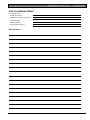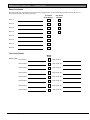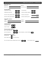
1
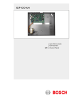
CC404
Operators Guide
EN
Solution 844
CC404 | Operators Guide | Copyright Notice
Copyright Notice
New Zealand Telepermit Notes
Unless otherwise indicated, this publication is the
copyright of Bosch Security Systems Pty Ltd
(“Bosch”). All rights are reserved.
The grant of a telepermit for a device in no way
indicates Telecom acceptance of responsibility for the
correct operation of that device under all operating
conditions.
You may download a single copy of this publication.
By downloading the publication you agree that you
will: (i) only use the publication for your own
reference; (ii) not commercially exploit or charge any
person for the use of the publication; and (iii) not
modify the publication in any way without the prior
written permission of Bosch.
Except as specified above or where authorised by the
Copyright Act 1968 (Cth), no part of this publication
may be reproduced, transmitted, modified or stored,
in any form or by any means, without the prior
written permission of Bosch.
This equipment will not be used in any manner that
could constitute a nuisance to other telecom
customers.
Immediately disconnect this equipment should it
become physically damaged and arrange for its
disposal or repair.
Notice of Liability
The transmit level from this device is set at a fixed
level and because of this, there may be circumstances
where the performance is less than optimal. Before
reporting such occurrences as faults, please check the
line with a standard telepermitted telephone and do
not report a fault if the telephone performance is
satisfactory.
This material is designed for use by tradespeople with
expertise in the installation of this product. Persons
without appropriate expertise should seek assistance
before attempting installation.
This device is equipped with pulse dialling while the
Telecom standard is DTMF tone dialling. There is no
guarantee that Telecom lines will always continue to
support pulse dialling.
While care was taken in the preparation of this
material, Bosch Security Systems Pty Ltd and its
representatives are not responsible to any person or
entity for any loss or damage directly or indirectly
caused by information in, or any omission from, this
material.
Use of dialling, when this equipment is connected to
the same line as other equipment, may give rise to
bell noise and also cause a false answer condition.
Should such problems occur, the user should not
contact the Telecom Faults Service.
Bosch Security Systems Pty Ltd reserves the right to
make changes to features and specifications of its
products at any time without prior notification.
This equipment is set up to carry out test calls at predetermined times. Such test calls interrupt any other
calls that may be set up on the line at the same time.
The timing set for such test calls should be discussed
with the installer.
The timing set for test calls from this equipment may
be subject to drift. If this proves to be inconvenient
and your calls are interrupted, then the problem of
timing should be discussed with the equipment
installer. The matter should not be reported as a fault
to Telecom Faults Service.
This equipment shall not be set up to make automatic
calls to the Telecom 111 Emergency Service.
This equipment should not be used under any
circumstances that may constitute a nuisance to other
Telecom customers.
In the event of any problem with this device, the
systems battery, AC mains supply, and telephone line
should be disconnected. The user is to arrange with
the supplier of the device to make the necessary
repairs.
Should the matter be reported to Telecom as a wiring
fault and the fault proven to be due to this product, a
call-out charge will be incurred.
2
Bosch Security Systems | 7/05 | F01U009494B
CC404 | Operators Guide | Contents
Contents
1.0
2.0
3.0
3.1
3.2
3.3
3.4
3.5
3.6
3.7
3.8
3.9
4.0
4.1
4.2
4.3
4.4
5.0
6.0
6.1
6.2
6.3
7.0
8.0
8.1
8.2
8.3
8.4
8.5
9.0
9.1
9.2
10.0
11.0
11.1
11.2
11.3
12.0
12.1
12.2
13.0
14.0
15.0
16.0
16.1
16.2
16.3
16.4
Introduction.......................................................4
Features ..............................................................4
Codepad Indicators .........................................5
Zone Indicators ...................................................5
AWAY Indicator ................................................5
STAY Indicator...................................................5
System Disarmed ................................................5
MAINS Indicator................................................6
Off Indicator/Zone Sealed.................................6
On Indicator/Zone in Alarm.............................6
FAULT Indicator................................................6
Audible Indications ............................................6
Arming the System ..........................................6
Arming in AWAY Mode...................................7
Arming in STAY Mode 1..................................7
Arming in STAY Mode 2..................................7
Programming STAY Mode 2 Zones ................8
Disarming the System .....................................8
User Codes.........................................................8
Adding User Codes ............................................8
Adding Radio Remote User Codes..................8
Deleting User Codes/Radio User Codes .........8
Radio Transmitter Operations......................9
Alarms.................................................................9
Duress Alarm ......................................................9
Panic Alarm.........................................................9
Fire Alarm ...........................................................9
Medical Alarm ..................................................10
Tamper Alarm (Access Denied) .....................10
Isolating Zones................................................10
Standard Isolating.............................................10
Code to Isolate..................................................10
Setting the Date and Time ...........................10
Fault Analysis Mode ......................................11
AC Fail...............................................................11
System Faults.....................................................11
Fault Descriptions .............................................11
Telco Arm/Disarm Sequence (Call
Forward On/Off) ............................................12
Telco Arm Sequence........................................12
Telco Disarm Sequence ...................................12
Turning Outputs On/Off ..............................13
Reset Latching Outputs ................................13
Codepad ID/Buzzer Tone Change ............13
Testing ..............................................................13
Horn Speaker Test............................................13
Bell Test .............................................................13
Strobe Test.........................................................13
Walk Test Mode ...............................................13
Bosch Security Systems | 7/05 | F01U009494B
16.5
17.0
18.0
19.0
20.0
20.1
20.2
20.3
21.0
22.0
23.0
24.0
25.0
Test Report........................................................ 13
Event Memory Recall ................................... 14
Day Alarm ....................................................... 14
Remote Arming By Telephone................... 14
Domestic Dialling .......................................... 15
Acknowledging Domestic Calls...................... 15
Programming Domestic Telephone
Numbers ............................................................ 15
Disable Domestic Dialling............................... 15
Basic Pager Reporting................................... 16
SMS Reporting ............................................... 18
Glossary of Terms .......................................... 19
Installation Notes ........................................... 21
Specifications .................................................. 24
Figures
Figure 1:
Figure 2:
Figure 3:
Figure 4:
Figure 5:
Figure 6:
CP5 Eight Zone LED Codepad................. 5
CP5 Eight Zone LCD Codepad ................ 5
RE012E – 2 Channel Keyfob
Transmitter................................................... 9
RE013E – 4 Channel Keyfob
Transmitter................................................... 9
CP5 LED Codepad Showing Audible
Alarm Buttons.............................................. 9
Basic Pager Display................................... 17
Tables
Table 1:
Table 2:
Table 3:
Table 4:
Table 5:
Table 6:
Table 7:
Table 8:
Table 9:
Table 10:
Table 11:
Table 12:
Table 13:
Table 14:
Table 14:
Table 15:
Zone Indicators............................................ 5
AWAY Indicator......................................... 5
STAY Indicator ........................................... 5
MAINS Indicator ........................................ 6
FAULT Indicator ........................................ 6
Audible Indicators....................................... 6
Arming Methods ......................................... 6
Keyfob Audible and Visual Indications ... 9
Fault Condition Indicators ....................... 11
Telco Arm/Disarm Dialling Digits.......... 12
Domestic Dialling Telephone Digits....... 15
Zone Status Display Descriptions............ 16
System Status ............................................. 16
SMS Text Messages .................................. 18
Glossary of Terms ..................................... 19
Specifications ............................................. 24
3
CC404 | Operators Guide | 1.0
Introduction
1.0 Introduction
2.0 Features
Congratulations on selecting the Solution 844 Model
CC404 Control Panel to protect you and your
property. To get the most from your unit, read
through this manual and familiarise yourself with the
operating features of this system. In all aspects of
planning, engineering, styling, operation,
convenience, and adaptability, we have sought to
anticipate your every possible requirement.
The Solution 844 Control Panel uses the latest in
microprocessor technology to provide you with more
useful features, and superior reliability and
performance. The main features of the control panel
are:
• Eight programmable User Codes
• STAY Mode and AWAY Mode operation
• Four programmable burglary zones
• Four programmable 24-hour zones
• Siren and/or dialler lockout per zone
• Delayed reporting
• Built-in telephone fail monitor
• Day alarm
• Remote arming
• Answering machine bypass
• Event memory recall
• Upload/download programmable
• Auxiliary output (Output 2)
• Relay output
• Eight radio remote user codes
• Entry and exit warning beeper
• EDMSAT – satellite siren compatible
• Separate fire alarm sound
• Dual reporting
• Sensor watch
• Dynamic battery testing
• Automatic arming and disarming
• AC fail and system fault indicators
• Walk Test Mode
• Monitored siren output (Output 1)
• Strobe output
• Telco arm and disarm sequence (call forwarding)
Programming simplicity and speed were some of the
major considerations and we believe that our
objectives in this area were more than satisfied.
This guide explains all aspects of operating the
control panel. All system parameters and options are
detailed. Suitability is left up to the individual. Every
system can be tailored to meet all requirements
quickly and easily.
4
Bosch Security Systems | 7/05 | F01U009494B
CC404 | Operators Guide | 3.0
3.0 Codepad Indicators
3.2
Codepad Indicators
AWAY Indicator
The AWAY indicator shows the system
is armed in AWAY Mode. The AWAY
indicator also flashes in unison with the
STAY indicator when programming
the control panel.
Figure 1: CP5 Eight Zone LED Codepad
Refer to Section 4.1 Arming in AWAY
Mode on page 7 for information on the
different methods of arming the system
in AWAY Mode.
Table 2: AWAY Indicator
Figure 2: CP5 Eight Zone LCD Codepad
Status
Definition
On
Off
System is armed in AWAY Mode.
System is not armed in AWAY Mode.
3.3
STAY Indicator
The STAY indicator shows the system is
armed in STAY Mode 1 or STAY
Mode 2. The STAY indicator also flashes
in unison with the AWAY indicator when
programming the control panel.
The codepad is the communications interface
between you and your alarm system. Use the
codepad to issue commands. The codepad offers
both visual and audible indications that guide you
through general operation.
The codepad incorporates a number of indicators.
Eight zone indicators show the status of each zone
and four other indicators show general status.
3.1
Refer to Section 4.2 Arming in STAY Mode
1 on page 7 and Section 4.3 Arming in
STAY Mode 2 on page 7.
Table 3: STAY Indicator
Status
Definition
On
System is armed in STAY Mode
1 or STAY Mode 2.
System is not armed in STAY
Mode 1 or STAY Mode 2.
Zone Isolating Mode or setting
STAY Mode 2 zones.
Day alarm status – day alarm
turned on.
Off
Zone Indicators
1 2 3 …. The zone indicators (1 to 8) display
the status of the zones. Table 1 lists the
status that the indicators display (such
as, Zone Sealed/Zone Unsealed).
Flashing twice a
second
Flashing once every
3 seconds
3.4
Table 1: Zone Indicators
Status
Definition
On
Off
Flashing fast
(0.25 sec on/
0.25 sec off)
Flashing slow
(1 sec on/1 sec off)
Zone is unsealed.
Zone is sealed.
Zone is in alarm.
System Disarmed
This indicator and the
indicator light
when the system is disarmed.
Zone is manually isolated or
selected to be isolated.
Bosch Security Systems | 7/05 | F01U009494B
5
CC404 | Operators Guide | 4.0
3.5
Arming the System
MAINS Indicator
The MAINS indicator shows if the
systems AC mains supply is normal or
failed.
Table 6: Audible Indicators
Indicator
Definition
One short beep
A button was pressed on the
codepad, or end of exit time
occurred when armed in STAY
Mode 1 or STAY Mode 2.
The system accepted your code.
The system executed the requested
function.
Indicates the end of exit time when
armed in AWAY Mode, or the
requested operation was denied or
aborted.
Walk Test Mode is currently active
or it is a warning before automatic
arming takes place.
There is a system fault waiting to be
acknowledged.
Table 4: MAINS Indicator
Status
Definition
On
Flashing
AC mains power normal.
AC mains supply failed.
3.6
On Indicator/Zone in Alarm
The
indicator lights when the
system is armed in AWAY Mode and
flashes when an alarm occurs. The
system resets this indicator after you
enter a valid user code.
3.8
FAULT Indicator
The FAULT indicator lights if the
system detects a system fault. Refer to
Section 11.0 Fault Analysis Mode on
page 11 for additional information on
system faults.
Every time a new system fault is
detected (the FAULT indicator flashes),
the codepad beeps once every minute.
Pressing [#] once cancels the once a
minute beep and acknowledges the
fault (the FAULT indicator lights
steadily).
Table 5: FAULT Indicator
Indicator
Definition
On
Off
Flashing
There is a system fault you must correct.
The system is normal. There are no faults.
There is a system fault that must be
acknowledged.
3.9
One beep every
second
One short beep
every minute
4.0 Arming the System
There are several ways to arm the system depending
on whether you are:
• Leaving the premises and you want all active
zones to be in a ready state for an intruder.
• Remaining in the premises and you only want
part of the system to be in a ready state for an
intruder.
If a zone is not sealed at the end of exit time, the
zone is automatically isolated and lights steadily on
the remote codepad. The zone becomes an active
part of the system when the zone is resealed. For
example, if a window is left open after exit time
expires, the window is not an active part of the
system until the window is closed. Opening the
window after exit time expires causes an alarm.
Table 7 defines the different methods for arming the
system.
Table 7: Arming Methods
Method
Definition
AWAY Mode
Arms the entire system. Refer to
Section 4.1 Arming in AWAY Mode.
Arms all zones except those
programmed by the installer to be
automatically isolated. Refer to Section
4.2 Arming in STAY Mode 1.
Arms all zones except those
programmed by the Master Code
holder to be automatically isolated.
Refer to Section 4.3 Arming in STAY
Mode 2.
STAY Mode 1
Audible Indications
Table 6 defines the audible indicators generated by
the codepad buzzer.
6
One long beep
Off Indicator/Zone Sealed
The
indicator lights when the
system is disarmed and flashes when a
zone becomes unsealed when
disarmed. The indicator stops flashing
when all zones are sealed.
3.7
Two short beeps
Three short beeps
STAY Mode 2
Bosch Security Systems | 7/05 | F01U009494B
CC404 | Operators Guide | 4.0
Forced Arming
Arming the system when a zone is not sealed is
known as forced arming. If the system is not armed
and a long beep sounds, forced arming is not
permitted. If this is the case, ensure that all zones are
sealed or manually isolated before arming the system.
4.1
Arming in AWAY Mode
When you leave your premises and require all zones
to be in a ready state to detect intrusion, arm the
system in AWAY Mode. When returning to your
premises, disarm your system (see Section 5.0
Disarming the System) so you do not sound a false
alarm.
There are two different methods for arming the
system in AWAY Mode. One method is standard
and is always available. The other method is optional
and might be disabled by your installer.
To arm in AWAY Mode using the first method:
Enter your user code and press [#] (for example,
[2 5 8 0 #]).
Two beeps sound and the AWAY indicator lights.
Exit time starts.
To arm in AWAY Mode using the second
method:
Hold down [#] until two beeps sound.
The AWAY indicator lights and exit time starts.
4.2
Arming in STAY Mode 1
STAY Mode 1 is only used when the perimeter and
unused areas of the premises must be armed to detect
if an intruder is entering the premises. At the same
time, it allows you to move freely within an area that
is automatically isolated.
Only your security company can
program zones automatically isolated in
STAY Mode 1.
There are two different methods for arming the
system in STAY Mode 1. One method is standard
and is always available. The other method is optional
and might be disabled by your installer.
Entry Guard Timer for STAY Mode 1
When arming the system in STAY Mode 1, an
optional entry timer called Entry Guard Timer for
STAY Mode 1 is available. Use this entry timer to
delay the sirens if a zone is not automatically isolated
and activates an alarm. Entry Guard Timer for STAY
Mode 1 is the delay time used for all zones except
24-hour zones when the system is armed in STAY
Mode 1 or STAY Mode 2.
Bosch Security Systems | 7/05 | F01U009494B
Arming the System
If the Entry Guard Timer for STAY Mode 1 is
programmed and a zone not automatically isolated is
activated, the codepad beeps twice per second until
the entry timer expires or the system is disarmed. If
the alarm condition is not reset by entering your user
code and pressing [#] (for example, [2 5 8 0 #])
before the entry timer expires, the sirens sound an
alarm. Only your installer can program this feature.
To arm in STAY Mode 1 using the first method:
Enter your user code and press [*] (for example,
[2 5 8 0 *]).
Two beeps sound and the STAY indicator lights. Exit
time starts counting.
Any zones programmed to be automatically isolated
in STAY Mode 1 flash until exit time expires. At the
end of exit time, all zones selected to be
automatically isolated turn off and the codepad gives
one short beep.
To arm in STAY Mode 1 using the second
method:
Hold down [*] until two beeps sound.
The STAY indicator lights and exit time starts.
Any zones programmed to be automatically isolated
in STAY Mode 1 flash until exit time expires. At the
end of exit time, the zone indicators turn off and the
codepad sounds one short beep.
4.3
Arming in STAY Mode 2
STAY Mode 2 is used only when you want to arm
the perimeter and unused areas of the premises to
detect an intruder while you move freely within an
automatically isolated area. Any Master Code user
can program zones to be automatically isolated in
STAY Mode 2.
Entry Guard Timer for STAY Mode 2
When arming the system in STAY Mode 2, an
optional entry timer called Entry Guard Timer for
STAY Mode 2 is available. Use this entry timer to
delay the sirens if a zone is not automatically isolated,
but activates an alarm. Entry Guard Timer for STAY
Mode 2 is the delay time used for all zones, except
24-hour zones, when the system is armed in STAY
Mode 1 or STAY Mode 2.
If the Entry Guard Timer for STAY Mode 2 is
programmed and a zone not automatically isolated
activates an alarm, the codepad beeps twice a second
until the entry timer expires or you disarm the
system. If you do not reset the alarm by entering
your user code and pressing [#] (for example,
[2 5 8 0 #]) before the entry timer expires, the system
activates the sirens to sound an alarm. Only your
installer can program this option.
7
CC404 | Operators Guide | 5.0
Disarming the System
To arm in STAY Mode 2:
Hold down [0] until two beeps sound.
The STAY indicator lights and exit time starts.
Any zones programmed to be automatically isolated
in STAY Mode 2 flash until exit time expires. At the
end of exit time, the indicators turn off for all zones
selected to be automatically isolated and the codepad
sounds one short beep.
4.4
Programming STAY Mode 2 Zones
If you have a Master Code, you can only program
zones to be automatically isolated in STAY Mode 2.
How to Program STAY Mode 2 Zones
1. Enter your four-character Master Code and press
[4 #] key (for example, [2 5 8 0 4 #]).
Three beeps sound and the STAY indicator
flashes.
2. Enter the zone number to automatically isolate
and press [*] (for example, [1 *] for Zone 1 or
[2 *] for Zone 2).
The selected zone flashes.
If you make a mistake, enter the same zone
number and press [#] to clear the incorrect zone.
To select additional zones to automatically isolate
in STAY Mode 2, repeat Step 2 as many times as
necessary.
3. After you select the zones to automatically isolate
in STAY Mode 2, press [#] to exit this mode.
Two beeps sound and the STAY and AWAY
indicators turn dark.
5.0 Disarming the System
When you enter the premises after the system is
armed in AWAY Mode, or if you armed the system
in STAY Mode 1 or STAY Mode 2, you must disarm
the system before entry time expires to disable
detection devices that activate an alarm. Only your
installer can program the entry time.
If there was an alarm before you disarm the system, a
flashing zone indicator shows a previous alarm on
that zone.
To disarm the system:
Enter your user code and press [#] key (for example,
[2 5 8 0 #]).
Two beeps sound.
6.0 User Codes
6.1
Adding User Codes
Only the Master Code holder can add or change
other system user codes, including the Master Code.
The Master Code holder can program up to eight
user codes for the system.
8
To add a user code:
1. Enter your four-character Master Code and press
[1 #] (for example, [2 5 8 0 1 #]).
Three beeps sound and the STAY and AWAY
indicators flash.
2. Enter the user code number (1 to 8) and press [#]
(for example, [2 #] for User 2, or [8 #] for
User 8).
Two beeps sound and the selected user number
appears on the codepad indicators.
3. Enter the digits required for the new code and
press [#] (for example, for user code 5768, enter
[5 7 6 8 #]).
Two beeps sound and the STAY and AWAY
indicators turn off.
To add or change other user codes, repeat this
procedure as many times as necessary.
6.2
Adding Radio Remote User Codes
Only the Master Code holder can add or change
other system user codes, including the Master Code.
The Master Code holder can program up to eight
radio user codes (User Codes 9 to 16) for the system.
To add a radio remote user code:
1. Enter your four-character Master Code and press
[1 #] (for example, [2 5 8 0 1 #]).
Three beeps sound and the STAY and AWAY
indicators flash.
2. Enter the radio remote user code number
(9 to 16) and press [#] (for example, [9 #] for
User 9, or [1 6 #] for User 16).
Two beeps sound and the selected user number
appears on the codepad indicators.
3. Press any button on the keyfob so the system
learns the ID number. Two beeps sound and the
STAY and AWAY indicators turn off.
To add or change other radio remote user codes,
repeat this procedure as many times as required.
6.3
Deleting User Codes/Radio User
Codes
Only the Master Code holder can delete other
system user codes.
To delete a user code:
1. Enter your four-character Master Code and press
[1 #] (for example, [2 5 8 0 1 #]).
Three beeps sound and the STAY and AWAY
indicators flash.
2. Enter the user code number (User Code 1 to 8,
or Radio User Code 9 to 16) and press [#] (for
example, [2 #] for User 2, [1 6 #] for User 16).
Two beeps sound and the selected user number
appears on the codepad indicators.
3. Press the [*] key to delete the selected user code.
Two beeps sound and the STAY and AWAY
indicators turn off. To delete other user codes,
repeat this procedure as many times as required.
Bosch Security Systems | 7/05 | F01U009494B
CC404 | Operators Guide | 7.0
7.0
Table 8: Keyfob Audible and Visual Indications
Radio Transmitter
Operations
Figure 3: RE012E – 2 Channel Keyfob
Transmitter
1
Radio Transmitter Operations
2
Indication
Definition
One beep
Two beeps
Two-tone beep
3-sec strobe
6-sec strobe
System disarmed.
System armed in AWAY Mode.
System armed in STAY Mode.
System disarmed.
System armed in AWAY or STAY
Mode.
8.0 Alarms
8.1
3
1 – Button 1: Arm or disarm in AWAY Mode
2 – Button 2: Arm or disarm STAY Mode
3 – Buttons 1 and 2: Press both buttons at the
same time to activate Panic alarm.
Figure 4: RE013E – 4 Channel Keyfob
Transmitter
1
Duress Alarm
A codepad duress alarm is used as a silent hold-up
alarm. This only occurs when a user adds 9 to the
end of a valid user code when disarming the system
(for example, [2 5 8 0 9 #]). A duress alarm is only
useful if your system reports back to a monitoring
station or pocket pager, because domestic reporting
(such as a mobile phone) cannot decipher which type
of alarm occurred.
Figure 5: CP5 LED Codepad Showing Audible
Alarm Buttons
3
2
4
1 – Button 1: Arm or disarm in AWAY Mode
2 – Button 2: Arm or disarm in STAY Mode
3 – Buttons 1 and 2: Press both buttons at the
same time to activate Panic alarm.
4 – Buttons 3 and 4: Your security company
can program these buttons for optional
operation, such as operating a garage door.
Audible and Visual Indications
When using hand-held keyfob transmitters to operate
the system, your security company can program the
keyfobs to sound the horn speaker or operate the
blue strobe light. These indications allow you to
operate the system from outside the premises with
confidence.
8.2
Panic Alarm
An audible alarm activates when you press [1] and [3]
or [*] and [#] simultaneously. Contact your installer
to disable the ability to activate the codepad panic
alarm or to silence the codepad panic alarm.
8.3
Fire Alarm
The horn speaker emits a distinct fire sound when
you press [4] and [6] simultaneously. Contact your
installer to disable the ability to activate the codepad
fire alarm or to silence the codepad fire alarm.
Bosch Security Systems | 7/05 | F01U009494B
9
CC404 | Operators Guide | 9.0
8.4
Isolating Zones
Medical Alarm
9.2
Code to Isolate
An audible alarm activates when you press [7] and [9]
simultaneously. Contact your installer to disable the
ability to activate the codepad medical alarm or to
silence codepad medical alarm.
Only the user codes with the Code to Isolate priority
level can isolate zones. If any user code has this
priority level, the standard isolating method (refer to
Section 9.1 Standard Isolating) does not function.
8.5
To isolate a zone:
1. Press [*], enter your user code, and press [*]
again to enter Isolating Mode (for example,
[* 2 5 8 0 *]).
Three beeps sound and the STAY indicator
flashes.
2. Enter the zone number (1 to 8) and press [*] (for
example, [1 *] for Zone 1 or [2 *] for Zone 2).
Each zone to isolate has a corresponding zone
indicator that flashes. If you selected an incorrect
zone to isolate, enter the incorrect zone number
again and press [*].
If you are isolating more than one zone, repeat
Step 2 until you select the zones you want to
isolate.
3. Press [#] after all selected zones are isolated.
Two beeps sound and the system returns to the
disarmed state.
Tamper Alarm (Access Denied)
The tamper alarm restricts the number of times
someone can attempt to use an invalid user code to
operate the system. When the number of incorrect
code attempts equals the number programmed by
your installer, the system activates an alarm. If
reporting back to a security monitoring station, the
system sends an Access Denied Report.
To shut down and lock out a codepad for a period of
time (0 to 150 seconds), ask your installer to program
this feature.
9.0 Isolating Zones
Isolating zones allow you to manually disable one or
more zones before arming the system. Once a zone is
isolated, you can access that zone during the armed
state without activating an alarm.
For example, you might need to isolate a zone
because before arming the system a PIR detector
might generate a false alarm, or you need to leave a
pet inside a particular zone while away.
Isolating zones is performed by one of two methods.
The second method is optional and only allows those
user codes programmed by your installer access to
isolate zones.
9.1
Standard Isolating
Standard isolating allows all operators to isolate zones
without knowing a valid user code.
To isolate a zone:
1. Press [*] twice to enter Isolating Mode.
Three beeps sound and the STAY indicator
flashes.
2. Enter the zone number (1 to 8) and press [*] (for
example, [1 *] for Zone 1, or [2 *] for Zone 2).
Each zone to isolate has a corresponding zone
indicator that flashes.
If you selected an incorrect zone to isolate, enter
the incorrect zone number again and press [*].
Repeat Step 2 if you are isolating more than one
zone, until all zones you want to isolate are
selected.
3. Press [#] after you isolate all selected zones.
Two beeps sound and the system returns to the
disarmed state.
10
10.0 Setting the Date and Time
Programming the date and time is only required
when you need functions such as automatic test
reports, automatic arming, and history events to
operate correctly.
To program the date and time:
1. Enter your Master Code and press [6 #] (for
example, [2 5 8 0 6 #]).
Three beeps sound and the STAY and AWAY
indicators flash.
2. Enter the day, month, year, hour, and minute
using the (DD, MM, YY, HH, MM) format (that
is, DD = day of the month, MM = month of the
year, YY = current year, HH = hour of the day,
MM = minute of the day).
When programming the hour of the day,
you must use a 24-hour format.
3.
Press [#] to exit and return to the disarmed state.
Two beeps sound and the STAY and AWAY
indicators turn off. A long beep sounds if you
incorrectly entered the date and time.
Bosch Security Systems | 7/05 | F01U009494B
CC404 | Operators Guide | 11.0
Fault Analysis Mode
Sensor Watch Fail
11.0 Fault Analysis Mode
If a fault occurs, the FAULT or MAINS indicators
flash and the codepad beeps once every minute.
11.1
AC Fail
A sensor watch fault registers because one or more
detection devices failed to notice any movement
during the disarmed state for the time period
programmed by your installer. The fault clears when
the zone in question detects movement and is reset.
If the AC mains supply fails, the MAINS indicator
flashes until the AC mains supply is restored.
Pressing [#] once acknowledges the fault and stops
the codepad from beeping once every minute.
While in Fault Analysis Mode, hold down [5] until
two beeps sound.
The indicator corresponding to the faulted zone
lights.
11.2
Horn Speaker Fail
System Faults
To determine all system faults other than the AC
mains supply, enter Fault Analysis Mode:
1. Hold down [5] until two beeps sound.
The FAULT indicator lights steadily and the
STAY and AWAY indicators flash in unison.
Any lit zone indicators indicate the type of fault
that occurred. See Table 9 for the list of system
faults that can occur.
2. To further determine the type of fault condition,
hold down the key that corresponds to the lit
zone indicator.
3. To exit Fault Analysis Mode and return to the
disarmed state, press [#].
The FAULT indicator remains lit and the
codepad stops beeping once per minute.
A horn speaker failure fault registers when the system
detects the horn speaker is disconnected. This fault
clears once the horn speaker is reconnected. Your
installer must program the system for this feature to
operate.
11.3
Fuse Fail
Fault Descriptions
Table 9: Fault Condition Indicators
Zone LED
1
2
3
4
5
6
7
8
FAULT Condition
Battery Fail
Date/Time
Sensor Watch
Horn Speaker Fail
Telephone Line Fail
E2 Fault
Fuse Fail
Communication Fail
Telephone Line Fail
A telephone line failure fault registers when the
system detects the telephone line is disconnected
from the control panel. Your installer must program
the system for this feature to operate.
E2 Fault
An E2 failure fault registers when the system detects
an internal checksum error. Contact your installer if
this fault occurs.
A fuse failure fault occurs when either of the two 1 A
fuses are blown. Contact your installer if this fault
occurs.
Communication Fail
A communication fail fault registers when the control
panel fails to communicate with the receiving party
(for example, a monitoring company, mobile phone,
pocket pager, and so on). The communication fault
clears after the control panel successfully reports to
the receiving party.
Battery Fail
A battery fail fault registers when the system detects a
low capacity backup battery. The system
automatically performs a Battery Test every 4 hours
and every time the system is armed.
Date and Time
The date and time fault registers every time the
system powers down. This type of fault does not
cause the FAULT indicator to display on the
codepad unless your installer programmed the
automatic arming time. Refer to Section 10.0 Setting
the Date and Time to program the date and time.
Bosch Security Systems | 7/05 | F01U009494B
11
CC404 | Operators Guide | 12.0
Telco Arm/Disarm Sequence (Call Forward On/Off)
4.
12.0 Telco Arm/Disarm
Sequence (Call Forward
On/Off)
12.1
Press [#] when finished.
Two beeps sound, and the STAY and AWAY
indicators turn off.
To disable the Telco Arm Sequence,
enter the call forward sequence as [* 4]
(break) for Step 3.
Telco Arm Sequence
Use this section to program the Call Forward –
Immediate On sequence or Call Forward – No
Answer sequence to automatically operate when you
arm the system in AWAY Mode. This feature is only
available if your telecommunications provider has the
call-forward option.
The examples given in this feature are
only applicable to Australia.
Call Forward – Immediate On
You can redirect calls to anywhere in Australia,
including mobile phones, pagers, and answering
services. When Call Forward is turned on, your
telephone does not ring.
Call Forward – No Answer
If your telephone is not answered within 20 sec, this
feature redirects all incoming calls to another number
anywhere in Australia. When this feature is enabled,
you can still make outgoing calls.
Table 10: Telco Arm/Disarm Dialling Digits
Digit
Required
0
1
2
3
4
5
6
7
Number to
Program
0
1
2
3
4
5
6
7
Digit
Required
8
9
*
#
4-sec pause
break
12.2
Telco Disarm Sequence
This feature automatically disables the call forward
sequence when disarming the system.
To program the Telco Disarm Sequence:
1. Enter your four-character Master Code and press
[3 #] (for example, [2 5 8 0 3 #]).
Three beeps sound and the STAY and AWAY
indicators flash.
2. Press [2 #] to select the Telco Disarm Sequence.
Three beeps sound.
3. Enter the call forward disable sequence (for
example, [# 6 1 #] to disable the No Answer
Call Forward sequence, or [# 2 1 #] to disable
the Call Forward Immediate sequence).
To program a “#” in the Telco Disarm Sequence,
enter [* 2].
4. Press [#] when finished.
Two beeps sound, and the STAY and AWAY
indicators turn off.
To disable the Telco Disarm Sequence,
enter the call forward sequence as [* 4]
(break) for Step 3.
Number to
Program
8
9
*1
*2
*3
*4
To program the Telco Arm Sequence:
1. Enter your four-character Master Code and press
[3 #] (for example, [2 5 8 0 3 #]).
Three beeps sound and the STAY and AWAY
indicators flash.
2. Press [1 #] to select the Telco Arm Sequence.
Three beeps sound.
3. Enter the call forward sequence (for example,
[* 6 1][Phone Number][#] to program the Call
Forward - No Answer sequence, or [* 2 1][Phone
Number][#] to program the Call Forward
Immediate sequence).
To program a “*” in the Telco Arm Sequence,
enter [* 1]. To program a “#” in the Telco Arm
Sequence, enter [* 2].
12
Bosch Security Systems | 7/05 | F01U009494B
CC404 | Operators Guide | 13.0
Turning Outputs On/Off
13.0 Turning Outputs On/Off
16.0 Testing
This feature only applies if your installer set up an
output to be turned on or off by the codepad. Your
installer can program up to three outputs to control a
pool pump, outside lighting, and so on.
There are five functions for testing that your system
operates correctly.
To turn an output on or off:
1. Enter your Master Code and press [5 #] (for
example, [2 5 8 0 5 #]).
Three beeps sound and the STAY and AWAY
indicators flash.
2. Enter the output number (1 to 3) you want to
turn on or off.
3. Press [#] to turn the output on, or press [*] to
turn the output off.
Three beeps sound if you turn the output on, and
two beeps sound if you turn the output off.
Repeat Step 2 and Step 3 to turn other outputs
on or off.
4. Press [#] to exit this function.
Two beeps sound and the STAY and AWAY
indicators turn off.
14.0 Reset Latching Outputs
This feature only applies if your installer
programmed an output to latch (remain on) until you
acknowledge the event that turned on the output.
To reset latching outputs:
Hold down [7] until two beeps sound. The output
resets.
15.0 Codepad ID/Buzzer Tone
Change
Hold down [8] continuously to change the tone of the
codepad buzzer.
There are 50 different tones, from 1500 Hz to
5000 Hz. If multiple codepads are installed, each
codepad can sound a different tone.
Bosch Security Systems | 7/05 | F01U009494B
16.1
Horn Speaker Test
Press and hold [1] until two beeps sound.
The horn speaker sounds for 2 sec.
16.2
Bell Test
Press and hold [2] until two beeps sound.
The bell output turns on for 2 sec.
16.3
1.
2.
Strobe Test
Press and hold [3] until three beeps sound.
The strobe flashes.
Press and hold [3] until two beeps sound.
The strobe stops flashing.
16.4
Walk Test Mode
Use Walk Test Mode to test the proper operation of
detection devices. Every time you test a zone, the
codepad sounds one long beep and the horn speaker
sounds one short beep to indicate the zone was
activated when testing.
1. Enter your four-character Master Code and press
[7 #] (for example, [2 5 8 0 7 #]).
Three beeps sound, and the STAY and AWAY
indicators flash. The codepad beeps once per
second while the system is in Walk Test Mode.
2. Activate the zones you want to test.
The codepad sounds one long beep and the horn
speaker sounds one short beep each time a zone
is faulted (unsealed) and restored.
3. When you finish testing the zones, press [#] to
exit this mode.
Two beeps sound, and the STAY and AWAY
indicators turn off. The system returns to the
disarmed state.
16.5
Test Report
This feature only applies if your system reports by
telephone. Press and hold [9] until two beeps sound.
The system sends a Test Report without sounding the
sirens.
13
CC404 | Operators Guide | 17.0
Event Memory Recall
17.0 Event Memory Recall
Use this function to replay the last 40 system events
that occurred. The event memory history replays all
alarms, and arming and disarming of the system in
AWAY Mode, STAY Mode 1, and STAY Mode 2.
The system cannot differentiate between
arming the system in STAY Mode 1 or
STAY Mode 2.
To enter Event Memory:
Enter your four-character Master Code and press
[8 #] (for example, [2 5 8 0 8 #]).
Three beeps sound. The last 40 events appear one at
a time by the codepad indicators, starting from the
most recent event. A beep sounds as each event
appears.
18.0 Day Alarm
Day alarm allows the system to monitor a
combination of zones when the system is disarmed
by beeping the codepad buzzer. Only your installer
can program Zones 1 to 4 to operate for day alarm.
Example
You can set up a day alarm at the front door of a
shop with a pressure mat or electronic beam that
customers activate as they enter and exit the shop. As
the customers walk onto the pressure mat or break
the electronic beam, the codepad buzzer beeps.
To turn day alarm on:
Hold down [4] until three beeps sound.
Day alarm turns on. If a zone programmed for day
alarm operation is activated when the system is
disarmed, the codepad beeps.
19.0 Remote Arming By
Telephone
Use this feature to arm your system by telephone
from any remote location. For security reasons, you
cannot disarm the system using this method. This
feature requires a touch-tone telephone. Remote
arming works only if your installer programmed this
feature.
To arm your system remotely by telephone:
1. Call the telephone number connected to your
control panel.
When the control panel answers the incoming
call, a short jingle sounds.
2. To arm the system, press [*] on the touch-tone
telephone for 1 to 3 sec.
If you hear modem tones when the control panel
answers the incoming call, the system is
programmed for remote programming functions
by your installer. Wait for a pause between the
tones before you press [*].
After you release [*] on the touch-tone telephone,
two beeps sound. The system is armed in AWAY
Mode.
3. Hang up the telephone.
The system remains armed.
If your installer programmed answering
machine bypass, you must call the control
panel twice to connect to the system. For
example, call the telephone number for the
control panel, let the call ring no more
than four times, and then hang up the
telephone. Wait at least 8 sec and call the
control panel again.
To turn day alarm off
Hold down [4] until two beeps sound.
Day alarm turns off.
14
Bosch Security Systems | 7/05 | F01U009494B
CC404 | Operators Guide | 20.0
20.0 Domestic Dialling
Domestic dialling enables the control panel to call
your mobile phone or a relative or friend if the
system detects an alarm. You can program up to
three different telephone numbers to call when an
alarm occurs. Although only your installer can set the
system to report in the domestic format, the Master
Code holder can change the domestic telephone
numbers at any time.
20.1
Acknowledging Domestic Calls
If an alarm occurs, the system calls the first
programmed telephone number. When you answer
an incoming call, the system sounds a repeating siren
tone followed by a pause, continuously for 2 min (for
example, siren tone, pause, siren tone, and pause).
If you do not acknowledge the call from the control
panel during a pause between siren tones, the control
panel hangs up after 2 min, and calls the next
telephone number.
Press [*] for 1 to 3 sec during the pause to
acknowledge the call.
If you acknowledge the call, the control panel does
not call any more phone numbers for that event. If
the call is successfully acknowledged, a tone of
decreasing pitch sounds.
Table 11: Domestic Dialling Telephone Digits
Digit
Required
0
1
2
3
4
5
6
7
20.2
Number to
Program
0
1
2
3
4
5
6
7
Digit
Required
8
9
*
#
4-sec pause
break
Number to
Program
8
9
Domestic Dialling
To program telephone numbers:
1. Enter your four-character Master Code and press
[2 #] (for example, [2 5 8 0 2 #]).
Three beeps sound and the STAY and AWAY
indicators flash.
If there are telephone numbers already
programmed, the numbers appear one digit at a
time by the codepad indicators.
If there are no telephone numbers programmed,
another two beeps sound after entering this
mode. These two beeps are normally heard after
the last digit of the last telephone number
appears.
2. Enter the first telephone number (for example,
[9 6 7 2 1 7 1 7]).
As you enter each digit, the corresponding
codepad indicators light.
3. To program another telephone number, press
[* 4] and repeat Step 2.
This inserts a break between the first telephone
number and the second telephone number.
4. Press [#] to exit this function.
20.3
Disable Domestic Dialling
To suspend domestic dialling (for example, you are
moving and do not want the system to continue
calling your mobile phone):
1. Enter your four-character Master Code and press
[2 #] (for example, [2 5 8 0 2 #]).
Two beeps sound and the STAY and AWAY
indicators flash.
2. Press [* 4 #].
The STAY and AWAY indicators turn off.
*1
*2
*3
*4
Programming Domestic Telephone
Numbers
If your system is configured for domestic dialling, the
Master Code holder can program the telephone
numbers the control panel calls if an alarm occurs.
Bosch Security Systems | 7/05 | F01U009494B
15
CC404 | Operators Guide | 21.0
Basic Pager Reporting
21.0 Basic Pager Reporting
This feature only applies if your system reports to a
pocket pager. Basic pager reporting requires some
interpretation of the numbers that appear on the
display. It is possible to differentiate between 1000
different systems when a number of control panels
report to the one pocket pager.
Subscriber ID Number
This is the identification number of the control panel.
Only your installer can program this number.
Zone Status
The zone status display shows the status of each zone
(1 to 8). Table 12 describes each number of the zone
status display.
Table 12: Zone Status Display Descriptions
Display
0
1
2
3
Zone Description
Normal. The corresponding zone is sealed.
Alarm. The corresponding zone is unsealed
and in alarm.
Bypassed. A system operator manually
isolated the corresponding zone. Refer to
Section 9.0 Isolating Zones for information
about manually isolating a zone(s) before
arming the system.
Trouble. A zone was unsealed when exit time
expired.
System Status
The system status information is divided into the four
digits identified in Table 13.
Table 13: System Status
Digit
Description
First
8 = the system is disarmed
9 = the system is armed
Identifies the codepad alarm activated by the
operator:
0 = No Codepad Alarm
1 = Codepad Panic or Duress Alarm
2 = Codepad Fire Alarm
3 = Codepad Medical Alarm
0 = AC Supply is normal
1 = AC Supply failed
0 = System Normal – There are no faults.
1 = System Fault – The control panel
registered a fault.
Second
Third
Fourth
Figure 6 shows a transmission from a control panel
with an ID number of 678, and Zone 2 in alarm.
Figure 6 also shows Zone 3 is manually isolated and
the system is armed.
16
Bosch Security Systems | 7/05 | F01U009494B
CC404 | Operators Guide | 21.0
Basic Pager Reporting
Figure 6: Basic Pager Display
2
1
1
678
2
3
4
5
6
7
8
01200000
3
9000
4
5
6
7
8
1–
2–
3–
4–
Subscriber ID number
Zone status
System status
0: Zone Normal
1: Alarm
2: Zone Bypassed
3: Zone Trouble
5 – 8: Disarmed
9: Armed
Bosch Security Systems | 7/05 | F01U009494B
6 – 0: Normal
1: Panic/Duress
2: Fire Alarm
3: Medical Alarm
7 – 0: AC Normal
1: AC Failure
8 – 0: System Normal
1: System Fault
17
CC404 | Operators Guide | 22.0
SMS Reporting
22.0 SMS Reporting
SMS Reporting is an optional feature that your
installer can add allowing your control panel to send
SMS text messages to your mobile phone.
The SMS messages for the possible alarm events are
listed in Table 14. The <Subscriber ID> text is a
number between 0000 and 9999 assigned by your
installer.
Table 14: SMS Text Messages
Alarm Event
SMS Text
Panic
Test
Closing User x1
Opening User x1
Alarm Zone 1
Restore Zone 1
Alarm Zone 2
Restore Zone 2
Alarm Zone 3
Restore Zone 3
Alarm Zone 4
Restore Zone 4
Alarm Zone 5
Restore Zone 5
Alarm Zone 6
Restore Zone 6
Alarm Zone 7
Fire
Restore Zone 7
Fire
Alarm Zone 8
Tamper
Restore Zone 8
Tamper
AC Fail
AC Restore
Medical
<Subscriber ID> Panic
<Subscriber ID> Test
<Subscriber ID> Close User y2
<Subscriber ID> Open User y2
<Subscriber ID> Alarm Zone 01
<Subscriber ID> Restore Zone 01
<Subscriber ID> Alarm Zone 02
<Subscriber ID> Restore Zone 02
<Subscriber ID> Alarm Zone 03
<Subscriber ID> Restore Zone 03
<Subscriber ID> Alarm Zone 04
<Subscriber ID> Restore Zone 04
<Subscriber ID > Alarm Zone 05
<Subscriber ID> Restore Zone 05
<Subscriber ID> Alarm Zone 06
<Subscriber ID> Restore Zone 06
<Subscriber ID> Fire Alarm Zone 07
Medical Restore
Fuse Fail
Fuse Reset
1
2
<Subscriber ID> Fire Restore
Zone 07
<Subscriber ID> Tamper Alarm
Zone 08
<Subscriber ID> Tamper Restore
Zone 08
<Subscriber ID> AC Fail
<Subscriber ID> AC Restore
<Subscriber ID> Medical Alarm
Zone 07
<Subscriber ID> Medical Restore
Zone 07
<Subscriber ID> Fuse Fail
<Subscriber ID> Fuse Fail
x = 1 to 16
y = 01 to 16
Bosch Security Systems | 7/05 | F01U009494B
CC404 | Operators Guide | 23.0
Glossary of Terms
23.0 Glossary of Terms
Table 15: Glossary of Terms
Term
24-Hour Zones
Alarm
Answering Machine
Bypass
Armed
Automatic Arming
Automatic Disarming
AWAY Mode
Codepad
Day Alarm
Detectors
Disarmed
Dynamic Battery
Testing
Entry Time or
Entry Delay
External Equipment
Forced Arming
Handover Delay
Remote Control
Isolating
Master Code
Monitoring Station
Panic Alarm
Sealed
Sensor Watch
Description
A monitored input programmed to activate an alarm, if violated, if the system is
armed or disarmed.
Your system is armed and one of the detection devices was violated. A 24-hour
zone (such as a smoke detector) can activate an alarm when your system is armed
or disarmed.
When answering machine bypass is used, you can connect to the system for
remote arming operations when there is an answering machine or facsimile machine
connected to the same telephone line.
The system is in a ready state to accept alarms.
The system is automatically armed in AWAY Mode or STAY Mode 1 at the same
time every day.
The system is automatically disarmed at the same time every day.
Used to arm your system when you leave your premises.
The device used to arm and disarm the system, and to execute other functions such
as adding and deleting system user codes.
Monitors a combination of zones when the system is disarmed.
Devices connected to your system that detect intrusion or fire, and activate an
alarm. Some forms of detection devices include passive infrared (PIR), smoke
detectors, photoelectric beams, reed switches, and vibration sensors.
A state in which the system does not accept alarms, except from zones
programmed for 24-hour operation.
Monitors and tests the condition of your backup battery.
The time allowed by a zone to disarm the system after you enter your premises.
Any devices connected to your system such as detectors, codepads, and sirens.
Enables you to arm your system even though one or more zones are unsealed.
The system is armed and a zone programmed for delay was violated. The delay zone
hands over the remaining delay time to a zone programmed as handover. The
handover zone does not activate an alarm until the remaining delay time expires. A
handover zone acts as an instant zone if it is violated before the delay zone.
Used to remotely operate your system using hand-held transmitters (keyfobs).
Manually disable (isolate) one or more zones before arming the system.
A code used to arm and disarm the system and to allow access to functions such
as adding and deleting user codes.
A secure location where a digital receiver monitors a number of alarm systems and
deciphers their Alarm Transmission Reports. The station operator can then advise
the appropriate authorities to take immediate action.
Type of alarm that indicates to the monitoring station there is an emergency
situation at your premises.
Refers to zone status. If a zone is sealed, the detection device is not violated and
the zone indicator is not lit on the codepad.
The ability of the control panel to recognise that detection devices might have
stopped working or that the view to a PIR detector is blocked (it is unable to detect
any movement during the time programmed by your installer).
Bosch Security Systems | 7/05 | F01U009494B
19
CC404 | Operators Guide | 23.0
Glossary of Terms
Table 15: continued
Term
Silent Alarm
STAY Mode 1
STAY Mode 2
Telco Arm Sequence
Telco Disarm
Sequence
Unsealed
User Code
Zones
Description
Your installer can program zones for silent operation. When the zone programmed
for silent operation is violated during the armed period, your alarm system
communicates with the monitoring station without sounding the sirens.
The system automatically isolates zones when you arm the system in STAY Mode 1.
Only your installer can program zones to be isolated automatically in this mode.
The system automatically isolates zones when you arm the system in STAY Mode 2.
Only the Master Code holder can program zones to be isolated automatically in this
mode.
Telco arming automatically diverts your telephone number to another telephone
when the system is armed in AWAY Mode. In Australia, this feature is called “Call
Forward”.
Telco disarming automatically calls the telephone exchange and does not forward
your telephone number.
Refers to zone status. A zone is unsealed when a zone is violated. The
corresponding zone indicator lights on the codepad.
The personal identification number an operator uses to arm and disarm the system.
A monitored input used to activate an alarm when violated.
Bosch Security Systems | 7/05 | F01U009494B
CC404 | Operators Guide | 24.0
Installation Notes
24.0 Installation Notes
Company Name
Technician’s Name
Technician’s Telephone Number
Installation Date
Warranty Expires
Panel Software Version
Service Notes
Bosch Security Systems | 7/05 | F01U009494B
21
CC404 | Operators Guide | 24.0
Installation Notes
Zone Description
Describe each zone and mark the zones that are programmed to be automatically isolated in STAY Mode 1 or
are programmed for day alarm operation.
Isolated In
STAY Mode 1
Day Alarm
Enabled
Zone 1
Zone 2
Zone 3
Zone 4
Zone 5
Zone 6
Zone 7
Zone 8
User Code Names
Default = 2580
User Code 1
Master
Code
Y
User Code 9
User Code 2
User Code 10
User Code 3
User Code 11
User Code 4
User Code 12
User Code 5
User Code 13
User Code 6
User Code 14
User Code 7
User Code 15
User Code 8
User Code 16
Bosch Security Systems | 7/05 | F01U009494B
CC404 | Operators Guide | 24.0
Installation Notes
Entry/Exit Times
Entry Timer 1
Exit Time
Entry Timer 2
Entry Guard Time
Arming Options
Single Button Arming
YES
NO
Forced Arming
YES
NO
Single Button Disarming
YES
NO
Remote Arming By Telephone
YES
NO
Automatic Arming (AWAY Mode)
YES
NO
Automatic Arming Time
AM/PM
Automatic Arming (STAY Mode)
YES
NO
Automatic Disarming Time
AM/PM
Output Descriptions
Output 1
Output 3
Output 2
Output 4
Isolating Method
Standard Isolating
YES
NO
Code To Isolate
YES
NO
Communication Options
Back To Base Reporting
YES
NO
Domestic Reporting
YES
NO
Domestic Reporting – Number Of Beeps
Other System Information
Siren Run Time
Minutes
Sensor Watch Time
Increments in Days
Can Your System Be Serviced By Another Technician
Bosch Security Systems | 7/05 | F01U009494B
YES
NO
If Yes, Installer’s Code
23
CC404 | Operators Guide | 25.0
Specifications
25.0 Specifications
Table 16: Specifications
Temperature Range
Humidity
Power Source
Standby Current
Current Draw In Alarm
Current Draw In Alarm
with Codepad
Backup Battery
Dimensions (case,
packed in carton)
Weight
Supplier Code
New Zealand
Telepermit
Malaysia Approval
Number
0oC to +45 oC
o
o
(+32 F to +113 F)
10% to 95%
TF008 Plug Pack –
240 VAC/18 VAC @ 1.3 A
65 mA
115 mA
105 mA
6 Ah/12 VDC Rechargeable
sealed lead acid battery
30.6 cm x 26.2 cm x 8.4 cm
(12.1 in. x 10.3 in. x 3.3 in.)
2.5 kg (5.5 lb)
N771
PTC 211/98/085
Pending
The Austel permit issued for this product
is subject to the following conditions:
The Solution 844 Model CC404 Control
Panel can only be powered by a Bosch
Security Systems TF008 Plug Pack
(Approval Number Q92128).
Test the sirens, strobe, and zones at
weekly intervals. See Section 16.0
Testing for further information.
Bosch Security Systems | 7/05 | F01U009494B
CC404 | Operators Guide | Index
Index
24-Hour Zones ..........................................................................18
A
AC Mains Fail ...........................................................................11
Adding Radio User Codes .........................................................8
Adding User Codes ....................................................................8
Alarm Condition .......................................................................18
Alarms
Duress ......................................................................................9
Fire ...........................................................................................9
Medical ..................................................................................10
Panic ........................................................................................9
Tamper (Access Denied)......................................................10
Answering Machine Bypass.....................................................18
Armed ........................................................................................18
Arming
AWAY Mode..........................................................................7
STAY Mode 1.........................................................................7
STAY Mode 2.........................................................................7
Telephone Arming ...............................................................14
Audible Indications.....................................................................6
Automatic Arming ....................................................................18
Automatic Disarming ...............................................................18
AWAY Indicator.........................................................................5
AWAY Mode ........................................................................7, 18
B
Battery Fail.................................................................................11
Battery Testing ..........................................................................18
Bell Test .....................................................................................13
C
Codepad.....................................................................................18
Duress Alarm ..........................................................................9
Fire Alarm ...............................................................................9
Medical Alarm ......................................................................10
Panic Alarm ............................................................................9
Tamper Alarm ......................................................................10
Codepad Indicators
Audible Indications ................................................................6
AWAY Indicator ....................................................................5
FAULT Indicator....................................................................6
MAINS Indicator....................................................................6
Off Indicator ...........................................................................6
On Indicator ...........................................................................6
STAY Indicator ......................................................................5
System Disarmed....................................................................5
Zone Indicators.......................................................................5
Communciation Fail .................................................................11
D
Date and Time ..........................................................................11
Day Alarm .................................................................................14
Deleting Radio User Codes .......................................................8
Deleting User Codes...................................................................8
Detectors ....................................................................................18
Disarmed....................................................................................18
Disarming ....................................................................................8
Bosch Security Systems | 7/05 | F01U009494B
Domestic Dialling .....................................................................15
Acknowledging Domestic Calls ..........................................15
Disable ...................................................................................15
Programming Domestic Telephone Numbers...................15
Duress Alarm...............................................................................9
E
E2 Fault ......................................................................................11
Entry Delay/Entry Time ..........................................................18
Entry Guard Timer .....................................................................7
Event Memory Recall...............................................................14
External Equipment..................................................................18
F
Fault Analysis ............................................................................11
Fault Description
AC Mains Fail.......................................................................11
Battery Fail ............................................................................11
Date and Time ......................................................................11
E2 Fault..................................................................................11
Fuse Fail.................................................................................11
Horn Speaker Fail ................................................................11
Sensor Watch Fail.................................................................11
Telephone Line Fail .............................................................11
Fault Descriptions .....................................................................11
Communciation Fail.............................................................11
System Fault ..........................................................................11
FAULT Indicator ........................................................................6
Features ........................................................................................4
Fire Alarm....................................................................................9
Forced Arming ..................................................................... 7, 18
Fuse Fail .....................................................................................11
H
Hand Held Remote Control ....................................................18
Handover Delay........................................................................18
Horn Speaker Fail.....................................................................11
Horn Speaker Test ....................................................................13
I
Isolating......................................................................................18
Isolating Zones ..........................................................................10
Code to Isolate......................................................................10
Standard Isolating.................................................................10
M
MAINS Indicator ........................................................................6
Master Code ..............................................................................18
Medical Alarm ..........................................................................10
Monitoring Station ....................................................................18
O
Off Indicator................................................................................6
On Indicator ................................................................................6
25
CC404 | Operators Guide | Notes
P
Pager Reporting ........................................................................16
Panic Alarm...........................................................................9, 18
R
Radio User Codes
Adding .....................................................................................8
Deleting ...................................................................................8
Remote Arming ........................................................................14
Remote Control ........................................................................18
S
Sealed .........................................................................................18
Sensor Watch ............................................................................18
Sensor Watch Fail .....................................................................11
Silent Alarm...............................................................................19
STAY Indicator...........................................................................5
STAY Mode 1 .......................................................................7, 19
Entry Guard Timer.................................................................7
STAY Mode 2 .......................................................................7, 19
Entry Guard Timer.................................................................7
Programming Zones ...............................................................8
Strobe Test.................................................................................13
System Disarmed ........................................................................5
T
Tamper Alarm...........................................................................10
Telco Arm Sequence ......................................................... 12, 19
Telco Disarm Sequence............................................................19
Telephone Line Fail..................................................................11
Test Report ................................................................................13
Testing
Bell Test .................................................................................13
Horn Speaker Test................................................................13
Strobe Test ............................................................................13
Test Report............................................................................13
Walk Test ..............................................................................13
U
Unsealed ....................................................................................19
User Codes ................................................................................19
Adding .....................................................................................8
Adding Radio Users ...............................................................8
Deleting ...................................................................................8
W
Walk Test...................................................................................13
Z
Zone Indicators ...........................................................................5
Zones ..........................................................................................19
Bosch Security Systems | 7/05 | F01U009494B
CC404 | Operators Guide | Notes
EN | 27
Notes
Bosch Security Systems | 7/05 | F01U009494B
27
Bosch Security Systems
25 Huntingwood Drive
Huntingwood NSW 2148
Australia
Phone: +612 9672 1777
Facsimile: +612 9672 1717
© 2005 Bosch Security Systems
F01U009494B
SKU:920054