1
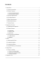
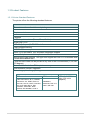
TTP-244 Pro Series THERMAL TRANSFER / DIRECT THERMAL BAR CODE PRINTER USER’S MANUAL Copyright Information © 2014 TSC Auto ID Technology Co., Ltd. The copyright in this manual, the software and firmware in the printer described therein are owned by TSC Auto ID Technology Co., Ltd., All rights reserved. CG Triumvirate is a trademark of Agfa Corporation. CG Triumvirate Bold Condensed font is under license from the Monotype Corporation. Windows is a registered trademark of Microsoft Corporation. All other trademarks are the property of their respective owners. Information in this document is subject to change without notice and does not represent a commitment on the part of TSC Auto ID Technology Co. No part of this manual may be reproduced or transmitted in any form or by any means, for any purpose other than the purchaser’s personal use, without the expressed written permission of TSC Auto ID Technology Co. Agency Compliance and Approvals EN 55022, Class A EN 55024 EN 60950-1 FCC part 15B, Class A AS/NZS CISPR 22, Class A EN 60950-1 GB 4943.1 GB 9254 GB 17625.1 Wichtige Sicherheits-Hinweise 1. Bitte lesen Sie diese Hinweis sorgfältig durch. 2. Heben Sie diese Anleitung fűr den späteren Gebrauch auf. 3. Vor jedem Reinigen ist das Gerät vom Stromentz zu trennen. Verwenden Sie keine Flüssig-oder Aerosolreiniger. Am besten eignet sich ein angefeuchtetes Tuch zur Reinigung. 4. Die Netzanschluß -Steckdose soll nahe dem Gerät angebracht und leicht zugänglich sein. 5. Das Gerät ist vor Feuchtigkeit zu schűtzen. 6. Bei der Aufstellung des Gerätes ist auf sicheren Stand zu achten. Ein Kippen oder Fallen könnte Beschädigungen hervorrufen. 7. Beachten Sie beim Anschluß ans Stromnetz die Anschluß werte. 8. Dieses Gerät kann bis zu einer Auß entemperatur von maximal 40℃ betrieben werden. CAUTION 1. HAZARDOUS MOVING PARTS IN CUTTER MODULE. KEEP FINGER AND OTHER BODY PARTS AWAY. 2. THE MAIN BOARD INCLUDES REAL TIME CLOCK FEATURE HAS LITHIUM BATTERY CR2032 INSTALLED. RISK OF EXPLOSION IF BATTERY IS REPLACED BY AN INCORRECT TYPE. 3. DISPOSE OF USED BATTERIES ACCORDING TO THE MANUFACTURER INSTRUCTIONS. “VORSICHT” Explosionsgefahr bei unsachgemäß en Austausch der Batterie. Ersatz nur durch denselben oder einem vom Hersteller empfohlenem ähnlichen Typ. Entsorgung gebrauchter Batterien nach Angaben des Herstellers. - ii - CE WARNING: This is a class A product. In a domestic environment this product may cause radio interference in which case the user may be required to take adequate measures. FCC WARNING: This device complies with Part 15 of the FCC Rules. Operation is subject to the following two conditions: (1) this device may not cause harmful interference, and (2) this device must accept any interference received, including interference that may cause undesired operation This equipment has been tested and found to comply with the limits for a Class A digital device, pursuant to Part 15 of the FCC Rules. These limits are designed to provide reasonable protection against harmful interference when the equipment is operated in a commercial environment. This equipment generates, uses, and can radiate radio frequency energy and, if not installed and used in accordance with the manufacturer’s instruction manual, may cause harmful interference with radio communications. Operation of this equipment in a residential area is likely to cause harmful interference, in which case you will be required to correct the interference at your own expense. IC WARNING (AVERTISSEMENT): This Class A digital apparatus complies with Canadian ICES-003. Cet appareil numérique de la classe A est conform à la norme NMB-003 du Canada. CCC 警告: 此为 A 级产品,在生活环境中,该产品可能会造成无线电干扰。在这种情况下,可能需要用户对干扰采 取切实可行的措施。 A 급기기 (업무용 정보통신기기) 이 기기는 업무용으로 전자파 적합등록을 한 기기이오니, 판매자 또는 사용자는 이 점을 주위하시기 바라며, 만약 잘못 판매 또는 구입하였을 때에는 가정용으로 교환하시기 바랍니다. - iii - Contents 1. Introduction............................................................................................................. 1 1.1 Product Introduction ......................................................................................... 1 1.2 Product Features .............................................................................................. 2 1.2.1 Printer Standard Features ................................................................................................ 2 1.2.2 Printer Optional Features ................................................................................................. 3 1.3 General Specifications...................................................................................... 4 1.4 Print Specifications ........................................................................................... 4 1.5 Ribbon Specifications ....................................................................................... 4 1.6 Media Specifications ........................................................................................ 6 1.7 Various Sensor ................................................................................................. 7 2. Operations Overview .............................................................................................. 9 2.1 Unpacking and Inspection ................................................................................ 9 2.2 Printer Overview ............................................................................................. 10 2.2.1 Front View ........................................................................................................................ 10 2.2.2 Interior View ..................................................................................................................... 11 2.2.3 Rear View ......................................................................................................................... 12 2.3 LED Indicators and Buttons ............................................................................ 13 2.3.1 LED Indication ................................................................................................................. 13 2.3.2 Buttons ............................................................................................................................. 13 3. Setup .................................................................................................................... 14 3.1 Setting up the Printer ...................................................................................... 14 3.2 Loading the Media .......................................................................................... 15 3.3 Loading the Ribbon ........................................................................................ 17 3.4 Install SD Memory Card (Option) ................................................................... 20 4. Using Printer......................................................................................................... 22 4.1 Power-on Utilities ........................................................................................... 22 4.1.1 Self Test and Dump Mode .............................................................................................. 22 4.1.2 Gap Sensor Calibration Utility ....................................................................................... 24 4.1.3 Printer Initialization ......................................................................................................... 25 5. Diagnostic Tool..................................................................................................... 27 - iv - 5.1 Start the Diagnostic Tool ................................................................................ 27 5.2 Printer Function .............................................................................................. 28 6. Troubleshooting.................................................................................................... 29 7. Maintenance ......................................................................................................... 30 Revise History .......................................................................................................... 31 -v- 1. Introduction 1.1 Product Introduction Thank you very much for purchasing TSC bar code printer. The TTP-244 Pro offers the largest media and ribbon capacities in its class. Unlike most printers, it can easily handle both a 300-meter ribbon and a full 8-inch OD roll of labels. With its fast 5 inch per second print speed, along with the largest memory capacity in its class, the TTP-244 Pro easily outperforms the competition. With its small, compact footprint and dual-motor design, the TTP-244 Pro is perfect for a wide variety of label and tag printing applications – everything from shipping labels to compliance and general purpose product-identification labels & tags. The TTP-244 Pro supports PDF417, QRCode, Datamatrix …. two-dimensional barcodes used to print complex transportation formats – a feature that makes it ideal for automobile service shops, stock rooms, and walk-in shipping and mail centers. To print label formats, please refer to the instructions provided with your labeling software; if you need to write the custom programs, please refer to the TSPL/TSPL2 programming manual that can be found on the accessories CD-ROM or on TSC website at http://www.tscprinters.com. − Applications Shipping and receiving Compliance labeling Asset tracking Inventory control Document management Shelf labeling and product marking Specimen labeling and patient tracking 1.2 Product Features 1.2.1 Printer Standard Features The printer offers the following standard features. Product standard feature Thermal transfer or direct thermal printing Black mark reflective sensor Gap transmissive sensor Ribbon end sensor 2 buttons 3 LED for printer status (Power, Error, On-line) 32-bit RISC CPU USB 2.0 (full speed) & RS-232 interface 8 MB SDRAM memory 4 MB FLASH memory Eltron® EPL and Zebra® ZPL emulation languages support Internal 8 alpha-numeric bitmap fonts Internal Monotype Imaging® true type font engine with one CG Triumvirate Bold Condensed scalable font Fonts and bar codes can be printed in any one of the four directions (0, 90,180, 270 degree) Downloadable fonts from PC to printer memory Downloadable firmware upgrades Bar code, graphics/image printing Supported bar code Supported image 1D bar code 2D bar code Code 39, Code 93, Code 128UCC, Code 128 subset A, B, C, Codabar, Interleave 2 of 5, EAN-8, EAN-13, EAN-128, UPC-A, UPC-E, EAN and UPC 2 (5) digits add-on, MSI, PLESSEY, POSTNET, RSSStacked, GS1 DataBar, Code 11 DataMatrix, Maxicode, PDF-417, Aztec, QR code -2- BITMAP, BMP, PCX (Max. 256 colors graphics) Code page Codepage 437 (English - US) Codepage 737 (Greek) Codepage 850 (Latin-1) Codepage 852 (Latin-2) Codepage 855 (Cyrillic) Codepage 857 (Turkish) Codepage 860 (Portuguese) Codepage 861 (Icelandic) Codepage 862 (Hebrew) Codepage 863 (French Canadian) Codepage 864 (Arabic) Codepage 865 (Nordic) Codepage 866 (Russian) Codepage 869 (Greek 2) Codepage 950 (Traditional Chinese) Codepage 936 (Simplified Chinese) Codepage 932 (Japanese) Codepage 949 (Korean) Codepage 1250 (Latin-2) Codepage 1251 (Cyrillic) Codepage 1252 (Latin-1) Codepage 1253 (Greek) Codepage 1254 (Turkish) Codepage 1255 (Hebrew) Codepage 1256 (Arabic) Codepage 1257 (Baltic) Codepage 1258 (Vietnam) ISO-8859-1: Latin-1 (Western European) ISO-8859-2: Latin-2 (Central European) ISO-8859-3: Latin-3 (South European) ISO-8859-4: Latin-4 (North European) ISO-8859-5: Cyrillic ISO-8859-6: Arabic ISO-8859-7: Greek ISO-8859-8: Hebrew ISO-8859-9: Turkish ISO-8859-10: Nordic ISO-8859-15: Latin-9 UTF-8 1.2.2 Printer Optional Features The printer offers the following optional features. User option Product option feature Centronics parallel & RS-232 serial interfaces or Centronics parallel & USB serial interfaces Bluetooth module (serial interface) 802.11 b/g/n wireless module (serial interface) External roll mount, media OD. 214 mm (8.4”) on a 1” or 3” core -3- Factory option ○ ○ ○ ○ SD card reader for memory expansion up to 4G 3” core label spindle KP-200 Plus keyboard KU-007 Plus programmable smart keyboard ○ ○ ○ ○ 1.3 General Specifications General Specifications Physical dimensions Enclosure Weight Power Environmental condition Environmental concern 232 mm (W) x 156 mm (H) x 288 mm (D) ABS plastic 2.5 kg (5.51 lbs) External universal switching power supply Input: AC 100-240V, 2.5A, 50-60Hz Output: DC 24V, 2.5A, 60W Operation: 5 ~ 40°C, 25 ~ 85% non-condensing Storage: -40 ~ 60°C, 10~ 90% non-condensing Comply with RoHS, WEEE 1.4 Print Specifications Print Specifications Print head resolution (dots per inch/mm) Printing method Dot size (width x length) Max.print speed Max. print width Max. print length 203 dots/inch (8 dots/mm) Thermal transfer or direct thermal 0.125 x 0.125 mm (1 mm = 8 dots) 5 ips (127 mm/sec) 4.25” (108 mm) 90” (2286 mm) 1.5 Ribbon Specifications Ribbon Specifications Ribbon outside diameter Max. 67 mm OD -4- Ribbon length Ribbon core inside diameter Ribbon width 300 m Ribbon wound type Ink coated outside 1” core 40 mm ~ 110 mm (1.6” ~ 4.3”) Note: The maximum length of ribbon depends on its thickness and core outside diameter. The formula below defines the correlation between ribbon roll length and ribbon core diameter. L= (D 2 d 2 ) , where 4t L = Ribbon length D = Max. roll diameter d = Ribbon core outside diameter t = Ribbon thickness -5- 1.6 Media Specifications Media Specifications Label roll capacity Media core diameter Media wound type 110 mm (4.33”) OD 25.4 ~ 76.2 mm (1” ~ 3”) Continuous, die-cut, black mark, External fanfold, notched Outside wound Media width Media thickness Label length 25.4 ~ 112 mm (1.0” ~ 4.4”) 0.06 ~ 0.19 mm (2.36 ~ 7.48 mil) 10 ~ 2,286 mm (0.39” ~ 90”) Media type -6- 1.7 Various Sensor Gap Sensor The gap sensor detects a label gap to locate the top of form of the next label. The sensor is mounted 4 mm off the center line of the main mechanism. . In case of Label Black Mark Sensor The black mark sensor locates the position of label by emitting infrared rays onto the black mark at the back of the ticket. The sensor is mounted 5.75 mm off the center line of the mechanism. In case of Ticket The default sensor position is (1) as shown on the figure below. To change to the (2) position, the customer should notify the manufacturer in advance. There can be only one position for the sensor. -7- Ribbon End Sensor The sensor detects the end portion of the ribbon. The ribbon end must be transparent. -8- 2. Operations Overview 2.1 Unpacking and Inspection This printer has been specially packaged to withstand damage during shipping. Please carefully inspect the packaging and printer upon receiving the bar code printer. Please retain the packaging materials in case you need to reship the printer. Unpacking the printer, the following items are included in the carton. One printer unit One Windows labeling software/Windows driver CD disk One quick installation guide One external auto switching power supply One power cord One label spindle Two fixing tabs Two ribbon spindles One paper core for ribbon rewind spindle If any parts are missing, please contact the Customer Service Department of your purchased reseller or distributor. -9- 2.2 Printer Overview 2.2.1 Front View 1 2 5 3 1. 2. 3. 4. 5. 4 P o w e r PAUSE button L E PWR., ON-LINE and ERR. indicators D FEED button i n Cover release button d Label dispense opening i c a t o r - 10 - 2.2.2 Interior View 6 7 8 USB inter face 1 9 2 3 4 10 5 11 2. US B Printer cover inte (in open position) rfa PAUSE button ce 3. PWR., ON-LINE, ERR. indicators 4. FEED button 5. Ribbon supply spindle 6. Fixing tabs 7. Label supply roll spindle 8. Ribbon mechanism 9. Ribbon rewind spindle 1. 10. Printer carriage release lever 11. Media sensor 12. Adjustable label guide 13. Platen - 11 - 12 13 2.2.3 Rear View 1 3 2 4 5 US B inte rfa ce 6 1. Power on/off switch 2. Power supply DC jacket 3. RS-232C interface 4. Label insert opening (For use with external media) 5. USB interface 6. Centronics interface (Factory option) Note: The interface picture here is for reference only. Please refer to the product specification for the interfaces availability. - 12 - 2.3 LED Indicators and Buttons 2.3.1 LED Indication LEDs Indication PWR. (POWER) Indicator The green PWR. indicator illuminates when the POWER switch is turned on. ON-LINE Indicator The green ON-LINE indicator illuminates when the printer is ready to print. When PAUSE button is pressed, the ON-LINE indicator flashes. ERR. Indicator (Error/Paper Empty) The red ERR. indicator illuminates in the event of a printer error, such as memory error, syntax error, and so forth. For a full list of error messages, please refer to section 6, Troubleshooting Guides. 2.3.2 Buttons Function Buttons PAUSE Button The PAUSE button allows the user to stop a print job and then continue the printing with a second depression of the button. By pressing the PAUSE button: (1) the printer stops printing after the printing label, (2) the PAUSE LED flashes, and (3) the printer will hold all data in memory. This allows for troublefree replacement of label stock and thermal transfer ribbon. A second depression of the PAUSE button will restart the printer. Note: If the PAUSE button is held down for more than 3 seconds, the printer will be reset and all data of the previous printing job will be lost. FEED Button Press the FEED button to feed the label to the top of form of the next label. - 13 - 3. Setup 3.1 Setting up the Printer 1. Place the printer on a flat, secure surface. 2. Make sure the POWER switch is off. 3. Connect the printer to the computer mainframe with the RS-232C or USB cable. 4. Plug the power cord into the power jacket at the rear of the printer, and then plug the power cord into a properly grounded receptacle. Note: Please switch OFF printer power switch prior to plug in the power cord to printer power jack. - 14 - 3.2 Loading the Media 1. Open the printer cover. 2. Disengage the printer carriage by pulling the printer carriage release lever on the left side of the platen. 3. Slide the label supply roll spindle through the core of a label roll and attach the fixing tabs onto the spindle. 4. Place the label roll into the label roll mount/ or external label roll mount. Feed the label under the carriage and over the platen. External Label Roll Mount (Option) - 15 - 5. Adjust the label guide to fit the width of the media. 6. Engage the printer carriage. 7. Wind the label roll until it becomes adequately taut. 8. Close the printer cover and press the FEED button three or four times until the green ON-LINE indicator illuminates. 9. When the printer is out of ribbon or media, the ON-LINE LED will not illuminate and the ERR. LED will flash. Reload the ribbon or media without turning off the printer power. Press the FEED button three or four times until the ON-LINE LED illuminates. The printing job will be resumed without data loss. Note: Please refer to videos on TSC YouTube or software/driver CD disk. . - 16 - 3.3 Loading the Ribbon 1. Place an empty paper core on the ribbon rewind spindle. 2. Insert the left side first. Mount the ribbon rewind paper core on the front hubs. 3. Please be noted that the bigger hub 1 side with 4 ribs must be installed toward the right side of ribbon mechanism. 2 4. Install a ribbon on the ribbon supply spindle. Mount the ribbon supply spindle on the rear hubs. - 17 - 5. Please be noted that the bigger hub side with 4 ribs must be installed toward the right side of ribbon mechanism. 6. Disengage the printer carriage by pulling the carriage release lever upwards. 7. Following the direction of the RIBBON label, pull the transparent ribbon leader to the front from under the ribbon mechanism. 8. Attach the ribbon leader to the empty paper core on the ribbon rewind spindle (with a tape). - 18 - 9. Rotate the ribbon rewind spindle until the ribbon overlaps the ribbon leader and stretches tight. 10. Engage the printer carriage. 11. Close the printer cover and press the FEED button until the green ON-LINE LED illuminates. Note: 1. Please install ribbon and media and close print head mechanism prior to turn on power. Printer will determine direct thermal or thermal transfer mode automatically while turning on printer power. 2. Please refer to videos on TSC YouTube or software/driver CD disk. - 19 - 3.4 Install SD Memory Card (Option) 1. Open the memory card cover. 2. Plus the SD memory card module on the main board. 3. Install the SD memory card. 4. Close the memory card cover. - 20 - * Recommended SD card specification. SD card spec SD card capacity Approved SD card manufacturer V1.0, V1.1 128 MB SanDisk, Transcend V1.0, V1.1 256 MB SanDisk, Transcend, Panasonic V1.0, V1.1 512 MB SanDisk, Transcend, Panasonic V1.0, V1.1 1 GB SanDisk, Transcend, Panasonic V2.0 SDHC CLASS 4 4 GB V2.0 SDHC CLASS 6 4 GB SanDisk, Transcend, Panasonic V1.0, V1.1 microSD 128 MB Transcend, Panasonic V1.0, V1.1 microSD 256 MB Transcend, Panasonic V1.0, V1.1 microSD 512 MB Panasonic V1.0, V1.1 microSD 1 GB Transcend, Panasonic V2.0 SDHC CLASS 4 microSD 4 GB Panasonic V2.0 SDHC CLASS 6 microSD 4 GB Transcend V1.0, V1.1 miniSD 128 MB Transcend, Panasonic V1.0, V1.1 miniSD 256 MB Transcend, Panasonic V1.0, V1.1 miniSD 512 MB Transcend, Panasonic V1.0, V1.1 miniSD 1 GB Transcend, Panasonic V2.0 SDHC CLASS 4 miniSD 4 GB Transcend V2.0 SDHC CLASS 6 miniSD 4 GB - The DOS FAT file system is supported for the SD card. - Folders/files stored in the SD card should be in the 8.3 filename format - The miniSD/microSD card to SD card slot adapter is required. - 21 - 4. Using Printer 4.1 Power-on Utilities There are three power-on utilities to set up and test hardware. These utilities are activated by pressing the FEED or PAUSE button and turning on the printer power simultaneously. The utilities are listed as below: 1. Self-test 2. Gap sensor calibration 3. Printer initialization Note: Please refer to videos on TSC YouTube or software/driver CD disk. 4.1.1 Self Test and Dump Mode Install the label first. Press the FEED button and then turn on the printer power. Do not release the FEED button until the printer feeds labels. The printer performs the following items: 1. Calibrate label pitch 2. Print out thermal print head check pattern 3. Print the internal settings 4. Enter dump mode To initiate the self test mode, the printer will calibrate the label length. If the label gap is not detected within 7", the printer stops feeding labels and the media is treated as continuous paper. In self test, a check pattern is used to check the performance of the thermal print head. Following the check pattern, the printer prints internal settings as listed below. When the self test is completed, the printer enters the dump mode. Please turn the printer's power off and then on to resume normal printing. - 22 - Self-test printout Model name F/W version Firmware checksum Printer S/N TSC configuration file System date System time Printed mileage (meter) Cutting counter Print speed (inch/sec) Print darkness Label size (inch) Gap distance (inch) Gap/black mark sensor intension Code page Country code ® Note: ZPL is emulating for Zebra language. ZPL setting information Print darkness Print speed (inch/sec) Label size Control prefix Format prefix Delimiter prefix Printer power up motion Printer head close motion RS232 serial port configuration Numbers of download files Total & available memory space Print head check pattern - 23 - Dump Mode After the self test, the printer enters the dump mode. In this mode, any characters sent from the host computer will be printed in two columns, as shown. The characters received will be shown in the first column, and their corresponding hexadecimal values, in the second. This is often helpful to users for the verification of programming commands or debugging of printer programs. Reset the printer by turning the POWER switch off and on. Hex decimal data related to left column of ASCII data ASCII Data 4.1.2 Gap Sensor Calibration Utility This utility is used to calibrate the sensitivity of gap sensor. Users may have to calibrate the gap sensor for two reasons: 1. The media is being changed to a new type. 2. Initialize the printer. Note: The ERR. LED may flash if gap sensor is not calibrated properly. Please follow the steps below to calibrate gap sensor: 1. Turn off the printer power and install blank labels (without any logo or character) on printer. - 24 - 2. Hold down the PAUSE button then turn on printer power. Release PAUSE button when the printer feeds labels. Do not turn off printer power until the printer stops and two green LEDs light on. Note: Black mark sensor has fixed sensitivity. It is no need to calibrate the black mark sensor 4.1.3 Printer Initialization Printer initialization sets printer parameters to default values. And it will not clear downloaded files resident in flash memory. Please follow the steps below to initialize the printer: 1. Turn off the printer power. 2. Hold down the PAUSE and FEED buttons and turn on the printer power. 3. Do not release the buttons until the three LEDs flash in turn. Note: 1. Printing method (thermal transfer or thermal direct printing) will be set automatically at the activation of printer power. 2. When printer initialization is done, sensor sensitivity is reset to default. Sensor calibration is required before printing labels. 3. Download files will not be deleted after printer initialization. For more information about deleting files, please refer to TSPL2 programming manual KILL command section or using DiagTool. Printer configuration will be restored to defaults as below after initialization. Parameter Speed Density Media Width Media Height Sensor Type Gap Setting Print Direction Reference Point Offset Post-Print Action Default setting 76.2 mm/sec (3 ips) 8 4” (101.6 mm) 4” (101.6 mm) Gap sensor 0.12” (3.0 mm) 0 0,0 (upper left corner) 0 Tear mode - 25 - Serial Port Settings Code Page Country Code Clear Flash Memory 9600 bps, none parity, 8 data bits, 1 stop bit 850 001 No - 26 - 5. Diagnostic Tool TSC’s Diagnostic Utility is an integrated tool incorporating features that enable you to explore a printer’s settings/status; change a printer’s settings; download graphics, fonts and firmware; create a printer bitmap font; and send additional commands to a printer. With the aid of this powerful tool, you can review printer status and setting in an instant, which makes it much easier to troubleshoot problems and other issues. 5.1 Start the Diagnostic Tool 1. Double click on the Diagnostic tool icon to start the software. 2. There are four features (Printer Configuration, File Manager, Bitmap Font Manager, Command Tool) included in the Diagnostic utility. Features tab Interface Printer functions Printer setup Printer Status - 27 - 5.2 Printer Function 1. Connect the printer and computer with a cable. 2. Select the PC interface connected with bar code printer. USB cable RS-232 cable 2 1 The default interface setting is USB interface. If USB interface is connected with printer, no other settings need to be changed in the interface field. 3. Click the “Printer Function” button to setup. 4. The detail functions in the Printer Function Group are listed as below. Function Reset Printer Description Calibrate the sensor specified in the Printer Setup group media sensor field Setup the IP address, subnet mask, gateway for the on board Ethernet Synchronize printer Real Time Clock with PC Initialize the printer and restore the settings to factory default. Reboot printer Print Test Page Print a test page Configuration Page Print printer configuration Dump Text To activate the printer dump mode. Ignore AUTO.BAS Ignore the downloaded AUTO.BAS program Exit Line Mode Exit line mode. Password Setup Set the password to protect the settings Calibrate Sensor Ethernet Setup RTC Setup Factory Default For more information about Diagnostic Tool, please refer to the diagnostic utility quick start guide in the software/driver CD disk \ Utilities directory. - 28 - 6. Troubleshooting The following guide lists the most common problems that may be encountered when operating this bar code printer. If the printer still does not function after all suggested solutions have been invoked, please contact the Customer Service Department of your purchased reseller or distributor for assistance. Problem Ribbon does not advance or rewind Poor print quality Power indicator on printer does not illuminate ON-LINE indicator is off, ERR. indicator is on Solution 1. The media and ribbon must be installed then engage the print head mechanism prior to turning on printer power. 2. Install the black ribbon spindle at the correct direction. 3. Please check the "Media settings method" in the driver if it is set to direct thermal mode. 1. Clean the thermal print head. 2. Adjust the print density setting. 3. Ribbon and media are not compatible. 4. Media thickness is over spec. 5. Check if correct power supply is connected with printer. 1. Check the power cord see whether it is properly connected. 2. Check if the LED on the power supply is illuminated. If it is not lit on, then the power supply is damaged. 3. Check if correct power supply is connected with printer. 1. Out of paper or out of ribbon If there is one beep sound when printer is error, then it's gap sensor problem. Please check the following items. Calibrate gap sensor or setup the paper length in labeling software/program properly. Install the paper at the correct If there are two beeps sound when printer is error then it's ribbon sensor problem. Please check the following items. Is outside wound ribbon is used with this printer? Is ribbon threaded correctly in the mechanism? Is paper core installed on the ribbon take up spindle? Continuous feeding when printing labels 2. Calibrate the sensitivity of gap sensor. 1. Check the driver or command script setting if sensor type is set properly. 2. Calibrate the gap sensor again if die cut media is used for printing. - 29 - 7. Maintenance This session presents the clean tools and methods to maintain your printer. 1. Please use one of following material to clean the printer. Cotton swab Lint-free cloth Vacuum / Blower brush 100% Ethanol or Isopropyl Alcohol 2. The cleaning process is described as following, Printer Part Method Interval 1. Always turn off the printer before cleaning the print head. 2. Allow the print head to cool for a Clean the print head when changing minimum of one minute. a new label roll. 3. Use a cotton swab and 100% Ethanol or Isopropyl Alcohol to clean the print head surface. Print Head Platen Roller Sensor Exterior Interior 1. Turn the power off. 2. Rotate the platen roller and wipe it thoroughly with water. Clean the platen roller when changing a new label roll Compressed air or vacuum Wipe it with water-dampened cloth Brush or vacuum Monthly As needed As needed Note: Do not touch printer head by hand. If you touch it careless, please use ethanol to clean it. Please use 100% Ethenol or Isopropyl Alcohol. DO NOT use medical alcohol, which may damage the printer head. Regularly clean the print head and supply sensors once change a new media to keep printer performance and extend printer life. - 30 - Revise History Date Content Editor 2015/3/12 Modify section 1 & 2 Camille 2015/7/8 Modify section 1.6 (media thickness) Camille - 31 - TSC Auto ID Technology Co., Ltd. Corporate Headquarters 9F., No.95, Minquan Rd., Xindian Dist., New Taipei City 23141, Taiwan (R.O.C.) TEL: +886-2-2218-6789 FAX: +886-2-2218-5678 Web site: www.tscprinters.com E-mail: [email protected] [email protected] Li Ze Plant No.35, Sec. 2, Ligong 1st Rd., Wujie Township, Yilan County 26841, Taiwan (R.O.C.) TEL: +886-3-990-6677 FAX: +886-3-990-5577