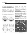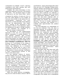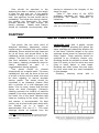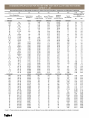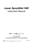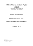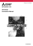
1
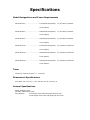
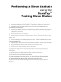
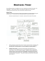
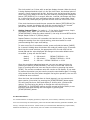
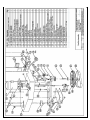
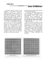
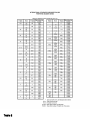
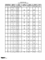
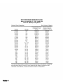
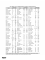
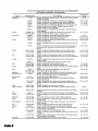
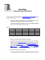
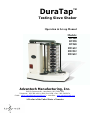
DuraTap
TM
Testing Sieve Shaker
Operation & Set-up Manual
Models:
DT168
DT258
DT268
DT1612
DT2512
DT2612
Advantech Manufacturing, Inc.
2450 S Commerce Dr., New Berlin, WI 53151 USA
Telephone: 262-786-1600 • (800) 511-2096 • Fax: 262-786-5074
E Mail: mailto:[email protected] • Web Site: www.advantechmfg.com
A Product of the United States of America
Introduction
Thank you for selecting this high-quality piece of testing equipment. We appreciate
your support and pledge to assist you in the service of your Advantech testing
apparatus.
The Advantech DuraTap™ is a low maintenance, heavy duty sieve shaker that will
provide consistent, reliable performance.
Gone are the days of needing to buy
“accessory packs” of repair parts for expected breakdowns like other sieve shakers
require.
The DuraTap™ does not use typical plastic and wear-surface parts.
This
industrial-strength unit is engineered with rugged steel and alloy materials ready to
withstand the everyday, harsh duty cycles. Grease fittings are provided to ensure
longer life for your bearings.
Each unit is “burned-in” guaranteeing performance
right out of the box.
This unit is ideal for use with aggregates, sands, cements, chemicals, powder metals,
cosmetics, pharmaceuticals and many other dry components in pellet, ground,
granular or powder form.
This unit is not recommended for wet sieving
operation.
Besides the physical nuts and bolts, this device is backed by a company with decades
of experience in the dedicated service of users in the powder and particulate
industries. We look forward to servicing you as well.
“The Leader in Sieving Technology ”
®
Specifications
Model Designations and Power Requirements
•Model DT168 ............................... 110VAC/60Hz operation,
8” (203.2mm) diameter
sieve capacity
•Model DT268 ............................... 220VAC/60Hz operation,
8” (203.2mm) diameter
sieve capacity
•Model DT258 ............................... 220VAC/50Hz operation,
8” (203.2mm) diameter
sieve capacity
•Model DT1612 ............................. 110VAC/60Hz operation, 12” (304.8mm) diameter
sieve capacity
•Model DT2612 ............................. 220VAC/60Hz operation, 12” (304.8mm) diameter
sieve capacity
•Model DT2512 ............................. 220VAC/50Hz operation, 12” (304.8mm) diameter
sieve capacity
Timer
•24 hours, reported accuracy +/- 2 seconds
Dimensional Specifications
•Unit base: 28” (71.1cm) L x 21” (53.cm) W x 25” (63.5cm) H
General Specifications
•Steel weldment base
•Durable, baked epoxy finish
•Unit capacity:
7 full height sieves with full height pan and cover
15 half height sieves with half height pan and cover
Installation & Set-up
Instructions
The DuraTap™ Testing Sieve Shaker is designed to give years of trouble-free service. To
assure that the device delivers optimum performance, several points must be observed before
putting the device into service.
1) Mounting
For best results, the unit must be permanently mounted. It is recommended that unit be
bolted to a steel table, heavily constructed wooden
bench or other suitable structure that will be able
to withstand the vibratory and hammering action
of the unit. The diagram below shows the location
of bolt holes provided for the mounting.
Use 3/8” diameter bolts (purchased locally) to
secure the unit. Inspect the mounting periodically
for loosening due to vibration.
2) Cleaning
The unit is painted with a baked epoxy finish that
will clean readily with a soft damp cloth. For best
results, vacuum any loose particulate materials
prior to wiping the machine clean.
3) Sieve Stack Height Adjustment
To assure repeatable and reproducible results in
testing, the drop of the hammer arm has been precalibrated during assembly. It is essential, however, that the stack of sieves be installed at
the proper height to obtain optimal results. To adjust the sieve stack height, please observe
the following:
•Be sure the hammer lift rod is at the lowest point of travel
•Load the stack of sieves, pan, cover and sieve cover with cork on to the sieve support plate
•Loosen the two wing screws on the sieve support plate
•Raise the sieve support plate along with the sieve stack until the hammer arm comes to an
approximately level position (see diagram)
•Tighten the wing screws and begin testing
H amme r liSieve
ft r od
Siev e co
v er wCork
ith c or k
Hammer Lift Rod
Cover
with
Siev e su p po rt pla te w ith w in g sc re w s
-9 0 °
4) Lubrication Instructions
This unit requires periodic lubrication at two different points in the mechanism. After
every 5 hours of operation, apply any general-purpose grease containing graphite to
the grease fitting at the rear of the top yoke. At the same time, apply grease to the
bulkhead grease fitting located on the left side of the machine base. Wipe off excess
grease before operating. Do not over apply grease.
Performing a Sieve Analysis
using the
DuraTapTM
Testing Sieve Shaker
1) Complete installation of the DuraTap™ Testing Sieve Shaker per instructions.
2) Plug device into the proper power source (be sure that voltage and cycle
requirements are observed).
3) Prepare the material sample to be tested using industry-specified sampling and
preparation procedures.
4) Select the sieves for the analysis.
5) Assemble the sieve stack, (coarsest sieve at the top, finest at the bottom) with
bottom pan.
6) Pour the sample to be tested onto the top sieve. Install a standard sieve cover
to prevent sample loss.
7) Place the spun sieve cover with cork from the DuraTap™ on top of the assembly.
8) Swing the hammer arm up past vertical until it comes to rest.
9) Slide the sieve stack assembly into the DuraTap™.
10) Adjust the height of the sieve stack assembly and sieve support plate per
instructions.
11) Bring hammer arm back down into place over the sieve cover.
12) Set the timer for the desired test interval.
13) Upon completion of the test interval, the unit will switch off automatically.
14) Swing the hammer arm up past vertical until it comes to rest.
15) Remove the sieve stack assembly, and proceed to weigh-up the retained
fractions.
Electronic Timer
In an effort to make our products even more responsive to needs of the users, the
DuraTap™ Testing Sieve Shaker now features a digital timer, with greater
reliability and precision than most conventional mechanical timers.
Digital Timer
The timer controls the cycle time of the sieving operation, as well as functioning as a
24-hour clock. The timer and clock setting procedure are described below.
Minimum operating time is 2 seconds, maximum 99 minutes 59 seconds.
1.
After applying an appropriate AC to the power input terminals, the display will
be blank and the beeper will beep for ¼ second giving the user notification
that the timer is now activated. The units’ default is in Minute [Mode].
2.
Setting Time of Day - Push and hold the button [SET/DISPLAY] for 1
second, the unit will default the time to 12:00am and enter the ‘Clock Set’
mode. While in this mode, buttons [MODE], [STOP] & [START/RESUME] are
disabled and the clock set LED will be turned ON. The user now can set the
time by pressing and holding either [INCREASE] or [DECREASE] button until
the desired time is achieved. If you do not wish to set the time of day, skip
step number 3.
The clock mode is a 12-hour with an am/pm display element. When the clock
is being displayed and the clock is in the pm time frame, the decimal point of
number 1-seven segment will be ON. Once the user has achieved the proper
clock value, they need to exit the clock set mode by pressing and holding the
button [SET/DISPLAY] for 1 second. After the 1 second, the beeper will beep
for 1 second giving the user notification that the mode is now exited. Once
the clock is set, the display will go blank and the clock set LED will turn OFF.
If the clock has been set and the user presses the button [SET/DISPLAY] for
less than 1 second, the display will show the current time for a 5 second
period and revert back to what was previously on the display.
3.
Setting Interval Timer - In modes 1 – 3, the device functions as a simple
countdown timer. When you set the value, press the button
[START/RESUME]. When the value reaches 0, the relay is turned OFF and the
beeper beeps 6 sets of 2 (250ms) beeps.
Repeat Feature- the timer will remember the last time set. If you desire to
change the setting from the original setting, press start switch to recall
previous setting then input new setting.
To enter one of the 3 countdown modes, press and hold the button [MODE]
for 1 second. Holding down this button the mode will switch every 2 seconds.
Each time the mode switches, the appropriate LED of mode LEDs will be
turned ON and the value displayed will change to the modes default value.
An audible ¼ beep will also be heard.
Mode 1
Mode 2
Mode 3
0 – 99 second:
DEFAULT DISPLAY = 01
0 – 99 minute:
DEFAULT DISPLAY = 00.00
0 – 99 hour: DEFAULT DISPLAY = 00.00
Once the countdown value has been set, you can now start the timer by
pressing the button [START/RESUME]. The relay is turned ON. While the
timer is counting down the user can stop the event by pressing the button
[STOP]. The current countdown value will remain on the display. If you want
to resume the session you just need to press the start button again. Counting
will proceed from the point where stopped. During this operation, the run LED
is blinked at once a second.
Once the timer has counted down to 0 and stopped, you can execute the
same session (time value) by pressing the [START/RESUME] button again.
This will recall the timer value and display it. At this point, you have two
options. The first being the ability to change the value by using the
[INCREASE] or [DECREASE] buttons and the second being the ability to use
the same value and starting the event again by pressing the
[START/RESUME] button.
For More Information…
For recommendations on sampling procedures, sample size, sieve selection, calibration, test intervals,
sieve care and cleaning and related topics, please see Advantech Manufacturing publication R1986AS, Test
Sieving: Principles and Procedures. Please contact your local Advantech Manufacturing representative,
Advantech Manufacturing, or order directly from our website www.advantechmfg.com.
www.advantechmfg.com
Test Sieving: Principles and
Procedures
A Discussion of the Uses, Capabilities, and
Limitations of Testing Sieves as Analytical Tools
Advantech Manufacturing, Inc.
THE LEADER IN SIEVING TECHNOLOGY®
2450 S Commerce Drive
New Berlin, Wisconsin 53151
262-786-1600
(800) 511-2096
FAX 262-786-5074
[email protected]
Foreword
Through ASTM and many industry organizations, standards have been
established for particle size for powder, granular and larger sized
materials. This manual has been prepared to help guide users of test
sieves through the proper procedures as well as provide many
additional tips that can enhance the existing procedures.
Our aim is to provide assistance to both the experienced and nonexperienced particle technologist in developing comprehensive particle
size test results, reduce test variations and enable the user to isolate
and identify sources of error or variations in the data.
Advantech Test Sieves, manufactured in the U.S.A., are the most
accurate test sieves available in the world today. The use of Advantech
Test Sieves will provide more precise and reproducible data, resulting
in better product control and a possible reduction of variables.
In preparing this manual, we have drawn from sources in the ASTM
publications, ISO Standards and various papers written by some of the
most renowned figures in the particle technology world. Additionally,
Advantech
personnel
have
contributed
sieving
technology
developments after having logged numerous years of "hands-on"
experience with many experts in the field. The result is a melding of
standards, research and opinion to provide a solid foundation for your
own particle size analysis program.
If additional help is desired in establishing your sieve analysis
procedure, or if you desire a list of suppliers of the equipment
highlighted
in
this
manual,
please
contact
Advantech
Manufacturing, Inc. 2450 S Commerce Dr., New Berlin, WI
53151
Telephone (800) 511-2096 or email: [email protected]
Copyright© 2001, Advantech Mfg.
Table of Contents
CHAPTER 1 -
. . . . . . . . . . . . . . . . . . WHAT IS SIEVING?
CHAPTER 2 -
. . . USES, LIMITATIONS AND ADVANTAGES
CHAPTER 3 -
. . WORKING GLOSSARY OF SIEVING TERMS
CHAPTER 4 -
. . . . . . . . . . . . . . SIEVE SPECIFICATIONS
CHAPTER 5 -
. . . . . . . SIEVE CALIBRATION PROCEDURES
CHAPTER 6 -
CHAPTER 7 -
. . . . . . PERFORMING THE SIEVE ANALYSIS
. . . . . . . . . . . SIEVE CARE AND CLEANING
CHAPTER 1
WHAT IS SIEVING?
A simplistic definition of sieving is the
separation of fine material from coarse
material by means of a meshed or
perforated vessel. Professor Terence Allen
characterizes sieving as "The aperture of a
sieve may be regarded as a series of
gauges which reject or pass particles as
they are presented to the aperture." (1) This
theory was actually in practice during the
early Egyptian era as grains were sized
with 'sieves' of woven reeds and grasses.
The level of sophistication increased
with the rise of the industrial revolution
and the need for more sophisticated
methods for classifying material by their
particle size. As requirements for sized
material rose, technology in producing
uniform sieving media increased. Woven
wire cloth was introduced as an alternative,
providing greater accuracy and durability.
At present, this woven cloth is available in
a range of sizes from 125 mm (5")
openings to 20 micrometer openings.
All mesh sizes are covered by both national
and international standards.
The need for particle size analysis in the
finer size ranges (i.e. 38 micrometers and
less) prompted the development of the
electrodeposited sieve. These sieves,
sometimes
called
electroformed
or
micromesh, are currently being produced
with openings as fine as 3 micrometers.
The mesh openings are extremely uniform
in both size and shape and maintain
exacting tolerances.
While the technology related to sieve
analysis has come a long way since the
reed sieves of ancient Egypt, few new
developments have come along since the
1940's. Professor Kurt Leschonski wrote
"Sieve analysis is one of the few methods
of particle size analysis which has escaped
modernization." (2)While the modernization
has not come in the actual hardware of
sieving, refinements in the application and
utilization of existing equipment has
proceeded.
CHAPTER 2
USES, LIMITATIONS AND ADVANTAGES
Harold Heywood wrote "I often refer to
sieving as the 'Cinderella' of particle size
analysis methods; it does most of the hard
work and gets little consideration."(3)
There are numerous reasons for the
selection of high quality testing sieves as a
first choice in particle size analysis work.
Leschonski said "... because of its
simplicity
everyone
immediately
understands the purpose of a stack of
sieves
and
its
operation
-and
its
inexpensive- ness." (4) Standard sieve
analysis is probably the fastest and most
widely used quality control procedure in
any powder process control industry. Used
frequently as a mediating device between
the production and sales divisions of a
process corporation or between the sales
force and the customer, test sieve analysis
work enjoys the universal recognition of
being the best 'quick and dirty' test
procedure for rapid particle size distribution
data. The outcome of the analysis is easily
calculated and interpreted for comparison
between laboratories. Start-up cost to
institute a basic sieving quality control
program is minimal, and operators at most
levels of training are capable of performing
a successful sieve analysis. With these
factors in mind, it is easy to see why
testing sieves are as ubiquitous as they are
in industry. Materials from crushed ore
chunks of over 114.3 mm (4 ½”) in
diameter to slurred alumina and porcelain
powders of less than 20 micrometers are
all analyzed with test sieves on a regular
basis.
Whether hand or machine sieving, wet or
dry preparations, analysis or production
work, testing sieves have found a niche in
the quality control laboratory. Given this
overall acceptance of test sieves as a viable
analytical device and the widespread
presence of the sieve in laboratories of all
industries, any shortcomings of such an
analytical device would be magnified. For
all of the advantages available to the test
sieve user, limitations must be recognized
and accounted for in the presentation and
analysis data.
Test sieves are individuals. Being
fabricated of a woven mesh material,
variations in the weave are common. The
chances of locating two sieves with an
identical distribution of opening sizes are
extremely remote. Due to these variations,
the reproducibility of test results between
sieves can be adversely affected. The
stringent standards imposed by ASTM, ISO
or other regulating bodies have established
tolerance factors which allow for the
permissible variations in the weave while
striving to maintain a level of uniformity in
the performance of the 'test grade' sieve
cloth. (See Table 1)
With this variation of opening sizes
present, some smaller than the nominal
and some larger, the time interval of the
sieve
analysis
becomes
extremely
important. If, for example, a sieve has
several openings far above the nominal
opening size for the particular mesh size,
and the test is run for 30 minutes, the
probability of larger-than-nominal particles
finding those oversized openings is much
greater than if the test was run for only 15
minutes. Similarly, if the sample of powder
contains a large percentage of elongated or
needle like particles, a longer test interval
would provide a greater likelihood that the
elongated particles will orient themselves
‘on end’ and pass through the openings. If
the sieving cloth has a wide range of
opening sizes, the sieving of this type of
material has a compounded error.
Another
factor
which
must
be
considered is the reaction of the material to
ambient conditions.
The most accurate
test sieve available would be of minimal
use if the relative humidity in the test lab
was 99%. Extremely dry conditions can
cause fine powders to adhere to the sieve
components and each other with strong
electrostatic charges. Additional types of
sieving problems are discussed in the
glossary section.
To minimize error caused by wire cloth
variation, steps must be taken at every
stage of fabrication that will assure the
uniformity of the woven mesh as well as
the
compliance
with
the
applicable
standards. Both the weaver and the test
sieve manufacturer must maintain a
constant monitoring program measuring
the actual opening sizes of the wire cloth
as well as the uniformity of those openings.
The loss to the manufacturers in rejected
out of specification sieve cloth is a gain to
the end-user in uniformity and compliance.
CHAPTER 3
GLOSSARY OF SIEVING TERMINOLOGY
Sieving terminology is frequently used
and abused in writing specifications for
materials. Listed below are some of the
most frequently used terms and a general
discussion of their meaning:
Agglomerate:
natural
tendency
of
materials to clump or ball together. This
condition is very common in materials with
high moisture, fat or oil content or those
with
fibrous
or
extremely
irregular
topography.
Blinding: plugging of the screen openings
with particles either exactly the same size
as the sieve opening or by fine particles
which build up on the wire mesh and
eventually
close
off
the
openings.
Frequently referred to as pegging. (Photo
Page 4)
Cover: stamped or spun lid that tightly
covers the top of a sieve to prevent the
loss of the material sample during sifting or
mechanical agitation.
Electrostatic charges: accumulation of
electrical charges on the particles and sieve
components
causing
clinging,
agglomeration or blinding. This condition is
frequently seen in hydrocarbon-based
materials, plastics, reactive metals, paint
pigments and powders with a large fraction
finer than 20 micrometers.
Extended rim pan: a sieving pan with a
skirt designed to nest within a sieve stack,
allowing multiple tests to be performed
simultaneously. Frequently called a nesting
pan or spacer.
Flow additive: powdered substance added
to the sample to reduce agglomeration,
neutralize static charges and improve the
flow characteristics of the sample. Common
additives are fine silica, activated charcoal,
talc, and other commercially produced
natural or synthetic substances. Generally,
the additive is pre- screened to a known
average particle size, blended with the
sample (approximately 1% additive by
weight) and then screened with the
additives value removed from the reported
data.
Frame: a rigid sidewall used to form the
body of the testing sieve. Common depths
are 50.8 mm (2" full height) for 8” sieves
and 25.4 mm (1" half height). Special
application sieves of other depths are also
in use.
Mesh: screening medium with openings of
uniform size and shape made of woven,
punched or electrodeposited material.
Pan: stamped or spun receiver of materials
passing through the finest sieve.
Skirt: section of test sieve below the sieve
mesh that allows for mating or nesting of
the sieves in a test stack.
Support mesh: coarse sieve cloth
mounted under fine sieve cloth in a test
sieve to provide extra strength. This is
widely used in wet sieving operations to
protect the fragile fine sieve cloth.
Frequently called backing cloth or rolled
backing cloth.
Test Sieve: screening medium (mesh)
with openings of uniform size and shape
mounted on a rigid frame, usually for
laboratory testing or small scale production
applications. The frames can be made of
various materials, the most common of
which are brass and stainless steel in a
cylindrical configuration, having a diameter
of 3", 5", 6", 8", 10", 12" or larger.
Wet sieving: the separation of fines from
the coarse portion of a sample while
suspended
in
an
aqueous
solution
introduced to a testing sieve. The liquid
medium is used to negate static charges,
break down agglomerates and lubricate
near-size particles. After the fines have
been washed through the sieve, the
residue is oven-dried and re-weighed.
CHAPTER 4
SIEVE SPECIFICATIONS
-Domestic and International
The U.S. Standard Sieve Series is a
metric system based series first suggested
by the American Society for Testing and
Materials in 1913. The opening sizes in this
sieve series are in the ratio of the fourth
root of two. This numerical relationship was
first suggested by Professor P .R. Rittinger,
a German researcher, in 1867.
In the fourth root of two series, every
opening size is 1.189 times the opening
size of the next smaller sieve. This
relationship continues into sieve opening
area measurement. The U. S. Sieve Series
provides that the area of each sieve
opening size is 1 1/2 times the area of the
preceding sieve size.
By using every other sieve in this
number series, the relationship becomes
based on the square root of two (1.414),
with the area of the opening being twice
that of the preceding sieve size. Thus, by
skipping two sizes, you create an area ratio
of 3 to 1, or by skipping three sizes, you
create a ratio of 4 to 1.
When selecting sieves from this series,
any number of sieves can be used for an
analysis. Care must be taken in selecting
each sieve between two points, every other
sieve, every fourth sieve, etc., to keep
within the mathematical progression of the
series.
After World War II, the International
Standards Organization (ISO) was formed
in an attempt to establish world standards.
Though the U.S. Sieve Series had proven
to be effective and was in use throughout
the world, members of the ISO would not
accept the U.S. Sieve Series as a world
standard. The ISO chose to adopt the
Preferred Number Series based on the
roots of ten. The Preferred Number Series
was suggested by Charles Renard of France
in 1879. His system is based on the tenth,
twentieth and fortieth roots of ten
(designated R-10, R-20 and R-40). See
Table 2.
A compromise was reached between the
ISO and the proponents of the U.S. Sieve
Series when it was discovered that every
third value in the R-40/3 table is in a step
ratio of 1.1885, sufficiently close to the
fourth root of two (1.1892) used in the
U.S. Sieve Series. In 1970, slight
adjustments were made in the U.S. Sieve
Series to align the series perfectly with the
ISO specifications.
Copies of these tables of specifications
can be found in Table 3.
CHAPTER 5
SIEVE CALIBRATION PROCEDURES
Quantifying
and
accounting
for
variations in test sieve results have
become two of the most important topics in
particle technology today. Once again, the
ubiquitous nature of stacks of test sieves in
powder labs around the world has
contributed to the scope of the dilemma in
sieve standardization and calibration. Kaye
states
"The
inaccuracies
and
the
uncertainties of characterization by sieve
fractionation arise from the experimental
problems of determining the sieve residues
and from the non-ideal nature of the
sieving surfaces." Further, "The presence of
a range of aperture sizes in any real
sieving surface is a source of error in sieve
based characterization studies since the
theoretical or nominal size of the sieve is
taken to be the boundary limit for the sieve
residue." (5)
Not only is the test sieve user plagued
with variations in the weave of the cloth,
but also confronted with the effects of
particle shape on sieving results.
Nearly
50 years ago, A.M. Gaudin wrote, "Powders
with identical size distributions, densities
and chemical composition may behave
quite differently as a result of variations in
particle shape between samples. For
example, powders consisting solely of
spherical particles are likely to have good
flow properties, while powders containing
needlelike particles will not." Further, "In
addition, it is impossible to isolate the
concepts of particle size and shape, since
the method of size measurement will
influence the particle size which is
determined.” (6)
Numerous approaches have been tried
to compensate for the effects of variations
in wire cloth and particle shape.
The
methods
have
fallen
into
3 basic
categories: 1) inspection of the mesh to
determine opening size, 2) material testing
of the sieves to determine if sieves fall
within performance specifications, and 3) a
combination of methods 1 and 2, assuring
compliance with both opening size and
performance specifications.
Probably the most elementary of the
inspection methods is the use of the etched
glass slide. This procedure relies on what
is referred to as the ‘Moire Effec’, which
compares the number of wires per inch in
the wire cloth sample to the number of
lines per inch etched on the glass slide. By
microscopically
measuring
the
wire
diameters, a rough estimate of the opening
size can be approximated. One major
short- coming of this procedure is the
assumption that all wire diameters within
the sample are the same. A slight variation
in wire diameter can translate to a
significant change in opening size.
An alternative to this measurement
approach is the use of a high-powered
optical comparator or profile projector. In
this method, powerful light sources
illuminate the mesh from both above and
below and project the image onto a glass
screen. Calibrated micrometer stages move
the mesh sample in relation to a reference
point allowing measurements with an
accuracy of 1 micrometer to be made on
both the opening and wire diameter. The
results are displayed on a numerical
readout. The broad field of view of the
comparator allows for the scanning of a
large number of sieve openings, facilitating
a more comprehensive picture of the
nature of the sieve cloth.
In the material testing of sieves,
powder samples are run on subject sieves
and the residue calculated. These values
are then compared with other sieves in
selecting what are often referred to as
'matched' sieves. There are a number of
shortcomings in this procedure also. The
first and foremost problem encountered is
that of compliance. Conceivably, it is
possible to find hundreds of sieves that will
provide the same performance data when
tested with a reference material and still
not meet ASTM standards.
While the sieves perform comparably,
they do not meet the basic criteria of ASTM
specifications, which should disqualify them
from use as a U.S. Standard Testing sieve.
Another problem encountered with material
matching is the use of reference samples
that are different in shape, size or density
than the users' products. For example, a
manufacturer of spherical steel shot would
yield significantly different results on a
sieve that had been matched with an
angular ground silica material. In this case,
both shape and density are considerably
different. The key to proper matching is
using the end-users own product or a
material that approximates the product
most closely.
The final approach is a combination of
the first two methods. First, the sieve is
inspected optically for compliance with all
applicable standards. Openings and wire
diameters are measured, not averaged.
After the sieve opening distribution has
been characterized and evaluated, actual
material testing can begin. During the
material testing, samples of the user's
product are used for the standardization
procedure.
All
tests
are
run
for
repeatability and the variation between test
results calculated. This procedure yields a
testing sieve with known values in the two
most essential parameters compliance with
specifications and performance under
duplicate test conditions.
An alternative that has been used with
some success is the use of correction
factors between sieves. Once a 'master set'
of sieves has been established, a reference
sample is tested on the stack. The values
are calculated and retained. As new sieves
are acquired, the original reference sample
is tested on the new set and the values
calculated. Any variations between the
sieve stacks can be compensated for with
correction factors or multipliers. For
example, a sieve in stack 3 may retain
more or less than the comparable sieve in
the master set. A multiplier of magnitude
greater than or less than 1 is necessary to
calculate the comparable retention value
on that sieve when compared to the master
set. In this way, every sieve in use can be
compared to the master set to standardize
sieving results. Whatever method you use,
it is essential that your starting point is
based on ASTM specifications. This
CHAPTER 6
compliance
is
necessary
to
assure
uniformity between and within industries.
PERFORMING THE SIEVE ANALYSIS
In obtaining meaningful sieve analysis
data, six major steps are recommended. 1)
Obtain a representative sample of the
material to be evaluated. 2) Prepare the
sample for evaluation; this may involve
washing and/or drying the sample.
3)
Reduce the sample to a size suitable for
the sieve analysis procedure. 4) Perform
the actual sieve analysis procedure. 5)
Compute the data and convert the data
into a usable format. 6) Organize the data
and
assemble
the
information
for
presentation.
Granular and powder materials are
prone to segregation during movement and
storage of the products. This segregation
can be due to the disparity of the particle
sizes and the varied densities for blended
products.
When forming a stockpile of
material, the larger, coarser particles are
heavier and tend to roll to the lowest
portion and outer perimeter of the cone.
The finer particles are lighter and more
angular and remain concentrated at the top
and through the vertical center of the cone.
Obtaining samples from only the outer
perimeter or from the top of the cone
would not provide a sample which would be
representative of the entire batch.
Sample extraction and preparation is
the most commonly overlooked variable in
sieve standardization programs. Testing
bias can be added at many places along
the progression from the raw materials
received from a supplier, samples taken at
each stage of production, sample reduction
procedures and samples when the product
is ready for shipment to the customer. The
way the samples are extracted from the
original bulk volume varies with the way
the materials are received, produced or
stored. The ideal sampling method is one
which provides the most representative
sample with the least amount of material
required.
The following paragraphs were first
published in the ASTM technical publication
STP 447 A. The collaborative efforts of the
authors have produced a section on
sampling technique which will aid in
obtaining representative test samples from
larger test sources…(7)
Sampling from a chute or belt
Accuracy in sampling is obtained where
material is flowing from a chute or belt
conveyor. The ideal place to collect the
sample is where the material drops from
the chute or belt. If the material stream is
small enough, use a pail or other suitable
receptacle which can be swung completely
across the flowing stream in a brief interval
of time and with uniform movement. The
sampling receptacle should not be allowed
to overflow, because the overflow would
tend to reject a higher proportion of the
larger
particles
that
exist
in
a
representative
sample.
Mechanical
sampling devices are available for selecting
samples automatically from a stream at
uniform time intervals.
Sampling from carload shipments of
coarse bulk material
For coarse materials, such as crushed
stone and gravel, shipped in railroad cars,
a recommended method is to dig three or
more trenches at least 30.48 cm (1 foot )
deep and approximately 30.48 cm
(1
foot)) wide at the bottom. Equal portions
are taken at seven equally spaced points
along the bottom of the trench by pushing
a shovel downward into the material and
not by scraping horizontally. Samples from
trucks, barges, or boats should be taken in
the same manner as from railroad cars,
except that the number of trenches should
be
adjusted
to
the
size
of
the
transportation unit and tonnage involved.
Sampling from carload shipments of
fine bulk materials
One established method for sampling a
carload of bulk granular material is to take
eight equal samples, (approximately 700 to
1000 grams each) from the bottom of a
30.48 cm (1 foot)) conical excavation.
Samples should be suitably spaced to
represent the length and width of the car
and then combined into a single gross
sample.
Sampling bulk shipments of
material with a sampling tube
fine
An alternate and simpler method of
sampling a carload, or other bulk quantity
of fine or granular material is by use of a
sampling tube which, for this purpose,
should be 38.1 mm (1 1/2 inches ) by
approximately 1.829 m (6 feet ). Five or
six insertions of the tube will produce
approximately, a 2 pound (907g) sample.
manner that the composite will have the
same grading as the larger amount.
Reduction of gross sample to test size
for sieve analysis
After the gross sample has been
properly obtained, the next step is to
reduce it to a suitable size for sieve
analysis without impairing in any way the
particle size distribution characteristics of
the original sample. This phase of the
operation should follow the applicable
procedures described in the succeeding
sections and should be performed with as
much care as was used in the collection of
the gross sample and in performing the
sieve test.
Sampling from a carload of bagged
material
One method of sampling a carload of
material shipped in bags is to select, at
random, a number of bags equal to the
cube root of the total number of bags in
the car and to take suitable portions (800
to 1000 grams for minus 6 mm material)
from each of the selected bags for a
combined gross sample.
Sampling from a pile
In sampling from a pile, particularly
material like crushed stone or coal
containing large particles, it is extremely
difficult to secure samples that are truly
representative. At the apex of a conical
pile, the proportion of fines will be greater,
while at the base; the percentage of coarse
particles will be greater. Therefore, neither
location will be representative of the whole.
In a shoveling process, every fifth or tenth
shovel, etc., should be taken depending on
the amount of the sample desired. The
sample should consist of small quantities
taken at random from as many parts of the
pile as are accessible and taken in a
Coning and quartering
Pile the gross sample in a cone, place
each shovel full at the apex of the cone,
and allow it to run down equally in all
directions. This will mix the sample. Then
spread the sample in a circle and walk
around the pile, gradually widening the
circle with a shovel until the material is
spread to a uniform thickness.
Mark the flat pile into quarters, and
reject two opposite quarters. Mix again into
a conical pile, taking alternate shovel-fulls
from the two quarters saved. Continue the
process of piling, flattening, and rejecting
two quarters until the sample is reduced to
the required size.
Sample splitters and reducers
Gross samples, if not too large, may be
reduced to test sample size by one or more
passes through a sample splitter or Jones
type riffle, which will divide a sample in
half while maintaining the particle size
distribution of the original sample. By
repeated passes, the sample can be split
into quarters, eighths, and so on until the
size of the sample desired is obtained. For
larger gross samples, sample reducers are
available which will select a representative
1/16 part with a single pass. After just two
passes
through
such
a
unit,
a
representative one pound sample can be
obtained from an original 256 pounds.
Three passes will give a one pound sample
from two tons of material. Always make
sure that the passages in the splitter or
reducer are at least three times the size of
the largest particle in the sample. Do not
attempt to arrive at exactly the amount of
material specified for the test. If a 50
gram sample is desired, arrive as near to
this amount as practicable, because it will
make no difference in the test percentage
results whether the sample is slightly
larger or smaller. In attempting to arrive
at an exact weight, the tendency is to
discriminate by the removal of sizes that
are not representative of the whole, thus
destroying the representative quality of the
sample.
Size of Sample in the Test
There is a natural tendency, although
incorrect, to use an excessively large
sample in the test. In most cases, a
smaller sample will provide a more
accurate analysis. Beware, however, that
the more you split, the greater the chance
of error. Testing sieves are a go or no go
gauge; if the sample is too large it will not
permit each of the particles an opportunity
to present themselves to the screen
surface.
Often the limiting factor for
reducing the sample size is the accuracy of
the weighing device used to determine the
amount of material retained on the sieve.
Generally a 25 to 100 gram sample is
recommended. However, if it is necessary
to establish the correct sample size, utilize
the following procedure: Using a sample
splitter, reduce samples to weights (i.e. 25,
50, 100, 200 grams).
Analyze these
various sample sizes on a selected nest of
sieves for a period of five minutes
preferably using a mechanical sieve shaker.
If the test with the 100 gram sample shows
approximately
the
same
percentage
passing the finest sieve as the 50 gram
sample, whereas the 200 gram sample
shows a lower percentage, this would
indicate that the 200 gram sample is too
large and the 100 gram samples would be
satisfactory.
Then run the 100 gram
sample on the same set of sieves for the
same time period to see if repetitive results
are obtainable.
A useful table of recommended sample
sizes for tests with 200 mm or 8” diameter
sieves is presented in Table 4 1. Note that
the table gives sample sizes listed by
volume. Recommended sample weights in
grams can be determined by multiplying
the values in Column 3 and 4 by the bulk
density (grams per cubic centimeter) of the
material to be tested rounded out within a
reasonable tolerance. If the actual bulk
density of a certain material is not known,
they typical density factor for the most
nearly similar material listed in Table 5 2
may by used.
To perform the actual sieve analysis,
sieves should be chosen in a sequence as
described earlier. Use every sieve, every
other sieve, or every third sieve, etc.
between the desired size parameters. The
use of sieves in this sequential order will
allow for better data presentation and a
more meaningful analysis of the test
results.
Care should also be taken in
selecting the proper sieves to avoid
overloading any sieve with an especially
large material peak.
For example, a
specification may require 96% of the
sample be retained above a #50 mesh
sieve.
The proper way to perform an
analysis of this nature is to use ’relief
screen’, that is, sieves in the 30, 35, 40
and 45 mesh ranges to remove some of
the burden from the critical cut point of 50
mesh. If the relief sieves are not used, the
particles of exactly 50 mesh size or slightly
larger may become wedged in or forced
through the sieve openings by the mass of
material resting above them.
Large
concentrations of material on one sieve
reduce the opportunity for near sized
material to pass through the sieve resulting
in a larger portion of the material retained
on the test sieve. The sieve cut point
would be inaccurate and the sample would
not meet the specifications for the test.
The
selected
sieves
should
be
assembled with the coarsest sieve at the
top of the stack and the balance of the
stack in increasing magnitude of fineness
(increasing sieve numbers with smaller
openings).
The stack should include a
1
With the inclusion of the new ASTM E 11-09 Standards
Table, this is now featured in Table 5.
2
With the inclusion of the new ASTM E 11-09 Standards
Table, this is now featured in Table 6.
cover on the top sieve and a pan below the
finest sieve.
The sieve stack can be
shaken then rapped by hand or mounted in
a sieve shaker with a motorized or
electrostatic drive mechanism.
While many applications still use the handshaken method for sieving, motor driven
shakers have proven to be much more
consistent, minimizing variations related to
operator procedures. In powder analysis
below the 100 mesh range, the sieve
shaker should be equipped with a device to
impart a shock wave to the sieve stack at
regular intervals. This hammer or rapping
device is necessary to reorient the particles
on the sieve and impart some shear forces
to near-sized particles blocking the sieve
openings.
Recommended Time Intervals
The duration of the sieving interval is
usually regulated by industry standards, or
by
in-house
control
specifications.
Commonly, 10, 15 or 20 minute tests are
used as arbitrary sieving intervals.
To
determine the best interval for a new
material, or to double check the accuracy
of existing specifications, the following
procedure can be used. Select the desired
sieves for the analysis. 1) Weigh up a
sample of the material to be tested and
introduce it to the complete sieve stack. 2)
Shake the sieve stack for a period of 5
minutes. 3) Weigh the residue in the pan
and calculate the percentage in relation to
the starting weight. 4) Reassemble the
stack and shake for one additional minute.
5) Repeat the weigh-up procedure and
calculate
the
percentage.
If
the
percentage of fines increased more than
1% between 5 minutes and 6 minutes,
reassemble the stack and shake for an
additional minute. The data can be plotted
as percentage throughput versus time for
each data point you calculate. When the
change in the percentage of fines passing
in the 1 minute period drops below 1%, the
test can be considered complete. Record
the total testing time for subsequent
analyses.
Another type of sieve analysis is the wet
sieve test. In this method, the sample is
weighed and then washed through the
finest sieve in the stack with water, a
wetting agent (water based), or some
other compatible solvent. After thoroughly
washing the fines from the raw sample, the
residue is dried either over a hot plate or in
an oven. The temperature of the sieve
should be maintained below 149°C
(300°F) 3 to avoid loosening of the sieve
cloth or failure of the solder joint. After
drying, the residue is then sieved normally
on the balance of the sieve stack. The loss
in weight not accounted for on the coarse
screens is assumed to be fines or soluble
material.
Wet sieve analysis is especially helpful
when working with naturally agglomerated
materials, ultra-fine powders with severe
static changes and in samples where fine
particles tend to cling to the coarse
fractions in the blend. The disadvantages
associated with wet sieving are primarily
the time period required to perform the
analysis due to the additional washing and
drying time and the possible damage to the
sieve mesh by overloading. A common
practice with wet sieving operations is
brushing or forcing the sample through the
mesh while the liquid medium is directed
on the sieve. This pressure can distort the
sieve openings or tear the mesh at the
solder joint through stress. Therefore, this
procedure is not recommended. Once the
sieving interval is complete, whether dry or
wet sieving is used, the residue on each
sieve is removed by pouring the residue
into a suitable weighing vessel. To remove
material wedged in the sieve’s openings,
the sieve is inverted over a sheet of paper
or suitable collector and the underside of
the wire cloth brushed gently with a nylon
paint brush with bristles cut to a 25.4 mm
(1”) length. The side of the sieve frame
3
Advantech metal framed sieves should not exceed 261° F
(127° C). Solder will begin to soften at this point.
may be tapped gently with the handle of
the brush to dislodge the particles between
brush strokes. At no time should a needle
or other sharp object be used to remove
the particles lodged in the wire cloth.
Special care should be taken when
brushing sieves finer than 80 mesh.
Brushing can cause distortions and
irregularities in the sieve openings. The
procedure is repeated for each sieve in the
stack and contents of the pan.
The individual weights retained on the
sieves should be added and compared to
the starting sample weight. Wide variations
or sample losses should be determined
immediately. If the finished sample weight
varies more than 2% from the initial
weight, the analysis and sample should be
discarded and the test performed another
sample.
If the sample weights are
acceptable, complete the calculations and
report the individual weights retained on
each sieve.
Presentation and analysis of the
resulting data is frequently made easier by
plotting on one of a number of graph
formats. The most common graphic
presentation is the plotting of the
cumulative percentage of material retained
on a sieve (plotted on a logarithmic scale)
versus percentage (plotted on a linear
scale). The resulting curve allows a quick
approximation of the sieve size at the fiftypercentile point of accumulation. The curve
also shows the smoothness of the
distribution by revealing the presence of
bimodal blends in the sample. Other
plotting techniques include log-log and
direct plotting of micron size versus
percentage retained.
Care should be exercised in the
analyzing the data in relation to the length
of time the test was run. If the sample
contains a large amount of elongated or
near- size particles, the test results can be
misleading. The longer the sieving interval,
the greater the opportunity for these
problem particles to pass through the
sieve’s openings.
Ideally each fraction
should be inspected microscopically after
CHAPTER7
*Do NOT ultrasonically clean precision electroformed test
sieves. Refer to the Handling and Use Instructions on the
sieve jewel case.
4
With the inclusion of the new ASTM E 11-09 Standards
Table, this is now featured in Table 7.
SIEVE CARE AND CLEANING
Test sieves, like any other piece of
analytical laboratory equipment, require
regular care to maintain their performance
standards. Sieves should be kept clean and
dry at all times, and stored either in the
cardboard carton provided or in a suitable
cabinet. The wire cloth must be taut and
free from variations in opening size. For
this reason, cleaning procedures must be
clearly
delineated
as
part
of
a
comprehensive sieving program.
5
Test
sieves
should
be
cleaned
ultrasonically on a regular basis.* For some
installations, this may be done at the end
of a shift or at the end of a week, but must
be done regularly to assure accurate
sieving results. The sieves should be
immersed in an ultrasonic cleaner filled
with a solution of a mild detergent and
water. Prior to reuse, ensure that the test
sieves are dried thoroughly. Ultrasonic
cleaning prevents the buildup of particles
trapped in the sieve openings and prolongs
the useful life of the sieve. Between test
clean-up, brushing of the mesh, sizes 100
and coarser, is recommended. For best
results, use a nylon bristle paint brush with
the
bristles
cut
to
a
length
of
approximately 25.4 mm (1"). The sieve
openings should be brushed from the
5
sieving to determine the integrity of the
sieve cut point.
Table 6 4 lists many of the ASTM
published standards on sieve analysis
procedures for specific materials or
industries.
underside only with a gentle circular
motion. Vigorous brushing will distort the
sieve openings and reduce the effective life
of the sieve. Particles lodged in the sieve
openings should never be removed with a
sharp object. These particles should be
removed in an ultrasonic cleaner only.
Brushing should be avoided on sieves finer
than 100 mesh, as the fine wires are more
likely to bend, distort or even break.
Brushing can often loosen the wire cloth;
the finer mesh sizes are most susceptible
to this damage.
Similarly,
cleaning
sieves
with
a
compressed air jet is common, but this can
damage the sieve openings on the finer
mesh sieves. The concentrated jet of air
can cause severe 'local' damage to the wire
cloth, and significantly reduce the accuracy
of the sieve mesh.
With proper care, sieves will perform
accurately for many years. Typical wear
does not usually change the opening sizes,
but can abrade the 'knuckles' or crimps of
the wire. A sieve with noticeable sagging of
the cloth should be replaced. Fine mesh
sieves that are torn should not be resoldered, as the localized heat of the
soldering iron can distort the openings.
Epoxies have been used for repairs, but
tend to block a large percentage of the
openings reducing the opportunity for
particles to pass through the openings in
the allotted agitation time. Epoxies may
become too brittle for the flexing of the
wire cloth and can fracture with use.
Good general laboratory procedures
should be observed with testing sieves as
with any other piece of test equipment.
Testing should be performed with clean,
uncontaminated sieves, especially when
using a sieve for the first time. With proper
care and cleaning coupled with a good
calibration procedure, any test sieve should
provide many years of consistent service.
EPILOG
We hope that the characterization of testing sieves
and their uses presented in this manual will serve as an
enhancement to your current particle size analysis
BIBLIOGRAPHY
program. By maximizing the analytical advantage
potential of testing sieves while minimizing and
1. Allen,
Terence, Particle
Measurement, and inaccuracies, the
compensating
forSize
shortcomings
Chapman
Hall, New
York,
1981. and precise testing tool.
testingandsieve
can be
a viable
Care, maintenance and proper test procedures are as
2. Leschonski,
Kurt, a"Sieve
Analysis,
Particle
Size more
critical with
testing
sieveThe
asCinderella
they areofwith
other,
Analysis
Methods?",particle
Powder Technology,
Elsevier Sequoiz S.A.,
sophisticated
size analyzers.
Lausanne, 24 (1979).
Compliance with applicable industry, National and
3. Heywood,
Harold, Proc.
Particle Size Analysis
Conference,
International
specifications
is essential.
TheBradford,
intent of
1970.
these regulating bodies is the formulation of general
standards to assure uniformity in testing standards
observed
by Ibid.
both the buyer and producer. The accepted
4. Leschonski,
Kurt,
specification should be the foundation for the in-house
testing procedure.
5. Kaye, Brian, Direct Characterization of Fine Particles,
John Wiley
andaccuracy
Sons, New is
York,
1981.dependent on the technique
Testing
highly
of the operators. Interpretation of data should be
6. Gaudin,
A.M., overstated
Principles of Mineral
McGraw-Hill,
neither
nor Dressing,
understated
in terms of
importance.
The effects of variables must be
New
York, 1939.
understood, accepted and factored into final data
7. MNL32
“Guidelines
forthese
Establishing
Sieve Analysis Procedures”,
analysis
to avoid
shortcomings.
th
4 Edition, 1998.
NOTE: To aid in making this manual as understandable and
comprehensive as possible, minor changes in spelling and
grammar have been made to some of the quoted references.
These changes have not altered the statements made but
have aided in clarifying the thoughts of the authors.
BIBLIOGRAPHY
1. Allen, Terence, Particle Size Measurement, Chapman and Hall, New
York 1981.
2. Leschonski, Kurt “Sieve Analysis, The Cinderella of Particle Size
Analysis Methods?”, Powder Technology, Elsevier Sequoiz S.A.,
Lausanne, 24 (1979)
3. Heywood, Harold, Proc Particle Size Analysis Conference, Bradford,
1970.
4. Leschonski, Kurt, Ibid.
5. Kaye, Brian, Direct Characterization of Fine Particles, John Wiley
and Sons, New York, 1981.
6. Gaudin, A.M. Principles of Meneral Dressing, McGraw-Hill, New York
1939.
7. Manual on Test Sieving Methods-STP 447 A, American Society of
Testing and Materials, Philadelphia, 1969.
Table 1
Table 2
Table 3 . . .
Table 3, cont’d.
Table 4
Table 5
Table 6
DuraTap
Frequently Asked Questions
For specific sieving procedures, please refer to Test Sieving: Principles and Procedures located
in the User’s Manual. For added reference, a DuraTap Parts Diagram is located in the front
portion of the User’s Manual.
1.
What is the oscillation displacement on the DuraTap and how many
oscillations and taps per minute does the DuraTap produce?
The DuraTap’s oscillation displacement is 1-1/8” x ¾”. The oscillations and taps
per minute will be dictated by the model DuraTap you have. Please see the chart
below for approximate oscillations and taps per model.
Chart 1A
Model
Voltage
Hertz
DT158
110
50
DT168
110
60
DT258
220
50
DT268
220
60
DT1612
110
60
DT2612
220
60
DT2512
220
50
*These are approximate oscillations and taps per minute.
2.
*OPM
267
278
268
278
278
278
268
*TPM
150
154
154
152
154
152
154
What sort of maintenance is required for the DuraTap?
The DuraTap for the most part just needs to be kept clean. There are two grease
fittings on the DuraTap which require service after every five hours of operation.
(Please refer to the DuraTap Parts Diagram in the front portion of the User’s
Manual.) One port is on top of the unit in the BA106/BA119 Yoke (30/30a). This
fitting feeds the DA211 Eccentric (5) housed in the BA102/BA120 Yoke (30/30a).
The second port is on the lower rear part of the BA101 Tower & Base Assembly
(45). This fitting feeds the DA211 Eccentric (5) housed by the DA201 Lower
Carriage Plate (21). The BA105 Stationary Block (48) should also be periodically
greased. A Moly EP (extreme pressure) multi-purpose grease is recommended.
3.
Does the DuraTap have to be calibrated?
The DuraTap is not a calibrated machine. The taps and oscillations can be verified
to make sure the machine is still operating at manufacturer’s specification. (Please
refer to Chart 1A). The oscillations and taps per minute are basically a product of
motor rpm, line-in voltage and the hertz of that voltage.
Test sieves, however, can be certified using Advantech’s Centerline© Premium
Sieve Certification. Utilizing our sophisticated image analyzer traceable to NIST,
your sieve may be tested to any of the following:
4.
•
ASTM E 11 Inspection Certification: Sieves measured to this standard will
have a percentage of openings and 10 wire dimension measured. This
certificate provides a confidence level of 99% that the sieve is within the
specifications.
•
ASTM E 11 Calibration Certification: Sieves measured to this standard will
have at least twice as many apertures measured than inspection sieves,
thereby providing an increased confidence level of 99.73%
•
Please contact our Customer Service Team at 800.511.2097 or
[email protected] for instructions on how to send sieves in for service.
Does Advantech calibrate/certify test sieves for the DuraTap?
Yes. Test sieves can be certified using Advantech’s Centerline© Premium Sieve
Certification. Please see the answer to question three for specifics on the varied
levels of certification service Advantech offers. For a suggested re-certification
schedule, please contact our Customer Service Team at 800.511.2097 or
[email protected].
5.
How many sieves can I fit in my DuraTap?
Please refer to Chart 5A for details on the DuraTap’s sieve capacity. Fewer sieves
may be used by loosening the nuts and adjusting the height of the BA132/BA122
Sieve Support Clamp Assembly (36/36a) to the level necessary to securely hold
the sieve stack.
See Figure 6A for an example of a properly constructed and
inserted sieve stack.
DuraTap Sieve Capacity
Chart 5A
8” or 203.1 mm
12” or 304.8 mm
6.
Half Height
13
7
Intermediate Height
N/A
6
Full Height
6
3
Pan
1
1
My DuraTap is making a lot of noise and the sieve stack seems unstable in
the machine. What is wrong?
The sieve stack may have been improperly constructed and inserted.
Cover
1
1
•
•
•
Figure 6A
•
•
Figure 6B
7.
Start the sieve stack with the pan at the very bottom.
Load the sieves on top of the pan. An extended rim pan
may be inserted within the stack to run multiple samples.
See Figure 12A for an example of the extended rim pan.
Bear in mind the overall height of the sieve stack may not
exceed the capacities as shown in Chart 5A.
Introduce the sample and place the BA106/BA119 DuraTap
Sieve Cover (30/30a) on top of the sieve stack as shown in
Figure 6A. Figure 6B illustrates an improperly installed
DuraTap Sieve Cover.
Place the sieve stack onto the BA132/BA122 Sieve Support
Clamp Assembly (36/36a)
Adjust the BA132/BA122 Sieve Support Clamp Assembly
(36/36a) up far enough that the sieves will be securely
held in place as shown in Figure 6C. Be certain you have
the BA106/BA119 DuraTap Sieve Cover (30/30a) situated
so the dimple in the center can receive the cork or rubber
plug as shown is Figure 6A. If the cover is upside-down,
the sieves will not be properly held in place and the BA103
Hammer Arm (1) will fall on metal rather than the plug;
causing the “sloshing” of the sieves in the assembly and
the very noisy tapping.
Figure 6C
My DuraTap is making a slapping noise and the oscillation displacement
seem to be off. What is happening?
The BA105 Stationary Block (48) is manufactured out of a bronze alloy so that if
any wear from heavy or extended use does occur, this block will wear out before
the more expensive DA201 Lower Carriage Plate (21) is damaged. If this part
becomes worn, the oscillations may change and a slapping noise will be heard.
•
•
•
•
8.
Unplug the DuraTap from the power source.
Turn the unit over and wear on the BA105 Stationary Block (48) may
be found.
Replace the BA105 Stationary Block (48) before damage to the
DA201 Lower Carriage Plate (21) occurs.
Routine greasing of the BA105 Stationary Block (48) will ensure long
life. See question 2 for locations of grease fittings.
I want to convert my 8” DuraTap to work with 12” sieves. Can I do that?
Conversion Kits are available for users who want to convert their existing unit to
accept either 8” or 12” sieves. No need to incur the expense of another shaker.
Simply unscrew 4 bolts and loosen 2 hex nuts.
•
•
9.
PA8 – converts your 12” unit to accept 8” sieves.
PA12 – converts your 8” unit to accept 12” sieves.
Can the direction of the motor be changed?
No. WARNING: Do NOT attempt to change the direction of the motor. Doing so
will cause damage to the DuraTap and will void the warranty.
10.
What is the grade of stainless steel used in the manufacture of
Advantech’s test sieves?
•
•
•
11.
ASTM #8 and coarser sieves use a 304 grade wire cloth
ASTM #10 and finer use a 316 grade.
Stainless steel frames are manufactured with 304 grade stainless
steel.
What is the warranty on the DuraTap?
The DuraTap carries a one year limited warranty against defective material and
workmanship.
12.
What is an extended rim pan? Do I need this for my test?
An extended rim pan is manufactured with a skirt around the bottom so it can be
received by a sieve below it. This will allow the user to run multiple samples in
one stack. The extended rim pan can be inserted mid-stack to collect fines of
sample one and the bottom pan will collect fines from sample two. See Figure
12A for an example.
Figure 12A
13.
Does Advantech have a repair facility nearby?
Advantech is pleased to offer telephone repair support for DuraTaps. Contact a
member of our Tech Support Team at 800.511.2097. Alternatively, machines may
be sent in to our location in New Berlin, WI for extensive repair or refurbishing.
Contact us for information on how to prepare your machine for receipt and service
by our Repair Department.
14.
My questions have still not been answered.
For further technical support, please contact our Tech Support Team at
800.511.2097 or at [email protected]. We’d be glad to assist.
Terms
Stationary Block (BA105): The brass rectangle block that is
under the unit. This is the wear point.
Lower Carriage Plate (DA201): The large steel oscillating part
under the unit that supports the uprights. It has additional holes to
convert the unit from 8” to 12”. An allen wrench is needed for
conversions.
Timing Belt (DA219): It is a cogged belt (grooves in it). This is a
non-slip belt that keeps the timing.
Timing Pulley (DA203): This is a large grooved metal pulley on
the bottom of the unit that the belt runs on.
Hammer Arm (BA103): The hinged arm on top of the unit. It
does the tapping.
Cam Gear (DA202): The fiber gear that drives the lift rod.
Yolk (BA102, BA120): The C shaped metal cover retainer.
Uprights (DA206): The uprights are the vertical rods, which the
sieve support plate mounts to. NOTE: The sieve support plate is
adjustable to accommodate the desired number of sieves.
Eccentric (DA211): These are the main drive bearings. One is
located on the top of the drive shaft and the other is on the lower
drive shaft held in place by a ¼” square key.
Hammer lift rod (DA205): This is the drive rod located under the
hammer arm.
Troubleshooting
Problem
Possible Cause
Carton damaged when delivered
Please note with shipper so that a
claim can be made if necessary.
All units are in operating condition
when they leave the factory.
Unit is plugged in and timer
display shows a time but the unit
won’t operate.
Call for technical support
Unit hums and timer shows
indicated set time.
The unit might be out of
alignment. Call for technical
support.
Unit is plugged in and the timer is
set to desired time but nothing
happens.
Make sure unit is unplugged. Flip
unit on the side. Make sure the
timing pulley is turning freely. If
this is not the case, there could be
a bearing problem. It could also
be motor damage. Call for
technical support.
Hammer Arm does not lift
properly.
Unplug unit, check lift rod for
wear at each end. The lift rod can
be removed by lifting the hammer
to the open position, grasping the
rod and lifting straight up. To reinstall the lift rod, make sure it
passes through all guides. If the
rod is not put in straight it will not
go all the way down.
Notes
____________________________
____________________________
____________________________
____________________________
____________________________
____________________________
____________________________
____________________________
____________________________
____________________________
____________________________
____________________________
____________________________