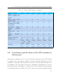
1
Implementation of NFC on an ARM Cortex-M3 Based Platform MARTIN AXELSSON KTH Information and Communication Technology Degree project in Communication Systems Second level, 30.0 HEC Stockholm, Sweden Implementation of NFC on an ARM Cortex-M3 based platform Degree project, in electronic and computer systems, second level Martin Axelsson Stockholm, 2011-10-21 Abstract Syntronic, a medium sized company in Sweden, has a multi-purpose platform, Midrange, that is used in many projects. The library for the platform is solid, but can be even bigger. This project will evaluate if NFC is a good solution for one of their biggest applications for Midrange; a charging pole for electrical cars. The second, and main, task is to create a good set of NFC functions that can be added to the library. To be able to create and test the functions and the possibilities a set of hardware are needed. The hardware should be evaluated, chosen, bought and tested within the project. The Midrange platform was connected to a breakout board for NFC. The board hosted a module from NXP; PN532. The breakout board was connected via RS-232 to the platform after considering different interfaces. After learning the functions of the platform it was time to start writing the NFC library. The library was written as an API and the intention was that it should be very easy to use. The software written in this project is very easy to use and even to modify. The performance of the breakout board was also good and the antenna on the board is recommended for most of the applications. Today, there is no indication for Syntronic to replace their RFID in the charging pole and use NFC instead. The functionality that NFC would add to the pole compared to RFID is more security and the ability to send all kind of data. The ability to pay over NFC in the pole was far too complicated to fit within this project. i Preface This thesis was the closure of a five year study period in Stockholm. The years have been filled with a lot of fun and of course; even more hard work. The thesis is also the closure of, for this time at least, my 17 years of continuous work in school. I will thank some important people for making this thesis possible to complete. First, I want to thank everyone at Syntronic for their hospitality, support and kindness. Joel Nilsson has been a fellow student for all my years in Stockholm and has also been a big support throughout this thesis. The, perhaps biggest, support has come from my fiancée Therése Olsson. I hope that you will enjoy this report as much as I did when doing this thesis. Have a nice reading! Martin Axelsson ii Contents 1 Background 1.1 1 Implementation of NFC on an ARM Cortex-M3 based platform . . 2 History 1 3 2.1 IFF – Identification Friend or Foe . . . . . . . . . . . . . . . . . . . 3 2.2 RFID – Radio Frequency IDentification . . . . . . . . . . . . . . . . 4 2.3 Smart card 5 . . . . . . . . . . . . . . . . . . . . . . . . . . . . . . . 3 NFC in general 7 3.1 NFC payments . . . . . . . . . . . . . . . . . . . . . . . . . . . . . 7 3.2 The standards . . . . . . . . . . . . . . . . . . . . . . . . . . . . . . 8 3.3 NFC competitors . . . . . . . . . . . . . . . . . . . . . . . . . . . . 10 4 NFC modules 13 4.1 Comparison of NXP’s modules . . . . . . . . . . . . . . . . . . . . . 14 4.2 Conclusion and decision of the NFC module in this project . . . . . 17 5 The hardware used in this project 21 5.1 NFC hardware . . . . . . . . . . . . . . . . . . . . . . . . . . . . . 21 5.2 Platform . . . . . . . . . . . . . . . . . . . . . . . . . . . . . . . . . 21 5.3 Connecting the hardware . . . . . . . . . . . . . . . . . . . . . . . . 22 5.4 Additional hardware and tags . . . . . . . . . . . . . . . . . . . . . 23 iii CONTENTS 6 Details about the used NFC module 6.1 27 NFC message passing . . . . . . . . . . . . . . . . . . . . . . . . . . 27 7 The implementation phase 31 7.1 Learning the platform . . . . . . . . . . . . . . . . . . . . . . . . . 7.2 Start to talk to the NFC breakout board . . . . . . . . . . . . . . . 32 7.3 Reading passive tags with the Midrange platform . . . . . . . . . . 33 7.4 Talking to the computer from the platform over NFC . . . . . . . . 35 7.5 An application for a charging pole for electrical cars . . . . . . . . . 36 7.6 Generalising the code . . . . . . . . . . . . . . . . . . . . . . . . . . 37 7.7 Measuring antenna performance . . . . . . . . . . . . . . . . . . . . 39 8 Results 31 43 8.1 Software . . . . . . . . . . . . . . . . . . . . . . . . . . . . . . . . . 43 8.2 Antenna performance . . . . . . . . . . . . . . . . . . . . . . . . . . 45 9 Conclusions and further work 47 9.1 Conclusions . . . . . . . . . . . . . . . . . . . . . . . . . . . . . . . 47 9.2 Further work and recommendations . . . . . . . . . . . . . . . . . . 49 Bibliography 51 Appendices A Outputs from both NXP’s software and from the project’s software B Supported functions by PN532 iv 57 63 List of Figures 3.1 A typical flow over the usage of NFC . . . . . . . . . . . . . . . . . 8 4.1 The NFC module PN532 . . . . . . . . . . . . . . . . . . . . . . . . 19 5.1 The NFC breakout board . . . . . . . . . . . . . . . . . . . . . . . . 22 5.2 The Midrange platform . . . . . . . . . . . . . . . . . . . . . . . . . 23 5.3 The contents of the NFC-kit delivered by SCM Microsystems . . . . 24 5.4 All hardware used in this project for active communication . . . . . 25 6.1 The form that the normal commuication follows . . . . . . . . . . . 27 6.2 The beginning of all messages . . . . . . . . . . . . . . . . . . . . . 28 6.3 The message structure . . . . . . . . . . . . . . . . . . . . . . . . . 28 6.4 Special messages for NXP PN532 . . . . . . . . . . . . . . . . . . . 29 6.5 The wakeup sequence for PN532 . . . . . . . . . . . . . . . . . . . . 30 7.1 The beginning of the main file . . . . . . . . . . . . . . . . . . . . . 33 7.2 The setup used to debug the NFC commands . . . . . . . . . . . . 34 7.3 The message sent to poll for passive devices . . . . . . . . . . . . . 35 7.4 A flowchart for the NFC mode selection in the main file . . . . . . . 37 7.5 A flowchart for the NFC target mode . . . . . . . . . . . . . . . . . 38 7.6 A flowchart for the NFC initiator mode . . . . . . . . . . . . . . . . 7.7 The three tested shields for the antenna test . . . . . . . . . . . . . 42 8.1 The double plastic shield . . . . . . . . . . . . . . . . . . . . . . . . 46 41 v LIST OF FIGURES 9.1 The two NFC boards on top of each other . . . . . . . . . . . . . . 50 A.1 The output from the software on Midrange acting as initiator . . . 58 A.2 The output from NXP’s software acting as target . . . . . . . . . . 59 A.3 The output from NXP’s software acting as initiator . . . . . . . . . 60 A.4 The output from the software on Midrange acting as target . . . . . vi 61 List of Tables 3.1 Comparison of NFC’s competitors . . . . . . . . . . . . . . . . . . . 10 4.1 NXP’s NFC modules . . . . . . . . . . . . . . . . . . . . . . . . . . 15 4.1 NXP’s NFC modules (continued) . . . . . . . . . . . . . . . . . . . 16 4.1 NXP’s NFC modules (continued) . . . . . . . . . . . . . . . . . . . 17 6.1 Description of the words used in the message structure . . . . . . . 28 8.1 Implemented functions . . . . . . . . . . . . . . . . . . . . . . . . . 44 B.1 All commands supported by NXP’s PN532 . . . . . . . . . . . . . . 63 B.1 All commands supported by NXP’s PN532 (continued) . . . . . . . 64 vii viii Chapter 1 Background Near Field Communication or NFC(1) is a technology with a, most likely, bright future. It is said that NFC should move the daily life to the next level by enabling the Internet of things(2). NFC is a multi-purpose technology; the most common usages are payments, tickets and identification. Recently in the Mobile World Congress 2011 in Barcelona NFC was one of the big trends in the mobile world in the near future(3). NFC has been included in mobiles earlier, especially in the Asia-region, but it is just recently that almost all major manufacturers claims that they will include it in the most of their upcoming phones(4). 1.1 Implementation of NFC on an ARM CortexM3 based platform In this project NFC should be included and implemented on an existing platform that is provided by Syntronic(5) in Sweden. The platform is called "Midrange" and is used in many projects delivered by Syntronic. The Midrange hosts a CortexM3(6) processor and many connections to peripherals. The implementation should firstly focus on to determine if NFC is a good solution in a charging pole for 1 CHAPTER 1. BACKGROUND electrical cars and secondly on writing generic and useful code. After this project Syntronic will evaluate NFC with this thesis as a decision base. The implementation should therefore be prepared for other projects by making the code as generic as possible. 1.1.1 Requirements on the hardware and the software within this project In this project NFC should be implemented on a multi purpose platform. The platform holds several functional blocks that can be adapted to the customer and the application. Syntronic wants a new functional block; with NFC. The block should be similar to an application programming interface (API)(7). The project will also investigate different NFC modules and other hardware, a complete list of the tasks for the project can be found in the list below. • Make a substantial study about NFC in general; to be able to solve the project’s problems • Investigate different NFC vendors and modules • Choose the hardware best suited for this project • Investigate different needs for diverse applications • Determine if NFC is worth to implement in a charging pole • Implement a generic software that can act as a solid start in many applications • Make recommendations regarding both software and hardware in upcoming projects 2 Chapter 2 History Near field communication has evolved from several other technologies, the nearest cousins are RFID and Smart card. 2.1 IFF – Identification Friend or Foe The Germans was first with developing an IFF system(8) during the World War II, their version was very simple but not so reliable. The system was used to identify if incoming airplanes was a friend or a foe and used only existing radar technology. The German planes modified the backscattered radar signal by rolling the plane; this changed the polarisation of the signal and enabled identification of the planes by the radar operator. This worked well in the beginning, but was eventually discovered by the enemies. The British air force invented a similar version to the German’s IFF; they placed active transponders on each of their plane. The active transponder used the radiated radar signal and sent a modulated signal back. The active transponder made a more distant identification possible, but the first version needed a mechanically tuning of the frequency used by the different radar frequencies. The British IFF system evolved during the war and made it possible for the British forces to apply 3 CHAPTER 2. HISTORY up to six different codes to the modulation later in the war. The different modes provided additional information about the plane to the ground station. Some has speculated that a better IFF system in Pearl Harbor could have prevented the catastrophic events in 1941. A radar station near Pearl Harbor identified the incoming planes, but dismissed them as Americans(8). The IFF systems are still used, but are far more complicated nowadays. However, IFF is the ancestor to NFC. 2.2 RFID – Radio Frequency IDentification RFID(9) was developed from the IFF system and it has been prophesied to be one of the most important technologies in our modern world for a long time. The technology has not taken off as early as experts thought, nowadays it is not even as popular as they expected. RFID uses radio in different frequencies to mainly identify objects. From the beginning of the 90’s RFID was meant to in a near future to replace the bar codes used everywhere(10), as one can discover even now this has not happened yet. That is just another failure of the plans for RFID(11), but it will however probably replace the bar codes someday. The RFID technology has, as mentioned before, different frequencies that is chosen depending of the intended implementation. RFID needs two components to work, one reader and one transponder. The transponder is different depending on the usage as well, it can be passive, active or even printed on paper(12), and is referred to as a “tag”. The frequency range is from 125 KHz to 5,8 GHz, the lower frequencies often uses inductive coupling and the higher ones often using radiative coupling. With an inductive coupled system the tag operates within the induced magnetic field from the reader. Often the induced field provides the tag with all the needed power to the tag. This makes it possible to construct very simple tags, as mentioned before these could even be printed on paper or plastic. The RFID tags can also have different power methods: passive, semi-passive and active. The passive version powers up and backscatter a signal using the power emitted from the reader. Semi4 2.3. SMART CARD passive uses a battery to power the circuits on the tag, but uses the emitted energy from the reader to backscatter the signal. An active tag has power on-board both to the circuits and to transmit the radio signal that is sent back to the reader. Of course the different power modes have different usages and prices. The passive version is the cheapest and often the most short ranged. RFID has been successful in a lot of implementation and it is still an active topic in research, despite its age of around half a century. RFID is today most common in animal tracking, transport tracking, car tolls and access systems. 2.3 Smart card Smart cards are common today since the card issuers have started to replace the magnetic stripes on credit cards with a smart card implementation. A smart card has a small microprocessor embedded on the card and open contact areas(13). The microprocessor is activated when the card is inserted in the reader. The microprocessor also hosts a memory where the card’s encrypted details are stored; these are used instead of the old magnetic stripe. Smart cards have also evolved and today it exists contactless smart cards(14). They work as regular smart cards but wirelessly over a very short range. Smart cards and NFC has been tight coupled in the technological evolution. In fact, one can say that RFID and smart cards has been combined into NFC. The security functions in security critical implementations of NFC are the most visible heritage from smart cards. 5 6 Chapter 3 NFC in general NFC will most likely be very common in a quite near future. As mentioned in chapter 1 on page 1, all major cellphone manufacturer have almost promised to release cellphones equipped with NFC hardware. NFC will probably replace today’s payment methods sometime in the future. The payments is not the only upcoming implementations of NFC. The idea from mainly the cellphone manufacturer area is that NFC will enable more convenient and additional services. All services will be included in the cellphone that every user will have, a realistic flow in the future is illustrated in figure 3.1 on the next page. The flow can be a business trip or similar. The NFC device can be used to pay with, as a passport, instead of tickets, to get more information at a information poster, to easily pair a wireless headset and to exchange all kind of data between two devices. 3.1 NFC payments NFC is not a new technology, it has been prophesied for a long time. The most common application for it is the payment application. The problems that have been slowing down NFC from being well spread today is especially two. The first is the trust issues(15); is the user willing to give out all its credentials? Does the user rely on the cellphone manufacturer or the operator? The security critical functions 7 CHAPTER 3. NFC IN GENERAL Figure 3.1: A typical flow over the usage of NFC need something called a secure element. This is very similar to the existing SIM card in today’s cellphones and can be implemented in both hardware and software. The secure element leads into the next problem for the spreading of NFC; who will own the secure element? The operators will include it into the existing SIM cards, the manufacturer also want to have control over the secure element but embedded in the phone. Nowadays even more players want to act and own the secure element; the credit/debit card issuers and the manufacturer of the phone’s operating system, i.e. Google with its Android system. These two problems are urgent to solve to enable the spread of NFC. A solution might be on its way; Google is such an innovative and big company and they have just decided to not care about the operators or the card issuers. Several, especial payment, tests is ongoing right now, but Google has the biggest test. They have launched tests in New York City and San Francisco, but will later expand it to more cities(16). 3.2 The standards NFC is such an evolving and prophesied technology and therefore a lot of standards are created by several standardisation organisations. In this report the focus is 8 3.2. THE STANDARDS on the standards defined by the International Organization for Standardization (ISO)(17). 3.2.1 ISO 14443 ISO 14443(18) defines the standard for contactless integrated circuit cards or proximity cards. It is the evolution of the regular smart cards; this version works without any contact but with a very short range. ISO 14443 has also some minor standardisations under its name; e.g. 14443-A, 14443-B. ISO 14443 is in fact not a special NFC standard, but NFC started with the contactless smart cards that is described in this standard. Since ISO 14443 defines the contactless smart cards it includes the wireless communication, such as RF protocol. Many NFC devices can imitate ISO 14443 by emulating the card, the reader then determine the NFC device as a contactless smart card. The purpose for this is that NFC devices could in the future store all kind of cards in the same device. 3.2.2 ISO 18092 ISO 18092(19) is the first standard written especially for NFC. It covers the most parts involved in a complete NFC system. ISO 18092 defines NFCIP-1, which deeply describes the interface and protocol used in an 18092-certified NFC system. NFCIP-1 carries the definition of the different modes (active, passive), RF protocol interface, general protocol flow, RF collision avoidance, transport and data exchange protocol. All parts of NFCIP-1 is important when designing a NFC device, if it does not follow NFCIP-1 it might not be compatible with other devices. 3.2.3 ISO 21481 The standard ISO 18092 was the first pure NFC standard and NFCIP-1 in that standard defined the interface and protocol used in an NFC system. The continuing of NFCIP-1 is called NFCIP-2(20) and it is defined in ISO 21481. NFCIP-2 9 CHAPTER 3. NFC IN GENERAL contains much less definitions compared to NFCIP-1; NFCIP-2 has information about external RF field threshold and detection, mode selection and RF detection and initial RF generation. Like NFCIP-1 these are important when designing devices that should be compatible with the ISO 21481 standard. 3.3 NFC competitors NFC has some similar technologies to compete with. These has become more interesting since the problems described in section 3.1 on page 7. Some scientists has grown tired about NFC, that it not can get its real breakthrough. Therefore some competitors has arisen, these can be compared in table 3.1(21). Table 3.1: Comparison of NFC’s competitors Property NFC Bluetooth 2.1 Bluetooth low IrDa energy (BLE) Network type peer-to-peer Point-to- Point-to- multipoint multipoint ∼ 30 m ∼ 50 m up to 1 m Range up to 0,1 m Speed 424 Kbit/s Set-up time < 0,1 s <6s Security yes, yes, software hardware 2,1 Mbit/s peer-to-peer ∼ 200 Kbit/s up to 16 Mbit/s < 3 ms 0,5 s yes, software no, and secure card except IRFM IC Communication active-active, active-active active-active active-active Low moderate/low moderate/low low Frequency 13,56 MHz 2,4-2,5 GHz 2,4-2,5 GHz not applicable Power > 15 mA < 30 mA < 15 mA not available mode active-passive Costs con- sumption The most widespread competitor is bluetooth 2.1, but it does have some security issues. Bluetooth low energy (BLE) is the newest of the one in table 3.1 and maybe also the biggest competitor. BLE has not as good numbers as NFC, but it is the 10 3.3. NFC COMPETITORS closest and best competitor to NFC. All of these competitors are functional over a longer distance compared to NFC. This seems to be an advantage, but in some applications it might be a problem. NFC is intended to work over a very short range due to its, often, security critical applications. The longer the range of the communication is the more threats are directed towards it. This, the low power consumption and the extremely short set-up time might be the biggest advantages of NFC. 11 12 Chapter 4 NFC modules NXP is the world-leading manufacturer of NFC devices; in fact they currently almost have a monopoly in the NFC world(22). However, Broadcom (by their acquisition of Innovision)(23), Infineon(24) and Samsung has their modules in their starting blocks(25). In the beginning of the project the manufacturers of NFC was identified. Quickly it was discovered that by focusing on readers, NXP was the only choice of the NFC modules. There is a lot of manufacturers of the tags that the readers and modules can interact with, the market for this is much bigger and more shared between different companies. Some microprocessor and software developers have tried to make the implementation of NFC easier by creating their own PCB. The boards often host a microprocessor, an antenna and a connection interface. This is done as a service to other companies, so that they can create NFC products more easily, by integrating all needed parts in one PCB and a more high-level programming language. Most of these PCBs contains either of NXP’s modules. NXP has two kinds of NFC modules, one kind is the NFC transceiver that only includes the NFC functionality, the other kind is similar to the transceiver but it also hosts a microprocessor. The microprocessor version is called NFC controller and the microprocessor on-board is an 80C51. The NFC controllers are available on the PCBs mentioned before and these boards host dual microprocessors. The additional microprocessor enables more high-level programming and additional communication protocols compared to the NFC controller. 13 CHAPTER 4. NFC MODULES 4.1 Comparison of NXP’s modules NXP has two categories of NFC modules, transceivers and controllers. A comparison of the different modules can be studied in detail in table 4.1 on the next page. The table summarizes the most parts that needs to be compared when choosing the NFC module. The first part is about the interface that the module should be connected with; UART(26), I2 C(27), SPI(28), 8 bit parallel(29) or USB(30). SWP is the single wire protocol(31) and it is used together with the secure element mentioned in section 3.1 on page 7. S2 C is also a special interface for the secure element, but it uses two wires; one for transmitting and one for receiving. In many applications a more high-level language (i.e C++ or Java) is wanted, this demands a CPU that can translate the commands to the NFC module. NXP has included CPUs in three of the modules in table 4.1 on the next page. The memories (RAM, ROM and E2 PROM) are only available on the modules with a CPU. The standards supported by the different modules diverge, which standard that is wanted depend on the application. The different standards is described in more detail in section 3.2 on page 8. FeliCa and MIFARE are Sony’s respectively Philips’/NXP’s own version of the ISO 14443. They are both used frequently in different ISO 14443 implementations. ISO 15693 is the standard about "vicinity cards"; this is a technology with a greater distance (1-1,5 m) but with a lower bandwith. The applications for ISO 15693 is much fewer than for NFC. As mentioned in section 3.2.1 on page 9, many NFC devices can emulate existing cards. The cards that can be emulated are common in public transportation, payment and identification systems. The cards used in such systems are often of different types, and not all modules support all of them, the supported systems for each module can be found in table 4.1 on the facing page. The modules also support various baudrate when communicating over NFC, the baudrates ranges from 106 kbit/s to 848 kbit/s. The security functions is often demanded by some applications. Therefore, some additional security functions are supported by most of the NFC modules. MIFARE classic is a MIFARE with a memory and additional security functions, it is developed by Philips/NXP. The smart card controller is often the one controlling the secure 14 4.1. COMPARISON OF NXP’S MODULES element, and there are mainly two interfaces for the communication; S2 C or SWP. The modules with a CPU on board have a firmware that can be updated to support more functions or restored when the device is not functional correct. The last part of table 4.1 compares the power consumption and its functions and also the physical characteristics of each module. The power consumption part is very important when choosing the right module. This is because the module often should be embedded in a mobile device with strictly limited power supply. The cost is if possible for just one module, if the order is big the price difference between each module is very small. The price is fetched from a price comparing site(32) and the availability has not been considered. Table 4.1: NXP’s NFC modules NFC Transceivers Product features Operating PN511 PN512 distance NFC Controllers PN531 PN532 PN533 PN544 Up to 100 depending on mode, coil... typical [mm] Interfaces UART [Mbit/s] Up to Up to Up to Up to Up to 0,4608 1,228 1,228 1,228 1,228 1,228 400 k / 400 k / 400 k 400 k - 3,4 M 3,4 M up to 5 up to 5 up to 5 up to 5 - 8 8 bits parallel inter- yes (only yes (only - - - - face QFN40) QFN40) USB 2.0 (full speed) no no yes no yes no SWP interface - - - - - yes S C interface yes yes yes yes yes yes CPU no no 80C51 80C51 80C51 HT80C51- I2 C interface [bit/s] SPI interface 400 k /3,4 M [Mbit/s] interface 2 MX RAM/ROM/E PROM 2 [bytes] - 1 k/32 k/- 1 k/- k/40 1,2 k/44 5 k/128 k/- k/52 k RF interface Continued on next page 15 CHAPTER 4. NFC MODULES Table 4.1: NXP’s NFC modules (continued) Product features Carrier PN511 PN512 PN531 frequency PN532 PN533 PN544 13,56 [MHz] Standard and Protocols ISO 18092 peer-to- yes yes yes yes yes yes read- yes yes yes yes yes yes read- no yes no yes yes yes FeliCa reader/writer yes yes yes yes yes yes ISO no no no no no yes FeliCa, FeliCa, FeliCa, FeliCa, FeliCa, FeliCa, peer (active/passive) ISO 14443-A er/writer ISO 14443-B er/writer 15693 read- er/writer Card emulation ISO14443- ISO14443- ISO14443- ISO14443- ISO14443- ISO14443A, MI- FARE A, MI- FARE A, MI- FARE A, MI- FARE A, MI- FARE A-B-B’, MIFARE NFC baudrate [kbit/s] 106/212/ 106/212/ 106/212/ 106/212/ 106/212/ 106/212/ 424 424 424 424 424 424/848 Security features MIFARE classic yes yes yes yes yes yes Interface S2 C S2 C S2 C S2 C S2 C S2 C/SWP to smart card controller Additional product information Embedded firmware no no yes yes yes yes Integrated LDO volt- no no no yes no yes Low battery mode no no no yes no yes Battery off mode no no no no no yes Supply voltage [V] 2,5...3,6 2,5...3,6 2,5...4,0 2,7...5,5 2,5...3,6 2,3...5,5 Min. 1,6 1,6 1,6 1,6 1,6 1,65...1,95 - - 4,2...5,5 - 4,2...5,5 - age regulator host interface voltage [V] USB bus power supply Continued on next page 16 4.2. CONCLUSION AND DECISION OF THE NFC MODULE IN THIS PROJECT Table 4.1: NXP’s NFC modules (continued) Product features PN511 PN512 PN531 PN532 PN533 PN544 no no yes yes yes yes mode 5 5 10 5 12 3 mode 10 10 30 25 30 50 60 60 60 60 60 60 -25...+85 -25...+85 -25...+85 -25...+85 -25...+85 -25...+85 0,85 0,85 0,85 0,85 0,85 0,8 Package size [mm] 5x5 / 6x6 5x5 / 6x6 6x6 6x6 6x6 4,5x4,5 Package type HV- HV- HV- HV- HV- TF- QFN32 QFN32 QFN40 QFN40 QFN40 BGA64 Supply voltage for secure element integrated Power down (typical) [µA] Power down with RF level detector on [µA] Transmitter supply current (typical) [mA] Temperature range [ C] ◦ Package thickness [mm] / Cost [$] 4.2 HV- / HV- QFN40 QFN40 Less Less Less Less Less Less than 5 than 5 than 9 than 15 than 15 than 11 Conclusion and decision of the NFC module in this project The purpose of this project is to create and show a prototype where NFC should be involved. Since the prototype should be broad the module should have as much possibilities as possible. The broadness of the project has also made that there are no demands on the cost/unit or the power consumption. All modules are also in perspective cheap and consume very little power. The requirement on the module is consequently that it should at least have the most popular standards within 17 CHAPTER 4. NFC MODULES the NFC area. The modules named PN512, PN532, PN533 and PN544 all have ISO 14443-A/B, ISO 18092, MIFARE and FeliCa. These four modules answer the requirements of the most popular standards. In this project the NFC module should be connected to a Cortex-M3 processor, which has many communication interfaces and is more described in section 5.2 on page 21, both kind of modules can therefore be used. The microprocessor available in some of the modules enables a more high-level of communication between the module and the Cortex, this is desirable for this project. The project will use the programming language C to do the programming and for this a module with a CPU is needed. The modules that meet both the requirements so far are all of these mentioned above except PN511 and PN512. When it comes to the communication protocols available on the three modules that still are an option there are some differences. In PN533 NXP has focused on implementing USB, this module has neither I2 C nor SPI. The platform used in this project has the possibility to use an USB connection, but the other serial interfaces are more preferable. The single USB connection on the platform is used in many other applications, therefore any other connection is more preferable. With that choice the available modules are only two, PN532 and PN544. The differences of the two modules are small; PN544 has a different microprocessor from the same family, supports ISO 15693 and has more security functions. ISO 15693, which also is called vicinity card and described shortly in section 4.1 on page 14, is not a target for this project and the feature is hence not requested in this project. The project should also not implement any advance security functions and therefore the additional security functions in PN544 are not needed. All this leads to the conclusion that the PN532 is the best option for this project. PN532, and all other PN5XX devices from NXP, is made to be embedded in small and mobile devices. The module has an area of six by six mm, the module hosts on this area 40 pins. All pins are placed on each edge of the squared package, which means that each side has ten pins. To mount PN532 on a board by hand would be very difficult, which could be obvious by looking at picture 4.1 on the facing page. The module require an antenna to be able to read tags and other devices, the antenna is not included in the package. NXP provides documentation on how 18 4.2. CONCLUSION AND DECISION OF THE NFC MODULE IN THIS PROJECT to both dimension and match the antenna. To avoid both mounting the module by hand and making an own antenna, a breakout board from microBuilder.eu(33) was chosen. The breakout board is also much cheaper than to order an own board from a PCB manufacturer and it can be delivered directly. Now, the project had the possibility to create a very cheap board at KTH, but then the module needed to be soldered by hand. The solution with the breakout board seemed to be perfect for this project since it is only a test and an evaluation of NFC that should be created in a short period of time. Figure 4.1: The NFC module PN532 19 20 Chapter 5 The hardware used in this project 5.1 NFC hardware The hardware chosen to implement Near Field Communication in this project is, as mentioned in section 4.2 on page 17, a board from microBuilder.eu. The board is developed to be used in small and simple projects. The purpose is that small projects, and even for private usages, quickly can get started with an open-source hardware that is manufactured in the most cost-effective way. The board hosts everything needed to get started with NFC. It has several connection protocols; UART, SPI and I2 C. The antenna needed to read tags and to communicate with other NFC devices is also integrated in the PCB. The connections on the board is easy to connect to by using standard 0,1 inch header pins. The board can be examined in picture 5.1 on the following page below. 5.2 Platform The platform used in this project is a platform developed within Syntronic. The platform was developed to be used in projects where both performance and cost are on a medium level; therefore the platform is called "Midrange". The Midrange is 21 CHAPTER 5. THE HARDWARE USED IN THIS PROJECT Figure 5.1: The NFC breakout board built around an ARM Cortex-M3 processor and the connections on the board has several communication protocols; UART (RS232), CAN, I2 C, SPI, USB, Ethernet and RS485, see figure 5.2 on the next page. The Midrange is well suited in many projects because its versatile functionality combined with the short start-up phase. Therefore it is extra well suited for projects in the medium level that should be finished within a short period of time. 5.3 Connecting the hardware The Midrange is, as mentioned in the previous section, versatile when it comes to the communication protocols. The breakout board with the module from NXP has also several communication protocols; UART, SPI and I2 C. The Midrange has several ports that are implementing UART; since this project do not have a sharp implementation where it should be used it is good to have as much free ports as possible available. To enable more free ports UART was chosen, it is also the most simple communication protocol available on the breakout board. The NFC board require however not the usual UART connection, it must be connected to the TTL-level of the UART port. The Midrange has also these ports available through the standard 0,1 inch connector, so this was not a problem. How the breakout board is connected to the platform is explained more in chapter 7 on page 31. 22 5.4. ADDITIONAL HARDWARE AND TAGS Figure 5.2: The Midrange platform 5.4 Additional hardware and tags The project needed more hardware than just the Midrange platform and the NFC breakout board to complete the tasks and to be able to show some results. The additional hardware that was needed was both tags, to be able to test the passive communication, and another NFC device needed for testing the active communication. The tags can be bought from almost everywhere and are also often cheap. Another NFC device is harder to get for a reasonable price. It exists cellphones with NFC compatibility, but that should have been too expensive and also harder to control. Therefore a desktop reader seemed to be the best choice for this project. A kit from SCM Microsystems(34) was found, it included a desktop 23 CHAPTER 5. THE HARDWARE USED IN THIS PROJECT reader and three different tags, for just €39,95 and is depicted in figure 5.3. The tags were of NFC Forum Type 1, 2 and 4(35) and manufactured by SCM. The desktop reader sported a NXP PN531 module; this made it possible to use SCM’s, NXP’s(36) or libNFC’s software(37). SCM’s free software included only the feature to read the tag and then open the website stored on the tag, all through a simple GUI. LibNFC is an open-source software that provide a library for many NFC functions. The library is not developed by a company and the support for it is not the best. NXP’s software is the easiest to use together with the desktop reader in the kit from SCM. The source code for the software is also available, if the user want to modify it. (a) The three tags included in the NFC-kit (b) The desktop reader, SCM’s SCL3710 Figure 5.3: The contents of the NFC-kit delivered by SCM Microsystems 24 5.4. ADDITIONAL HARDWARE AND TAGS Figure 5.4: All hardware used in this project for active communication 25 26 Chapter 6 Details about the used NFC module The best module for this project was NXP’s PN532, which was superior the other modules found in chapter 4 on page 13. There was a quick review of PN532 in chapter 4 on page 13, but in this chapter there will be more details about it. 6.1 NFC message passing The message passing has a predetermined structure where some parts are defined by the NFC standards and others by NXP. It also follows a specific form, this form can be seen in figure 6.1. Figure 6.1: The form that the normal commuication follows All messages start with a preamble consisting of a byte with zeros, then a command 27 CHAPTER 6. DETAILS ABOUT THE USED NFC MODULE start code consisting of a byte of zeros and a byte of ones are following. The structure for the beginning of the messages can be seen in figure 6.2. Figure 6.2: The beginning of all messages All elements of the messages are divided in bytes and also all commands are represented by one byte. The full structure is depicted in figure 6.3 and explained in table 6.1 Figure 6.3: The message structure Table 6.1: Description of the words used in the message structure PRE Preamble START Command start START Command start LEN Length of data, number of bytes in D[ ] + COM + DCS LCS Length checksum, LEN + LCS = 0x00 DIR Direction, 0xD4 = Host to module, 0xD5 = Module to host COM Command, one byte with the command code D[ ] Data array, the array of data divided in bytes DCS Data checksum, the sum of D[ ] + DIR + DCS = 0x00 POST Postamble, message ended 6.1.1 Sending messages The PN532 cannot send anything to the host by its own responsibility, it can only reply to commands that the host sends to it. To send a message to PN532 the host 28 6.1. NFC MESSAGE PASSING should follow the structure in figure 6.1 on page 27 and 6.3 on the preceding page. It is also important to listen for the acknowledge message after a sent message, since it indicates if PN532 successfully understood the command. 6.1.2 Receiving messages When the module replies to the host it modifies the command byte by adding the value 0x01 to the command code. Therefore all command codes from the host to PN532 are even and all replies from PN532 are odd. After receiving a correct message the host can optionally send an acknowledge message. A negative acknowledge after a received message leads to a retransmission of the last message from PN532. 6.1.3 Special messages The NXP PN532 has some special messages that not follows the regular structure described in figure 6.3 on the facing page. ACK and NACK For PN532 it exist two special messages, acknowledge and negative acknowledge messages, used as a handshake mechanism between the host and the module. Acknowledge is used as positive handshake and negative acknowledge as a negative handshake. A NACK message always lead to a retransmission of the latest message. (a) Acknowledge message (b) Negative acknowledge message Figure 6.4: Special messages for NXP PN532 29 CHAPTER 6. DETAILS ABOUT THE USED NFC MODULE Wakeup message To initialise and wakeup the NFC module a special wakeup message must be sent. The module always starts in sleep mode and does not start correctly before it has received the wakeup sequence. The wakeup sequence also configures the module with different modes. The bytes in the wakeup sequence used in this project are depicted in figure 6.5. Figure 6.5: The wakeup sequence for PN532 30 Chapter 7 The implementation phase The implementation part was started a little bit early compared to the project plan since the hardware comparison was so dominant by NXP. 7.1 Learning the platform The project has not developed anything on the Midrange platform before; therefore it was required to learn the platform thoroughly before starting to write NFCspecific code. The platform can be implemented both with and without a real time operating system. In this project it was chosen to use the one most common in Syntronic’s projects; with a version of FreeRTOS(38) running on the core. Roughly two weeks were accumulated to learn the platform, this process included the basics on the platform and in FreeRTOS. Firstly the environment needed to be setup; it used the standard development environment Eclipse(39), the version was Ganymede(40) and the debugger was Sourcery G++ Lite 2009q1-203 for ARM(41). The environment was runned on an Intel P4 machine(42) with Windows XP(43). The Midrange uses a standard USB-port to power the platform (an external power supply can also be used) and a JTAG(44) to flash the core with new software. The debugger, OpenOCD debugger(44), was the hardest part to get running in the beginning; the combination of the JTAG and the configuration of Eclipse were 31 CHAPTER 7. THE IMPLEMENTATION PHASE hard to get right. When the debugging was working and the environment was properly setup it was time to test some simple tasks on the platform. The aim for the simple tasks was to test features that could be used later on in the project. Some of the tested functions were control the LEDs, try the scheduling and task priorities, semaphores, print text on serial ports and also some interrupts. 7.2 Start to talk to the NFC breakout board When the project mastered the environment and the platform it could connect the NFC breakout board to the Midrange platform. The NFC board was, as described in section 5.3 on page 22, connected to the TTL-level of one of the UART ports. In the beginning the focus was to understand the messages that was replied by the breakout board. To be able to initialize the NFC module and the embedded microprocessor a special wakeup command must be sent, see section 6.1.3 on page 30. This wakeup command contains different settings for the microprocessor and some NFC specific functions. A flowchart of the beginning of the main file can be examined in figure 7.1 on the facing page. 7.2.1 Debugging with NFC Debugging with the NFC functions was discovered to be hard. The normal debugging via the JTAG was not possible since the microprocessor in the NFC module timeouts if it not receives the next byte within a short period of time. For debugging NFC an, on beforehand, undiscovered method could be used; the COM-port belonging to the TTL-level UART connected to the breakout board. By connecting the COM-port to a computer and a terminal application, the commands sent from the Midrange to the NFC board could be debugged. The setup is illustrated in figure 7.2 on page 34. The bytes sent the other way could however not be debugged. 32 7.3. READING PASSIVE TAGS WITH THE MIDRANGE PLATFORM Figure 7.1: The beginning of the main file 7.3 Reading passive tags with the Midrange platform In the NFC-kit (see section 5.4 on page 23) there was three passive tags. The tags were of three different types; NFC Forum enabled, NFC Forum Type 2 and Type 4 tag, mentioned in section 5.4 on page 23. The three tags have different ID and length of the ID, the embedded memory variates also among the three tags. It is easier to start reading passive tags instead of active since passive tags normally just replies with its ID. The other functions often used is read and write to the 33 CHAPTER 7. THE IMPLEMENTATION PHASE Figure 7.2: The setup used to debug the NFC commands embedded memory. To be able to read the passive tags a polling request must be sent to the NFC module from the Midrange. The polling request is easy if the host only need the information of which tag that is present. The command sent to perform the polling is called InListPassiveTarget (command byte: 0x4A), the full command is illustrated and explained in figure 7.3 on the facing page. All other supported commands are listed in the appendix. If the module finds any passive tags it gives it a short ID (0x01 to 0x02) that can be used instead of the full ID for a short period of time. This is useful if the user wants to send a message to tag without using the full ID. The PN532 also replies with the full ID, and other 34 7.4. TALKING TO THE COMPUTER FROM THE PLATFORM OVER NFC bytes stored in the ID block on the passive tags, to the host. The passive type of communication is not that rich of features and also not the scope for this thesis. It was though a good and simple test for testing NFC for the first time. 0xD4 The byte indicating that the command is sent from the host 0x4A The command byte, InListPassiveTarget MaxTg The maximum number of targets that should be initialised by PN532. The module can handle maximum two targets at once BrTy The wanted baudrate to be used, the supported modes are: • 0x00 : 106 kbps type A (ISO 14443 Type A) • 0x01 : 212 kbps (FeliCa polling) • 0x02 : 424 kbps (FeliCa polling) • 0x03 : 106 kbps type B (ISO 14443-3B) • 0x04 : 106 kbps Innovision Jewel tag InitiatorData [ ] Array of data that can be used during the initialisation Figure 7.3: The message sent to poll for passive devices 7.4 Talking to the computer from the platform over NFC The real scope for this project is to implement a solution that uses the active communication enabled by NFC. The active communication involves more features compared to the passive one, the possibilities are also much more with an active communication. The passive communication almost only support the functions mentioned in section 7.3 on page 33 and the active communication have support for almost all kind of wireless communication. However, NFC is not useful in all kind of communication since the poor range and relatively small bandwidth. The structure 35 CHAPTER 7. THE IMPLEMENTATION PHASE of the communication is different from the passive communication; first the link must be established, then data can be exchanged. The two devices exchanging their ID establish the link; each device can only be connected to one link. The link and the communication have two roles, initiator and target; these are similar to the usual master and slave roles but are more equal. It is the initiator that initiates the link establishment. When the link is established the two devices are becoming even more equal, both devices can start to send data and receive data. The NFC message passing is intelligent designed, the design has made it unnecessary to have any send or receive buffer. The design of the message passing is similar to the one in figure 6.1 on page 27. Both devices alter sending and receiving; the initiator sends data and waits for an answer that optionally can contain data from the target. If the target has no data to reply with it just add 0x01 to the command code sent by the initiator. The chain of messages following the structure in figure 6.1 on page 27 is equivalent for both passive and active communication, but normally the chain is longer for the active version. The program written to test this implementation is depicted in figure 7.4 on the facing page and starts with the flowchart in figure 7.1 on page 33. If the active mode and then the target mode is chosen the program will follow the structure in figure 7.5 on page 38. For the initiator mode the respectively structure can be found in figure 7.6 on page 41. 7.5 An application for a charging pole for electrical cars Syntronic have a charging pole for electrical cars in some test cities. There are some functions included in the existing pole, but Syntronic is developing the next generation of the pole. In the next generation they might be interested of using NFC; the most interesting function might be the ability to pay over NFC. Today the payment and identification is done via RFID tag. This has some drawbacks; the payment credentials must be stored somewhere, there is no possibility to lend out the car to the family or to friends and they can pay directly, the payment details must be changed when they are updated and etcetera. 36 7.6. GENERALISING THE CODE Figure 7.4: A flowchart for the NFC mode selection in the main file The payment methods that the big card issuers are using are very complex and secure. This would require a lot of studies in this methods and many of them might not be available to anyone. The hardware for making the payment possible in the charging pole could be the same as in this project. The software for the payment might be the best to obtain from a company that are specialised in payments or directly from the card issuers. The functions written in the software is able to use for payments, if one knows what data are needed to be sent to pursue the payment. The code is also able to replace the existing RFID solution in the charging pole. 7.6 Generalising the code By implementing and testing the active communication almost all important features of NFC was implemented. Syntronic might have an application for NFC, but it will be evaluated first. They think, like many others, that it will be widely used in the future. The purpose for them is to have a solid library for NFC functions 37 CHAPTER 7. THE IMPLEMENTATION PHASE Figure 7.5: A flowchart for the NFC target mode ready and tested, which could be easily embedded in any application. Therefore it is a need of good and general functions in the code. The functions should smoothly be included in any kind of application and be able to send any kind of data. The code should also be simple to understand by using logical names on functions and variables. This could be very useful for a user that do not have sufficient time to gain enough insight into NFC. The user could read this report or use other sources to gain sufficient knowledge about NFC, and therefore get enough information to modify and write new functions for the contemplated application. The need of simple code and already ready routines are important for an another project’s member that just want to use NFC in their implementation, how it works is not important in just that case. The code was written to make things easier for the user of the code. A function that e.g. sends data, takes care of establishment of the communication link and to 38 7.7. MEASURING ANTENNA PERFORMANCE send data, no matter which device that are initiator or target. If the user wants to change something he must go one level deeper, this level is however not that much harder than the highest, but he will need more understanding about NFC. 7.7 Measuring antenna performance The NFC board or a similar version will probably be used in at least one project delivered by Syntronic. The antenna will most likely be embedded in some kind of case in upcoming projects. The performance of the antenna will therefore be important. The antenna type on both the breakout board and the desktop reader is a coil antenna printed on the PCB. They have the exact same shape, but the size of them is different. The area of the antenna on the breakout board is more than eight times the antenna on the desktop reader. Testing if the antenna is powerful enough to read a passive tag through a shield carried out the antenna test. The test could be important when designing the enclosure of the antenna. The range of the antenna is from the beginning very short, therefore it is more interesting to see what is happening when a shield also becomes in between than to measure the distance. Different kinds of shields were tested for the antenna both on the NFC breakout board and the desktop reader. The tested shields were a thick plastic shield (1 cm thick), a metal plate (2 mm) and a piece of cardboard wrapped in aluminium foil, all shields are depicted in figure 7.7 on page 42. These three kinds of shields are considered as possible to be used in the chassis that will be used later, if the reader can read the tag. The plastic shield will probably act more as a obstacle than a shield. The metal and aluminium shields are not grounded and are big compared to the magnetic field, which means that it will not have any gaps. In theory the antenna’s range is decided by several parameters. One of these parameters are dependent of the medium between the reader and the tag; skin depth, δ, shows how much a signal can penetrate different medium. In the skin depth equation (7.1) µ is the magnetic permeability, σ is the electrical conductivity and f is the operating frequency. The equation just gives a hint about range of 39 CHAPTER 7. THE IMPLEMENTATION PHASE the antenna, a full set of parameters of must be considered when designing an enclosure. δ= 40 � 1 πµσf (7.1) 7.7. MEASURING ANTENNA PERFORMANCE Figure 7.6: A flowchart for the NFC initiator mode 41 CHAPTER 7. THE IMPLEMENTATION PHASE (a) The plastic shield compared to a regular USB connector (b) The aluminium foil shield (c) The shield made of some kind of plate Figure 7.7: The three tested shields for the antenna test 42 Chapter 8 Results The results in this project are few; the main purpose for the project was to deliver a building block for NFC on the Midrange platform. The project has accomplished to deliver this on time. 8.1 Software The different software works well together. The only small problem is the establishment of the connection. If the devices not find each other directly the connection will fail. The problem is mainly in the NXP software; it polls for devices only for a few times and then exits if no device was found. 8.1.1 The software on Midrange The software running on the Midrange platform asks in the beginning the user which mode that should be executed. The different modes are passive and active, where active can be as the initiator or as the target. The output from the software can be seen in Appendix A on page 57 and the implemented functions with a short description can be found in table 8.1 on the following page. 43 CHAPTER 8. RESULTS Table 8.1: Implemented functions Function Description Front end functions NFC_interpreter() Interprets a received message, both command and data. NFC_send_ack() Sends an acknowledge message. NFC_send_nack() Sends a negative acknowledge message. NFC_get_firmware() Returns the firmware version of the NFC module. NFC_send_command() Sends a specific command. NFC_send_data() Sends data, 1-256 bytes, takes care of everything regarding the send procedure. NFC_receive_data() Receives and presents any kind of data. Back end functions NFC_command_start() Adds the beginning of each message. NFC_command_end() Adds the ending of each message. NFC_valid_checksum() Validates the checksum of a message. NFC_calc_checksum() Calculates the checksum for a message. NFC_sum_of_data() Accumulates the value of each byte of data. NFC_valid_datd_checksum() Validates the data checksum. NFC_calc_data_checksum() Calculates the data checksum. NFC_check_beginning() Validates the beginning of each message. NFC_check_ack_nack() Validates if a received message is a positive or negative acknowledge. NFC_check_command() 8.1.2 Validates the received command in a message. The software on the desktop reader The desktop reader was used together with a slightly modified version of NXP’s example code. The software starts with a similar choice as in the code written in this project; the user’s choice of active communication as a initiator or a target. The output from the software communicating with the Midrange as a target and as an initiator can be seen in Appendix A on page 57. 44 8.2. ANTENNA PERFORMANCE 8.2 Antenna performance There was some additional time left in the time budget at the end, since the hardware comparison part and some parts of the implementation part became smaller than what was planned from the beginning. The additional time was used to measure the performance of the antenna. The antenna on the breakout board has empirical showed that it is better than the one in the desktop reader. For Syntronic it would be interesting to see how good the antenna performs, especially since it should probably be embedded in a chassis in future projects. Without any shield or obstacles the antennas performed different; the antenna on the breakout board could read a tag from maximum 6,2 cm and the desktop reader from maximum 2,4 cm. When communicating with each other the antennas must be within 2,3 cm. 8.2.1 Thin metal plate The thin metal plate has an unknown compound of some kind of plate. Plate is similar to steel, which is the metal closest to plate that have its characteristics in regular tables, and therefore the chosen values for the magnetic permeability and the electric conductivity are for steel. δP late = � π ∗ 8,75 ∗ 10−4 1 = 2,13 µm ∗ 5,9 ∗ 106 ∗ 13,56 ∗ 106 (8.1) The antenna on the breakout board was not able to read a tag through the plate shield. The same result was achieved with the desktop reader; it was also unable read the tag. 8.2.2 Aluminium foil wrapped cardboard δAluminium = � π ∗ 1,257 ∗ 10−6 1 = 23,1 µm ∗ 3,5 ∗ 107 ∗ 13,56 ∗ 106 (8.2) 45 CHAPTER 8. RESULTS The chances for reading a tag through the cardboard wrapped with aluminium foil were better when just looking at the skin depth. However, none of the two antennas were able to read a tag through this shield. 8.2.3 Thick plastic plate The skin depth for plastic is not applicable since plastic is an insulator. If the properties of plastic is used in the skin depth equation the result will be an almost infinite skin depth compared to the two in equation (8.1) and (8.2). In reality the plastic shield disturbs the signal anyway. The antenna on the breakout board was able to reach the tag through the plastic shield. It was even possible to read a tag through two plastic shields, which means a plastic shield with a thickness of 2 cm, see figure 8.1. However, the yield of polling the tag was reduced with the double plastic shield, but it could still easily read a tag. Figure 8.1: The double plastic shield The desktop reader was also able to read a tag through the plastic shield without any problems. The antenna was though not powerful enough to reach through the double plastic shield at all. 46 Chapter 9 Conclusions and further work The project was successful, both by looking on the implementation and on the planning. There were some small changes compared to the first plan, but nothing that was essential. 9.1 Conclusions I think this project has been worthwhile; I have had a big interest for NFC and RFID for a long time. It was also interesting to do a project on such a promising technology as NFC is. There were some changes in this project compared to the project plan that was established in the beginning. The biggest change was that the implementation is not mainly written against the charging pole for electrical cars. It is fully possible to use it in that implementation, but the code is not written against it. Therefore some other changes was done due to the switch; the simulation of payment was cancelled and also the possibility to pay with NFC at the charging pole. Regarding the payment simulation the implementation would have been very difficult and not that worth spending time on. It would have demanded a huge project just to get into how real payments through banks is done and a lot of meetings with big and 47 CHAPTER 9. CONCLUSIONS AND FURTHER WORK slow actors on that market. It would possible to do this, but it would yield at least one master thesis in my opinion. When the implementation against the charging pole was cancelled there was some discussions of which kind of data I should send over NFC. After discussed this with Syntronic we came to a solution where it really not matter which kind of data that was sent. I should focus the implementation on making the code more generic and easy to understand, which would help Syntronic more in the future. For testing my code and communicate over NFC I had some tools; three different passive tags and one desktop reader. The problem with the desktop reader was that I could not use my own code for it; I had to rely on someone else’s code. There was no possibility to flash the microprocessor on board without specific drivers, it might be possible to use like the breakout board but it would also require unwritten drivers. The best solution was to use the example code that the manufacturer of most of the NFC-modules, NXP, provides for the desktop reader. The example code was big and it would have required a lot of time to understand it. I focused on some parts and made some small modifications of it to suit me better. The other parts I relied on the interface that was included in the code. The purpose was only to show that my code works for sending and receiving data over NFC. It would have been interesting to be able and test my code communicating with another version of my code. Now, I did not have the resources that this required, but I think that it would have worked. In the project plan it was planned that at least eight hours per week was used for documentation throughout the project. This has varied a lot during the project; in the beginning and in the end the documentation part has been bigger and the implementation part bigger in between. It was maybe somewhat overambitious to think that it was possible to document that much each week, but even if the documentation part has been smaller it was a great help in the end. 48 9.2. FURTHER WORK AND RECOMMENDATIONS 9.2 Further work and recommendations The code written in this project is not written against any specific implementation and it is intended by the project to be that way. The code is generic and should, without any big changes, be able to use in a small project. It is also easy to understand and to use, well commented, follows a good structure and all variables and functions have logical names. For small projects the code can be used as it is written now. For bigger projects it might require some changes, adapted to which kind and amount of data to be sent. For using the passive version, it is only implemented the ability to read a tag’s ID. Since the scope for this project was the active NFC, it is not implemented the possibility to read and write to the memory on a passive tag. This could easily be done by a person that know some software, since all hardware is there and it is well described in the manual for the NFC module. The antenna is the most important thing when considering the hardware. First of all it should be properly matched, so it get the maximum performance for its size. The size of the antenna determines how far the antenna can reach, the range difference for the antennas used in this project can be found in section 8.2 on page 45. This would not matter that much if there is nothing in between the antenna and the target, but if the antenna should be embedded in an enclosure it is important. I have not made any of the two antennas I have tested; therefore I do not know how well they are matched. The bigger antenna on the breakout board I have never experienced any problems with. For the smaller one, on the desktop reader, I had some unknown difficulties with; these problems might be because of the antenna. On the other hand, in my tests they almost performed the same. If size is critical I would recommend a smaller antenna, like the one in the desktop reader, if not I think it is more reliable to use an antenna like the one in the breakout board. The area difference of the antennas is extensive; the area of the antenna of the breakout board is more than eight times the one in the desktop reader, which can be seen in figure 9.1 on the following page. NXP, which is the biggest manufacturer of NFC modules, has modules with different communication interfaces. The module used in this project, PN532, sports UART, 49 CHAPTER 9. CONCLUSIONS AND FURTHER WORK Figure 9.1: The two NFC boards on top of each other I2 C and SPI. NXP has other modules that could be used instead; they have support for a parallel interface or USB. Together with Midrange I think the best interface is UART, therefore the code is written for UART. However, it would not be any big changes if any of the other serial interfaces were used. The breakout board has a connection to the interrupt-pin on PN532, the pin can be used to trigger an interrupt on the host when a message is available. I did not manage to get this function to work. The pin is always connected to ground and therefore never trigger the interrupt on Midrange. I had tried to setup the module right, but something is wrong in the hardware or software for the module. 50 Bibliography [1] “NFC Forum : About NFC,” http://www.nfc-forum.org/aboutnfc/, NFC Forum, 2011-01-19. 1 [2] “NFC: Enabling Mobile Payments, the Internet of Things, and the Next Wave of Applications | BostInnovation: Boston Innovation and Tech News Blog,” http://www.nfc-forum.org/aboutnfc/, BostInnovation, 2011-01-27. 1 [3] “Avista time i barcelona på mobile world congress 2011 - avista news,” https: //www.avistatime.com/avista/swe/getNews/281/, Avista Time AB, 2011-0727. 1 [4] “Sony ericsson trepreneurs,” jumps onto nfc bandwagon : Sgen- http://sgentrepreneurs.com/news-stop/2011/07/27/ sony-ericsson-jumps-onto-nfc-bandwagon/, SGEntrepreneurs, 2011-07- 27. 1 [5] “About us | Syntronic,” http://www.syntronic.se/about, Syntronic AB, 201101-19. 1 [6] “Cortex-M3 Processor - ARM,” http://www.arm.com/products/processors/ cortex-m/cortex-m3.php, ARM Holdings, plc., 2011-01-19. 1 [7] “Application programming interface - wikipedia, the free encyclopedia,” http://en.wikipedia.org/wiki/Application_programming_interface, Wikimedia Foundation, Inc., 2011-07-27. 2 51 BIBLIOGRAPHY [8] “Identification friend or foe iff systems: Iff questions answers,” http://www. dean-boys.com/extras/iff/iffqa.html, Dean Boys, 2011-07-27. 3, 4 [9] “RFID Centre - RFID,” http://www.rfidc.com/docs/introductiontorfid_ technology.htm, RFID Centre Ltd, 2011-01-27. 4 [10] D. M. Dobkin, The RF in RFID. Amsterdam: Newnes. 4 [11] S. Gittlen, “The failure of rfid - computerworld,” http://www.computerworld. com/s/article/9001194/The_failure_of_RFID, Computerworld Inc., 2011-0728. 4 [12] A. A. R. M.M.Tentzeris, L.Yang and T.Wu, “Rfid’s on paper using inkjetprinting technology: Is it the first step for uhf ubiquitous “cognitive intelligence” and “global tracking”?” 4 [13] “Smart card overview,” http://www.smartcardbasics.com/smart-card-overview. html, CardLogix Corporation, 2011-07-27. 5 [14] “Smart card types,” http://www.smartcardbasics.com/smart-card-types.html, CardLogix Corporation, 2011-07-27. 5 [15] A. off? Parkinson, « gfk “Will 2011 techtalk,” be the year nfc finally takes http://www.gfktechtalk.com/2010/11/22/ will-2011-be-the-year-nfc-finally-takes-off/, GfK TechTalk, 2011-07-28. 7 [16] A. Hardy, “Google to begin test of nfc payment system in new york, san francisco | android headlines,” http://androidheadlines.com/2011/03/ google-to-begin-test-of-nfc-payment-system-in-new-york-san-francisco.html, Android Headlines, 2011-07-28. 8 [17] “Iso - about iso,” http://www.iso.org/iso/about.htm, ISO, 2011-07-28. 9 [18] K. Finkenzeller, RFID Handbook, 3rd ed. John Wiley Sons, Ltd, 2010. 9 [19] “Near field communication (nfc),” http://www.ecma-international.org/ activities/Communications/2004ga-067.pdf, ECMA, 2011-07-28. 9 [20] “Near field communication interface and protocol -2 (nfcip-2),” http://www. 52 BIBLIOGRAPHY ecma-international.org/publications/files/ECMA-ST/ECMA-352.pdf, ECMA International. 9 [21] “Near field communication - wikipedia, the free encyclopedia,” http:// en.wikipedia.org/wiki/Near_Field_Communication, Wikimedia Foundation, 2011-07-28. 10 [22] D. Balaban, “Vendor group seeks to crack mifare dominance | nfc times new near field communication and all contactless technology,” http://www.nfctimes. com/report/vendor-group-seeks-crack-mifare-dominance, NFC Times, 201107-28. 13 [23] “Broadcom announces intention to acquire innovision research technology plc,” http://www.broadcom.com/press/release.php?id=s480684, Broadcom Corporation, 2011-07-28. 13 [24] “Infineon’s embedded secure element brings security to nfc-enabled smart phones; infineon has leading position in security chips for nfc-enabled smart phones - infineon technologies,” http://www.infineon.com/cms/en/corporate/ press/news/releases/2011/INFCCS201105-048.html, Infineon Technologies AG, 2011-07-28. 13 [25] “news samsung,” http://www.samsung.com/us/news/newsRead.do?news_ seq=19759, SAMSUNG, 2011-07-28. 13 [26] “Universal asynchronous receiver/transmitter - wikipedia, the free encyclopedia,” http://en.wikipedia.org/wiki/Uart, Wikimedia Foundation, 2011-07-28. 14 [27] “I2c - wikipedia, the free encyclopedia,” http://en.wikipedia.org/wiki/I2c, Wikimedia Foundation, 2011-07-28. 14 [28] “Serial peripheral interface bus - wikipedia, the free encyclopedia,” http://en. wikipedia.org/wiki/Serial_Peripheral_Interface_Bus, Wikimedia Foundation, 2011-07-28. 14 [29] “Parallel communication - wikipedia, the free encyclopedia,” http://en. 53 BIBLIOGRAPHY wikipedia.org/wiki/Parallel_communication, Wikimedia Foundation, 2011-0729. 14 [30] “Usb - wikipedia, the free encyclopedia,” http://en.wikipedia.org/wiki/USB, Wikimedia Foundation, 2011-07-29. 14 [31] “Single wire protocol - wikipedia, the free encyclopedia,” http://en.wikipedia. org/wiki/Single_Wire_Protocol, Wikimedia Foundation, 2011-07-28. 14 [32] “Findchips.com online electronic component distributor inventory search,” http://www.findchips.com/, SupplyFrame, Inc., 2011-07-28. 15 [33] “Pn532/nfc breakout board,” http://www.microbuilder.eu/Projects/PN532. aspx, MicroBuilder SARL, 2011-07-28. 19 [34] “Tx systems, inc. - development tools,” https://www.txsystems.com/devtools. php#scmnfcdemokit, Tx Systems, Inc., 2011-07-28. 23 [35] “Nfc forum : Technical specifications,” http://www.nfc-forum.org/specs/spec_ list/, NFC Forum, 2011-07-28. 24 [36] “Pn532/c1; nfc controller from nxp semiconductors,” http://www.nxp.com/#/ pip/pip=[pip=120112]|pp=[t=pip,i=120112], NXP Semiconductors, 2011-0728. 24 [37] R. Conty, “download [libnfc.org - public platform independent near field communication (nfc) library],” http://www.libnfc.org/download, libnfc.org, 2011-07-28. 24 [38] “Freertos-a free professional grade rtos supporting 27 architectures, including arm7, arm9, cortex-m3, rx600, msp430, msp430x, microblaze, avr, x86, pic32, pic24, dspic, h8s, hcs12 and 8051,” http://www.freertos.org/, Real Time Engineers Ltd., 2011-07-28. 31 [39] “Eclipse - the eclipse foundation open source community website.” http://www. eclipse.org/, The Eclipse Foundation, 2011-07-28. 31 [40] “Eclipse packages | eclipse packages,” http://www.eclipse.org/downloads/ packages/release/ganymede/r, The Eclipse Foundation, 2011-07-28. 31 54 BIBLIOGRAPHY [41] “Sourcery g++ lite 2009q1-203 for arm gnu/linux,” http://www.codesourcery. com/sgpp/lite/arm/portal/release858, Mentor Graphics, 2011-07-28. 31 [42] “Pentium 4 - wikipedia, the free encyclopedia,” http://en.wikipedia.org/wiki/ Intel_Pentium_4, Wikimedia Foundation, 2011-07-28. 31 [43] “Windows xp - wikipedia, the free encyclopedia,” http://en.wikipedia.org/ wiki/Windows_xp, Wikimedia Foundation, 2011-07-28. 31 [44] “Development and prototype boards and tools for pic avr and msp430,” http: //olimex.com/dev/index.html, OLIMEX Ltd., 2011-07-28. 31 [45] “Pn532 user manual,” http://www.nxp.com/documents/user_manual/141520. pdf, NXP Semiconductors, 11 2007. 63 55 56 Appendix A Outputs from both NXP’s software and from the project’s software 57 APPENDIX A. OUTPUTS FROM BOTH NXP’S SOFTWARE AND FROM THE PROJECT’S SOFTWARE 1 2 3 4 5 6 7 8 9 10 11 12 13 14 15 16 17 18 19 20 21 22 23 24 25 26 27 28 29 30 31 32 33 34 35 36 37 38 39 40 41 42 43 44 45 46 47 48 49 50 51 52 53 54 55 56 57 Starting . . . I n i t i a l i z e NFC . . . . . . DONE! =================== SAMConfiguration =================== =================== GetFirmwareVersion : V e r s i o n : PN532 Firmware : 1 . 6 Support : 7 =================== P r e s s key f o r a c t i v e NFC mode : ACTIVE, r e l e a s e f o r TARGET INITIATOR =================== InJumpForDEP : 00 01 01 02 03 . . More i d e n t i f i c a t i o n b y t e s . 6D 20 4E 58 50 CD =================== =================== InDataExchange =================== =================== InDataExchange NFC! =================== =================== InDataExchange NFC!NFC! =================== =================== InDataExchange NFC!NFC!NFC! =================== =================== InDataExchange NFC!NFC!NFC!NFC! =================== C l o s i n g communication l i n k =================== InDataExchange end Link c l o s e d ! =================== Figure A.1: The output from the software on Midrange acting as initiator 58 1 2 3 4 5 6 7 8 9 10 11 12 13 14 15 16 17 18 19 20 21 22 23 24 25 26 27 28 29 30 31 32 33 34 35 36 37 38 39 40 41 42 43 44 45 46 47 48 49 50 51 52 53 54 55 56 57 58 59 60 61 62 63 64 65 66 67 68 69 70 −−−−−−−−−−−−−−−−−−−−−−−−−−−−−−−−− ∗∗∗ NFC P r o t o c o l ∗∗∗ Length o f ATR_REQ: 19 NFCID3i : 11 22 33 44 55 66 77 88 99 AA 00 DiDi : 00 BSi : 00 BRi : 02 PPi : 4d I n G e n e r a l B y t e s L e n g t h : 0 x08 InGeneralBytes ( hex ) : 4D 69 64 72 61 6E 67 65 InGeneralBytes ( char ) : M i d r a n g e NADi : 00 −−−−−−−−−−−−−−−−−−−−−−−−−−−−−−−−− Number o f b y t e s r e c e i v e d from i n i t i a t o r is : 4 NFC! Add 4 Bytes t o r e s p o n s e data f o r n e x t i t e r a t i o n Number o f b y t e s r e c e i v e d from i n i t i a t o r i s : 8 NFC!NFC! Add 4 Bytes t o r e s p o n s e data f o r n e x t i t e r a t i o n Number o f b y t e s r e c e i v e d from i n i t i a t o r i s : 12 NFC!NFC!NFC! Add 4 Bytes t o r e s p o n s e data f o r n e x t i t e r a t i o n Number o f b y t e s r e c e i v e d from i n i t i a t o r i s : 16 NFC!NFC!NFC!NFC! Add 4 Bytes t o r e s p o n s e data f o r n e x t i t e r a t i o n Number o f b y t e s r e c e i v e d from i n i t i a t o r i s : 20 NFC!NFC!NFC!NFC!NFC! Add 4 Bytes t o r e s p o n s e data f o r n e x t i t e r a t i o n Number o f b y t e s r e c e i v e d from i n i t i a t o r i s : 24 NFC!NFC!NFC!NFC!NFC!NFC! Add 4 Bytes t o r e s p o n s e data f o r n e x t i t e r a t i o n Number o f b y t e s r e c e i v e d from i n i t i a t o r i s : 28 NFC!NFC!NFC!NFC!NFC!NFC!NFC! Add 4 Bytes t o r e s p o n s e data f o r n e x t i t e r a t i o n Number o f b y t e s r e c e i v e d from i n i t i a t o r i s : 32 NFC!NFC!NFC!NFC!NFC!NFC!NFC!NFC! Add 4 Bytes t o r e s p o n s e data f o r n e x t i t e r a t i o n Number o f b y t e s r e c e i v e d from i n i t i a t o r i s : 36 NFC!NFC!NFC!NFC!NFC!NFC!NFC!NFC!NFC! Add 4 Bytes t o r e s p o n s e data f o r n e x t i t e r a t i o n Number o f b y t e s r e c e i v e d from i n i t i a t o r i s : 40 NFC!NFC!NFC!NFC!NFC!NFC!NFC!NFC!NFC!NFC! Add 4 Bytes t o r e s p o n s e data f o r n e x t i t e r a t i o n Number o f b y t e s r e c e i v e d from i n i t i a t o r i s : 3 end −>L a s t Data p a c k e t ’ end ’ from i n i t i a t o r d e t e c t e d <− P r e p a r e ’ end ’ t o be send back a s r e s p o n s e , t o o . Figure A.2: The output from NXP’s software acting as target 59 APPENDIX A. OUTPUTS FROM BOTH NXP’S SOFTWARE AND FROM THE PROJECT’S SOFTWARE 1 2 3 4 5 6 7 8 9 10 11 12 13 14 15 16 17 18 19 20 21 22 23 24 25 26 27 28 29 30 31 32 33 34 35 36 37 38 39 40 41 42 43 44 45 46 47 48 49 50 51 52 53 54 55 56 57 58 59 60 61 62 63 64 65 66 67 68 −−−−−−−−−−−−−−−−−−−−−−−−−−−−−−−−−−−−−−−−−−−−−−−−−−−−−−−−−−−− Poll Result : −−−−−−−−−−−−−−−−−−−−−−−−−−−−−−−−−−−−−−−−−−−−−−−−−−−−−−−−−−−− hLogHandle : 1 S e s s i o n Opened : 1 ∗∗∗ 424 A c t i v e ∗∗∗ ∗∗∗ NFC P r o t o c o l ∗∗∗ NFCID3t : AA 99 88 77 66 55 44 33 22 11 DIDt : 00 NADt : 01 TgGeneralBytesLength : 0 x08 TgGeneralBytes ( hex ) : 4D 69 64 72 61 6E 67 65 TgGeneralBytes ( c h a r ) : M i d r a n g e −−−−−−−−−−−−−−−−−−−−−−−−−−−−−−−−−−−−−−−−−−−−−−−−−−−−−−−−−−−− C o n n e c t i n g t o remote d e v i c e . . . > Connect S u c c e s s f u l ! OK a p r i o r i SendLength : 6 Index : 0 R e c e i v e L e n g t h : 4000 R e c e i v e I n d e x : 0 a p o s t e r i o r i SendLength : 6 Index : 0 ReceiveLength : 18 R e c e i v e I n d e x : Iteration : 5 T r a n s c e i v e done − T o t a l Response Data R e c e i v e d from Ta rge t : N F C f r o m 18 S y n t r o n i c Add 1 bytes to SendBuffer f o r next i t e r a t i o n a p r i o r i SendLength : 7 Index : 0 R e c e i v e L e n g t h : 4000 R e c e i v e I n d e x : 0 a p o s t e r i o r i SendLength : 7 Index : 0 ReceiveLength : 18 R e c e i v e I n d e x : Iteration : 4 T r a n s c e i v e done − T o t a l Response Data R e c e i v e d from Ta rge t : N F C f r o m S y n t r o n i c Iteration : 3 T r a n s c e i v e done − T o t a l Response Data R e c e i v e d from Ta rge t : f r o m S y n t r o n i c Iteration : 2 T r a n s c e i v e done − T o t a l Response Data R e c e i v e d from Ta rge t : f r o m S y n t r o n i c Iteration : 1 T r a n s c e i v e done − T o t a l Response Data R e c e i v e d from Ta rge t : f r o m 0 18 Add 1 bytes to SendBuffer f o r next i t e r a t i o n a p r i o r i SendLength : 10 Index : 0 R e c e i v e L e n g t h : 4000 R e c e i v e I n d e x : 0 a p o s t e r i o r i SendLength : 10 Index : 0 ReceiveLength : 18 R e c e i v e I n d e x : N F C 0 18 Add 1 bytes to SendBuffer f o r next i t e r a t i o n a p r i o r i SendLength : 9 Index : 0 R e c e i v e L e n g t h : 4000 R e c e i v e I n d e x : 0 a p o s t e r i o r i SendLength : 9 Index : 0 ReceiveLength : 18 R e c e i v e I n d e x : N F C 0 18 Add 1 bytes to SendBuffer f o r next i t e r a t i o n a p r i o r i SendLength : 8 Index : 0 R e c e i v e L e n g t h : 4000 R e c e i v e I n d e x : 0 a p o s t e r i o r i SendLength : 8 Index : 0 ReceiveLength : 18 R e c e i v e I n d e x : N F C 0 18 S y n t r o n i c Add 1 bytes to SendBuffer f o r next i t e r a t i o n 60 Send l a s t data p a c k e t ’ end ’ > ’ end ’ OK > d i s c o n n e c t OK Figure A.3: The output from NXP’s software acting as initiator 0 1 2 3 4 5 6 7 8 9 10 11 12 13 14 15 16 17 18 19 20 21 22 23 24 25 26 27 28 29 30 31 32 33 34 35 36 37 38 39 40 41 42 43 44 45 46 47 48 49 50 51 52 53 54 55 56 57 58 59 60 61 62 63 64 65 66 Starting . . . I n i t i a l i z e NFC . . . . . . DONE! =================== SAMConfiguration =================== =================== GetFirmwareVersion : V e r s i o n : PN532 Firmware : 1 . 6 Support : 7 =================== P r e s s key f o r a c t i v e NFC mode : ACTIVE, r e l e a s e f o r TARGET TARGET ================ TgGetTargetStatus 01 22 7D A5 =================== Link e s t a b l i s h e d =================== TgGetData A =================== =================== TgSetData =================== =================== TgGetData AB =================== =================== TgSetData =================== =================== TgGetData ABC =================== =================== TgSetData =================== . . Continuing . =================== TgGetData ABCDEFGHI =================== =================== TgSetData =================== =================== TgGetData ABCDEFGHIJ =================== =================== TgSetData =================== =================== TgGetData =================== C l o s i n g communication l i n k =================== Figure A.4: The output from the software on Midrange acting as target 61 62 Appendix B Supported functions by PN532 The commands in table B.1 are all the commands that are supported by NXP’s NFC module PN532. Each command is explained in detail in the manual for PN532(45). Table B.1: All commands supported by NXP’s PN532 Command PN532 as PN532 as Command Manual Initiator Target code page Miscellaneous Diagnose X X 0x00 69 GetFirmwareVersion X X 0x02 73 GetGeneralStatus X X 0x04 74 ReadRegister X X 0x06 76 WriteRegister X X 0x08 78 ReadGPIO X X 0x0C 79 WriteGPIO X X 0x0E 81 SetSerialBaudRate X X 0x10 83 SetParameters X X 0x12 85 SAMConfiguration X X 0x14 89 PowerDown X X 0x16 98 RFConfiguration X X 0x32 101 RFRegulationTest X X 0x58 107 RF communication Continued on next page 63 APPENDIX B. SUPPORTED FUNCTIONS BY PN532 Table B.1: All commands supported by NXP’s PN532 (continued) Command PN532 as PN532 as Command Manual Initiator Target code page Initiator InJumpForDEP X 0x56 108 InJumpForPSL X 0x46 113 InListPassiveTarget X 0x4A 115 InATR X 0x50 122 InPSL X 0x4E 125 InDataExchange X 0x40 127 InCommunicateThru X 0x42 136 InDeselect X 0x44 139 InRelease X 0x52 140 InSelect X 0x54 141 InAutoPoll X 0x60 144 Target 64 TgInitAsTarget X 0x8C 151 TgSetGeneralBytes X 0x92 158 TgGetData X 0x86 160 TgSetData X 0x8E 164 TgSetMetaData X 0x94 166 TgGetInitiatorCommand X 0x88 168 TgResponseToInitiator X 0x90 170 TgGetTargetStatus X 0x8A 172 TRITA-ICT-EX-2011:182 www.kth.se