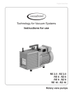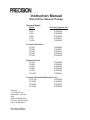
1
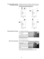
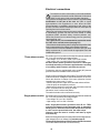
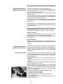
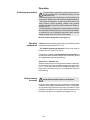
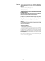
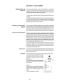
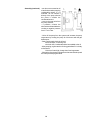
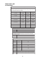
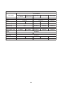
Instruction Manual
Direct Drive Vacuum Pumps
Standard Models
Model
P100
P200
P300
P420
P765
P1420
Precision Catalog No.
51220221
51220225
51220229
51220233
51220237
51220240
Corrosion Resistant
PC100
PC200
PC300
PC420
PC765
51220223
51220227
51220231
51220235
51220238
Explosion Proof
PX100
PX200
PX300
PX420
PX765
PX1420
51220222
51220226
51220230
51220234
51220239
51220241
Corrosion Resistant/Explosion Proof
PCX 100
51220224
PCX200
51220228
PCX300
51220232
PCX420
51220236
Precision
170 Marcel Drive
Winchester, VA 22602
USA
Phone: 540-869-8623
Toll Free: 800-621-8820
FAX: 540-869-8626
Manual P/N 83000027
Rev. B Dated 15NOV01
NOTICE
THE MATERIAL IN THIS MANUAL IS FOR INFORMATION PURPOSES ONLY. THE
CONTENTS AND THE PRODUCT IT DESCRIBES ARE SUBJECT TO CHANGE WITHOUT
NOTICE. PRECISION MAKES NO REPRESENTATIONS OR WARRANTIES WITH RESPECT
TO THIS MANUAL. IN NO EVENT SHALL PRECISION BE LIABLE FOR ANY DAMAGES,
DIRECT OR INCIDENTAL, ARISING OUT OF OR RELATED TO THE USE OF THIS
MANUAL.
For repair information or replacement parts assistance from the manufacturer,
call Customer Service using our toll free telephone number.
800-621-8820
(FAX) 540-869-0130
ii
REVISION STATUS
INDEX
DATE
A
6/00
B
11/01
AMENDED PAGES
NOTES
40
Add P765 and P1420 references
Add Spare parts and warranty info
Corrected P100-420 motor part no.
iii
Contents
The Precision P Series Vacuum Pumps
Introduction and Unpacking.................................................................................................. 1
Presentation of the product range ......................................................................................... 2
Operating principle of
a rotary vane pump ...............................................................................................................4
Technical characteristics ......................................................................................................7
Pump dimensions.................................................................................................................8
Installation and connections
Safety instructions ..............................................................................................................10
Filling with oil ..................................................................................................................... 12
Mechanical connections .....................................................................................................13
Electrical connections ........................................................................................................ 15
Motor protection .................................................................................................................. 16
Operation
Precautions ........................................................................................................................ 18
Operating temperature ........................................................................................................ 18
Before starting up lhe pump................................................................................................ 18
Start-up ............................................................................................................................... 19
Operation of gas ballast ...................................................................................................... 20
Particular uses ................................................................................................................... 22
Oxygen pumping ................................................................................................................23
High pressure pumping and cycling ................................................................................... 24
Maintenance
Precautions ........................................................................................................................ 25
Troubleshooting and corrective actions .............................................................................. 26
Maintenance frequency ...................................................................................................... 29
Draining the oil ................................................................................................................... 29
Flushing the pump ..............................................................................................................30
Change of type of oil........................................................................................................... 30
Replacement of front shaft seal .......................................................................................... 31
Disassembling the pump ....................................................................................................32
Cleaning components ........................................................................................................ 35
Replacement of all shaft seals............................................................................................ 36
Reassembling the pump ....................................................................................................37
Spare parts and accessories .............................................................................................. 39
Warranty ............................................................................................................................41
iv
Introduction
Unpacking and Damage
Your satisfaction and safety are important to PRECISION
and a complete understanding of this unit is necessary
to attain these objectives.
This product was carefully packed and thoroughly inspected
before leaving our factory. Save all packing material if
apparatus is received damaged.
As the ultimate user of this apparatus, you have the
responsibility to understand its proper function and
operational characteristics. This instruction manual
should be thoroughly read and all operators given adequate
training before attempting to place this unit in service.
Awareness of the stated cautions and warnings, and
compliance with recommended operating parameters
— together with maintenance requirements — are
important for safe and satisfactory operation. The unit
should be used for its intended application; alterations
or modifications will void the warranty.
Responsibility for safe delivery was assumed by the carrier
upon acceptance of the shipment; therefore, claims for
loss or damage sustained in transit must be made upon
the carrier by the recipient as follows:
Visible Loss or Damage: Note any external
evidence of loss or damage on the freight bill or express
receipt, and have it signed by the carrier's agent. Failure to
adequately describe such external evidence of loss or
damage may result in the carrier's refusing to honor your
claim. The form required to file such claim will be supplied
by the carrier.
WARNING
AS A ROUTINE LABORATORY PRECAUTION,
ALWAYS WEAR SAFETY GLASSES WHEN
WORKING WITH THIS APPARATUS.
This product is not intended, nor can it be used, as a
sterile or patient connected device. In addition, this
apparatus is not designed for use in Class I, II, or III
locations as defined by the National Electrical Code.
Concealed Loss or Damage: Concealed loss or
damage is any loss or damage which does not become
apparent until the merchandise has been unpacked and
inspected. Should either occur, make a written request for
inspection by carrier's agent within 15 days of the delivery
date; then file a claim with the carrier.
If you follow the above instructions carefully, PRECISION
will guarantee our full support of your claim to be
compensated for loss or damage in transit.
DO NOT — for any reason — return this unit to
PRECISION without first obtaining return
authorization. In any correspondence with PRECISION
please supply the nameplate data, including catalog
number and serial number.
1
Presentation of the product range
A wide range
Specific solutions adapted to various
applications
Precision oil seal rotary vane pumps are used in all vacuum
technology applications
They can be used on their own to achieve a maximum vacuum of
103 Torr (103 mbar), or in pumping assemblies, e.g. at the exhaust
of a diffusion pump or turbo-molecular pump.
Standard pumps
These pumps are used in all noncorrosive applications.
Manufacture of light bulbs, production of 1V tubes, manufacture of
electronic tubes, metallurgy, centrifuges, vacuum ovens, etc.
Corrosion resistant
Pumps suited to the pumping of corrosive gases.
R&D, laboratories, freeze-drying, pumping of solvents, extractions,
etc.
Explosion proof
Pumps with sealed motors.
For all applications in class I-II, group D, E, F and G environments.
Explosion proof / Corrosion
resistant
For use in applications in class I - II, group D, E, F and G
environments where corrosive gasses will be produced.
2
Precision P series Pumps
Features
Four 5 to 21 m3/h pump models with the
following main characteristics:
• A direct drive motor makes the pumps very
compact.
• An electrically insulated foldaway handle is
used for easy carrying.
• An anti-suck-back system ensures the
tightness of the pump during accidental or
voluntary shutdowns.
• A gas ballast enables the pumping of
condensable vapors .
• The universal three-phase or single-phase
motor can be disassembled independently of
the rest of the pump, without the need to drain
the oil case.
• On the oil case, a vertical sight glass can be
used to inspect the oil level easily when filling
the tank and during the operation of the pump.
1.
2.
3.
4.
5.
6.
Oil case
Gas ballast control
Base
Oil level sight glass
Filling plugs
Draining plug
7.
8.
9.
10.
11.
12.
Frame
Inlet end fitting
Exhaust end fitting
Foldaway handle
Electric motor
IEC electric socket
The inlet and exhaust end fittings are PNEUROP ISO-KF
standardized. They are fitted vertically on the pump at delivery but
can be positioned on the horizontal openings if required by
operating conditions.
They can also be used to connect many of our accessories.
The main replacement parts are interchangeable: This enables
easier disassembly-assembly operations and replacement without
changing the pump’s performance.
Various accessories can be used to adapt the pump to meet the
requirements of your application. These accessories can be
mounted to the top or the side inlet and exhaust ports.
The moulded aluminium pump frame supports the pumping module
and the motor. All the parts of the pumping module in contact with
gases are free of zinc, copper and cadmium.
The other construction materials include cast iron, aluminium
alloy, stainless steel, fluorocarbons (FPM), nitryl (NBR) and
chemically resistant polymers.
3
Operating principle of the rotary vane pump
Rotary Each stage of the PRECISION P series pumps consists of:
vane pump
- A hollow cylindrical stator with inlet and exhaust valves.
- A rotor mounted eccentrically inside the stator for pumping.
- Two vanes sliding in the rotor, forced against the stator by
centrifugal force and springs.
The pumping cycle is
given below:
As the vane passes in front of the inlet
orifice, an increasing space is formed
into which the gas from the chamber to
be evacuated expands. When the second
vane passes, the space is closed.
Inlet
Transfer
The gas trapped in the space between the
two vanes is transferred to the exhaust
orifice as the rotor rotates.
Compression
The space communicates with the
exhaust, which is fitted with a valve: the
gas is compressed until the safety valve
is opened.
Exhaust
The gas is expelled into the oil casing
when the pressure is sufficient to open
the valve.
Application
Single stage rotary vane pumps are the best choice for continuous
pressures above 1.0 Torr (1,3 mbar), as well as applications where
large amounts of condensable gases are present.
4
Two-stage To improve the backing pressure and flow rate at low pressure, two
rotary vane pump stages are connected in series. The second is similar to the first
both structurally and operationally. The gases pulled in by the first
(low pressure) stage are transferred to the second (high pressure)
stage and discharged through the high pressure (HP) valve.
In.
Exh.
Low pressure stage
Application
High pressure stage
Two stage rotary vane pumps are the best choice for application
requiring an ultimate vacuum as low as 10.3 Torr (1.33 x 10.3 mbar).
NOTE:
WHEN OPERATING A TWO STAGE VANE PUMP
CONTINUOUSLY, GREATER THAN HALF AN HOUR, ABOVE
10 TORR, THE UNIT SHOULD BE EQUIPPED WITH AN OIL
MIST ELIMINATOR AND OIL RETURN SYSTEM, OR A SINGLE
STAGE PUMP SHOULD BE USED.
5
Oil
Its function
Oil has several important functions in the pump:
-Itlubricatesmechanicalcomponents(bearings,seals,rotor,vanes,etc.).
- It makes moving parts relatively tight by limiting internal leakage.
-Itcarriesawaytheheatproducedbythecompressedgases.
Choosing the right oil
Not all oils produce the same ultimate pressure in a given pump.
Ultimate pressure depends on the saturated vapor pressure of the oil,
its viscosity and its ability to dissolve gases.
Good pumping conditions are related to the type of oil used.
The choice depends on:
- Expected pump performance.
- Chemical aggression and corrosion of pumped gases.
- Accessories used.
- Desired maintenance intervals and total operating cost.
PRECISION has selected various types of oil for its pumps.
Lubrication and antinoise
device
The pump is equipped with a lubrication system which regulates
the oil flow rate required in the vacuum pump. In addition this
system also ensures the gassing of the lubrication oil and therefore
the low noise level of the pump.
Gas ballast When condensable vapors are
being pumped, gas is
compressed beyond its
saturated vapor pressure in the
“compression” phase and can
condense, impairing pump
performance.
The gas ballast can be used to inject a certain quantity of air
(neutral or dry gas) into the last stage of the pump during the
“compression” phase so that the partial pressure of the pumped
gas is less than its saturated vapor pressure at the temperature
of the pump. Condensation is therefore impossible if this limit is
not reached. The maximum admissible vapor pressure is obtained
at pump inlet for this value.
At the end of “compression”, the pressure in the exhaust chamber
is greater than atmospheric pressure. An anti-suck-back device
(valve + spring) prevents the gases and oil from being drawn back
into the inlet.
The saturated vapor pressure of a body is higher when the system
is hot than when it is cold; therefore, the pump must reach
operating temperature before pumping condensable vapors.
-Using the gas ballast increases the ultimate pressure
of the pump as well as the temperature.
- The gas ballast control, located at the front of the oil
case cannot be used to set the gas injection flow rate.
- When the gas ballast control is open, the pump is not tight
when stopped. To guarantee this tightness, install an
automatic gas ballast.
6
Technical Characteristics
Standard Series:
Characteristics
Unit
Frequency
P100/PX100 P200/PX200 P300/PX300 P420/PX420 P765/PX765 P1420/PX1420
Hz
50
60
Number of Stages
50
60
2
50
60
2
50
60
2
50
2
60
50
60
2
2
Rotation speed
rpm
1500
1800
Nominal flow rate
m3/h
cfm
5.4
6.5
3.8
9.7
11.6
6.8
15
18
10.6
20.7
24.8
14.6
30
36
23.3
60
72
42.4
Flow rate Pneurop method
m3/h
cfm
4.8
5.7
3.35
8.5
10.2
6
12.5
15
8.8
15.5
20
11.8
27
31.9
18.8
55
64.6
38
Partial ultimate pressure *
with Alcatel 120 oil
Torr/mbar
/Pa
7.5x10⁻⁵ / 1x10⁻⁴
1x10⁻²
1.5x10⁻⁴/2x12.2x10-4/3x10-4
0-4
3x10⁻³
-2
2x10
Ultimate pressure
with gas ballast closed
Torr/mbar
Pa
1.5x10⁻³ / 2x10⁻³
2x10⁻¹
2.2x10⁻³/ 3x10⁻³
3x10⁻¹
Ultimate pressure with
gas ballast open
Torr/mbar
Pa
7.5x10⁻³ / 10-2
1
1.5x10⁻³/ 2x10⁻²
2
Oil Capacity
Weight (pump + motor)
Maximum water vapor pumping
capacity (Ballast flowrate 1.1 m 3 / h)
l
0.83
0.95
0.95
0.98
3.6
7.0
kg(lbs)
25 (55)**
26 (57.2)**
27 (59.4)**
28 (61.6)**
61 (134)
93 (205)
7
700
30
3000
25
2500
700
1200
mbar
Pa
Water vapor pumping capacity
Inlet and exhaust end fittings
1500 1800 1500 1800 1500 1800 1500 1800 1500 1800
35
25
20
15
12
10
3500 2500 2000 1500 1200 1000
g/h
120
110
125
ISO-KF
100
110
100
90
90
DN 25
DN 40
* Partial pressure measured according to Pneurop 6602 specificatin. It may vary if other oils are used.
** These values are for pumps equipped with universal single phase motors.
Note: The pressure measurements were made with a capacitive diaphragm pressure gauge measuring a total
pressure in the absence of a cold trap. Measurements using a Pirani type gauge can give different pressure values.
Corrosive applications:
Characteristics
Frequency
Unit
Hz
PC100
PCX100
PC200
PCX200
PC300
PCX300
PC420
PCX420
50
50
50
50
60
Number of Stages
60
2
60
2
60
2
PC765
50
60
2
2
Rotation speed
rpm
1500
1800
Nominal flow rate
m3/h
cfm
5.4
6.5
3.8
9.7
11.6
6.8
15
18
10.6
20.7
24.8
14.6
30
36
23.3
Flow rate Pneurop method
m3/h
cfm
4.8
5.7
3.35
8.5
10.2
6
12.5
15
8.8
15.5
20
11.8
27
31.9
18.8
Partial ultimate pressure *
with Alcatel 120 oil
Torr/mbar
/Pa
7.5x10⁻⁵ / 1x10⁻⁴
1x10⁻²
1.5x10⁻⁴/2x10-4
2x10⁻²
Ultimate pressure
with gas ballast closed
Torr/mbar
Pa
1.5x10⁻³ / 2x10⁻³
2x10⁻¹
2.2x10⁻³/ 3x10⁻³
3x10⁻¹
Ultimate pressure with
gas ballast open
Torr/mbar
Pa
7.5x10⁻³ / 10-2
1
1.5x10⁻³/ 2x10⁻²
2
Oil Capacity
1500 1800 1500 1800 1500 1800 1500 1800
l
0.83
0.95
0.95
0.98
3.6
Weight (pump + motor)
kg(lbs)
25 (55)**
26 (57.2)**
27 (59.4)**
28 (61.6)**
61 (134)
Maximum water vapor pumping
capacity (Ballast flowrate 1.1 m 3 / h)
mbar
Pa
7
700
30
3000
Water vapor pumping capacity
Inlet and exhaust end fittings
g/h
35
25
20
15
12
10
3500 2500 2000 1500 1200 1000
120
110
ISO-KF
125
100
110
100
90
90
DN 25
* Partial pressure measured according to Pneurop 6602 specificatin. It may vary if other oils are used.
** These values are for pumps equipped with universal single phase motors.
7
700
DN 40
Pump Dimensions
Pump Styles P100 - P420
Dim.
Pump Type
(mm)
P 100
P 200
P 300
P 420
A
228
245
270
291
B
143
200
225
246
8
Pump Styles P-765 and P-1420
Dimensional drawings
P-765 / PX765 - P-1420 / PX1420
b
D
336/ 385
H
exhaust
a
Gas ballast
362 to 385
410 to 422
288/ 342
Fill plug
11/4 G
323/371
Inlet
103
118
53 42
56 45
NW 40
L
164/ 186
455/ 529
31/ 29
12
12
Drain plug 3/8 G
206/ 229
140/ 190
375/ 459
437/ 521
213/ 264
Types 33/63
PC-765
Fill plug
11/4 G
Inert gas inlet
1/8 NPT
Oil casing purge
1/8 NPT
D
Ø 76
H
Exhaust
NW 40
b
Oil filter
53 42
56 45
Gas ballast
389 to 398
438 to 447
Inlet
a
323/ 371
L
103
118
164/ 186
452/ 526
288/ 342
336/ 385
91
91
31/ 29
12
12
Drain plug 3/8 G
206/ 229
375/ 459
437/ 521
140/ 190
213/264
Types 33/63
Dimensions
Dimensions
P/N
Motor
type
L
mm
D
mm
H
mm
a
mm
b
mm
P-765
PC-765
UL/CSA
CE
240
185
142
265
87
P/N
Motor
type
P-1420 UL/CSA
PC-1420
CE
9
L
mm
D
mm
H
mm
a
mm
b
mm
285
195
149
25
87
Safety instructions concerning the installation and
operation of pumping systems
Before switching on the equipment, the user must read
all of the start-up and operation sections of this manual
and observe the safety instructions listed in the booklet
of declarations of compliance supplied with the unit.
Unpacking When you receive the equipment, unpack it carefully. Do not
discard the packaging until you have ensured that the pump has
not been damaged during transport. Otherwise, take the necessary
measures with the transporting company and, if necessary, notify
PRECISION.
For all handling, only use the devices provided for this purpose
(lifting rings, handle, etc.).
The pump is not supplied filled with oil. The oil is contained
in separate bottles. Similarly, it is recommended to drain the
pump before re-dispatching the equipment.
Storage
• If the pump is to be stored, we guarantee the reliability of our
equipment without particular storage precautions for up to 3 months
(ambient temperature between 41°F and 149°F or 5 and 65°C).
• For storage periods of over 3 months, we recommend to fill the pump
with oil during storage. For this, fill the pump and run it at ultimate
vacuum (inlet orifice blocked) for approximately 1 hour in order to
lubricate all the parts of the functional block (see page 18).
Then, stop the pump and store it with the inlet and exhaust orifices
sealed: clamping ring, centering ring, plug, etc.
The shaft should be rotated by starting the pump every six months
following this storage procedure.
• After 6 months storage without oil, factors such as temperature,
degree of humidity, salt air, etc. may cause the deterioration of the
pump components, particularly the hardening of O-rings and the
“sticking” of lip seals on shafts and the gumming of oil In this state,
a pump may have operation problems, particularly oil leaks Before
the next start-up, the pump must be disassembled (see page 31),
and all the seals changed.
Note 1:
The seal kits must be stored with caution. Keep them away from
heat and light (sunlight and ultraviolet light) in order to prevent the
elastomers from hardening (AFNOR standard FD T 46.022).
10
Installation and • The machines must be connected to an electrical installation in
start-up compliance with decree 88-1056 dated 14th November 1988, as
well as any local electrical codes that apply.
• It is important to isolate the machine from the power source before
any maintenance is done on the equipment.
• When switching off the power of equipment containing capacitors
loaded with over 60 VDC or 25 VAC, take precautions when
accessing the connector pins (single phase motors, equipment
with mains filter, frequency converter, monitor, etc.).
• Vane roughing pumps use lubricants. It is recommended to
request information from the manufacturer on the safety data
sheets concerning the product used.
• Our pumps are tested in the factory with a high quality distilled
oil. PRECISION recommends the use of PRECISION B+ oil with
all of their vacuum pumps. If changing the type of oil, refer to the
chapter concerned for the procedure and the type of lubricant
required.
• Our pumps are designed to prevent any thermal risk for user
safety. However, specific operating conditions may generate
temperatures which may justify particular attention on the part of
the user (outer surfaces > 70°C).
11
Filling with oil
PRECISION two-stage pumps for corrosive applications are tested
in the factory with a high quality distilled oil.
At delivery, there is some oil remaining in the functional block.
Our pumps are tested in the factory with a high quality
distilled oil. PRECISION recommends the use of PRECISION
B+ oil with all of their vacuum pumps. To change the type
of oil, refer to the Maintenance Chapter, “replacement of type of oil”
section. In all cases, follow the recommendations of the
pump specifier for the choice of oil to be used.
If necessary, carry out the
special preparation procedure
for the pump, then, remove the
filling cap and fill with oil until
the oil reaches the highest
mark on the sight glass.
This operation must be
performed with the pump
switched off. The second filling
orifice is used if an external oil
filtration device is connected.
Checking the oil level To use the pump in optimum conditions, the oil level must be
observed and checked regularly. This level is checked with the
pump switched off, hot and on a horizontal plane.
Oil level sight glass for
PC Series Pumps
Oil level sight glass for
P Series Pumps
Note: Optimum pump performance and service life are obtained
when the oil level is between the maximum level and the minimum
level.
12
Mechanical connections
For a given application, pump performance, vacuum
characteristics, temperature and reliability depend on the
following:
- assembly conditions, accessory filters.
- the oil used.
- mechanical connections: pipes, etc.
- maintenance frequency and quality.
For the assembly of the vacuum circuit, provide the accessories
required for maintenance: valves, purges, etc.
Mounting on a frame
The pump can be mounted on a frame using the 4 attachment holes
on the base and the shock mounts supplied.
Note: Special shock mounts, effective against the pump’s own
vibrations, can also be used but they do not ensure correct
attachment during the transfer of equipment. In this case, the pump
should be clamped onto its support.
Ventilation The pump and the motor are each equipped with a ventilation
system. During pump installation, the pump should be placed in
ventilated place. Provide a minimum gap of 25 mm around the
pump.
The vents on the pump and the motor should be checked
regularly to ensure that they are not blocked.
PRECISION P series pumps are designed for operation at an
ambient temperature between 53°F and 113°F (1 2 and 45°C).
Inlet and exhaust fitting
Remove the protective caps on the inlet and exhaust
orifices; these components prevent foreign bodies from
entering the pump during transport and storage. It is
dangerous to leave them on the pump during operation.
The pump inlet and exhaust orifices are equipped with DN 25 ISOKF end fittings which can be used to fit various line components
made of stainless steel, plastic, etc..
Exhaust
Inlet
Make sure that all the
It is recommended to
components or the
connect the pump exhaust
chamber connected to
to a smoke / mist
the pump inlet withstand a eliminator.
negative pressure of 1 bar relative • If the pump exhaust orifice is
to atmospheric pressure.
connected to an extraction duct
or an oil mist eliminator, the
exhaust stop valve fitted in the
pump exhaust orifice must be
removed.
• At the pump exhaust, the
evacuation circuit must be such
that the resulting excess pressure
Also make sure that in the oil case is as low as
the maximum excess possible: for correct pump
pressure does not exceed operation the max. exhaust
1 bar relative to atmospheric pressure recommended should
be 1.125 Tor (1.5 bar) absolute
pressure (for security).
pressure.
13
Changing position of inlet Depending on the types of accessories used and the pumping
and exhaust fittings conditions, these orifices can be fitted vertically on the pump or
horizontally as shown on the diagram below.
Note: The pump is supplied in configuration A.
Disassembling the fittings
Unfasten the attachment
screw from the end fitting
to be removed.
4
30 Unfasten the end fitting
and remove it from its
housing along with the O-ring In
the case of the inlet end fitting,
also remove the inlet filter.
Horizontal reassembly
Remove the attachment screw
from the lateral cap and
using a wide screwdriver,
remove the cap.
• Position the end fitting in the
corresponding lateral orifice
taking care to fit the O-ring.
Attach the end fitting with the
screw.
In the case of the inlet end
fitting, fit the filter at the bottom of the orifice.
• Close unused orifices with plugs and fasten the screws.
14
Electrical connections
The machines must be connected to an electrical installation
in compliance with the decree 88-056 dated 14 November
1988, as well as any local electrical codes that apply.
• Our products are designed to meet current EEC regulations. Any
modification on the part of the user are liable to cause
noncompliance with regulations or even affect the EMC
(Electromagnetic compatibility) performance and safety of the
product. Precision cannot be held responsible for consequences
resulting from such an intervention.
• Before any maintenance intervention on a product performed by
a maintenance operator who has not been trained on safety
regulations (EMC. electrical safety, chemical pollution, etc.)
isolate the product from its various energy sources (electricity,
compressed air, etc.).
• As a general rule, it is recommended to protect the motor
for 120% of its nominal current (see page 15).
• Check that the electrical wiring and the voltage selector position of the
motor correspond to the line voltage, before starting up the pump.
• Ensure that the electrical installation conforms with your local
safety requirements. It must include the appropriate fuse and
reliable earth ground.
Three-phase version Electrical motor is in accordance with major international standards
(UL, CSA, CE) and offers two voltage ranges:
• Low voltage: 170 V to 254 V 50Hz 170 V to 300 V 60Hz,
• High voltage: 342 V to 460V 50Hz-342V to 520V 60Hz.
All three phase motors (protection level IP 43. TEFC type)
must be protected by a customer supplied starter consisting
of a suitably rated contactor and thermal overload.
Furthermore, they are equipped with a dry contact (NC) thermal
protection which is available in the terminal box.
Wire the motor according to the line voltage. The connections to be
made are shown on a diagram inside the terminal box or on its lid.
Check the direction of rotation of the motor (direction of arrow
located on the motor cover). For this:
• Remove the protective caps on the inlet and exhaust orifices.
• Vent the pump to atmospheric pressure.
• Switch on the pump for 2 to 3 seconds, with your hand on the inlet
orifice. If suction is felt, the wiring is correct.
Otherwise, invert 2 consecutive phases.
The earth terminal must be connected correctly.
Single-phase version Electrical motor is in accordance with major international standards
(UL, CSA, CE) and offers two voltage ranges:
• Low voltage: 90 V to 132 V 50/60Hz.
• High voltage: 180 V to 254 V 50/60Hz.
Note: single-phase motors (protection level IP 43 - TEFC
type) have a thermal circuit interrupter with an automatic
starting device: when the internal motor temperature reaches
a value over the preset limit value, the motor stops.
However, when the motor is cooled, it will start up again
automatically.
Before connecting to the mains, check the position of the voltage selector:
High Voltage (HV) or Low Voltage (LV) (see table page 16)
The plug is equipped with a ground pin which must be connected.
The motor rotation direction is set at the factory.
15
External motor protection, electrical protection
Motor characteristics, The information below is given as a recommendation.
The user must comply with the electrical standards or
connection, protection recommendations (IEC, VDE, UL, CSA, etc.) applicable in the
country in which the pump is used.
The use of electrical protection for the pump motor makes it
possible to protect:
• The motor: in the event of excess voltage or rotor blocking, the
resulting excess current may destroy the coil and possibly the
start-up system (for a single-phase motor).
• The pump: in the event of a lubrication fault (contaminated oil,
presence of particles), increased resistance will draw excessive
motor current.
Differential thermal circuit-breakers should be used, in which the
mechanism contains an instantaneous disconnection controlled
by a bimetal blade.
Never protect a three-phase motor with fuses not equipped
with a differential system: if three phase motors are powered on
2 phases without a differential system, the motor could burn.
single-phase motor:
The table on the following page gives the characteristics at startup (for temperatures ≥ 12°C) and in permanent operation.
In this table, you will find, for each pump, a standard fuse or motorassociated value.
three-phase motor:
The table on the following page gives, for each pump, the electrical
characteristics in permanent operation and the proposed circuit
breaker.
Single-phase motors Single-phase motors have a thermal circuit switch with automatic
Specific internal protection
starting device (CSA standard): when the internal motor temperature
reaches a value over the preset limit value, the motor stops.
However, when the motor is cooled, it will start-up again
automatically.
Voltage range change
The voltage range can be read beside the motor switch: the dual
frequency single-phase motor can be configured for low voltage
(LV) or high voltage (HV). To change this type of connection,
proceed as follows:
• make sure that the motor is not switched on, and the power cord
is removed,
• unfasten the 4 attachment screws on the motor upper cover and
remove it,
• remove the voltage selector cover marked with the voltage, press
on the voltage selector (position II).
• invert the position of the voltage selector cover in order to show
the other voltage at the outside of the motor cover: ‘HV’ for high
voltages, or “LV’ for low voltages. Check to be sure that the voltage
selector has fully latched the rocket switch when the voltage
selector cover is replaced.
• install the upper cover and refasten the 4 screws.
• secure the upper cover as follows:
• Center it on the front motor flange,
• Install the connector between the relay and condenser,
• Close the upper cover,
• Install and tighten the 4 screws, starting installing the screws on
the pump handle side first.
16
Three-phase motors
Electrical connections
The pumps are equipped with 9 wire terminal box motors, the wiring
diagram of the terminals is given as a rough guide only. In the event
of doubt, only the plate in the terminal box should be used as a
reference.
Terminal box (9 wires)
Summary tables of various The characteristics and ratings of fuses and circuit breaker
of motors standard PRECISION pump
types of motors associated with types
3
motors, 5 to 21 m /h, single-phase or three-phase.
Single-phase motor
Current at
Ultimate Pressure (A)
Voltage/Frequency
*Start-up
current (A)
Proposed
Fuse protection (A)
50 Hz
60 Hz
50 Hz
60 Hz
100V 50/60 Hz
115V 60 Hz
5.0
3.5
4.0
30.0
34.0
35.0
20/20
20
8/6
6
200V 50/60 Hz
2.5
2.0
14.0
19.0
10/16
4/4
20.0
16
4
10
4
2.0
220V 60 Hz
230V 50 Hz
3.5
8.0
Standard Type aM**
* Temperature = 12°C
** aM: Motor-associated type fuse
Three-phase motor
*Start-up
current (A)
Voltage/Frequency
Proposed Circuit
Breaker protection (A)
50 Hz
60 Hz
Standard Type aM**
200V 50/60 Hz
3.1
2.8
4
3.5
220V 50/60 Hz
240V 50 Hz
3.5
4.0
3.1
4.5
5
4
Low voltage
3.7
280V 60 Hz
4.5
High votlage
380V 50 Hz
1.5
2
415V 50 Hz
1.6
2
480V 60 Hz
1.6
* Temperature = 12°C
17
2
Operation
Preliminary precautions
• The performance and operating safely of this product can
only be guaranteed if it is operated according to normal
conditions of use.
• The vacuum pump is also a compressor: incorrect operation may
be dangerous. Study the user manual before starting up the pump.
• The pumps are designed to prevent any thermal risk for user
safely. However, specific operating conditions may generate
temperatures which may justify particular attention on the part of
the user > 70°C).
• Product tightness is guaranteed for normal operating conditions
when the product leaves the factory. It is the user’s responsibility
to maintain the level of tightness particularly when pumping
dangerous products (on PC or PCX series pumps).
Be sure to fill the pump with oil (see page 11)
Operating • At start-up, before switching on the motor, check that the oil bath
temperature temperature is greater than 53°F (12°C).
• The ambient operating temperature for the pump must be
between 53°F (12°C) and 113°F (45°C).
• Under these conditions, the stabilized pump temperature (at
the front of the oil case) will be between 140°F and 158°F (60 and
70°C) (depending on operating conditions).
Special case - Synthetic oils
Synthetic oils are much more viscous when cold than mineral oils.
Do not start up the pump at ambient temperatures below 59°F
(15°C). For the same reason and to facilitate lubrication of the
pump, pour a few drops of oil (I to 2 cm3) through the inlet orifice
before starting.
Before starting
the pump
Check that the exhaust orifice is not blocked.
In certain cases, when the pump is ,started up in cold ambient
conditions, or with slightly contaminated oil, the current after startup may remain high until the oil in the pump is heated up. These
conditions are sufficient for the internal thermal protection to be
activated, making start-up impossible (see pages 15 & 16).
18
Start-up • When using a three phase motor, check the direction of
rotation of the motor (see electrical connections start-up chap.
page 14)
• Check the oil level (See page 11).
• Start-up the pump.
• Allow the pump to run for one hour with the inlet blocked
at ultimate vacuum:
During this operation, make sure that the oil circuit is operating.
Remove one of the oil fill plugs to listen to the pump.
At start-up, the oil enters the lubrication circuit of the vacuum
pump. As a result, noises will be heard (first irregularly, then
regularly) which will reduce as the oil heats up. These noises will
no longer be heard when the fill plug has been replaced.
Under normal temperature conditions, the oil circuit should start
less than
1 minute after start-up (this time may vary with the type of oil and
its degree of contamination).
• Using the gas ballast:
- to decontaminate the pump’s oil;
- to accelerate heating. It is normal for the oil level to change (as
can be seen through the oil sight glass) when the pump is hot, due
to expansion of the oil, starting of the oil circuit and the operating
conditions of the pump (inlet pressure). If necessary, stop the
pump and adjust the oil level between the “max” and “min” levels
on the sight glass.
In the event of a malfunction, refer to the “Troubleshooting and
corrective actions” table (page 25).
19
Operation of gas ballast
Regeneration of In a pump stored with the same oil for a long time, condensed
pump oil vapors may contaminate the oil bath and affect performance. This
is also the case after pumping vapors and when the oil appears
cloudy or discolored through the sight glass.
• Run the pump, shutting it off from the system at the inlet by a valve
or a plug.
• Open the gas ballast and allow the pump to operate for 1/2 hour
to 1 hour, or longer if the oil remains cloudy. This operation
accelerates the temperature rise of the pump while eliminating
residual vapors present in the oil bath.
Pumping condensable
vapors
To pump with condensable products, it is necessary to operate
with a hot pump. For this, isolate the pump from the system and
allow it to operate for 1/2 hour with the gas ballast open, or 1 hour
(if possible) with the gas ballast closed. When the oil bath is hot,
the condensation of vapors in the pump is reduced or prevented.
Choice of pump and system
The pump’s capacity to eliminate condensable vapors is related to
their type, the pump temperature and the quantity of air introduced
by the gas ballast. Thus, for high vapor levels in a system, the singlestage pump is more suitable. However, when not pumping vapors, its
ultimate pressure is higher. Care should be taken to limit the inlet
pressure of the pump to its maximum admissible water vapor
pressure with the pumped product. This is obtained by reading the
pump characteristic table for water vapor.
The use of cold traps or condensers are recommended when large
quantities of vapors are to be extracted. Excessively intense or
prolonged pumping may cause the products condensed in the trap
to be evaporated a second time.
Choice of oil
Choose an oil which facilitates the separation of pumped products
which may be condensed in the oil bath (anti-emulsion oil for waterbased compounds, etc.)
Assembly
The condensation of vapors at the pump exhaust is reduced if:
• the pump and oil temperature are high;
• the pressure at the exhaust is as low as
possible (removal of the oil mist
eliminator...);
• the condensates are collected separately
from the oil bath and do not block the
exhaust duct.
For this:
• avoid using any vertical ducting which
promotes the condensation of products
and the return of these products to the
pump.
• use a condensate collector;
20
Assembly (continued)
• we do not recommend an oil
mist eliminator when pumping
condensable vapors: if it is
essential, do not connect it
directly to the pump exhaust
but place it outside the
condensation zone.
• remove the stop valve from
the pump exhaust;
• if possible, connect the
exhaust to a mechanical device
creating a negative pressure
from 0.1 to 0.2 bar.
- Valve off the pump from the system and increase the pump
temperature by running the pump for 30 minutes with the gas
ballast open.
- Start pumping and check the oil level:
• the level drops, oil is being lost;
• the level rises, condensates have been added to the oil.
- After pumping, regenerate the oil using gas ballast if it is cloudy
or discolored.
• if the level is too high, change the oil and regenerate.
- Change the oil as soon as inlet pressure characteristics drop and
are not improved by regeneration.
21
Purges for pumping condensable,
corrosive, and hazardous gases
All pump models
Purges
The use of vane pumps may result in pumping gases or vapors
which are flammable or that could contaminate the oil. In this case,
these products must be diluted using purges supplied with dry
gases, such as nitrogen to avoid undesirable reactions.
For this purpose, a filtered dry nitrogen supply or other inert gas
with the same characteristics is required:
- condensation point < 22°C,
- dust < 1µm,
- minimum absolute pressure 2 bar.
Oil case purges
The purge dilutes pumped gases with a neutral gas:
it makes it possible to limit corrosion in the oil case, condensation
and accumulation of gases in dead spaces of the pump.
Connect the nitrogen supply to one of the unused filling plugs on
the oil case (BSPP 1/8 Gas connection).
Set the nitrogen pressure to approximately 1.2 PSIG (0.1 relative
bar) (flow 50 to 300 SCCM) and the flow rate so as to satisfy the
dilution conditions.
Caution: do not generate an excess pressure > 14 PSIG (1 relative
bar).
Use of purge with gas ballast
A neutral gas supply can also be connected via the gas ballast
(BSPP 1/8 Gas connection).
22
Oxygen pumping
In certain applications, mixtures containing oxygen at different
concentrations, or even pure oxygen, are used.
Oils of mineral origin are combustible. Exposure to pure oxygen at
high temperatures may cause them to self-ignite. In addition, they
are highly oxidized during pumping and quickly lose their lubricating
properties. Mineral oils must not be used for oxygen levels of over
21% in pumped gases In this case, perflourinated synthetic oils
must be used.
The use of these oils requires a special pump preparation (see
page 29).
The pump must be completely disassembled and all traces oil
mineral oil removed. Flushing the oil case is not adequate.
In addition, it is strongly recommended not to use fluids such
as tri-aryl-phosphate-ester which are known to cause
accidents.
Any accumulation of oxygen in the installation should be avoided
and the oxygen or combustible mixture should be diluted with a
neutral gas at the exhaust: the gas flow rate should be 4 times the
oxygen flow rate.
Certain combustible or explosive gases require a higher
degree of dilution. Our International Support Services and
Customer Services can advise you to help solve problems
of this kind.
23
Recovery of oil (high pressure and cycling)
When the pump operates at high pressure, the oil heats up,
becomes more fluid and is flushed out of the functional block by the
gas stream.
Oil losses at the exhaust are increased.
For intermittent If the pump only operates for a very short time at high pressure,
pumping the lubricating oil is replaced when the pump returns to low
pressure. The use of a oil mist eliminator prevents losses due to
intermittent high pressure operation.
For cyclical pumping If the pump operates at high pressure in a cyclical fashion, oil
consumption may reach sufficiently high levels (according to the
pumped volume and pumping cycle rates) causing the level to drop
in the oil case.
There is then a risk of seizure due to a lack of oil. In addition, the
high flow of gas passing through the eliminator prevents oil from
returning to the oil case.
In order to pump in these conditions, the pump must be equipped
with an oil recirculating kit, which enables oil recovery via the gas
ballast.
Cyclical pumping:
ODK type oil recovery device
Drain kit, type I
Device is not tight
when switched off.
Drain kit, type II
An electro-valve ensures
tightness when switched off.
For continuous pumping at In this case, or when very large volumes (requiring several hours of
high pressure pumping) are being pumped, it is recommended to recover the oil
via the pump inlet.
24
Maintenance
General precautions For normal operations, the maintenance of PRECISION P series
pumps only require regular oil changes.
Before any draining or maintenance operation, check the
pumping conditions of the installation: potential toxicity,
corrosion or radioactivity of pumped gases.
Depending on the case, we recommend:
• to purge the pumping installation with dry nitrogen before
maintenance;
• wear gloves, protective goggles and, if necessary, a breathing
apparatus;
• ventilate the premises well and disassemble the equipment
under a suction hood;
• not to dispose of used oils and residues using the standard
system and, if necessary, have them destroyed by a
specialized company.
After a complete maintenance operation, it is recommended
to perform a helium leak tightness test.
25
Troubleshooting and corrective actions
Incidents
The pump is not running
Causes
Corrective actions
• Incorrect motor power supply.
• Temperature too low.
• Gumming of seals after prolonged
storage.
Check the power supply.
Reheat the pump and its oil.
1 - Disassemble the motor and try to
turn the fan manually.
2 - Disassemble, clean the pump,
replace seals, reassemble.
Drain, flush and refill with clean oil.
Replace by disassembling the motor.
Disassemble, clean, hone the
scratched metal parts (replace them
if necessary) and reassemble.
• Oil contaminated after pumping.
• Motor coupling damaged.
• Pump seized, due to a stopping
after pumping in difficult conditions
(no draining or flushing).
The pump does not start
• Oil cold.
• Insufficient oil in the oil case.
• Oil contaminated.
• Oil pump inlet partially blocked.
• Lubrication holes blocked.
• Vane or spinner-cam (SD models)
damaged.
• Incorrect anti-suck-back system
assembly.
The vacuum pump does not
produce a vacuum
Warm pump.
Fill up to the level.
Drain, flush and refill with clean oil.
Drain, and clean the oil pump inlet
duct.
Disassemble and clean.
Replace them.
Repeat the assembly and the setting.
Ultimate pressure obtained: a few mbar, Torr
• Direction of motor rotation
incorrect (three phase).
• Insufficient motor power.
• Inlet filter blocked.
• Insufficient oil in the oil case.
• Oil cold, oil pump inlet blocked.
• Oil contaminated.
• Oil pump inlet partially blocked.
• One of the LP safety valves is
damaged:
• Part forgotten in reassembly.
26
Rewire.
Check the power supply.
Clean it.
Add oil.
Warm, disassemble, clean.
Drain, flush and start again with
clean oil.
Drain and clean the oil pump inlet
duct.
Replace.
Repeat the reassembly.
Incidents
The vacuum pump does not
produce a vacuum (continued)
Noisy pump
Pump too hot
Causes
Corrective actions
Ultimate pressure obtained: a few 10.2 Torr (10.2 mbar)
• Gas ballast adjustment button
open.
• O-ring pinched.
• One of the seals is damaged.
• One of the HP safety valves is
damaged.
• Lubrication holes blocked.
• Incorrect anti-suck-back assembly.
• Part forgotten in reassembly.
Accessories
• At the pump exhaust, the
installation produces an exhaust
pressure of 1.125 Torr (1.5 bar).
• Oil mist eliminator cartridge
clogged.
• Oil level too high.
• Oil contaminated (presence of
particles).
• Pump not prepared for the oil
used.
• Incorrect motor power supply.
• Motor bearings damaged.
• Motor coupling incorrectly set or
damaged.
• Incorrect fan assembly.
• Incorrect anti suck-back device
assembly
• Vanes damaged or stuck.
• Ambient temperature too high.
• Pump placed in a poorly ventilated
place or vents blocked.
• Operation at high pressure
P > 22 Torr (30 mbar).
• Excess pressure at exhaust.
• Motor in overvoltage or
Motor in short-circuit.
• Oil contaminated.
• Pump not prepared for the oil
used or oil unsuitable.
27
Close.
Replace.
Replace.
Replace.
Disassemble and clean.
Repeat the assembly and setting.
Repeat the reassembly.
Check the installation.
Replace.
Drain and fill with a new oil.
Drain, flush and refill with clean oil.
Check the pump configuration or the
type of oil.
Check the power supply.
Replace the motor after inspection.
Check the setting.
Check the assembly.
Repeat the assembly.
Replace.
Check the installation.
Check for system leaks.
Check the exhaust line.
Check the voltage, replace the
motor.
Drain, flush and refill with clean oil.
Check pump configuration or type
of oil.
Incidents
Causes
Corrective actions
• Oil level too high.
• Operation at high pressure.
Drain and fill with new oil.
Use an oil recirculating kit.
• Gas ballast open:
1 - accidentally,
2 - pumping of condensable
vapors.
• Leak at oil case seal or at front
seal.
1 - Close.
2 - Use a condensate collector.
Poor pump tightness when
switched off
•
•
•
•
•
•
Close.
Replace.
Repeat the assembly.
Replace.
Replace.
Drain, flush and refill with clean oil.
Oil in base
• Oil case and frame cleaned poorly
during reassembly.
• Oil case seal pinched
Considerable oil losses
Gas ballast open
Safety valve damaged
Incorrect anti-suck-back assembly.
O-ring pinched
Seals damaged.
Oil contaminated.
• Front seal damaged or felt
saturated.
28
Check the assembly and replace
the seals if necessary.
Remove the base and clean.
Disassemble the oil case, clean
the faces and refit a new seal
Replace
Maintenance
Maintenance frequency An incorrect ultimate vacuum or a reduction in pumping
speed are signs that the oil has deteriorated.
The periodic inspection of the state of the oil is performed by
comparison with a sample of new oil in order to check the level of
contamination or deterioration of the lubricant.
The frequency at which oil is renewed is adapted to the type of
operation:
• if the oil is cloudy, this indicates that condensables have been
absorbed during pumping. The oil can be regenerated using the gas
ballast (see page 19 ).
• a thickening of the oil, together with a blackish color and a “burnt”
smell indicate that the oil has deteriorated.
Drain the pump and flush it.
Normally, for a pump operating continuously at a pressure
lower than 0.75 Torr (1 mbar) with a clean gas (dry air), the
oil should be changed every 6 months. This value is given as
a guide only. It may be extended to 1 year if the ultimate vacuum
required is sufficient (for primary vacuum pumps).
Similarly, if the pump is stopped frequently for long periods,
the oil should be changed at intervals of 6 months to a
maximum of 1 year (oil may become sticky).
Note: Every pumping operation is different. This oil must therefore
be changed at intervals adapted to each specific application. The
use of certain accessories can reduce the frequency of these
maintenance operations.
Draining
The draining operation places the contaminated
pumping circuit in communication with the outside
atmosphere. Take all necessary steps to ensure
personal safety.
The pump must be drained when hot and after the oil case has been
vented to atmospheric pressure. For this:
• switch off the pump;
• isolate the pump or disconnect
from the installation;
• tilt the pump;
• unscrew the draining plug on
the side of the oil case and the
filling plug on the top of the oil
case.
When all the oil has drained,
replace the two plugs
temporarily and run the pump
for about 10 seconds leaving the
intake open. Take care with the
oil mist which may appear at the
exhaust. This operation removes the oil from the functional block;
• drain this oil by removing the draining plug;
• replace the draining plug and fill with fresh oil to the appropriate
maximum level of the oil case oil sight glass through the filling
orifice. (see page 11).
29
Flushing
The draining operation can be followed by a flushing operation if the
oil is particularly dirty. This operation requires a volume of oil equal
to the capacity of the pump.
After draining the oil case (see page 28), replace the draining plug.
Remove the intake filter, clean it and replace it. Run the pump at
atmospheric pressure, pour the flushing oil very slowly through the
inlet orifice. Take care with oil mist which may develop at the
exhaust. Stop the pump and drain the flushing oil via the draining
plug. Replace the plug and fill with fresh oil (see page11).
Change type of oil PRECISION P Series pumps are tested in the factory with a high
quality distilled oil, unless specified otherwise in the order. When
the pump is delivered, a certain quantity of oil remains in the
functional block.
Thus, if you wish to use another type of oil, proceed as follows:
Compatible oils Mineral oil can be replaced by another type of mineral oil. Simply
flush the pump (see above) using the new oil and fill the pump (see
page 11). Mineral oils are also compatible with mineral-based
synthetic oils
This is the case when, for example, a mineral oil is replaced by a
synthetic oil. Synthetic oils are considered to be incompatible with
each other tor practical reasons: they are expensive. A mixture
may cause slight cloudiness of the resulting mixture, which could
be interpreted mistakenly as a sign of contamination or deterioration.
For the same reasons, clear synthetic and mineral oils, which are
also expensive, are treated as synthetic oils
These remarks apply to ester or fluorocarbon type synthetic oils.
Proceed as follows:
- Disassemble the pump completely and clean it (see page 31).
- Reassemble it.
- Connect an oil mist eliminator to the pump exhaust.
- Fill the pump with the new oil (see page 11).
NOTE: to replace a synthetic oil by a mineral oil, proceed as for
compatible oils.
30
Replacement of front seal
In the event of an external oil leak
on the pump, it is necessary to
change the shaft seal on the motor
side.
You will need:
• a front seal replacement kit, if
available, or a minor maintenance
repair kit.
• a screwdriver,
• a 3, 4 and 5 mm Allen wrench.
• Stop the pump and disconnect
the power cord motor.
• Disconnect the pump from the installation to which it is connected
• If possible, position the pump vertically, with the motor at the top,
resting on the front side of the oil case; in this position, it is not
necessary to drain the oil case. Otherwise, disassemble the pump
in the horizontal position, resting it on its base, after it has been
drained.
• Disconnect the motor by unscrewing the 4 fastening screws,
simultaneously and alternately.
• Remove the motor vertically.
• Unscrew the fan fastening screw. Remove the fan, the key and
the support washer.
• With a screwdriver, remove the shaft sleeve and its O-ring.
• Unscrew the two seat-holder fastening screws and remove the
seal-holder.
• Remove the seal from the seal-holder as described on page 35
and discard it.
• Clean the metal parts. Inspect the wearing side of the shaft
sleeve: after cleaning, the sleeve may show a perfectly normal
trace of rubbing (caused by polishing). Should the sleeve show any
signs of indentation or grooves, it must be replaced.
• Preferably use new parts from the seal kit or set of seals.
• Reassemble the lip seal in its housing as described on page 35.
• Reinsert the new O-ring on the seal-holder.
• Insert the shaft sleeve inside the seal-holder.
• Engage the reassembled seal-holder on its axis and screw onto
the frame.
• Insert the O-ring in the shaft sleeve. Position the support washer.
Then, install the key, reassemble the fan and the motor in the
reverse order of disassembly.
• Immediately order a replacement maintenance set or kit.
31
Disassembling the pump
Disassembling the motor
block
Disassembling the fan
3
5
Remove the motor cover.
Remove the motor
attachment screws.
4
Remove the fan fastening
screw and the support washer.
Remove the key.
Replacing the front seal
Disassembling the gas
ballast (1)
Disassembling the oil
sight glass (2)
Removing the oil case (3)
See page 30.
2.5
Remove the gas ballast
cover (2 screws), the
adjustment button, the spring
and the sleeve. Remove the
tank feed-through (2 screws)
and its seal.
3
Remove the sight glass
cover. Remove the plate, the
sight glass and the O-ring.
5
Remove the oil case and
its O-ring after removing the 4
fastening screws
32
Disassembling the exhaust
valve cover
Disassembling the
P Series Pumps
oil system
5
Remove the cover(s), the
exhaust valves and their
springs.
The oil system is set in the
factory, it must be reset in
the event of disassembly
(see reassembly). However,
the rear flange (7) can be
disassembled
without
modifying the setting.
Remove the spinner cam (8)
by removing the circlip.
Do not disassemble the nozzle
to clean it. During the
reassembly, check that it is
not blocked by sending a jet of
compressed air through it.
Disassembling the
5 Remove the cover from
P Series Pumps
oil system the oil pump (9). Release the
cylinder (15) equipped with the
washer, piston and spring.
Release the stop valve (10)
from its housing.
12 Unscrew the seat of the
stop valve (11) and remove the
O-ring.
Then remove the vane (12), the
oil pump rotor (13) and the
Oldham coupling (14).
33
Disassembling the exhaust
valve cover
Disassembling the
HP stator and the rotor
(two-stage pumps)
10 Remove the 4 nuts (and washers). Release the flange in the
axis.
Remove the stator by sliding it
along the rotor.
Release the rotor and the
vanes.
Disassembling the Insert two screwdrivers in the
intermediate flange notches and release the flange
in the axis.
(two-stage pumps)
Disassembling the Remove the LP stator.
LP stator and the rotor Remove the rotor and the vanes
equipped with the springs.
34
Cleaning components
Cleaning metal components Solvents are required to clean components.
Standard precautions should be taken in compliance with the
manufacturer’s instructions.
After use in mineral or synthetic oil, clean the metal components
with a mineral products based solvent such as AXAREL(1) ,
CARECLEAN(2), PREMACLEAN(3), NAPHTEOL(4).
Proceed as follows:
• Clean when cold or hot (max. 45°C) by dipping or using a cloth
• Vacuum dry in a ventilated oven
• The component must be cleaned a second time with alcohol.
After use in (perfluorinate) synthetic oil, clean the metal
components in a solvent such as GALDEN S 90™ (5) and proceed
as follows:
• Clean when cold by dipping or using a cloth
• Dry the components in the air or with compressed air
After use in (non-perfluorinate) synthetic or mineral oil,
clean the metal components with a solvent such as alcohol and
proceed as follows:
• Clean when cold by dipping or using a cloth
• Dry the components in the air
• Industrial washing solutions can also be used. The cleaning
operation should be followed by vacuum drying.
Cleaning the oil level sight glass
P series pumps
PC series pumps
When cleaning this plastic sight glass, avoid contact with alcohol
or alcohol-based washing solutions. Clean the component with a
solvent, but do not steep it, and rinse it immediately.
The sight glass of these pumps is made of glass.
(1)
(2)
(3)
(4)
(5)
DUPONT DE NEMOURS registered trademark
CASTROL registered trademark
DOW registered trademark
Nippon Chemical registered trademark
MONTEDISON registered trademark
35
Replacement of shaft seals
Specific tools
Recommended tools
• Specific assembly mandrel.
• A support plate (or washer).
• A flat screwdriver
Extracting a shaft seal from With the flange flat, the seal
its housing is extracted using a
screwdriver, resting on the
plate (or washer) so as not to
damage the seal housing.
Assembling the shaft seal
The seal housing and the seal
lip are lubricated with the
lubricant used in the pump.
The flange is resting on a flat
surface.
According to the direction
of assembly specific to each
pump, the seal is fitted on the
assembly mandrel.
Ø 24.5
± 0.1
5.5 ± 0.2
+0.2
Ø 14 0
+0.2
10
à 45˚C
Mandrel
Using a press or a hammer,
the seal is inserted in its
housing.
Direction of assembly They are fitted using the assembly mandrel according to the
of shaft seals direction of assembly below:
HP stator
LP stator
LP rotor
HP rotor
rear flange
36
median flange
frame
seal holder
Reassembling the pump
Component preparation • Rest the frame on a flat surface in order to raise the pump.
• All surfaces in contact are coated with oil.
• Observe a nominal clamping torque of 0.8 mdaN (5.8 ftlbs)
for the reassembly of the functional block.
The functional block is reassembled in the reverse order of
disassembly.
Reassembling the On the median flange, check that the lubrication
median flange hole is not blocked.
New vanes are assembled on the rotors, with the
rounded edges facing outwards.
Reassembling the Pour a small quantity of oil beforehand around the exhaust valve
exhaust valve cover holes. Position exhaust valve cover the exhaust valves, the springs
and the exhaust valve covers.
Setting the oil system P series pumps
Offset the spinner-cam (1) by pressing on the blades.
Turn the shaft up to the
maximum displacement of
the lever (2).
The distance between the
seat (3) and the stop valve (4)
must be 0.9 to 1.2mm (0.035
to 0.047 inch):
it is set by adjusting the
orientation of the lever.
2
4
1
3
0,9 to 1,2 mm
The stop valve face must be perpendicular to the axis of the oil inlet
hole; when free, the stop valve should rest on its seat: check the
parallelism of the lever in relation to the bearing face of the stop
valve seat. Orient the seat to obtain the correct setting.
PC series pump
Position the rotor of the oil pump so that the slot is horizontal (or
parallel with the pump base). To turn it, use the fan. Do not forget
the Oldham coupling.
37
Reassembling the oil case Fit the oil case on the frame. Fasten the attachments after making
sure that the seal is positioned in its seal groove (clamping torque
0.8 mdaN (5.8 ft lbs)).
Reassembling the gas ballast Position the oil case feed-through equipped with the seal in its
housing by centering it on the gas ballast tube. Assemble using the
screws.
Equip the adjustment knob with the sleeve and the spring. Position
the assembly in the cover and secure on the oil case feed-through.
Replace the O-ring (included in the seal kit).
Reassembling the oil Fit the sight glass and assemble with screws (clamping torque 0.3
level sight glass mdaN (2.14 ft lbs)).
PC series pump: The sight glass is made of glass:
gradually tighten the two attachment screws in
alternation to avoid placing the sight glass under
stress.
See page 30.
Reassembling the Fit the fan 1/2 sleeve.
seal holder
Fit the drive key on the motor shaft.
Reassembling the Install the motor coupling sleeve down to the stop on the motor
motor side components shaft.
Fit the motor on the frame and install the 4 mounting bolts
(clamping torque 1 mdaN (7.14 ft lbs)).
38
SPARE PARTS AND
ACCESSORIES
Maintenance and Repair Kits
MINOR KIT includes gaskets, shaft and valve seals, and O-rings .
MAJOR KIT includes the contents of MINOR KIT plus vanes, spring, gas ballast valves, drain
valve, sight glass and flexible motor coupling.
Pump Type
Minor
Major
Shaft Seal Kit
P / PX-100
51245305
51245383
34102605
PC / PCX-100
51245306
51245315
81000951
P / PX-200
51245305
51245320
34102605
PC / PCX-200
51245306
51245327
81000951
P / PX-300
51245305
51245337
34102605
PC / PCX-300
51245306
51245338
81000951
P / PX-420
51245305
51245339
34102605
PC / PCX-420
51245306
51245340
81000951
P/PX-765
51245415
51245418
use minor kit
PC-765
51245312
51245313
use minor kit
P/PX-1420
51245421
51245388
use minor kit
PC-1420
51245417
51245419
use minor kit
PUMP ACCESSORIES
Catalog No.
Description
34001241
Smoke/Mist Eliminator
VACUUM OIL
Precision B+
Premium Grade, double distilled, high purity, low vapor pressure oil for both direct
drive and belt drive pumps.
36069125
Quart, 6/case
34002655
Gallon, 4/case
34002656
5-gallon container
VACUUM TUBING, RED GUM RUBBER
Part No.
Inner Diameter
Wall Thickness
34166732
1/4"
3/8"
34166873
3/8"
3/8"
34167006
1/2"
3/8"
34167068
3/4"
3/8"
34167095
1"
3/8"
34167100
1-1/4"
1/2"
34167105
1-1/2"
1/2"
34257012
Adjustable tubing clamp for 34167068, 34167095, and 34167100
34257053
Adjustable tubing clamp for 34166783, 34166732 and 34167006
51200817
Vacuum Gauge Assembly
39
Miscellaneous Spare Parts
Part numbers
Description
P/PX100 P / P X 420
PC/PCX 100 PC/PCX 420
P/PX 765
P C / P C X 765
P/PX 1420
Base plate
81000942
81000972
81000973
Motor
81000844
81000970
81000971
NW 25 o-ring
81000940
81000941
N/A
N/A
N/A
NW 25 clamp
81000949
N/A
N/A
N/A
NW 40 o-ring
N/A
81000974
81000975
81000974
NW 40 clamp
N/A
Oil sight glass cover
81000922
81000976
81000923
Handle
Fill plug
Packing carton
81000923
81000922
81000943
81000944
81000977
Drain plug
Gas ballast knob
81000922
81000944
81000945
81000946
81000947
81000980
81000981
81000978
40
81000980
81000979
Warranty
PRECISION warrants its products against defects in material or in workmanship, when used under appropriate
conditions and in accordance with appropriate operating instructions for a period of no less than one (1) year from
the date of delivery of the products.
Sole obligation of PRECISION shall be to repair or replace at our option, FOB factory or locally, without charge, any
part(s) that prove defective within the warranty period, provided the customer notifies PRECISION promptly and in
writing of any such defect. Compensation for labor by other than PRECISION employees will not be our obligation.
Part(s) replacement does not constitute an extension of the original warranty period.
PRECISION MAKES NO WARRANTY OF MERCHANTABILITY, FITNESS FOR A PARTICULAR PURPOSE, OR
ANY OTHER WARRANTY, EXPRESSED OR IMPLIED, AS TO THE DESIGN, SALE, INSTALLATION, OR USE OF
ITS PRODUCTS, AND SHALL NOT BE LIABLE FOR CONSEQUENTIAL DAMAGES RESULTING FROM THE
USE OF ITS PRODUCTS.
PRECISION will not assume responsibility for unauthorized repairs or failure as a result of unauthorized product
modifications, or for repairs, replacements, or modifications negligently or otherwise improperly made or performed
by persons other than PRECISION employees or authorized representatives.
While our personnel are available to advise customers concerning general applications of all manufactured products,
oral representations are not warranties with respect to particular applications and should not be relied upon if
inconsistent with product specifications or the terms stated herein.
In any event, the terms and conditions contained in PRECISION formal sales contracts shall be controlling; and any
changes must be in writing and signed by an authorized executive of PRECISION.
All defective components will be replaced without charge one (1) year from the date of delivery. There will be no charge
for labor if the apparatus is returned to the factory prepaid.
Conditions and qualifications of the warranty statement shall prevail at all times.
41