1
SECURITY SYSTEM
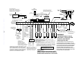
4110XM
EW
ANT N
T
R
O
R IMP
O
ION!
F
T
R
A
E
M
V
E CO
NFOR
I
D
I
D
S
N
N
SEE I
RES A
U
T
A
FE
Installation Instructions • Installation Instructions • Installation Instructions
N5478V5 7/96
WWW.DIYALARMFORUM.COM
Please Read
INFORMATION CONCERNING NEW FEATURES
Controls with microprocessor part number N7185V3 or higher contain the following new features. These controls
can be identified via the downloader as Rev. 06.
1.
This control complies with National Fire Protection Association (NFPA) requirements for temporal pulse sounding of fire notification
appliances. Fire alarms now sound as interrupted pulses consisting of three pulses and a brief pause (i.e. ring, ring, ring, pause ring, ring, ring, pause, etc.)
2.
Capability has been added for the control to call a pager on the secondary telephone number. This can only be used if the primary
reporting format is Ademco Contact ID. The following entries have been added to program field *49 (Split/Dual Reporting) for the
purpose of paging messages:
Primary
Secondary (Paging number)
6 = All reports except Open/Close
7 = All reports
8 = All reports
Alarms/ Open/Close, Troubles
Alarms, Troubles
Alarms, Open/Close, Troubles
Touch-tone codes sent to the pager are:
1911 = Alarm
1001 = Open
1002 = Close
1811 = Trouble
No restore reports are sent to the pager.
3.
Three additional user codes have been added (identified as Users 5, 6, and 7).
4.
Duress is now User 8 (no longer User code + 1).
5.
AC Loss report is now sent at a random time delay up to 1 hour. If AC is restored before the report goes out, no report will be sent.
6.
Telephone number entries can now contain *, #, and a 2-second pause.
Enter # + 11 for "*"
Enter # + 12 for "#"
Enter # + 13 for 2-sec. pause
7.
Audible Exit Warning option has been added (field *27: 0 = no; 1 = yes [default = 1]). If enabled, beeping will occur during exit time
and will change from slow to rapid beeping during last 5 seconds of exit delay.
8.
Master code is now able to change itself in normal operating mode. To change, enter:
[Master code] + [8] + [1] + [new Master code] + [new Master code] again.
9.
New Telco Hand-off feature allows the technician at the site to call the downloading facility from the control panel phone line,
initiate a site download (Master Code + # +1), and the control will immediately be on-line with the modem at the downloading
facility.
10.
If all power is lost at the control, upon power up, the armed status will be the same as it was before the power loss. Bypasses,
however, are not retained.
11.
The control checks for the physical battery connection every two minutes. If connection is lost, a visual and audible trouble is
indicated, and a communicator report will be sent (if programmed). The actual condition of the battery is still checked once every
four hours. To clear the low battery message after the low battery condition is restored, enter Test mode: [User code] + [5];
otherwise it will clear itself the next time the system checks the battery's condition.
–2–
WWW.DIYALARMFORUM.COM
TABLE OF CONTENTS
.
RECOMMENDATIONS FOR PROPER PROTECTION ................. 3
Section 1. GENERAL DESCRIPTION ............................................................................... 4
FEATURES .................................................................................................... 4
SPECIFICATIONS ........................................................................................ 4
COMPATIBLE DEVICES .............................................................................. 5
ZONE RESPONSE TYPE CHARACTERISTICS ......................................... 5
Section 2. SYSTEM INSTALLATION AND WIRING ...................................................... 6
INSTALLING THE SYSTEM ........................................................................ 6
Install the Control Cabinet .................................................................... 6
Install Remote Keypads .......................................................................... 7
Install Hardwired Zones ......................................................................... 7
Install the 4281 RF Receiver .................................................................. 7
Install Sounding Devices ........................................................................ 7
Install the Remote Keyswitch ................................................................ 8
Connect Telephone Line ......................................................................... 8
Connect AC Transformer ........................................................................ 8
Connect the Battery ................................................................................ 8
Connect Earth Ground ............................................................................ 8
Install Wireless Transmitters ................................................................ 9
WIRING GUIDELINES ................................................................................. 9
Section 3. PROGRAMMING THE SYSTEM ..................................................................... 10
The Mechanics of Programming ............................................................. 10
Entering Program Mode ......................................................................... 10
Programming a Data Field ..................................................................... 10
Reviewing a Data Field .......................................................................... 10
Erasing an Entry in a Data Field .......................................................... 10
Downloading ............................................................................................ 10
Clearing All Data Fields ......................................................................... 10
Exiting the Programming Mode ............................................................. 10
Section 4. SYSTEM OPERATION ...................................................................................... 11
USER ACCESS CODES ................................................................................ 11
Adding a Secondary User Code .............................................................. 11
Deleting a Secondary User Code ............................................................ 11
KEYPAD FUNCTIONS ................................................................................. 11
System Commands .................................................................................. 11
Panic Keys ............................................................................................... 12
Keyswitch Operation .............................................................................. 12
Keyswitch LED Indications .................................................................... 12
Section 5. TESTING THE SYSTEM ..................................................................................... 13
Armed System Test ................................................................................. 13
Transmitter ID Sniffer Mode .................................................................. 13
Go/No Go Test Mode ............................................................................... 14
House ID Sniffer Mode ............................................................................ 14
Section 6. TROUBLESHOOTING GUIDE ........................................................................ 15
REGULATORY AGENCY STATEMENTS ...................................................... 16
THE LIMITATIONS OF THIS ALARM SYSTEM ......................................... 17
DIP SWITCH TABLES FOR WIRELESS DEVICES .................................... 18
SUMMARY OF CONNECTIONS DIAGRAM ................................................. 19
ADEMCO Limited Warranty ............................................................ Back Cover
–3–
WWW.DIYALARMFORUM.COM
RECOMMENDATIONS FOR PROPER PROTECTION
The Following Recommendations For The Location Of Fire And
Burglary Detection Devices Help Provide Proper Coverage For
The Protected Premises.
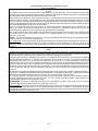
Recommendations For Smoke And Heat Detectors
With regard to the number and placement of smoke/heat detectors, we subscribe to the
recommendations contained in the National Fire Protection Association's (NFPA) Standard #72
noted below.
Early warning fire detection is best achieved by the installation of fire detection equipment
in all rooms and areas of the household as follows: For minimum protection a smoke detector
should be installed outside of each separate sleeping area, and on each additional floor of a
multi-floor family living unit, including basements. The installation of smoke detectors in
kitchens, attics (finished or unfinished), or in garages is not normally recommended.
For additional protection the NFPA recommends that you install heat or smoke detectors in
the living room, dining room, bedroom(s), kitchen, hallway(s), attic, furnace room, utility and
storage rooms, basements and attached garages.
In addition, we recommend the following:
• Install a smoke detector inside every bedroom where a smoker sleeps.
• Install a smoke detector inside every bedroom where someone sleeps with the door partly
or completely closed. Smoke could be blocked by the closed door. Also, an alarm in the
hallway outside may not wake up the sleeper if the door is closed.
• Install a smoke detector inside bedrooms where electrical appliances (such as portable
heaters, air conditioners or humidifiers) are used.
• Install a smoke detector at both ends of a hallway if the hallway is more than 40 feet (12
meters) long.
• Install smoke detectors in any room where an alarm control is located, or in any room
where alarm control connections to an AC source or phone lines are made. If detectors are
not so located, a fire within the room could prevent the control from reporting a fire or an
intrusion.
✪
KITCHEN
▲
DINING
✪
✪
✪
BEDROOM BEDROOM
TV ROOM
■
✪
✪
LIVING ROOM
BEDROOM
▲
KITCHEN
✪
DINING
■
LIVING ROOM
✪
■
✪
BDRM
BDRM
✪
BEDROOM
✪
▲
■ Smoke Detectors for Minimum Protection
✪ Smoke Detectors for Additional Protection
▲ Heat-Activated Detectors
■
BEDROOM
✪
■
✪
BEDROOM
TO
BR
BEDROOM
■
▲
▲
KTCHN
.
LVNG RM
■
CLOSED
DOOR
GARAGE
BASEMENT
Recommendations For Proper Intrusion Protection
For proper intrusion coverage, sensors should be located at every possible point of entry to a home or
commercial premises. This would include any skylights that may be present, and the upper windows
in a multi-level building.
In addition, we recommend that radio backup be used in a security system so that alarm signals can
still be sent to the alarm monitoring station in the event that the telephone lines are out of order
(alarm signals are normally sent over the phone lines, if connected to an alarm monitoring station).
–5–
WWW.DIYALARMFORUM.COM
Section 1. GENERAL DESCRIPTION
The 4110XM is a microprocessor-based state-of-the-art security control intended for wired and wireless
applications. The Control Panel supports up to 14 zones, using basic hard-wired, and/or wireless.
––––––––––––––––––––––––––––––––– FEATURES –––––––––––––––––––––––––––––––––
Zones Supported
•
•
6 hardwire zones,
characteristics:
Security Codes
having
the
following
•
1 master code for entire system (user 1)
•
6 secondary user codes (users 2-7)
◊
EOLR supervision supporting N.O. or N.C.
sensors.
•
Duress code assigned as user 8
◊
300-500 msec normal response.
Keypad Panic Keys
◊
Zone 3 programmable for Fast Response to
open (10mS).
•
Provides programmable panic key functions
•
Activated by wired & wireless keypads
Alarm Output
Up to 8 wireless zones:
◊
Requires the use of a 4281 (5700 System) type
RF receiver as indicated below.
Receiver Model
No. of Zones
4281L
4281M
4281H
up to 4
up to 8
up to 8
•
Provides a 12VDC, 2 AMP output (assumes a fully
charged 4AH battery is connected)
•
Steady output for Burglary/Panic, or pulsing
output for Fire
•
Output is current limited
Communication Formats
•
◊
Requires the use of 5700 series wireless
transmitters.
•
◊
Detects signals within a nominal range of 200
feet.
•
Ademco Low Speed (Standard or Expanded):
1400Hz ACK/KISSOFF.
Sescoa/Radionics (Standard or Expanded):
2300Hz ACK/KISSOFF.
Ademco Express :
DTMF, 1400/2300Hz ACK, 1400Hz KISSOFF.
•
Ademco Contact ID:
DTMF 1400/2300Hz ACK, 1400Hz KISSOFF.
––––––––––––––––––––––––––––– SPECIFICATIONS –––––––––––––––––––––––––––––––
4110XM SECURITY CONTROL
1.
Physical: ........................................12-1/2" W x 14-1/2" H x 3" D (318mm x 368mm x 76mm)
2.
Electrical:
Voltage Input: ................................
16.5VAC from plug-in 25VA transformer, Ademco No. 1321/TF2 (in U.S.A.),
1321CN (in Canada)
Rechargeable Back-Up Battery: ... 12VDC, 4AH (Gel type).
Charging Voltage: ..........................13.8VDC.
Alarm Sounder: ............................. 12V, 2.0 Amp output
Auxiliary Power Output: ............... 12VDC, 500mA max. Interrupts for 4-wire smoke detector reset.
Maximum Zone Resistance: ..... Zones 1-6 = 300 ohms excluding EOLR
Fuse: ................................................battery (3A) No. 90-12
Line Seize:
3.
....................................Double Pole
Regulatory Information
Ringer Equivalence: ..................... 0.7B
FCC Registration No.: ................... AC 398U-68192-AL-E
UL File No. ....................................S1632, Guide UXOU
UL
In UL installations, maximum current draw from the Auxiliary Output and the Alarm Output
combined must not exceed 600mA total.
-5WWW.DIYALARMFORUM.COM
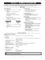
–––––––––––––––––––––––––– COMPATIBLE DEVICES –––––––––––––––––––––––––––
Remote Keypads (up to 4)
5700 Series Transmitters
Model
4127, 6127
Type
Fixed English
4137AD, 6137, 6128
Fixed English Addressable
5330 (Select for Vista)
Alpha
IMPORTANT
Addressable keypads must be used in
the non-addressable mode (Device
Address 31), which is pre-set at the
factory. Do not set these keypads to
any other addresses.
Smoke Detectors (4-wire only)
Model
Type
1412
Ionization Products of Combustion
Detector
Photoelectric Smoke Detector
Photoelectric Smoke Detector)w/135º F
(57º C) Heat Detector)
2412
2412TH
Fire Supervisory Module
Model
5701
5706
5707
5711
Description
Panic Transmitter
Photoelectric Smoke
Detectors
Slimline Door/
Window Transmitter
5715WH Universal Transmitter
5716
Door/Window
5716WM Transmitter
5742
Audio Discriminator
5743
Dual Technology
Glassbreak Detector
5775
PIR Detector
5727
Wireless Keypad
5827BD Wireless Bi-directional
Keypad
5799
Magnets
UL
Zone Num.
62 or 63
48-55
1-63
1-63
1-63
1-63
1-63
32-47
House ID
House ID
The 5711, 5715, and 5716 do not supervise
their loop wiring. Therefore, their loop
wiring may not exceed three feet.
Optional Keyswitch
A77-71601 EOL Relay Module (supervises power
for 4-wire fire zone).
4116 Keyswitch
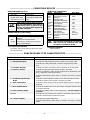
––––––––––––––––– ZONE RESPONSE TYPE CHARACTERISTICS –––––––––––––––––
Zone Response Type
Characteristics
0 – Zone Disabled
1 – Entry/Exit Burglary
• Provides exit delay time when panel is armed in any arming mode.
• Provides entry delay when panel is armed in Away and Stay modes
only.
3 – Perimeter Burglary
• Provides an instant alarm when panel is armed in any arming mode.
4 – Interior, Follower
• Provides exit delay time when panel is armed in any mode.
• Will only provide entry delay if an Entry/Exit zone is faulted first upon
entry. Otherwise, alarm will be instant.
• Bypassed automatically when panel is armed in the Stay or Instant
mode.
5 – Trouble by Day/Alarm by
Night
• Provides a trouble response if panel is not armed when zone is faulted.
6 – 24-Hr. Silent Alarm
• Provides a silent alarm to Central Station whether panel is armed or
disarmed.
7 – 24 Hr. Audible Alarm
• Provides an audible alarm at the bell output and keypad whether panel
is armed or disarmed.
8 – 24-Hr. Auxiliary Alarm
• Provides an audible alarm at the keypad only.
provided.
9 – Fire
• Provides a fire alarm when zone is shorted. Causes bell output to pulse.
• Provides an instant alarm if panel is armed in any mode.
No bell output is
• Provides a trouble response when zone is open.
10 – Interior w/Delay
• Provides entry and exit delay times.
• Bypassed automatically when panel is armed in the Stay or Instant
mode.
-6WWW.DIYALARMFORUM.COM
Section 2.
SYSTEM INSTALLATION AND WIRING
–––––––––––––––––––––––––
INSTALLING THE SYSTEM –––––––––––––––––
Refer to the Summary of Connections diagram on the inside back cover of this manual for terminal
connections when following these procedures.
1.
Install the Control Cabinet
• Mount the cabinet.
• Install the cabinet lock as follows:
RETAINER CLIP
(NOTE POSITION)
LOCKED
RETAINER
CLIP
RETAINER
SLOTS
UNLOCKED
CABINET DOOR BOTTOM
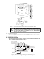
Figure 1. Installing The Cabinet Lock
• Mount the PC board either alone, or with the wireless receiver in the same cabinet (see
Figures 2 and 3 to follow).
DETAIL SIDE
VIEW OF BOARD
INSERTED INTO
SLOTS
A
B
3RD CLIP
REQUIRED
DETAIL SIDE VIEW OF CLIP AND
BOARD INSTALLED
DETAIL SIDE VIEW OF CLIP INSTALLATION
A-CABINET TAB WITHOUT CLIP
B-CABINET TAB WITH HANGING CLIP
Figure 2. Mounting The PC Board Alone
-7WWW.DIYALARMFORUM.COM
Figure 3. Mounting The PC Board And RF Receiver Together In The Cabinet
WARNING
BE SURE TO USE THE PLASTIC MOUNTING CLIPS (SUPPLIED) TO
ISOLATE THE CIRCUIT BOARDS FROM THE CABINET. FAILURE
TO DO SO MAY RESULT IN DAMAGE TO THE TRANSFORMER
AND/OR THE CIRCUIT BOARDS.
2.
Install Remote Keypads
• Determine wire gauge by referring to the wiring length/gauge chart at the end of this section.
3.
Install Hardwired Zones
4.
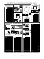
Install the 4281 RF Receiver
• With the antennas in the upright position , make sure all DIP switches are pushed to the right
(OFF – this equals address 0), as shown in Figure 4.
ANTENNAS
INSERT IN
RIGHT-HAND
TERMINALS
@@@@@@@@e?
@@@@@@@@e?
@@@@@@@@e?
@@@@@@@@e?@@@@@@@@
@@@@@@@@
@@h?
@@
@@h?
@@
@@h?
@@
@@h?
@@
@@h?
@@
@@h?
@@
@@
@@
@@
@@
@@
@@
@@
@@
@@
@@
@@
@@
@@
@@
@@
@@
@@
@@
@@
@@
@@
@@
@@
@@
CIRCUIT
BOARD
?@@
?@@
?@@
?@@
?@@
?@@
?@@@@@@@@
?@@@@@@@@
5882
LOCATION
DIP SWITCH
PLUG
&
SOCKET
}
WIRING
OPENING
KNOCKOUT
AREA FOR
SURFACE
WIRING
TO CONTROL’S REMOTE
KEYPAD CONNECTION
POINTS. EACH RECEIVER
MUST BE ON INDIVIDUAL
HOME RUN.
ON
{
INTERFERENCE
INDICATOR
LED
@@
@@
@@
@@
@@
@@
@@
@@
?@@@@@@@@
?@@@@@@@@
OFF
▲
MOUNTING
HOLES
@@g
@@g
@@g
@@g
@@g
@@g
@@@@@@@@
@@@@@@@@
YELLOW
RED
BLACK
GREEN
▲
NOTE: WHEN CIRCUIT BOARD IS
MOUNTED IN CONTROL’S CABINET,
GROUNDING LUGS (2) PROVIDED
MUST BE INSERTED IN LEFT-HANDTERMINALS OF ANTENNA BLOCKS AND
SECURED TO CABINET (SEE RECEIVER’S AND CONTROLS INSTRUCTIONS)
4
3
2
1
TO RELEASE CIRCUIT
BOARD, REMOVE
SCREWS (2) AND BEND
BACK TABS (S)
Figure 4: 4281 Wireless Receiver Showing DIP Switch Setting of "0."
-8-
WWW.DIYALARMFORUM.COM
• Use the House ID Sniffer mode to select a House ID that is not being used in a nearby system
as follows:
a. Enter the [Master Code] + [#] +[2].
While in this mode, the keypad will display the House ID transmitted by any wireless
devices in the area. It may take some time for all wireless devices in the area to send a
signal, so it is recommended that you leave the system in this mode for approximately 2
hours. If any House ID numbers are displayed, select another number for this system.
Remove all batteries from transmitters before going into the House ID
Sniffer Mode.
IMPORTANT
b. Exit this mode by entering the [Master Code] + [1] OFF.
5.
Install Sounding Devices
UL
6.
Use only UL Listed sounding devices for UL installations.
Install the Remote Keyswitch
When using a keyswitch, the system cannot support wireless.
IMPORTANT
7.
Connect the Telephone Line
Make sure telephones on the premises are connected only through the
alarm control panel (disconnect from the incoming phone line at the
telephone jack). This is necessary to have true line seizure.
IMPORTANT
8.
Connect the AC Transformer
• Use the wiring table at the end of this section for maximum wire lengths per gauge.
DO NOT PLUG THE TRANSFORMER INTO THE AC OUTLET UNTIL
ALL OTHER WIRING TO THE CONTROL IS COMPLETE.
WARNING
9.
Connect the Battery
IMPORTANT
UL
10.
Do not attach the connector cable to the battery's terminals until
after you have plugged the AC transformer into an uninterrupted
120VAC outlet.
1.
In UL installations, maximum current draw from the Auxiliary
Output and the Alarm Output combined must not exceed 600mA.
2.
Use a 3A battery or larger for UL installations.
Connect Earth Ground
• Connect Terminal 21 to a good earth ground (Metal Cold Water Pipe, or AC Power Outlet
Ground from a 3 prong, 120VAC outlet. This is necessary for the lightning protection
devices in this control to work properly.
-9WWW.DIYALARMFORUM.COM
11.
Install Wireless Transmitters
• Select a House ID (all transmitters must be set to the same House ID as you will program
into the system). To determine a House ID that is not being used in a nearby system, use
the House ID Sniffer Mode ( see Section 5: TESTING THE SYSTEM for further
instructions on using House ID Sniffer Mode).
• Determine what zone response type each transmitter will represent.
• Select each transmitter's zone number according to its zone response type (use the chart
below).
ZONE NUMBER (RF XMTR ID)
10-13
14-29
30-43
44, 45
46, 47
ZONE TYPE
ENTRY/EXIT, Burg.
PERIMETER, Burg.
INT/FOLLOWER, Burg.
INT w/DELAY, Burg.
PERIMETER, Burg.
RF XMTR ID
ZONE TYPE
48-55
56-61
FIRE
TROUBLE BY DAY/
ALARM BY NITE, Burg.
24 hr. (audible)
Programmed by field *92
62
63
• Set DIP switches on transmitters (according to each transmitter's instructions) for the zone
numbers and House ID selected (see DIP Switch Settings for Wireless Devices on page 17 of
this manual. Do not set two transmitters for the same zone number.
• Mark each transmitter's zone number so you can identify it easily when mounting.
• Program House ID and transmitter zone numbers into the system (see program fields *24
and *76 thru *92).
Do not permanently mount transmitters until transmission from each location has been
verified (see Section 5: TESTING THE SYSTEM for instructions on performing the Go/No Go
Test Mode.
––––––––––––––––––––––– WIRING GUIDELINES –––––––––––––––––
Aux Power Wire Run Chart
TOTAL CURRENT DRAWN BY ALL DEVICES* CONNECTED TO A SINGLE
WIRE RUN
Wire Size
50 mA or less
51 - 100 mA
101- 300 mA
301 - 500 mA
#22
500 ft (152m)
250 ft (76m)
80 ft (24m)
50 ft (15m)
#20
750 ft (228.6m)
380 ft (116m)
130 ft (39.6m)
80 ft (24m)
#18
1300 ft (396m)
650 ft (198m)
220 ft (67m)
130 ft (39.6m)
#16
1500 ft (457m)
1000 ft (305m)
330 ft (100.5m)
200 ft (70m)
* Includes Keypads, RF Receiver, and alarm devices requiring separate power.
Example: If you have two motion detectors that draw a total of 44 mA, and you are
using #20 AWG wire, the distance from the control panel Aux + and terminals to the last device can be up to 750 ft.
IMPORTANT
The combined length of all wire runs for devices connected to the
keypad data lines must not exceed 1500 feet (457m) when unshielded
quad conductor cable is used (750 feet if shielded cable is used). This
restriction is due to the capacitive effect on the data lines when quad
cable is used.
Transformer Wiring Table
Distance of Transformer
From the Control Panel
Up to 50 feet
50–100 feet
100–250 feet
Wire Gauge
To Use
# 20
# 18
# 16
-10WWW.DIYALARMFORUM.COM
Section 3. PROGRAMMING THE SYSTEM
For actual program fields, a programming form is included at the center of this manual.
Entering Program Mode
Use one of the following methods:
• Press both the [*] and [#] keys at the same time within 50 seconds after power is applied to the Control.
or
• After power-up, enter the [Master Code] + 8 + 0 (default Master Code is 4110)
This method is disabled if you exit the program mode using *98 instead of *99. See "Exiting Program
Mode" later in this section.
Following entry into program mode, data field *20 will be displayed (this is the first field in the system).
The system will now accept entries for field *20.
Programming a Data Field
↓ Field Number
20
Press [*] plus [Field No.] (e.g., *20), and then make the required entry. Note the following:
• The keypad beeps three times when the data field has been completely programmed
• The next Field No. is displayed. If you do not want to program this field, press [*] + the Field No. you
want to program.
• If the number of digits that you need to enter in a data field is less than the maximum digits available
(e.g., the phone number field), enter the desired data, then press [*] + the next Field No. to be
programmed.
• If you try to enter a non-existent field, the keypad will display EE or Entry Error. Simply re-enter [*]
plus a valid Field No.
Reviewing a Data Field
Press [#] plus [Field No. ]. Note the following:
•
Data will be displayed for that field number, entry by entry (a beep will be heard between entries and
three beeps after the last).
•
No changes will be accepted in this mode.
•
If you try to enter a non-existent field, the keypad will display EE or Entry Error. Simply re-enter [#]
plus a valid field number.
Erasing an Entry in a Data Field
Applies only to fields *40-*43, and *94.
Press [*] plus Field No. plus [*].
Downloading
*96 resets the Subscriber Account number and CSID in preparation for an initial download. If *97 was
entered previously, *96 must be entered last. The control can either be initiated from the control panel
(site) by entering [Master Code] + # + 1, or from the downloading computer (station).
A new Telco hand-off feature allows a technician or user at the site to call the downloading facility from the
control panel phone line and initiate a site download. By entering the Master Code + [#] + [1] while on the
line, the control will immediately be on-line with the modem at the downloading facility, where the operator
can begin downloading.
Clearing All Data Fields
*97 clears (zeros) all data fields. The Master Code will now be 0 0 0 0.
DO NOT PRESS *97 IF ANY PROGRAMMING HAS BEEN DONE
PREVIOUSLY; DATA ALREADY PROGRAMMED INTO THE SYSTEM WILL
BE DELETED.
WARNING
Exiting the Programming Mode
*98 inhibits re-entry into the programming mode with the use of the Master Code.
*99 allows re-entry into the program mode using Master Code + 8 + 0.
-11WWW.DIYALARMFORUM.COM
Section 4: SYSTEM OPERATION
––––––––––––––––––––––––––– USER ACCESS CODES ––––––––––––––––––––––––––––
Adding a Secondary User Code
MASTER CODE + [CODE KEY] + USER # ( 2-7) + DESIRED 4-DIGIT ACCESS CODE.
(The system will emit a single beep when a secondary code has been successfully entered.)
Changing the Master Code
MASTER CODE + [CODE KEY] + [1] + NEW MASTER CODE + NEW MASTER CODE AGAIN
Deleting a Secondary User Code
MASTER CODE + [CODE KEY] + USER # (2-7)
Notes:
• All Master and Secondary security codes permit access to the system for arming, disarming, etc.
• If a secondary code is inadvertently repeated for different users, the lower user number will take
priority.
• Opening and closing reports are sent for the Master as user number 1. User codes are sent as numbers
2-7, respectively.
–––––––––––––––––––––––– KEYPAD FUNCTIONS ––––––––––––––––––––––––––
System Commands
Before arming, the system must be in the READY condition (all zones must be intact). If the "NOT
READY" message appears, press the
READY [* ] key to display faulted zones.
SUMMARY OF SYSTEM COMMANDS
MODE
HOW TO PERFORM
AWAY
STAY
INSTANT
MAXIMUM
DISARM
BYPASS
QUICK BYPASS
(if enabled)
CHIME MODE
SITE-INITIATED
DOWNLOAD*
Security Code + [2]
Security Code + [3]
Security Code + [7]
Security Code + [4]
Security Code + [1]
Security Code + [6] +
Zone #(s)
Security Code + [6]
EXIT DELAY
ENTRY DELAY
Yes
Yes
Yes
Yes
Yes
Yes
No
No
PERIMETER
ARMED
Yes
Yes
Yes
Yes
INTERIOR ARMED
Yes
No
No
Yes
Security Code + [9]
(toggles on and off)
Master Code + [#] + [1]
* Initiates phone call to the downloading facility.
Panic Keys
A panic function is activated when:
• Both keys of the appropriate key pair are pressed at the same time, or
• The appropriate lettered key is pressed for at least 2 seconds.
The panic functions are identified by the system as follows:
Keys
Displayed as Zone
Zone Type
[1] & [*], or [A]
95
24-Hr. Silent
[ *] & [#], or [B]
7
Programmable (24-Hr.
Silent, Audible,
Auxiliary, or Fire
[3] & [#], or [C]
96
24-Hr. Audible
Keyswitch LED Indications
RED
MEANING
OFF
DISARMED & NOT READY
SLOW FLASH
ARMED READY
RAPID FLASH
ARMED
Notes:
• Keys [A], [B], [C] are not on all keypads.
• Key [D], if present, is not active here.
Keyswitch Operation
• To arm AWAY, turn key and release within a 1/2 second.
• To arm STAY, turn and hold key for longer than 2 seconds.
• To disarm, turn key and immediately release.
-12WWW.DIYALARMFORUM.COM
Section 5. TESTING THE SYSTEM
After installation is completed, the Security System should be carefully tested as follows:
Test Mode
1. With the system disarmed, check that all zones are intact. If a N O T READY message
displays, press the [✱] key to display the faulted zone(s). Restore faulted zone(s) if necessary.
2. Enter the [Security Code] + [5] TEST. The following will occur:
• A test report will be transmitted (if programmed) to the Central Station immediately. (If
the backup battery is discharged or missing, a LOW BATTERY report will be
transmitted with a TEST report.)
3. Fault and restore each zone.
• The keypad will emit 3 beeps each time a contact is faulted.
• The keypad will beep once per minute as a reminder that the system is in the Test Mode.
4. Exit this mode by entering the [Security Code] + [1] OFF .
Armed System Test
Alarm messages will be sent to the central station during the following tests. Notify them in
advance that tests will be in progress.
1. Arm the system and fault one or more zones.
2. After 15 seconds (if optional dialer delay is selected), silence alarm sounder(s) by entering the
[Security Code] + [1] OFF. Check Entry/Exit delay zones.
3. Check the keypad-panic alarms that are in the system by pressing the Panic key (key pairs
on some keypads).
• If the system has been programmed for audible emergency, the keypad will emit a steady
alarm sound, and ALARM and [Zone Number] will be displayed. Silence the alarm by
entering the [Security Code] and pressing OFF.
• If the system has been programmed for silent emergency, there will be no audible alarms
or displays, but a report will be sent to the central station.
4. Notify the central station when all tests are finished, and verify results with them.
Transmitter ID Sniffer Mode
1. Enter [Master Code] + [#] + [3]. The following will occur:
• The keypad will display all zone numbers of wireless units programmed into the system.
2. Fault and restore each transmitter.
• As the system receives a signal from each of the transmitters, the zone number of that
trans mitter will disappear from the display.
• After all wireless zones have transmitted a signal, none of the wireless zones should
remain on the display. If any are still displayed, re-check DIP switch settings and
locations of the transmitters.
3. Exit this mode by entering the [Master Code] + [1] OFF.
If the communicator is in the process of sending a report to the
central station, the system will not go into the Sniffer mode. If so, wait
a few minutes, and try again.
IMPORTANT
Go/No Go Test Mode
This test should be conducted to determine good mounting locations for transmitter. It verifies
that the RF transmission has sufficient signal amplitude margin for the installed system. It is
similar to the regular Test mode (Code + [5] TEST), but the wireless receiver gain is reduced.
1. Enter the [Master code] + [#] + [4].
2. Follow steps 3 and 4 of the Test Mode instructions described previously.
3. Exit this mode by entering the [Master Code] + [1] OFF.
TO THE INSTALLER
Regular maintenance and inspection (at least annually) by the master and frequent testing by the user are vital
to continuous satisfactory operation of any alarm system.
The master should assume the responsibility of developing and offering a regular maintenance program to the
user as well as acquainting the user with the proper operation and limitations of the alarm system and its
component parts. Recommendations must be included for a specific program of frequent testing (at least weekly)
to insure the system's proper operation at all times.
-13WWW.DIYALARMFORUM.COM
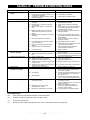
Section 6: TROUBLESHOOTING GUIDE
SYMPTOM
1.
2.
3.
POSSIBLE CAUSE
Low Battery message on
keypad.
Periodic beep(s) from keypad.
False alarms.
1a. System battery is low or missing.
1b. Low battery on transmitter (Low batt + zone
number will be displayed).
1c. Low battery on wireless keypad (Low batt +
00 will be displayed).
2.
System is in TEST mode.
3a. Sensors not properly installed, wired, or
monitored.
3b. Protected door or window opened while
system armed.
3c. Improper user operation of exit/entry delays.
3d. Magnets located too far from switches,
and/or doors and windows not properly
aligned.
3e. Magnetic contacts improperly connected or
wire broken.
3f.
Entry door programmed as "instant".
3g. Loose fitting door or window being rat tled
by wind or vibrations.
3h. Dust, dirt in sensing chamber of smoke
detector.
3i. Improper location of smoke detector.
4.
3j. Unit malfunctioning.
4a. Interrupted AC power supply.
"AC POWER" light off or
"NO AC" displayed.
4b. Wire run from transformer to control is too
long.
5.
6.
7.
Digital communicator message not being received.
5a.
5b.
5c.
5d.
System in TEST mode.
Telephone connection not secure.
Digital communicator malfunctioning.
Telephone number in program needs prefix
or access code.
5e. Telephone call to central monitoring station
requires operator assistance.
6.
System not ready (zones faulted)..
7a. "CC" displayed.
Does not arm.
Control doesn't respond to
keystrokes on keypad.
7b. "dl" displayed.
7c.
8.
"Check 09" is displayed.
"OC" displayed.
8a. No communication between wireless
receiver and control.
8b. Wireless receiver has not heard
transmission for 12 hours.
8c.
Keyswitch is enabled but not connected.
REMEDY
1a. Check system battery.
1b. Check battery in transmitter.
1c.
Check battery in wireless keypad.
2.
Enter "Code" + OFF to exit TEST mode.
3a. Check installation to see if in accordance
with established procedure.
3b. Check with all occupants of protected
home.
3c. Check setting of entry delay . Exit delay is
15 seconds longer than the entry delay
time. Remind user of same.
3d. Check all openings for proper switch and
magnet orientation.
3e. Check wiring connections. Be sure wires
are properly stripped and tightly fastened to
screw terminals.
3f. Check and revise program. Reprogram
transmitter number.
3g. Mount magnet closer to contact.
3h. Clean unit's sensing chamber with vacuum
cleaner per unit's instructions.
3i. See unit's instructions for locations to
avoid. Relocate as necessary.
3j. Replace detector.
4a. Check transformer connection and power
line circuit breaker.
4b. Make sure wiring run is not longer than the
recommended length-per-gauge (see pg.10)
5a. Remove from TEST mode.
5b. Check all connections.
5c. Check with a different 4110.
5d. Program prefix or access code into 4110.
5e. 4110 system cannot work in this situa tion.
6.
Bypass faulted zones, then arm.
7a. System is in communication with down loader at central station. Wait until down load session is finished.
7b. System has just been powered and is in its
one minute initialization. To by pass this
time, press '#' + '0'.
7c. No communication between keypad and
control. Check proper keypad connections.
8a. Check for broken connection or miswiring
of receiver to control.
Check that DIP switches on receiver are all
"OFF" (to the right).
8b. Receiver is not operating properly. If
system was working and nothing was
changed, replace receiver.
8c. Connect keyswitch or disable keyswitch.
Special Messages:
OC:
Open Circuit (No communication between control and keypad).
EE:
Program Entry Error (Invalid entry while in program mode).
dI:
System busy, please wait.
E4:
More than 4 transmitters are programmed, but only a 4-zone wireless receiver is being used.
-14WWW.DIYALARMFORUM.COM
REGULATORY AGENCY STATEMENTS
UL NOTICE: This is a "Grade A" residential system.
FEDERAL COMMUNICATIONS COMMISSION (FCC) Part 15 STATEMENT
This equipment has been tested to FCC requirements and has been found acceptable for use. The FCC requires the
following statement for your information:
This equipment generates and uses radio frequency energy and if not installed and used properly, that is, in strict
accordance with the manufacturer's instructions, may cause interference to radio and television reception. It has been
type tested and found to comply with the limits for a Class B computing device in accordance with the specifications in
Part 15 of FCC Rules, which are designed to provide reasonable protection against such interference in a residential
installation. However, there is no guarantee that interference will not occur in a particular installation. If this
equipment does cause interference to radio or television reception, which can be determined by turning the equipment
off and on, the user is encouraged to try to correct the interference by one or more of the following measures:
• If using an indoor antenna, have a quality outdoor antenna installed.
• Reorient the receiving antenna until interference is reduced or eliminated.
• Move the radio or television receiver away from the receiver/control.
• Move the antenna leads away from any wire runs to the receiver/control.
• Plug the receiver/control into a different outlet so that it and the radio or television receiver are on different branch
circuits.
If necessary, the user should consult the dealer or an experienced radio/television technician for additional
suggestions. The user or master may find the following booklet prepared by the Federal Communications Commission
helpful:
"Interference Handbook"
This booklet is available from the U.S. Government Printing Office, Washington, DC 20402.
The user shall not make any changes or modifications to the equipment unless authorized by the Installation
Instructions or User's Manual. Unauthorized changes or modifications could void the user's authority to operate the
equipment.
FEDERAL COMMUNICATIONS COMMISSION (FCC) Part 68 STATEMENT
This equipment complies with Part 68 of the FCC rules. On the front cover of this equipment is a label that contains,
among other information, the FCC registration number and ringer equivalence number (REN) for this equipment. If
requested, this in formation must be provided to the telephone company.
This equipment uses the following jacks: An RJ31X is used to connect this equipment to the telephone network.
The REN is used to determine the quantity of devices which may be connected to the telephone line. Excessive RENs
on the telephone line may result in the devices not ringing in response to an incoming call. In most, but not all areas,
the sum of the RENs should not exceed five (5.0). To be certain of the number of devices that may be connected to the
line, as determined by the total RENs, contact the telephone company to determine the maximum REN for the calling
area.
If this equipment causes harm to the telephone network, the telephone company will notify you in advance that
temporary discontinuance of service may be required. If advance notice is not practical, the telephone company will
notify the customer as soon as possible. Also, you will be advised of your right to file a complaint with the FCC if you
believe necessary.
The telephone company may make changes in its facilities, equipment, operations, or procedures that could affect the
operation of the equipment. If this happens, the telephone company will provide advance notice in order for you to
make the neces sary modifications in order to maintain uninterrupted service.
If trouble is experienced with this equipment, please contact the manufacturer for repair and warranty information. If
the trou ble is causing harm to the telephone network, the telephone company may request you remove the equipment
from the network until the problem is resolved.
There are no user serviceable components in this product, and all necessary repairs must be made by the
manufacturer. Other repair methods may invalidate the FCC registration on this product.
This equipment cannot be used on telephone company-provided coin service. Connection to Party Line Service is
subject to state tariffs.
This equipment is hearing-aid compatible.
When programming or making test calls to an emergency number, briefly explain to the dispatcher the reason for the
call. Perform such activities in the off-peak hours; such as early morning or late evening.
-15WWW.DIYALARMFORUM.COM
CANADIAN DEPARTMENT OF COMMUNICATIONS
(DOC) STATEMENT
NOTICE
The Canadian Department of Communications label identifies certified equipment. This certification means that the
equipment meets certain telecommunications network protective, operational and safety requirements. The Department
does not guarantee the equipment will operate to the user's satisfaction.
Before installing this equipment, users should ensure that it is permissible to be connected to the facilities of the local
telecommunications company. The equipment must also be installed using an acceptable method of connection. In some
cases, the company's inside wiring as sociated with a single line individual service may be extended by means of certified
connector assembly (telephone extension cord). The customer should be aware that compliance with the above conditions
may not prevent degradation of service in some situations.
Repairs to certified equipment should be made by an authorized Canadian maintenance facility designated by the
supplier. Any repairs or al terations made by the user to this equipment, or equipment malfunctions, may give the
telecommunications company cause to request the user to disconnect the equipment.
Users should ensure for their own protection that the electrical ground connections of the power utility, telephone lines
and internal metallic water pipe system, if present, are connected together. This precaution may be particularly
important in rural areas.
Caution: User should not attempt to make such connections themselves, but should contact the appropriate electric
inspection authority, or electrician, as appropriate.
The Load Number (LN) assigned to each terminal device denotes the percentage of the total load to be connected to a
telephone loop which is used by the device, to prevent overloading. The termination on a loop may consist of any
combination of devices subject only to the require ment that the total of the Load Numbers of all the devices does not
exceed 100.
AVIS
L'étiquette du ministère des Communications du Canada identifie le matériel homologué. Cette étiquette certifie que le
matériel est conforme à certaines normes de protection, d'exploitation et de sécurité des réseaux de télécommunications.
Le ministère n'assure toutefois pas que le matériel fonctionnera à la satisfaction de l'utilisateur.
Avant d'installer ce matériel, l'utilisateur doit s'assurer qu'il est permis de le raccorder aux installations de l'entreprise
locale de télécommuni cations. Le matériel doit également être installé en suivant une méthode acceptée de
raccordement. Dans certains cas, les fils intérieurs de l'en treprise utilisés pour un service individuel à la ligne unique
peuvent être prolongés au moyen d'un dispositif homologué de raccordement (cordon prolongateur téléphonique interne).
L'abonne ne doit pas oublier qu'il est possible que la conformité aux conditions énoncées ci-dessus n'em pèche pas la
dégradation du service dans certaines situations. Actuellement, les entreprises de télécommunications ne permettent pas
que l'on raccorde leur matériel aux prises d'abonnés, sauf dans les cas precis prévus par les tarifs particuliers de ces
entreprises.
Les réparations du matériel homologué doivent être effectuées pas un centre d'entretien canadien autorisé désigné par le
fournisseur. La compagnie de télécommunications peut demander à l'utilisateur de débrancher un appareil à la suite de
réparations ou de modifications effec tuées par l'utilisateur ou à cause de mauvais fonctionnement.
Pour sa propre protection, l'utilisateur doit s'assurer que tous les fils de mise en terre de la source d'énergie électrique,
des lignes téléphoniques de réseau de conduites d'eau, s'il y en a, soient raccordés ensemble. Cette précaution est
particulièrement importante dans les régions rurales.
Avertissement: L'utilisateur ne doit pas tenter de faire ces raccordements lui-même; il doit avoir recours à un service
d'inspection des in stallations électriques, ou à un électricien, selon le cas.
L'indice de charge (IC) assigné à chaque dispositif terminal pour éviter toute surcharge indique le pourcentage de la
charge totale qui peut être raccordé à un circuit téléphonique bouclé utilisé par ce dispositif. La terminaison du circuit
bouclé peut être constituée de n'importe quelle combinaison de dispositifs, pourvu que la somme des indices de charge de
l'ensemble des dispositifs ne dépasse pas 100.
-16WWW.DIYALARMFORUM.COM
DIP SWITCH TABLES FOR 5700 RF SYSTEM WIRELESS DEVICES
HOUSE ID
SWITCH SETTING FOR ALL
DEVICES EXCEPT 5716
2
3
4
5
UP
UP
UP
UP
UP
UP
UP
UP
UP
UP
UP
UP
UP
UP
UP
—
—
—
—
—
—
—
—
—
—
—
—
—
—
—
—
UP
UP
UP
UP
UP
UP
UP
—
—
—
—
—
—
—
—
UP
UP
UP
UP
UP
UP
UP
UP
—
—
—
—
—
—
—
—
UP
UP
UP
—
—
—
—
UP
UP
UP
UP
—
—
—
—
UP
UP
UP
UP
—
—
—
—
UP
UP
UP
UP
—
—
—
—
UP
—
—
UP
UP
—
—
UP
UP
—
—
UP
UP
—
—
UP
UP
—
—
UP
UP
—
—
UP
UP
—
—
UP
UP
—
—
—
UP
—
UP
—
UP
—
UP
—
UP
—
UP
—
UP
—
UP
—
UP
—
UP
—
UP
—
UP
—
UP
—
UP
—
UP
—
16
8
4
2
1
SIDE
VIEW (UP)
UP
HOUSE ID (1 SHOWN)
SIDE
VIEW (UP)
DN
1 2 3 4 5 6
HOUSE ID (1 SHOWN)
5727 KEYPAD
1 2 3 4 5 6
SIDE
VIEW (UP)
7 8
}
DIP
XMTR
ID
DN
32
33
34
35
36
37
38
39
40
41
42
43
44
45
46
47
XMTR ID
(48 SHOWN)
HOUSE ID (1 SHOWN)
1 2 3 4 5
UP
5711/5711WM
DOOR/WINDOW TRANSMITTER
6
UP
UP
UP
UP
—
—
—
—
48
49
50
51
52
53
54
55
SIDE
VIEW
(DN)
DN
DIP SWITCH POSITION
XMTR
ID
XMTR ID
FIXED AT
“00”
IMPORTANT
SET SWITCHES WITH
BATTERY REMOVED
7
UP
UP
—
—
UP
UP
—
—
8
UP
—
UP
—
UP
—
UP
—
TERMINALS
SW4
DIP
SW3
6 5 4 3 2 1
UP
DIP
SW4
SIDE
VIEW (UP)
HOUSE ID (1 SHOWN)
1 2 3 4 5 6
SIDE
VIEW
(DN)
7 8 9 10 11 12
XMTR ID (33 SHOWN)
HOUSE ID (1 SHOWN)
UP
}
}
XMTR ID
POS.1: UP = NORMAL RESPONSE
(33 SHOWN)
DN = FAST RESPONSE
POS. 2: UP = NO COVER TAMPER
DN = COVER TAMPER (use N.C. setting)
XMTR
ID
1
2
3
4
5
6
7
8
9
10
11
12
13
14
15
16
17
18
19
20
21
22
23
24
25
26
27
28
29
30
31
32
BIT
VALUE:
6 5 4 3 2 1
DN
UP
POS.12: UP = N.O.
— = N.C
(Avoid ID 32-37 with N.O.)
UP
SW3
DN
POS. 6: UP = N.O.
DN = N.C.
DIP SWITCH POSITION
6
UP
UP
UP
UP
UP
UP
UP
UP
UP
UP
UP
UP
UP
UP
UP
UP
UP
UP
UP
UP
UP
UP
UP
UP
UP
UP
UP
UP
UP
UP
UP
—
7
UP
UP
UP
UP
UP
UP
UP
UP
UP
UP
UP
UP
UP
UP
UP
—
—
—
—
—
—
—
—
—
—
—
—
—
—
—
—
UP
8
UP
UP
UP
UP
UP
UP
UP
—
—
—
—
—
—
—
—
UP
UP
UP
UP
UP
UP
UP
UP
—
—
—
—
—
—
—
—
UP
9
UP
UP
UP
—
—
—
—
UP
UP
UP
UP
—
—
—
—
UP
UP
UP
UP
—
—
—
—
UP
UP
UP
UP
—
—
—
—
UP
10
UP
—
—
UP
UP
—
—
UP
UP
—
—
UP
UP
—
—
UP
UP
—
—
UP
UP
—
—
UP
UP
—
—
UP
UP
—
—
UP
11
—
UP
—
UP
—
UP
—
UP
—
UP
—
UP
—
UP
—
UP
—
UP
—
UP
—
UP
—
UP
—
UP
—
UP
—
UP
—
UP
32
16
8
4
2
1
XMTR
ID
33
34
35
36
37
38
39
40
41
42
43
44
45
46
47
48
49
50
51
52
53
54
55
56
57
58
59
60
61
62
63
BIT
VALUE
DIP SWITCH POSITION
6
—
—
—
—
—
—
—
—
—
—
—
—
—
—
—
—
—
—
—
—
—
—
—
—
—
—
—
—
—
—
—
7
UP
UP
UP
UP
UP
UP
UP
UP
UP
UP
UP
UP
UP
UP
UP
—
—
—
—
—
—
—
—
—
—
—
—
—
—
—
—
8
UP
UP
UP
UP
UP
UP
UP
—
—
—
—
—
—
—
—
UP
U
UP
UP
UP
UP
UP
UP
—
—
—
—
—
—
—
—
9
UP
UP
UP
—
—
—
—
UP
UP
UP
UP
—
—
—
—
UP
UP
UP
UP
—
—
—
—
UP
UP
UP
UP
—
—
—
—
10
UP
—
—
UP
UP
—
—
UP
UP
—
—
UP
UP
—
—
UP
UP
—
—
UP
UP
—
—
UP
UP
—
—
UP
UP
—
—
11
—
UP
—
UP
—
UP
—
UP
—
UP
—
UP
—
UP
—
UP
—
UP
—
UP
—
UP
—
UP
—
UP
—
UP
—
UP
—
32
16
8
4
2
1
HOUSE
ID
1
2
3
4
5
6
7
8
9
10
11
12
13
14
15
16
17
18
19
20
21
22
23
24
25
26
27
28
29
30
31
BIT
VALUE:
DN
UP = PULSE COUNT
— = INST. MODE
DIP SWITCH POSITION
6
UP
UP
UP
UP
UP
UP
UP
UP
—
—
—
—
—
—
—
—
7
UP
UP
UP
UP
—
—
—
—
UP
UP
UP
UP
—
—
—
—
8
UP
UP
—
—
UP
UP
—
—
UP
UP
—
—
UP
UP
—
—
9
UP
—
UP
—
UP
—
UP
—
UP
—
UP
—
UP
—
UP
—
5716 DOOR/WINDOW TRANSMITTER
DIP
2
XMTR ID
(32 SHOWN)
UP
TERMINAL
BLOCK
1
7 8 9 10
UP
POS.6 UP= XMTR ID 62
DN= XMTR ID 63
DIP
DIP
MIRROR
DIP
DIP
DIP
1 2 3 4 5 6
5715
UNIVERSAL TRANSMITTER
5775 PIR
DETECTOR/TRANSMITTER
}
1
1
2
3
4
5
6
7
8
9
10
11
12
13
14
15
16
17
18
19
20
21
22
23
24
25
26
27
28
29
30
31
5706/5707 SMOKE
DETECTORTRANSMITTER
HOUSE ID (1 SHOWN)
DIP SWITCH POSITION
DEVICE
ID
BIT
VALUE:
5701 PANIC TRANSMITTER
DIP SWITCH POSITION
5
—
UP
—
UP
—
UP
—
UP
—
UP
—
UP
—
UP
—
UP
—
UP
—
UP
—
UP
—
UP
——
UP
—
UP
—
UP
—
4
UP
—
—
UP
UP
—
—
UP
UP
—
—
UP
UP
—
—
UP
UP
—
—
UP
UP
—
—
UP
UP
—
—
UP
UP
—
—
3
UP
UP
UP
—
—
—
—
UP
UP
UP
UP
—
—
—
—
UP
UP
UP
UP
—
—
—
—
UP
UP
UP
UP
—
—
—
—
2
UP
UP
UP
UP
UP
UP
UP
—
—
—
—
—
—
—
—
UP
UP
UP
UP
UP
UP
UP
UP
—
—
—
—
—
—
—
—
1
UP
UP
UP
UP
UP
UP
UP
UP
UP
UP
UP
UP
UP
UP
UP
—
—
—
—
—
—
—
—
—
—
—
—
—
—
—
—
1
2
4
8
16
TRANSMITTER
ID
1
2
3
4
5
6
7
8
9
10
11
12
13
14
15
16
17
18
19
20
21
22
23
24
25
26
27
28
29
30
31
32
33
34
35
36
37
38
39
40
41
42
43
44
45
46
47
48
49
50
51
52
53
54
55
56
57
58
59
60
61
62
63
BIT
VALUE:
DIP SWITCH POSITION
6
—
UP
—
UP
—
UP
—
UP
—
UP
—
UP
—
UP
—
UP
—
UP
—
UP
—
UP
—
UP
—
UP
—
UP
—
UP
—
UP
—
UP
—
UP
—
UP
—
UP
—
UP
—
UP
—
UP
—
UP
—
UP
—
UP
—
UP
—
UP
—
UP
—
UP
—
UP
—
5
UP
—
—
UP
UP
—
—
UP
UP
—
—
UP
UP
—
—
UP
UP
—
—
UP
UP
—
—
UP
UP
—
—
UP
UP
—
—
UP
UP
—
—
UP
UP
—
—
UP
UP
—
—
UP
UP
—
—
UP
UP
—
—
UP
UP
—
—
UP
UP
—
—
UP
UP
—
—
4
UP
UP
UP
—
—
—
—
UP
UP
UP
UP
—
—
—
—
UP
UP
UP
UP
—
—
—
—
UP
UP
UP
UP
—
—
—
—
UP
UP
UP
UP
—
—
—
—
UP
UP
UP
UP
—
—
—
—
UP
UP
UP
UP
—
—
—
—
UP
UP
UP
UP
—
—
—
—
3
UP
UP
UP
UP
UP
UP
UP
—
—
—
—
—
—
—
—
UP
UP
UP
UP
UP
UP
UP
UP
—
—
—
—
—
—
—
—
UP
UP
UP
UP
UP
UP
UP
UP
—
—
—
—
—
—
—
—
UP
UP
UP
UP
UP
UP
UP
UP
—
—
—
—
—
—
—
—
2
UP
UP
UP
UP
UP
UP
UP
UP
UP
UP
UP
UP
UP
UP
UP
—
—
—
—
—
—
—
—
—
—
—
—
—
—
—
—
UP
UP
UP
UP
UP
UP
UP
UP
UP
UP
UP
UP
UP
UP
UP
UP
—
—
—
—
—
—
—
—
—
—
—
—
—
—
—
—
1
UP
UP
UP
UP
UP
UP
UP
UP
UP
UP
UP
UP
UP
UP
UP
UP
UP
UP
UP
UP
UP
UP
UP
UP
UP
UP
UP
UP
UP
UP
UP
—
—
—
—
—
—
—
—
—
—
—
—
—
—
—
—
—
—
—
—
—
—
—
—
—
—
—
—
—
—
—
—
1
2
4
8
16
32
For 5700 series transmitters not shown in this table, refer to the instructions accompanying each transmitter.
-17WWW.DIYALARMFORUM.COM
WARNING
THE LIMITATIONS OF THIS ALARM SYSTEM
While this System is an advanced design security system, it does not offer guaranteed protection against burglary, fire or
other emergency. Any alarm system, whether commercial or residential, is sub ject to compromise or failure to warn for a
vari ety of reasons. For example:
• Intrusion detectors (e.g., passive infrared detectors), smoke detectors, and many other sensing devices will not work
with out power. Battery-operated devices will not work without batteries, with dead batteries, or if the batteries are
not put in properly. Devices powered solely by AC will not work if their AC power supply is cut off for any reason,
however briefly.
• Signals sent by wireless transmitters may be blocked or reflected by metal before they reach the alarm receiver. Even
if the signal path has been recently checked during a weekly test, blockage can occur if a metal object is moved into
the path.
• A user may not be able to reach a panic or emergency button quickly enough.
• While smoke detectors have played a key role in reducing residential fire deaths in the United States, they may not
activate or provide early warning for a variety of reasons in as many as 35% of all fires, according to data published
by the Federal Emergency Management Agency. Some of the reasons smoke detectors used in conjunction with this
System may not work are as follows. Smoke detectors may have been improperly installed and positioned. Smoke
detectors may not sense fires that start where smoke cannot reach the detectors, such as in chimneys, in walls, or
roofs, or on the other side of closed doors. Smoke detectors also may not sense a fire on another level of a residence or
building. A second floor detector, for ex ample, may not sense a first floor or basement fire. Finally, smoke detectors
have sensing limitations. No smoke detector can sense every kind of fire every time. In general, detectors may not
always warn about fires caused by carelessness and safety hazards like smoking in bed, violent explosions, escaping
gas, improper storage of flammable materials, overloaded electrical circuits, children playing with matches, or arson.
Depending on the nature of the fire and/or location of the smoke detectors, the detector, even if it operates as
anticipated, may not pro vide sufficient warning to allow all occupants to escape in time to prevent injury or death.
• Passive Infrared Motion Detectors can only detect intrusion within the designed ranges as diagrammed in their
installation manual. Passive Infrared Detectors do not provide volumetric area protection. They do create multiple
beams of protection, and intrusion can only be detected in unobstructed areas covered by those beams. They cannot
detect motion or intrusion that takes place behind walls, ceilings, floors, closed doors, glass partitions, glass doors, or
windows. Mechanical tamper ing, masking, painting or spraying of any material on the mirrors, windows or any part
of the optical system can reduce their detec tion ability. Passive Infrared Detectors sense changes in temperature;
however, as the ambient temperature of the protected area approaches the temperature range of 90° to 105°F (32° to
40°C), the detection performance can decrease.
• Alarm warning devices such as sirens, bells or horns may not alert people or wake up sleepers if they are located on
the other side of closed or partly open doors. If warning devices are located on a different level of the residence from
the bedrooms, then they are less likely to waken or alert people inside the bedrooms. Even persons who are awake
may not hear the warning if the alarm is muffled by noise from a stereo, radio, air conditioner or other appliance, or
by passing traffic. Fi nally, alarm warning devices, however loud, may not warn hearing-impaired people.
• Telephone lines needed to transmit alarm signals from a premises to a central monitoring station may be out of
service or temporarily out of service. Telephone lines are also subject to compromise by sophisticated intruders.
• Even if the system responds to the emergency as intended, however, occupants may have insuffi cient time to protect
themselves from the emergency situation. In the case of a monitored alarm sys tem, authorities may not respond
appropri ately.
• This equipment, like other electrical devices, is subject to component failure. Even though this equipment is designed
to last as long as 20 years, the electronic components could fail at any time.
The most common cause of an alarm system not functioning when an intrusion or fire occurs is inadequate maintenance.
This alarm system should be tested weekly to make sure all sensors and transmitters are working properly. The security
keypad (and remote keypad) should be tested as well.
Wireless transmitters (used in some systems) are designed to provide long battery life under normal operating
conditions. Longevity of batteries may be as much as 4 to 7 years, depending on the environment, usage, and the specific
wireless device being used. External factors such as humidity, high or low temperatures, as well as large swings in
temperature, may all reduce the actual battery life in a given installation. This wireless system, however, can identify a
true low battery situation, thus allowing time to arrange a change of battery to maintain protection for that given point
within the system.
Installing an alarm system may make the owner eligible for a lower insurance rate, but an alarm system is not a
substitute for insurance. Homeowners, property owners and renters should continue to act prudently in protecting
themselves and continue to insure their lives and property.
We continue to develop new and improved protection devices. Users of alarm systems owe it to themselves and their
loved ones to learn about these developments.
-18WWW.DIYALARMFORUM.COM
FUSE
FOR REPLACEMENT,
USE SAME VALUE
+
No. 4116
ARMING/DISARMING
KEYSWITCH
(SINGLE LED, LOCKSWITCH,
TAMPER)
–
No. 4281L or 4281M
RF RECEIVER
WIRELESS ZONES
4281L: UP TO 4
4281M: UP TO 8
OR
CONNECTOR TABS
–
+
6
7
8
9
10
11
12
LO
5
13
14
15
16
ALARM OUTPUT
10.5-13.8VDC, 2A MAX.
(600mA MAX FOR UL USAGE,
INCLUDING AUX. POWER)
STEADY FOR BURGLARY/PANIC,
PULSING FOR FIRE (e.g. USE ADEMCO
No. 702 OR 719 SIREN, OR 12V BELL)
CONNECTION OF THE FIRE ALARM SIGNAL TO A FIRE
ALARM HEADQUARTERS OR A CENTRAL STATION
SHALL BE PERMITTED ONLY WITH THE PERMISSION
OF THE LOCAL AUTHORITY HAVING JURISDICTION.
THE BURGLAR ALARM SIGNAL SHALL NOT BE CONNECTED TO A POLICE EMERGENCY NUMBER.
18
19
20
RING
TIP
(GRAY) (GREEN)
RING
(RED)
21
LOCATED AT
LOWER RIGHT OF
CIRCUIT BOARD
No. 4127:
No. 4137AD:
No. 6127:
No. 6128:
No. 6137:
OR
No. 5330:
20mA
60mA
20mA
30mA
85mA
105mA
INCOMING
PHONE LINE
ZONE 6
ZONE 5
ZONE 4
ZONE 3
ZONE 2
TELEPHONE WIRING
(VIA RJ31X* JACK DIRECT
CONNECT CORD)
*IN CANADA, CA38A JACK
ZONE 1
YELLOW: DATA OUT TO KEYPAD
GREEN: DATA IN FROM KEYPAD
REMOTE
KEYPAD
+ –
*IF PROGRAMMED FOR FIRE
HANDSET
RED: KEYPAD PWR (+)
PLUG-IN TRANSFORMER
16.5VAC, 25VA
(e.g. ADEMCO
No. 1321/TF2.
USE No. 1321CN
IN CANADA
BLACK: KEYPAD GROUND (–) RETURN
NOTE:
KEYPAD
CURRENT MUST
BE INCLUDED IN
AUX. CURRENT
DRAIN
CALCULATIONS
•
1000
OHMS
EOLR •
}
}
TO 110VAC
UNSWITCHED
OUTLET (24HR)
17
TIP
(BROWN)
AUX. POWER
OUTPUT
10.5-13.8VDC
500mA MAX.
INTERRUPTS
FOR FIRE
ALARM RESET
FOR COMPLETE
INFORMATION, SEE
INSTRUCTIONS
N5478V4
VIOLET
EOL
POWER
SUPERVISION
RELAY
MODULE
A77-716B
HEAT
DETECTOR
-
HI
4
HI
3
LO
2
LO
1
HI
USE UL LISTED
LIMITED ENERGY
CABLE FOR ALL
CONNECTIONS
•
+
ZONE 5*
BLK
RED
GRN
YEL
}
-19WWW.DIYALARMFORUM.COM
BLK
RED
GRN
YEL
TO DETERMINE TOTAL STANDBY LOAD
ON BATTERY, ADD 100mA TO TOTAL OF
AUX. POWER OUTPUT AND REMOTE
KEYPAD CURRENTS.
•
-
HI
RED
LO
+
+ RED
BLK –
4-WIRE SMOKE
OR COMBUSTION
DETECTOR
LO
BLACK
4
+
HI
BATTERY
12V, 4AH
OR 12V, 1.2AH
–
5
-
OPTIONAL
HI
CHARGING
VOLTAGE
13.8VDC
+
3A
{
BATTERY
(e.g. No. 90-12)
AUX PWR
OUTPUT
TERMS
SET RECEIVER’S DIP SWITCH
FOR DEVICE ADDRESS OF “0”
SEE RECEIVER’S INSTRUCTIONS
LO
GEL LEAD ACID TYPE.
BATTERY NORMALLY NEED NOT BE
REPLACED FOR AT LEAST 3 YRS.
BATTERY CAPACITY FOR EMERGENCY
STANDBY USE AT LEAST 4 HOURS.
1000
1000
1000
1000
1000
1000
OHMS
OHMS
OHMS
OHMS
OHMS
OHMS
EOLR
EOLR
EOLR
EOLR
EOLR
EOLR
• MAXIMUM LOOP RESISTANCE (EACH ZONE) 300 OHMS (PLUS EOLR)
• RESPONSE, ZONES 1-6: 300-500MSEC
• ZONE 3 CAN BE PROGRAMMED FOR N.C. SENSOR FAST RESPONSE TO AN
OPEN: 10MSEC MAX
• ZONE 5 CAN BE PROGRAMMED FOR USE AS A FIRE ZONE. SEE DIAGRAM
THIS DEVICE COMPLIES WITH PART 15 OF FCC RULES. OPERATION
IS SUBJECT TO THE FOLLOWING TWO CONDITIONS: (1) IT MAY NOT
CAUSE HARMFUL INTERFERENCE, (2) IT MUST ACCEPT ANY INTERFERENCE THAT MAY CAUSE UNDESIRED OPERATION.
NOTE: MULTIPLE KEYPADS MAY BE
USED, BUT EACH 5330 KEYPAD
MUST BE ON AN INDIVIDUAL HOME
RUN. USE MAX. OF 220FT. OF #22
WIRE OR 550 FT. OF #18 WIRE.
COMPLIES WITH FCC RULES, PART 68
FCC REGISTRATION NO. AC398U-68192-AL-E
RINGER EQUIVALENCE: 0.7B.
WARNING:
EARTH GROUND
SEE INSTRUCTIONS
FOR PROPER GROUNDING
DOC LOAD NO.: 3
WARNING:
TO PREVENT RISK OF SHOCK,
DISCONNECT TELEPHONE LINE
AT TELCO JACK BEFORE
SERVICING THIS UNIT.
THIS EQUIPMENT SHOULD BE INSTALLED IN
ACCORDANCE WITH THE NATIONAL FIRE PROTECTION ASSOCIATION’S STANDARD 74 (NATIONAL FIRE PROTECTION ASSOC., BATTERYMARCH
PARK, QUINCY, MA 02269). PRINTED INFORMATION DESCRIBING PROPER INSTALLATION,
OPERATION, TESTING, MAINTENANCE, EVACUATION PLANNING AND REPAIR SERVICE IS TO BE
PROVIDED WITH THIS EQUIPMENT.
OWNER’S INSTRUCTION NOTICE NOT TO BE
REMOVED. WEEKLY TESTING IS REQUIRED TO
ENSURE PROPER OPERATION OF THIS SYSTEM.
ADEMCO LIMITED WARRANTY
Alarm Device Manufacturing Company, a Division of Pittway Corporation, and its divisions, subsidiaries
and affiliates ("Seller"), 165 Eileen Way, Syosset, New York 11791, warrants its products to be in
conformance with its own plans and specifications and to be free from defects in materials and
workmanship under normal use and service for 24 months from the date stamp control on the product or,
for products not having an Ademco date stamp, for 12 months from date of original purchase unless the
installation instructions or catalog sets forth a shorter period, in which case the shorter period shall
apply. Seller's obligation shall be limited to repairing or replacing, at its option, free of charge for
materials or labor, any product which is proved not in compliance with Seller's specifications or proves
defective in materials or workmanship under normal use and service. Seller shall have no obligation under this Limited Warranty or otherwise if the product is altered or improperly repaired or serviced by
anyone other than Ademco factory service. For warranty service, return product transportation prepaid,
to Ademco Factory Service, 165 Eileen Way, Syosset, New York 11791.
THERE ARE NO WARRANTIES, EXPRESS OR IMPLIED, OF MERCHANTABILITY, OR FITNESS
FOR A PARTICULAR PURPOSE OR OTHERWISE, WHICH EXTEND BEYOND THE DESCRIPTION
ON THE FACE HEREOF. IN NO CASE SHALL SELLER BE LIABLE TO ANYONE FOR ANY
CONSEQUENTIAL OR INCIDENTAL DAMAGES FOR BREACH OF THIS OR ANY OTHER
WARRANTY, EXPRESS OR IMPLIED, OR UPON ANY OTHER BASIS OF LIABILITY
WHATSOEVER, EVEN IF THE LOSS OR DAMAGE IS CAUSED BY THE SELLER'S OWN
NEGLIGENCE OR FAULT.
Seller does not represent that the products it sells may not be compromised or circumvented; that the
products will prevent any personal injury or property loss by burglary, robbery, fire or otherwise; or that
the products will in all cases provide adequate warning or protection. Customer understands that a
properly installed and maintained alarm may only reduce the risk of a burglary, robbery, fire or other
events occurring without providing an alarm, but it is not insurance or a guarantee that such will not
occur or that there will be no personal injury or property loss as a result. CONSEQUENTLY, SELLER
SHALL HAVE NO LIABILITY FOR ANY PERSONAL INJURY, PROPERTY DAMAGE OR OTHER
LOSS BASED ON A CLAIM THE PRODUCT FAILED TO GIVE WARNING. HOWEVER, IF SELLER
IS HELD LIABLE, WHETHER DIRECTLY OR INDIRECTLY, FOR ANY LOSS OR DAMAGE ARISING
UNDER THIS LIMITED WARRANTY OR OTHERWISE, REGARDLESS OF CAUSE OR ORIGIN,
SELLER'S MAXIMUM LIABILITY SHALL NOT IN ANY CASE EXCEED THE PURCHASE PRICE OF
THE PRODUCT, WHICH SHALL BE THE COMPLETE AND EXCLUSIVE REMEDY AGAINST
SELLER. This warranty replaces any previous warranties and is the only warranty made by Seller on
this product. No increase or alteration, written or verbal, of the obligations of this Limited Warranty is
authorized.
ALARM DEVICE MANUFACTURING CO.
A DIVISION OF PITTWAY CORPORATION
165 Eileen Way, Syosset, New York 11791
Copyright © 1996
N5478V5 7/96
WWW.DIYALARMFORUM.COM