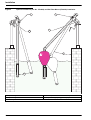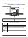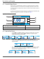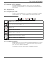
1
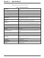
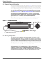
Catalog Number 5790018
LDO™ Dissolved Oxygen Sensor
USER MANUAL
December 2006, Edition 6
© Hach Company, 2003–2006. All rights reserved. Printed in the U.S.A. eac/te/dp
Visit http://www.hach.com
Table of Contents
Section 1 Specifications......................................................................................................................................... 5
Section 2 General Information ............................................................................................................................... 7
2.1 Safety Information ............................................................................................................................................... 7
2.1.1 Use of Hazard Information......................................................................................................................... 7
2.1.2 Precautionary Labels................................................................................................................................. 7
2.2 General Sensor Information ................................................................................................................................ 8
2.3 Theory of Operation ............................................................................................................................................ 8
Section 3 Installation .............................................................................................................................................. 9
3.1 Connecting/Wiring the Sensor to the sc100 Controller ....................................................................................... 9
3.1.1 Connecting the sc Sensor in a Non-hazardous Location .......................................................................... 9
3.1.1.1 Attaching a sc Sensor with a Quick-connect Fitting ......................................................................... 9
3.1.1.2 Hard-wiring a sc Sensor to the Controller ...................................................................................... 10
3.1.2 Connecting the sc Sensor to a Controller in a Hazardous Location ........................................................ 12
3.1.2.1 Attaching a sc Sensor with a Quick-connect Fitting in a Hazardous Location ............................... 12
3.2 Connecting the Sensor to the sc1000 ............................................................................................................... 13
3.2.1 Connecting the Sensor using the Quick-connect Fittings ........................................................................ 13
3.3 Installing the Sensor in the Sample Stream ...................................................................................................... 13
Section 4 User Interface and Navigation ............................................................................................................ 15
4.1 Using the sc100 Controller................................................................................................................................ 15
4.1.1 Controller Display Features ..................................................................................................................... 16
4.1.2 Important Key Presses ............................................................................................................................ 16
4.2 Using the sc1000 Controller.............................................................................................................................. 17
4.2.1 Display Features...................................................................................................................................... 17
4.2.1.1 Using the Pop-up Toolbar .............................................................................................................. 17
4.2.1.2 Using the Menu Windows .............................................................................................................. 17
4.2.1.3 Navigating the Menu Windows....................................................................................................... 18
Section 5 Operation .............................................................................................................................................. 21
5.1 Sensor Setup .................................................................................................................................................... 21
5.2 Sensor Data Logging ........................................................................................................................................ 21
5.3 Sensor Diagnostics Menu ................................................................................................................................. 21
5.4 Sensor Setup Menu .......................................................................................................................................... 22
5.5 Pressure and Elevation ..................................................................................................................................... 23
5.5.1 Selecting Atmospheric Pressure ............................................................................................................. 23
5.6 Calibration ......................................................................................................................................................... 24
5.6.1 Calibration in Air ...................................................................................................................................... 24
5.6.2 Sample Cal—Calibration by Comparison to a Winkler Titration .............................................................. 25
5.6.3 Sample Cal—Calibration by Comparison to a Hand-held DO Analyzer .................................................. 25
5.6.4 Concurrent Calibration of Two Sensors ................................................................................................... 26
Section 6 Maintenance ......................................................................................................................................... 27
6.1 Maintenance Schedule ..................................................................................................................................... 27
6.2 Cleaning the Sensor ......................................................................................................................................... 27
Section 7 Troubleshooting ................................................................................................................................... 29
7.1 Error Codes....................................................................................................................................................... 29
7.2 Warnings ........................................................................................................................................................... 29
3
Table of Contents
Section 8 Replacement Parts and Accessories.................................................................................................. 31
Section 9 How to Order ......................................................................................................................................... 33
Section 10 Repair Service..................................................................................................................................... 34
Section 11 Limited Warranty ................................................................................................................................ 35
Section 10 Compliance Information .................................................................................................................... 37
4
Section 1
Specifications
Specifications are subject to change without notice.
Table 1 LDO Probe Specifications
Components
Corrosion-resistant materials, fully-immersible sensor with 10 m (30 foot)
cable
Measuring Range (Dissolved Oxygen)
0 to 20.00 ppm (0 to 20.00 mg/L) or 0 to 200% saturation
Measuring Range (Temperature)
0 to 50 °C (32 to 122 °F)
Measurement Accuracy
Below 1 ppm: ± 0.1; Above 1 ppm: ±0.2
Temperature Accuracy
±0.2 °C
Repeatability
±0.5% of span
Response Time
To 90% in less than 40 seconds
To 95% in less than 60 seconds
Resolution
Below 10 ppm: ±0.07 ppm or mg/L, ±0.1% saturation
Above 10 ppm: ±0.01 ppm or mg/L, ±0.1% saturation
Interferences
No interferences from the following: H2S, pH, K+1, Na+1, Mg+2, Ca+2, NH4+1,
Al+3, Pb+2, Cd+2, Zn+2, Cr (tot), Fe+2, Fe+3, Mn+2, Cu+2, Mi+2, Co+2, CN–1,
NO3–1, SO4–2, S–2, PO4+3, Cl–1, Anion Active Tensides, Crude Oils, Cl2–1
Probe Operating Temperature
0 to 50 °C (32 to 122 °F)
Probe Storage Temperature
–20 to 70 °C (–4 to 158 °F); 95% relative humidity, non-condensing.
Minimum Flow Rate
Non required
Sensitivity
±0.5% of span
Calibration/Verification
Air Calibration: one point, 100% water saturated air; Sample Calibration:
comparison to standard instrument, or comparison to Winkler Titration
method
Probe Immersion Depth and Pressure Limits Submersible to 107 m (350 ft)/1050 kPa (150 psi)
Sensor Interface
Modbus
Sensor Cable
10 m (30 ft) integral cable with quick-disconnect type plug. Additional cable
length may be added by using a junction box. Up to 100 m with extension
cables.
Up to 1000 m using the Junction box.
Probe Weight
1.4 kg (3 lb, 2 oz.)
Probe Dimensions
60 x 292 mm (2.4 x 11.5 inch)
Warranties
Probe: 3 years
Sensor Cap: 1 year
5
Visit us at www.hach.com
Section 2
General Information
2.1 Safety Information
Please read this entire manual before unpacking, setting up, or operating this equipment.
Pay attention to all danger and caution statements. Failure to do so could result in serious
injury to the operator or damage to the equipment.
To ensure that the protection provided by this equipment is not impaired, do not use or
install this equipment in any manner other than that specified in this manual.
This product is acceptable for use in a Hazardous Location when used with an
sc100 Controller and installed per Control Drawing 5860078 as described in the
sc100 Controller Manual, Cat. No. 5860018.
2.1.1 Use of Hazard Information
DANGER
Indicates a potentially or imminently hazardous situation which, if not avoided,
could result in death or serious injury.
CAUTION
Indicates a potentially hazardous situation that may result in minor or moderate
injury.
Important Note: Information the requires special emphasis.
Note: Information that supplements points in the main text.
2.1.2 Precautionary Labels
Read all labels and tags attached to the instrument. Personal injury or damage to the
instrument could occur if not observed.
This symbol, if noted on the instrument, references the instruction manual for operation
and/or safety information.
This symbol, when noted on a product enclosure or barrier, indicates that a risk of electrical shock and/or
electrocution exists.
This symbol, if noted on the product, indicates the need for protective eye wear.
This symbol, when noted on the product, identifies the location of the connection for Protective Earth
(ground).
This symbol, when noted on the product, identifies the location of a fuse or current limiting device.
7
General Information
2.2 General Sensor Information
The Luminescent Dissolved Oxygen (LDO) Sensor (Figure 1) allows aqueous samples to
be easily and accurately analyzed for dissolved oxygen concentration. Specially designed
for municipal and industrial wastewater applications, the system consists of a controller
with an integrated display, and a sensor (probe with sensor cap) for in-situ measurement.
The LDO sensor can be operated using the sc100 controller and the sc1000 controller.
Refer to Operation on page 15 and sc1000 Operation on page 25 for more information.
Optional equipment, such as mounting hardware for the sensor, is supplied with an
instruction sheet for all user installation tasks. Several mounting options are available,
allowing the sensor to be adapted for use in many different applications.
Typical applications include aeration basins, nutrient removal in equalization basins,
aerobic and anaerobic digesters, effluent streams, rivers, lakes, and fish ponds.
Figure 1
LDO Sensor Dimensions
2.3 Theory of Operation
The sensor in the cap is coated with a luminescent material. Blue light from an LED
illuminates the luminescent chemical on the surface of the sensor cap. The luminescent
chemical instantly becomes excited and then as the excited chemical relaxes, it releases
red light. The red light is detected by a photodiode and the time it takes for the chemical to
return to a relaxed state is measured. The higher the oxygen concentration, the less red
light is given off by the sensor and the shorter time it takes for the luminescent material to
return to a relaxed state. The oxygen concentration is inversely proportional to the time it
takes for the luminescent material to return to a relaxed state.
Unlike electrochemical dissolved oxygen sensor technologies, the Luminescent Dissolved
Oxygen (LDO) sensor does not consume oxygen. It does not require frequent
recalibration or frequent cleaning (except when associated with consumptive slimes),
resulting in longer sensor life and more stable and accurate readings. The system is also
flow-independent so measurements can be made in applications with low or no flow.
8
Section 3
Installation
DANGER
Only qualified personnel should conduct the tasks described in this section of the
manual.
DANGER
Seul un technicien qualifié peut effectuer les tâches d'installation décrites dans
cette section du manuel.
The LDO system can be used with either an sc100 or sc1000 controller. Refer to
section 3.1 for sc100 installation instructions and section 3.2 on page 13 for sc1000
installation instructions.
3.1 Connecting/Wiring the Sensor to the sc100 Controller
DANGER
The sc100 and certain versions of the sensor are suitable for use in Class 1,
Division 2, Groups A, B, C, D Hazardous Locations . See Control Drawing 5860078 in
the sc100 Controller Manual, Cat. No. 5860018 for acceptable sensor versions and
installation requirements.
DANGER
Le sc100 et certaines versions du capteur peuvent être utilisés dans des endroits
dangereux de la Classe 1, Division 2, Groupes A, B, C, D. Reportez-vous au schéma
de contrôle 5860078 du Manuel du contrôleur sc100, Réf. 5860018 pour connaître
les versions des capteurs admises et les conditions d'installation.
3.1.1 Connecting the sc Sensor in a Non-hazardous Location
3.1.1.1 Attaching a sc Sensor with a Quick-connect Fitting
Important Note: The standard quick-connect fitting is NOT suitable for Class 1, Division 2
Hazardous Location installations without the connector lock installed, see section 3.1.2 on
page 12 for more information.
The sensor cable is supplied with a keyed quick-connect fitting for easy attachment to the
controller (Figure 2). Retain the connector cap to seal the connector opening in case the
sensor must be removed. Optional extension cables may be purchased to extend the
sensor cable length. If the total cable length exceeds 100 m (300 ft), a termination box
must be installed.
Note: Use of a load termination box other than Cat. No. 5867000 may result in a hazard. The load
termination box cannot be used in a hazardous location.
9
Installation
Figure 2
Attaching the Sensor using the Quick-connect Fitting
3.1.1.2 Hard-wiring a sc Sensor to the Controller
Important Note: Hard-wiring the sensor to the sc100 is not an approved method for
Class I, Division 2 Hazardous Locations.
1. Disconnect power to the controller if powered.
2. Open the controller cover.
3. Disconnect and remove the existing wires between the quick-connect and terminal
strip J5, see Figure 3 on page 11.
4. Remove the quick-connect fitting and wires and install the threaded plug on the
opening to maintain the environmental rating.
5. Cut the connector from the sensor cable.
6. Strip the insulation on the cable back 1-inch. Strip ¼-inch of each individual wire end.
7. Pass the cable through conduit and a conduit hub or a strain relief fitting
(Cat. No. 16664) and an available access hole in the controller enclosure.
Tighten the fitting.
Note: Use of strain relief fitting other than Cat. No. 16664 may result in a hazard. Use only the
recommended strain relief fitting.
8. Reinstall the plug on the sensor access opening to maintain the environmental rating.
9. Wire as shown in Table 2 and Figure 3.
10. Close and secure the cover.
10
Installation
Table 2 Wiring the Sensor at Terminal Block J5
Terminal Number
Terminal Designation
Wire Color
1
Data (+)
Blue
2
Data (–)
White
3
Service Request
No Connection
4
+12 VDC
Brown
5
Circuit Common
Black
6
Shield
Shield (grey wire in existing quick-disconnect fitting)
Figure 3
Hard-wiring the Sensor
J1
J3
S1
U9
ANALOG OUTPUTS
J4
J5
PCB
CONNECTOR
NETWORK
INTERFACE
CARD
NC COM NO
RELAY 1
NC COM NO
RELAY 2
1
2
3
4
5
6
+ DATA
1
2
3
4
5
+ OUT 2
– DATA
SERVICE REQUEST
+V
GND
F1
U5
F2
PROBES
J2
– OUT 2
SHIELD/CHASSIS GND
+ OUT 1
– OUT 1
NC COM NO
RELAY 3
DANGER - EXPLOSION HAZARD
DO NOT DISCONNECT WHILE CIRCUIT IS LIVE
UNLESS AREA IS KNOWN TO BE NON-HAZARDOUS.
J6
DANGER - RISQUE D'EXPLOSION
NE PAS DEBRANCHER TANT QUE LE EST SOUS
TENSION, A MONIS QU'IL NE S'AGISSE D'UN
EMPLACEMENT NON-DANGEROUX
FIELD WIRING
INSULATION MUST
BE RATED TO
80° C MINIMUM
Disconnect
Power
From Probe
11
Installation
3.1.2 Connecting the sc Sensor to a Controller in a Hazardous Location
DANGER
The sc100 and certain versions of the sensor are suitable for use in Class 1,
Division 2, Groups A, B, C, D Hazardous Locations . See Control Drawing 5860078 in
the sc100 Controller Manual, Cat. No. 5860018 for acceptable sensor versions and
installation requirements.
DANGER
Le sc100 et certaines versions du capteur peuvent être utilisés dans des endroits
dangereux de la Classe 1, Division 2, Groupes A, B, C, D. Reportez-vous au schéma
de contrôle 5860078 du Manuel du contrôleur sc100, Réf. 5860018 pour connaître
les versions des capteurs admises et les conditions d'installation.
DANGER
Explosion hazard. Do not connect or disconnect equipment unless power has been
switched off or the area is known to be non-hazardous.
DANGER
Risque d’explosion. Couper le courant ou s’assurer que l’emplacement est designe
non dangereux avant de replacer le aucon composant.
3.1.2.1 Attaching a sc Sensor with a Quick-connect Fitting in a Hazardous Location
The sensor cable is supplied with a keyed quick-connect fitting for easy attachment
to the controller, see Figure 2. For hazardous locations, a connector safety lock
(Cat. No. 6139900) must be installed. Retain the connector cap to seal the connector
opening in case the sensor must be removed.
Important Note: The load termination box (Cat. No. 5867000) cannot be used in a
hazardous location.
1. Remove the connector cap from sc100 controller. Retain the connector cap to seal the
connector opening in case the sensor must be removed.
2. Connect the sensor connector to the plug on the sc100.
3. Install a connector safety lock (Figure 4). Align the lock over the connector and
squeeze the two halves together to lock. To remove the connector safety lock by
inserting a small flat-bladed screwdriver into the locking groove. Pivot the screwdriver
away from the groove and separate the two halves (Figure 4).
Figure 4
Installing the Connector Safety Lock
38.1 mm
(1.50 inches)
38.1 mm
(1.50 inches)
12
Installation
3.2 Connecting the Sensor to the sc1000
3.2.1 Connecting the Sensor using the Quick-connect Fittings
1. Unscrew the connector cap from the controller. Retain the connector cap to seal the
connector opening in case the sensor must be removed.
2. Push the connector into the socket.
3. Hand-tighten the union nut.
Note: Do not use the middle connection for the sensors as this is reserved for the display module.
3.3 Installing the Sensor in the Sample Stream
To install the LDO in a sample stream, it is recommended to use either the optional pole
mount (Cat. No. 5794400) or ball float mount (Cat. No. 5794300) as shown in Figure 5.
Please refer to the instruction sheets provided with these mounting kits for more detailed
information.
13
Installation
Figure 5
Optional Pole Mount (Cat. No. 5794400) and Ball Float Mount (5794300) Installation
1
1
3
2
aa
aa
aa
aa
aa
aa
aa
aa
aa
5
4
1.
Pipe locking knob
4.
Position pin removed for float assembly
2.
Pipe locking knob
5.
Adjustable angle (using position pin)
3.
Position pin
14
aa
aa
aa
aa
aa
aa
aa
aa
aa
Section 4
User Interface and Navigation
4.1 Using the sc100 Controller
The front of the controller is shown in Figure 6. The keypad consists of the eight keys
described in Table 3.
Figure 6
Front of the Controller
1
sc100
5
2
6
3
7
4
1.
Instrument display
5.
IrDA window
2.
BACK key
6.
HOME key
3.
MENU key
7.
ENTER key
4.
RIGHT, LEFT, UP, and DOWN keys
Table 3 Controller Key Functions/Features
Number
Key
Function
2
Moves back one level in the menu structure.
3
Moves to the main menu from other menus. This key is not active in menus where a selection or
other input must be made.
4
Navigates through the menus, changes settings, and increments and decrements digits.
5
Moves to the Main Measurement screen from any other screen. This key is not active in menus
where a selection or other input must be made.
6
Accepts an input value, updates, or accepts displayed menu options.
15
User Interface and Navigation
4.1.1 Controller Display Features
When a sensor is connected and the controller is in measurement mode, the controller
automatically identifies the connected sensors and displays associated measurements.
The display will flash on startup, when a sensor error has occurred, and when a sensor is
being calibrated.
An active system warning will cause the warning icon (a triangle with an exclamation point
inside) to be displayed on the right side of the display. See Figure 7.
Figure 7
Display
SENSOR NAME:
1
4
7.00
2
5
pH
6
TEMP: 23.0°C
3
1.
Status bar. Indicates the sensor name and status of relays. The relay
letter is displayed when the relay is energized.
4.
Parameter
2.
Main measurement
5.
Warning icon area
3.
Secondary measurement (if applicable)
6.
Measurement units
4.1.2 Important Key Presses
•
Press HOME then the RIGHT or LEFT key to display two readings when two sensors
are connected. Continue to press the RIGHT or LEFT key to toggle through the
available display options as shown below.
•
Press the UP and DOWN keys to toggle the status bar at the bottom of the
measurement display to display the secondary measurement (temperature) and
output information.
SENSOR NAME:
7.00
TEMP: 23.0°C
•
pH
7.00
SENSOR NAME:
pH
pH
OUTPUT1: 12.00 mA
7.00
pH
pH
OUTPUT2: 12.00 mV
When in Menu mode, an arrow may appear on the right side of the display to indicate
that more menus are available. Press the UP or DOWN key (corresponding to the
arrow direction) to display additional menus.
MAIN MENU
SENSOR DIAG
SENSOR SETUP
SYSTEM SETUP
TEST/MAINT
16
SENSOR NAME:
pH
SYSTEM SETUP
OUTPUT SETUP
RELAY SETUP
NETWORK SETUP
DISPLAY SETUP
SYSTEM SETUP
DISPLAY SETUP
SECURITY SETUP
LOG SETUP
CALCULATION
SYSTEM SETUP
SECURITY SETUP
LOG SETUP
CALCULATION
ERROR HOLD MODE
User Interface and Navigation
4.2 Using the sc1000 Controller
The sc1000 is a touch screen application. Use your finger to touch keys and menu
commands. In normal operation the touch screen displays the measured values for the
sensors selected.
4.2.1 Display Features
4.2.1.1 Using the Pop-up Toolbar
The pop-up toolbar provides access to the controller and sensor settings. The toolbar is
normally hidden from view. To view the toolbar, touch the bottom-left of the screen.
Figure 8
Pop-up Toolbar Functions
1
2
4
MAIN MENU–displays the Main Menu Structure
UP Arrow–scrolls up to the previous displayed value.
1
Displays one value.
2
Displays two values at the same time.
4
Displays four values at the same time.
LIST–displays the list of connected devices and sensors.
DOWN Arrow–scrolls down to the next displayed value.
4.2.1.2 Using the Menu Windows
If the Menu button (from the pop-up toolbar) is selected, the Main Menu screen is opened.
The Main Menu screen allows the user to view the sensor status, configure the sensor
setup, system setup, and perform diagnostics.
The menu structure may vary depending on the configuration of the system.
17
User Interface and Navigation
Figure 9
Main Menu
3
2
4
5
MENU
SENSOR STATUS
1
6
SENSOR SETUP
SYSTEM SETUP
TEST/MAINT
7
1.
Display Area
2.
BACK
3.
FORWARD
4.
ENTER–confirms the entry or selection.
5.
HOME–changes to the display of measured values. The pop-up toolbar cannot open from the menu window. To view the
Main Menu from this display, touch the Home button and then the bottom of the screen.
6.
UP–scrolls up
7.
DOWN–scrolls down
4.2.1.3 Navigating the Menu Windows
To view a menu item, touch the menu item or use the UP and DOWN keys to highlight the
item. The menu item remains highlighted for approximately 4 seconds after it is selected.
To view the highlighted command, select the area to the left of the menu item or select the
ENTER button.
A “+” next to a menu command indicates there is a submenu. Touch the “+” to view the
submenu. An “i” next to a menu command indicates it is information only.
If a menu item is editable, highlight the item and touch the far-left part of the menu item
until it is highlighted and press ENTER or double-tap the highlighted item. A keypad will be
displayed to change an entry (Figure 11 on page 19) or a list box will be displayed
(Figure 12 on page 20).
Messages are displayed in the message window (Figure 13 on page 20).
If an entry is incorrect, repeat the entry with the correct values. If the entry is outside the
working range, a correction to the entry is made automatically.
18
User Interface and Navigation
Figure 10
Changing a Menu Item
1.
Display Area
5.
HOME–changes to the display of measured values.
2.
BACK
6.
UP–scrolls up
3.
FORWARD
7.
DOWN–scrolls down
4.
ENTER–confirms the entry or selection.
Figure 11
Keypad
1
2
3
1
2
3
:
4
4
5
6
/
5
7
8
9
0
6
1.
Enters numbers or the character as shown on the button.
2.
Moves the cursor one position to the left or to the right.
3.
Increase/Decrease a number or letter at the cursor position. Keep the button pressed to change the numbers/characters
continuously.
4.
Deletes the character to the left of the cursor.
5.
CANCEL–cancels the entry.
6.
ENTER–confirms the entry or selection.
19
User Interface and Navigation
Figure 12
List Box
1
mg/l
g/l
ppm
mE
E
m-1
FNU
NTU
1.
Scrolls up or down
2.
CANCEL–cancels and entry.
3.
ENTER–confirms a selection.
Figure 13
2
3
Message window
1
2
4
COMMUNICATION ERROR
5
Ph [11f20030007]
6
1.
Scrolls up or down.
2.
Displays the messages or warnings.
3.
Displays details on the selected entry.
4.
This button changes back to the previous display.
5.
ENTER–confirms an entry.
6.
CANCEL–cancels an entry.
20
3
Section 5
Operation
5.1 Sensor Setup
When a sensor is initially installed, the serial number of the Digital Gateway will be
displayed as the sensor name. To change the sensor name refer to the following
instructions:
1. Select Main Menu.
2. From the Main Menu, select SENSOR SETUP and confirm.
3. Highlight the appropriate sensor if more than one sensor is attached and confirm.
4. Select CONFIGURE and confirm.
5. Select EDIT NAME and edit the name. Confirm or cancel to return to the Sensor
Setup menu.
5.2 Sensor Data Logging
The sc1000 controller provides a data log for each sensor.
The sc100 provides three data logs (one for each sensor and one for calculated values)
and three event logs (one for each sensor and one for the controller). The data logs store
the measurement data at selected intervals. The event log stores a variety of events that
occur on the devices such as alarms and warning conditions. The data logs are stored in a
packed binary format and the event logs are stored in a CSV format. The logs can be
downloaded through the digital network port, service port, or the IrDA port. DataCom is
needed for downloading logs to a computer.
1. From the Main Menu, select SENSOR SETUP and confirm.
2. Highlight the appropriate sensor if more than one sensor is attached and confirm.
3. Select CONFIGURE and confirm.
4. Select LOG SETUP and cofirm.
5. Select from the logging interval options from the list box and confirm.
5.3 Sensor Diagnostics Menu
SELECT SENSOR
ERROR LIST—See section 7.1 on page 29.
WARNING LIST—See section 7.2 on page 29.
21
Operation
5.4 Sensor Setup Menu
SELECT SENSOR (if more than one sensor is attached)
CALIBRATE
AIR CAL
Perform an air calibration of the sensor (slope calibration). See section 5.6.1 on page 24.
SAMPLE CAL
Enter a value for the DO concentration as determined by another sensor or independent method. The instrument
performs an offset calibration based on the entered value. See section 5.6.2 on page 25 and section 5.6.3 on page 25.
SET CAL DEFLT
Restores the gain and offset values to 1.0 and 0.0, respectively, and restores the Sensor Cap Code to default.
CONFIGURE
EDIT NAME
Enter up to a 10-digit name in any combination of symbols and alpha or numeric characters.
ALT/PRESS UNITS
Choose pressure units in feet, meters, mm Hg, or torr.
ALT/PRESS
Enter either altitude or air pressure. Correlates to the pressure units setting. Range: –5000 to 15000
Note: The Alt/Press setting must be correct for proper measurement of % saturation and proper operation of air
calibration.
TEMP UNITS
Select Celsius or Fahrenheit.
MEAS UNITS
Select the appropriate measurement units to display. Choose from: mg/L, ppm, or percent.
SALINITY
User-entered value. Range: 0.00–250.00 parts per thousand salinity
SENSOR CODE
Enter the unique code supplied with each sensor cap. The code ensures the preprogrammed factory calibration is
adjusted for each sensor cap. The code consists of either 10-digits or 3-digits followed by a period. The period following
the three digit code must be entered to complete the code entry.
SET DEFAULTS
Resets the sensor configuration to default settings.
SIGNAL AVE
Averages readings over a specified time interval. Default is 60 sec. Increase response by decreasing the time interval.
Fastest response is at 0 sec.
LOG SETUP
Allows user to select data logging interval of DO and temperature readings.
22
Operation
5.4 Sensor Setup Menu (continued)
DIAG/TEST
SOFTWARE VERS.
Displays the software version number
DRIVER VERS
Displays the software driver version number.
GAIN CORR
User Editable—to change the calibration gain. Range: 0.000–3.0
OFFSET CORR
User Editable—to change the calibration offset. Range: -3.0–3.0
PHASE DIAG
Information only—updated once per second
AMPL DIAG
Information only—updated once per second
SERIAL NUMBER
Serial number of the sensor
5.5 Pressure and Elevation
Note: If the barometric pressure from Table 4 is entered in the meter, the altitude entered in
combination with this value must be 0 feet.
Table 4 can be used to estimate the true barometric pressure at certain elevations. The
correspondence is based on the assumption that at sea level the barometric pressure is
760 mm Hg. After determining the barometric pressure from the table or obtaining it from a
local weather service, enter this value into the instrument, see section 5.6.1 on page 24.
5.5.1 Selecting Atmospheric Pressure
1. From the Main Menu, select SENSOR SETUP and confirm.
2. Select the appropriate sensor if more than one is attached and confirm.
3. Select CONFIGURE and confirm.
4. Select AIR PRESS/ALT UNITS. Select the appropriate units and confirm.
5. Select AIR PRESS/ALT. Change the value using the keypad and confirm the selection.
Note: AirPress/Alt must be correct for proper measurement of % saturation and operation of
air calibration.
Table 4 Elevation Barometric Pressure
Elevation in feet
Barometric pressure in mm Hg
Elevation in feet
Barometric pressure in mm Hg
0
760
6000
613
500
746
6500
601
23
Operation
Table 4 Elevation Barometric Pressure
Elevation in feet
Barometric pressure in mm Hg
Elevation in feet
Barometric pressure in mm Hg
1000
733
7000
590
1500
720
7500
579
2000
708
8000
568
2500
695
8500
559
3000
683
9000
548
3500
671
9500
538
4000
659
10000
527
4500
647
10500
517
5000
635
11000
506
5500
624
—
—
5.6 Calibration
The dissolved oxygen sensor has been calibrated at the factory to the specifications listed
on Specifications on page 5. Due to the inherent accuracy and stability of the luminescent
dissolved oxygen technology, sensor calibration is seldom or never necessary. The
calibration procedures will result in an instrument offset or gain correction and may be
performed if required by regulatory agencies. The air calibration is the most accurate
method. The calibration by comparison method is the least accurate and is therefore not
recommended.
For continued accuracy and repeatability, the manufacturer recommends replacing the
sensor cap after one year of operation.
5.6.1 Calibration in Air
1. Remove the sensor from the process stream and wipe with a wet cloth to remove
debris and biological growth.
2. Place the sensor in the supplied Calibration Bag, add a small amount of water
(25–50 mL) and secure the bag to the sensor body.
3. Lay the bagged probe on a flat surface where it will not be exposed to a heat source.
4. From the Main Menu, select SENSOR SETUP and confirm.
5. Select the appropriate sensor if more than one is attached and confirm.
6. Select CALIBRATE and confirm.
7. Select AIR CAL. Select the available Output Mode (Active, Hold, or Transfer) from the
list box and confirm.
8. “Move the sensor to air” will be displayed if the sensor is moved to air (in the
calibration bag).
9. The Air Calibration procedure will begin and “Wait to Stabilize” will be displayed. The
current DO and temperature readings will be displayed. Confirm.
10. The calibration will automatically occur when the reading stabilizes or when the
reading is confirmed to base the calibration on the currently displayed value. Two to
24
Operation
three minutes for the reading to stabilize is typical, however, if it has not stabilized after
45 minutes, the display will ready “Unable to Calibrate”. After calibration, one of the
responses in Table 5 on page 26 will be displayed.
11. Follow the prompts to return the sensor to the process.
5.6.2 Sample Cal—Calibration by Comparison to a Winkler Titration
1. From the Main Menu, select SENSOR SETUP and confirm.
2. Select the appropriate sensor if more than one is attached and confirm.
3. Select CALIBRATE and confirm.
4. Select SAMPLE CAL. Select the available Output Mode (Active, Hold, or Transfer)
from the list box and confirm.
Note: An output that has been placed in Hold or Transfer status will be automatically released when
the calibration is complete.
5. Remove the sensor from the process stream and gently wipe with a wet cloth to
remove all debris and biological growth. Remaining debris will affect the Winkler
Method of analysis.
6. Measure 1000 mL of deionized water. Allow the water to come to the thermal and
dissolved oxygen equilibrium (approximately 20 minutes).
7. Fill a standard BOD bottle and then place the sensor in a beaker containing the
remainder of the deionized water.
8. Perform the Winkler Tritration using Cat. No. 146900 Winkler Test Kit on the deionized
water in the BOD bottle while waiting for the process sensor to stabilize.
9. Move the sensor to the sample.
10. The display will show “Press ENTER when Stabilized” and the current DO and
temperature readings. When the reading is confirmed or when the reading has been
accepted as stable, the display will change to an entry screen. If ENTER is not
pressed, the sensor will determine when the reading is stable. Two to three minutes
for the reading to stabilize is typical, however, if it has not stabilized after 45 minutes,
the display will show “Unable to Calibrate”.
11. When a stable reading has been accepted, the display will show “Sample Cal” and an
area for entry of the value obtained from the comparison method. When the entry
screen is displayed, enter the value from the hand-held or winkler titration and confirm.
12. After calibration, one of the responses in Table 5 on page 26 will be displayed.
5.6.3 Sample Cal—Calibration by Comparison to a Hand-held DO Analyzer
1. Place the dissolved oxygen sensor as close to the LDO sensor as possible.
2. Wait for the hand-held DO analyzer to stabilize.
3. From the Main Menu, select SENSOR SETUP and confirm.
4. Select the appropriate sensor if more than one is attached and confirm.
25
Operation
5. Select CALIBRATE and confirm.
6. Select SAMPLE CAL. Select the available Output Mode (Active, Hold, or Transfer)
from the list box and confirm.
7. The display will show “Press ENTER when Stabilized” and the current DO and
temperature readings. When the reading has been confirmed or when the reading has
been accepted as stable, the display will change to an entry screen. If ENTER is not
pressed, the sensor will determine when the reading is stable. Two to three minutes
for the reading to stabilize is typical, however, if it has not stabilized after 45 minutes,
the display will show “Unable to Calibrate”.
8. When a stable reading has been accepted, the display will show “Sample Cal” and an
area for entry of the value obtained from the Winkler Titration.
9. Change the displayed reading to match the hand-held DO analyzer memory.
10. After calibration, one of the responses in Table 5 on page 26 will be displayed.
5.6.4 Concurrent Calibration of Two Sensors
1. Begin a calibration on the first sensor and proceed when “Wait to Stabilize” is
displayed.
2. Select the BACK arrow, then LEAVE. The display will return to the Main Measurement
screen.
3. Begin the calibration for the second sensor and continue until “Wait to Stabilize” is
displayed.
4. Select the BACK arrow, then LEAVE. The display will return to the Main Measurement
screen and the reading for both sensors will be flashing.
5. To return to the calibration of either sensor, select the Main Menu button. Select
SENSOR SETUP and confirm. Select the appropriate sensor and confirm.
6. The calibration in progress will be displayed. Continue with the calibration.
Table 5 Calibration Response
Calibration Response
Explanation
Cal Complete
Indicates the Calibration is complete.
Cal Fail, Offset HIgh
Indicates the air calibration has failed due to an excessively high calculated gain value. Repeat the
calibration.
Cal Fail, Offset Low
Indicates the air calibration has failed due to too low of a calculated gain value. Repeat the
calibration.
Cal Fail, Unstable
Indicates the air calibration has failed because the readings did not stabilize during the maximum
allowed calibration time interval. Repeat the calibration.
26
Section 6
Maintenance
DANGER
Only qualified personnel should conduct the tasks described in this section of the
manual.
DANGER
Seul un technicien qualifié peut effectuer les tâches d'installation décrites dans
cette section du manuel.
DANGER
Explosion hazard. Do not connect or disconnect equipment unless power has been
switched off or the area is known to be non-hazardous.
DANGER
Risque d’explosion. Couper le courant ou s’assurer que l’emplacement est designe
non dangereux avant de replacer le aucon composant.
DANGER
Explosion hazard. Substitution of components may impair suitability for Class 1,
Division 2.
DANGER
Risque d’explosion. La substitution de composants peut rendre ce materiel
inacceptable pour les emplacements de Classe 1, Division 2.
6.1 Maintenance Schedule
Maintenance Task
90 days
Clean the sensor1
x
Inspect sensor cap for damage
x
Calibrate Sensor (if required by regulatory agency)
1
Annually
Per the schedule mandated by your regulatory agency.
Cleaning frequency is application dependent. More or less frequent cleaning will be appropriate in some applications.
6.2 Cleaning the Sensor
Clean the exterior of the sensor with a soft, wet cloth. If the sensor cap is removed from
the sensor body, do not leave the interior of the cap exposed to sunlight. Sun exposure to
the interior of the cap can adversely affect the performance of the sensor. Degradation
from sunlight is only an issue if the sensor cap is off the sensor body and the interior of the
sensor cap is exposed to sunlight.
27
Visit us at www.hach.com
Section 7
Troubleshooting
7.1 Error Codes
When a sensor is experiencing an error condition, the sensor reading on
the measurement screen will flash and all relays and analog outputs associated with this
sensor will be held. The following conditions will cause the sensor reading to flash: Sensor
calibration, Relay timer washing cycle, Loss of communication.
Highlight the Sensor Diag menu and press ENTER. Highlight Errors and press ENTER to
determine the cause of the error. Errors are defined in Table 6.
Table 6 Error Codes
Displayed Error
Definition
Resolution
RED AMPL
LOW1
Sensor cap not installed or not installed
correctly.
Light path is blocked inside the sensor cap.
Sensor not operating properly.
Remove and reinstall sensor cap.
Check for blockage inside the sensor cap.
Ensure red LED is flashing. Contact the Service
Department.
BLUE AMPL
LOW
Sensor not operating properly.
Contact the Service Department.
Remove and reinstall sensor cap.
Check for blockage inside the sensor cap.
Ensure blue LED is flashing. Contact the Service
Department.
1
To determine the amplitude values:
a. Start from the main menu, highlight Sensor Setup and press ENTER.
b. Highlight the correct sensor and press ENTER.
c. Highlight Diag/Test and press ENTER.
d. Highlight Ampl Diag and press ENTER. The Amplitude of the red and blue LEDs are shown. The LEDs transmit light onto the
inner surface of the sensor cap and the light is reflected back down to the detector inside the sensor. The amplitude increases
as more light is reflected. Typical values are from 0.1 to 0.5. The alarm/warning occurs at 0.01/0.03.
7.2 Warnings
A Sensor warning will leave all menus, relays, and outputs functioning normally, but will
cause a warning icon to flash on the right side of the display. Highlight the Sensor Diag
menu and press ENTER to determine the cause of the warning.
A warning may be used to trigger a relay and users can set warning levels to define the
severity of the warning. Warnings are defined in Table 7.
29
Troubleshooting
Table 7 Warning Codes
Displayed
Warning
Definition
Resolution
EE SETUP ERR
The EEPROM was corrupted. Values have
been set to factory defaults.
Contact the Service Department.
EE RSRVD ERR
The EEPROM was corrupted. Values have
been set to factory defaults.
Contact the Service Department.
TEMP < 0 C
The sensed temperature is below 0 °C (32 °F).
Increase process temperature or discontinue use until
the process temperature is above 0 °C (32 °F).
TEMP > 50 C
The sensed temperature is above 50°C
(120 °F).
Decrease process temperature or discontinue use until
the process temperature is below 50 °C (120 °F).
RED AMPL LOW
Sensor cap not installed or not installed
correctly.
Sensor not operating properly.
Remove and reinstall sensor cap.
Contact the Service Department.
RED AMPL HIGH
Sensor cap not installed or not installed
correctly.
Sensor not operating properly.
Remove and reinstall sensor cap.
Contact the Service Department.
BLUE AMPL LOW
Sensor cap not installed or not installed
correctly.
Sensor not operating properly.
Remove and reinstall sensor cap.
Contact the Service Department.
BLUE AMPL HIGH
Sensor cap not installed or not installed
correctly. Sensor not operating properly.
Remove and reinstall sensor cap.
Contact the Service Department.
30
Section 8
Replacement Parts and Accessories
Replacement Items
Description
QTY
Cat. No.
Instruction manual, LDO System, English
each
5790018
LDO Probe with one sensor cap and 5 calibration bags
each
5790000
LDO Probe with one sensor cap and 5 calibration bags, Hazardous Locations
each
5790001
Sensor cap, replacement
each
5791100
Description
QTY
Cat. No.
Air blast cleaning system, 115 V
each
5795100
Air blast cleaning system, 230 V (non-hazardous locations only)
each
5795200
High Output Air Blast Cleaning System, 115 V
each
6170000
High Output Air Blast Cleaning System, 250 V
each
6170100
5 bags
5796605
Accessories
Calibration bags
Cable, sensor extension, non-hazardous locations, 7.7 m (25 ft)
each
5796000
Cable, sensor extension, non-hazardous locations, 15 m (50 ft)
each
5796100
Cable, sensor extension, non-hazardous locations, 31 m (100 ft)
each
5796200
Cable, sensor extension, hazardous Locations, 1 m
each
61224-01
Cable, sensor extension, hazardous locations, 7.7 m (25 ft)
each
5796001
Cable, sensor extension, hazardous locations, 15 m (50 ft)
each
5796101
Cable, sensor extension, hazardous locations, 31 m (100 ft)
each
5796201
Connector Safety Lock
each
6139900
Load termination box
each
5867000
Mounting hardware kit, pipe
each
5794400
Mounting hardware kit, ball float
each
5794300
Plug, sealing, conduit opening
each
5868700
Strain relief, Hayco
each
16664
Winkler titration kit
each
146900
31
Visit us at www.hach.com
Section 9
How to Order
U.S.A. Customers
By Telephone:
6:30 a.m. to 5:00 p.m. MST
Monday through Friday
(800) 227-HACH (800-227-4224)
By Fax:
(970) 669-2932
By Mail:
Hach Company
P.O. Box 389
Loveland, Colorado 80539-0389 U.S.A.
Ordering information by e-mail: [email protected]
Information Required
•
Hach account number (if available)
•
Billing address
•
Your name and phone number
•
Shipping address
•
Purchase order number
•
Catalog number
•
Brief description or model number
•
Quantity
International Customers
Hach maintains a worldwide network of dealers and distributors. To locate the
representative nearest you, send an e-mail to: [email protected] or contact:
Hach Company World Headquarters; Loveland, Colorado, U.S.A.
Telephone: (970) 669-3050; Fax: (970) 669-2932
Technical and Customer Service (U.S.A. only)
Hach Technical and Customer Service Department personnel are eager to answer
questions about our products and their use. Specialists in analytical methods, they are
happy to put their talents to work for you.
Call 1-800-227-4224 or e-mail [email protected]
33
Section 10
Repair Service
Authorization must be obtained from Hach Company before sending any items for
repair. Please contact the Hach Service Center serving your location.
In the United States:
Hach Company
Ames Service
100 Dayton Avenue
Ames, Iowa 50010
(800) 227-4224 (U.S.A. only)
FAX: (515) 232-3835
In Canada:
Hach Sales & Service Canada Ltd.
1313 Border Street, Unit 34
Winnipeg, Manitoba
R3H 0X4
(800) 665-7635 (Canada only)
Telephone: (204) 632-5598
FAX: (204) 694-5134
E-mail: [email protected]
In Latin America, the Caribbean, the Far East,
Indian Subcontinent, Africa, Europe, or the Middle East:
Hach Company World Headquarters,
P.O. Box 389
Loveland, Colorado, 80539-0389 U.S.A.
Telephone: (970) 669-3050
FAX: (970) 669-2932
E-mail: [email protected]
34
Section 11
Limited Warranty
Hach Company warrants its products to the original purchaser against any defects that are due to faulty
material or workmanship for a period of one year from date of shipment unless otherwise noted in the
product manual.
In the event that a defect is discovered during the warranty period, Hach Company agrees that, at its
option, it will repair or replace the defective product or refund the purchase price excluding original
shipping and handling charges. Any product repaired or replaced under this warranty will be warranted
only for the remainder of the original product warranty period.
This warranty does not apply to consumable products such as chemical reagents; or consumable
components of a product, such as, but not limited to, lamps and tubing.
Contact Hach Company or your distributor to initiate warranty support. Products may not be returned
without authorization from Hach Company.
Limitations
This warranty does not cover:
•
Damage caused by acts of God, natural disaster, labor unrest, acts of war (declared or undeclared),
terrorism, civil strife or acts of any governmental jurisdiction
•
Damage caused by misuse, neglect, accident or improper application or installation
•
Damage caused by any repair or attempted repair not authorized by Hach Company
•
Any product not used in accordance with the instructions furnished by Hach Company
•
Freight charges to return merchandise to Hach Company
•
Freight charges on expedited or express shipment of warranted parts or product
•
Travel fees associated with on-site warranty repair
This warranty contains the sole express warranty made by Hach Company in connection with its
products. All implied warranties, including without limitation, the warranties of merchantability and fitness
for a particular purpose, are expressly disclaimed.
Some states within the United States do not allow the disclaimer of implied warranties and if this is true
in your state the above limitation may not apply to you. This warranty gives you specific rights, and you
may also have other rights that vary from state to state.
This warranty constitutes the final, complete, and exclusive statement of warranty terms and no person
is authorized to make any other warranties or representations on behalf of Hach Company.
Limitation of Remedies
The remedies of repair, replacement or refund of purchase price as stated above are the exclusive
remedies for the breach of this warranty. On the basis of strict liability or under any other legal theory, in
no event shall Hach Company be liable for any incidental or consequential damages of any kind for
breach of warranty or negligence.
35
Visit us at www.hach.com
Section 10
Compliance Information
Hach Co. certifies this instrument was tested thoroughly, inspected and found to meet its published
specifications when it was shipped from the factory.
The Model sc100 Controller/sc1000 Controller with the LDO Probe has been tested and is
certified as indicated to the following instrumentation standards:
Product Safety
This equipment is suitable for use in both non-hazardous and Class 1, Division 2, Groups A, B, C,
D Hazardous Locations with specified sensors when installed per installation control drawing
58600-78.
UL 61010A-1 (ETL Listing # 65454)
FM STDs 3600 & 3611 (ETL Listing # 65454)
CSA C22.2 No. 1010.1 (ETLc Certification # 65454)
CSA STD C22.2 No. 213-M1987
(ETLc Certified by Hach Company to EN 61010-1 Amds. 1&2 (IEC1010-1) per 73/23/EEC,
supporting test records by Intertek Testing Services.
Immunity
This equipment was tested for industrial level EMC per:
EN 61326 (EMC Requirements for Electrical Equipment for Measurement, Control and
Laboratory Use) per 89/336/EEC EMC: Supporting test records by Hach Company, certified
compliance by Hach Company.
Standards include:
IEC 1000-4-2:1995 (EN 61000-4-2:1995) Electrostatic Discharge Immunity (Criteria B)
IEC 1000-4-3:1995 (EN 61000-4-3:1996) Radiated RF Electromagnetic Field Immunity
(Criteria A)
IEC 1000-4-4:1995 (EN 61000-4-4:1995) Electrical Fast Transients/Burst (Criteria B)
IEC 1000-4-5:1995 (EN 61000-4-5:1995) Surge (Criteria B)
IEC 1000-4-6:1996 (EN 61000-4-6:1996) Conducted Disturbances Induced by RF Fields
(Criteria A)
IEC 1000-4-11:1994 (EN 61000-4-11:1994) Voltage Dip/Short Interruptions (Criteria B)
Additional Immunity Standard/s include:
ENV 50204:1996 Radiated Electromagnetic Field from Digital Telephones (Criteria A)
Emissions
This equipment was tested for Radio Frequency Emissions as follows:
Per 89/336/EEC EMC: EN 61326:1998 (Electrical Equipment for measurement, control and
laboratory use—EMC requirements) Class “A” emission limits. Supporting test records by
Hewlett Packard, Fort Collins, Colorado Hardware Test Center (A2LA # 0905-01) and certified
compliance by Hach Company.
Standards include:
EN 61000-3-2 Harmonic Disturbances Caused by Electrical Equipment
EN 61000-3-3 Voltage Fluctuation (Flicker) Disturbances Caused by Electrical Equipment
Additional Emissions Standard/s include:
EN 55011 (CISPR 11), Class “A” emission limits
Compliance Information
Page 37
Compliance Information
Canadian Interference-causing Equipment Regulation, IECS-003, Class A
Supporting test records by Hewlett Packard, Fort Collins, Colorado Hardware Test Center (A2LA #
0905-01) and certified compliance by Hach Company.
This Class A digital apparatus meets all requirements of the Canadian Interference- Causing
Equipment Regulations.
Cet appareil numèrique de la classe A respecte toutes les exigences du Rëglement sur le matÈriel
brouilleur du Canada.
FCC PART 15, Class “A” Limits
Supporting test records by Hewlett Packard, Fort Collins, Colorado Hardware Test Center (A2LA #
0905-01) and certified compliance by Hach Company.
This device complies with Part 15 of the FCC Rules. Operation is subject to the following two
conditions:
(1) this device may not cause harmful interference, and (2) this device must accept any
interference received, including interference that may cause undesired operation.
Changes or modifications to this unit not expressly approved by the party responsible for
compliance could void the user's authority to operate the equipment.
This equipment has been tested and found to comply with the limits for a Class A digital device,
pursuant to Part 15 of the FCC Rules. These limits are designed to provide reasonable protection
against harmful interference when the equipment is operated in a commercial environment. This
equipment generates, uses, and can radiate radio frequency energy and, if not installed and used
in accordance with the instruction manual, may cause harmful interference to radio
communications. Operation of this equipment in a residential area is likely to cause harmful
interference, in which case the user will be required to correct the interference at his own expense.
The following techniques of reducing the interference problems are applied easily.
1. Disconnect the controller from its power source to verify that it is or is not the source of the
interference.
2. If the controller is connected into the same outlet as the device with which it is interfering, try
another outlet.
3. Move the controller away from the device receiving the interference.
4. Reposition the receiving antenna for the device receiving the interference.
5. Try combinations of the above.
Compliance Information
Page 38
Appendix A Modbus Register Information
Table 8 Sensor Modbus Registers
Group Name
Tag Name
Measurements
Oxygen
Concentration
40001
Measurements
Percent
Saturation
Measurements Temperature
Register # Data Type
Length
R/W
Units (U)
Range
Float
2
R
ppm
0..20
40003
Float
2
R
Percent
0..300
40005
Float
2
R
Celsius/
Fahrenheit
-5.1..60 / 0..150
Diagnostics
Total Phase
Shift
40007
Float
2
R
degrees
-360..360
Diagnostics
Blue Phase
Shift
40009
Float
2
R
degrees
-360..360
Diagnostics
Red Phase
Shift
40011
Float
2
R
degrees
-360..360
Diagnostics
Blue
Amplitude
40013
Float
2
R
none
0..1
Diagnostics
Red Amplitude
40015
Float
2
R
none
0..1
Diagnostics
Version
40017
Float
2
R
none
0..99.0
Settings
Altitude/
Pressure
40041
Float
2
R/W
see Alt Press
Units
0.15000 ft, 0-5000 m,
0..1000 torr, 0..1000 mmHg
Settings
Salinity
40043
Float
2
R/W
none
0..500
Calibration
Offset Corr
40045
Float
2
R/W
see Conc Units
-5.00..5.00
Calibration
Slope Corr
40047
Float
2
R/W
none
0.5..1.5
Calibration
Calib Value
40037
Float
2
R/W
see Conc Units
0..20
Settings
Conc Units
40091
Integer
1
R/W
enumerated
ppm=2, mg/l=0, Percent =
10
Settings
Alt Press Units
40092
Integer
1
R/W
enumerated
feet=43, meter=13, torr=47,
mmHg=45
Settings
Temp Units
40093
Integer
1
R/W
enumerated
Celsius=25, Fahrenheit=26
Settings
Sensor Code
40094
String
5
R/W
none
Calibration Code
Settings
Sensor Name
40099
String
6
R/W
none
User Name
Settings
Signal Avg
40105
Integer
1
R/W
seconds
0..1000
Diagnostics
Serial Number
40114
String
6
R
none
Production Code
39
Visit us at www.hach.com
Index
A
M
Applications ................................................................ 8
Buttons
List box .............................................................. 19
Toolbar .............................................................. 17
Maintenance Schedule ............................................ 27
Menu command
Marking ........................................................ 17, 18
Menu windows ......................................................... 17
Mounting
Probe ................................................................. 14
C
N
Calibration ................................................................ 24
Air ...................................................................... 26
Cleaning
Sensor ............................................................... 27
Compliance Information ........................................... 37
Configuring
System ............................................................... 21
Normal operation ..................................................... 17
B
P
Parts
Replacement ..................................................... 31
R
Response Time .......................................................... 5
D
Digital Output
Network Card Position ....................................... 13
Display ............................................................... 16, 21
S
Entries
Incorrect ............................................................. 18
Error Codes .............................................................. 29
Safety Information ...................................................... 7
Sensor
cap ....................................................................... 8
Sensor Cable
Connecting .......................................................... 9
Wiring .................................................................. 9
Specifications ............................................................. 5
K
T
E
Key
Functions ........................................................... 15
Theory of Operation ................................................... 8
Toolbar ..................................................................... 17
L
W
List box ..................................................................... 19
Warnings .................................................................. 29
Warranty .................................................................. 35
41
Visit us at www.hach.com