1
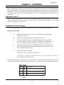
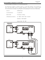
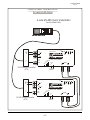
TC1520
RS-422, 2/4-wire RS-485
FIBER OPTIC MODEM
User's Manual
MODEL:
S/N:
DATE:
Notice!
Although every effort has been made to insure that this manual is current
and accurate as of date of publication, no guarantee is given or implied
that this document is error free or accurate with regard to any specification. TC Communications, Inc. reserves the right to change or modify
the contents of this manual at any time without prior notification.
© COPYRIGHT 1992-2004. ALL RIGHTS RESERVED.
TC Communications, Inc. 17575 Cartwright Road - Irvine, CA 92614
Tel: (949) 852-1972
Fax: (949) 852-1948
Web Site: www.tccomm.com
Email: [email protected]
Table Of Contents
TC1520 User's Manual
Rev. 6.7
Chapter 1 - Overview ..................................................................................................3
Description ......................................................................................................................... 3
RS-422 and 4-wire RS-485 Connection .......................................................................... 4
2-wire RS-485 Pin Connection ......................................................................................... 4
Switch Functions ............................................................................................................... 5
Transmission Distances (typical) ..................................................................................... 5
Launch Power & Sensitivity.............................................................................................. 5
Power Supply ..................................................................................................................... 5
LED Functions ................................................................................................................... 6
Theory of 2-Wire RS-485 Operation ................................................................................ 7
Termination of RS-422 or 2-wire RS-485 ........................................................................ 8
Chapter 2 - Installation .................................................................................................9
Unpacking the Unit ............................................................................................................ 9
Equipment Location .......................................................................................................... 9
Installation Procedure Summary ..................................................................................... 9
Quick Installation example for 4-wire RS-485 .............................................................. 10
Quick Installation example for 2-wire RS-485 .............................................................. 11
Testing for the 2-wire RS-485 with RS-530 tester ....................................................... 12
Testing for the 2-wire RS-485 with RS-449 tester ....................................................... 13
Chapter 3 - Specifications ..........................................................................................14
Chapter 4 - Appendix ..................................................................................................15
Return Policy ................................................................................................................... 15
Warranty ........................................................................................................................... 15
−2−
TC1520 User's Manual
Rev. 6.7
Chapter 1 - Overview
Description
The TC1520 Fiber Optic Modems interconnect a host controller with remote RTU (remote terminal unit)
devices fitted with RS-422 and 4-wire or 2-wire RS-485 interfaces. Asynchronous data rates up to 500kbps
are supported. The RS-422 interface is standard, 4-wire or 2-wire RS-485 interface is switch selectable.
The TC1520 is equipped with four DIP switches and six LED indicators on the top of the cover to facilitate
the installation and troubleshooting process.
The TC1520T is a high temperature option (-20o C to 70o C). Fiber optic connectors are ST; FC is optional.
Electrical connectors are terminal blocks.
Terminal blocks for
RS-422/RS-485 signal
input to TC1520
Terminal blocks for
RS-422/RS-485 signal
output to user’s
device
Mounting holes
+
_
+
_
NOT USED
SIG GND
Terminal blocks for
signal ground
LED Indicators for
power supply
optic detection
electrical signal monitoring
Indicator for RS-485 mode
FRM GND
PWR
Made in U.S.A.
IN
RS
485
DRV
MODE
OPTIC
SYNC
RD
TD
OUT
RS-422/485 4/2 WIRE ASYNC
FIBER OPTIC MODEM
OUT-TRM
IN-TRM
CLK2
CLK1
9-14V
DC
+
OPTIC
Tx
Rx
DC power supply
input
Mounting hole
4 DIP switches:
sw1, sw2 for RS-485 transition time (RS-485 only)
sw3, sw4 for termination resistors
UP
DOWN
−3−
Optical Interface
TC1520 User's Manual
Rev. 6.7
RS-422 and 4-wire RS-485 Connection
When both CLK and CLK2 switches are at the “UP” position, the TC1520 is setup for an RS-422 application.
When any or both of CLK and CLK2 is at the “DOWN” position, the TC1520 is setup for an RS-485
application. The CLK1 and CLK2 should be set according to actual data baud rate. (page 5)
The signal ground should connect to user’s device’s signal ground.
RS-422/RS-485
from user’s device
RS-422/RS-485
to user’s device
+
+
+
_
+
_
PWR
Made in U.S.A.
IN
RS
485
RD
OPTIC
SYNC
TD
OUT
RS-422/485 4/ 2 WIRE ASYNC
FIBER OPTIC MODEM
NOT USED
connect to user’s device
DRV
MODE
OUT-TRM
IN-TRM
CLK2
CLK1
SIG GND
FRM GND
9-14V
DC
+
OPTIC
Rx
Tx
2-wire RS-485 Pin Connection
For 2-wire RS-485 application, only “IN” signals should be used. The signal ground should connect to user’s
device’s signal ground.
2-wire RS-485
to user’s device
+
not used for 2-wire RS-485
+
_
+
_
PWR
Made in U.S.A.
IN
RS
485
SIG GND
FRM GND
RD
OUT
RS-422/485 4/2 WIRE ASYNC
FIBER OPTIC MODEM
NOT USED
connect to user’s device
DRV
MODE
OUT-TRM
IN-TRM
CLK2
CLK1
−4−
9-14V
DC
+
OPTIC
Tx
Rx
OPTIC
SYNC
TD
TC1520 User's Manual
Rev. 6.7
Switch Functions
CLK1, CLK2
tw o s w itc h e s m a r k e d a s “ C L K 1 ,” “ C L K 2 ” a r e fo r R S - 4 8 5 ’s tr a n s itio n tim e s e tu p . If b o th s w itc h e s a r e a t
“ u p ” p o s it io n , t h e n “ I N ” a n d “ O U T ” t e r m in a ls a r e s e t u p t o R S - 4 2 2 ’s a p p lic a t io n s . I f b o t h o r a n y o f “ C L K 1 ”
a n d “ C L K 2 ” is s e t t o “ d o w n ” p o s it io n t h e e le c t r ic a l in t e r f a c e is s e t t o R S - 4 8 5 a p p lic a t io n s .
IN-TRM, OUT-TRM - T h e o t h e r t w o s w i t c h e s m a r k e d a s “ I N - T R M ” a n d “ O U T - T R M ” a r e u s e d f o r
t e r m in a t io n r e s is t o r s . “ I N - T R M ” is f o r in p u t t e r m in a t io n a n d “ O U T - T R M ” is f o r o u t p u t t e r m in a t io n .
RS-422 only
4/2-wire RS-485 for baud rate > 9600bps
4/2-wire RS-485 for baud rate > 25 kbps
4/2-wire RS-485 for baud rate > 250 kbps
0 = UP
1 = DOWN
Transmission Distances (typical)
The TC1520 is compatible with all popular sizes and types of fiber. Transmission distances up to 3km* are
typical over Multimode fiber at 850nm and 4km* at 1310nm. Distances to 35km* are typical over Single
Mode fiber at 1310nm.
Launch Power & Sensitivity
Transmitter:
LED/ELED; typical Launch Power -
-20dBm* (850nm/1310nm MM, @62.5/125µm)
-16dBm* (1310nm Single Mode, @9/125µm)
Receiver:
PIN Diode; typical Sensitivity -
-36dBm* (850nm/1310nm MM, @62.5/125µm)
-36dBm* (1310nm Single Mode, @9/125µm)
*Launch power, sensitivity and distance are listed for reference only. These numbers may vary.
Power Supply
Typically, a 9V to 14V DC power supply @200mA is adequate for the TC1520 , optional 115 /230VAC with
an external power cube. The power plug is a terminal block connector with positive & negative polarity
indicated on the top panel of the unit.
−5−
TC1520 User's Manual
Rev. 6.7
LED Functions
T h e r e a r e s ix
R S -4 2 2 /R S “ d r iv e ” o r “ r e
is th e s ta tu s
L E
4 8
c e
o n
D in
5 s ig
iv e ”
“O U
d ic a t o r s t o e a
n a l s ta tu s a t
m o d e a t “O U
T ” te r m in a ls
s e in s t a lla t io n a n d t r o u b le s h o o t in g . U s e r s c a n m o n it o r o p t ic s ig n a l s t a t u s ,
“ I N ” a n d “ O U T ” t e r m in a ls , d is t in g u is h R S - 4 2 2 / R S - 4 8 5 m o d e , o r id e n t if y
T ” t e r m in a ls . T h e “ T D ” L E D is th e s t a t u s o n “ I N ” t e r m in a ls , “ R D ” L E D
.
F o r R S - 4 8 5 a p p lic a t io n s , d r iv e m o d e a n d r e c e iv e m o d e f o r “ O U T ” t e r m in a ls is in d ic a t e d b y “ D R V M O D E ”
L E D .
The RS-485 transceiver status for “OUT” terminals:
When LED is on, “OUT” terminals are in “drive” mode
When LED is off, “OUT” terminals are in “receive” mode.
Actual logic status on “OUT” terminals.
When LED is off, output voltage on “+” is higher than “-”.
When LED is on, output voltage on “+” is lower than “-”.
DC power supply indicator
PWR
RS
485
RS-485 mode indicator:
When LED is “on”, TC1520 is in RS-485 mode.
When LED is “off”, TC1520 is in RS-422 mode.
DRV
MODE
OPTIC
SYNC
RD
TD
Optic sync indicators:
Flashing: Optic signal lost or below optic receiver’s sensitivity.
On: Optic signal is present at pertinent channel (A or B)
Actual logic status on “IN” terminals.
When voltage on “+” is higher than “-”, the LED is off.
When voltage on “+” is lower than “-”, the LED is on.
−6−
TC1520 User's Manual
Rev. 6.7
Theory of 2-Wire RS-485 Operation
Fiber cable
2-wire RS-485 is half-duplex operation, which means transmit and receive operations take turns; they do
not operate concurrently. From the user’s point of view, the channel is in receiving mode when no data is
transmitted from the remote unit. The local RS-485 transceiver will change to transmitting mode (Tx mode)
upon receiving the first bit of data from remote unit. The local RS-485 transceiver will stay in Tx mode until
a predetermined period (set by front panel switch CLK1, CLK2) elapses after the last bit from the remote
unit. The following table provides the setting of the front panel DIP switches which determine the elapsed
period after the last bit of the data stream’s received from remote unit. The listed baud rates is only for
reference. The best result still comes from trial and error. For example, if you know the async data baud
rate is 9600, then set CLK1 to “DOWN”, CLK2 to “UP”. You may also want to try the 25K and 250K
settings for a 9600 baud rate as a test to make sure the best transition time.
Important thing to remember is to try the fastes transition time first (the default setting) which usually would
work for most of the baud rate.
RS-422 only
4/2-wire RS-485 for baud rate > 9600bps
4/2-wire RS-485 for baud rate > 25 kbps
4/2-wire RS-485 for baud rate > 250 kbps
0 = UP
1 = DOWN
−7−
TC1520 User's Manual
Rev. 6.7
Termination of RS-422 or 2-wire RS-485
A termination resistor is necessary for RS-422 or RS-485 applications. Without proper termination, the error
rate of data transmission may be high. The termination resistor is a 120 ohm resistor located only at the
beginning or end of the electrical bus as shown in the following diagram. TC1520 is equipped with two DIP
switches, “IN-TRM” and “OUT-TRM”, for input and output termination resistors. Their functions are
depicted as following:
Termination
RS-422/RS-485
device
RS-422/RS-485
device
RS-422/RS-485
device
RS-422/RS-485
device
120 ohm
120 ohm
OUT-TRM
IN-TRM
UP position- input termination resistor is off
IN-TRM
DOWN position- input termination resistor is ON
UP position- output termination resistor is off
OUT-TRM
DOWN position- output termination resistor is ON
When switch “OUT TRM” is ON (down)
out +
120 ohm
out-
When switch “IN TRM” is ON (down)
in +
120 ohm
in-
−8−
Chapter 2 - Installation
TC1520 User's Manual
Rev. 6.7
Unpacking the Unit
Before unpacking any equipment, inspect all shipping containers for evidence of external damage caused
during transportation. The equipment should also be inspected for damage after it is removed from the
container(s). Claims concerning shipping damage should be made directly to the pertinent shipping agencies.
Any discrepancies should be reported immediately to the TC Communications Inc. Customer Service
Department.
Equipment Location
The TC1520 should be located in an area that provides adequate lighting and working space. Avoid locating
it next to any equipment that may produce electrical interference or strong magnetic fields, such as elevator
shafts, heavy duty power supplies, etc.
Installation Procedure Summary
The TC1520 is designed for quick and easy installation. Follow the diagram on the next page.
Installation Procedure:
A.
Plug in the 12VDC power supply to TC1520, all the LEDs except PWR should
flash for three seconds.
B.
Connect the local and remote units with optic cables as shown.
C.
Connect your local user’s device. (See installation diagram on last page) Make
sure polarity matches. The “TD” LED shows the logic status of input (from user’s
device). The “RD” LED shows the logic status of output (to user’s device).
D.
Connect the optic cable as shown in installation diagram. Observe that the “OPT
SYNC” LED should be flashing when no optic signal is received then turn to solid
after a valid optic signal is received.
F.
Make sure the DIP switch settings:
for RS-422— CLK1 and CLK2 should be “UP”.
for RS-485— CLK1 and CLK2 should be set according to data rate.
(refer to the following table below).
NOTE: After installation is completed, it is an excellent idea to verify and record the optical cable loss. This
reading will both verify the integrity of the circuit and provide a benchmark for future troubleshooting efforts.
RS-422 only
4/2-wire RS-485 for baud rate > 9600bps
4/2-wire RS-485 for baud rate > 25 kbps
4/2-wire RS-485 for baud rate > 250 kbps
0 = UP
1 = DOWN
−9−
TC1520 User's Manual
Rev. 6.7
Quick Installation example for 4-wire RS-485
Following diagram is an example for a 4-wire RS-485 application.
The host controller is communication with a remote device 2 through a 4-wire RS-485 bus. The data sent
is continuous data stream.
date rate:
9600Baud async
electrical interface:
4-wire RS-485
DIP switches:
CLK1 down, CLK2 up.
LED indicators to observe:
on: “PWR” “OPTIC SYNC” “RS-485”
flash(dim): “TD” “RD” “DRV MODE”
User’s device 1
PWR
+
_
IN
+
_
OUT
RS
485
OPTIC
SYNC
DRV
MODE
RD
TD
RS-422/485 4/2 WIRE ASYNC
FIBER OPTIC MODEM
NOT USED
Signal ground
Made in U.S.A.
OUT-TRM
IN-TRM
CLK2
CLK1
SIG GND
FRM GND
9-14V
DC
+
OPTIC
Rx
Tx
12VDC
User’s device 2
PWR
+
_
IN
+
_
OUT
RS
485
NOT USED
Signal ground
Made in U.S.A.
SIG GND
FRM GND
DRV
MODE
OPTIC
SYNC
RD
RS-422/485 4/2 WIRE ASYNC
FIBER OPTIC MODEM
OUT-TRM
IN-TRM
CLK2
CLK1
9-14V
DC
+
12VDC
−10−
OPTIC
Tx
Rx
TD
TC1520 User's Manual
Rev. 6.7
Quick Installation example for 2-wire RS-485
Following diagram is an example for a 2-wire RS-485 application.
The SCADA host computer is polling the status of a remote RTU through a 2-wire RS-485 bus.
Once the remote RTU receives a polling command, it answers with a response signal.
The communication is half-duplex, the polling device and responding device take turns to transmitting.
date rate:
9600Baud async
electrical interface:
2-wire RS-485
DIP switches:
CLK1 down, CLK2 up.
LED indicators to observe:
on: “PWR” “OPTIC SYNC” “RS-485”
flash(dim): “DRV MODE”
alternate flash: “TD” “RD”
SCADA HOST
COMPUTER
PWR
+
_
IN
Made in U.S.A.
RS
485
DRV
MODE
OPTIC
SYNC
RD
TD
OUT
RS-422/485 4/2 WIRE ASYNC
FIBER OPTIC MODEM
NOT USED
Signal ground
OUT-TRM
IN-TRM
CLK2
CLK1
SIG GND
FRM GND
9-14V
DC
+
OPTIC
Rx
Tx
12VDC
RTU
PWR
+
_
IN
Made in U.S.A.
RS
485
DRV
MODE
OPTIC
SYNC
RD
OUT
NOT USED
Signal ground
SIG GND
FRM GND
RS-422/485 4/2 WIRE ASYNC
FIBER OPTIC MODEM
OUT-TRM
IN-TRM
CLK2
CLK1
9-14V
DC
+
12VDC
−11−
OPTIC
Tx
Rx
TD
TC1520 User's Manual
Rev. 6.7
Connect to a BERT Tester with RS-530
for 2-wire RS-485 Testing
2-wire RS-485 Quick Installation
(local & remote Units)
14
2
+
_
+
_
PWR
Made in U.S.A.
IN
RS
485
SIG GND
FRM GND
RS-530 (Db25) Connector
(DTE)
OPTIC
9-14V
DC
+
Tx
Rx
12VDC
+
_
+
_
PWR
Made in U.S.A.
IN
RS
485
SIG GND
FRM GND
DRV
MODE
RD
OUT
RS-422/485 4/2 WIRE ASYNC
FIBER OPTIC MODEM
NOT USED
7
OPTIC
SYNC
TD
RS-422/485 4/2 WIRE ASYNC
FIBER OPTIC MODEM
OUT-TRM
IN-TRM
CLK2
CLK1
16
3
RD
OUT
NOT USED
7
DRV
MODE
OUT-TRM
IN-TRM
CLK2
CLK1
RS-530 (DB25) Connector
(DTE)
9-14V
DC
+
12VDC
−12−
OPTIC
Tx
Rx
OPTIC
SYNC
TD
TC1520 User's Manual
Rev. 6.7
Connect to a BERT Tester with RS-449
for 2-wire RS-485 Testing
2-wire RS-485 Quick Installation
(local & remote Units)
22
4
+
_
+
_
PWR
Made in U.S.A.
IN
RS
485
OUT-TRM
IN-TRM
CLK2
CLK1
SIG GND
FRM GND
OPTIC
9-14V
DC
+
Tx
Rx
12VDC
+
_
+
_
PWR
Made in U.S.A.
IN
RS
485
SIG GND
FRM GND
DRV
MODE
RD
OUT
RS-422/485 4/2 WIRE ASYNC
FIBER OPTIC MODEM
NOT USED
19
OPTIC
SYNC
TD
RS-422/485 4/2 WIRE ASYNC
FIBER OPTIC MODEM
RS-449 (DB37) Connector
(DTE)
24
6
RD
OUT
NOT USED
19
DRV
MODE
OUT-TRM
IN-TRM
CLK2
CLK1
RS-449 (DB37) Connector
(DTE)
9-14V
DC
+
12VDC
−13−
OPTIC
Tx
Rx
OPTIC
SYNC
TD
Chapter 3 - Specifications
TC1520 User's Manual
Rev. 6.7
Data Rates
Async ................................................................................................... up to 500kbps
Optical
Transmitter ................................................................................................. LED/ELED
Receiver ................................................................................................................ PIN
Wavelength ...................................................................... 850nm/1300nm multimode
.................................................................................... 1300nm/1550nm single mode
Fiber Optic connectors .............................................................. *ST (FC optional)
Loss Budget**
.............................................................. 15 dB multimode 850nm/1300nm @62.5µm
............................................................................ 20 dB single mode 1300nm @9µm
Electrical
Connector ........................................................................................ Terminal Blocks
Interface ............................................................................ RS-422 or 4/2-wire RS-485
* ST is a trademark of AT&T
** check factory for laser version
System
9
Bit error rate ................................................................................... 1 in 10 or better
Visual indicator .......................... OPT SYNC, TxD, RxD, DRV MODE, RS-485, PWR
Alarm ........................................................................................ Alarm, OPT-A, OPT-B
Power
Power source .................................................................................... 12VDC@200mA
Optional ............................................................................................. 24VDC@100mA
Optional ................................................... 115 or 230VAC with external power cube
Temperature
o
o
Operating ............................................................................................ -10 C to 50 C
o
o
Hi-Temp(Optional) .............................................................................. -20 C to 70 C
o
o
Storage ................................................................................................ -40 C to 90 C
Humidity .................................................................................. 95% non-condensing
Physical
Height ................................................................................................. (1.91 cm) 0.75"
Width ................................................................................................... (10.16 cm) 4.0"
Depth ..................................................................................................... (6.10 cm) 2.4"
Weight ................................................................................................... (275 gm) 7oz
−14−
Appendix A
TC1520 User's Manual
Rev. 6.7
Return Policy
To return a product, you must first obtain a Return Material Authorization number from the Customer
Service Department. If the product’s warranty has expired, you will need to provide a purchase order to
authorize the repair. When returning a product for a suspected failure, please provide a description of the
problem and any results of diagnostic tests that have been conducted.
Warranty
Damages by lightning or power surges are not covered under this warranty.
All products manufactured by TC Communications, Inc. come with a five year (beginning 1-1-02)
warranty. TC Communications, Inc. warrants to the Buyer that all goods sold will perform in accordance
with the applicable data sheets, drawings or written specifications. It also warrants that, at the time of sale,
the goods will be free from defects in material or workmanship. This warranty shall apply for a period of
five years from the date of shipment, unless goods have been subject to misuse, neglect, altered or destroyed
serial number labels, accidents (damages caused in whole or in part to accident, lightning, power surge,
floods, fires, earthquakes, natural disasters, or Acts of God.), improper installation or maintenance, or
alteration or repair by anyone other than Seller or its authorized representative.
Buyer should notify TC Communications, Inc. promptly in writing of any claim based upon warranty, and
TC Communications, Inc., at its option, may first inspect such goods at the premises of the Buyer, or may
give written authorization to Buyer to return the goods to TC Communications, Inc., transportation charges
prepaid, for examination by TC Communications, Inc. Buyer shall bear the risk of loss until all goods
authorized to be returned are delivered to TC Communications, Inc. TC Communications, Inc. shall not be
liable for any inspection, packing or labor costs in connection with the return of goods.
In the event that TC Communications, Inc. breaches its obligation of warranty, the sole and exclusive
remedy of the Buyer is limited to replacement, repair or credit of the purchase price, at TC Communications,
Inc.’s option.
To return a product, you must first obtain a Return Material Authorization (RMA) number and RMA form
from the Customer Service Department. If the product’s warranty has expired, you will need to provide a
purchase order to authorize the repair. When returning a product for a suspected failure, please fill out RMA
form provided with a description of the problem(s) and any results of diagnostic tests that have been
conducted. The shipping expense to TC Communications should be prepaid. The product should be properly
packaged and insured. After the product is repaired, TC Communications will ship the product back to the
shipper at TC's cost to U.S. domestic destinations. (Foreign customers are responsible for all shipping costs,
duties and taxes [both ways]. We will reject any packages with airway bill indicating TC communications
is responsible for Duties and Taxes. To avoid Customs Duties and Taxes, please include proper documents
indicating the product(s) are returned for repair/retest).
−15−